US5638481A - Flush mounted outlet - Google Patents
Flush mounted outletDownload PDFInfo
- Publication number
- US5638481A US5638481AUS08/534,218US53421895AUS5638481AUS 5638481 AUS5638481 AUS 5638481AUS 53421895 AUS53421895 AUS 53421895AUS 5638481 AUS5638481 AUS 5638481A
- Authority
- US
- United States
- Prior art keywords
- wall plate
- outlet assembly
- outlet
- mounting
- hood
- Prior art date
- Legal status (The legal status is an assumption and is not a legal conclusion. Google has not performed a legal analysis and makes no representation as to the accuracy of the status listed.)
- Expired - Fee Related
Links
Images


Classifications
- G—PHYSICS
- G02—OPTICS
- G02B—OPTICAL ELEMENTS, SYSTEMS OR APPARATUS
- G02B6/00—Light guides; Structural details of arrangements comprising light guides and other optical elements, e.g. couplings
- G02B6/24—Coupling light guides
- G02B6/36—Mechanical coupling means
- G02B6/38—Mechanical coupling means having fibre to fibre mating means
- G02B6/3807—Dismountable connectors, i.e. comprising plugs
- G02B6/3897—Connectors fixed to housings, casing, frames or circuit boards
- G—PHYSICS
- G02—OPTICS
- G02B—OPTICAL ELEMENTS, SYSTEMS OR APPARATUS
- G02B6/00—Light guides; Structural details of arrangements comprising light guides and other optical elements, e.g. couplings
- G02B6/24—Coupling light guides
- G02B6/36—Mechanical coupling means
- G02B6/38—Mechanical coupling means having fibre to fibre mating means
- G02B6/3807—Dismountable connectors, i.e. comprising plugs
- G02B6/381—Dismountable connectors, i.e. comprising plugs of the ferrule type, e.g. fibre ends embedded in ferrules, connecting a pair of fibres
- G02B6/3817—Dismountable connectors, i.e. comprising plugs of the ferrule type, e.g. fibre ends embedded in ferrules, connecting a pair of fibres containing optical and electrical conductors
Definitions
- This inventionrelates to outlets for communication type cables and more particularly to an outlet for connecting multiple types of electrical and optical fiber cables to a standard wall mounted electrical box.
- U.S. Pat. No. 4,261,633there is shown a jack frame molded into a wall plate as an integral part thereof.
- this arrangementhas the disadvantage, as suggested hereinbefore, of requiring a different wall plate for each different jack, different plates being needed for jacks that differ from each other only slightly.
- U.S. Pat. No. 4,859,201represents an improvement over the '633 patent in that it can accommodate a number of jack outlets where, conceivably, the jacks could be different from each other.
- the embodiments disclosed in that patentdo not provide for easy and quick attachment and removal of the jacks to and from the wall plate.
- 5,096,439 of Arnettis directed to an arrangement for mounting a number of jacks to a single wall plate with a simple and convenient arrangement for attaching and releasing the jacks to and from the wall plate.
- the prior artin the electrical communications area, has progressed to the point of accommodating multiple jacks in a single wall plate.
- any arrangement for accommodating both electrical wires and optical fibers in a single flush mounted wall platethere are, in the prior art, arrangements using both electrical and optical connections. However, these arrangements are not flush mounted, generally requiring special boxes for containing the connections, which do not provide ready and easy access to the connectors. In part, this is a consequence of the very special handling and connecting limitations for optical fiber.
- Optical fiber cablesmore particularly single buffered fibers encased in a protective member, require extreme care in handling and in connecting, as well as positioning and storing.
- the fibercannot be wound or bent to a radius less than a prescribed minimum without the occurrence of microcracks.
- connection of the fiber to another fiber or to apparatusrequires that the connector be capable of joining two optical fiber ends with a minimum of insertion loss and it must be mechanically stable while providing adequate protection to the junction between the fibers.
- the connectoris, for the most part, incompatible with each other and which vary as to size, shape and mode of connection. This problem is treated in U.S. Pat. Nos. 5,274,729 of King et al. and 5,238,426 of Arnett in the context of universal patch panels. In the King et al.
- the patch panelhas a plurality of differently sized and shaped openings for accommodating the mounting hardware, by means of build-outs, of a plurality of different optical connectors.
- the Arnett arrangementhas a patch panel or plate having a plurality of substantially identical openings therein in which are mounted adapters for different types of optical couplers as well as electrical couplers. Neither patent deals with wall plates and the additional problems attendant thereto.
- the standard wall platefunctions as a cover for the commonly used NEMA (National Electrical Manufacturers Association) electrical outlet box, generally mounted to the rear of the wall.
- the wall plategenerally has one or more electrical jacks, with connecting wires being stored in the outlet box or passing therethrough, where necessary.
- NEMANational Electrical Manufacturers Association
- Such an assemblyis compact, efficient, and simple to use, the customer, for example, having only to plug a connector jack into its receptacle on the faceplate to complete the connection.
- the prior artfor the most part, does not address making the faceplate universal, i.e., accommodative of both electrical and optical fiber connectors, to the same degree that the universal patch panel has been fabricated. This stems, in part, from the care with which the optical fiber must be treated.
- An SC connectorincludes a ferrule assembly including a barrel having a collar at one end and an optical fiber terminating ferrule projecting from the barrel.
- the ferrule assemblyis disposed in a plug frame such that an end portion of the ferrule projects from one end of the frame.
- the plug frameis configured to snap lock into a grip member, and the grip is inserted into one side of the coupler and locked thereto, while the corresponding grip of another SC connector is inserted into the other side of the coupler and locked.
- the coupleris dimensional such that when the two connectors are inserted therein, the ends of the ferrules abut each other to form a low insertion loss optical connection.
- the plateincorporates a housing member into which the couplers are inserted, thus the body of the coupler extends outwardly from the surface of the wall plate.
- any such mounting of an optical fiberthere are certain restraints that must be observed which are aimed at protecting the fiber.
- the Electronics Industry Association Spec. 568Acalls for at least one meter of fiber slack which may be stored on a storage spool, and a minimum bending radius of three quarters of an inch (3/4").
- any wall mounting for optical fibermust be capable of meeting these constraints, which is difficult to realize where space is at a premium.
- the faceplatehas provision for housing electrical jacks wherein the wires therefrom are passed directly through the container to the outlet box.
- the optical fiber connector modulesare not readily visible and connection thereto is apparently achieved by feel.
- the coveris removable only by unscrewing and thus, ready access to the modules is not easily realized.
- the fiberis coiled somewhat loosely within the container and not well secured therein, and is stored on the room side of the wall, without the protection of the wall against damage
- the present inventionis a flush mounted universal outlet primarily for use in customer premises, wherein both electrical and optical connections are easily made, and which meets the protective restraints specified for optical fibers.
- the term “cable”is used generically to include insulated wires and individual optical fibers, preferably buffered.
- the inventionin an illustrative embodiment thereof, comprises a flush mounted wall plate adapted to, fit to or mate with, a standard outlet box.
- the wall platehas one or more telephone type modular jacks, although other types of connectors, such as coaxial connectors, may be used in place of, or in conjunction with, modular telephone jacks.
- the platehas mounted thereon an optical duplex fiber coupler body for receiving, at the front of the wall plate, first and second optical fiber connectors, preferably, but not necessarily of the SC type.
- the bodyis mounted on the plate, or integral therewith, such that the receptacles therein for receiving the connectors are oriented at an angle to the plane of the wall or faceplate.
- Such angular orientationeliminates, to a large extent, any possible physical interference between the modular telephone jacks and wires and the optical fiber connectors and connected fibers, thereby providing sufficient room for the jacks and the connectors to be independently inserted and removed.
- such angular orientationresults in the connectors, when in place, projecting downward at an angle instead of projecting straight out from the wall or faceplate, which latter is an orientation in which they can be easily damaged by an accidental impingement from, for example, people or moving furniture or apparatus.
- the orientation of the couplers and connectorsmakes them clearly visible to one inserting or removing connectors, thus greatly facilitating such insertion and removal from the room side of the wall.
- the angular orientationalso makes the assembly more compact so that a slidable protective cover or hood, designed to mount to the wall or faceplate, covers both the optical fiber connectors and the electrical connectors.
- the slidable coverprotects the connectors and couplers in use, and can be slid up or removed to provide access to the couplers.
- the faceplatecomprises a first, lower portion which is adapted to be mounted to the front of the outlet box, and a second, upper portion which is pivotally mounted to the first portion.
- the second portionis, like the first portion, adapted to be mounted to the front of the outlet box.
- the front of the faceplateis provided with substantially L-shaped aligned members which define tracks for receiving first and second opposed flanges on the hood or cover so that it may quickly be slid into place over the faceplate to protect the various connectors.
- the covercan be easily removed or slid up from its position covering the fiber connectors for access to the connectors, which, being at an angle, are both visible and accessible to one removing or inserting a connector.
- the guiding and storing meanscomprises a storage spool having guide and retaining members thereon for receiving, holding, and storing the fibers from the rear mounted connectors.
- Projecting from the surface of the spool in the preferred embodimentis a mounting member in the form of a plate having, at the distal end thereof, the male portion or member similar to a telephone connector plug, which is snap fitted into a receptacle in the wall plate by means of one or more resilient tabs.
- the mounting platealso has, intermediate its ends, a curved fiber guide flange for guiding the fibers from the rear mounted connectors to the storage spool, thereby eliminating to a large extent the possibility of fiber kinking, as well as minimizing any unsupported lengths of fibers or slack.
- the storage spoolcan also function as a storage member for electrical wiring from the rear mounted connectors, especially when the wall plate is used with electrical connection and couplers only.
- the storage spool and support plateare dimensioned so that they readily fit within the outlet box when the wall plate is affixed thereto. Also, when the hinged wall plate is swung forward for access to the rear thereof, the spool and mounting plate swing clear of the outlet box without any interference or likelihood of fiber damage.
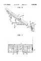
- FIG. 1is a perspective view of the flush mounted wall plate assembly of the present invention
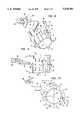
- FIG. 2is a front elevation view of the upper portion of the wall plate of the invention.
- FIG. 3is a rear elevation view of the upper portion of the wall plate of the invention.
- FIG. 4is a perspective front view of the lower portion of the wall plate
- FIG. 5is a perspective rear view of the lower portion of the wall plate
- FIG. 6is a side elevation view of the upper and lower portions of the wall plate as pivotally joined together with the upper portion being partially swung forward;
- FIG. 7is a rear elevation view of the lower portion of the wall plate
- FIG. 8is a top perspective view of the storage spool for use with the wall plate of FIGS. 1, 2 and 3. including its mounting means;
- FIG. 9is a plan view of the top of the storage spool of FIG. 8;
- FIG. 10is a side elevation view of the storage spool of FIG. 8;
- FIG. 11is a top plan view of the hood or cover for use with the wall plate of FIGS. through 5;
- FIG. 12is a side elevation view of the hood of FIG. 11;
- FIG. 13is an end elevation view of the hood of FIG. 11.
- FIG. 14is a bottom plan view of the hood of FIG. 11.
- FIG. 1there is shown the flush mounted wall plate assembly 11 embodying the principles and features of the present invention.
- the wall plate assembly 11is adapted to be mounted on a wall 12 shown in dashed-dot lines in an opening having mounted therein, on the rear side of wall 12, a standard NEMA electrical outlet box 13, shown in dashed lines.
- any connector or outlet mountingshould provide as much protection as possible to the fiber, especially that portion of the fiber that is stored in accordance with the Electronics Industry Association Spec. 568A.
- the mountingshould be capable of providing ready access to the stored fiber, and should be configured to provide and ready and preferably visible connection thereto without the necessity of partially disassembling the mounting.
- the wall plate assembly 11which comprises a flush mounted wall plate 14 having a lower portion 16 and an upper portion 17 which is pivotally mounted to lower portion 16 by means of a pivot pin 18.
- Lower portion 16has a centrally located opening 19 into which a mounting screw (not shown) is inserted and which passes through a corresponding hole in the wall 12 and screws into a threaded mounting hole in outlet box 13.
- lower wall plate 16is affixed to the wall 12 and the outlet box 13.
- upper wall plate portion 17has an upper mounting hole near the upper end thereof for receiving a mounting bolt (not shown) thereby securing upper portion 17 in place.
- portion 17 of wall plate 14can be swung forward and down, pivoting by means of pin 18, to provide access to the rear of upper portion 17.
- a fiber storage spool 21which comprises a cylindrical member 22 having a radius of curvature of its outer surface 23 of at least three-quarters of an inch (3/4"), which is the minimum recommended radius for fiber curvature specified in the aforementioned Electronics Industry Association Spec. 568A.
- the minimum radius for the fiberis no less than threequarters of an inch (3/4"), and the fiber is firmly supported on the surface 23 of spool 21.
- Spool 21has radially extending tabs 24 at the ends thereof and fiber locating fingers 26 for insuring that the fibers wound thereon to not slip off of the spool 21 or become entangled.
- Spool 21 and an integral mounting arm 25are so dimensioned that when upper wall plate portion 17 is swung upward into its operative, vertical position, they enter outlet box 13 without any interference, and, when upper portion 17 is affixed in place, are substantially completely protected within box 13, behind wall 12.
- a protuberant member 28Extending from the front face 27 of upper portion 17 is a protuberant member 28 having a front face 29 oriented at an angle to the plane of front face 27. As shown in FIG. 1, the front face 29 is at an acute angle to the front face 27 and hence, to the plane of the wall plate 14. Face 29 has first and second apertures 31, only one of which is clearly shown in FIG. 1, which are adapted to receive and hold first and second duplex couplers 32, as shown. As will be apparent hereinafter, openings or apertures 31 are so configured and dimensioned that, in place of one or more of the duplex couplers 32, the female portion of the modular telephone jack may be substituted.
- Each duplex coupler 32is adapted to receive two SC type connectors 33, only one of which is shown. It is to be understood that other types of couplers and connectors may be used, although the use of SC type connectors and couplers is preferred. Extending from the rear of the duplex coupler 32 are first and second SC connectors 34 and 36, with the fiber 37 from connector 34 extending over a fiber guide member 38, mounted on or integral with mounting arm 25, and the fiber 39 from 36 extending directly onto the surface 23 of storage spool 21. Such an arrangement minimizes any slack or unsupported lengths of the fibers 37 and 39, which keeping them separated, thereby avoiding tangling or interference with each other.
- Face 29also has a third aperture 41 into which is fitted the female portion 42 of a modular telephone jack, as shown, and a fourth aperture 43 for receiving the female portion 44. Face 29 also has a fifth aperture 46, as will be best seen in FIG. 2, for receiving a mounting lock (not shown), positioned on the distal end of arm 25 of the storage spool 21 for locking spool 21 in place at the rear of faceplate 14.
- the apertures 31, 31, 41 and 43may be configured in different ways to accommodate various types of connectors, however, the configurations shown in FIG. 1 are the preferred ones. All of the apertures, and the couplers mounted therein, are visible from the front of faceplate 14 when it is mounted in place, thereby materially facilitating the insertion and removal of the connectors from the front.
- cover 47has first and second inwardly extending mounting flanges 48 and 49 for slidably mounting cover 47 to the front 27 of faceplate 14.
- the upper portion 17 of faceplate 14has track defining L-shaped brackets 51 and 52 and the lower portion has L-shaped brackets 53 and 54 which define the lower portion of the tracks for flanges 48 and 49.
- the flanges 48 and 49are inserted in their respective tracks and cover 47 is slid down along the tracks until the front face 27 and, more particularly, the connectors and couplers, are substantially completely covered.
- cover 47can simply be slid up partially or completely to provide such access.
- FIGS. 2 and 3there are shown front and rear views, respectively, of the upper portion 17 of wall or faceplate 14, and in FIGS. 4 and 5, front and rear perspective views, respectively of the lower portion 16 of wall or faceplate 14.
- Faceplate 14is preferably made of a suitable plastic material such as, for example, a polycarbonate-ABS blend, which is both hard and durable, and which can readily be injection molded.
- the upper portion 17 of plate 14, as shown in FIGS. 2 and 3comprises a substantially rectangular member having at the lower end thereof, a mounting tang 56 having, at the distal end thereof a pivot pin 18.
- one end of pin 18has an enlarged portion 57 which is tapered to a point 58 and the other end of pin 18 also is tapered to a point 59.
- Tang 56has aperture 19 therein through which a mounting screw passes.
- L-shaped brackets 51, 51 and 52, 52Extending substantially parallel to the sides of plate portion 17 are the L-shaped brackets 51, 51 and 52, 52, which, as pointed out hereinbefore, define tracks for the flanges 48 and 49 of hood 47 so that the hood 47 may be slid down over the front face 27 of portion 17 and, when in its "down" position, held in place.
- a mounting boss 61having an aperture 62 therein, is located along the longitudinal center line of portion 17, with the center of aperture 62 being spaced from the center of aperture 19, a distance equal to the tapped mounting holes in the standard NEMA outlet box.
- a stop lug 63Extending upward from box 61 is a stop lug 63 which, as will be more apparent hereinafter, functions as a stop for hood 47.
- Protuberant member 28has, in the front face 29 thereof, which is stepped, as best seen in FIG. 1, to produce an upper flat portion 64 and a lower flat portion 66, first and second apertures 31, 31 in the lower portion 66, each of which is dimensional to receive a duplex coupler 32, as best seen in FIG. 1.
- the upper flat portion 64has third and fourth aperture 41 and 43 for receiving the female member 42 and 44 of a pair of telephone jacks of standard configuration.
- the openings 31,31are also dimensional to receive, where necessary, the female members of telephone jacks instead of the duplex couplers.
- a fifth aperture 46which has a configuration similar to the female opening in a telephone jack for receiving a mounting lock on the storage spool 21 to lock the spool 21 to the rear of faceplate 14, as will be explained more fully hereinafter.
- FIGS. 4, 5 and 7, the lower portion 16 of faceplate 14is shown, to which, in use, the upper portion 17 is pivotally mounted.
- Portion 16has first and second side sections 67 and 68 joined by a web member 69.
- Member 69has a centrally located aperture 71 having an apertured floor portion 72 which has a smaller aperture 73.
- Aperture 73is sufficiently large to allow passage of the shank of a mounting bolt, but not the head thereof As a consequence, when member 16 is mounted in place and to outlet box 13, the head of the bolt bears against the floor 72 of aperture 71.
- member or portion 16has L-shaped brackets 53 and 54, which, together with brackets 51 and 52 on member or portion 17, define the tracks for the flanges 48 and 49 of the hood 47.
- Web 69which is not as long as either side 67 or 68, forms therewith a centrally located opening 74 which is further defined by spaced ribs 76 and 77.
- the spacing of ribs 76 and 77is slightly greater than the width of tang 56 so that, when the faceplate is fully assembled as seen in FIG. 1, tang 56 is restrained from lateral movement by the ribs.
- the ribsdefine the narrowest portion of opening 74, which has angled side members 78 and 79 extending from the front of the back of member 16 or, as viewed in FIG. 4, from top to bottom.
- pin receiving slots 82 and 83On the sides of opening 74 are pin receiving slots 82 and 83, the inner ends of which have the ribs 76 and 77 respectively, extending across the top, as seen in FIGS. 4 and 5.
- the bottom walls 80 and 81 of slots 82 and 83are radiused at 84 and 86 as shown, and the undersides of ribs 76 and 77 are sloped and radiused as best seen in FIG. 5.
- member 17is swung down below members 16 to an orientation shown in dashed lines in FIG. 7 where the angle of orientation relative to member 16 is preferably greater than 180°, and by dashed lines in FIG. 4. Because of the sloping surfaces 78 and 79, tang 56 can be moved laterally inasmuch as it is at the widest portion of the opening 74. Thus, tang 56 can be shifted to the left, as viewed in FIG. 4 until the tip 59 of pin 18 clears the radiused portion 84 and the small end of pin 18 enters slot 83, passing under rib 77. Tang 56 is then shifted to the right as viewed in FIG.
- hood 47When hood 47 is slid into place with the L-shaped brackets 51, 52, 53 and 54 holding flanges 48 and 49 in place, lower and upper portions 16 and 17 are locked in place, hence, even if the bolt for fastening the upper portion 17 to the box 13 should work loose or were missing, the plate 14 would still be flat against the wall.
- hood 47is removed and pivoted in the direction of arrow B, as discussed hereinbefore.
- upper portion 17would have to be pivoted down past the vertical to at least the position shown by the dashed lines before there would be any possibility of the pivot pin 18 slipping out of its slots 82 and 83. Inasmuch as the assembled wall plate 14 is flat against the wall, it would be impossible for it to be swung past the vertical, hence there is no danger of an accidental detachment of upper portion 17 from lower portion 16.
- Storage spool or drum 21is shown in perspective in FIG. 8 and in plan and elevation views in FIGS. 9 and 10, respectively.
- Spool 21which is made of suitable material such as, for example, a polycarbonate-ABS blend, comprises a cylindrical member 22 having a longitudinal axis, an outer surface 23 which has a radius of curvature of three-quarters of an inch (3/4") or more, thus insuring that optical fibers, preferably buffered, wrapped and stored thereon will have a minimum bend radius of three-quarters of an inch (3/4") which, as pointed out hereinbefore, is the minimum recommended radius for fiber curvature specified in Electronics Industry Association Spec. 568A.
- each end of the cylinder 22are angularly spaced radially projecting retaining tabs 24, with the tabs on end being angularly offset from the tabs on the other end, as best seen in FIG. 10.
- one of the tabs 24 closest to the wall plate when the spool is mounted thereonhas an angled or beveled portion 84 which facilitates winding optical fibers onto the spool.
- the tabs 24perform the primary function of preventing fibers wound on the spool from slipping off at the ends thereof.
- a mounting arm 25integral with cylinder 22.
- Ann 25has a first divider septum or wall 86 at its proximal end, which, in effect, divides cylinder 22 into two storage areas.
- Extending from wall 86is an elongated arm 87 which has at the distal end thereof a spring latch mounting and locking member 88 which is adapted to fit within the aperture 46 and locked therein by means of cantilever spring 89 in the same manner that the male member of telephone jack locks into the female member.
- arm 87is offset from wall 86 in order that member 88 is aligned with the opening 46 in plate 17 while maintaining the spool in a central position.
- an arcuate fiber guide member 38is mounted on or integral with the dividing wall member 86, and extending outward therefrom on either side.
- guide member 38is used to maintain separation between the fiber from connector 34 and the fiber from connector 36 while providing support from the fibers, thereby minimizing slack fiber.
- the fiber from connector 34is passed over guide member 38 and supported thereby, and the fiber from connector 36, the end of which is close to surface 23, is passed under guide 38, and the fibers are then wound on spool 22 for storage and to provide the required maximum of one meter of excess fiber, as discussed hereinbefore.
- first and second separating walls 92 and 93Centrally located on spool 22 and extending radially therefrom are first and second separating walls 92 and 93 from which extend fiber locating and retaining fingers 26,26 which are substantially parallel to the axis of cylinder 22 and spaced from surface 23.
- the walls 92 and 93assist in maintaining separation of the fibers and the fingers 26 function to hold the fibers on or close to surface 23, thereby minimizing or preventing any loops of slack fiber.
- the dimensions of the spool 21 and its mounting arm 25are such that, when the spool is mounted to the rear of upper portion 17 of hinged faceplate 14, there is no interference between spool 21 and the walls of the outlet box 13, either when the spool is enclosed therein or when faceplate portions 17 is pivoted outwardly.
- the enclosing of the spool with the fibers wound thereonadds another order of protection for the fibers. Not only are the fibers protected by being behind the wall and hence isolated from high traffic on the room side of the wall, but the fibers are also protected by the standard outlet box 13.
- Substantially optimum dimensions for the spool assemblyare a radius of curvature of surface 23 of no less than three-quarters of an inch (0.75"), the length of cylinder 22 is approximately one and six-tenths inches (1.6"), walls 92 and 93 are approximately one-quarter of an inch (0.25") high and twelve one-hundredths of an inch (0.12”) thick, and the distal end of arm 25 is approximately two and fifty-nine one-hundredths inches (2.59") from the central axis of cylinder 22.
- hood 47 of FIG. 1is shown in detail in FIGS. 11 through 14. As discussed in the foregoing, hood 47 is removably mounted on the front wall plate 14 when the plate is in its assembled and mounted condition, and can either be partially slid up to provide an open position for access to the various couplers 32, 32, 42 and 44 or can be completely removed when it is desired to pivot upper portion 17 of the wall plate 14 relative to lower portion 16.
- Hood 47which is an elongated substantially hollow member, and which may be made of any suitable light weight semi-rigid material, such as, for example, a polycarbonate-ABS blend, has a U-shaped open lower end 96, as best seen in FIG. 13. The ends of the U-shape terminate in inwardly extending flanges 48 and 49 each of which has a slight taper 97 at the open end, as best seen in FIG. 12, for ease of insertion of the flanges 48 and 49 under the lips of the L-shaped track forming brackets 51, 52, 53 and 54 as seen in FIG. 1.
- Hood 47has an upper end 98 (fight hand end as shown in FIGS.
- End 98is joined to the front end or lower portion 96 of hood 47 by a sloped planar surface 101 which extends, as shown, from a point above lower end 96 to the end 98.
- a stop member 102is currently located, preferably centrally, on the interior side of flat end 98, and, in use, functions to limit the downward movement of hood 47 over face or wall plate 14 by butting against stop member 63 which is best seen in FIG. 2, thereby establishing the closed position of the hood.
- hood 47may be easily moved in the tracks formed by the brackets 51, 52, 53 and 54, the facing tips of the flanges 48 and 49 at the open end 96 are spaced apart a distance B which is slightly greater than the distance A between the tips of the flanges at the closed end 98.
- Protective hood 47may be made opaque, transparent, or translucent, and may be, if desired, colored to match a room decor for example, as may face or wall plate 14.
- the protective hood 47is the subject of U.S. patent application Ser. No. 08/533,156 filed concurrently herewith.
- the flush mounted universal outlet assembly of the invention and the several components thereofprovide a large measure of protection of the various connectors and associated wires or fibers, both by means of the protective hood and the unique configuration which places the stored portions of the optical fibers behind the room wall and within the outlet box.
- the assemblyprovides ready, visible access to all connectors on both the front and the rear of the wall plate, and is designed to mount to a standard outlet box. No special tools are required for assembling the several parts, all of which are readily separable from each other and yet which form a unitary whole.
Landscapes
- Physics & Mathematics (AREA)
- General Physics & Mathematics (AREA)
- Optics & Photonics (AREA)
- Connector Housings Or Holding Contact Members (AREA)
Abstract
Description
Claims (16)
Priority Applications (1)
| Application Number | Priority Date | Filing Date | Title |
|---|---|---|---|
| US08/534,218US5638481A (en) | 1995-09-26 | 1995-09-26 | Flush mounted outlet |
Applications Claiming Priority (1)
| Application Number | Priority Date | Filing Date | Title |
|---|---|---|---|
| US08/534,218US5638481A (en) | 1995-09-26 | 1995-09-26 | Flush mounted outlet |
Publications (1)
| Publication Number | Publication Date |
|---|---|
| US5638481Atrue US5638481A (en) | 1997-06-10 |
Family
ID=24129169
Family Applications (1)
| Application Number | Title | Priority Date | Filing Date |
|---|---|---|---|
| US08/534,218Expired - Fee RelatedUS5638481A (en) | 1995-09-26 | 1995-09-26 | Flush mounted outlet |
Country Status (1)
| Country | Link |
|---|---|
| US (1) | US5638481A (en) |
Cited By (37)
| Publication number | Priority date | Publication date | Assignee | Title |
|---|---|---|---|---|
| US5761368A (en)* | 1995-02-28 | 1998-06-02 | Lucent Technologies Inc. | Storage spool device for optical fibers |
| FR2757644A1 (en)* | 1996-12-24 | 1998-06-26 | Proptic | Distribution box for providing end connections on distribution optical fibre cable |
| US5949946A (en)* | 1997-11-21 | 1999-09-07 | Nortel Networks Corporation | Faceplate with optical adapter carrier |
| US6243526B1 (en)* | 1999-10-26 | 2001-06-05 | Avaya Technology Corp. | Storage spool assembly for optical fiber |
| USD443252S1 (en) | 2000-06-02 | 2001-06-05 | Corning Cable Systems Llc | Wall mount housing |
| US6352374B1 (en)* | 2000-06-08 | 2002-03-05 | Amphenol Corporation | Fiber optic connector device |
| US6359219B1 (en) | 2000-10-10 | 2002-03-19 | William E. Reid | Decorative electrical box |
| US6616005B1 (en)* | 2000-08-28 | 2003-09-09 | Hubbell Incorporated | Modular faceplate assembly for an electrical box |
| US6757470B2 (en) | 2001-12-12 | 2004-06-29 | Alcatel Canada Inc. | Faceplate combination |
| US20050163448A1 (en)* | 2004-01-27 | 2005-07-28 | Blackwell Chois A.Jr. | Multi-port optical connection terminal |
| US20060068633A1 (en)* | 2004-09-24 | 2006-03-30 | Adam Murano | Work station outlet for behind-the-wall cable management |
| US20080131132A1 (en)* | 2006-12-01 | 2008-06-05 | Solheid James J | Network interface device |
| WO2008137894A1 (en)* | 2007-05-07 | 2008-11-13 | Adc Telecommunications, Inc. | Fiber optic enclosure with external cable spool |
| US20080315030A1 (en)* | 2007-06-22 | 2008-12-25 | Furukawa Electric North America, Inc. | Fiber optic rapid spooling tool |
| US20090060441A1 (en)* | 2007-09-05 | 2009-03-05 | Kowalczyk Scott C | Fiber optic enclosure with tear-away spool |
| US20090074370A1 (en)* | 2007-08-06 | 2009-03-19 | Adc Telecommunications, Inc. | Fiber optic enclosure with internal cable spool |
| WO2009155487A1 (en)* | 2008-06-19 | 2009-12-23 | Adc Telecommunications, Inc. | Methods and systems for distributing fiber optic telecommunications services to local area |
| US20100074587A1 (en)* | 2008-09-16 | 2010-03-25 | Todd Loeffelholz | Modular fiber optic enclosure with external cable spool |
| US7740409B2 (en) | 2007-09-19 | 2010-06-22 | Corning Cable Systems Llc | Multi-port optical connection terminal |
| US20110044599A1 (en)* | 2009-07-21 | 2011-02-24 | Adc Telecommunications, Inc. | Rapid universal rack mount enclosure |
| ITMI20112135A1 (en)* | 2011-11-24 | 2013-05-25 | Francesco Bruno | BUILT-IN WALL-MOUNTED ELECTRIC BOX FOR CONTAINMENT OF CONCEALED CLAMPS IN AN INCLINED POSITION |
| US8538010B2 (en) | 2010-04-26 | 2013-09-17 | Tyco Electronics Corporation | Faceplate assembly for wall mounting a phone |
| US8755663B2 (en) | 2010-10-28 | 2014-06-17 | Corning Cable Systems Llc | Impact resistant fiber optic enclosures and related methods |
| US8837940B2 (en) | 2010-04-14 | 2014-09-16 | Adc Telecommunications, Inc. | Methods and systems for distributing fiber optic telecommunication services to local areas and for supporting distributed antenna systems |
| USRE45153E1 (en) | 2007-01-13 | 2014-09-23 | Adc Telecommunications, Inc. | Fiber optic cable distribution box |
| US8873926B2 (en) | 2012-04-26 | 2014-10-28 | Corning Cable Systems Llc | Fiber optic enclosures employing clamping assemblies for strain relief of cables, and related assemblies and methods |
| US9042700B2 (en) | 2010-08-02 | 2015-05-26 | Adc Telecommunications, Inc. | Cable spool assembly |
| US9069151B2 (en) | 2011-10-26 | 2015-06-30 | Corning Cable Systems Llc | Composite cable breakout assembly |
| US9188760B2 (en) | 2011-12-22 | 2015-11-17 | Adc Telecommunications, Inc. | Mini rapid delivery spool |
| US20150370028A1 (en)* | 2010-06-02 | 2015-12-24 | Tyco Electronics Corporation | Switch rack system |
| US9261663B2 (en) | 2010-06-18 | 2016-02-16 | Adc Communications (Shanghai) Co., Ltd. | Fiber optic distribution terminal and method of deploying fiber distribution cable |
| WO2016078712A1 (en) | 2014-11-20 | 2016-05-26 | Prysmian S.P.A. | Optical termination module, optical termination assembly with said optical termination module and electric cabinet with said optical termination module |
| US9885845B2 (en)* | 2015-01-15 | 2018-02-06 | Commscope, Inc. Of North Carolina | Module and assembly for fiber optic interconnections |
| US9995898B2 (en) | 2010-06-23 | 2018-06-12 | Commscope Technologies Llc | Telecommunications assembly |
| US10162143B1 (en)* | 2017-09-21 | 2018-12-25 | Ofs Fitel, Llc | Behind-the-wall fiber spool module |
| US10371914B2 (en) | 2011-06-24 | 2019-08-06 | Commscope Technologies Llc | Fiber termination enclosure with modular plate assemblies |
| US10545305B2 (en) | 2012-12-19 | 2020-01-28 | CommScope Connectivity Belgium BVBA | Distribution device with incrementally added splitters |
Citations (25)
| Publication number | Priority date | Publication date | Assignee | Title |
|---|---|---|---|---|
| US4261633A (en)* | 1979-08-27 | 1981-04-14 | Amp Incorporated | Wiring module for telephone jack |
| JPS60134205A (en)* | 1983-12-23 | 1985-07-17 | Fujitsu Ltd | How to protect optical fiber |
| US4708430A (en)* | 1984-10-25 | 1987-11-24 | Northern Telecom Limited | Cabinet for optical cable terminating equipment |
| US4859201A (en)* | 1986-12-22 | 1989-08-22 | Amp Incorporated | Data communications outlet |
| US4898448A (en)* | 1988-05-02 | 1990-02-06 | Gte Products Corporation | Fiber distribution panel |
| US5024929A (en)* | 1990-04-30 | 1991-06-18 | Eastman Kodak Company | Method of preparing coupler dispersions for photographic use |
| US5041081A (en)* | 1990-05-18 | 1991-08-20 | Odrich Ronald B | Ocular implant for controlling glaucoma |
| US5052775A (en)* | 1989-08-15 | 1991-10-01 | Minnesota Mining And Manufacturing Company | Optical fiber module termination array and panel |
| US5093885A (en)* | 1990-07-11 | 1992-03-03 | Adc Telecommunications, Inc. | Fiber optic connector module |
| US5096439A (en)* | 1991-08-28 | 1992-03-17 | At&T Bell Laboratories | Wall plate having jack-release slots |
| US5109467A (en)* | 1991-02-27 | 1992-04-28 | Keptel, Inc. | Interconnect cabinet for optical fibers |
| US5127082A (en)* | 1991-03-22 | 1992-06-30 | The Siemon Company | Fiber optic patch panel |
| US5129030A (en)* | 1991-05-30 | 1992-07-07 | At&T Bell Laboratories | Movable lightguide connector panel |
| US5133038A (en)* | 1980-04-17 | 1992-07-21 | Reliance Comm/Tec. Corporation | Fiber optic splice case |
| US5138688A (en)* | 1990-11-09 | 1992-08-11 | Northern Telecom Limited | Optical connector holder assembly |
| US5212752A (en)* | 1992-05-27 | 1993-05-18 | At&T Bell Laboratories | Optical fiber ferrule connector having enhanced provisions for tuning |
| US5238426A (en)* | 1992-06-11 | 1993-08-24 | At&T Bell Laboratories | Universal patch panel for communications use in buildings |
| US5274729A (en)* | 1992-07-30 | 1993-12-28 | At&T Bell Laboratories | Universal optical fiber buildout system |
| US5289558A (en)* | 1991-10-05 | 1994-02-22 | Krone Aktiengesellshaft | Switching assembly for glass fiber cables of the telecommunication and data technology |
| US5302140A (en)* | 1993-04-02 | 1994-04-12 | At&T Bell Laboratories | Connector with mounting collar for use in universal patch panel systems |
| US5367598A (en)* | 1993-10-21 | 1994-11-22 | Nec America, Inc. | Interface chassis for fiber optic transport system |
| US5412751A (en)* | 1993-08-31 | 1995-05-02 | The Siemon Company | Retrofittable multimedia patch management system |
| US5442725A (en)* | 1993-08-30 | 1995-08-15 | At&T Corp. | Pivotally mounted tray for organizing optical fibers |
| US5446822A (en)* | 1993-05-28 | 1995-08-29 | Minnesota Mining And Manufacturing Company | Connector clip for fiber optic housing |
| US5490229A (en)* | 1993-12-08 | 1996-02-06 | At&T Ipm Corp. | Slidably mounted optical fiber distribution tray |
- 1995
- 1995-09-26USUS08/534,218patent/US5638481A/ennot_activeExpired - Fee Related
Patent Citations (25)
| Publication number | Priority date | Publication date | Assignee | Title |
|---|---|---|---|---|
| US4261633A (en)* | 1979-08-27 | 1981-04-14 | Amp Incorporated | Wiring module for telephone jack |
| US5133038A (en)* | 1980-04-17 | 1992-07-21 | Reliance Comm/Tec. Corporation | Fiber optic splice case |
| JPS60134205A (en)* | 1983-12-23 | 1985-07-17 | Fujitsu Ltd | How to protect optical fiber |
| US4708430A (en)* | 1984-10-25 | 1987-11-24 | Northern Telecom Limited | Cabinet for optical cable terminating equipment |
| US4859201A (en)* | 1986-12-22 | 1989-08-22 | Amp Incorporated | Data communications outlet |
| US4898448A (en)* | 1988-05-02 | 1990-02-06 | Gte Products Corporation | Fiber distribution panel |
| US5052775A (en)* | 1989-08-15 | 1991-10-01 | Minnesota Mining And Manufacturing Company | Optical fiber module termination array and panel |
| US5024929A (en)* | 1990-04-30 | 1991-06-18 | Eastman Kodak Company | Method of preparing coupler dispersions for photographic use |
| US5041081A (en)* | 1990-05-18 | 1991-08-20 | Odrich Ronald B | Ocular implant for controlling glaucoma |
| US5093885A (en)* | 1990-07-11 | 1992-03-03 | Adc Telecommunications, Inc. | Fiber optic connector module |
| US5138688A (en)* | 1990-11-09 | 1992-08-11 | Northern Telecom Limited | Optical connector holder assembly |
| US5109467A (en)* | 1991-02-27 | 1992-04-28 | Keptel, Inc. | Interconnect cabinet for optical fibers |
| US5127082A (en)* | 1991-03-22 | 1992-06-30 | The Siemon Company | Fiber optic patch panel |
| US5129030A (en)* | 1991-05-30 | 1992-07-07 | At&T Bell Laboratories | Movable lightguide connector panel |
| US5096439A (en)* | 1991-08-28 | 1992-03-17 | At&T Bell Laboratories | Wall plate having jack-release slots |
| US5289558A (en)* | 1991-10-05 | 1994-02-22 | Krone Aktiengesellshaft | Switching assembly for glass fiber cables of the telecommunication and data technology |
| US5212752A (en)* | 1992-05-27 | 1993-05-18 | At&T Bell Laboratories | Optical fiber ferrule connector having enhanced provisions for tuning |
| US5238426A (en)* | 1992-06-11 | 1993-08-24 | At&T Bell Laboratories | Universal patch panel for communications use in buildings |
| US5274729A (en)* | 1992-07-30 | 1993-12-28 | At&T Bell Laboratories | Universal optical fiber buildout system |
| US5302140A (en)* | 1993-04-02 | 1994-04-12 | At&T Bell Laboratories | Connector with mounting collar for use in universal patch panel systems |
| US5446822A (en)* | 1993-05-28 | 1995-08-29 | Minnesota Mining And Manufacturing Company | Connector clip for fiber optic housing |
| US5442725A (en)* | 1993-08-30 | 1995-08-15 | At&T Corp. | Pivotally mounted tray for organizing optical fibers |
| US5412751A (en)* | 1993-08-31 | 1995-05-02 | The Siemon Company | Retrofittable multimedia patch management system |
| US5367598A (en)* | 1993-10-21 | 1994-11-22 | Nec America, Inc. | Interface chassis for fiber optic transport system |
| US5490229A (en)* | 1993-12-08 | 1996-02-06 | At&T Ipm Corp. | Slidably mounted optical fiber distribution tray |
Cited By (131)
| Publication number | Priority date | Publication date | Assignee | Title |
|---|---|---|---|---|
| US5761368A (en)* | 1995-02-28 | 1998-06-02 | Lucent Technologies Inc. | Storage spool device for optical fibers |
| FR2757644A1 (en)* | 1996-12-24 | 1998-06-26 | Proptic | Distribution box for providing end connections on distribution optical fibre cable |
| US5949946A (en)* | 1997-11-21 | 1999-09-07 | Nortel Networks Corporation | Faceplate with optical adapter carrier |
| US6243526B1 (en)* | 1999-10-26 | 2001-06-05 | Avaya Technology Corp. | Storage spool assembly for optical fiber |
| USD443252S1 (en) | 2000-06-02 | 2001-06-05 | Corning Cable Systems Llc | Wall mount housing |
| US6352374B1 (en)* | 2000-06-08 | 2002-03-05 | Amphenol Corporation | Fiber optic connector device |
| US6616005B1 (en)* | 2000-08-28 | 2003-09-09 | Hubbell Incorporated | Modular faceplate assembly for an electrical box |
| US6359219B1 (en) | 2000-10-10 | 2002-03-19 | William E. Reid | Decorative electrical box |
| US6757470B2 (en) | 2001-12-12 | 2004-06-29 | Alcatel Canada Inc. | Faceplate combination |
| US20050163448A1 (en)* | 2004-01-27 | 2005-07-28 | Blackwell Chois A.Jr. | Multi-port optical connection terminal |
| US7653282B2 (en) | 2004-01-27 | 2010-01-26 | Corning Cable Systems Llc | Multi-port optical connection terminal |
| US7333708B2 (en) | 2004-01-27 | 2008-02-19 | Corning Cable Systems Llc | Multi-port optical connection terminal |
| US7120347B2 (en)* | 2004-01-27 | 2006-10-10 | Corning Cable Systems Llc | Multi-port optical connection terminal |
| US20060280420A1 (en)* | 2004-01-27 | 2006-12-14 | Blackwell Chois A Jr | Multi-port optical connection terminal |
| US20060068633A1 (en)* | 2004-09-24 | 2006-03-30 | Adam Murano | Work station outlet for behind-the-wall cable management |
| US7059895B2 (en)* | 2004-09-24 | 2006-06-13 | Ortronics, Inc. | Work station outlet for behind-the-wall cable management |
| US20080131132A1 (en)* | 2006-12-01 | 2008-06-05 | Solheid James J | Network interface device |
| WO2008070445A3 (en)* | 2006-12-01 | 2008-10-02 | Adc Telecommunications Inc | Network interface device |
| US8135256B2 (en) | 2006-12-01 | 2012-03-13 | Adc Telecommunications, Inc. | Network interface device |
| USRE46255E1 (en) | 2007-01-13 | 2016-12-27 | Commscope Technologies Llc | Fiber optic cable distribution box |
| USRE45153E1 (en) | 2007-01-13 | 2014-09-23 | Adc Telecommunications, Inc. | Fiber optic cable distribution box |
| USRE48063E1 (en) | 2007-01-13 | 2020-06-23 | Commscope Technologies Llc | Fiber optic cable distribution box |
| USRE49385E1 (en) | 2007-01-13 | 2023-01-24 | Commscope Technologies Llc | Fiber optic cable distribution box |
| US10627592B2 (en)* | 2007-05-07 | 2020-04-21 | Commscope Technologies Llc | Fiber optic assembly with cable spool |
| US20100247051A1 (en)* | 2007-05-07 | 2010-09-30 | Adc Telecommuncations, Inc. | Fiber optic enclosure with external cable spool |
| WO2008137894A1 (en)* | 2007-05-07 | 2008-11-13 | Adc Telecommunications, Inc. | Fiber optic enclosure with external cable spool |
| US7715679B2 (en)* | 2007-05-07 | 2010-05-11 | Adc Telecommunications, Inc. | Fiber optic enclosure with external cable spool |
| US12235506B2 (en) | 2007-05-07 | 2025-02-25 | Commscope Technologies Llc | Fiber optic enclosure with external cable spool |
| US8380035B2 (en) | 2007-05-07 | 2013-02-19 | Adc Telecommunications, Inc. | Fiber optic enclosure with external cable spool |
| US9057860B2 (en) | 2007-05-07 | 2015-06-16 | Adc Telecommunications, Inc. | Fiber optic enclosure with external cable spool |
| US10788642B2 (en)* | 2007-05-07 | 2020-09-29 | Commscope Technologies Llc | Fiber optic assembly with cable storage arrangement |
| US9535227B2 (en) | 2007-05-07 | 2017-01-03 | Commscope Technologies Llc | Fiber optic cable spool assembly |
| US11009671B2 (en)* | 2007-05-07 | 2021-05-18 | Commscope Technologies Llc | Fiber optic assembly with cable storage arrangement |
| US20080292261A1 (en)* | 2007-05-07 | 2008-11-27 | Kowalczyk Scott C | Fiber optic enclosure with external cable spool |
| US20170235079A1 (en)* | 2007-05-07 | 2017-08-17 | Commscope Technologies Llc | Fiber optic enclosure with external cable spool |
| US20190086629A1 (en)* | 2007-05-07 | 2019-03-21 | Commscope Technologies Llc | Fiber optic assembly with cable storage arrangement |
| US8131126B2 (en) | 2007-05-07 | 2012-03-06 | Adc Telecommunications, Inc. | Fiber optic enclosure with external cable spool |
| US20080315030A1 (en)* | 2007-06-22 | 2008-12-25 | Furukawa Electric North America, Inc. | Fiber optic rapid spooling tool |
| US7748660B2 (en)* | 2007-06-22 | 2010-07-06 | Ofs Fitel, Llc | Fiber optic rapid spooling tool |
| US10712518B2 (en) | 2007-08-06 | 2020-07-14 | Commscope Technologies Llc | Fiber optic enclosure with lockable internal cable spool |
| US10495836B2 (en) | 2007-08-06 | 2019-12-03 | Commscope Technologies Llc | Fiber optic payout assembly including cable spool |
| US8189984B2 (en) | 2007-08-06 | 2012-05-29 | Adc Telecommunications, Inc. | Fiber optic enclosure with internal cable spool |
| US12019301B2 (en) | 2007-08-06 | 2024-06-25 | Commscope Technologies Llc | Fiber optic enclosure with internal cable spool |
| US20090074370A1 (en)* | 2007-08-06 | 2009-03-19 | Adc Telecommunications, Inc. | Fiber optic enclosure with internal cable spool |
| US12253734B2 (en) | 2007-08-06 | 2025-03-18 | Commscope Technologies Llc | Fiber optic enclosure with internal cable spool |
| US20110158599A1 (en)* | 2007-08-06 | 2011-06-30 | Adc Telecommunications, Inc. | Fiber optic enclosure with internal cable spool |
| US10606015B2 (en) | 2007-08-06 | 2020-03-31 | Commscope Technologies Llc | Fiber optic payout assembly including cable spool |
| US8494333B2 (en) | 2007-08-06 | 2013-07-23 | Adc Telecommunications, Inc. | Dispensing cable from an internal cable spool of a fiber optic enclosure |
| US10606017B2 (en) | 2007-08-06 | 2020-03-31 | Commscope Technologies Llc | Fiber optic payout assembly including cable spool |
| US8705929B2 (en) | 2007-08-06 | 2014-04-22 | Adc Telecommunications, Inc. | Fiber optic enclosure with internal cable spool |
| US10895705B2 (en) | 2007-08-06 | 2021-01-19 | Commscope Technologies Llc | Fiber optic enclosure with internal cable spool |
| US10247897B2 (en) | 2007-08-06 | 2019-04-02 | Commscope Technologies Llc | Fiber optic enclosure with internal cable spool |
| US10996418B2 (en) | 2007-08-06 | 2021-05-04 | Commscope Technologies Llc | Connecting subscribers to a fiber optic network using a cable spool |
| US10234648B2 (en) | 2007-08-06 | 2019-03-19 | Commscope Technologies Llc | Fiber optic enclosure with internal cable spool |
| US10996417B2 (en) | 2007-08-06 | 2021-05-04 | Commscope Technologies Llc | Fiber optic enclosure with internal cable spool and movable cover |
| US7894701B2 (en) | 2007-08-06 | 2011-02-22 | Adc Telecommunications, Inc. | Fiber optic enclosure with internal cable spool |
| US9606319B2 (en) | 2007-08-06 | 2017-03-28 | Commscope Technologies Llc | Fiber optic enclosure with internal cable spool |
| US8891931B2 (en) | 2007-08-06 | 2014-11-18 | Adc Telecommunications, Inc. | Fiber optic enclosure with internal cable spool |
| US20100310224A1 (en)* | 2007-08-06 | 2010-12-09 | Adc Telecommunications, Inc. | Fiber optic enclosure with internal cable spool |
| US7756379B2 (en) | 2007-08-06 | 2010-07-13 | Adc Telecommunications, Inc. | Fiber optic enclosure with internal cable spool |
| US11573390B2 (en) | 2007-08-06 | 2023-02-07 | Commscope Technologies Llc | Fiber optic enclosure with internal cable spool |
| US9261666B2 (en) | 2007-08-06 | 2016-02-16 | Commscope Technologies Llc | Fiber optic enclosure with internal cable spool |
| US9229185B2 (en) | 2007-09-05 | 2016-01-05 | Commscope Technologies Llc | Fiber optic enclosure with tear-away spool |
| US8494334B2 (en) | 2007-09-05 | 2013-07-23 | Adc Telecommunications, Inc. | Fiber optic enclosure with tear-away spool |
| US20090060441A1 (en)* | 2007-09-05 | 2009-03-05 | Kowalczyk Scott C | Fiber optic enclosure with tear-away spool |
| US8774588B2 (en) | 2007-09-05 | 2014-07-08 | Adc Telecommunications, Inc. | Fiber optic enclosure with tear-away spool |
| US9563032B2 (en) | 2007-09-05 | 2017-02-07 | Commscope Technologies Llc | Fiber optic enclosure with tear-away spool |
| US8229267B2 (en) | 2007-09-05 | 2012-07-24 | Adc Telecommunications, Inc. | Fiber optic enclosure with tear-away spool |
| US20110091180A1 (en)* | 2007-09-05 | 2011-04-21 | Adc Telecommunications, Inc. | Fiber optic enclosure with tear-away spool |
| US7869682B2 (en) | 2007-09-05 | 2011-01-11 | Adc Telecommunications, Inc. | Fiber optic enclosure with tear-away spool |
| US7740409B2 (en) | 2007-09-19 | 2010-06-22 | Corning Cable Systems Llc | Multi-port optical connection terminal |
| US20090317047A1 (en)* | 2008-06-19 | 2009-12-24 | Adc Telecommunications, Inc. | Methods and systems for distributing fiber optic telecommunications services to local area |
| US9377599B2 (en) | 2008-06-19 | 2016-06-28 | Commscope Technologies Llc | Methods and systems for distributing fiber optic telecommunications services to local area |
| US10852488B2 (en) | 2008-06-19 | 2020-12-01 | Commscope Technologies Llc | Methods and systems for distributing fiber optic telecommunications services to local area |
| US8254740B2 (en) | 2008-06-19 | 2012-08-28 | Adc Telecommunications, Inc. | Methods and systems for distributing fiber optic telecommunications services to local area |
| US9459424B2 (en) | 2008-06-19 | 2016-10-04 | Commscope Technologies Llc | Methods and systems for distributing fiber optic telecommunications services to local area |
| US10146017B2 (en) | 2008-06-19 | 2018-12-04 | Commscope Technologies Llc | Methods and systems for distributing fiber optic telecommunications services to local area |
| US9632273B2 (en) | 2008-06-19 | 2017-04-25 | Commscope Technologies Llc | Methods and systems for distributing fiber optic telecommunications services to local area |
| US10451818B2 (en) | 2008-06-19 | 2019-10-22 | Commscope Technologies Llc | Methods and systems for distributing fiber optic telecommunications services to local area |
| US9823427B2 (en) | 2008-06-19 | 2017-11-21 | Commscope Technologies Llc | Methods and systems for distributing fiber optic telecommunications services to local area |
| WO2009155487A1 (en)* | 2008-06-19 | 2009-12-23 | Adc Telecommunications, Inc. | Methods and systems for distributing fiber optic telecommunications services to local area |
| US8805152B2 (en) | 2008-06-19 | 2014-08-12 | Adc Telecommunications, Inc. | Methods and systems for distributing fiber optic telecommunications services to local area |
| US20100074587A1 (en)* | 2008-09-16 | 2010-03-25 | Todd Loeffelholz | Modular fiber optic enclosure with external cable spool |
| US8265447B2 (en) | 2008-09-16 | 2012-09-11 | Adc Telecommunications, Inc. | Modular fiber optic enclosure with external cable spool |
| US20110044599A1 (en)* | 2009-07-21 | 2011-02-24 | Adc Telecommunications, Inc. | Rapid universal rack mount enclosure |
| US9885846B2 (en) | 2009-07-21 | 2018-02-06 | Commscope Technologies Llc | Rapid universal rack mount enclosure |
| US12265274B2 (en) | 2009-07-21 | 2025-04-01 | Commscope Technologies Llc | Rapid universal rack mount enclosure |
| US11809008B2 (en) | 2009-07-21 | 2023-11-07 | Commscope Technologies Llc | Rapid universal rack mount enclosure |
| US9448377B2 (en) | 2009-07-21 | 2016-09-20 | Commscope Technologies Llc | Rapid universal rack mount enclosure |
| US11287592B2 (en) | 2009-07-21 | 2022-03-29 | Commscope Technologies Llc | Rapid universal rack mount enclosure |
| US10768386B2 (en) | 2009-07-21 | 2020-09-08 | Commscope Technologies Llc | Rapid universal rack mount enclosure |
| US8798429B2 (en) | 2009-07-21 | 2014-08-05 | Adc Telecommunications, Inc. | Rapid universal rack mount enclosure |
| US8422847B2 (en) | 2009-07-21 | 2013-04-16 | Adc Telecommunications, Inc. | Rapid universal rack mount enclosure |
| US8837940B2 (en) | 2010-04-14 | 2014-09-16 | Adc Telecommunications, Inc. | Methods and systems for distributing fiber optic telecommunication services to local areas and for supporting distributed antenna systems |
| US9414137B2 (en) | 2010-04-14 | 2016-08-09 | Commscope Technologies Llc | Methods and systems for distributing fiber optic telecommunication services to local areas and for supporting distributed antenna systems |
| US10819444B2 (en) | 2010-04-14 | 2020-10-27 | Commscope Technologies Llc | Methods and systems for distributing fiber optic telecommunication services to local areas and for supporting distributed antenna systems |
| US8538010B2 (en) | 2010-04-26 | 2013-09-17 | Tyco Electronics Corporation | Faceplate assembly for wall mounting a phone |
| US20150370028A1 (en)* | 2010-06-02 | 2015-12-24 | Tyco Electronics Corporation | Switch rack system |
| US9632272B2 (en)* | 2010-06-02 | 2017-04-25 | Commscope Technologies Llc | Switch rack system |
| US9261663B2 (en) | 2010-06-18 | 2016-02-16 | Adc Communications (Shanghai) Co., Ltd. | Fiber optic distribution terminal and method of deploying fiber distribution cable |
| US9563031B2 (en) | 2010-06-18 | 2017-02-07 | Adc Telecommunications (Shanghai) Distribution Co., Ltd. | Fiber optic enclosure with internal cable spool |
| US11789226B2 (en) | 2010-06-23 | 2023-10-17 | Commscope Technologies Llc | Telecommunications assembly |
| US12235504B2 (en) | 2010-06-23 | 2025-02-25 | Commscope Technologies Llc | Telecommunications assembly |
| US10126516B1 (en) | 2010-06-23 | 2018-11-13 | Commscope Technologies Llc | Telecommunications assembly |
| US11402595B2 (en) | 2010-06-23 | 2022-08-02 | Commscope Technologies Llc | Telecommunications assembly |
| US10627593B2 (en) | 2010-06-23 | 2020-04-21 | Commscope Technologies Llc | Telecommunications assembly |
| US9995898B2 (en) | 2010-06-23 | 2018-06-12 | Commscope Technologies Llc | Telecommunications assembly |
| US10268014B2 (en) | 2010-06-23 | 2019-04-23 | Commscope Technologies Llc | Telecommunications assembly |
| US10884211B2 (en) | 2010-06-23 | 2021-01-05 | Commscope Technologies Llc | Telecommunications assembly |
| US9042700B2 (en) | 2010-08-02 | 2015-05-26 | Adc Telecommunications, Inc. | Cable spool assembly |
| US10183833B2 (en) | 2010-08-02 | 2019-01-22 | Commscope Technologies Llc | Cable spool assembly |
| US9555999B2 (en) | 2010-08-02 | 2017-01-31 | Commscope Emea Limited | Cable spool assembly |
| US8755663B2 (en) | 2010-10-28 | 2014-06-17 | Corning Cable Systems Llc | Impact resistant fiber optic enclosures and related methods |
| US11988883B2 (en) | 2011-06-24 | 2024-05-21 | Commscope Technologies Llc | Fiber termination enclosure with modular plate assemblies |
| US11624884B2 (en) | 2011-06-24 | 2023-04-11 | Commscope Technologies Llc | Fiber termination enclosure with modular plate assemblies |
| US10371914B2 (en) | 2011-06-24 | 2019-08-06 | Commscope Technologies Llc | Fiber termination enclosure with modular plate assemblies |
| US10502916B2 (en) | 2011-06-24 | 2019-12-10 | Commscope Technologies Llc | Fiber termination enclosure with modular plate assemblies |
| US10935744B2 (en) | 2011-06-24 | 2021-03-02 | Commscope Technologies Llc | Fiber termination enclosure with modular plate assemblies |
| US11327262B2 (en) | 2011-06-24 | 2022-05-10 | Commscope Technologies Llc | Fiber termination enclosure with modular plate assemblies |
| US9069151B2 (en) | 2011-10-26 | 2015-06-30 | Corning Cable Systems Llc | Composite cable breakout assembly |
| ITMI20112135A1 (en)* | 2011-11-24 | 2013-05-25 | Francesco Bruno | BUILT-IN WALL-MOUNTED ELECTRIC BOX FOR CONTAINMENT OF CONCEALED CLAMPS IN AN INCLINED POSITION |
| US9188760B2 (en) | 2011-12-22 | 2015-11-17 | Adc Telecommunications, Inc. | Mini rapid delivery spool |
| US9523834B2 (en) | 2011-12-22 | 2016-12-20 | Commscope Technologies Llc | Fiber optic enclosure |
| US8873926B2 (en) | 2012-04-26 | 2014-10-28 | Corning Cable Systems Llc | Fiber optic enclosures employing clamping assemblies for strain relief of cables, and related assemblies and methods |
| US10545305B2 (en) | 2012-12-19 | 2020-01-28 | CommScope Connectivity Belgium BVBA | Distribution device with incrementally added splitters |
| WO2016078712A1 (en) | 2014-11-20 | 2016-05-26 | Prysmian S.P.A. | Optical termination module, optical termination assembly with said optical termination module and electric cabinet with said optical termination module |
| US20190041596A1 (en)* | 2015-01-15 | 2019-02-07 | Commscope, Inc. Of North Carolina | Module and assembly for fiber optic interconnections |
| US10613285B2 (en)* | 2015-01-15 | 2020-04-07 | Commscope, Inc. Of North Carolina | Module and assembly for fiber optic interconnections |
| US9885845B2 (en)* | 2015-01-15 | 2018-02-06 | Commscope, Inc. Of North Carolina | Module and assembly for fiber optic interconnections |
| US10162143B1 (en)* | 2017-09-21 | 2018-12-25 | Ofs Fitel, Llc | Behind-the-wall fiber spool module |
| EP3460552A1 (en)* | 2017-09-21 | 2019-03-27 | Ofs Fitel Llc | Behind-the-wall fiber spool module |
Similar Documents
| Publication | Publication Date | Title |
|---|---|---|
| US5664955A (en) | Protective hood | |
| US5761368A (en) | Storage spool device for optical fibers | |
| US5659650A (en) | Hinged faceplate | |
| US5638481A (en) | Flush mounted outlet | |
| US6243526B1 (en) | Storage spool assembly for optical fiber | |
| US4874904A (en) | Fiber optic faceplate assembly | |
| EP1203974B1 (en) | Low profile optical fibre network interface enclosure | |
| US5645449A (en) | Low profile mixed media information outlet | |
| EP0215668B1 (en) | Optical fiber distribution apparatus | |
| US4986762A (en) | Termination module for use in an array of modules | |
| US6167183A (en) | Low profile communications outlet box | |
| US5538438A (en) | RJ connector and cover therefor | |
| US5647045A (en) | Multi-media connection housing | |
| US7346254B2 (en) | Fiber optic splitter module with connector access | |
| EP1883844B1 (en) | Fiber optic adapter module consisting of plurality of integrally formed adapters | |
| US6201920B1 (en) | Fiber optic cable wall mount housing | |
| US5412751A (en) | Retrofittable multimedia patch management system | |
| US5987203A (en) | Distribution module for optical couplings | |
| TWI429973B (en) | Fiber splitter module | |
| EP0531628B1 (en) | Device for dividing optical fibre cables and wires | |
| US6410850B1 (en) | Cable enclosure assembly | |
| US20210255391A1 (en) | Fiber splitter and connection module | |
| US20010036351A1 (en) | Fiber optic wall mount cabinet | |
| BRPI0718928A2 (en) | NETWORK INTERFACE DEVICE. | |
| WO1996014677A1 (en) | Multimedia outlet |
Legal Events
| Date | Code | Title | Description |
|---|---|---|---|
| AS | Assignment | Owner name:AT&T CORP., NEW YORK Free format text:ASSIGNMENT OF ASSIGNORS INTEREST;ASSIGNOR:ARNETT, JAIME RAY;REEL/FRAME:007683/0765 Effective date:19950922 | |
| AS | Assignment | Owner name:LUCENT TECHNOLOGIES INC., NEW JERSEY Free format text:ASSIGNMENT OF ASSIGNORS INTEREST;ASSIGNOR:AT&T CORP.;REEL/FRAME:008684/0001 Effective date:19960329 | |
| FEPP | Fee payment procedure | Free format text:PAYOR NUMBER ASSIGNED (ORIGINAL EVENT CODE: ASPN); ENTITY STATUS OF PATENT OWNER: LARGE ENTITY | |
| FPAY | Fee payment | Year of fee payment:4 | |
| AS | Assignment | Owner name:THE CHASE MANHATTAN BANK, AS COLLATERAL AGENT, TEX Free format text:CONDITIONAL ASSIGNMENT OF AND SECURITY INTEREST IN PATENT RIGHTS;ASSIGNOR:LUCENT TECHNOLOGIES INC. (DE CORPORATION);REEL/FRAME:011722/0048 Effective date:20010222 | |
| AS | Assignment | Owner name:LUCENT TECHNOLOGIES INC., NEW JERSEY Free format text:ASSIGNMENT OF ASSIGNORS INTEREST;ASSIGNOR:AT&T CORP.;REEL/FRAME:012059/0893 Effective date:19960329 | |
| AS | Assignment | Owner name:LUCENT TECHNOLOGIES INC., NEW JERSEY Free format text:PARTIAL TERMINATION AND RELEASE OF SECURITY INTEREST.;ASSIGNOR:JPMORGAN CHASE BANK (F/K/A THE CHASE MANHATTAN BANK);REEL/FRAME:012495/0128 Effective date:20011116 | |
| AS | Assignment | Owner name:FITEL USA CORPORATION, GEORGIA Free format text:ASSIGNMENT OF ASSIGNORS INTEREST;ASSIGNOR:LUCENT TECHNOLOGIES;REEL/FRAME:012946/0578 Effective date:20011116 | |
| REMI | Maintenance fee reminder mailed | ||
| FPAY | Fee payment | Year of fee payment:8 | |
| SULP | Surcharge for late payment | Year of fee payment:7 | |
| REMI | Maintenance fee reminder mailed | ||
| LAPS | Lapse for failure to pay maintenance fees | ||
| STCH | Information on status: patent discontinuation | Free format text:PATENT EXPIRED DUE TO NONPAYMENT OF MAINTENANCE FEES UNDER 37 CFR 1.362 | |
| FP | Lapsed due to failure to pay maintenance fee | Effective date:20090610 |