US5638474A - Anti-snag latch assembly for a connector - Google Patents
Anti-snag latch assembly for a connectorDownload PDFInfo
- Publication number
- US5638474A US5638474AUS08/520,808US52080895AUS5638474AUS 5638474 AUS5638474 AUS 5638474AUS 52080895 AUS52080895 AUS 52080895AUS 5638474 AUS5638474 AUS 5638474A
- Authority
- US
- United States
- Prior art keywords
- housing
- connector
- latch
- cable
- trigger
- Prior art date
- Legal status (The legal status is an assumption and is not a legal conclusion. Google has not performed a legal analysis and makes no representation as to the accuracy of the status listed.)
- Expired - Lifetime
Links
Images


Classifications
- G—PHYSICS
- G02—OPTICS
- G02B—OPTICAL ELEMENTS, SYSTEMS OR APPARATUS
- G02B6/00—Light guides; Structural details of arrangements comprising light guides and other optical elements, e.g. couplings
- G02B6/24—Coupling light guides
- G02B6/42—Coupling light guides with opto-electronic elements
- H—ELECTRICITY
- H01—ELECTRIC ELEMENTS
- H01R—ELECTRICALLY-CONDUCTIVE CONNECTIONS; STRUCTURAL ASSOCIATIONS OF A PLURALITY OF MUTUALLY-INSULATED ELECTRICAL CONNECTING ELEMENTS; COUPLING DEVICES; CURRENT COLLECTORS
- H01R13/00—Details of coupling devices of the kinds covered by groups H01R12/70 or H01R24/00 - H01R33/00
- H01R13/62—Means for facilitating engagement or disengagement of coupling parts or for holding them in engagement
- H01R13/627—Snap or like fastening
- H01R13/6271—Latching means integral with the housing
- H01R13/6272—Latching means integral with the housing comprising a single latching arm
- G—PHYSICS
- G02—OPTICS
- G02B—OPTICAL ELEMENTS, SYSTEMS OR APPARATUS
- G02B6/00—Light guides; Structural details of arrangements comprising light guides and other optical elements, e.g. couplings
- G02B6/24—Coupling light guides
- G02B6/36—Mechanical coupling means
- G02B6/38—Mechanical coupling means having fibre to fibre mating means
- G02B6/3807—Dismountable connectors, i.e. comprising plugs
- G02B6/3873—Connectors using guide surfaces for aligning ferrule ends, e.g. tubes, sleeves, V-grooves, rods, pins, balls
- G02B6/3874—Connectors using guide surfaces for aligning ferrule ends, e.g. tubes, sleeves, V-grooves, rods, pins, balls using tubes, sleeves to align ferrules
- G02B6/3878—Connectors using guide surfaces for aligning ferrule ends, e.g. tubes, sleeves, V-grooves, rods, pins, balls using tubes, sleeves to align ferrules comprising a plurality of ferrules, branching and break-out means
- G02B6/3879—Linking of individual connector plugs to an overconnector, e.g. using clamps, clips, common housings comprising several individual connector plugs
- G—PHYSICS
- G02—OPTICS
- G02B—OPTICAL ELEMENTS, SYSTEMS OR APPARATUS
- G02B6/00—Light guides; Structural details of arrangements comprising light guides and other optical elements, e.g. couplings
- G02B6/24—Coupling light guides
- G02B6/36—Mechanical coupling means
- G02B6/38—Mechanical coupling means having fibre to fibre mating means
- G02B6/3807—Dismountable connectors, i.e. comprising plugs
- G02B6/389—Dismountable connectors, i.e. comprising plugs characterised by the method of fastening connecting plugs and sockets, e.g. screw- or nut-lock, snap-in, bayonet type
- G02B6/3893—Push-pull type, e.g. snap-in, push-on
- G—PHYSICS
- G02—OPTICS
- G02B—OPTICAL ELEMENTS, SYSTEMS OR APPARATUS
- G02B6/00—Light guides; Structural details of arrangements comprising light guides and other optical elements, e.g. couplings
- G02B6/24—Coupling light guides
- G02B6/36—Mechanical coupling means
- G02B6/38—Mechanical coupling means having fibre to fibre mating means
- G02B6/3807—Dismountable connectors, i.e. comprising plugs
- G02B6/3869—Mounting ferrules to connector body, i.e. plugs
- G—PHYSICS
- G02—OPTICS
- G02B—OPTICAL ELEMENTS, SYSTEMS OR APPARATUS
- G02B6/00—Light guides; Structural details of arrangements comprising light guides and other optical elements, e.g. couplings
- G02B6/24—Coupling light guides
- G02B6/36—Mechanical coupling means
- G02B6/38—Mechanical coupling means having fibre to fibre mating means
- G02B6/3807—Dismountable connectors, i.e. comprising plugs
- G02B6/3887—Anchoring optical cables to connector housings, e.g. strain relief features
- G02B6/38875—Protection from bending or twisting
- G—PHYSICS
- G02—OPTICS
- G02B—OPTICAL ELEMENTS, SYSTEMS OR APPARATUS
- G02B6/00—Light guides; Structural details of arrangements comprising light guides and other optical elements, e.g. couplings
- G02B6/24—Coupling light guides
- G02B6/36—Mechanical coupling means
- G02B6/38—Mechanical coupling means having fibre to fibre mating means
- G02B6/3807—Dismountable connectors, i.e. comprising plugs
- G02B6/3887—Anchoring optical cables to connector housings, e.g. strain relief features
- G02B6/3889—Anchoring optical cables to connector housings, e.g. strain relief features using encapsulation for protection, e.g. adhesive, molding or casting resin
- G—PHYSICS
- G02—OPTICS
- G02B—OPTICAL ELEMENTS, SYSTEMS OR APPARATUS
- G02B6/00—Light guides; Structural details of arrangements comprising light guides and other optical elements, e.g. couplings
- G02B6/24—Coupling light guides
- G02B6/36—Mechanical coupling means
- G02B6/38—Mechanical coupling means having fibre to fibre mating means
- G02B6/3807—Dismountable connectors, i.e. comprising plugs
- G02B6/3897—Connectors fixed to housings, casing, frames or circuit boards
- H—ELECTRICITY
- H01—ELECTRIC ELEMENTS
- H01R—ELECTRICALLY-CONDUCTIVE CONNECTIONS; STRUCTURAL ASSOCIATIONS OF A PLURALITY OF MUTUALLY-INSULATED ELECTRICAL CONNECTING ELEMENTS; COUPLING DEVICES; CURRENT COLLECTORS
- H01R24/00—Two-part coupling devices, or either of their cooperating parts, characterised by their overall structure
- H01R24/60—Contacts spaced along planar side wall transverse to longitudinal axis of engagement
- H01R24/62—Sliding engagements with one side only, e.g. modular jack coupling devices
Definitions
- This inventionrelates to a connector which terminates an optical or electrical cable, and which avoids snagging when being pulled by the associated cable.
- Telephone switching offices and companies using a large number of communication devicessuch as modems, telephones, facsimile machines and the like are all faced with the problem of interconnecting these devices with electrical and/or optical cables.
- Such cablesfrequently reside within ducts or troughs that contain a large number of similar cables.
- Each cableterminates in a plug to facilitate the interconnection process.
- these cablesneed to be removed from the duct and replaced by others.
- adding cables to a ductis not a particularly difficult task, removing them is. Indeed, removal is accomplished by disconnecting the plug from the communication device and pulling it backwards (i.e., by its associated cable) through the duct.
- RJ-type plugsinclude a locking tab (hereinafter “cantilever latch” or “latch”) for interlocking with an associated jack; but the latch snags other wires and cables when being pulled backwards through a concentrated area of wires and cables as though it were designed for this nefarious purpose. This difficulty is exacerbated by the fact that the use of such modular plugs is growing (such plugs are now designed to accommodate high speed electrical data communication). Today, even optical plugs are being designed in this same general style.
- this connectorshould be inexpensive to manufacture and be easy to manually operate when miniaturized in size. Moreover, this connector should remain easy to manually operate when installed in a dense array (i.e., side-by-side) of similar connectors.
- the foregoing problems of the prior artare overcome by a connector in accordance with the invention which terminates a cable containing a transmission medium.
- the connectorincludes a plug end for insertion into a mating receptacle, a cable-entrance end for receiving the cable, a latch for securing the connector to the receptacle, and a trigger for engaging the latch to release the connector from the receptacle.
- the latchcomprises a cantilever mounted on an outside surface of the connector--its fixed end being positioned toward the plug end of the connector and its free end extending toward the cable-entrance end thereof.
- the triggercomprises a cantilever which is also mounted on the outside surface of the connector--its fixed end being positioned toward the cable-entrance end of the connector and its free end extending toward the plug end thereof.
- the free end of the triggerslidably engages the free end of the latch to move it downward.
- the triggerforms an acute angle with a central axis of the connector that points in a direction away from the plug end of the connector toward the cable entrance end, thereby avoiding snagging.
- the transmission mediumis an optical fiber
- the connectoris an optical plug comprising a fiber-holding structure and a housing.
- the transmission mediumincludes a number of metallic wires
- the connectoris an electrical plug comprising a dielectric housing that holds a like number of spaced-apart electrical conductors.
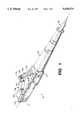
- FIG. 1is a rear, top and left-side perspective view of an embodiment in which the connector comprises a plug that terminates an optical cable and includes an anti-snag latch assembly;
- FIG. 2shows the connector of FIG. 1 inserted into a receptacle
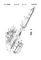
- FIG. 3is an exploded perspective view of the connector shown in FIG. 1, illustrating its associated components
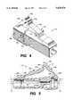
- FIG. 4is a front, top and right-side perspective view of a housing for the connector shown in FIG. 3;
- FIG. 5is a cross-section view of the housing for the connector shown in FIG. 3;
- FIG. 6is a side view of the connector installed within a receptacle, the latch being shown in its locked state;
- FIG. 7is a side view of the connector shown in FIG. 6, the latch being shown in its released state;
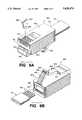
- FIG. 8Ais a front, bottom and left-side perspective view of an alternate embodiment in which the connector comprises a plug that terminates an electrical cable and includes an anti-snag latch assembly;
- FIG. 8Bis a rear, top and right side perspective view of the alternate embodiment shown in FIG. 8A.
- FIG. 9shows a front, top and right-side perspective view of a prior art electrical connector having anti-snag features.
- FIG. 1shows a rear, top and left-side perspective view of an optical fiber connector 10 which, together with bend-limiting strain-relief boot 20, terminates optical cable 30.
- Connector 10includes a plug end 12 which is inserted into a jack receptacle, and a cable-entrance end 13 which receives the optical cable.
- An optical connectionis made, for example, by butting the end face of ferrule 140 up against the end face of another ferrule which is precisely aligned with it.
- the outside surface of the connector 10includes a latch 120 for securing the connector to a jack receptacle in order to prevent unintended decoupling therebetween.
- Latch 120is molded into the connector and includes a "living hinge” which allows it to be moved up and down in a direction that is perpendicular to a central axis 101 of the connector (see FIG. 5).
- a trigger 130is molded into the connector and includes a living hinge which allows it to be moved up and down in a direction which is perpendicular to the central axis 101 of the connector.
- Latch 120 and trigger 130are cantilever beams whose longitudinal axes reside in the same plane that includes the central axis of the connector. Each of these cantilever beams includes a fixed end 125, 135 and a free end 124, 134; and their free ends are arranged to interact with each other.
- Trigger 130When trigger 130 is depressed, its free end 134 engages the free end 124 of latch 120 in order to release the connector 10 from a jack receptacle 40 (see FIG. 2).
- the free end of trigger 130is positioned above the free end of latch 120 so that when the trigger is depressed, its free end 134 slides over the free end 124 of the latch and urges it downward.
- the triggerfacilitates activation of the latch by effectively extending its length.
- Trigger 130extends in a direction which is parallel to the central axis of the connector, and can be made relatively narrow so that when connectors are positioned side-by-side in a dense array, each individual trigger can be manually accessed with minimum interference from an adjacent trigger. More importantly, the trigger 130 is sloped in a manner that prevents snagging when pulled backward (by cable 30) through a concentrated area of wires and cables.
- the connector 10has a footprint (cross-section dimension) of only 4.6 by 4.6 millimeters (mm), and a large number of such connectors can be grouped in a compact array.
- FIG. 2discloses a quadruplex jack receptacle 40 that accommodates up to four individual connectors 10.
- the front side of jack receptacle 40is shown protruding through panel 200 which may be of any particular shape. Receptacle 40 installs in a rectangular opening of the panel 200 by pushing its narrow end through the opening.
- the receptacleis held therein by latches 410, and may be removed from the panel by squeezing these latches and pushing the receptacle 40 toward the panel 200. Greater detail is presented in FIG. 6 and 7 regarding the manner in which a connector is held within, and removed from, a receptacle.
- FIG. 3is an exploded perspective view of the connector shown in FIG. 1, illustrating its associated components.
- FIG. 3discloses construction details of a connector 10 which includes housing 110, cover 100, and a fiber-holding structure comprising ferrule 140, base member 150, and spring 160 which is disposed about the base member.
- the fiber-holding structureis shown as a two-piece assembly, it can be a one-piece unit.
- Housing 110is a generally U-shaped structure having a first cavity 114 at its front end for receiving the fiber-holding structure, and having a second cavity 112 at its back end for receiving a flange 25 on a strain relief boot 20.
- the cover 100is joined to the housing 110 after the fiber-holding structure and the flange are installed therein.
- Cover 100includes snap features 106-108 that interlock with mating snap features 116-118 on housing 110. Once locked together, the front end of the connector has a generally square shape which fits into a receptacle 40 (FIG. 2) that is shaped to receive same.
- the connector 10includes a first opening 119 at its cable-entrance end 13 which receives an optical cable 30, and a second opening 111 at its plug end 12 for enabling the end face of the fiber-carrying structure to protrude therethrough. These openings 111, 119 respectively extend into cavities 114, 112 and are positioned at opposite ends of connector 10.
- Housing members 100, 110are molded from a thermoplastic material such as polycarbonate.
- the latch 120 and trigger 130are molded into the housing 110.
- Cylindrical ferrule 140is held within a mating opening of base member 150.
- a compression spring 160surrounds the back portion of the base member, and simultaneously presses against an interior surface 115 of the cavity 114 and the back side of a flange 152 on the base member.
- a chamfered surface 151 on the front side of flange 152cooperates with an inclined surface 113 within the cavity 114 to selectably seat the base member 150 within the housing 110 in one of six different stable positions.
- Compression spring 160urges the end face of ferrule 140 through opening 111.
- the ferrulemay be a glass, metal, ceramic or plastic cylinder having a narrow passageway (about 126 ⁇ m in diameter) through its central axis for receiving an end portion of an optical fiber.
- the ferrulehas an outer diameter of about 1.25 mm and a length of about 7.0 mm.
- a thin glass fiberis typically coated with two layers of ultraviolet-curable materials (polyacrylate for example) for protection.
- the coated fiberis then covered with a thermoplastic having sufficient stiffness to preclude fiber buckling and is referred to as a buffered fiber 33.
- the cableis constructed with a load-bearing portion in the form of strength members 32 that surround the buffered fiber.
- Elongated slender polymeric fibers of high tensile strength, such as aramid yam,are suitable for this purpose.
- An outer jacket 31comprising polyvinyl chloride, for example, surrounds the buffered fiber and strength members to complete the construction of optical cable 30. These layers of different materials are all stripped from the end portion of the glass fiber prior to its insertion into ferrule 140.
- An adhesiveis injected into the passageway through the central axis of ferrule 140. Then the uncoated portion of the optical fiber is inserted into the passageway of the ferrule and adhesively attached.
- the spring 160is pre-compressed on the ferrule/base member subassembly 140/150 with cable, and is inserted into housing 110. Additionally, strength members 32 of the cable 30 are folded back around flange 25 of the strain-relief boot 20 and an adhesive is applied thereto.
- a suitable adhesive for bonding the strength members to the connectoris Hysol 151--a commercially available, two-part epoxy.
- Flange 25is then pressed into cavity 112 at the back end of housing 110 so that the cable jacket 31 and the strength members 32 are "sandwiched" between the flange and the sidewalls of cavity 112.
- Cover 100is then snapped onto the housing. It is desirable that the cable 30 remain attached to connector 10 when an axial pull of at least 10 pounds is applied to cable 30.
- Strain-relief boot 20is about 38 mm long and is made from a suitably compliant material so that its back portion can be bent in a direction that is perpendicular to its central axis.
- the strain-relief bootis made from a thermoplastic rubber such as Santoprene® elastomer which is commercially available from Advanced Elastomer Systems, LP.
- Strain-relief boot 20is conically shaped and tapers from a maximum diameter of about 5.6 mm at one end 22 to a minimum diameter of about 3.0 mm at the other end 24. Not only does the boot 20 provide strain relief for cable 30, but it also insures that the cable can withstand repeated bends after interconnection without undue stress being imparted to the glass fiber.
- FIG. 4is a front, top and right-side perspective view of housing 110; and FIG. 5 is a cross section view of the housing.
- a resilient latchwhich is designated generally by the numeral 120.
- the latchis approximately 2.3 mm wide, 9.0 mm long, and has a minimum thickness of about 0.65 mm.
- the latch 120includes a pair of shoulders 121-121 which are positioned on its opposite sides.
- a resilient triggerwhich is designated generally by the numeral 130.
- the triggeris approximately 2.3 mm wide, 7.5 mm long, and has a minimum thickness of about 0.65 mm.
- Holes 163,164are molded into the side of housing 110 so it can be easily joined to another optical connector in a duplex or higher-order assembly.
- a clip(not shown) includes several pairs of pins, one pair being inserted into holes 163, 164 and another pair being inserted into another connector. In order to maintain proper polarization of the connectors, the holes 163, 164 have different diameters and can only be attached to the clip in one particular orientation.
- Housing 110further includes a reinforcement ledge 161 which cooperates with a mating recess 461 (FIG. 2) within the associated jack receptacle to keep the optical connector 10 from moving when a side load is applied to the connector.
- a similar reinforcement ledge 102is molded into the side of cover 100 (see FIG. 3) for the same purpose.
- latch 120comprises a cantilever beam having its fixed end 125 positioned toward the plug end of the housing 110, and its free end 124 positioned toward the cable-entrance end 13 of same.
- Latch 120is molded so that its longitudinal axis is oriented at an angle ⁇ (approximately 15°) with respect to the central axis 101 of the housing 110.
- the region 126 where the latch meets the top surface of the housinghas a radius of curvature of approximately 0.25 mm.
- Trigger 130comprises a cantilever beam having its fixed end 135 positioned toward the cable-entrance end 13 of the housing 110, and its free end 134 positioned toward the plug end 12 of same.
- the free end of the triggerincludes a protruding surface 132 that assists in operating the trigger.
- Surface 132enhances the manual operation of the trigger 130, enabling it to be easily operated in a high density application, either manually or with the tip of a pen.
- surface 132includes a plurality of ridges.
- Trigger 130is molded so that its longitudinal axis is oriented at an angle ⁇ (approximately 50°) with respect to the central axis 101 of housing 110.
- the region 136 where the trigger meets the top surface of the housinghas a radius of curvature of approximately 0.25 mm.
- the bottom side of trigger 130includes a camming surface 133 which slides along a surface 123 of the latch 120 when the trigger is pressed downward.
- camming surface 133is preferably shaped like the letter "S,” it is understood that other shapes are effective in the practice of the invention.
- latch 120facilitates insertion of connector 10 into a jack receptacle 60.
- the latch 120essentially resumes its original molded shape and orientation because of its natural resilience.
- latch 120which moves downward while being inserted into a simplex jack receptacle 60, but then springs back (upwardly) after insertion is complete.
- the downward movement of the latchis caused by interference (during insertion) between shoulder 121 on the latch and a tapered surface within the receptacle.
- vertical surface 632 within the receptacleinteracts with vertical surface 122 on the shoulder 121 of the latch 120 to lock the connector 10 into the receptacle 60.
- a panel-mounting latch 610is positioned on the top and bottom sides of receptacle 60, and includes a tapered surface 611 for capturing panels of different thickness between the tapered surface and flange 612.
- FIG. 8A-8Bdisclose front and rear perspective views of an alternate embodiment of the present invention in which the anti-snag feature is applied to an electrical connector and, more particularly, is applied to an R J-type modular plug. And while a brief description of the construction and operation of such an electrical connector is included for clarity, greater detail is provided in U.S. Pat. No. 3,860,316 which is hereby incorporated by reference.
- a rigid, dielectric housingdesignated generally by the numeral 800, is designed to be easily molded by using conventional injection-molding techniques.
- Housing 800has a free end 82, a cord-input end 83, and a terminal-receiving side 803.
- the housingis formed with a cord input aperture 805 which circumscribes the end portion of cord 80 which extends therethrough.
- the aperture 805has a flared entrance which protects cord 80, increases its life, and facilitates insertion.
- the apertureopens into a cavity 806 which partially terminates in a ledge 807 at the free end 82 of the housing.
- housing 800is a unipartite structure in which the interior cavity is formed during molding a substantially encloses an end portion of the cord which is inserted into the aperture.
- a plurality of conductor-receiving troughs 802--802are designed to receive associated ones of the conductors 801--801.
- the center-to-center distance between troughsis, illustratively, 1.0 mm (0.040 inches).
- the bottoms of troughs 802--802are substantially coplanar with the top surface of ledge 807 at the free end 82. This facilitates the use of the ledge as an anvil for conductor cut-off during assembly of the housing 800 to the cord 80.
- the terminal-inserting side 803 of the housingis primarily shown in FIG. 8A and, illustratively, includes six slots, each slot 815 receiving a conductive terminal 850 made from a resilient material such as phosphor bronze.
- Each terminal 850includes one contact portion 851 for making electrical contact external to the housing, and another contact portion 852 that extends into trough 802 for piercing the insulation of a conductor 801 residing therein, and making electrical engagement with an internal copper wire.
- Contact portion 852illustratively comprises a plurality of tangs.
- Terminal-receiving slots 815each include an opening (not shown) which extends into an associated conductor-receiving trough 802.
- the latching side 804 of the housingis primarily shown in FIG. 8B and includes a latch 820 and a trigger 830. These are cantilever beams whose fixed ends are located at opposite ends of the housing 800, and whose free ends are generally in the center of the housing. When a user depresses the free end 834 and pulls rearwardly on surface 832 of the trigger 830, its underside presses against the free end 824 of the latch 820 and moves it downward--thereby moving locking shoulder 821 so that the housing 800 can be withdrawn from a jack receptacle into which it may be inserted.
- FIG. 9discloses a front, top and right-side perspective view of a prior art electrical connector 900 having anti-snag features.
- an RJ-type modular plugis disclosed having a pair of rigid sidewalls 930 integrally molded into the housing.
- Such a plugis incidentally shown in U.S. Pat. No. 4,611,875 issued on Sep. 16, 1986 to Clarke et al.
- the sidewallsare tapered toward the cord-input end so that when it is pulled by the cord 90, its locking tab 920 will not snag other wires and cables along its path.
- the sidewallsneed to be about the same height as the free end of tab 920 to prevent snagging. However, this tends to make the tab somewhat difficult for a user to manually operate, which is particularly true for smaller connectors.
Landscapes
- Physics & Mathematics (AREA)
- General Physics & Mathematics (AREA)
- Optics & Photonics (AREA)
- Mechanical Coupling Of Light Guides (AREA)
- Details Of Connecting Devices For Male And Female Coupling (AREA)
- Connector Housings Or Holding Contact Members (AREA)
Abstract
Description
Claims (16)
Priority Applications (11)
| Application Number | Priority Date | Filing Date | Title |
|---|---|---|---|
| US08/520,808US5638474A (en) | 1995-08-30 | 1995-08-30 | Anti-snag latch assembly for a connector |
| CA002180187ACA2180187C (en) | 1995-08-30 | 1996-06-28 | Anti-snag latch assembly for a connector |
| TW085108015ATW301812B (en) | 1995-08-30 | 1996-07-02 | |
| DE69610961TDE69610961T2 (en) | 1995-08-30 | 1996-08-21 | Interlocking locking device for a connector |
| EP96306101AEP0762558B1 (en) | 1995-08-30 | 1996-08-21 | Anti-snag latch assembly for a connector |
| AU64267/96AAU699140B2 (en) | 1995-08-30 | 1996-08-26 | Anti-snag latch assembly for a connector |
| MYPI96003523AMY113138A (en) | 1995-08-30 | 1996-08-26 | Anti-snag latch assembly for a connector |
| MX9603671AMX9603671A (en) | 1995-08-30 | 1996-08-27 | ANTI-HITCH LOCK ASSEMBLY FOR ONE CONNECTOR. |
| KR1019960036228AKR100245144B1 (en) | 1995-08-30 | 1996-08-29 | A connector comprising a latching latch assembly |
| CN96111433ACN1090400C (en) | 1995-08-30 | 1996-08-29 | Anti-snag latch assembly for connector |
| JP8228334AJPH09113762A (en) | 1995-08-30 | 1996-08-29 | connector |
Applications Claiming Priority (1)
| Application Number | Priority Date | Filing Date | Title |
|---|---|---|---|
| US08/520,808US5638474A (en) | 1995-08-30 | 1995-08-30 | Anti-snag latch assembly for a connector |
Publications (1)
| Publication Number | Publication Date |
|---|---|
| US5638474Atrue US5638474A (en) | 1997-06-10 |
Family
ID=24074161
Family Applications (1)
| Application Number | Title | Priority Date | Filing Date |
|---|---|---|---|
| US08/520,808Expired - LifetimeUS5638474A (en) | 1995-08-30 | 1995-08-30 | Anti-snag latch assembly for a connector |
Country Status (11)
| Country | Link |
|---|---|
| US (1) | US5638474A (en) |
| EP (1) | EP0762558B1 (en) |
| JP (1) | JPH09113762A (en) |
| KR (1) | KR100245144B1 (en) |
| CN (1) | CN1090400C (en) |
| AU (1) | AU699140B2 (en) |
| CA (1) | CA2180187C (en) |
| DE (1) | DE69610961T2 (en) |
| MX (1) | MX9603671A (en) |
| MY (1) | MY113138A (en) |
| TW (1) | TW301812B (en) |
Cited By (124)
| Publication number | Priority date | Publication date | Assignee | Title |
|---|---|---|---|---|
| US5850499A (en)* | 1996-10-16 | 1998-12-15 | Japan Recom Ltd. | Locking closure for optical fiber cable connection |
| US5915056A (en)* | 1997-08-06 | 1999-06-22 | Lucent Technologies Inc. | Optical fiber strain relief device |
| US5993236A (en)* | 1995-09-29 | 1999-11-30 | Panduit Corp. | Tangle-free modular plug connector |
| US6104856A (en)* | 1998-06-16 | 2000-08-15 | Lucent Technologies Inc. | Optical air-gap attenuator |
| US6102581A (en)* | 1998-06-16 | 2000-08-15 | Lucent Technologies Inc. | Optical adapter including a ferrule assembly |
| US6196733B1 (en) | 1999-06-08 | 2001-03-06 | Lucent Technologies Inc. | Strain relief apparatus for optical connector |
| US6250817B1 (en)* | 1999-10-19 | 2001-06-26 | Lucent Technologies Inc. | Device that attaches to the boot of an optical fiber simplex connector to provide the connector with anti-snagging and/or polarity identification features |
| US6287018B1 (en) | 1999-07-28 | 2001-09-11 | Lucent Technologies Inc. | Tunable optical fiber connector |
| US6357934B1 (en) | 2000-01-27 | 2002-03-19 | Lucent Technologies Inc. | Optical fiber boot for a connector that provides anti-snagging and polarity identification |
| US6357933B1 (en) | 1999-03-30 | 2002-03-19 | Lucent Technologies Inc. | Quick connect optical fiber ferrule connector |
| US6443627B1 (en)* | 2001-01-10 | 2002-09-03 | Fitel Usa Corp. | Duplex optical connector |
| US6454464B1 (en) | 1998-12-28 | 2002-09-24 | Computer Crafts, Inc. | Fiber optic connectors and transceiver test devices |
| US6456768B1 (en) | 2000-10-18 | 2002-09-24 | Fitel Usa Corp. | Optical fiber cable tracing system |
| US6464408B1 (en) | 1998-12-28 | 2002-10-15 | Computer Crafts, Inc. | Fiber optic connectors |
| US6543941B1 (en) | 2000-10-18 | 2003-04-08 | Fitel Usa Corp. | Jack receptacle having optical and electrical ports |
| US6547450B2 (en) | 2001-06-27 | 2003-04-15 | Fitel Usa Corp. | Quick-release dust cap for an optical plug |
| US6550979B1 (en) | 2001-10-19 | 2003-04-22 | Corning Cable Systems Llc | Floating connector subassembly and connector including same |
| US6565262B2 (en)* | 2000-12-14 | 2003-05-20 | Corning Cable Systems Llc | Trigger mechanism, optical cable connector including same, and method of assembling an optical cable connector |
| US6588938B1 (en) | 2000-10-18 | 2003-07-08 | Fitel Usa Corp. | Optical/electrical plug connector |
| US6609837B2 (en) | 2001-04-27 | 2003-08-26 | Fitel Usa Corp. | Optical fiber adapter for dissimilar size ferrules |
| US6672774B2 (en) | 2001-10-05 | 2004-01-06 | Corning Cable Systems Llc | Post-connectorization boot, connectorized fiber optic cable assembly including same, and related methods |
| US6752538B1 (en)* | 2003-02-24 | 2004-06-22 | Itt Manufacturing Enterprises, Inc. | Optic fiber connector secondary latch |
| US20040166716A1 (en)* | 2003-02-21 | 2004-08-26 | Alcatel | Device for hooking/unhooking LC connectors |
| US20040247252A1 (en)* | 2003-02-28 | 2004-12-09 | John Ehrenreich | Retractable fiber optic connector housing |
| USD501130S1 (en) | 2003-12-17 | 2005-01-25 | Southco, Inc. | Double catch-ejector latch |
| US20050082840A1 (en)* | 2003-05-12 | 2005-04-21 | Sumitomo Wiring Systems, Ltd. | Connector locking construction |
| US20050136715A1 (en)* | 2003-12-17 | 2005-06-23 | Schlack Richard E. | Ejector latch with double catch |
| US20050169583A1 (en)* | 1997-05-20 | 2005-08-04 | Adc Telecommunications, Inc. | Fiber connector and adapter |
| US20050208816A1 (en)* | 2004-03-19 | 2005-09-22 | Hubbell Incorporated | Snagless telecommunications plug assembly |
| US20050213891A1 (en)* | 2004-03-26 | 2005-09-29 | Hardcastle David S | Small form factor optical connector with thermoplastic adhesive |
| US7101212B1 (en)* | 2005-03-07 | 2006-09-05 | Kevin Larkin | Snagless plug and boot connection |
| US20060263011A1 (en)* | 2005-05-20 | 2006-11-23 | Wenzong Chen | Hybrid optical/electrical connector and adapter |
| US20070011857A1 (en)* | 2005-07-13 | 2007-01-18 | Lucent Technologies Inc. | Electrical connector extraction and/or insertion tool |
| US20070172173A1 (en)* | 2003-09-17 | 2007-07-26 | Adc Gmbh | Housing for fiber-optic plug-in connector, and a method for laying fiber-optic cables |
| US20080025670A1 (en)* | 2006-07-31 | 2008-01-31 | Tyco Electronics Corporation | Strain relief boot for cable connector |
| US20080175542A1 (en)* | 2007-01-24 | 2008-07-24 | Yu Lu | Hardened fiber optic adapter |
| US20080248682A1 (en)* | 2007-04-06 | 2008-10-09 | Kevin Larkin | Snagless plug and boot connection |
| US7527515B1 (en) | 2008-07-09 | 2009-05-05 | Metrologic Instruments, Inc. | Cable connector release |
| US20090148101A1 (en)* | 2007-12-11 | 2009-06-11 | Yu Lu | Hardened Fiber Optic Connection System with Multiple Configurations |
| US7572065B2 (en) | 2007-01-24 | 2009-08-11 | Adc Telecommunications, Inc. | Hardened fiber optic connector |
| US7588373B1 (en)* | 2008-07-16 | 2009-09-15 | Sanwa Denki Kogyo Co., Ltd. | Optical connector plug |
| US20090253305A1 (en)* | 2008-04-02 | 2009-10-08 | International Business Machines Corporation | Replacement clip and method for repairing a modular cable connector having a broken locking clip |
| US20090269014A1 (en)* | 2008-04-25 | 2009-10-29 | Winberg Paul N | Field terminable lc format optical connector with splice element |
| US20090298350A1 (en)* | 2006-03-17 | 2009-12-03 | Moeller Gmbh | Plug arrangement for an electric or optical cable |
| US20090310916A1 (en)* | 2006-08-15 | 2009-12-17 | Luther James P | Ruggedized Fiber Optic Connector Assembly |
| US20090310928A1 (en)* | 2008-06-12 | 2009-12-17 | Wolf Kluwe | Universal cable bracket |
| US7695198B1 (en) | 2009-03-30 | 2010-04-13 | Tyco Electronics Corporation | Latch protection clip for a connector |
| US20100124845A1 (en)* | 2008-11-18 | 2010-05-20 | Hon Hai Precision Ind. Co., Ltd. | Cable assembly having enhanced interconnection means thereof |
| USD619100S1 (en) | 2009-10-21 | 2010-07-06 | 3M Innovative Properties Company | Latch for an optical fiber connector |
| US20110091159A1 (en)* | 2009-10-15 | 2011-04-21 | De Jong Michael | Push-Pull Fiber Optic Connectors and Methods for Making the Same |
| US20110140856A1 (en)* | 2009-11-30 | 2011-06-16 | John David Downie | RFID Condition Latching |
| USRE42522E1 (en) | 2003-09-08 | 2011-07-05 | Adc Telecommunications, Inc. | Ruggedized fiber optic connection |
| US8025514B1 (en) | 2010-04-23 | 2011-09-27 | Leviton Manufacturing Co., Inc. | Shroud to prevent manipulation of a release mechanism of a plug |
| DE112009002433T5 (en) | 2008-09-29 | 2011-09-29 | Corning Cable Systems Llc | Assembly for a fiber optic connector with wired RFID antenna |
| US8038456B1 (en) | 2010-04-23 | 2011-10-18 | Leviton Manufacturing Co., Inc | Tamper prevention system having a shroud to partially cover a release mechanism |
| CN101478095B (en)* | 2009-02-16 | 2012-08-29 | 中航光电科技股份有限公司 | Anti-drop connector |
| US20120274452A1 (en)* | 2011-04-26 | 2012-11-01 | Aravind Chamarti | Radio frequency (rf)-enabled latches and related components, assemblies, systems, and methods |
| US8433171B2 (en) | 2009-06-19 | 2013-04-30 | Corning Cable Systems Llc | High fiber optic cable packing density apparatus |
| US8538226B2 (en) | 2009-05-21 | 2013-09-17 | Corning Cable Systems Llc | Fiber optic equipment guides and rails configured with stopping position(s), and related equipment and methods |
| US8542973B2 (en) | 2010-04-23 | 2013-09-24 | Ccs Technology, Inc. | Fiber optic distribution device |
| US8556645B2 (en) | 2012-01-23 | 2013-10-15 | Commscope, Inc. Of North Carolina | Delatching connector including extension member |
| US8593828B2 (en) | 2010-02-04 | 2013-11-26 | Corning Cable Systems Llc | Communications equipment housings, assemblies, and related alignment features and methods |
| US8625950B2 (en) | 2009-12-18 | 2014-01-07 | Corning Cable Systems Llc | Rotary locking apparatus for fiber optic equipment trays and related methods |
| US8660397B2 (en) | 2010-04-30 | 2014-02-25 | Corning Cable Systems Llc | Multi-layer module |
| US8662760B2 (en) | 2010-10-29 | 2014-03-04 | Corning Cable Systems Llc | Fiber optic connector employing optical fiber guide member |
| US8699838B2 (en) | 2009-05-14 | 2014-04-15 | Ccs Technology, Inc. | Fiber optic furcation module |
| US8705926B2 (en) | 2010-04-30 | 2014-04-22 | Corning Optical Communications LLC | Fiber optic housings having a removable top, and related components and methods |
| US8712206B2 (en) | 2009-06-19 | 2014-04-29 | Corning Cable Systems Llc | High-density fiber optic modules and module housings and related equipment |
| US8718436B2 (en) | 2010-08-30 | 2014-05-06 | Corning Cable Systems Llc | Methods, apparatuses for providing secure fiber optic connections |
| US8747141B2 (en) | 2012-01-23 | 2014-06-10 | Commscope, Inc. Of North Carolina | Delatching connector including extension member |
| US8753022B2 (en) | 2010-11-30 | 2014-06-17 | Adc Telecommunications, Inc. | LC connector and method of assembly |
| US8764308B2 (en) | 2011-06-06 | 2014-07-01 | Panduit Corp. | Duplex clip assembly for fiber optic connectors |
| US20140241690A1 (en)* | 2013-02-23 | 2014-08-28 | Ezontek Technologies Co., Ltd. | Optical fiber adapter |
| US20140302699A1 (en)* | 2013-04-09 | 2014-10-09 | Molex Incorporated | Electrical connection device |
| US8879881B2 (en) | 2010-04-30 | 2014-11-04 | Corning Cable Systems Llc | Rotatable routing guide and assembly |
| US8876405B2 (en) | 2011-06-27 | 2014-11-04 | 3M Innovative Properties Company | Field terminable optical connector with splice element for jacketed cable |
| US8913866B2 (en) | 2010-03-26 | 2014-12-16 | Corning Cable Systems Llc | Movable adapter panel |
| US8939655B2 (en) | 2012-06-29 | 2015-01-27 | Corning Cable Systems Llc | Dust caps, fiber optic connectors, and fiber optic splitter modules incorporating interlocking key features |
| US8953924B2 (en) | 2011-09-02 | 2015-02-10 | Corning Cable Systems Llc | Removable strain relief brackets for securing fiber optic cables and/or optical fibers to fiber optic equipment, and related assemblies and methods |
| US8985862B2 (en) | 2013-02-28 | 2015-03-24 | Corning Cable Systems Llc | High-density multi-fiber adapter housings |
| US8989547B2 (en) | 2011-06-30 | 2015-03-24 | Corning Cable Systems Llc | Fiber optic equipment assemblies employing non-U-width-sized housings and related methods |
| US8995812B2 (en) | 2012-10-26 | 2015-03-31 | Ccs Technology, Inc. | Fiber optic management unit and fiber optic distribution device |
| US9008485B2 (en) | 2011-05-09 | 2015-04-14 | Corning Cable Systems Llc | Attachment mechanisms employed to attach a rear housing section to a fiber optic housing, and related assemblies and methods |
| US9020320B2 (en) | 2008-08-29 | 2015-04-28 | Corning Cable Systems Llc | High density and bandwidth fiber optic apparatuses and related equipment and methods |
| US9022814B2 (en) | 2010-04-16 | 2015-05-05 | Ccs Technology, Inc. | Sealing and strain relief device for data cables |
| US20150131085A1 (en)* | 2013-11-11 | 2015-05-14 | Bi Incorporated | Systems and Methods for Reducing False Negative Tamper Detection |
| US9042702B2 (en) | 2012-09-18 | 2015-05-26 | Corning Cable Systems Llc | Platforms and systems for fiber optic cable attachment |
| US9038832B2 (en) | 2011-11-30 | 2015-05-26 | Corning Cable Systems Llc | Adapter panel support assembly |
| US9052469B2 (en) | 2013-04-26 | 2015-06-09 | Corning Cable Systems Llc | Preterminated fiber optic connector sub-assemblies, and related fiber optic connectors, cable assemblies, and methods |
| US9059578B2 (en) | 2009-02-24 | 2015-06-16 | Ccs Technology, Inc. | Holding device for a cable or an assembly for use with a cable |
| US9075217B2 (en) | 2010-04-30 | 2015-07-07 | Corning Cable Systems Llc | Apparatuses and related components and methods for expanding capacity of fiber optic housings |
| US9075216B2 (en) | 2009-05-21 | 2015-07-07 | Corning Cable Systems Llc | Fiber optic housings configured to accommodate fiber optic modules/cassettes and fiber optic panels, and related components and methods |
| US9146362B2 (en) | 2012-09-21 | 2015-09-29 | Adc Telecommunications, Inc. | Insertion and removal tool for a fiber optic ferrule alignment sleeve |
| US9165232B2 (en) | 2012-05-14 | 2015-10-20 | Corning Incorporated | Radio-frequency identification (RFID) tag-to-tag autoconnect discovery, and related methods, circuits, and systems |
| CN105093423A (en)* | 2014-05-12 | 2015-11-25 | 昆山迎翔光电科技有限公司 | LC type fiber connector |
| US9213161B2 (en) | 2010-11-05 | 2015-12-15 | Corning Cable Systems Llc | Fiber body holder and strain relief device |
| US9250409B2 (en) | 2012-07-02 | 2016-02-02 | Corning Cable Systems Llc | Fiber-optic-module trays and drawers for fiber-optic equipment |
| US9279951B2 (en) | 2010-10-27 | 2016-03-08 | Corning Cable Systems Llc | Fiber optic module for limited space applications having a partially sealed module sub-assembly |
| US9448370B2 (en) | 2012-02-20 | 2016-09-20 | Commscope Technologies Llc | Connector and connector assembly |
| US20160327756A1 (en)* | 2015-05-06 | 2016-11-10 | Fibrefab Limited | Fibre optic cable assembly |
| US9519118B2 (en) | 2010-04-30 | 2016-12-13 | Corning Optical Communications LLC | Removable fiber management sections for fiber optic housings, and related components and methods |
| US9632270B2 (en) | 2010-04-30 | 2017-04-25 | Corning Optical Communications LLC | Fiber optic housings configured for tool-less assembly, and related components and methods |
| US9640910B1 (en) | 2016-05-02 | 2017-05-02 | Dell Products L.P. | Apparatus for securing connection between cable assembly and storage device connector |
| US9645317B2 (en) | 2011-02-02 | 2017-05-09 | Corning Optical Communications LLC | Optical backplane extension modules, and related assemblies suitable for establishing optical connections to information processing modules disposed in equipment racks |
| US9720195B2 (en) | 2010-04-30 | 2017-08-01 | Corning Optical Communications LLC | Apparatuses and related components and methods for attachment and release of fiber optic housings to and from an equipment rack |
| US9761998B2 (en) | 2011-02-08 | 2017-09-12 | Commscope Technologies Llc | Release tab for an electrical connector and electrical connector comprising said release tab |
| US9823428B1 (en) | 2017-01-25 | 2017-11-21 | Fluke Corporation | Optical connector and duplex connector assembly |
| US9825403B2 (en) | 2011-02-08 | 2017-11-21 | Commscope Technologies Llc | RJ type connector including a disengagement feature acting on the latch of the connector |
| US9941631B1 (en) | 2017-06-29 | 2018-04-10 | Seikoh Giken Co., Ltd. | Plug and cable with plug |
| US10040067B2 (en) | 2014-11-10 | 2018-08-07 | Leibniz-Institut für Naturstoff-Forschung und Infektionsbiologie—Hans-Knöll-Institut | Device and method for extracting individual picoliter droplets from microfluidic emulsions for further analysis and scale-up |
| US10067301B2 (en) | 2014-01-13 | 2018-09-04 | Commscope Connectivity Uk Limited | Fiber optic connector |
| US10094996B2 (en) | 2008-08-29 | 2018-10-09 | Corning Optical Communications, Llc | Independently translatable modules and fiber optic equipment trays in fiber optic equipment |
| US10120140B2 (en) | 2017-01-25 | 2018-11-06 | Fluke Corporation | Connector and duplex connector assembly |
| US10302874B2 (en) | 2015-05-15 | 2019-05-28 | Commscope Telecommunications (Shanghai) Co., Ltd. | Alignment sleeve assembly and fiber optic adapter |
| US10444443B2 (en) | 2013-06-27 | 2019-10-15 | CommScope Connectivity Belgium BVBA | Fiber optic cable anchoring device for use with fiber optic connectors and methods of using the same |
| US10745660B2 (en) | 2014-11-10 | 2020-08-18 | Leibniz-Institut Fur Naturstoff-Forschung Und Infektionsbiologie—Hans-Knöll-Institut | System for incubating microfluidic droplets and method for producing homogeneous incubation conditions in a droplet incubation unit |
| JP2021140126A (en)* | 2020-03-05 | 2021-09-16 | 株式会社精工技研 | Jig for connector plug, connector plug, cable with connector plug |
| US11181696B2 (en)* | 2019-02-22 | 2021-11-23 | Senko Advanced Components, Inc. | Adapter assembly having a return spring with a push-pull tab |
| US11215767B2 (en) | 2017-06-07 | 2022-01-04 | Commscope Technologies Llc | Fiber optic adapter and cassette |
| US11294135B2 (en) | 2008-08-29 | 2022-04-05 | Corning Optical Communications LLC | High density and bandwidth fiber optic apparatuses and related equipment and methods |
| US11327240B2 (en) | 2017-09-15 | 2022-05-10 | Commscope Technologies Llc | Fiber optic connector with boot-integrated release and related assemblies |
| US20220224046A1 (en)* | 2021-01-08 | 2022-07-14 | Sumitomo Wiring Systems, Ltd. | Connector and connector device |
| US11454767B2 (en)* | 2018-10-10 | 2022-09-27 | Senko Advanced Components, Inc. | Multi-polarity fiber optic connector having a duplex cable boot assembly |
| US12345925B2 (en) | 2020-05-29 | 2025-07-01 | Commscope Technologies Llc | Telecommunications connector with latch release mechanism |
Families Citing this family (20)
| Publication number | Priority date | Publication date | Assignee | Title |
|---|---|---|---|---|
| JPH11185874A (en)* | 1997-12-19 | 1999-07-09 | Yazaki Corp | Connector lock arm protection structure |
| DE69900597T2 (en)* | 1998-03-13 | 2002-08-01 | Framatome Connectors International, Courbevoie | CONNECTOR WITH SECONDARY LOCKING MECHANISM |
| US6130977A (en)* | 1998-07-17 | 2000-10-10 | Siecor Operations, Llc | Fiber optic connector sleeve having positioning ribs |
| US6422760B1 (en)* | 2001-01-31 | 2002-07-23 | Molex Incorporated | Fiber optic connector module |
| US6652155B2 (en)* | 2001-06-21 | 2003-11-25 | Fitel Usa Corp. | Optical connector plug |
| US6811445B2 (en)* | 2002-04-22 | 2004-11-02 | Panduit Corp. | Modular cable termination plug |
| NZ518704A (en)* | 2002-05-03 | 2004-11-26 | Auckland Uniservices Ltd | Connector set where the pins are angled, such that a pull force on the cables result in a stronger connection |
| JP2005166522A (en)* | 2003-12-04 | 2005-06-23 | Yazaki Corp | connector |
| JP2006267649A (en) | 2005-03-24 | 2006-10-05 | Seikoh Giken Co Ltd | Optical connector |
| JP4658774B2 (en)* | 2005-10-28 | 2011-03-23 | 日立電線株式会社 | Optical connector |
| SG137710A1 (en) | 2006-05-11 | 2007-12-28 | Volex Asia Pte Ltd | Positive lock connector |
| DK2664951T3 (en) | 2008-05-07 | 2016-09-19 | Huber + Suhner Ag | Plug connector with unlocking |
| DE202009019167U1 (en) | 2008-05-07 | 2017-06-06 | Huber + Suhner Ag | Connector with unlocking |
| TWI406457B (en)* | 2009-10-08 | 2013-08-21 | Aimmet Ind Co Ltd | Connector structure (5) |
| US8529284B1 (en)* | 2012-04-25 | 2013-09-10 | Quality Computer Accessories Inc. | Connector locking assembly |
| CN110031939B (en)* | 2016-12-05 | 2020-06-09 | 扇港元器件股份有限公司 | Narrow Width Adapters and Connectors with Modular Latch Arms |
| JP7080853B2 (en)* | 2019-06-25 | 2022-06-06 | 三菱電機システムサービス株式会社 | connector |
| TWI784427B (en)* | 2020-11-13 | 2022-11-21 | 立佳興業股份有限公司 | Optical-electrical connector |
| CN112764169B (en)* | 2021-02-25 | 2025-01-24 | 武汉邮埃服光电科技有限公司 | Optical fiber connector and optical fiber connection structure |
| CN116581586B (en)* | 2023-05-12 | 2023-11-10 | 东莞市思索技术股份有限公司 | Power connector |
Citations (7)
| Publication number | Priority date | Publication date | Assignee | Title |
|---|---|---|---|---|
| US3860316A (en)* | 1973-07-06 | 1975-01-14 | Western Electric Co | Electrical connecting devices for terminating cords and methods of assembling the devices to cords |
| US4241974A (en)* | 1979-05-02 | 1980-12-30 | Western Electric Company, Inc. | Multi-outlet adapter for modular telephone cords |
| US4611875A (en)* | 1984-08-23 | 1986-09-16 | At&T Information Systems | Communication system cross-connect field power adapter |
| US5224186A (en)* | 1991-05-29 | 1993-06-29 | Sumitomo Electric Industries, Ltd. | Optical fiber connector with housing assembly for an assuring complete connection |
| US5419717A (en)* | 1994-08-15 | 1995-05-30 | The Whitaker Corporation | Hybrid connector between optics and edge card |
| US5461690A (en)* | 1994-07-29 | 1995-10-24 | At&T Ipm Corp. | Bend-limiting apparatus for a cable |
| US5481634A (en)* | 1994-06-24 | 1996-01-02 | At&T Corp. | Connector for optical fiber |
Family Cites Families (3)
| Publication number | Priority date | Publication date | Assignee | Title |
|---|---|---|---|---|
| DE3526353A1 (en)* | 1985-07-23 | 1987-02-05 | Siemens Ag | CABLE PLUG WITH A SNAP DEVICE |
| US5334044A (en)* | 1993-05-27 | 1994-08-02 | Aldo Falossi | Radio jack strain relief and identification holder |
| FR2720868B1 (en)* | 1994-06-02 | 1996-08-02 | Logistel | Improvements to the assembly of electrical connection members. |
- 1995
- 1995-08-30USUS08/520,808patent/US5638474A/ennot_activeExpired - Lifetime
- 1996
- 1996-06-28CACA002180187Apatent/CA2180187C/ennot_activeExpired - Fee Related
- 1996-07-02TWTW085108015Apatent/TW301812B/zhactive
- 1996-08-21EPEP96306101Apatent/EP0762558B1/ennot_activeExpired - Lifetime
- 1996-08-21DEDE69610961Tpatent/DE69610961T2/ennot_activeExpired - Lifetime
- 1996-08-26MYMYPI96003523Apatent/MY113138A/enunknown
- 1996-08-26AUAU64267/96Apatent/AU699140B2/ennot_activeExpired
- 1996-08-27MXMX9603671Apatent/MX9603671A/enunknown
- 1996-08-29CNCN96111433Apatent/CN1090400C/ennot_activeExpired - Lifetime
- 1996-08-29JPJP8228334Apatent/JPH09113762A/enactivePending
- 1996-08-29KRKR1019960036228Apatent/KR100245144B1/ennot_activeExpired - Fee Related
Patent Citations (7)
| Publication number | Priority date | Publication date | Assignee | Title |
|---|---|---|---|---|
| US3860316A (en)* | 1973-07-06 | 1975-01-14 | Western Electric Co | Electrical connecting devices for terminating cords and methods of assembling the devices to cords |
| US4241974A (en)* | 1979-05-02 | 1980-12-30 | Western Electric Company, Inc. | Multi-outlet adapter for modular telephone cords |
| US4611875A (en)* | 1984-08-23 | 1986-09-16 | At&T Information Systems | Communication system cross-connect field power adapter |
| US5224186A (en)* | 1991-05-29 | 1993-06-29 | Sumitomo Electric Industries, Ltd. | Optical fiber connector with housing assembly for an assuring complete connection |
| US5481634A (en)* | 1994-06-24 | 1996-01-02 | At&T Corp. | Connector for optical fiber |
| US5461690A (en)* | 1994-07-29 | 1995-10-24 | At&T Ipm Corp. | Bend-limiting apparatus for a cable |
| US5419717A (en)* | 1994-08-15 | 1995-05-30 | The Whitaker Corporation | Hybrid connector between optics and edge card |
Cited By (228)
| Publication number | Priority date | Publication date | Assignee | Title |
|---|---|---|---|---|
| US5993236A (en)* | 1995-09-29 | 1999-11-30 | Panduit Corp. | Tangle-free modular plug connector |
| US5850499A (en)* | 1996-10-16 | 1998-12-15 | Japan Recom Ltd. | Locking closure for optical fiber cable connection |
| US8870466B2 (en) | 1997-05-20 | 2014-10-28 | Adc Telecommunications, Inc. | Fiber connector and adapter |
| US20050169583A1 (en)* | 1997-05-20 | 2005-08-04 | Adc Telecommunications, Inc. | Fiber connector and adapter |
| US20100195958A1 (en)* | 1997-05-20 | 2010-08-05 | Adc Telecommunications, Inc. | Fiber connector and adapter |
| US7874738B2 (en) | 1997-05-20 | 2011-01-25 | Adc Telecommunications, Inc. | Fiber connector and adapter |
| US8186890B2 (en) | 1997-05-20 | 2012-05-29 | Adc Telecommunications, Inc. | Fiber connector and adapter |
| US7384201B2 (en) | 1997-05-20 | 2008-06-10 | Adc Telecommunications, Inc. | Fiber connector and adapter |
| US7654749B2 (en) | 1997-05-20 | 2010-02-02 | Adc Telecommunications, Inc. | Fiber connector and adapter |
| US9383524B2 (en) | 1997-05-20 | 2016-07-05 | Commscope Technologies Llc | Fiber connector and adapter |
| US7503702B2 (en) | 1997-05-20 | 2009-03-17 | Adc Telecommunications, Inc. | Fiber connector and adapter |
| US20070253666A1 (en)* | 1997-05-20 | 2007-11-01 | Adc Telecommunications, Inc. | Fiber connector and adapter |
| US20080279507A1 (en)* | 1997-05-20 | 2008-11-13 | Adc Telecommunications, Inc. | Fiber connector and adapter |
| US20070086706A1 (en)* | 1997-05-20 | 2007-04-19 | Adc Telecommunications, Inc. | Fiber connector and adapter |
| US7246950B2 (en) | 1997-05-20 | 2007-07-24 | Adc Telecommunications, Inc. | Fiber connector and adapter |
| US7118288B2 (en) | 1997-05-20 | 2006-10-10 | Adc Telecommunications, Inc. | Fiber connector and adapter |
| US20090199398A1 (en)* | 1997-05-20 | 2009-08-13 | Adc Telecommunications, Inc | Fiber connector and adapter |
| US5915056A (en)* | 1997-08-06 | 1999-06-22 | Lucent Technologies Inc. | Optical fiber strain relief device |
| US6104856A (en)* | 1998-06-16 | 2000-08-15 | Lucent Technologies Inc. | Optical air-gap attenuator |
| US6102581A (en)* | 1998-06-16 | 2000-08-15 | Lucent Technologies Inc. | Optical adapter including a ferrule assembly |
| US6554487B2 (en) | 1998-12-28 | 2003-04-29 | Computer Crafts, Inc. | Fiber optic connectors |
| US6464408B1 (en) | 1998-12-28 | 2002-10-15 | Computer Crafts, Inc. | Fiber optic connectors |
| US6454464B1 (en) | 1998-12-28 | 2002-09-24 | Computer Crafts, Inc. | Fiber optic connectors and transceiver test devices |
| US6357933B1 (en) | 1999-03-30 | 2002-03-19 | Lucent Technologies Inc. | Quick connect optical fiber ferrule connector |
| US6196733B1 (en) | 1999-06-08 | 2001-03-06 | Lucent Technologies Inc. | Strain relief apparatus for optical connector |
| US6287018B1 (en) | 1999-07-28 | 2001-09-11 | Lucent Technologies Inc. | Tunable optical fiber connector |
| US6250817B1 (en)* | 1999-10-19 | 2001-06-26 | Lucent Technologies Inc. | Device that attaches to the boot of an optical fiber simplex connector to provide the connector with anti-snagging and/or polarity identification features |
| US6357934B1 (en) | 2000-01-27 | 2002-03-19 | Lucent Technologies Inc. | Optical fiber boot for a connector that provides anti-snagging and polarity identification |
| US6456768B1 (en) | 2000-10-18 | 2002-09-24 | Fitel Usa Corp. | Optical fiber cable tracing system |
| US6543941B1 (en) | 2000-10-18 | 2003-04-08 | Fitel Usa Corp. | Jack receptacle having optical and electrical ports |
| US6588938B1 (en) | 2000-10-18 | 2003-07-08 | Fitel Usa Corp. | Optical/electrical plug connector |
| US6565262B2 (en)* | 2000-12-14 | 2003-05-20 | Corning Cable Systems Llc | Trigger mechanism, optical cable connector including same, and method of assembling an optical cable connector |
| US6443627B1 (en)* | 2001-01-10 | 2002-09-03 | Fitel Usa Corp. | Duplex optical connector |
| US6609837B2 (en) | 2001-04-27 | 2003-08-26 | Fitel Usa Corp. | Optical fiber adapter for dissimilar size ferrules |
| US6547450B2 (en) | 2001-06-27 | 2003-04-15 | Fitel Usa Corp. | Quick-release dust cap for an optical plug |
| US6672774B2 (en) | 2001-10-05 | 2004-01-06 | Corning Cable Systems Llc | Post-connectorization boot, connectorized fiber optic cable assembly including same, and related methods |
| US6550979B1 (en) | 2001-10-19 | 2003-04-22 | Corning Cable Systems Llc | Floating connector subassembly and connector including same |
| US20040166716A1 (en)* | 2003-02-21 | 2004-08-26 | Alcatel | Device for hooking/unhooking LC connectors |
| US7004779B2 (en)* | 2003-02-21 | 2006-02-28 | Alcatel | Device for hooking/unhooking LC connectors |
| US6752538B1 (en)* | 2003-02-24 | 2004-06-22 | Itt Manufacturing Enterprises, Inc. | Optic fiber connector secondary latch |
| US20040247252A1 (en)* | 2003-02-28 | 2004-12-09 | John Ehrenreich | Retractable fiber optic connector housing |
| US20050082840A1 (en)* | 2003-05-12 | 2005-04-21 | Sumitomo Wiring Systems, Ltd. | Connector locking construction |
| USRE42522E1 (en) | 2003-09-08 | 2011-07-05 | Adc Telecommunications, Inc. | Ruggedized fiber optic connection |
| US7563033B2 (en) | 2003-09-17 | 2009-07-21 | Adc Gmbh | Housing for fiber-optic plug-in connector, and a method for laying fiber-optic cables |
| US20070172173A1 (en)* | 2003-09-17 | 2007-07-26 | Adc Gmbh | Housing for fiber-optic plug-in connector, and a method for laying fiber-optic cables |
| US7033201B2 (en)* | 2003-12-05 | 2006-04-25 | Sumitomo Wiring Systems, Ltd. | Connector locking construction |
| US7160134B2 (en)* | 2003-12-05 | 2007-01-09 | Sumitomo Wiring Systems, Ltd. | Connector locking construction |
| US20060079110A1 (en)* | 2003-12-05 | 2006-04-13 | Sumitomo Wiring Systems, Ltd. | Connector locking construction |
| US7156684B2 (en)* | 2003-12-05 | 2007-01-02 | Sumitomo Wiring Systems, Ltd. | Connector locking construction |
| CN100344032C (en)* | 2003-12-05 | 2007-10-17 | 住友电装株式会社 | Connector locking construction, connector and connector assembly |
| US20060057881A1 (en)* | 2003-12-05 | 2006-03-16 | Sumitomo Wiring Systems, Ltd. | Connector locking construction |
| USD501130S1 (en) | 2003-12-17 | 2005-01-25 | Southco, Inc. | Double catch-ejector latch |
| US6955550B2 (en) | 2003-12-17 | 2005-10-18 | Southco, Inc. | Ejector latch with double catch |
| USD503083S1 (en) | 2003-12-17 | 2005-03-22 | Southco, Inc. | Lever for ejector latch |
| US20050136715A1 (en)* | 2003-12-17 | 2005-06-23 | Schlack Richard E. | Ejector latch with double catch |
| US7128594B2 (en) | 2004-03-19 | 2006-10-31 | Hubbell Incorporated | Snagless telecommunications plug assembly |
| US20050208816A1 (en)* | 2004-03-19 | 2005-09-22 | Hubbell Incorporated | Snagless telecommunications plug assembly |
| US20050213891A1 (en)* | 2004-03-26 | 2005-09-29 | Hardcastle David S | Small form factor optical connector with thermoplastic adhesive |
| US7147384B2 (en) | 2004-03-26 | 2006-12-12 | 3M Innovative Properties Company | Small form factor optical connector with thermoplastic adhesive |
| US7101212B1 (en)* | 2005-03-07 | 2006-09-05 | Kevin Larkin | Snagless plug and boot connection |
| US20060199414A1 (en)* | 2005-03-07 | 2006-09-07 | Kevin Larkin | Snagless plug and boot connection |
| US20090175580A1 (en)* | 2005-05-20 | 2009-07-09 | Wenzong Chen | Hybrid optical/electrical connector and adapter |
| US20060263011A1 (en)* | 2005-05-20 | 2006-11-23 | Wenzong Chen | Hybrid optical/electrical connector and adapter |
| US20070011857A1 (en)* | 2005-07-13 | 2007-01-18 | Lucent Technologies Inc. | Electrical connector extraction and/or insertion tool |
| US7814634B2 (en)* | 2005-07-13 | 2010-10-19 | Alcatel-Lucent Usa Inc. | Electrical connector extraction and/or insertion tool |
| US7824205B2 (en) | 2006-03-17 | 2010-11-02 | Eaton Industries Gmbh | Plug arrangement for an electric or optical cable |
| US20090298350A1 (en)* | 2006-03-17 | 2009-12-03 | Moeller Gmbh | Plug arrangement for an electric or optical cable |
| US20080025670A1 (en)* | 2006-07-31 | 2008-01-31 | Tyco Electronics Corporation | Strain relief boot for cable connector |
| US7677812B2 (en) | 2006-07-31 | 2010-03-16 | Tyco Electronics Corporation | Strain relief boot for cable connector |
| US8523455B2 (en)* | 2006-08-15 | 2013-09-03 | Corning Cable Systems Llc | Ruggedized fiber optic connector assembly |
| US20090310916A1 (en)* | 2006-08-15 | 2009-12-17 | Luther James P | Ruggedized Fiber Optic Connector Assembly |
| US7572065B2 (en) | 2007-01-24 | 2009-08-11 | Adc Telecommunications, Inc. | Hardened fiber optic connector |
| US11409057B2 (en) | 2007-01-24 | 2022-08-09 | Commscope Technologies Llc | Hardened fiber optic connector |
| US8770862B2 (en) | 2007-01-24 | 2014-07-08 | Adc Telecommunications, Inc. | Hardened fiber optic connector |
| US12111502B2 (en) | 2007-01-24 | 2024-10-08 | Commscope Technologies Llc | Hardened fiber optic connector |
| US7591595B2 (en) | 2007-01-24 | 2009-09-22 | Adc Telelcommunications, Inc. | Hardened fiber optic adapter |
| US10877224B2 (en) | 2007-01-24 | 2020-12-29 | Commscope Technologies Llc | Fiber optic adapter |
| US9664862B2 (en) | 2007-01-24 | 2017-05-30 | Commscope Technologies Llc | Hardened fiber optic connector |
| US20080175542A1 (en)* | 2007-01-24 | 2008-07-24 | Yu Lu | Hardened fiber optic adapter |
| US7435126B1 (en) | 2007-04-06 | 2008-10-14 | Westek Electronics, Inc. | Snagless plug and boot connection |
| US20080248682A1 (en)* | 2007-04-06 | 2008-10-09 | Kevin Larkin | Snagless plug and boot connection |
| US7744288B2 (en) | 2007-12-11 | 2010-06-29 | Adc Telecommunications, Inc. | Hardened fiber optic connector compatible with hardened and non-hardened fiber optic adapters |
| US10746939B2 (en) | 2007-12-11 | 2020-08-18 | Commscope Technologies Llc | Hardened fiber optic connector compatible with hardened and non-hardened fiber optic adapters |
| US11867950B2 (en) | 2007-12-11 | 2024-01-09 | Commscope Technologies Llc | Hardened fiber optic connector compatible with hardened and non-hardened fiber optic adapters |
| US8414196B2 (en) | 2007-12-11 | 2013-04-09 | Adc Telecommunications, Inc. | Optical fiber connection system with locking member |
| US7762726B2 (en) | 2007-12-11 | 2010-07-27 | Adc Telecommunications, Inc. | Hardened fiber optic connection system |
| US9482829B2 (en) | 2007-12-11 | 2016-11-01 | Commscope Technologies Llc | Hardened fiber optic connector compatible with hardened and non-hardened fiber optic adapters |
| US20090148101A1 (en)* | 2007-12-11 | 2009-06-11 | Yu Lu | Hardened Fiber Optic Connection System with Multiple Configurations |
| US7942590B2 (en) | 2007-12-11 | 2011-05-17 | Adc Telecommunications, Inc. | Hardened fiber optic connector and cable assembly with multiple configurations |
| US7959361B2 (en) | 2007-12-11 | 2011-06-14 | Adc Telecommunications, Inc. | Hardened fiber optic connection system |
| US10101538B2 (en) | 2007-12-11 | 2018-10-16 | Commscope Technologies Llc | Hardened fiber optic connector compatible with hardened and non-hardened fiber optic adapters |
| US12181718B2 (en) | 2007-12-11 | 2024-12-31 | Commscope Technologies Llc | Hardened fiber optic connector compatible with hardened and non-hardened fiber optic adapters |
| US8202008B2 (en) | 2007-12-11 | 2012-06-19 | Adc Telecommunications, Inc. | Hardened fiber optic connection system with multiple configurations |
| US7744286B2 (en) | 2007-12-11 | 2010-06-29 | Adc Telecommunications, Inc. | Hardened fiber optic connection system with multiple configurations |
| US11275220B2 (en) | 2007-12-11 | 2022-03-15 | Commscope Technologies Llc | Hardened fiber optic connector compatible with hardened and non-hardened fiber optic adapters |
| US20090253305A1 (en)* | 2008-04-02 | 2009-10-08 | International Business Machines Corporation | Replacement clip and method for repairing a modular cable connector having a broken locking clip |
| US7708581B2 (en)* | 2008-04-02 | 2010-05-04 | International Business Machines Corporation | Replacement clip and method for repairing a modular cable connector having a broken locking clip |
| US8070367B2 (en) | 2008-04-25 | 2011-12-06 | 3M Innovative Properties Company | Field terminable LC format optical connector with splice element |
| US20090269014A1 (en)* | 2008-04-25 | 2009-10-29 | Winberg Paul N | Field terminable lc format optical connector with splice element |
| EP3002617A1 (en) | 2008-04-25 | 2016-04-06 | 3M Innovative Properties Company of 3M Center | Field terminable lc format optical connector with splice element |
| US20090310928A1 (en)* | 2008-06-12 | 2009-12-17 | Wolf Kluwe | Universal cable bracket |
| US7787740B2 (en) | 2008-06-12 | 2010-08-31 | Corning Cable Systems Llc | Universal cable bracket |
| US7527515B1 (en) | 2008-07-09 | 2009-05-05 | Metrologic Instruments, Inc. | Cable connector release |
| US7588373B1 (en)* | 2008-07-16 | 2009-09-15 | Sanwa Denki Kogyo Co., Ltd. | Optical connector plug |
| US10459184B2 (en) | 2008-08-29 | 2019-10-29 | Corning Optical Communications LLC | High density and bandwidth fiber optic apparatuses and related equipment and methods |
| US11092767B2 (en) | 2008-08-29 | 2021-08-17 | Corning Optical Communications LLC | High density and bandwidth fiber optic apparatuses and related equipment and methods |
| US9910236B2 (en) | 2008-08-29 | 2018-03-06 | Corning Optical Communications LLC | High density and bandwidth fiber optic apparatuses and related equipment and methods |
| US10094996B2 (en) | 2008-08-29 | 2018-10-09 | Corning Optical Communications, Llc | Independently translatable modules and fiber optic equipment trays in fiber optic equipment |
| US10120153B2 (en) | 2008-08-29 | 2018-11-06 | Corning Optical Communications, Llc | Independently translatable modules and fiber optic equipment trays in fiber optic equipment |
| US10126514B2 (en) | 2008-08-29 | 2018-11-13 | Corning Optical Communications, Llc | Independently translatable modules and fiber optic equipment trays in fiber optic equipment |
| US12072545B2 (en) | 2008-08-29 | 2024-08-27 | Corning Optical Communications LLC | High density and bandwidth fiber optic apparatuses and related equipment and methods |
| US10222570B2 (en) | 2008-08-29 | 2019-03-05 | Corning Optical Communications LLC | Independently translatable modules and fiber optic equipment trays in fiber optic equipment |
| US10416405B2 (en) | 2008-08-29 | 2019-09-17 | Corning Optical Communications LLC | Independently translatable modules and fiber optic equipment trays in fiber optic equipment |
| US10422971B2 (en) | 2008-08-29 | 2019-09-24 | Corning Optical Communicatinos LLC | High density and bandwidth fiber optic apparatuses and related equipment and methods |
| US10444456B2 (en) | 2008-08-29 | 2019-10-15 | Corning Optical Communications LLC | High density and bandwidth fiber optic apparatuses and related equipment and methods |
| US11754796B2 (en) | 2008-08-29 | 2023-09-12 | Corning Optical Communications LLC | Independently translatable modules and fiber optic equipment trays in fiber optic equipment |
| US9020320B2 (en) | 2008-08-29 | 2015-04-28 | Corning Cable Systems Llc | High density and bandwidth fiber optic apparatuses and related equipment and methods |
| US11609396B2 (en) | 2008-08-29 | 2023-03-21 | Corning Optical Communications LLC | High density and bandwidth fiber optic apparatuses and related equipment and methods |
| US10564378B2 (en) | 2008-08-29 | 2020-02-18 | Corning Optical Communications LLC | High density and bandwidth fiber optic apparatuses and related equipment and methods |
| US11294136B2 (en) | 2008-08-29 | 2022-04-05 | Corning Optical Communications LLC | High density and bandwidth fiber optic apparatuses and related equipment and methods |
| US10606014B2 (en) | 2008-08-29 | 2020-03-31 | Corning Optical Communications LLC | Independently translatable modules and fiber optic equipment trays in fiber optic equipment |
| US11294135B2 (en) | 2008-08-29 | 2022-04-05 | Corning Optical Communications LLC | High density and bandwidth fiber optic apparatuses and related equipment and methods |
| US10852499B2 (en) | 2008-08-29 | 2020-12-01 | Corning Optical Communications LLC | High density and bandwidth fiber optic apparatuses and related equipment and methods |
| US11086089B2 (en) | 2008-08-29 | 2021-08-10 | Corning Optical Communications LLC | High density and bandwidth fiber optic apparatuses and related equipment and methods |
| DE112009002433T5 (en) | 2008-09-29 | 2011-09-29 | Corning Cable Systems Llc | Assembly for a fiber optic connector with wired RFID antenna |
| US7798850B2 (en)* | 2008-11-18 | 2010-09-21 | Hon Hai Precision Ind. Co., Ltd. | Cable assembly having enhanced interconnection means thereof |
| US20100124845A1 (en)* | 2008-11-18 | 2010-05-20 | Hon Hai Precision Ind. Co., Ltd. | Cable assembly having enhanced interconnection means thereof |
| CN101478095B (en)* | 2009-02-16 | 2012-08-29 | 中航光电科技股份有限公司 | Anti-drop connector |
| US9059578B2 (en) | 2009-02-24 | 2015-06-16 | Ccs Technology, Inc. | Holding device for a cable or an assembly for use with a cable |
| CN101852899A (en)* | 2009-03-30 | 2010-10-06 | 泰科电子公司 | The latch protection clip that is used for connector |
| US7695198B1 (en) | 2009-03-30 | 2010-04-13 | Tyco Electronics Corporation | Latch protection clip for a connector |
| CN101852899B (en)* | 2009-03-30 | 2014-05-28 | 泰科电子公司 | Latch protection clip for a connector |
| US8699838B2 (en) | 2009-05-14 | 2014-04-15 | Ccs Technology, Inc. | Fiber optic furcation module |
| US9075216B2 (en) | 2009-05-21 | 2015-07-07 | Corning Cable Systems Llc | Fiber optic housings configured to accommodate fiber optic modules/cassettes and fiber optic panels, and related components and methods |
| US8538226B2 (en) | 2009-05-21 | 2013-09-17 | Corning Cable Systems Llc | Fiber optic equipment guides and rails configured with stopping position(s), and related equipment and methods |
| US8712206B2 (en) | 2009-06-19 | 2014-04-29 | Corning Cable Systems Llc | High-density fiber optic modules and module housings and related equipment |
| US8433171B2 (en) | 2009-06-19 | 2013-04-30 | Corning Cable Systems Llc | High fiber optic cable packing density apparatus |
| US20110091159A1 (en)* | 2009-10-15 | 2011-04-21 | De Jong Michael | Push-Pull Fiber Optic Connectors and Methods for Making the Same |
| US8152384B2 (en) | 2009-10-15 | 2012-04-10 | Corning Cable Systems Llc | Push-pull fiber optic connectors and methods for making the same |
| USD619100S1 (en) | 2009-10-21 | 2010-07-06 | 3M Innovative Properties Company | Latch for an optical fiber connector |
| US20110140856A1 (en)* | 2009-11-30 | 2011-06-16 | John David Downie | RFID Condition Latching |
| US9159012B2 (en) | 2009-11-30 | 2015-10-13 | Corning Incorporated | RFID condition latching |
| US8625950B2 (en) | 2009-12-18 | 2014-01-07 | Corning Cable Systems Llc | Rotary locking apparatus for fiber optic equipment trays and related methods |
| US8593828B2 (en) | 2010-02-04 | 2013-11-26 | Corning Cable Systems Llc | Communications equipment housings, assemblies, and related alignment features and methods |
| US8992099B2 (en) | 2010-02-04 | 2015-03-31 | Corning Cable Systems Llc | Optical interface cards, assemblies, and related methods, suited for installation and use in antenna system equipment |
| US8913866B2 (en) | 2010-03-26 | 2014-12-16 | Corning Cable Systems Llc | Movable adapter panel |
| US9022814B2 (en) | 2010-04-16 | 2015-05-05 | Ccs Technology, Inc. | Sealing and strain relief device for data cables |
| US8038456B1 (en) | 2010-04-23 | 2011-10-18 | Leviton Manufacturing Co., Inc | Tamper prevention system having a shroud to partially cover a release mechanism |
| US9147974B2 (en) | 2010-04-23 | 2015-09-29 | Leviton Manufacturing Co., Inc. | Cable tamper prevention |
| US8542973B2 (en) | 2010-04-23 | 2013-09-24 | Ccs Technology, Inc. | Fiber optic distribution device |
| US8025514B1 (en) | 2010-04-23 | 2011-09-27 | Leviton Manufacturing Co., Inc. | Shroud to prevent manipulation of a release mechanism of a plug |
| US8215972B2 (en) | 2010-04-23 | 2012-07-10 | Leviton Manufacturing Co., Inc. | Anti-tamper adapter with a mechanism to block a release mechanism of a plug |
| US8705926B2 (en) | 2010-04-30 | 2014-04-22 | Corning Optical Communications LLC | Fiber optic housings having a removable top, and related components and methods |
| US9632270B2 (en) | 2010-04-30 | 2017-04-25 | Corning Optical Communications LLC | Fiber optic housings configured for tool-less assembly, and related components and methods |
| US8879881B2 (en) | 2010-04-30 | 2014-11-04 | Corning Cable Systems Llc | Rotatable routing guide and assembly |
| US9720195B2 (en) | 2010-04-30 | 2017-08-01 | Corning Optical Communications LLC | Apparatuses and related components and methods for attachment and release of fiber optic housings to and from an equipment rack |
| US9519118B2 (en) | 2010-04-30 | 2016-12-13 | Corning Optical Communications LLC | Removable fiber management sections for fiber optic housings, and related components and methods |
| US9075217B2 (en) | 2010-04-30 | 2015-07-07 | Corning Cable Systems Llc | Apparatuses and related components and methods for expanding capacity of fiber optic housings |
| US8660397B2 (en) | 2010-04-30 | 2014-02-25 | Corning Cable Systems Llc | Multi-layer module |
| US8718436B2 (en) | 2010-08-30 | 2014-05-06 | Corning Cable Systems Llc | Methods, apparatuses for providing secure fiber optic connections |
| US9279951B2 (en) | 2010-10-27 | 2016-03-08 | Corning Cable Systems Llc | Fiber optic module for limited space applications having a partially sealed module sub-assembly |
| US8662760B2 (en) | 2010-10-29 | 2014-03-04 | Corning Cable Systems Llc | Fiber optic connector employing optical fiber guide member |
| US9213161B2 (en) | 2010-11-05 | 2015-12-15 | Corning Cable Systems Llc | Fiber body holder and strain relief device |
| US9223096B2 (en) | 2010-11-30 | 2015-12-29 | Commscope Technologies Llc | LC connector and method of assembly |
| US8753022B2 (en) | 2010-11-30 | 2014-06-17 | Adc Telecommunications, Inc. | LC connector and method of assembly |
| US10481335B2 (en) | 2011-02-02 | 2019-11-19 | Corning Optical Communications, Llc | Dense shuttered fiber optic connectors and assemblies suitable for establishing optical connections for optical backplanes in equipment racks |
| US9645317B2 (en) | 2011-02-02 | 2017-05-09 | Corning Optical Communications LLC | Optical backplane extension modules, and related assemblies suitable for establishing optical connections to information processing modules disposed in equipment racks |
| US12088044B2 (en) | 2011-02-08 | 2024-09-10 | Commscope Technologies Llc | Connector including a disengagement feature |
| US9761998B2 (en) | 2011-02-08 | 2017-09-12 | Commscope Technologies Llc | Release tab for an electrical connector and electrical connector comprising said release tab |
| US11322889B2 (en) | 2011-02-08 | 2022-05-03 | Commscope Technologies Llc | RJ type connector including a disengagement feature acting on the latch of the connector |
| US9825403B2 (en) | 2011-02-08 | 2017-11-21 | Commscope Technologies Llc | RJ type connector including a disengagement feature acting on the latch of the connector |
| US11742617B2 (en) | 2011-02-08 | 2023-08-29 | Commscope Technologies Llc | RJ type connector including a disengagement feature acting on the latch of the connector |
| US9991635B2 (en) | 2011-02-08 | 2018-06-05 | Commscope Technologies Llc | Release tab for an electrical connector and electrical connector comprising said release tab |
| US20120274452A1 (en)* | 2011-04-26 | 2012-11-01 | Aravind Chamarti | Radio frequency (rf)-enabled latches and related components, assemblies, systems, and methods |
| US9008485B2 (en) | 2011-05-09 | 2015-04-14 | Corning Cable Systems Llc | Attachment mechanisms employed to attach a rear housing section to a fiber optic housing, and related assemblies and methods |
| US8764308B2 (en) | 2011-06-06 | 2014-07-01 | Panduit Corp. | Duplex clip assembly for fiber optic connectors |
| US9557496B2 (en) | 2011-06-06 | 2017-01-31 | Panduit Corp. | Duplex clip assembly for fiber optic connectors |
| US9829650B2 (en) | 2011-06-06 | 2017-11-28 | Panduit Corp. | Duplex clip assembly for fiber optic connectors |
| US9063303B2 (en) | 2011-06-06 | 2015-06-23 | Panduit Corp. | Duplex clip assembly for fiber optic connectors |
| US8876405B2 (en) | 2011-06-27 | 2014-11-04 | 3M Innovative Properties Company | Field terminable optical connector with splice element for jacketed cable |
| US8989547B2 (en) | 2011-06-30 | 2015-03-24 | Corning Cable Systems Llc | Fiber optic equipment assemblies employing non-U-width-sized housings and related methods |
| US8953924B2 (en) | 2011-09-02 | 2015-02-10 | Corning Cable Systems Llc | Removable strain relief brackets for securing fiber optic cables and/or optical fibers to fiber optic equipment, and related assemblies and methods |
| US9038832B2 (en) | 2011-11-30 | 2015-05-26 | Corning Cable Systems Llc | Adapter panel support assembly |
| US8747141B2 (en) | 2012-01-23 | 2014-06-10 | Commscope, Inc. Of North Carolina | Delatching connector including extension member |
| US8556645B2 (en) | 2012-01-23 | 2013-10-15 | Commscope, Inc. Of North Carolina | Delatching connector including extension member |
| US9448370B2 (en) | 2012-02-20 | 2016-09-20 | Commscope Technologies Llc | Connector and connector assembly |
| US9165232B2 (en) | 2012-05-14 | 2015-10-20 | Corning Incorporated | Radio-frequency identification (RFID) tag-to-tag autoconnect discovery, and related methods, circuits, and systems |
| US8939655B2 (en) | 2012-06-29 | 2015-01-27 | Corning Cable Systems Llc | Dust caps, fiber optic connectors, and fiber optic splitter modules incorporating interlocking key features |
| US9250409B2 (en) | 2012-07-02 | 2016-02-02 | Corning Cable Systems Llc | Fiber-optic-module trays and drawers for fiber-optic equipment |
| US9042702B2 (en) | 2012-09-18 | 2015-05-26 | Corning Cable Systems Llc | Platforms and systems for fiber optic cable attachment |
| US9915793B2 (en) | 2012-09-21 | 2018-03-13 | Commscope Technologies Llc | Removal tool for a fiber optic ferrule alignment sleeve |
| US9146362B2 (en) | 2012-09-21 | 2015-09-29 | Adc Telecommunications, Inc. | Insertion and removal tool for a fiber optic ferrule alignment sleeve |
| US8995812B2 (en) | 2012-10-26 | 2015-03-31 | Ccs Technology, Inc. | Fiber optic management unit and fiber optic distribution device |
| US20140241690A1 (en)* | 2013-02-23 | 2014-08-28 | Ezontek Technologies Co., Ltd. | Optical fiber adapter |
| US8985862B2 (en) | 2013-02-28 | 2015-03-24 | Corning Cable Systems Llc | High-density multi-fiber adapter housings |
| US20140302699A1 (en)* | 2013-04-09 | 2014-10-09 | Molex Incorporated | Electrical connection device |
| US9142927B2 (en)* | 2013-04-09 | 2015-09-22 | Molex Incorporated | Electrical connection device having a standard plug and a reverse plug at two ends of a cable |
| US9151905B2 (en) | 2013-04-26 | 2015-10-06 | Corning Optical Communications LLC | Preterminated fiber optic connector sub-assemblies, and related fiber optic connectors, cable assemblies, and methods |
| US9052469B2 (en) | 2013-04-26 | 2015-06-09 | Corning Cable Systems Llc | Preterminated fiber optic connector sub-assemblies, and related fiber optic connectors, cable assemblies, and methods |
| US10444443B2 (en) | 2013-06-27 | 2019-10-15 | CommScope Connectivity Belgium BVBA | Fiber optic cable anchoring device for use with fiber optic connectors and methods of using the same |
| US12117658B2 (en) | 2013-06-27 | 2024-10-15 | CommScope Connectivity Belgium BVBA | Fiber optic cable anchoring device for use with fiber optic connectors and methods of using the same |
| US20150131085A1 (en)* | 2013-11-11 | 2015-05-14 | Bi Incorporated | Systems and Methods for Reducing False Negative Tamper Detection |
| US9629420B2 (en)* | 2013-11-11 | 2017-04-25 | Bi Incorporated | Systems and methods for reducing false negative tamper detection |
| US11604319B2 (en) | 2014-01-13 | 2023-03-14 | Commscope Connectivity Uk Limited | Fiber optic connector |
| US10067301B2 (en) | 2014-01-13 | 2018-09-04 | Commscope Connectivity Uk Limited | Fiber optic connector |
| US12353026B2 (en) | 2014-01-13 | 2025-07-08 | Commscope Connectivity Uk Limited | Fiber optic connector |
| US10545296B2 (en) | 2014-01-13 | 2020-01-28 | Commscope Connectivity Uk Limited | Fiber optic connector |
| US11079556B2 (en) | 2014-01-13 | 2021-08-03 | Commscope Connectivity Uk Limited | Fiber optic connector |
| CN105093423A (en)* | 2014-05-12 | 2015-11-25 | 昆山迎翔光电科技有限公司 | LC type fiber connector |
| US10745660B2 (en) | 2014-11-10 | 2020-08-18 | Leibniz-Institut Fur Naturstoff-Forschung Und Infektionsbiologie—Hans-Knöll-Institut | System for incubating microfluidic droplets and method for producing homogeneous incubation conditions in a droplet incubation unit |
| US10040067B2 (en) | 2014-11-10 | 2018-08-07 | Leibniz-Institut für Naturstoff-Forschung und Infektionsbiologie—Hans-Knöll-Institut | Device and method for extracting individual picoliter droplets from microfluidic emulsions for further analysis and scale-up |
| US20160327756A1 (en)* | 2015-05-06 | 2016-11-10 | Fibrefab Limited | Fibre optic cable assembly |
| US9971102B2 (en)* | 2015-05-06 | 2018-05-15 | Fibrefab Limited | Fibre optic cable assembly |
| US10302874B2 (en) | 2015-05-15 | 2019-05-28 | Commscope Telecommunications (Shanghai) Co., Ltd. | Alignment sleeve assembly and fiber optic adapter |
| US9640910B1 (en) | 2016-05-02 | 2017-05-02 | Dell Products L.P. | Apparatus for securing connection between cable assembly and storage device connector |
| US9823428B1 (en) | 2017-01-25 | 2017-11-21 | Fluke Corporation | Optical connector and duplex connector assembly |
| US10120140B2 (en) | 2017-01-25 | 2018-11-06 | Fluke Corporation | Connector and duplex connector assembly |
| US11650378B2 (en) | 2017-06-07 | 2023-05-16 | Commscope Technologies Llc | Fiber optic adapter and cassette |
| US11215767B2 (en) | 2017-06-07 | 2022-01-04 | Commscope Technologies Llc | Fiber optic adapter and cassette |
| US9941631B1 (en) | 2017-06-29 | 2018-04-10 | Seikoh Giken Co., Ltd. | Plug and cable with plug |
| US11592626B2 (en) | 2017-09-15 | 2023-02-28 | Commscope Technologies Llc | Fiber optic connector with boot-integrated release and related assemblies |
| US11327240B2 (en) | 2017-09-15 | 2022-05-10 | Commscope Technologies Llc | Fiber optic connector with boot-integrated release and related assemblies |
| US11454767B2 (en)* | 2018-10-10 | 2022-09-27 | Senko Advanced Components, Inc. | Multi-polarity fiber optic connector having a duplex cable boot assembly |
| US11181696B2 (en)* | 2019-02-22 | 2021-11-23 | Senko Advanced Components, Inc. | Adapter assembly having a return spring with a push-pull tab |
| JP2021140126A (en)* | 2020-03-05 | 2021-09-16 | 株式会社精工技研 | Jig for connector plug, connector plug, cable with connector plug |
| US12345925B2 (en) | 2020-05-29 | 2025-07-01 | Commscope Technologies Llc | Telecommunications connector with latch release mechanism |
| US11936136B2 (en)* | 2021-01-08 | 2024-03-19 | Sumitomo Wiring Systems, Ltd. | Connector and connector device |
| US20220224046A1 (en)* | 2021-01-08 | 2022-07-14 | Sumitomo Wiring Systems, Ltd. | Connector and connector device |
Also Published As
| Publication number | Publication date |
|---|---|
| TW301812B (en) | 1997-04-01 |
| KR970011928A (en) | 1997-03-27 |
| AU6426796A (en) | 1997-03-06 |
| JPH09113762A (en) | 1997-05-02 |
| DE69610961D1 (en) | 2000-12-21 |
| CA2180187A1 (en) | 1997-03-01 |
| CN1154585A (en) | 1997-07-16 |
| MX9603671A (en) | 1997-03-29 |
| DE69610961T2 (en) | 2001-03-29 |
| CA2180187C (en) | 1999-02-02 |
| AU699140B2 (en) | 1998-11-26 |
| CN1090400C (en) | 2002-09-04 |
| KR100245144B1 (en) | 2000-03-02 |
| MY113138A (en) | 2001-11-30 |
| EP0762558B1 (en) | 2000-11-15 |
| EP0762558A2 (en) | 1997-03-12 |
| EP0762558A3 (en) | 1998-02-11 |
Similar Documents
| Publication | Publication Date | Title |
|---|---|---|
| US5638474A (en) | Anti-snag latch assembly for a connector | |
| CA2179833C (en) | Anti-snag duplex connector | |
| US6588938B1 (en) | Optical/electrical plug connector | |
| US6456768B1 (en) | Optical fiber cable tracing system | |
| US5987203A (en) | Distribution module for optical couplings | |
| US6543941B1 (en) | Jack receptacle having optical and electrical ports | |
| JP4712190B2 (en) | Plug housing with attached cantilever latch for fiber optic connectors | |
| US6364685B1 (en) | Connector with articulated latch | |
| US4449784A (en) | Hybrid optical/electrical connector | |
| US4445750A (en) | Articulating fiber optic connectors with resilient mounting block | |
| US5647043A (en) | Unipartite jack receptacle | |
| JP2558346B2 (en) | Connector assembly | |
| US20060263011A1 (en) | Hybrid optical/electrical connector and adapter | |
| US6935790B2 (en) | Optical connector having a housing with a plate-like spring locking an optical fiber ferrule therein | |
| US6751392B1 (en) | Cable management system for connector assemblies | |
| US4448481A (en) | Fiber optic clamp | |
| EP0070098A2 (en) | Hybrid optical/electrical connector and optical fiber connector, optical fiber clamp, and housing structure therefor | |
| JPH11218645A (en) | Modular optical connector plug |
Legal Events
| Date | Code | Title | Description |
|---|---|---|---|
| AS | Assignment | Owner name:AT&T CORP., NEW YORK Free format text:ASSIGNMENT OF ASSIGNORS INTEREST;ASSIGNORS:LAMPERT, NORMAN ROGER;SHEVCHUK, GEORGE JOHN;SMITH, DENNIS WILLIAM;REEL/FRAME:007654/0497;SIGNING DATES FROM 19950825 TO 19950830 | |
| AS | Assignment | Owner name:LUCENT TECHNOLOGIES INC., NEW JERSEY Free format text:ASSIGNMENT OF ASSIGNORS INTEREST;ASSIGNOR:AT&T CORP.;REEL/FRAME:008502/0735 Effective date:19960329 | |
| STCF | Information on status: patent grant | Free format text:PATENTED CASE | |
| FEPP | Fee payment procedure | Free format text:PAYOR NUMBER ASSIGNED (ORIGINAL EVENT CODE: ASPN); ENTITY STATUS OF PATENT OWNER: LARGE ENTITY | |
| FPAY | Fee payment | Year of fee payment:4 | |
| AS | Assignment | Owner name:THE CHASE MANHATTAN BANK, AS COLLATERAL AGENT, TEX Free format text:CONDITIONAL ASSIGNMENT OF AND SECURITY INTEREST IN PATENT RIGHTS;ASSIGNOR:LUCENT TECHNOLOGIES INC. (DE CORPORATION);REEL/FRAME:011722/0048 Effective date:20010222 | |
| AS | Assignment | Owner name:LUCENT TECHNOLOGIES INC., NEW JERSEY Free format text:PARTIAL TERMINATION AND RELEASE OF SECURITY INTEREST.;ASSIGNOR:JPMORGAN CHASE BANK (F/K/A THE CHASE MANHATTAN BANK);REEL/FRAME:012495/0128 Effective date:20011116 | |
| AS | Assignment | Owner name:FITEL USA CORPORATION, GEORGIA Free format text:ASSIGNMENT OF ASSIGNORS INTEREST;ASSIGNOR:LUCENT TECHNOLOGIES;REEL/FRAME:012946/0578 Effective date:20011116 | |
| REMI | Maintenance fee reminder mailed | ||
| FPAY | Fee payment | Year of fee payment:8 | |
| SULP | Surcharge for late payment | Year of fee payment:7 | |
| FPAY | Fee payment | Year of fee payment:12 | |
| AS | Assignment | Owner name:FURUKAWA ELECTRIC NORTH AMERICA, INC., GEORGIA Free format text:CHANGE OF NAME;ASSIGNOR:FITEL USA CORP.;REEL/FRAME:025521/0684 Effective date:20031218 |