US5638473A - Optical waveguide grating filter - Google Patents
Optical waveguide grating filterDownload PDFInfo
- Publication number
- US5638473A US5638473AUS08/558,709US55870995AUS5638473AUS 5638473 AUS5638473 AUS 5638473AUS 55870995 AUS55870995 AUS 55870995AUS 5638473 AUS5638473 AUS 5638473A
- Authority
- US
- United States
- Prior art keywords
- optical
- waveband
- filter
- grating
- optical waveguide
- Prior art date
- Legal status (The legal status is an assumption and is not a legal conclusion. Google has not performed a legal analysis and makes no representation as to the accuracy of the status listed.)
- Expired - Fee Related
Links
- 238000002840optical waveguide gratingMethods0.000titledescription2
- 230000003287optical effectEffects0.000claimsabstractdescription65
- 230000003595spectral effectEffects0.000claimsabstractdescription24
- 239000013307optical fiberSubstances0.000claimsabstractdescription14
- 230000008878couplingEffects0.000claimsabstractdescription11
- 238000010168coupling processMethods0.000claimsabstractdescription11
- 238000005859coupling reactionMethods0.000claimsabstractdescription11
- 230000005540biological transmissionEffects0.000claimsdescription25
- 238000000034methodMethods0.000claimsdescription9
- 238000001914filtrationMethods0.000claimsdescription2
- 238000002955isolationMethods0.000abstractdescription8
- 239000000835fiberSubstances0.000abstractdescription5
- 238000010276constructionMethods0.000description2
- 239000000203mixtureSubstances0.000description2
- 230000001902propagating effectEffects0.000description2
- 229910052691ErbiumInorganic materials0.000description1
- 238000006243chemical reactionMethods0.000description1
- UYAHIZSMUZPPFV-UHFFFAOYSA-NerbiumChemical compound[Er]UYAHIZSMUZPPFV-UHFFFAOYSA-N0.000description1
- 230000002269spontaneous effectEffects0.000description1
Images


Classifications
- G—PHYSICS
- G02—OPTICS
- G02B—OPTICAL ELEMENTS, SYSTEMS OR APPARATUS
- G02B6/00—Light guides; Structural details of arrangements comprising light guides and other optical elements, e.g. couplings
- G02B6/24—Coupling light guides
- G02B6/26—Optical coupling means
- G02B6/28—Optical coupling means having data bus means, i.e. plural waveguides interconnected and providing an inherently bidirectional system by mixing and splitting signals
- G02B6/293—Optical coupling means having data bus means, i.e. plural waveguides interconnected and providing an inherently bidirectional system by mixing and splitting signals with wavelength selective means
- G02B6/29304—Optical coupling means having data bus means, i.e. plural waveguides interconnected and providing an inherently bidirectional system by mixing and splitting signals with wavelength selective means operating by diffraction, e.g. grating
- G02B6/29316—Light guides comprising a diffractive element, e.g. grating in or on the light guide such that diffracted light is confined in the light guide
- G02B6/29317—Light guides of the optical fibre type
- G02B6/29319—With a cascade of diffractive elements or of diffraction operations
- G02B6/2932—With a cascade of diffractive elements or of diffraction operations comprising a directional router, e.g. directional coupler, circulator
- G—PHYSICS
- G02—OPTICS
- G02B—OPTICAL ELEMENTS, SYSTEMS OR APPARATUS
- G02B6/00—Light guides; Structural details of arrangements comprising light guides and other optical elements, e.g. couplings
- G02B6/10—Light guides; Structural details of arrangements comprising light guides and other optical elements, e.g. couplings of the optical waveguide type
- G02B6/12—Light guides; Structural details of arrangements comprising light guides and other optical elements, e.g. couplings of the optical waveguide type of the integrated circuit kind
- G02B6/12007—Light guides; Structural details of arrangements comprising light guides and other optical elements, e.g. couplings of the optical waveguide type of the integrated circuit kind forming wavelength selective elements, e.g. multiplexer, demultiplexer
- G—PHYSICS
- G02—OPTICS
- G02B—OPTICAL ELEMENTS, SYSTEMS OR APPARATUS
- G02B6/00—Light guides; Structural details of arrangements comprising light guides and other optical elements, e.g. couplings
- G02B6/10—Light guides; Structural details of arrangements comprising light guides and other optical elements, e.g. couplings of the optical waveguide type
- G02B6/12—Light guides; Structural details of arrangements comprising light guides and other optical elements, e.g. couplings of the optical waveguide type of the integrated circuit kind
- G02B6/122—Basic optical elements, e.g. light-guiding paths
- G02B6/124—Geodesic lenses or integrated gratings
- G—PHYSICS
- G02—OPTICS
- G02B—OPTICAL ELEMENTS, SYSTEMS OR APPARATUS
- G02B6/00—Light guides; Structural details of arrangements comprising light guides and other optical elements, e.g. couplings
- G02B6/24—Coupling light guides
- G02B6/26—Optical coupling means
- G02B6/28—Optical coupling means having data bus means, i.e. plural waveguides interconnected and providing an inherently bidirectional system by mixing and splitting signals
- G02B6/293—Optical coupling means having data bus means, i.e. plural waveguides interconnected and providing an inherently bidirectional system by mixing and splitting signals with wavelength selective means
- G02B6/29304—Optical coupling means having data bus means, i.e. plural waveguides interconnected and providing an inherently bidirectional system by mixing and splitting signals with wavelength selective means operating by diffraction, e.g. grating
- G02B6/29316—Light guides comprising a diffractive element, e.g. grating in or on the light guide such that diffracted light is confined in the light guide
- G02B6/29323—Coupling to or out of the diffractive element through the lateral surface of the light guide
- H—ELECTRICITY
- H01—ELECTRIC ELEMENTS
- H01S—DEVICES USING THE PROCESS OF LIGHT AMPLIFICATION BY STIMULATED EMISSION OF RADIATION [LASER] TO AMPLIFY OR GENERATE LIGHT; DEVICES USING STIMULATED EMISSION OF ELECTROMAGNETIC RADIATION IN WAVE RANGES OTHER THAN OPTICAL
- H01S3/00—Lasers, i.e. devices using stimulated emission of electromagnetic radiation in the infrared, visible or ultraviolet wave range
- H01S3/10—Controlling the intensity, frequency, phase, polarisation or direction of the emitted radiation, e.g. switching, gating, modulating or demodulating
- H01S3/10007—Controlling the intensity, frequency, phase, polarisation or direction of the emitted radiation, e.g. switching, gating, modulating or demodulating in optical amplifiers
- H01S3/10023—Controlling the intensity, frequency, phase, polarisation or direction of the emitted radiation, e.g. switching, gating, modulating or demodulating in optical amplifiers by functional association of additional optical elements, e.g. filters, gratings, reflectors
- G—PHYSICS
- G02—OPTICS
- G02B—OPTICAL ELEMENTS, SYSTEMS OR APPARATUS
- G02B6/00—Light guides; Structural details of arrangements comprising light guides and other optical elements, e.g. couplings
- G02B6/24—Coupling light guides
- G02B6/26—Optical coupling means
- G02B6/28—Optical coupling means having data bus means, i.e. plural waveguides interconnected and providing an inherently bidirectional system by mixing and splitting signals
- G02B6/293—Optical coupling means having data bus means, i.e. plural waveguides interconnected and providing an inherently bidirectional system by mixing and splitting signals with wavelength selective means
- G02B6/29346—Optical coupling means having data bus means, i.e. plural waveguides interconnected and providing an inherently bidirectional system by mixing and splitting signals with wavelength selective means operating by wave or beam interference
- G02B6/2935—Mach-Zehnder configuration, i.e. comprising separate splitting and combining means
- G02B6/29352—Mach-Zehnder configuration, i.e. comprising separate splitting and combining means in a light guide
- H—ELECTRICITY
- H01—ELECTRIC ELEMENTS
- H01S—DEVICES USING THE PROCESS OF LIGHT AMPLIFICATION BY STIMULATED EMISSION OF RADIATION [LASER] TO AMPLIFY OR GENERATE LIGHT; DEVICES USING STIMULATED EMISSION OF ELECTROMAGNETIC RADIATION IN WAVE RANGES OTHER THAN OPTICAL
- H01S3/00—Lasers, i.e. devices using stimulated emission of electromagnetic radiation in the infrared, visible or ultraviolet wave range
- H01S3/05—Construction or shape of optical resonators; Accommodation of active medium therein; Shape of active medium
- H01S3/06—Construction or shape of active medium
- H01S3/063—Waveguide lasers, i.e. whereby the dimensions of the waveguide are of the order of the light wavelength
- H01S3/067—Fibre lasers
- H01S3/0675—Resonators including a grating structure, e.g. distributed Bragg reflectors [DBR] or distributed feedback [DFB] fibre lasers
Definitions
- This inventionrelates to optical waveguide grating filters and in particular to such filters that exhibit a relatively high degree of isolation between stop and pass bands.
- a transmission type filter with a defined pass-bandcan be constructed in a length of single mode optical waveguide by creating in the waveguide two Bragg gratings providing stop-bands respectively on the long-wavelength side and the short wavelength side of the intended pass-band.
- These two Bragg gratingsmay be normally reflective Bragg gratings whose elements extend in parallel planes normal to the waveguide axis, in which case their stop-bands are created by reflection of light within those wavebands reversing the direction of propagation of the guided light.
- normally reflective Bragg gratingsmay be made in optical fibre waveguides by the method described in U.S. Pat. No. 4,725,110, and blazed Bragg gratings by the method described in U.S. Pat. No. 5,042.897.
- a transmission type filter of this typemay be constructed to provide an isolation of about 30 dB between its stop and pass bands. A similar degree of isolation can be obtained in a reflective type filter in single mode waveguide by the use of a single normally reflective Bragg grating.
- optical waveguide Bragg grating filtercomprising an optical fibre provided with one or more normally reflective Bragg gratings is to be found for example in U.S. Pat. No. 5,283,686, and the use of blazed gratings for optical filter purposes in for example WO 92/24977.
- the present inventionis directed to the provision of a filter affording the possibility of improved isolation.
- a single mode optical waveguide filterwhich includes the series combination comprising two optical waveguide blazed Bragg gratings optically in tandem with an optical waveguide normally reflective Bragg grating, wherein the periodicities of the three Bragg gratings are such that the blazed gratings are spectrally selectively mode coupling respectively over spectrally separated wavebands ⁇ 1 and ⁇ 2 while the normally reflective grating is spectrally selectively reflecting over a waveband ⁇ 3 which at least compasses the spectral waveband separating waveband ⁇ 1 from waveband ⁇ 2 , which series combination is optically coupled with one port of an optical multiport device selected from the group consisting of an optical circulator and an optical 4-port 3 dB coupler.
- the improved isolation afforded by such a structureis generated at least in part by the fact that the light transmitted by the filter makes a full double passage through each of the two blazed Bragg gratings.
- WDMwavelength division multiplexed
- the inventionalso provides a single mode optical waveguide filter which includes the series combination comprising an optical waveguide blazed Bragg grating optically in tandem with an optical waveguide normally reflective Bragg grating wherein the periodicities of the two Bragg gratings are such that the blazed grating is spectrally selectively mode coupling over spectral waveband ⁇ 1 while the normally reflective grating is spectrally selectively reflecting over a waveband ⁇ 3 a side lobe of which extends into spectral waveband ⁇ 1 , which series combination is optically coupled with one port of an optical multiport device selected from the group consisting of an optical circulator and an optical 4-port 3 dB coupler.
- a method of filtering an optical signalwherein the signal is fed through an optical multiport device, selected from the group consisting of an optical circulator and an optical 4-port 3 dB coupler, into an optical transmission path and traverses a first filter in the path effective to remove at least some unwanted wavelengths by reflecting them out of the transmission path, passing the signal to a second filter effective to reflect the wanted signal back through the first filter whereby to further remove unwanted wavelength from the transmission path before the signal is fed back through the multiport device.
- an optical multiport deviceselected from the group consisting of an optical circulator and an optical 4-port 3 dB coupler
- the inventionfurther provides a method of operating an optical transmission system which method of operation includes transmission of optical signals from at least one transmitter to at least one receiver through one or more filters in each of which filters the optical signals are fed through an optical multiport device, selected from the group consisting of an optical circulator and an optical 4-port 3 dB coupler, into an optical transmission path and traverses a first filter in the path effective to remove at least some unwanted wavelengths by reflecting them out of the transmission path, passing the signal to a second filter effective to reflect the wanted signal back through the first filter whereby to further remove unwanted wavelength from the transmission path before the signals are fed back through the multiport device.
- an optical multiport deviceselected from the group consisting of an optical circulator and an optical 4-port 3 dB coupler
- the present inventionobtains improved isolation in its filter characteristic by the use of a mixture of blazed and normally reflecting Bragg gratings.
- a mixture of blazed and normally reflecting Bragg gratingsis known from US 5 166 940 in the different context of causing an erbium doped optical fibre amplifier to lase at a specific wavelength for gain-clamping purposes.
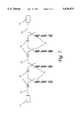
- FIG. 1schematically depicts a length of single mode fibre in which there is a series combination of two blazed Bragg gratings in tandem with a normally reflective Bragg grating;
- FIG. 2schematically depicts the spectral transmission characteristics of the series combination of the two blazed Bragg gratings of FIG. 1;
- FIG. 3schematically depicts the spectral reflection characteristics of the normally reflective grating of FIG. 1;
- FIGS. 4 and 5schematically depict the fibre of FIG. 1 optically coupled respectively with a three-pod optical circulator and with a four-port 3 dB tapered fused coupler;
- FIG. 6depicts a filter comprising a 3 dB tapered fused fibre coupler with the arrangement of three Bragg gratings as in FIG. 1 in both fibres on one side of its coupling region, and
- FIG. 7depicts an optical transmission system incorporating a plurality of the filters of FIG. 5.
- blazed gratings 3 and 4are photo-induced two blazed Bragg gratings 3 and 4, and a normally reflective grating 5.
- the periodicities of blazed gratings 3 and 4are such as to provide them with wavebands ⁇ 1 and ⁇ 2 (FIG. 2) over which they respectively couple light from the propagating mode guided by optical fibre 2 into radiating modes whose power is dissipated. Accordingly, for a single passage of light through the two blazed gratings 3 and 4, they provide a spectral transmission Characteristic as depicted by curve 20.
- Curve 39shows the corresponding spectral reflection characteristic for the normally reflective Bragg grating 5.
- This Bragg gratingon its own, functions in reflection as a spectrally selective band-pass reflector reflective over a waveband ⁇ 3 , but typically the construction of such filters is liable to produce a spectral characteristic with side-bands 30a and 30b.
- the construction of the Bragg grating 5is such that the spectral waveband ⁇ 3 over which it is selectively reflective at least compasses the waveband separating waveband ⁇ 1 from waveband ⁇ 2 , and may be, as depicted in FIG. 3, slightly larger than this.
- the wavebands ⁇ 1 and ⁇ 2 of Bragg gratings 3 and 4are preferably chosen to compass respectively the side-bands 30a and 30b. In this way, light launched into optical fibre 2 from the end nearest grating 3 the combination exhibits a spectral reflection characteristic in which the spectral discrimination of curve 30 provided by the spectral reflective characteristic of grating 5 is twice enhanced by the spectral discrimination of curve 20 provided by the spectral transmission characteristic of gratings 3 and 4.
- the end of the combination nearer grating 3is connected to a circulator 40 as depicted in FIG. 4, or to one port of a 4-port 3 dB optical coupler 50 as depicted in FIG. 5.
- This coupler 50may conveniently be constituted by a single mode tapered fused optical fibre type 3 dB coupler.
- the arrangement of FIG. 5provides an additional 6dB loss which can be avoided by a Mach Zehnder type arrangement as depicted in FIG. 6 in which identical grating elements 3, 4 and 5 are located in both fibres of a 3 dB tapered fused coupler 60.
- FIG. 7there is schematically depicted an optical transmission system having an optical receiver 70 optically coupled to an optical transmitter 71 by means of a transmission path 72 that includes a plurality of optical amplifiers 73 and associated filters 74 constructed in accordance with the teachings of the present invention, for instance a filter as described above with particular reference to FIG. 5.
Landscapes
- Physics & Mathematics (AREA)
- Optics & Photonics (AREA)
- General Physics & Mathematics (AREA)
- Engineering & Computer Science (AREA)
- Electromagnetism (AREA)
- Microelectronics & Electronic Packaging (AREA)
- Plasma & Fusion (AREA)
- Optical Communication System (AREA)
- Optical Integrated Circuits (AREA)
Abstract
Description
Claims (8)
Applications Claiming Priority (2)
| Application Number | Priority Date | Filing Date | Title |
|---|---|---|---|
| GB9423105AGB9423105D0 (en) | 1994-11-16 | 1994-11-16 | Optical wave grating filter |
| GB942365 | 1994-11-16 |
Publications (1)
| Publication Number | Publication Date |
|---|---|
| US5638473Atrue US5638473A (en) | 1997-06-10 |
Family
ID=10764482
Family Applications (1)
| Application Number | Title | Priority Date | Filing Date |
|---|---|---|---|
| US08/558,709Expired - Fee RelatedUS5638473A (en) | 1994-11-16 | 1995-11-16 | Optical waveguide grating filter |
Country Status (4)
| Country | Link |
|---|---|
| US (1) | US5638473A (en) |
| EP (1) | EP0713110B1 (en) |
| DE (1) | DE69525223T2 (en) |
| GB (1) | GB9423105D0 (en) |
Cited By (32)
| Publication number | Priority date | Publication date | Assignee | Title |
|---|---|---|---|---|
| US5740292A (en)* | 1996-09-12 | 1998-04-14 | Lucent Technologies Inc. | Mode coupling optical waveguide grating |
| US5778119A (en)* | 1996-10-08 | 1998-07-07 | Jds Fitel Inc. | In-line grating device for forward coupling light |
| US5812306A (en)* | 1996-06-14 | 1998-09-22 | Ciena Corporation | Bidirectional WDM optical communication systems with bidirectional optical amplifiers |
| US5844926A (en)* | 1995-06-21 | 1998-12-01 | Northern Telecom Limited | Lasers |
| US5915052A (en)* | 1997-06-30 | 1999-06-22 | Uniphase Telecommunications Products, Inc. | Loop status monitor for determining the amplitude of the signal components of a multi-wavelength optical beam |
| US5930437A (en)* | 1996-05-24 | 1999-07-27 | Fujikura Ltd. | Optical filter with planar optical waveguide having periodically varied distribution of refractive index and production process thereof |
| US5982964A (en)* | 1997-06-30 | 1999-11-09 | Uniphase Corporation | Process for fabrication and independent tuning of multiple integrated optical directional couplers on a single substrate |
| US6020986A (en)* | 1997-11-21 | 2000-02-01 | Jds Uniphase Corporation | Programmable add-drop module for use in an optical circuit |
| US6025915A (en)* | 1998-06-25 | 2000-02-15 | Litton Systems, Inc. | Scale factor stabilization of a broadband fiber source used in fiber optic gyroscopes in radiation environments |
| US6031849A (en)* | 1997-11-14 | 2000-02-29 | Jds Uniphase Corporation | High power three level fiber laser and method of making same |
| US6047096A (en)* | 1997-03-07 | 2000-04-04 | Telefonaktiebolaget Lm Ericsson | Optical device |
| WO2000029887A1 (en)* | 1998-11-17 | 2000-05-25 | Templex Technology, Inc. | Codes, methods, and apparatus for optical encoding and decoding |
| US6151157A (en)* | 1997-06-30 | 2000-11-21 | Uniphase Telecommunications Products, Inc. | Dynamic optical amplifier |
| US6226424B1 (en) | 1997-09-19 | 2001-05-01 | Uniphase Telecommunications Products, Inc. | Integrated wavelength-select transmitter |
| US6304380B1 (en)* | 2000-03-06 | 2001-10-16 | Lucent Technologies Inc. | Reducing polarization dependency of optical apparatus |
| US6313771B1 (en) | 1999-11-17 | 2001-11-06 | Templex Technology, Inc. | Codes, methods, and apparatus for optical encoding and decoding |
| US6480312B1 (en)* | 1997-12-16 | 2002-11-12 | Sumitomo Electric Industries, Ltd. | Dispersion compensating system used for bi-directional optical communication |
| US6493117B1 (en) | 1997-08-27 | 2002-12-10 | Nortel Networks Limited | WDM optical network with passive pass-through at each node |
| US20030098971A1 (en)* | 2000-09-29 | 2003-05-29 | Guillaume Laffont | Refractometer with blazed bragg gratings |
| KR100396266B1 (en)* | 2001-09-26 | 2003-09-02 | 삼성전자주식회사 | Gain flattening device of a fiber amplifier |
| US6724955B2 (en)* | 2000-05-16 | 2004-04-20 | Yutaka Sasaki | Add-drop multiplexer with signal amplification ability |
| US6751414B1 (en)* | 1997-07-18 | 2004-06-15 | Nortel Networks Limited | Circuit and channel assignment plan for optical transmissions |
| US20050036784A1 (en)* | 2002-08-12 | 2005-02-17 | Alcatel | Optical filter and transmission system incorporating an optical filter |
| US20060045422A1 (en)* | 2004-08-26 | 2006-03-02 | Provost Lionel A | Slanted Bragg Grating gain flattening filter having spatially overlapping elementary filters and a manufacturing method therefor |
| US20060067616A1 (en)* | 2002-08-22 | 2006-03-30 | Shishido Kanji | Pseudo slant fiber bragg grating, multiple series fiber bragg grating, optical fiber type coupler and optical connector |
| US20060091305A1 (en)* | 2004-11-03 | 2006-05-04 | Anders Grunnet-Jepsen | Optical phased array transmitter/receiver |
| US20060127004A1 (en)* | 2004-12-13 | 2006-06-15 | General Dynamics Advanced Information Systems, Inc. | System and method for performing dispersion compensation |
| US20080050078A1 (en)* | 2006-07-25 | 2008-02-28 | Digonnet Michel J | Apparatus and methods using hollow-core fiber tapers |
| US7386204B1 (en) | 2000-08-26 | 2008-06-10 | Cidra Corporation | Optical filter having a shaped filter function |
| US20090110344A1 (en)* | 2007-10-26 | 2009-04-30 | Little Brent E | Symmetric Optical Circuit with Integrated Polarization Rotator |
| US7792403B1 (en) | 2005-09-08 | 2010-09-07 | Infinera Corporation | Adiabatic polarization converter |
| US20100230621A1 (en)* | 2009-03-10 | 2010-09-16 | Rideout Howard | Photonic filtering of electrical signals |
Families Citing this family (11)
| Publication number | Priority date | Publication date | Assignee | Title |
|---|---|---|---|---|
| JPH1032562A (en)* | 1996-07-16 | 1998-02-03 | Fujitsu Ltd | Optical add / drop circuit |
| US5717798A (en)* | 1996-09-12 | 1998-02-10 | Lucent Technologies Inc. | Optical waveguide system comprising a mode coupling grating and a mode discrimination coupler |
| KR0183945B1 (en)* | 1996-11-28 | 1999-05-15 | 삼성전자주식회사 | Optical demultiplexer |
| US6295149B1 (en) | 1997-01-15 | 2001-09-25 | Pirelli Cavi E Sistemi S.P.A. | System and method of telecommunication with wavelength division multiplexing comprising a demultiplexer |
| AUPO511697A0 (en)* | 1997-02-14 | 1997-04-11 | Aofr Pty Limited | An optical waveguide guide |
| GB9815400D0 (en)* | 1997-08-12 | 1998-09-16 | Univ Southampton | Optical wavelength division multiplexer |
| JPH11119054A (en)* | 1997-10-16 | 1999-04-30 | Fujitsu Ltd | Optical multiplexer / demultiplexer |
| EP1108235A4 (en)* | 1998-06-04 | 2005-11-09 | California Inst Of Techn | OPTICAL COMPONENTS BASED ON ENERGY TRANSFER BETWEEN VARIOUS MODES IN OPTICAL WAVEGUIDE |
| US6275627B1 (en)* | 1998-09-25 | 2001-08-14 | Corning Incorporated | Optical fiber having an expanded mode field diameter and method of expanding the mode field diameter of an optical fiber |
| JP2001174653A (en)* | 1999-12-21 | 2001-06-29 | Nec Corp | Array waveguide grating |
| US6453102B1 (en) | 2000-02-07 | 2002-09-17 | Corning Incorporated | Dispersion compensating module and mode converter, coupler and dispersion compensating optical waveguide therein |
Citations (5)
| Publication number | Priority date | Publication date | Assignee | Title |
|---|---|---|---|---|
| US4807950A (en)* | 1984-08-13 | 1989-02-28 | United Technologies Corporation | Method for impressing gratings within fiber optics |
| US4911516A (en)* | 1989-02-27 | 1990-03-27 | General Electric Company | Optical device with mode selecting grating |
| US5042897A (en)* | 1989-12-26 | 1991-08-27 | United Technologies Corporation | Optical waveguide embedded light redirecting Bragg grating arrangement |
| US5210807A (en)* | 1992-06-29 | 1993-05-11 | The United States Of America As Represented By The Secretary Of The Navy | Variable wide band fiber optic delay line |
| US5384884A (en)* | 1990-11-08 | 1995-01-24 | British Telecommunications Public Limited Company | Method of forming optical fibre gratings |
Family Cites Families (7)
| Publication number | Priority date | Publication date | Assignee | Title |
|---|---|---|---|---|
| US5166940A (en)* | 1991-06-04 | 1992-11-24 | The Charles Stark Draper Laboratory, Inc. | Fiber laser and method of making same |
| GB2265059B (en)* | 1992-03-04 | 1995-07-26 | Northern Telecom Ltd | Optical regenerators |
| US5583689A (en)* | 1992-06-01 | 1996-12-10 | British Telecommunications Public Limited Company | Filter with preselected attenuation/wavelength characteristic |
| US5283686A (en) | 1992-07-27 | 1994-02-01 | General Instrument Corporation, Jerrold Communications | Optical systems with grating reflector |
| SE470454B (en)* | 1992-08-26 | 1994-04-11 | Ericsson Telefon Ab L M | Optical filter device |
| GB2275347A (en)* | 1993-02-19 | 1994-08-24 | Univ Southampton | Optical waveguide grating formed by transverse optical exposure |
| GB2283831B (en) | 1993-11-10 | 1996-11-06 | Northern Telecom Ltd | Optical fibre elements |
- 1994
- 1994-11-16GBGB9423105Apatent/GB9423105D0/enactivePending
- 1995
- 1995-11-16DEDE69525223Tpatent/DE69525223T2/ennot_activeExpired - Fee Related
- 1995-11-16EPEP95308201Apatent/EP0713110B1/ennot_activeExpired - Lifetime
- 1995-11-16USUS08/558,709patent/US5638473A/ennot_activeExpired - Fee Related
Patent Citations (5)
| Publication number | Priority date | Publication date | Assignee | Title |
|---|---|---|---|---|
| US4807950A (en)* | 1984-08-13 | 1989-02-28 | United Technologies Corporation | Method for impressing gratings within fiber optics |
| US4911516A (en)* | 1989-02-27 | 1990-03-27 | General Electric Company | Optical device with mode selecting grating |
| US5042897A (en)* | 1989-12-26 | 1991-08-27 | United Technologies Corporation | Optical waveguide embedded light redirecting Bragg grating arrangement |
| US5384884A (en)* | 1990-11-08 | 1995-01-24 | British Telecommunications Public Limited Company | Method of forming optical fibre gratings |
| US5210807A (en)* | 1992-06-29 | 1993-05-11 | The United States Of America As Represented By The Secretary Of The Navy | Variable wide band fiber optic delay line |
Cited By (55)
| Publication number | Priority date | Publication date | Assignee | Title |
|---|---|---|---|---|
| US5844926A (en)* | 1995-06-21 | 1998-12-01 | Northern Telecom Limited | Lasers |
| US5930437A (en)* | 1996-05-24 | 1999-07-27 | Fujikura Ltd. | Optical filter with planar optical waveguide having periodically varied distribution of refractive index and production process thereof |
| US5812306A (en)* | 1996-06-14 | 1998-09-22 | Ciena Corporation | Bidirectional WDM optical communication systems with bidirectional optical amplifiers |
| US5740292A (en)* | 1996-09-12 | 1998-04-14 | Lucent Technologies Inc. | Mode coupling optical waveguide grating |
| US5778119A (en)* | 1996-10-08 | 1998-07-07 | Jds Fitel Inc. | In-line grating device for forward coupling light |
| US6047096A (en)* | 1997-03-07 | 2000-04-04 | Telefonaktiebolaget Lm Ericsson | Optical device |
| US6151157A (en)* | 1997-06-30 | 2000-11-21 | Uniphase Telecommunications Products, Inc. | Dynamic optical amplifier |
| US5982964A (en)* | 1997-06-30 | 1999-11-09 | Uniphase Corporation | Process for fabrication and independent tuning of multiple integrated optical directional couplers on a single substrate |
| US5915052A (en)* | 1997-06-30 | 1999-06-22 | Uniphase Telecommunications Products, Inc. | Loop status monitor for determining the amplitude of the signal components of a multi-wavelength optical beam |
| US6751414B1 (en)* | 1997-07-18 | 2004-06-15 | Nortel Networks Limited | Circuit and channel assignment plan for optical transmissions |
| US6751418B2 (en) | 1997-08-27 | 2004-06-15 | Nortel Networks Limited | WDM optical network with passive pass-through at each node |
| US6757498B2 (en) | 1997-08-27 | 2004-06-29 | Nortel Networks Limited | WDM optical network with passive pass-through at each node |
| US6631018B1 (en) | 1997-08-27 | 2003-10-07 | Nortel Networks Limited | WDM optical network with passive pass-through at each node |
| US6775479B2 (en) | 1997-08-27 | 2004-08-10 | Nortel Networks Corporation | WDM optical network with passive pass-through at each node |
| US6795652B2 (en) | 1997-08-27 | 2004-09-21 | Nortel Networks Limited | WDM optical network with passive pass-through at each node |
| US6892032B2 (en) | 1997-08-27 | 2005-05-10 | Nortel Networks Limited | WDM optical network with passive pass-through at each node |
| US6748174B2 (en) | 1997-08-27 | 2004-06-08 | Nortel Networks Limited | WDM optical network with passive pass-through at each node |
| US20030215238A1 (en)* | 1997-08-27 | 2003-11-20 | Nortel Networks Limited | WDM optical network with passive pass-through at each node |
| US6493117B1 (en) | 1997-08-27 | 2002-12-10 | Nortel Networks Limited | WDM optical network with passive pass-through at each node |
| US6529300B1 (en) | 1997-08-27 | 2003-03-04 | Nortel Networks Limited | WDM optical network with passive pass-through at each node |
| US6556321B1 (en) | 1997-08-27 | 2003-04-29 | Nortel Networks Limited | WDM optical network and switching node with pilot tone communications |
| US6563615B2 (en) | 1997-08-27 | 2003-05-13 | Nortel Networks Limited | Technique for detecting noise on a data channel |
| US6226424B1 (en) | 1997-09-19 | 2001-05-01 | Uniphase Telecommunications Products, Inc. | Integrated wavelength-select transmitter |
| US6370290B1 (en) | 1997-09-19 | 2002-04-09 | Uniphase Corporation | Integrated wavelength-select transmitter |
| US6031849A (en)* | 1997-11-14 | 2000-02-29 | Jds Uniphase Corporation | High power three level fiber laser and method of making same |
| US6020986A (en)* | 1997-11-21 | 2000-02-01 | Jds Uniphase Corporation | Programmable add-drop module for use in an optical circuit |
| US6480312B1 (en)* | 1997-12-16 | 2002-11-12 | Sumitomo Electric Industries, Ltd. | Dispersion compensating system used for bi-directional optical communication |
| US6025915A (en)* | 1998-06-25 | 2000-02-15 | Litton Systems, Inc. | Scale factor stabilization of a broadband fiber source used in fiber optic gyroscopes in radiation environments |
| WO2000029887A1 (en)* | 1998-11-17 | 2000-05-25 | Templex Technology, Inc. | Codes, methods, and apparatus for optical encoding and decoding |
| US6313771B1 (en) | 1999-11-17 | 2001-11-06 | Templex Technology, Inc. | Codes, methods, and apparatus for optical encoding and decoding |
| US6304380B1 (en)* | 2000-03-06 | 2001-10-16 | Lucent Technologies Inc. | Reducing polarization dependency of optical apparatus |
| US6724955B2 (en)* | 2000-05-16 | 2004-04-20 | Yutaka Sasaki | Add-drop multiplexer with signal amplification ability |
| US7386204B1 (en) | 2000-08-26 | 2008-06-10 | Cidra Corporation | Optical filter having a shaped filter function |
| US20030098971A1 (en)* | 2000-09-29 | 2003-05-29 | Guillaume Laffont | Refractometer with blazed bragg gratings |
| US7184135B2 (en)* | 2000-09-29 | 2007-02-27 | Commissariat A L'energie Atomique | Refractometer with blazed bragg gratings |
| KR100396266B1 (en)* | 2001-09-26 | 2003-09-02 | 삼성전자주식회사 | Gain flattening device of a fiber amplifier |
| US20050036784A1 (en)* | 2002-08-12 | 2005-02-17 | Alcatel | Optical filter and transmission system incorporating an optical filter |
| US7302194B2 (en)* | 2002-08-12 | 2007-11-27 | Alcatel | Optical filter and transmission system incorporating an optical filter |
| US20060067616A1 (en)* | 2002-08-22 | 2006-03-30 | Shishido Kanji | Pseudo slant fiber bragg grating, multiple series fiber bragg grating, optical fiber type coupler and optical connector |
| US20060045422A1 (en)* | 2004-08-26 | 2006-03-02 | Provost Lionel A | Slanted Bragg Grating gain flattening filter having spatially overlapping elementary filters and a manufacturing method therefor |
| US7376306B2 (en)* | 2004-08-26 | 2008-05-20 | Avanex Corporation | Slanted Bragg grating gain flattening filter having spatially overlapping elementary filters and a manufacturing method therefor |
| US7095925B2 (en)* | 2004-11-03 | 2006-08-22 | Intel Corporation | Optical phased array transmitter/receiver |
| US20060091305A1 (en)* | 2004-11-03 | 2006-05-04 | Anders Grunnet-Jepsen | Optical phased array transmitter/receiver |
| US7295738B2 (en) | 2004-12-13 | 2007-11-13 | General Dynamics Advanced Information Systems, Inc. | System and method for performing dispersion compensation |
| US20060127004A1 (en)* | 2004-12-13 | 2006-06-15 | General Dynamics Advanced Information Systems, Inc. | System and method for performing dispersion compensation |
| US7792403B1 (en) | 2005-09-08 | 2010-09-07 | Infinera Corporation | Adiabatic polarization converter |
| US7742665B2 (en)* | 2006-07-25 | 2010-06-22 | The Board Of Trustees Of The Leland Stanford Junior University | Apparatus and methods using hollow-core fiber tapers |
| US20080050078A1 (en)* | 2006-07-25 | 2008-02-28 | Digonnet Michel J | Apparatus and methods using hollow-core fiber tapers |
| US20100296093A1 (en)* | 2006-07-25 | 2010-11-25 | Digonnet Michel J F | Apparatus and methods using hollow-core fiber tapers |
| US8009948B2 (en) | 2006-07-25 | 2011-08-30 | The Board Of Trustees Of The Leland Stanford Junior University | Apparatus and methods using hollow-core fiber tapers |
| US8244086B2 (en) | 2006-07-25 | 2012-08-14 | The Board Of Trustees Of The Leland Stanford Junior University | Apparatus and methods using hollow-core fiber tapers |
| US7565041B2 (en) | 2007-10-26 | 2009-07-21 | Infinera Corporation | Symmetric optical circuit with integrated polarization rotator |
| US20090110344A1 (en)* | 2007-10-26 | 2009-04-30 | Little Brent E | Symmetric Optical Circuit with Integrated Polarization Rotator |
| US20100230621A1 (en)* | 2009-03-10 | 2010-09-16 | Rideout Howard | Photonic filtering of electrical signals |
| US8768121B2 (en) | 2009-03-10 | 2014-07-01 | Her Majesty The Queen In Right Of Canada, As Represented By The Minister Of Industry, Through The Communications Research Centre Canada | Photonic filtering of electrical signals |
Also Published As
| Publication number | Publication date |
|---|---|
| DE69525223T2 (en) | 2002-10-31 |
| EP0713110B1 (en) | 2002-01-30 |
| GB9423105D0 (en) | 1995-01-04 |
| EP0713110A1 (en) | 1996-05-22 |
| DE69525223D1 (en) | 2002-03-14 |
Similar Documents
| Publication | Publication Date | Title |
|---|---|---|
| US5638473A (en) | Optical waveguide grating filter | |
| US5283686A (en) | Optical systems with grating reflector | |
| EP0706270B1 (en) | Optical amplifiers for wavelength division multiplexed systems | |
| US5825520A (en) | Optical demultiplexers with grating reflectors | |
| US6185023B1 (en) | Optical add-drop multiplexers compatible with very dense WDM optical communication systems | |
| US5748350A (en) | Dense wavelength division multiplexer and demultiplexer devices | |
| US5311606A (en) | Optical filter and optical amplifier employing said optical filters | |
| KR100207602B1 (en) | Optical filter for preventing loss of optical power and optical demultiplexer using same | |
| US6744943B2 (en) | Add-drop filter utilizing chiral elements | |
| JP3448182B2 (en) | All-optical fiber optical router | |
| CA2203729C (en) | Method and circuit for demultiplexing an optical signal | |
| JP2977024B2 (en) | Optical circuit for wavelength division multiplexing communication and optical transmission communication system including the same | |
| CA2220319C (en) | Hybrid bi-directional wavelength division multiplexing device | |
| US5751456A (en) | Multiwavelength add/drop multiplexer | |
| US6201907B1 (en) | Optical drop circuit having group delay compensation | |
| EP0493132B1 (en) | Waveguide-type coupler/splitter | |
| US20020067526A1 (en) | Bi-directional optical add/drop multiplexer | |
| GB2295247A (en) | Optical waveguide grating filter having two or three gratings | |
| KR0183945B1 (en) | Optical demultiplexer | |
| KR20020012189A (en) | A device and method for filtering optical wavelengths | |
| US6124959A (en) | Optical wavelength-division multiplexing transmission system | |
| US6337933B1 (en) | Narrow bandwidth fiber bragg grating apparatus | |
| US6549701B1 (en) | Selectable wavelength channel filter for optical WDM systems | |
| US6546167B1 (en) | Tunable grating optical device | |
| JPS5815926Y2 (en) | Composite optical wavelength demultiplexing circuit |
Legal Events
| Date | Code | Title | Description |
|---|---|---|---|
| AS | Assignment | Owner name:NORTHERN TELECOM LIMITED, CANADA Free format text:ASSIGNMENT OF ASSIGNORS INTEREST;ASSIGNOR:BYRON, KEVIN CHRISTOPHER;REEL/FRAME:007935/0339 Effective date:19951122 | |
| AS | Assignment | Owner name:NORTEL NETWORKS CORPORATION, CANADA Free format text:CHANGE OF NAME;ASSIGNOR:NORTHERN TELECOM LIMITED;REEL/FRAME:010567/0001 Effective date:19990429 | |
| AS | Assignment | Owner name:NORTEL NETWORKS LIMITED, CANADA Free format text:CHANGE OF NAME;ASSIGNOR:NORTEL NETWORKS CORPORATION;REEL/FRAME:011195/0706 Effective date:20000830 Owner name:NORTEL NETWORKS LIMITED,CANADA Free format text:CHANGE OF NAME;ASSIGNOR:NORTEL NETWORKS CORPORATION;REEL/FRAME:011195/0706 Effective date:20000830 | |
| FPAY | Fee payment | Year of fee payment:4 | |
| AS | Assignment | Owner name:BOOKHAM TECHNOLOGY PLC, UNITED KINGDOM Free format text:ASSIGNMENT OF ASSIGNORS INTEREST;ASSIGNOR:NORTEL NETWORKS CORPORATION;REEL/FRAME:013678/0050 Effective date:20021218 | |
| AS | Assignment | Owner name:NORTEL NETWORKS CORPORATION, ONTARIO Free format text:SECURITY INTEREST;ASSIGNORS:BOOKHAM TECHNOLOGY PLC;BOOKHAM TECHNOLOGY, INC.;BOOKHAM ACQUISITION, INC.;AND OTHERS;REEL/FRAME:013691/0552 Effective date:20021108 | |
| REMI | Maintenance fee reminder mailed | ||
| AS | Assignment | Owner name:NORTEL NETWORKS UK LIMITED, ENGLAND Free format text:ASSIGNMENT OF ASSIGNORS INTEREST;ASSIGNOR:BOOKHAM, INC.;REEL/FRAME:016309/0469 Effective date:20041202 | |
| LAPS | Lapse for failure to pay maintenance fees | ||
| LAPS | Lapse for failure to pay maintenance fees | Free format text:PATENT EXPIRED FOR FAILURE TO PAY MAINTENANCE FEES (ORIGINAL EVENT CODE: EXP.); ENTITY STATUS OF PATENT OWNER: LARGE ENTITY | |
| STCH | Information on status: patent discontinuation | Free format text:PATENT EXPIRED DUE TO NONPAYMENT OF MAINTENANCE FEES UNDER 37 CFR 1.362 | |
| FP | Lapsed due to failure to pay maintenance fee | Effective date:20050610 | |
| AS | Assignment | Owner name:BOOKHAM (US), INC., CALIFORNIA Free format text:PATENT SECURITY AGREEMENT TERMINATION UNDER REEL 016309 FRAME 0469;ASSIGNOR:NORTEL NETWORKS UK LIMITED;REEL/FRAME:017097/0822 Effective date:20060116 Owner name:BOOKHAM (SWITZERLAND) AG, SWITZERLAND Free format text:PATENT SECURITY AGREEMENT TERMINATION UNDER REEL 016309 FRAME 0469;ASSIGNOR:NORTEL NETWORKS UK LIMITED;REEL/FRAME:017097/0822 Effective date:20060116 Owner name:BOOKHAM TECHNOLOGY, INC., MARYLAND Free format text:PATENT SECURITY AGREEMENT TERMINATION UNDER REEL 013691 FRAME 0552;ASSIGNOR:NORTEL NETWORKS CORPORATION;REEL/FRAME:017097/0770 Effective date:20060118 Owner name:BOOKHAM TECHNOLOGY PLC, UNITED KINGDOM Free format text:PATENT SECURITY AGREEMENT TERMINATION UNDER REEL 013691 FRAME 0552;ASSIGNOR:NORTEL NETWORKS CORPORATION;REEL/FRAME:017097/0770 Effective date:20060118 Owner name:BOOKHAM (SWITZERLAND) AG, SWITZERLAND Free format text:PATENT SECURITY AGREEMENT TERMINATION UNDER REEL 013691 FRAME 0552;ASSIGNOR:NORTEL NETWORKS CORPORATION;REEL/FRAME:017097/0770 Effective date:20060118 Owner name:BOOKHAM ACQUISITION, INC., UNITED KINGDOM Free format text:PATENT SECURITY AGREEMENT TERMINATION UNDER REEL 013691 FRAME 0552;ASSIGNOR:NORTEL NETWORKS CORPORATION;REEL/FRAME:017097/0770 Effective date:20060118 Owner name:BOOKHAM, INC., CALIFORNIA Free format text:PATENT SECURITY AGREEMENT TERMINATION UNDER REEL 016309 FRAME 0469;ASSIGNOR:NORTEL NETWORKS UK LIMITED;REEL/FRAME:017097/0822 Effective date:20060116 Owner name:BOOKHAM TECHNOLOGY PLC, UNITED KINGDOM Free format text:PATENT SECURITY AGREEMENT TERMINATION UNDER REEL 016309 FRAME 0469;ASSIGNOR:NORTEL NETWORKS UK LIMITED;REEL/FRAME:017097/0822 Effective date:20060116 Owner name:BOOKHAM (CANADA) INC., CANADA Free format text:PATENT SECURITY AGREEMENT TERMINATION UNDER REEL 016309 FRAME 0469;ASSIGNOR:NORTEL NETWORKS UK LIMITED;REEL/FRAME:017097/0822 Effective date:20060116 |