US5638003A - Method and apparatus for testing surface breakdown of dielectric materials caused by electrical tracking - Google Patents
Method and apparatus for testing surface breakdown of dielectric materials caused by electrical trackingDownload PDFInfo
- Publication number
- US5638003A US5638003AUS08/447,644US44764495AUS5638003AUS 5638003 AUS5638003 AUS 5638003AUS 44764495 AUS44764495 AUS 44764495AUS 5638003 AUS5638003 AUS 5638003A
- Authority
- US
- United States
- Prior art keywords
- electrodes
- water
- dielectric
- electrolyte
- sample
- Prior art date
- Legal status (The legal status is an assumption and is not a legal conclusion. Google has not performed a legal analysis and makes no representation as to the accuracy of the status listed.)
- Expired - Lifetime
Links
Images


Classifications
- G—PHYSICS
- G01—MEASURING; TESTING
- G01R—MEASURING ELECTRIC VARIABLES; MEASURING MAGNETIC VARIABLES
- G01R31/00—Arrangements for testing electric properties; Arrangements for locating electric faults; Arrangements for electrical testing characterised by what is being tested not provided for elsewhere
- G01R31/12—Testing dielectric strength or breakdown voltage ; Testing or monitoring effectiveness or level of insulation, e.g. of a cable or of an apparatus, for example using partial discharge measurements; Electrostatic testing
- G01R31/1227—Testing dielectric strength or breakdown voltage ; Testing or monitoring effectiveness or level of insulation, e.g. of a cable or of an apparatus, for example using partial discharge measurements; Electrostatic testing of components, parts or materials
- G01R31/1263—Testing dielectric strength or breakdown voltage ; Testing or monitoring effectiveness or level of insulation, e.g. of a cable or of an apparatus, for example using partial discharge measurements; Electrostatic testing of components, parts or materials of solid or fluid materials, e.g. insulation films, bulk material; of semiconductors or LV electronic components or parts; of cable, line or wire insulation
Definitions
- the present inventionrelates generally to the testing of dielectric materials, and more particularly to a novel method and apparatus for surface testing dielectric materials for surface breakdown caused by electrical tracking in the presence of contaminants.
- the conditions which may lead to arcing of an insulator in the presence of contaminantsis often controlled by a number of factors. Chief among the factors is the voltage applied across the insulator and the electrical rating of the insulator itself. Rain striking the insulator forms a thin conductive film across the surface of the insulator. Where the surface of the insulator is impervious to the penetration of water (e.g., fired ceramic) the film may remain thin and the potential for arcing small. Where the insulator is porous (e.g., unfired ceramic) the film of water and contaminants effectively becomes thicker due to penetration of the water and contaminants into the insulator.
- the heat of the arcmay drive away the water leaving only the undissolved contaminants of the air pollution deposited on the insulator as a solid coating material. Subsequent raindrops striking a fired ceramic insulator may dilute and wash away the deposited air pollution.
- the insulatoris fabricated of a porous ceramic, the contaminants are often deposited within the porous matrix of the ceramic and cannot be washed away. Subsequent deposits and arcing causes an accumulation of contaminants within and near the surface of the insulator and progressively more severe arcing. Where the contaminant is an organic material the heat of the arc will often result in the contaminant being reduced to a conductive carbonaceous material.
- trackingthe localized presence of carbon on or near the surface of the insulator will often be the source of subsequent arcs and eventually a path of carbon will develop providing a track for subsequent arcing.
- the accumulation of the carbon into a continuous pathis commonly referred to as tracking.
- the insulatoris also fabricated of an organic material (e.g., plastic)
- trackingcan occur at a much faster rate due to thermal breakdown of the organic material.
- the contaminants and also the plastic along the path of the arcmay be converted into carbon by the heat of the arc.
- porosity of the insulatoris an important factor in tracking, even non-electrolytes (e.g., solvents or airborne dust) may exacerbate tracking by accumulating and penetrating the insulator to provide a source of an initial and subsequent arcs.
- CTI testa comparative tracking index test described as a comparative tracking index test.
- CTI testa pair of standardized electrodes are disposed on a surface of a test sample of the dielectric material of an insulator and an electrolyte is deposited on the dielectric between the electrodes by a slow dripping process.
- Failure of a dielectric specimen under the CTI testis defined by a current of at least 0.5 ampere for two seconds before at least 50 droplets have fallen onto the sample.
- the comparative measurement of failureis referred to as the "comparative tracking index number", or simply "CTI", and is the magnitude of the highest voltage reached before failure.
- IEC, ASTM, BSI, etc. test Publicationsspecify a number of test parameters.
- the electrodesare to be mutually separated by a distance of 4.0 (+0.1, -0.1) mm during testing.
- the droplets striking the test sampleare to be of a diameter of 20 (+3, -0) mm 3 and are to be released from a specified height above the test sample.
- the test proceduresrecommend cleaning the electrodes before each use.
- the electrodesmust have a specified weight such that the electrodes exert a constant force against the surface of the specimen.
- Saito et al.in U.S. Pat. No. 4,339,708 (Saito).
- Saitorecognized that some of the variables associated with testing may result from contamination of the droplet nozzle, and went on to introduce other variables by allowing movement of the droplet nozzle before and during release of the droplets. Such movement, while intending to reduce variability of the IEC test, may actually have increased variability.
- the CTI testis of considerable importance not only to power companies but also to manufacturers of any power consuming device subject to environmental factors. Because of the importance of CTI testing a more reproducible method is needed for implementing the test of IEC Publication 112.
- One of the primary objects of the present inventionis to improve the reliability of dielectric surface testing by surrounding a testing fixture with an air-tight enclosure and purging the enclosure of smoke or other air-borne contaminants at a predetermined rate during testing.
- a further objective of the present inventionis to improve the reliability of dielectric surface testing by providing a set of vertically floating test electrodes which provide a constant-force contact with the dielectric surface during testing.
- the apparatusincludes an enclosure continuously purged of air-borne contaminants and a base disposed within the enclosure for supporting the dielectric sample.
- a pair of electrodesare operably interconnected with a variable voltage power supply and engage the dielectric test sample on a first side with a mutual separation.
- a source of water and water borne contaminantsintermittently discharges the water and water-borne contaminants in droplet form onto the dielectric test sample between the electrodes.
- burn-throughmay effect the validity of CTI testing results, where the testing electrodes burn through a test specimen of dielectric material preventing surface tracking at the 4 mm distance between the electrode tips.
- a pair of sensorsare located under the test sample and trigger an alarm upon burn-through thereby eliminating the uncertainties associated with such a condition.
- floodingis a significant factor in testing variability where an envelope voltage is set too low to evaporate accumulated droplets.
- the accumulation of dropletsresults in overflow of the test area and shorting of the electrodes, preventing establishment of a valid CTI value.
- the present inventiondetects such condition by locating sensors around the periphery of the support base under the test sample, terminating the test and sounding an alarm upon detection of such a condition.
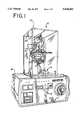
- FIG. 1is a perspective view of a test system in accordance with a preferred embodiment of the present invention
- FIG. 2is a perspective view of the test head of the test system of FIG. 1, but with portions of the transparent enclosure broken away for clarity;
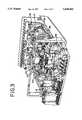
- FIG. 3is a rearward end perspective view of a partially disassembled control enclosure of the test system of FIG. 1;
- FIG. 4is a schematic control circuit of the test system of FIG. 1;
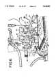
- FIG. 5is a perspective view of the partially disassembled control enclosure of the test system of FIG. 1 but taken from its forward end.
- FIG. 6is a perspective view of the base of the system of FIG. 1 with the cover removed.
- FIG. 1is a perspective view of a test apparatus in accordance with the present invention, indicated generally at 10, for carrying out testing under IEC Publication 112, ASTM D3638, DIN 53480, BSI 5901, VDE 0303 TEiL, AFNORC 26220.
- the test apparatus 10which may alternatively be referred to as a test system, includes a rectangular enclosure 12 which surrounds a test head 14 and associated fixturing, and a control enclosure 16.
- the enclosure 12is generally constructed of 3/8 inch thick transparent Lexan® panels generally forming an air-tight enclosure. Glue and screws may be used to join the panels at mutually engaging marginal edges and gaskets may be used as necessary to maintain the integrity of a controlled atmosphere within the enclosure 12.
- Openings 18, 20exist to flush smoke and other air-borne contaminants from the enclosure 12.
- the atmosphere within the enclosure 12is controlled by purging the enclosure 12 with compressed air which is introduced into the enclosure 12 through a first opening 18 (FIG. 2) at the bottom of the enclosure 12 and outwardly forced through an opening 20 (FIG. 6) located in the top of the pump support column, and an adjustable position exhaust tube 52 (FIG. 2) which is positioned above and slightly behind the dielectric test sample.
- a fan 142(FIG. 3) of sufficient air flow and pressure (e.g., Allied Electronics #599-0322)) is provided to maintain a constant air flow across the dielectric test sample at a linear velocity of 0.1 meter per second.
- Vinyl tubingis used to interconnect the fan 24 to the inlet of the enclosure 12.
- a vinyl tubing clamp 17is used to fine tune the air flow velocity over the sample.
- a flow indicator 19e.g., Humonics Inc., model 570 having a display range of 0.5 to 700 mL per minute through a 9 mm capillary tube has been determined to provide the desired 0.1 meter per second linear flow velocity at a displayed volumetric flow rate of 94.3 mL.
- the test head 14(FIG. 1) includes a base 22 of a transparent material as shown in FIG. 2 (preferably glass) for support of the dielectric test sample during testing and for holding the test sample in contact with a pair of electrodes 24. Consistent with the CTI tests, the electrodes 24 are separated during testing by a specified horizontal distance and exert a specified force. The vertical positioning of electrodes 24 is controlled by linear bearings 28. The horizontal separation of the tips of the electrodes 24 is controlled by a micropositioner and slide assembly 26. While one electrode assembly (i.e., the electrode assembly on the right in FIG. 1) remains in a fixed horizontal position, the electrode assembly on the left may be precisely positioned by adjusting the micropositioner assembly 26.
- a micropositioner and slide assembly 26While one electrode assembly (i.e., the electrode assembly on the right in FIG. 1) remains in a fixed horizontal position, the electrode assembly on the left may be precisely positioned by adjusting the micropositioner assembly 26.
- the micropositionermay be any appropriate positioning device (e.g., a micropositioner manufactured by Parker/Hannifin and sold by McMaster Carr of Chicago, Ill., under part number 5239A19).
- a micropositionermanufactured by Parker/Hannifin and sold by McMaster Carr of Chicago, Ill., under part number 5239A19.
- mutual separation of the electrodesmay be precisely established by placing a calibration device such as a feeler gauge or calibration block between the electrodes and adjusting the micropositioner 26 to an appropriate position in close proximity to the calibration device.
- the electrodes 24are fabricated of 5 mm ⁇ 2 mm rectangular platinum bars with a chisel point or rounded point with a specified radius, formed on the end of the bar along a long (5 mm) edge of the cross-section at a 30° angle to a longitudinal axis of the bar.
- the electrodes 24are clamped within a slot within a circular hub 25 by an electrode clamping screw 27.
- the hub 25is secured to a support arm 30 by a support arm clamping screw 31.
- the support arm clamping screw 31allows for horizontal adjustment of electrode position in a direction parallel to the support arm 30 and for rotation of the electrodes 24 such that the chisel edges of opposing electrodes 24 are in parallel alignment.
- the electrode clamping screws 27allows for axial adjustment of each electrode 24 such that the tip of each electrode extends a comparable distance from each hub 25.
- Electrodes 24Vertical positioning of the electrodes 24 is accomplished by a set of vertically oriented linear bearings 28 (e.g., Schneeberger model ND1-55.32 Micro Frictionless Tables) within which the electrode assemblies (i.e., electrodes 24 and supporting arms 30) are allowed to vertically float based upon the weight of each electrode assembly acting against the surface of the dielectric sample.
- the electrode assembliesare constructed to weigh 100 grams each and thereby, through the force of gravity, apply a force of 1N to the dielectric sample through each of the electrodes 24. As the electrodes become worn and resharpening becomes necessary, additional weight may be added to each electrode assembly by inserting small calibrated metal bars inside the hollow ends 32 of the support arms 30.
- an electrical isolation block 34(e.g., plexiglass) is interposed between the support arm 30 and linear bearing 28. Also, to further protect an operator against potential electrical shock during adjustment of the left electrode 24, the left electrode 24 is held at a ground potential while the right electrode 24 receives the full test voltage that may vary from 0 to 1000 volts. As further protection, door interlocks 126 are provided to disconnect power when the operator opens a door to adjust the electrode
- test head 14 and base 22may be independently leveled. Leveling enhances the reliability of testing in the case of the dielectric test sample on the base 22 by assuring that the droplets of contaminant remain where deposited instead of draining towards the lowest point of the dielectric sample.
- Leveling of the test head 14also enhances reliability of testing, in a first instance, by insuring that the contaminant drip tube remains centered over the electrodes and, in a second instance, by effecting a reliable electrode contact force through proper vertical alignment of the linear bearings guiding the test electrodes 24. Adjustment leveling of the test head 14 and base 22 is accomplished by adjustment of respective leveling screws 36.
- the drip tube 38may be fabricated of a metal known to be resistant to contaminant induced corrosion (e.g., 304 stainless steel).
- the discharge end of the drip tubemay be threaded to accept an appropriate droplet forming nozzle (e.g., a Fisher Scientific micro-valve part number 14-818-47B, Luer-Lock needle adapter supplied by Fisher Scientific under part number 14-818-48, and Luer-Lock needle from Fisher Scientific under part number SG-031576).
- an appropriate droplet forming nozzlee.g., a Fisher Scientific micro-valve part number 14-818-47B, Luer-Lock needle adapter supplied by Fisher Scientific under part number 14-818-48, and Luer-Lock needle from Fisher Scientific under part number SG-031576.
- the height or distance of the nozzle of the drip tube 38 above a dielectric test sample supported on the base 22is adjusted by a micropositioner 50.
- the micropositioner 50may comprise any precision positioning device (e.g., a Parker/Hanifin micropositioner sold by McMaster Carr of Chicago, Ill. under part number 5239A19).
- a sample pump 40 and droplet sensor 42are used to control the rate under which droplets are deposited on the dielectric test sample.
- the pump 40may comprise any variable volume (e.g., 0.01 to 0.04 ml per pulse) pumping device (e.g., Vicor Mfg. model number SV525A197-2 with 24-48 VDC coil) with provision to resist internal corrosion and contamination of the test liquid (e.g., all wetted parts are coated with VITON).
- the droplet sensor 42is used in conjunction with the pump 40 and a timer 124 (FIG. 4) to insure that a single droplet falls every 30 seconds.
- the timer 124starts the pump which then runs until the droplet sensor 42 detects a droplet falling from the droplet nozzle at which time the pump is deactivated.
- the droplet sensor 42may comprise a laser optical device operating in proximity to the droplet nozzle or a long range conventional optical device (e.g., an Omron model number E3C-J sensor).
- the pump timer 124(e.g., Omron model number H3CA-A24DC) is interconnected with a pump controller 126 (e.g., Omron model number H3CA-A24DC). Together, the pump timer 124 and controller 126 control the timing and volume of fluid contaminant delivered to the dielectric sample.
- a pump controller 126e.g., Omron model number H3CA-A24DC
- the droplet counter 122(e.g., Omron H7CN-XLNM 24 VDC with battery backup model number Y92S-20) counts the number of droplets delivered to the dielectric test sample during a test.
- a set-pointi.e., 50 drops
- the droplet counter 122disables the controls of the test system 10 and provides an indication of "Test Complete" upon timeout of a 25 second shutdown delay timer 123.
- the results of the test, the CTIis then read from the digital voltage display or a recorder as being the maximum continuous electrode voltage applied to the dielectric sample during the test.
- a sensor 44is provided to detect such flooding and take appropriate steps.
- the sensor 44(Flood Sensing Grid) is shown in FIG. 4 as being a parallel series of strips (positive and negative sensor leads) interconnected either to a "+" connection of a 24 VDC Supply or to an input (solid state relay (SSR)) of a flooding shutdown circuit 102 activated when a droplet of water bridges a positive and negative lead.
- the flood control circuit upon activationis shown to interrupt control power to the test system 10.
- the pump 40Upon activation of the test system 10, the pump 40 is provided with a pump purge feature activated by a PUMP PURGE button.
- the PUMP PURGE buttonallows the pump 40 and associated piping to be purged of air and to be filled with a proper mixture of fluid and contaminant (e.g., NH 4 CL).
- FIG. 4illustrates in circuit format a burn-through control circuit 104 causing shut-down of the test system 10 upon the occurrence of burn-through by interruption of control power through a latching relay of the burn-through control circuit 104.
- thermocouple 54is provided directly above the electrodes 24 as a means of detecting ignition and the presence of flames.
- a temperature limit switch 106(FIG. 4) (e.g., a Vulcan Electric Co. model number 891A16F) is used to deactivate the test system 10 when a detected temperature above the dielectric test sample exceeds safe threshold limits.
- the output contacts of the temperature limit switch 106may also be used to activate a flame extinguisher.
- Testing power for application to the dielectric test sample through electrodes 24originates from a variable transformer 112 (e.g., Ohmite Mfg. Co. model number VT10), a step-up transformer 108 (e.g., Magnetic and Controls Inc. 1 kVA, (1000 volt at 1 ampere), 120 volts input), and rheostat 110 (e.g., Ohmite Mfg. Co. model number 1000 ohm, 300 W).
- the variable transformer 112provides a voltage adjusting means through which a voltage applied to the dielectric may be controlled over a wide range.
- the step-up transformer 110provides an 1:8 step-up in voltage necessary to cover the maximum voltage specified in Publication 112.
- the rheostat 110functions to limit maximum current through the dielectric test sample to one ampere.
- the rheostat 110improves the quality of testing by reducing the magnitude of uncontrolled current and damage experienced during an arc.
- the magnitude of a limiting resistor(the rheostat 110) is automatically increased or decreased with an output voltage of the variable transformer 112.
- the ammeter 114may comprise a conventional current sensing device providing a true RMS reading (e.g., IMC Ottotek model number 708815) adapted to provide a recorder output signal upon sensing a preset current.
- the ammeter 114is, in turn, connected to an over-current timer relay 116.
- the over-current timer relay 116upon receiving an over-current signal from the ammeter 114, interrupts control power to the SSR 118, which in turn interrupts power to the variable transformer 112.
- the step-down transformer(e.g., Magnetics and Controls Inc., 1 kV input/500 V output) provides signal isolation between the main power supply 108, 110, 112 and the voltmeter 120 and also reduces the voltage applied to the voltmeter 120.
- the voltmeter 120may comprise any digital voltmeter providing a true RMS voltage reading (e.g., IMC Ottotek model 208533010 with 3.5 digit display) providing a low-voltage recorder output.
- an operatorbegins by placing a load calibrating device on the base 22 beneath the lower tips of the inclined electrodes. The operator then positions the tips of the electrodes onto the calibrating device, measures and, if necessary, calibrates the vertical force exerted by the electrodes 24 on the test sample. The operator measures the vertical force through use of the load cell 150 (e.g., Transducer Techniques model number GS-150 with a model number ALS04 load button) and load indicator 152 (e.g., Transducer Techniques model number DPM-2) as illustrated in FIG. 5. The load cell is placed under each of the electrodes 24 and the downward force supplied by each of the electrodes 24 noted. If the load varies outside of the limits specified in the applied standard, then calibrating weights may be either added or removed from the support arms 30 of the electrodes 24.
- the load cell 150e.g., Transducer Techniques model number GS-150 with a model number ALS04 load button
- load indicator 152e.g., Transducer Techniques model number DPM-2
- the operatorpurges the pump 40 and droplet nozzle 38 by activating a purge button 154. Fluid contaminant discharged from the droplet nozzle 38 during purging may be caught in a cup or other receptacle during purging.
- the operatorcalibrates the electrode spacing using the procedures described above. Following calibration of the electrode spacing the operator may raise the electrodes 24 and place a dielectric test sample under the electrodes 24. After installing the test sample the operator would close the enclosure 12 and press the "Test Start” button 158 and the "Drop Count Clear” button 156. The operator may also verify that the "Power” 164 indicator light is illuminated and that the other indicator lights “Test Complete” 168, "Sample Burn Through” 170, "Drop Detected” 172, "Pump Cycle” 166 “Overcurrent” 174, “Flood” 176, “Door Open” 178, and “Flame” 180 were off.
- the operatorthen sets an initial test voltage by adjusting the control knob 182 which is ganged with the rheostat 110 and variable transformer 112. The operator may then press the "High Voltage On” button. The operator may again visually scan the indicator lights for indication of normal operating conditions.
- the pump cycle timer 124would time out and activate the pump 40. After a suitable interval a droplet would form on the end of the droplet nozzle 38 and fall toward the test sample.
- the droplet detector 42would detect the fall of the droplet and reset the pump timer 124. The droplet detector would also increment the drop counter 122.
- the operatorwill move the electrodes 24 to a new location on the dielectric test sample and begin a new test at a lower voltage. If the test were terminated for sample burn-through or flame the operator would also move the electrodes to a new location and begin a new test.
- the droplet counter 122If, on the other hand, the droplet counter 122 has a drop total in excess of 50 drops, then the operator reads the voltage recorder for a CTI rating for that test. Initially the test voltage begins at 600 V and is reduced for each new test until 50 drops of the contaminant can be applied before failure.
- the test system 10provides a means for testing a dielectric sample for susceptibility to surface failure by tracking that is not taught by the prior art.
- the apparatus for purging the test chambereliminates the problems of smoke or other air-borne materials contaminating the droplet nozzle.
- the use of floating supports for the electrodes 24allows the electrodes to maintain contact with the dielectric material even under conditions of severe burning.
- the use of a rheostat ganged with a variable transformerreduces damage to dielectric and electrodes during arcs occurring at relatively high voltages while still allowing for higher relative currents at lower voltages.
- the flood sensing gridprovides a means of terminating testing where problems unrelated to arcing may ultimately invalidate the results of a test anyway.
Landscapes
- Physics & Mathematics (AREA)
- General Physics & Mathematics (AREA)
- Testing Relating To Insulation (AREA)
Abstract
Description
Claims (26)
Priority Applications (1)
| Application Number | Priority Date | Filing Date | Title |
|---|---|---|---|
| US08/447,644US5638003A (en) | 1995-05-23 | 1995-05-23 | Method and apparatus for testing surface breakdown of dielectric materials caused by electrical tracking |
Applications Claiming Priority (1)
| Application Number | Priority Date | Filing Date | Title |
|---|---|---|---|
| US08/447,644US5638003A (en) | 1995-05-23 | 1995-05-23 | Method and apparatus for testing surface breakdown of dielectric materials caused by electrical tracking |
Publications (1)
| Publication Number | Publication Date |
|---|---|
| US5638003Atrue US5638003A (en) | 1997-06-10 |
Family
ID=23777171
Family Applications (1)
| Application Number | Title | Priority Date | Filing Date |
|---|---|---|---|
| US08/447,644Expired - LifetimeUS5638003A (en) | 1995-05-23 | 1995-05-23 | Method and apparatus for testing surface breakdown of dielectric materials caused by electrical tracking |
Country Status (1)
| Country | Link |
|---|---|
| US (1) | US5638003A (en) |
Cited By (125)
| Publication number | Priority date | Publication date | Assignee | Title |
|---|---|---|---|---|
| US5841164A (en)* | 1995-10-30 | 1998-11-24 | Mitsubishi Denki Kabushiki Kaisha | Test structure for dielectric film evaluation |
| US6051111A (en)* | 1999-05-05 | 2000-04-18 | Prestidge; D. Joshua | Cold distillation method |
| DE19925802A1 (en)* | 1999-06-07 | 2000-12-14 | Deutsche Telekom Ag | Leakage current testing device in which the electrode mounting arrangement is improved to give a constant application force of the electrodes on the sample surface |
| US20070132474A1 (en)* | 2005-08-16 | 2007-06-14 | Professional Testing (Emi), Inc. | Automated platform for electronic apparatus environmental testing & method of use |
| US20070203485A1 (en)* | 2002-12-10 | 2007-08-30 | Keppel David S | Electrosurgical electrode having a non-conductive porous ceramic coating |
| US20070265616A1 (en)* | 2006-05-10 | 2007-11-15 | Sherwood Services Ag | Vessel sealing instrument with optimized power density |
| US20080004616A1 (en)* | 1997-09-09 | 2008-01-03 | Patrick Ryan T | Apparatus and method for sealing and cutting tissue |
| US20080082100A1 (en)* | 2006-10-03 | 2008-04-03 | Tyco Healthcare Group Lp | Radiofrequency fusion of cardiac tissue |
| US20080116918A1 (en)* | 2006-11-17 | 2008-05-22 | Suss Microtec Test Systems Gmbh | Probe station to testing semiconductor substrates and comprising emi shielding |
| US20080142726A1 (en)* | 2006-10-27 | 2008-06-19 | Keith Relleen | Multi-directional mechanical scanning in an ion implanter |
| US20080243120A1 (en)* | 2003-11-17 | 2008-10-02 | Kate Lawes | Bipolar forceps having monopolar extension |
| US20080249527A1 (en)* | 2007-04-04 | 2008-10-09 | Tyco Healthcare Group Lp | Electrosurgical instrument reducing current densities at an insulator conductor junction |
| US7435249B2 (en)* | 1997-11-12 | 2008-10-14 | Covidien Ag | Electrosurgical instruments which reduces collateral damage to adjacent tissue |
| US7442194B2 (en) | 2003-11-17 | 2008-10-28 | Covidien Ag | Bipolar forceps having monopolar extension |
| US7491201B2 (en) | 2003-05-15 | 2009-02-17 | Covidien Ag | Tissue sealer with non-conductive variable stop members and method of sealing tissue |
| US7491202B2 (en) | 2005-03-31 | 2009-02-17 | Covidien Ag | Electrosurgical forceps with slow closure sealing plates and method of sealing tissue |
| US7500975B2 (en) | 2003-11-19 | 2009-03-10 | Covidien Ag | Spring loaded reciprocating tissue cutting mechanism in a forceps-style electrosurgical instrument |
| US7510556B2 (en) | 1998-10-23 | 2009-03-31 | Coviden Ag | Vessel sealing instrument |
| US7513898B2 (en) | 1998-10-23 | 2009-04-07 | Covidien Ag | Vessel sealing instrument |
| US7540872B2 (en) | 2004-09-21 | 2009-06-02 | Covidien Ag | Articulating bipolar electrosurgical instrument |
| US7553312B2 (en) | 1998-10-23 | 2009-06-30 | Covidien Ag | Vessel sealing instrument |
| US7582087B2 (en) | 1998-10-23 | 2009-09-01 | Covidien Ag | Vessel sealing instrument |
| US7594916B2 (en) | 2005-11-22 | 2009-09-29 | Covidien Ag | Electrosurgical forceps with energy based tissue division |
| US7597693B2 (en) | 2003-06-13 | 2009-10-06 | Covidien Ag | Vessel sealer and divider for use with small trocars and cannulas |
| US7628791B2 (en) | 2005-08-19 | 2009-12-08 | Covidien Ag | Single action tissue sealer |
| US7641653B2 (en) | 2006-05-04 | 2010-01-05 | Covidien Ag | Open vessel sealing forceps disposable handswitch |
| US7655007B2 (en) | 2003-05-01 | 2010-02-02 | Covidien Ag | Method of fusing biomaterials with radiofrequency energy |
| US7686804B2 (en) | 2005-01-14 | 2010-03-30 | Covidien Ag | Vessel sealer and divider with rotating sealer and cutter |
| US7686827B2 (en) | 2004-10-21 | 2010-03-30 | Covidien Ag | Magnetic closure mechanism for hemostat |
| US7708735B2 (en) | 2003-05-01 | 2010-05-04 | Covidien Ag | Incorporating rapid cooling in tissue fusion heating processes |
| US7722607B2 (en) | 2005-09-30 | 2010-05-25 | Covidien Ag | In-line vessel sealer and divider |
| US7731717B2 (en) | 2006-08-08 | 2010-06-08 | Covidien Ag | System and method for controlling RF output during tissue sealing |
| US7744615B2 (en) | 2006-07-18 | 2010-06-29 | Covidien Ag | Apparatus and method for transecting tissue on a bipolar vessel sealing instrument |
| US7766910B2 (en) | 2006-01-24 | 2010-08-03 | Tyco Healthcare Group Lp | Vessel sealer and divider for large tissue structures |
| US7771425B2 (en) | 2003-06-13 | 2010-08-10 | Covidien Ag | Vessel sealer and divider having a variable jaw clamping mechanism |
| US7776036B2 (en) | 2003-03-13 | 2010-08-17 | Covidien Ag | Bipolar concentric electrode assembly for soft tissue fusion |
| US7776037B2 (en) | 2006-07-07 | 2010-08-17 | Covidien Ag | System and method for controlling electrode gap during tissue sealing |
| US7789878B2 (en) | 2005-09-30 | 2010-09-07 | Covidien Ag | In-line vessel sealer and divider |
| US7811283B2 (en) | 2003-11-19 | 2010-10-12 | Covidien Ag | Open vessel sealing instrument with hourglass cutting mechanism and over-ratchet safety |
| US7819872B2 (en) | 2005-09-30 | 2010-10-26 | Covidien Ag | Flexible endoscopic catheter with ligasure |
| US7828798B2 (en) | 1997-11-14 | 2010-11-09 | Covidien Ag | Laparoscopic bipolar electrosurgical instrument |
| US7837685B2 (en) | 2005-07-13 | 2010-11-23 | Covidien Ag | Switch mechanisms for safe activation of energy on an electrosurgical instrument |
| US7846161B2 (en) | 2005-09-30 | 2010-12-07 | Covidien Ag | Insulating boot for electrosurgical forceps |
| US7846158B2 (en) | 2006-05-05 | 2010-12-07 | Covidien Ag | Apparatus and method for electrode thermosurgery |
| US7857812B2 (en) | 2003-06-13 | 2010-12-28 | Covidien Ag | Vessel sealer and divider having elongated knife stroke and safety for cutting mechanism |
| US7879035B2 (en) | 2005-09-30 | 2011-02-01 | Covidien Ag | Insulating boot for electrosurgical forceps |
| US7877853B2 (en) | 2007-09-20 | 2011-02-01 | Tyco Healthcare Group Lp | Method of manufacturing end effector assembly for sealing tissue |
| US7877852B2 (en) | 2007-09-20 | 2011-02-01 | Tyco Healthcare Group Lp | Method of manufacturing an end effector assembly for sealing tissue |
| WO2011015420A1 (en)* | 2009-08-06 | 2011-02-10 | Robert Bosch Gmbh | Protection device for an inspection installation |
| US7887535B2 (en) | 1999-10-18 | 2011-02-15 | Covidien Ag | Vessel sealing wave jaw |
| US20110036183A1 (en)* | 2007-04-26 | 2011-02-17 | Tyco Healthcare Group, Lp | Apparatus and method for measuring pressure between jaw members |
| US7909823B2 (en) | 2005-01-14 | 2011-03-22 | Covidien Ag | Open vessel sealing instrument |
| US7922953B2 (en) | 2005-09-30 | 2011-04-12 | Covidien Ag | Method for manufacturing an end effector assembly |
| US7922718B2 (en) | 2003-11-19 | 2011-04-12 | Covidien Ag | Open vessel sealing instrument with cutting mechanism |
| US7931649B2 (en) | 2002-10-04 | 2011-04-26 | Tyco Healthcare Group Lp | Vessel sealing instrument with electrical cutting mechanism |
| US7935052B2 (en) | 2004-09-09 | 2011-05-03 | Covidien Ag | Forceps with spring loaded end effector assembly |
| US7951149B2 (en) | 2006-10-17 | 2011-05-31 | Tyco Healthcare Group Lp | Ablative material for use with tissue treatment device |
| US7955332B2 (en) | 2004-10-08 | 2011-06-07 | Covidien Ag | Mechanism for dividing tissue in a hemostat-style instrument |
| US7963965B2 (en) | 1997-11-12 | 2011-06-21 | Covidien Ag | Bipolar electrosurgical instrument for sealing vessels |
| US8016827B2 (en) | 2008-10-09 | 2011-09-13 | Tyco Healthcare Group Lp | Apparatus, system, and method for performing an electrosurgical procedure |
| USD649249S1 (en) | 2007-02-15 | 2011-11-22 | Tyco Healthcare Group Lp | End effectors of an elongated dissecting and dividing instrument |
| US8128624B2 (en) | 2003-05-01 | 2012-03-06 | Covidien Ag | Electrosurgical instrument that directs energy delivery and protects adjacent tissue |
| US8142473B2 (en) | 2008-10-03 | 2012-03-27 | Tyco Healthcare Group Lp | Method of transferring rotational motion in an articulating surgical instrument |
| US8162973B2 (en) | 2008-08-15 | 2012-04-24 | Tyco Healthcare Group Lp | Method of transferring pressure in an articulating surgical instrument |
| US8162940B2 (en) | 2002-10-04 | 2012-04-24 | Covidien Ag | Vessel sealing instrument with electrical cutting mechanism |
| US8192433B2 (en) | 2002-10-04 | 2012-06-05 | Covidien Ag | Vessel sealing instrument with electrical cutting mechanism |
| US8197479B2 (en) | 2008-12-10 | 2012-06-12 | Tyco Healthcare Group Lp | Vessel sealer and divider |
| US8211105B2 (en) | 1997-11-12 | 2012-07-03 | Covidien Ag | Electrosurgical instrument which reduces collateral damage to adjacent tissue |
| US8221416B2 (en) | 2007-09-28 | 2012-07-17 | Tyco Healthcare Group Lp | Insulating boot for electrosurgical forceps with thermoplastic clevis |
| US8235992B2 (en) | 2007-09-28 | 2012-08-07 | Tyco Healthcare Group Lp | Insulating boot with mechanical reinforcement for electrosurgical forceps |
| US8236025B2 (en) | 2007-09-28 | 2012-08-07 | Tyco Healthcare Group Lp | Silicone insulated electrosurgical forceps |
| US8235993B2 (en) | 2007-09-28 | 2012-08-07 | Tyco Healthcare Group Lp | Insulating boot for electrosurgical forceps with exohinged structure |
| US8241282B2 (en) | 2006-01-24 | 2012-08-14 | Tyco Healthcare Group Lp | Vessel sealing cutting assemblies |
| US8241283B2 (en) | 2007-09-28 | 2012-08-14 | Tyco Healthcare Group Lp | Dual durometer insulating boot for electrosurgical forceps |
| US8241284B2 (en) | 2001-04-06 | 2012-08-14 | Covidien Ag | Vessel sealer and divider with non-conductive stop members |
| US8251996B2 (en) | 2007-09-28 | 2012-08-28 | Tyco Healthcare Group Lp | Insulating sheath for electrosurgical forceps |
| US8257387B2 (en) | 2008-08-15 | 2012-09-04 | Tyco Healthcare Group Lp | Method of transferring pressure in an articulating surgical instrument |
| US8267936B2 (en) | 2007-09-28 | 2012-09-18 | Tyco Healthcare Group Lp | Insulating mechanically-interfaced adhesive for electrosurgical forceps |
| US8298232B2 (en) | 2006-01-24 | 2012-10-30 | Tyco Healthcare Group Lp | Endoscopic vessel sealer and divider for large tissue structures |
| US8303582B2 (en) | 2008-09-15 | 2012-11-06 | Tyco Healthcare Group Lp | Electrosurgical instrument having a coated electrode utilizing an atomic layer deposition technique |
| US8317787B2 (en) | 2008-08-28 | 2012-11-27 | Covidien Lp | Tissue fusion jaw angle improvement |
| US8348948B2 (en) | 2004-03-02 | 2013-01-08 | Covidien Ag | Vessel sealing system using capacitive RF dielectric heating |
| US8361071B2 (en) | 1999-10-22 | 2013-01-29 | Covidien Ag | Vessel sealing forceps with disposable electrodes |
| USD680220S1 (en) | 2012-01-12 | 2013-04-16 | Coviden IP | Slider handle for laparoscopic device |
| US8454602B2 (en) | 2009-05-07 | 2013-06-04 | Covidien Lp | Apparatus, system, and method for performing an electrosurgical procedure |
| US8469957B2 (en) | 2008-10-07 | 2013-06-25 | Covidien Lp | Apparatus, system, and method for performing an electrosurgical procedure |
| US8469956B2 (en) | 2008-07-21 | 2013-06-25 | Covidien Lp | Variable resistor jaw |
| US8486107B2 (en) | 2008-10-20 | 2013-07-16 | Covidien Lp | Method of sealing tissue using radiofrequency energy |
| US8523898B2 (en) | 2009-07-08 | 2013-09-03 | Covidien Lp | Endoscopic electrosurgical jaws with offset knife |
| US8535312B2 (en) | 2008-09-25 | 2013-09-17 | Covidien Lp | Apparatus, system and method for performing an electrosurgical procedure |
| US8540711B2 (en) | 2001-04-06 | 2013-09-24 | Covidien Ag | Vessel sealer and divider |
| US8591506B2 (en) | 1998-10-23 | 2013-11-26 | Covidien Ag | Vessel sealing system |
| US8597297B2 (en) | 2006-08-29 | 2013-12-03 | Covidien Ag | Vessel sealing instrument with multiple electrode configurations |
| US8623276B2 (en) | 2008-02-15 | 2014-01-07 | Covidien Lp | Method and system for sterilizing an electrosurgical instrument |
| US8636761B2 (en) | 2008-10-09 | 2014-01-28 | Covidien Lp | Apparatus, system, and method for performing an endoscopic electrosurgical procedure |
| US8647341B2 (en) | 2003-06-13 | 2014-02-11 | Covidien Ag | Vessel sealer and divider for use with small trocars and cannulas |
| US8734443B2 (en) | 2006-01-24 | 2014-05-27 | Covidien Lp | Vessel sealer and divider for large tissue structures |
| US8764748B2 (en) | 2008-02-06 | 2014-07-01 | Covidien Lp | End effector assembly for electrosurgical device and method for making the same |
| US8784417B2 (en) | 2008-08-28 | 2014-07-22 | Covidien Lp | Tissue fusion jaw angle improvement |
| US8795274B2 (en) | 2008-08-28 | 2014-08-05 | Covidien Lp | Tissue fusion jaw angle improvement |
| US20140275346A1 (en)* | 2012-08-31 | 2014-09-18 | E I Du Pont De Nemours And Company | Hydrolysis resistant compositions |
| US8852228B2 (en) | 2009-01-13 | 2014-10-07 | Covidien Lp | Apparatus, system, and method for performing an electrosurgical procedure |
| US8882766B2 (en) | 2006-01-24 | 2014-11-11 | Covidien Ag | Method and system for controlling delivery of energy to divide tissue |
| US8898888B2 (en) | 2009-09-28 | 2014-12-02 | Covidien Lp | System for manufacturing electrosurgical seal plates |
| US8945125B2 (en) | 2002-11-14 | 2015-02-03 | Covidien Ag | Compressible jaw configuration with bipolar RF output electrodes for soft tissue fusion |
| US8968314B2 (en) | 2008-09-25 | 2015-03-03 | Covidien Lp | Apparatus, system and method for performing an electrosurgical procedure |
| US9023043B2 (en) | 2007-09-28 | 2015-05-05 | Covidien Lp | Insulating mechanically-interfaced boot and jaws for electrosurgical forceps |
| US9028493B2 (en) | 2009-09-18 | 2015-05-12 | Covidien Lp | In vivo attachable and detachable end effector assembly and laparoscopic surgical instrument and methods therefor |
| US9095347B2 (en) | 2003-11-20 | 2015-08-04 | Covidien Ag | Electrically conductive/insulative over shoe for tissue fusion |
| US9107672B2 (en) | 1998-10-23 | 2015-08-18 | Covidien Ag | Vessel sealing forceps with disposable electrodes |
| US9113940B2 (en) | 2011-01-14 | 2015-08-25 | Covidien Lp | Trigger lockout and kickback mechanism for surgical instruments |
| US9375254B2 (en) | 2008-09-25 | 2016-06-28 | Covidien Lp | Seal and separate algorithm |
| US9603652B2 (en) | 2008-08-21 | 2017-03-28 | Covidien Lp | Electrosurgical instrument including a sensor |
| US9848938B2 (en) | 2003-11-13 | 2017-12-26 | Covidien Ag | Compressible jaw configuration with bipolar RF output electrodes for soft tissue fusion |
| US9987078B2 (en) | 2015-07-22 | 2018-06-05 | Covidien Lp | Surgical forceps |
| US10213250B2 (en) | 2015-11-05 | 2019-02-26 | Covidien Lp | Deployment and safety mechanisms for surgical instruments |
| US10231777B2 (en) | 2014-08-26 | 2019-03-19 | Covidien Lp | Methods of manufacturing jaw members of an end-effector assembly for a surgical instrument |
| CN110058129A (en)* | 2018-11-07 | 2019-07-26 | 深圳供电局有限公司 | Method and device for testing tracking resistance of insulating material |
| US10646267B2 (en) | 2013-08-07 | 2020-05-12 | Covidien LLP | Surgical forceps |
| US10835309B1 (en) | 2002-06-25 | 2020-11-17 | Covidien Ag | Vessel sealer and divider |
| US10856933B2 (en) | 2016-08-02 | 2020-12-08 | Covidien Lp | Surgical instrument housing incorporating a channel and methods of manufacturing the same |
| US10918407B2 (en) | 2016-11-08 | 2021-02-16 | Covidien Lp | Surgical instrument for grasping, treating, and/or dividing tissue |
| US10987159B2 (en) | 2015-08-26 | 2021-04-27 | Covidien Lp | Electrosurgical end effector assemblies and electrosurgical forceps configured to reduce thermal spread |
| US11166759B2 (en) | 2017-05-16 | 2021-11-09 | Covidien Lp | Surgical forceps |
| USD956973S1 (en) | 2003-06-13 | 2022-07-05 | Covidien Ag | Movable handle for endoscopic vessel sealer and divider |
Citations (6)
| Publication number | Priority date | Publication date | Assignee | Title |
|---|---|---|---|---|
| SU752514A1 (en)* | 1978-07-17 | 1980-07-30 | Ленинградский Ордена Ленина Политехнический Институт Им. М.И.Калинина | Method of testing polymeric insulation materials for crack- and erosion resistance |
| US4339708A (en)* | 1979-02-20 | 1982-07-13 | Matsushita Electric Industrial Co., Ltd. | Testing apparatus for dielectric breakdown caused by tracking phenomena |
| US4473795A (en)* | 1983-02-23 | 1984-09-25 | International Business Machines Corporation | System for resist defect measurement |
| US4757255A (en)* | 1986-03-03 | 1988-07-12 | National Semiconductor Corporation | Environmental box for automated wafer probing |
| US5198752A (en)* | 1987-09-02 | 1993-03-30 | Tokyo Electron Limited | Electric probing-test machine having a cooling system |
| US5457389A (en)* | 1985-12-27 | 1995-10-10 | Canon Kabushiki Kaisha | Method of testing substrate for liquid jet recording head |
- 1995
- 1995-05-23USUS08/447,644patent/US5638003A/ennot_activeExpired - Lifetime
Patent Citations (6)
| Publication number | Priority date | Publication date | Assignee | Title |
|---|---|---|---|---|
| SU752514A1 (en)* | 1978-07-17 | 1980-07-30 | Ленинградский Ордена Ленина Политехнический Институт Им. М.И.Калинина | Method of testing polymeric insulation materials for crack- and erosion resistance |
| US4339708A (en)* | 1979-02-20 | 1982-07-13 | Matsushita Electric Industrial Co., Ltd. | Testing apparatus for dielectric breakdown caused by tracking phenomena |
| US4473795A (en)* | 1983-02-23 | 1984-09-25 | International Business Machines Corporation | System for resist defect measurement |
| US5457389A (en)* | 1985-12-27 | 1995-10-10 | Canon Kabushiki Kaisha | Method of testing substrate for liquid jet recording head |
| US4757255A (en)* | 1986-03-03 | 1988-07-12 | National Semiconductor Corporation | Environmental box for automated wafer probing |
| US5198752A (en)* | 1987-09-02 | 1993-03-30 | Tokyo Electron Limited | Electric probing-test machine having a cooling system |
Cited By (217)
| Publication number | Priority date | Publication date | Assignee | Title |
|---|---|---|---|---|
| US5841164A (en)* | 1995-10-30 | 1998-11-24 | Mitsubishi Denki Kabushiki Kaisha | Test structure for dielectric film evaluation |
| US20080004616A1 (en)* | 1997-09-09 | 2008-01-03 | Patrick Ryan T | Apparatus and method for sealing and cutting tissue |
| US7963965B2 (en) | 1997-11-12 | 2011-06-21 | Covidien Ag | Bipolar electrosurgical instrument for sealing vessels |
| US7435249B2 (en)* | 1997-11-12 | 2008-10-14 | Covidien Ag | Electrosurgical instruments which reduces collateral damage to adjacent tissue |
| US8211105B2 (en) | 1997-11-12 | 2012-07-03 | Covidien Ag | Electrosurgical instrument which reduces collateral damage to adjacent tissue |
| US8298228B2 (en) | 1997-11-12 | 2012-10-30 | Coviden Ag | Electrosurgical instrument which reduces collateral damage to adjacent tissue |
| US7828798B2 (en) | 1997-11-14 | 2010-11-09 | Covidien Ag | Laparoscopic bipolar electrosurgical instrument |
| US7887536B2 (en) | 1998-10-23 | 2011-02-15 | Covidien Ag | Vessel sealing instrument |
| US7582087B2 (en) | 1998-10-23 | 2009-09-01 | Covidien Ag | Vessel sealing instrument |
| US9463067B2 (en) | 1998-10-23 | 2016-10-11 | Covidien Ag | Vessel sealing system |
| US7513898B2 (en) | 1998-10-23 | 2009-04-07 | Covidien Ag | Vessel sealing instrument |
| US9375270B2 (en) | 1998-10-23 | 2016-06-28 | Covidien Ag | Vessel sealing system |
| US9107672B2 (en) | 1998-10-23 | 2015-08-18 | Covidien Ag | Vessel sealing forceps with disposable electrodes |
| US7510556B2 (en) | 1998-10-23 | 2009-03-31 | Coviden Ag | Vessel sealing instrument |
| US7947041B2 (en) | 1998-10-23 | 2011-05-24 | Covidien Ag | Vessel sealing instrument |
| US7896878B2 (en) | 1998-10-23 | 2011-03-01 | Coviden Ag | Vessel sealing instrument |
| US9375271B2 (en) | 1998-10-23 | 2016-06-28 | Covidien Ag | Vessel sealing system |
| US8591506B2 (en) | 1998-10-23 | 2013-11-26 | Covidien Ag | Vessel sealing system |
| US7553312B2 (en) | 1998-10-23 | 2009-06-30 | Covidien Ag | Vessel sealing instrument |
| US6051111A (en)* | 1999-05-05 | 2000-04-18 | Prestidge; D. Joshua | Cold distillation method |
| DE19925802A1 (en)* | 1999-06-07 | 2000-12-14 | Deutsche Telekom Ag | Leakage current testing device in which the electrode mounting arrangement is improved to give a constant application force of the electrodes on the sample surface |
| US7887535B2 (en) | 1999-10-18 | 2011-02-15 | Covidien Ag | Vessel sealing wave jaw |
| US8361071B2 (en) | 1999-10-22 | 2013-01-29 | Covidien Ag | Vessel sealing forceps with disposable electrodes |
| US9737357B2 (en) | 2001-04-06 | 2017-08-22 | Covidien Ag | Vessel sealer and divider |
| US10881453B1 (en) | 2001-04-06 | 2021-01-05 | Covidien Ag | Vessel sealer and divider |
| US8540711B2 (en) | 2001-04-06 | 2013-09-24 | Covidien Ag | Vessel sealer and divider |
| US9861430B2 (en) | 2001-04-06 | 2018-01-09 | Covidien Ag | Vessel sealer and divider |
| US10849681B2 (en) | 2001-04-06 | 2020-12-01 | Covidien Ag | Vessel sealer and divider |
| US10687887B2 (en) | 2001-04-06 | 2020-06-23 | Covidien Ag | Vessel sealer and divider |
| US10568682B2 (en) | 2001-04-06 | 2020-02-25 | Covidien Ag | Vessel sealer and divider |
| US8241284B2 (en) | 2001-04-06 | 2012-08-14 | Covidien Ag | Vessel sealer and divider with non-conductive stop members |
| US10265121B2 (en) | 2001-04-06 | 2019-04-23 | Covidien Ag | Vessel sealer and divider |
| US10251696B2 (en) | 2001-04-06 | 2019-04-09 | Covidien Ag | Vessel sealer and divider with stop members |
| US10918436B2 (en) | 2002-06-25 | 2021-02-16 | Covidien Ag | Vessel sealer and divider |
| US10835309B1 (en) | 2002-06-25 | 2020-11-17 | Covidien Ag | Vessel sealer and divider |
| US8162940B2 (en) | 2002-10-04 | 2012-04-24 | Covidien Ag | Vessel sealing instrument with electrical cutting mechanism |
| US7931649B2 (en) | 2002-10-04 | 2011-04-26 | Tyco Healthcare Group Lp | Vessel sealing instrument with electrical cutting mechanism |
| US8740901B2 (en) | 2002-10-04 | 2014-06-03 | Covidien Ag | Vessel sealing instrument with electrical cutting mechanism |
| US8333765B2 (en) | 2002-10-04 | 2012-12-18 | Covidien Ag | Vessel sealing instrument with electrical cutting mechanism |
| US10987160B2 (en) | 2002-10-04 | 2021-04-27 | Covidien Ag | Vessel sealing instrument with cutting mechanism |
| US8551091B2 (en) | 2002-10-04 | 2013-10-08 | Covidien Ag | Vessel sealing instrument with electrical cutting mechanism |
| US9585716B2 (en) | 2002-10-04 | 2017-03-07 | Covidien Ag | Vessel sealing instrument with electrical cutting mechanism |
| US8192433B2 (en) | 2002-10-04 | 2012-06-05 | Covidien Ag | Vessel sealing instrument with electrical cutting mechanism |
| US10537384B2 (en) | 2002-10-04 | 2020-01-21 | Covidien Lp | Vessel sealing instrument with electrical cutting mechanism |
| US8945125B2 (en) | 2002-11-14 | 2015-02-03 | Covidien Ag | Compressible jaw configuration with bipolar RF output electrodes for soft tissue fusion |
| US20070203485A1 (en)* | 2002-12-10 | 2007-08-30 | Keppel David S | Electrosurgical electrode having a non-conductive porous ceramic coating |
| US7458972B2 (en) | 2002-12-10 | 2008-12-02 | Covidien Ag | Electrosurgical electrode having a non-conductive porous ceramic coating |
| US7776036B2 (en) | 2003-03-13 | 2010-08-17 | Covidien Ag | Bipolar concentric electrode assembly for soft tissue fusion |
| US8128624B2 (en) | 2003-05-01 | 2012-03-06 | Covidien Ag | Electrosurgical instrument that directs energy delivery and protects adjacent tissue |
| US7708735B2 (en) | 2003-05-01 | 2010-05-04 | Covidien Ag | Incorporating rapid cooling in tissue fusion heating processes |
| US8679114B2 (en) | 2003-05-01 | 2014-03-25 | Covidien Ag | Incorporating rapid cooling in tissue fusion heating processes |
| US7655007B2 (en) | 2003-05-01 | 2010-02-02 | Covidien Ag | Method of fusing biomaterials with radiofrequency energy |
| US7753909B2 (en) | 2003-05-01 | 2010-07-13 | Covidien Ag | Electrosurgical instrument which reduces thermal damage to adjacent tissue |
| US9149323B2 (en) | 2003-05-01 | 2015-10-06 | Covidien Ag | Method of fusing biomaterials with radiofrequency energy |
| USRE47375E1 (en) | 2003-05-15 | 2019-05-07 | Coviden Ag | Tissue sealer with non-conductive variable stop members and method of sealing tissue |
| US7491201B2 (en) | 2003-05-15 | 2009-02-17 | Covidien Ag | Tissue sealer with non-conductive variable stop members and method of sealing tissue |
| US8496656B2 (en) | 2003-05-15 | 2013-07-30 | Covidien Ag | Tissue sealer with non-conductive variable stop members and method of sealing tissue |
| US10918435B2 (en) | 2003-06-13 | 2021-02-16 | Covidien Ag | Vessel sealer and divider |
| US7597693B2 (en) | 2003-06-13 | 2009-10-06 | Covidien Ag | Vessel sealer and divider for use with small trocars and cannulas |
| US8647341B2 (en) | 2003-06-13 | 2014-02-11 | Covidien Ag | Vessel sealer and divider for use with small trocars and cannulas |
| US7771425B2 (en) | 2003-06-13 | 2010-08-10 | Covidien Ag | Vessel sealer and divider having a variable jaw clamping mechanism |
| US10842553B2 (en) | 2003-06-13 | 2020-11-24 | Covidien Ag | Vessel sealer and divider |
| US9492225B2 (en) | 2003-06-13 | 2016-11-15 | Covidien Ag | Vessel sealer and divider for use with small trocars and cannulas |
| US10278772B2 (en) | 2003-06-13 | 2019-05-07 | Covidien Ag | Vessel sealer and divider |
| USD956973S1 (en) | 2003-06-13 | 2022-07-05 | Covidien Ag | Movable handle for endoscopic vessel sealer and divider |
| US7857812B2 (en) | 2003-06-13 | 2010-12-28 | Covidien Ag | Vessel sealer and divider having elongated knife stroke and safety for cutting mechanism |
| US9848938B2 (en) | 2003-11-13 | 2017-12-26 | Covidien Ag | Compressible jaw configuration with bipolar RF output electrodes for soft tissue fusion |
| US10441350B2 (en) | 2003-11-17 | 2019-10-15 | Covidien Ag | Bipolar forceps having monopolar extension |
| US8597296B2 (en) | 2003-11-17 | 2013-12-03 | Covidien Ag | Bipolar forceps having monopolar extension |
| US20080243120A1 (en)* | 2003-11-17 | 2008-10-02 | Kate Lawes | Bipolar forceps having monopolar extension |
| US8257352B2 (en) | 2003-11-17 | 2012-09-04 | Covidien Ag | Bipolar forceps having monopolar extension |
| US7442194B2 (en) | 2003-11-17 | 2008-10-28 | Covidien Ag | Bipolar forceps having monopolar extension |
| US7445621B2 (en) | 2003-11-17 | 2008-11-04 | Covidien Ag | Bipolar forceps having monopolar extension |
| US7481810B2 (en) | 2003-11-17 | 2009-01-27 | Covidien Ag | Bipolar forceps having monopolar extension |
| US8303586B2 (en) | 2003-11-19 | 2012-11-06 | Covidien Ag | Spring loaded reciprocating tissue cutting mechanism in a forceps-style electrosurgical instrument |
| US8623017B2 (en) | 2003-11-19 | 2014-01-07 | Covidien Ag | Open vessel sealing instrument with hourglass cutting mechanism and overratchet safety |
| US7922718B2 (en) | 2003-11-19 | 2011-04-12 | Covidien Ag | Open vessel sealing instrument with cutting mechanism |
| US7811283B2 (en) | 2003-11-19 | 2010-10-12 | Covidien Ag | Open vessel sealing instrument with hourglass cutting mechanism and over-ratchet safety |
| US7500975B2 (en) | 2003-11-19 | 2009-03-10 | Covidien Ag | Spring loaded reciprocating tissue cutting mechanism in a forceps-style electrosurgical instrument |
| US8394096B2 (en) | 2003-11-19 | 2013-03-12 | Covidien Ag | Open vessel sealing instrument with cutting mechanism |
| US9095347B2 (en) | 2003-11-20 | 2015-08-04 | Covidien Ag | Electrically conductive/insulative over shoe for tissue fusion |
| US9980770B2 (en) | 2003-11-20 | 2018-05-29 | Covidien Ag | Electrically conductive/insulative over-shoe for tissue fusion |
| US8348948B2 (en) | 2004-03-02 | 2013-01-08 | Covidien Ag | Vessel sealing system using capacitive RF dielectric heating |
| US7935052B2 (en) | 2004-09-09 | 2011-05-03 | Covidien Ag | Forceps with spring loaded end effector assembly |
| US7799028B2 (en) | 2004-09-21 | 2010-09-21 | Covidien Ag | Articulating bipolar electrosurgical instrument |
| US7540872B2 (en) | 2004-09-21 | 2009-06-02 | Covidien Ag | Articulating bipolar electrosurgical instrument |
| US8366709B2 (en) | 2004-09-21 | 2013-02-05 | Covidien Ag | Articulating bipolar electrosurgical instrument |
| US7955332B2 (en) | 2004-10-08 | 2011-06-07 | Covidien Ag | Mechanism for dividing tissue in a hemostat-style instrument |
| US8123743B2 (en) | 2004-10-08 | 2012-02-28 | Covidien Ag | Mechanism for dividing tissue in a hemostat-style instrument |
| US7686827B2 (en) | 2004-10-21 | 2010-03-30 | Covidien Ag | Magnetic closure mechanism for hemostat |
| US7951150B2 (en) | 2005-01-14 | 2011-05-31 | Covidien Ag | Vessel sealer and divider with rotating sealer and cutter |
| US7686804B2 (en) | 2005-01-14 | 2010-03-30 | Covidien Ag | Vessel sealer and divider with rotating sealer and cutter |
| US7909823B2 (en) | 2005-01-14 | 2011-03-22 | Covidien Ag | Open vessel sealing instrument |
| US8147489B2 (en) | 2005-01-14 | 2012-04-03 | Covidien Ag | Open vessel sealing instrument |
| US8382754B2 (en) | 2005-03-31 | 2013-02-26 | Covidien Ag | Electrosurgical forceps with slow closure sealing plates and method of sealing tissue |
| US7491202B2 (en) | 2005-03-31 | 2009-02-17 | Covidien Ag | Electrosurgical forceps with slow closure sealing plates and method of sealing tissue |
| US7837685B2 (en) | 2005-07-13 | 2010-11-23 | Covidien Ag | Switch mechanisms for safe activation of energy on an electrosurgical instrument |
| US7372252B2 (en)* | 2005-08-16 | 2008-05-13 | Professional Testing (Emi), Inc. | Automated platform for electronic apparatus environmental testing & method of use |
| US20070132474A1 (en)* | 2005-08-16 | 2007-06-14 | Professional Testing (Emi), Inc. | Automated platform for electronic apparatus environmental testing & method of use |
| US8945126B2 (en) | 2005-08-19 | 2015-02-03 | Covidien Ag | Single action tissue sealer |
| US8277447B2 (en) | 2005-08-19 | 2012-10-02 | Covidien Ag | Single action tissue sealer |
| US10188452B2 (en) | 2005-08-19 | 2019-01-29 | Covidien Ag | Single action tissue sealer |
| US9198717B2 (en) | 2005-08-19 | 2015-12-01 | Covidien Ag | Single action tissue sealer |
| US7628791B2 (en) | 2005-08-19 | 2009-12-08 | Covidien Ag | Single action tissue sealer |
| US8939973B2 (en) | 2005-08-19 | 2015-01-27 | Covidien Ag | Single action tissue sealer |
| US8945127B2 (en) | 2005-08-19 | 2015-02-03 | Covidien Ag | Single action tissue sealer |
| US8394095B2 (en) | 2005-09-30 | 2013-03-12 | Covidien Ag | Insulating boot for electrosurgical forceps |
| US7922953B2 (en) | 2005-09-30 | 2011-04-12 | Covidien Ag | Method for manufacturing an end effector assembly |
| USRE44834E1 (en) | 2005-09-30 | 2014-04-08 | Covidien Ag | Insulating boot for electrosurgical forceps |
| US7789878B2 (en) | 2005-09-30 | 2010-09-07 | Covidien Ag | In-line vessel sealer and divider |
| US8668689B2 (en) | 2005-09-30 | 2014-03-11 | Covidien Ag | In-line vessel sealer and divider |
| US7819872B2 (en) | 2005-09-30 | 2010-10-26 | Covidien Ag | Flexible endoscopic catheter with ligasure |
| US8641713B2 (en) | 2005-09-30 | 2014-02-04 | Covidien Ag | Flexible endoscopic catheter with ligasure |
| US7846161B2 (en) | 2005-09-30 | 2010-12-07 | Covidien Ag | Insulating boot for electrosurgical forceps |
| US9549775B2 (en) | 2005-09-30 | 2017-01-24 | Covidien Ag | In-line vessel sealer and divider |
| US8197633B2 (en) | 2005-09-30 | 2012-06-12 | Covidien Ag | Method for manufacturing an end effector assembly |
| US7879035B2 (en) | 2005-09-30 | 2011-02-01 | Covidien Ag | Insulating boot for electrosurgical forceps |
| US7722607B2 (en) | 2005-09-30 | 2010-05-25 | Covidien Ag | In-line vessel sealer and divider |
| US9579145B2 (en) | 2005-09-30 | 2017-02-28 | Covidien Ag | Flexible endoscopic catheter with ligasure |
| US8361072B2 (en) | 2005-09-30 | 2013-01-29 | Covidien Ag | Insulating boot for electrosurgical forceps |
| US7594916B2 (en) | 2005-11-22 | 2009-09-29 | Covidien Ag | Electrosurgical forceps with energy based tissue division |
| US8241282B2 (en) | 2006-01-24 | 2012-08-14 | Tyco Healthcare Group Lp | Vessel sealing cutting assemblies |
| US8734443B2 (en) | 2006-01-24 | 2014-05-27 | Covidien Lp | Vessel sealer and divider for large tissue structures |
| US9918782B2 (en) | 2006-01-24 | 2018-03-20 | Covidien Lp | Endoscopic vessel sealer and divider for large tissue structures |
| US9539053B2 (en) | 2006-01-24 | 2017-01-10 | Covidien Lp | Vessel sealer and divider for large tissue structures |
| US9113903B2 (en) | 2006-01-24 | 2015-08-25 | Covidien Lp | Endoscopic vessel sealer and divider for large tissue structures |
| US7766910B2 (en) | 2006-01-24 | 2010-08-03 | Tyco Healthcare Group Lp | Vessel sealer and divider for large tissue structures |
| US8882766B2 (en) | 2006-01-24 | 2014-11-11 | Covidien Ag | Method and system for controlling delivery of energy to divide tissue |
| US8298232B2 (en) | 2006-01-24 | 2012-10-30 | Tyco Healthcare Group Lp | Endoscopic vessel sealer and divider for large tissue structures |
| US7641653B2 (en) | 2006-05-04 | 2010-01-05 | Covidien Ag | Open vessel sealing forceps disposable handswitch |
| US8034052B2 (en) | 2006-05-05 | 2011-10-11 | Covidien Ag | Apparatus and method for electrode thermosurgery |
| US7846158B2 (en) | 2006-05-05 | 2010-12-07 | Covidien Ag | Apparatus and method for electrode thermosurgery |
| US20070265616A1 (en)* | 2006-05-10 | 2007-11-15 | Sherwood Services Ag | Vessel sealing instrument with optimized power density |
| US7776037B2 (en) | 2006-07-07 | 2010-08-17 | Covidien Ag | System and method for controlling electrode gap during tissue sealing |
| US7744615B2 (en) | 2006-07-18 | 2010-06-29 | Covidien Ag | Apparatus and method for transecting tissue on a bipolar vessel sealing instrument |
| US7731717B2 (en) | 2006-08-08 | 2010-06-08 | Covidien Ag | System and method for controlling RF output during tissue sealing |
| US8597297B2 (en) | 2006-08-29 | 2013-12-03 | Covidien Ag | Vessel sealing instrument with multiple electrode configurations |
| US8070746B2 (en) | 2006-10-03 | 2011-12-06 | Tyco Healthcare Group Lp | Radiofrequency fusion of cardiac tissue |
| US20080082100A1 (en)* | 2006-10-03 | 2008-04-03 | Tyco Healthcare Group Lp | Radiofrequency fusion of cardiac tissue |
| US8425504B2 (en) | 2006-10-03 | 2013-04-23 | Covidien Lp | Radiofrequency fusion of cardiac tissue |
| US7951149B2 (en) | 2006-10-17 | 2011-05-31 | Tyco Healthcare Group Lp | Ablative material for use with tissue treatment device |
| US20080142726A1 (en)* | 2006-10-27 | 2008-06-19 | Keith Relleen | Multi-directional mechanical scanning in an ion implanter |
| US8278951B2 (en)* | 2006-11-17 | 2012-10-02 | Cascade Microtech, Inc. | Probe station for testing semiconductor substrates and comprising EMI shielding |
| US20080116918A1 (en)* | 2006-11-17 | 2008-05-22 | Suss Microtec Test Systems Gmbh | Probe station to testing semiconductor substrates and comprising emi shielding |
| USD649249S1 (en) | 2007-02-15 | 2011-11-22 | Tyco Healthcare Group Lp | End effectors of an elongated dissecting and dividing instrument |
| US20080249527A1 (en)* | 2007-04-04 | 2008-10-09 | Tyco Healthcare Group Lp | Electrosurgical instrument reducing current densities at an insulator conductor junction |
| US8267935B2 (en) | 2007-04-04 | 2012-09-18 | Tyco Healthcare Group Lp | Electrosurgical instrument reducing current densities at an insulator conductor junction |
| US8215182B2 (en) | 2007-04-26 | 2012-07-10 | Tyco Healthcare Group Lp | Apparatus and method for measuring pressure between jaw members |
| US20110036183A1 (en)* | 2007-04-26 | 2011-02-17 | Tyco Healthcare Group, Lp | Apparatus and method for measuring pressure between jaw members |
| US7877852B2 (en) | 2007-09-20 | 2011-02-01 | Tyco Healthcare Group Lp | Method of manufacturing an end effector assembly for sealing tissue |
| US7877853B2 (en) | 2007-09-20 | 2011-02-01 | Tyco Healthcare Group Lp | Method of manufacturing end effector assembly for sealing tissue |
| US9023043B2 (en) | 2007-09-28 | 2015-05-05 | Covidien Lp | Insulating mechanically-interfaced boot and jaws for electrosurgical forceps |
| US8221416B2 (en) | 2007-09-28 | 2012-07-17 | Tyco Healthcare Group Lp | Insulating boot for electrosurgical forceps with thermoplastic clevis |
| US8235992B2 (en) | 2007-09-28 | 2012-08-07 | Tyco Healthcare Group Lp | Insulating boot with mechanical reinforcement for electrosurgical forceps |
| US8236025B2 (en) | 2007-09-28 | 2012-08-07 | Tyco Healthcare Group Lp | Silicone insulated electrosurgical forceps |
| US8235993B2 (en) | 2007-09-28 | 2012-08-07 | Tyco Healthcare Group Lp | Insulating boot for electrosurgical forceps with exohinged structure |
| US8241283B2 (en) | 2007-09-28 | 2012-08-14 | Tyco Healthcare Group Lp | Dual durometer insulating boot for electrosurgical forceps |
| US8251996B2 (en) | 2007-09-28 | 2012-08-28 | Tyco Healthcare Group Lp | Insulating sheath for electrosurgical forceps |
| US8267936B2 (en) | 2007-09-28 | 2012-09-18 | Tyco Healthcare Group Lp | Insulating mechanically-interfaced adhesive for electrosurgical forceps |
| US9554841B2 (en) | 2007-09-28 | 2017-01-31 | Covidien Lp | Dual durometer insulating boot for electrosurgical forceps |
| US8696667B2 (en) | 2007-09-28 | 2014-04-15 | Covidien Lp | Dual durometer insulating boot for electrosurgical forceps |
| US8764748B2 (en) | 2008-02-06 | 2014-07-01 | Covidien Lp | End effector assembly for electrosurgical device and method for making the same |
| US8623276B2 (en) | 2008-02-15 | 2014-01-07 | Covidien Lp | Method and system for sterilizing an electrosurgical instrument |
| US9247988B2 (en) | 2008-07-21 | 2016-02-02 | Covidien Lp | Variable resistor jaw |
| US9113905B2 (en) | 2008-07-21 | 2015-08-25 | Covidien Lp | Variable resistor jaw |
| US8469956B2 (en) | 2008-07-21 | 2013-06-25 | Covidien Lp | Variable resistor jaw |
| US8162973B2 (en) | 2008-08-15 | 2012-04-24 | Tyco Healthcare Group Lp | Method of transferring pressure in an articulating surgical instrument |
| US8257387B2 (en) | 2008-08-15 | 2012-09-04 | Tyco Healthcare Group Lp | Method of transferring pressure in an articulating surgical instrument |
| US9603652B2 (en) | 2008-08-21 | 2017-03-28 | Covidien Lp | Electrosurgical instrument including a sensor |
| US8795274B2 (en) | 2008-08-28 | 2014-08-05 | Covidien Lp | Tissue fusion jaw angle improvement |
| US8784417B2 (en) | 2008-08-28 | 2014-07-22 | Covidien Lp | Tissue fusion jaw angle improvement |
| US8317787B2 (en) | 2008-08-28 | 2012-11-27 | Covidien Lp | Tissue fusion jaw angle improvement |
| US8303582B2 (en) | 2008-09-15 | 2012-11-06 | Tyco Healthcare Group Lp | Electrosurgical instrument having a coated electrode utilizing an atomic layer deposition technique |
| US8535312B2 (en) | 2008-09-25 | 2013-09-17 | Covidien Lp | Apparatus, system and method for performing an electrosurgical procedure |
| US9375254B2 (en) | 2008-09-25 | 2016-06-28 | Covidien Lp | Seal and separate algorithm |
| US8968314B2 (en) | 2008-09-25 | 2015-03-03 | Covidien Lp | Apparatus, system and method for performing an electrosurgical procedure |
| US8568444B2 (en) | 2008-10-03 | 2013-10-29 | Covidien Lp | Method of transferring rotational motion in an articulating surgical instrument |
| US8142473B2 (en) | 2008-10-03 | 2012-03-27 | Tyco Healthcare Group Lp | Method of transferring rotational motion in an articulating surgical instrument |
| US8469957B2 (en) | 2008-10-07 | 2013-06-25 | Covidien Lp | Apparatus, system, and method for performing an electrosurgical procedure |
| US9113898B2 (en) | 2008-10-09 | 2015-08-25 | Covidien Lp | Apparatus, system, and method for performing an electrosurgical procedure |
| US8016827B2 (en) | 2008-10-09 | 2011-09-13 | Tyco Healthcare Group Lp | Apparatus, system, and method for performing an electrosurgical procedure |
| US8636761B2 (en) | 2008-10-09 | 2014-01-28 | Covidien Lp | Apparatus, system, and method for performing an endoscopic electrosurgical procedure |
| US8486107B2 (en) | 2008-10-20 | 2013-07-16 | Covidien Lp | Method of sealing tissue using radiofrequency energy |
| US8197479B2 (en) | 2008-12-10 | 2012-06-12 | Tyco Healthcare Group Lp | Vessel sealer and divider |
| US8852228B2 (en) | 2009-01-13 | 2014-10-07 | Covidien Lp | Apparatus, system, and method for performing an electrosurgical procedure |
| US9655674B2 (en) | 2009-01-13 | 2017-05-23 | Covidien Lp | Apparatus, system and method for performing an electrosurgical procedure |
| US8454602B2 (en) | 2009-05-07 | 2013-06-04 | Covidien Lp | Apparatus, system, and method for performing an electrosurgical procedure |
| US10085794B2 (en) | 2009-05-07 | 2018-10-02 | Covidien Lp | Apparatus, system and method for performing an electrosurgical procedure |
| US8858554B2 (en) | 2009-05-07 | 2014-10-14 | Covidien Lp | Apparatus, system, and method for performing an electrosurgical procedure |
| US9345535B2 (en) | 2009-05-07 | 2016-05-24 | Covidien Lp | Apparatus, system and method for performing an electrosurgical procedure |
| US8523898B2 (en) | 2009-07-08 | 2013-09-03 | Covidien Lp | Endoscopic electrosurgical jaws with offset knife |
| WO2011015420A1 (en)* | 2009-08-06 | 2011-02-10 | Robert Bosch Gmbh | Protection device for an inspection installation |
| US9028493B2 (en) | 2009-09-18 | 2015-05-12 | Covidien Lp | In vivo attachable and detachable end effector assembly and laparoscopic surgical instrument and methods therefor |
| US9931131B2 (en) | 2009-09-18 | 2018-04-03 | Covidien Lp | In vivo attachable and detachable end effector assembly and laparoscopic surgical instrument and methods therefor |
| US8898888B2 (en) | 2009-09-28 | 2014-12-02 | Covidien Lp | System for manufacturing electrosurgical seal plates |
| US9265552B2 (en) | 2009-09-28 | 2016-02-23 | Covidien Lp | Method of manufacturing electrosurgical seal plates |
| US11490955B2 (en) | 2009-09-28 | 2022-11-08 | Covidien Lp | Electrosurgical seal plates |
| US9750561B2 (en) | 2009-09-28 | 2017-09-05 | Covidien Lp | System for manufacturing electrosurgical seal plates |
| US10188454B2 (en) | 2009-09-28 | 2019-01-29 | Covidien Lp | System for manufacturing electrosurgical seal plates |
| US11026741B2 (en) | 2009-09-28 | 2021-06-08 | Covidien Lp | Electrosurgical seal plates |
| US9113940B2 (en) | 2011-01-14 | 2015-08-25 | Covidien Lp | Trigger lockout and kickback mechanism for surgical instruments |
| US10383649B2 (en) | 2011-01-14 | 2019-08-20 | Covidien Lp | Trigger lockout and kickback mechanism for surgical instruments |
| US11660108B2 (en) | 2011-01-14 | 2023-05-30 | Covidien Lp | Trigger lockout and kickback mechanism for surgical instruments |
| USD680220S1 (en) | 2012-01-12 | 2013-04-16 | Coviden IP | Slider handle for laparoscopic device |
| US9862821B2 (en)* | 2012-08-31 | 2018-01-09 | E I Du Pont De Nemours And Company | Hydrolysis resistant compositions |
| US20140275346A1 (en)* | 2012-08-31 | 2014-09-18 | E I Du Pont De Nemours And Company | Hydrolysis resistant compositions |
| US10646267B2 (en) | 2013-08-07 | 2020-05-12 | Covidien LLP | Surgical forceps |
| US10231777B2 (en) | 2014-08-26 | 2019-03-19 | Covidien Lp | Methods of manufacturing jaw members of an end-effector assembly for a surgical instrument |
| US9987078B2 (en) | 2015-07-22 | 2018-06-05 | Covidien Lp | Surgical forceps |
| US11382686B2 (en) | 2015-07-22 | 2022-07-12 | Covidien Lp | Surgical forceps |
| US10987159B2 (en) | 2015-08-26 | 2021-04-27 | Covidien Lp | Electrosurgical end effector assemblies and electrosurgical forceps configured to reduce thermal spread |
| US10213250B2 (en) | 2015-11-05 | 2019-02-26 | Covidien Lp | Deployment and safety mechanisms for surgical instruments |
| US10856933B2 (en) | 2016-08-02 | 2020-12-08 | Covidien Lp | Surgical instrument housing incorporating a channel and methods of manufacturing the same |
| US10918407B2 (en) | 2016-11-08 | 2021-02-16 | Covidien Lp | Surgical instrument for grasping, treating, and/or dividing tissue |
| US11166759B2 (en) | 2017-05-16 | 2021-11-09 | Covidien Lp | Surgical forceps |
| CN110058129B (en)* | 2018-11-07 | 2021-09-28 | 深圳供电局有限公司 | Method and device for testing tracking resistance of insulating material |
| CN110058129A (en)* | 2018-11-07 | 2019-07-26 | 深圳供电局有限公司 | Method and device for testing tracking resistance of insulating material |
Similar Documents
| Publication | Publication Date | Title |
|---|---|---|
| US5638003A (en) | Method and apparatus for testing surface breakdown of dielectric materials caused by electrical tracking | |
| Gibbins et al. | Variable‐heating‐rate wire‐mesh pyrolysis apparatus | |
| US5459632A (en) | Releasing a workpiece from an electrostatic chuck | |
| US7808250B2 (en) | Test method and apparatus for spark plug insulator | |
| US9677964B2 (en) | Apparatus and method for automatic detection of diaphragm coating or surface contamination for capacitance diaphragm gauges | |
| CN104990862B (en) | The thin liquid film corrosion testing apparatus of thickness of liquid film can be automatically controlled | |
| CA1079085A (en) | Technique for in situ calibration of a gas detector | |
| CN204988979U (en) | Thin liquid film corrosion test device of automatic control thickness of liquid film | |
| CN210513482U (en) | Heat flow sensor quality detection device | |
| CN106935006B (en) | Test device and method for evaluating dirty reporting function of point-type smoke fire detector | |
| CN113649702A (en) | Device and method for testing action time of laser ablation metal material | |
| US6338779B1 (en) | Arc monitoring | |
| US3839910A (en) | Process for monitoring abnormal gas flow rates in a stack having an established flow rate | |
| JPS6130709B2 (en) | ||
| CN110596178A (en) | Molten metal splash test method | |
| US6099718A (en) | Method and device for checking and characteristics of a surface layer of a zirconium-alloy element and use for the checking of fuel rods for a nuclear reactor | |
| CN108895971B (en) | High-precision thin liquid film thickness control forming device and using method | |
| US2318993A (en) | Automatic scleroscope | |
| US4441022A (en) | Coating thickness measuring device | |
| JPS6363868B2 (en) | ||
| CN221404418U (en) | TFT substrate glass large-extraction channel liquid level measuring device for preventing probe from sticking | |
| Belew et al. | Apparatus for precision control of drop time of dropping mercury electrode in polarography | |
| CN111829709A (en) | A method and device for measuring torque of Hall thruster | |
| CN221199954U (en) | Radiation dose stability detection device of radiation dose control system | |
| US4561285A (en) | Thermally isolated calibration apparatus |
Legal Events
| Date | Code | Title | Description |
|---|---|---|---|
| AS | Assignment | Owner name:UNDERWRITERS LABORATORIES INC., ILLINOIS Free format text:ASSIGNMENT OF ASSIGNORS INTEREST;ASSIGNOR:HALL, JEFFREY B.;REEL/FRAME:007593/0418 Effective date:19950515 | |
| STCF | Information on status: patent grant | Free format text:PATENTED CASE | |
| CC | Certificate of correction | ||
| FPAY | Fee payment | Year of fee payment:4 | |
| AS | Assignment | Owner name:CIT GROUP/BUSINESS CREDIT, INC., THE, ILLINOIS Free format text:PATENT AND LICENSE SECURITY AGREEMENT;ASSIGNOR:UNDERWRITERS LABORATORIES, INC.;REEL/FRAME:014901/0332 Effective date:20031223 | |
| FPAY | Fee payment | Year of fee payment:8 | |
| FPAY | Fee payment | Year of fee payment:12 | |
| AS | Assignment | Owner name:UNDERWRITERS LABORATORIES, INC., ILLINOIS Free format text:RELEASE BY SECURED PARTY;ASSIGNOR:CIT GROUP/BUSINESS CREDIT, INC., THE;REEL/FRAME:023510/0221 Effective date:20060518 | |
| AS | Assignment | Owner name:UL LLC, ILLINOIS Free format text:ASSIGNMENT OF ASSIGNORS INTEREST;ASSIGNOR:UNDERWRITERS LABORATORIES INC.;REEL/FRAME:029035/0745 Effective date:20120919 |