US5637938A - Tuned dynamic vibration absorber - Google Patents
Tuned dynamic vibration absorberDownload PDFInfo
- Publication number
- US5637938A US5637938AUS08/291,167US29116794AUS5637938AUS 5637938 AUS5637938 AUS 5637938AUS 29116794 AUS29116794 AUS 29116794AUS 5637938 AUS5637938 AUS 5637938A
- Authority
- US
- United States
- Prior art keywords
- absorber
- motor
- vibration
- frequency
- axis
- Prior art date
- Legal status (The legal status is an assumption and is not a legal conclusion. Google has not performed a legal analysis and makes no representation as to the accuracy of the status listed.)
- Expired - Lifetime
Links
- 239000006096absorbing agentSubstances0.000titleclaimsabstractdescription80
- 230000003321amplificationEffects0.000claimsdescription4
- 238000003199nucleic acid amplification methodMethods0.000claimsdescription4
- 230000005484gravityEffects0.000description5
- 238000005452bendingMethods0.000description4
- 230000000694effectsEffects0.000description4
- 238000012986modificationMethods0.000description4
- 230000004048modificationEffects0.000description4
- 230000005540biological transmissionEffects0.000description3
- 239000000463materialSubstances0.000description3
- 230000035945sensitivityEffects0.000description3
- 238000010521absorption reactionMethods0.000description2
- 238000006243chemical reactionMethods0.000description2
- 238000013016dampingMethods0.000description2
- 230000005284excitationEffects0.000description2
- 238000003475laminationMethods0.000description2
- 230000010349pulsationEffects0.000description2
- 206010023230Joint stiffnessDiseases0.000description1
- 238000013459approachMethods0.000description1
- 239000002131composite materialSubstances0.000description1
- 125000004122cyclic groupChemical group0.000description1
- 230000001351cycling effectEffects0.000description1
- 230000001419dependent effectEffects0.000description1
- 230000003467diminishing effectEffects0.000description1
- 230000005684electric fieldEffects0.000description1
- 238000005516engineering processMethods0.000description1
- 230000002452interceptive effectEffects0.000description1
- 238000002955isolationMethods0.000description1
- 238000000034methodMethods0.000description1
- 238000005406washingMethods0.000description1
Images

Classifications
- F—MECHANICAL ENGINEERING; LIGHTING; HEATING; WEAPONS; BLASTING
- F16—ENGINEERING ELEMENTS AND UNITS; GENERAL MEASURES FOR PRODUCING AND MAINTAINING EFFECTIVE FUNCTIONING OF MACHINES OR INSTALLATIONS; THERMAL INSULATION IN GENERAL
- F16F—SPRINGS; SHOCK-ABSORBERS; MEANS FOR DAMPING VIBRATION
- F16F7/00—Vibration-dampers; Shock-absorbers
- F16F7/10—Vibration-dampers; Shock-absorbers using inertia effect
- F16F7/104—Vibration-dampers; Shock-absorbers using inertia effect the inertia member being resiliently mounted
Definitions
- the present inventiongenerally relates to vibration absorbers. More specifically, this invention relates to a vibration absorber having a characteristic resonant frequency tuned to absorb vibrational input energy having a known frequency.
- a dishwasherhas an electric motor which can be used for driving a pump impeller.
- clothes washing machines and dryersuse electric motors.
- Objects such as motorshave a vibrational output due to the cyclic forces acting therein.
- An electric motorcan vibrate in three directions during operation: axial, radial and rotational, or torsional. Usually, the most significant vibration is torsional.
- Torsional vibration of an electric motoris caused by torque pulsations inherent to the operation of AC electric motors.
- AC line voltagehas a phase that cycles at 60 Hz.
- AC line voltagehas a phase that cycles at 50 Hz.
- the torque pulsations within an electric motorare caused by a changing electrical field acting within the motor which occurs at 120 Hz--twice the cycling frequency of the 60 Hz AC power supply (100 Hz for 50 Hz power supply).
- the changing fieldcauses equal and opposite reaction forces between a rotor and stator of the motor. This causes the rotor to rotate, performing work.
- Motor vibrationis transmitted through the motor housing to the structure to which the motor can be attached.
- the transmitted vibrationcauses structure borne noise.
- Such noiseis undesirable, particularly where the motor is a component of a domestic appliance or in another application intended for a quiet environment. Therefore, it is desirable to reduce the transmission of electric motor vibration to reduce noise.
- Known technology for preventing the transmission of motor vibration to a surrounding structureincludes resilient isolation mounting, active vibration control systems, reduction of the electromagnetic forces through motor-designed modifications, axis-symmetric internally mounted spring-mass vibration absorbers, and multiple externally mounted axis-parallel spring-mass vibration absorbers.
- U.S. Pat. No. 1,855,570teaches the use of multiple tuned vibration absorbers mounted to an electric motor housing to reduce vibration.
- Each vibration absorbercomprises a rod and a mass, wherein each rod and mass combination has a natural frequency substantially the same as the vibration which it is intended to reduce.
- the vibration absorbersare aligned parallel to the axis of rotation.
- U.S. Pat. No. 1,834,860discloses a vibration absorber for an electric motor which has an annular weight mounted internally to the motor housing by multiple springs.
- the weight and springsare designed to have a natural frequency in the rotational direction corresponding to the rotational vibration of the motor.
- the weightis aligned on the axis of rotation.
- Active vibration cancellation systemsare complex and expensive. Other methods, such as with known spring-mass systems, can be less expensive. However, such systems can be inadequate for sufficiently reducing transmitted motor vibration.
- the present inventionprovides a simple, yet effective solution to reducing noise and vibration emanating from an electric motor, or another vibrating object, and the surrounding structure to which it is mounted.
- the present inventionprovides a vibration absorber which has a beam and a mass secured thereto.
- the absorberis preferably tuned to have a resonant frequency near the torsional vibrational frequency of the motor.
- the vibration absorberis mounted externally to the motor, in a direction perpendicular to the axis of the motor.
- the vibrational frequency of the motoris 120 Hz, while in another embodiment the vibrational frequency of the motor is 100 Hz.
- the beamis a rod having a circular cross-section.
- the beamis threaded to the motor.
- the absorberhas an inertia about an axis of torsional vibration of the motor so that effects of side resonances of the absorber are minimized.
- the vibration absorbergreatly reduces rotational vibration of the motor housing. Therefore, noise emanating from the motor housing and from the structure to which the housing is mounted is also greatly reduced.
- An advantage of the present inventionis that it provides a vibration absorber that effectively reduces transmitted noise from a vibrating object.
- Another advantage of the present inventionis that it provides a vibration absorber that is simple in design.
- a further advantage of the present inventionis that it provides a vibration absorber that is simple to install.
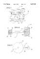
- FIG. 1illustrates a perspective view of a dishwasher embodying the features of the present invention.
- FIG. 2is a front plan view of a dishwasher embodying the features of the present invention, having a portion broken away to show the positioning of a motor and absorber of the present invention.
- FIG. 3is a side plan view of a motor and absorber system of the present invention.
- FIG. 4is a fragmentary front view of an absorber of the present invention having portions broken away to show threaded connections of the beam.
- FIG. 5is a top plan view of a motor and absorber of the present invention.
- a tuned dynamic vibration absorber 1is provided to absorb vibration from a vibrating mass.
- the vibrating masscan be, for example, an electric motor 10.
- the inventionis particularly suited for use with a dishwasher 12, as illustrated in FIG. 1.
- the dishwasher 12has an electric motor 10 as illustrated in FIG. 2.
- the motor 10is mounted in the bottom of the dishwasher 12 so that a rotor shaft 14 of the motor 10 is aligned on a vertical axis.
- the rotor shaft 14is connected to a pump 16.
- the motorhas a housing 18.
- the present inventionprovides an absorber 1 which reduces motor 10 vibration and related noise.
- the absorber 1, described in detail below,is preferably dimensioned so that the motor 10, the pump 16, and the absorber 1, when assembled together, can be positioned in the a tub 19 in the bottom of the dishwasher 12.
- the absorber 1could be used to reduce motor vibration in many applications.
- a single absorber 1which includes a beam 20 and a mass 22.
- the beam 20 and mass 22are configured to be externally mounted to the motor 10 so that the beam 20 is perpendicular to the rotational axis of the motor 10.
- the beam 20is an elongated member which can be a variety of shapes. However, the beam 20 is preferably straight and has a circular or rectangular cross-section for ease of design. The beam 20 of the embodiment illustrated has a circular cross-section.
- the beam 20is secured to the motor housing 18.
- the beam 20has a first threaded portion 24 which can be threaded into a threaded hole 26 in the motor housing 18.
- the beam 20can be secured threaded into a corner cleat (not shown) which is used to clamp a plurality of stator laminations together.
- the threaded portion 24would extend into a hole drilled parallel to the laminations.
- a nut portion 35 of the beam 20is preferably provided for engagement by a wrench. An assembler can thereby turn the first threaded portion 24 into the hole 26.
- the hole 26is oriented so that the beam 20 is securable perpendicularly to the rotational axis of the motor 20.
- the mass 22is secured to the beam 20 at an end opposite the connection to the motor 10.
- the mass 22is preferably generally cylindrical in shape.
- the mass 22is threaded to a second threaded portion 28 of the beam 20.
- the mass 22 and beam 20can be a single component.
- the mass 22preferably has ridges 30 forming a twelve-point configuration which can be engaged by a standard socket wrench.
- the inventiontakes advantage of the dynamic relationship between two mass-spring-damper systems: a primary system (the motor 10) and a secondary system (the absorber 1).
- the parameters of the secondary systempreferably are designed so that the natural frequency of the secondary system is "tuned", or matched, to the operating vibrational forcing frequency of the primary system so that the absorber operates about its maximum vibration absorption point.
- the resultis a deflection absorber 1 of the secondary system at its natural frequency producing a force equal to but out of phase (approximately 180 degrees at resonance) with the excitation force, the vibration of the motor 10 although there may be other reaction components in operational use. This reduces the force output at that frequency of the combined primary and secondary systems.
- FIG. 5illustrates the motion of the deflection of the absorber 1.
- the primary systemis the motor 10 which preferably operates on 60 Hz alternating current and has a rotational, or torsional, vibration at 120 Hz.
- the tuned absorber 1can be designed for use with other vibrating objects or for operation at other frequencies. For instance, it could be designed for use with a motor 10 that operates on 50 Hz alternating current and which has a 100 Hz vibration.
- the absorber 1is mounted externally to the motor 10 perpendicular to the axis of the motor 10, around which the torsional vibration motion is centered. Only one such absorber 1 is attached to the motor 10 in the present invention.
- the vibration absorber 1is preferably designed to provide an optimal initial absorbing force while minimizing sensitivity to system variability. As a result, the absorber 1 significantly reduces torsional vibration of the motor 10 and structure borne noise.
- the tuned absorber's dimensionsare designed so that the absorber's first natural frequency, a bending mode in a plane of the torsional vibration, is tuned to reduce the 120 Hz motor torsional vibration excitation force of the motor 10 (for a 60 Hz system).
- the absorber 1is mounted externally to increase its inertial effects. This optimizes the inertia ratio of the primary and secondary systems for preventing higher and lower frequency system resonances from interfering with proper operation of the tuned absorber 1. Since the inertia force is optimized, only one externally mounted absorber 1 is necessary.
- the absorber 1reduces the transmissibility of the combined absorber and motor system.
- Two degrees of freedomcan be presumed: the rotation of the motor 10 and the deflected motion of the absorber 1.
- the natural frequencies and transmissibility for a two degree of freedom translational systemare defined as: ##EQU1##
- the transmissibilityis the ratio of the primary system's force output to the forcing function force output.
- the equation for transmissibilityshows that as the forcing frequency approaches W2, the secondary system's natural frequency, the transmissibility goes to zero. In other words, the vibration output of the composite system per unit vibration input is reduced.
- the tuned dynamic vibration absorber 1can be modeled as a mass suspended from a cantilevered beam.
- the beam 20 stiffness, mass, dimensions, area moment of inertia and cantilevered mass 22are selected at specific values to tune the system's first bending mode (lowest natural frequency) to the frequency of vibration to be reduced.
- the moment of inertia for a beam 20 having a circular cross-sectioncan be calculated from the following formula where the beam's radius is represented by the term h: ##EQU2##
- the moment of inertiacan be calculated from the following formula where h and b represent the beam's thickness and width respectively: ##EQU3##
- the material, dimensions, geometry and mass of the absorber 1are selected in order to tune the first bending mode resonance of the system to a forcing function frequency, in this case, 120 Hz from torsional vibration of the motor 10, or alternatively 100 Hz.
- a forcing function frequencyin this case, 120 Hz from torsional vibration of the motor 10, or alternatively 100 Hz.
- the calculation for the first bending mode of a cantilevered beam 20 having a length L and a Circular cross-sectionis: ##EQU4##
- the tuned absorber 1 mass and geometryare designed to have an inertia around the axis which minimizes the effects of frequency tuning errors and the effects of corresponding side resonances. Also, the material of the beam 20 preferably resists fatigue stress for the deflection of the beam 20. The result is a robust single tuned absorber 1 designed with optimal vibration absorption.
- An important design parameteris the ratio of the motor 10 inertia to the absorber 1 inertia. This ratio determines the frequency span between the resonant frequencies immediately above and below the preferred design frequency, 120 Hz. The ratio is designed for a frequency span which minimizes amplification of the system's vibration due to the side resonances. Such a frequency span is dependent on the system's design and tolerances, damping factors affecting the side resonances and the tolerable performance deviation in the particular application.
- the inertia of the absorber 1is optimized by mounting it externally to the vibrating system. External mounting positions the absorber mass 22 farther from the center of gravity of the vibrating primary system, the motor 10, increasing the inertia of the absorber 1.
- the calculation for the inertia of a cylindrical mass 22 and beam about the motor center of gravity, where the center of gravity is assumed to be on the axis of rotation,is as follows:
- the parallel axis theoremadds the term mL 2 to each of the inertia calculations for the mass and rod.
- the L 2 termis critical for optimizing the inertia of the system. As the length of the mass center of gravity from the motor center of gravity is increased, the inertia of the mass 22 increases by the square of the distance. Therefore, small increases in this distance can result in large increases of the tuned absorber inertia. This also makes the system sensitive to the weight of the tuned absorber mass 22 since it is the constant that L is multiplied by.
- values for the beam 20 mass and dimensions and the quantity of the mass 22can be selected for given materials to provide an absorber 1 having the desired resonant frequency and inertia characteristics. It has been found that mass 20 having a weight of 0.5 pounds is adequate to provide a desirable sensitivity range. Furthermore, it has been found that a inertia ratio of the secondary mass to the primary mass for the system is 1:13.
- the first threaded portion 24is preferably tightened into the hole 26 to a predetermined torque value associated with a required joint stiffness so that the absorber 1 and motor 10 vibrate as one rigid component.
- An assemblercan use a wrench to turn the nut portion of the beam 20 into the hole 26 to the predetermined torque value.
Landscapes
- Engineering & Computer Science (AREA)
- General Engineering & Computer Science (AREA)
- Mechanical Engineering (AREA)
- Vibration Prevention Devices (AREA)
Abstract
Description
I.sub.external =I.sub.mass +mL.sub.mass.sup.2 +I.sub.beam +mL.sub.beam.sup.2
Claims (17)
Priority Applications (4)
| Application Number | Priority Date | Filing Date | Title |
|---|---|---|---|
| US08/291,167US5637938A (en) | 1994-08-16 | 1994-08-16 | Tuned dynamic vibration absorber |
| CA002155256ACA2155256A1 (en) | 1994-08-16 | 1995-08-03 | Tuned dynamic vibration absorber |
| EP95305660AEP0698750A1 (en) | 1994-08-16 | 1995-08-14 | Tuned dynamic vibration absorber |
| BR9503661ABR9503661A (en) | 1994-08-16 | 1995-08-15 | Vibration reduction device and vibration absorber |
Applications Claiming Priority (1)
| Application Number | Priority Date | Filing Date | Title |
|---|---|---|---|
| US08/291,167US5637938A (en) | 1994-08-16 | 1994-08-16 | Tuned dynamic vibration absorber |
Publications (1)
| Publication Number | Publication Date |
|---|---|
| US5637938Atrue US5637938A (en) | 1997-06-10 |
Family
ID=23119159
Family Applications (1)
| Application Number | Title | Priority Date | Filing Date |
|---|---|---|---|
| US08/291,167Expired - LifetimeUS5637938A (en) | 1994-08-16 | 1994-08-16 | Tuned dynamic vibration absorber |
Country Status (4)
| Country | Link |
|---|---|
| US (1) | US5637938A (en) |
| EP (1) | EP0698750A1 (en) |
| BR (1) | BR9503661A (en) |
| CA (1) | CA2155256A1 (en) |
Cited By (15)
| Publication number | Priority date | Publication date | Assignee | Title |
|---|---|---|---|---|
| US6267361B1 (en) | 2000-09-21 | 2001-07-31 | Carrier Vibrating Equipment, Inc. | Dynamic reaction reducer for isolated vibratory equipment |
| US6462440B1 (en)* | 1997-07-08 | 2002-10-08 | Mitsubishi Denki Kabushiki Kaisha | Vehicle alternator |
| US20040055410A1 (en)* | 2000-12-14 | 2004-03-25 | Bsh Bosch Und Siemens Hausgerate Gmbh | System for damping vibrations coming from a motor |
| US20050267511A1 (en)* | 1999-06-02 | 2005-12-01 | Marks Michael P | Intracorporeal occlusive device and method |
| US20060222505A1 (en)* | 2001-04-19 | 2006-10-05 | Ajay Sehgal | Rotor system vibration absorber |
| US20070131479A1 (en)* | 2005-12-08 | 2007-06-14 | Mark Brockman | Resonant frequency adjustor and method of utilizing the same |
| US20080029941A1 (en)* | 2006-08-04 | 2008-02-07 | Michael Idarecis | Hysteresis damping device for a vibratory body |
| US20110182535A1 (en)* | 2010-01-22 | 2011-07-28 | Baker Hughes Incorporated | Motor Shaft Vibration Isolator for Electric Submersible Pumps |
| US8851864B2 (en) | 2011-09-02 | 2014-10-07 | Baker Hughes Incorporated | Attenuating vibration in a submersible pump |
| US9366313B2 (en) | 2013-03-15 | 2016-06-14 | General Electric Company | Torsional resonance frequency adjustor |
| US20160380505A1 (en)* | 2015-06-26 | 2016-12-29 | Siemens Industry, Inc. | Electrodynamic machines, and method for reducing vibration of an electrodynamic machine |
| US9551398B2 (en) | 2013-03-15 | 2017-01-24 | General Electric Company | Torsional mode shifting |
| US9782054B2 (en) | 2015-01-13 | 2017-10-10 | Haier Us Appliance Solutions, Inc. | Pump assemblies and fluid circulation systems for dishwasher appliances |
| EP2083746B1 (en) | 2006-11-03 | 2018-01-10 | Koninklijke Philips N.V. | Vibration-canceling secondary resonator for use in a personal care appliance |
| US11933320B2 (en) | 2020-10-21 | 2024-03-19 | Haier Us Appliance Solutions, Inc. | Pump damper assembly and dishwasher appliance |
Families Citing this family (5)
| Publication number | Priority date | Publication date | Assignee | Title |
|---|---|---|---|---|
| DE10062367A1 (en)* | 2000-12-14 | 2002-06-20 | Bsh Bosch Siemens Hausgeraete | Arrangement for damping the vibration emanating from an engine |
| DE10062368A1 (en)* | 2000-12-14 | 2002-06-20 | Bsh Bosch Siemens Hausgeraete | Arrangement for damping the vibration emanating from an engine |
| DE10062369A1 (en)* | 2000-12-14 | 2002-06-20 | Bsh Bosch Siemens Hausgeraete | Arrangement for damping the vibrations emanating from an engine |
| DE10345605A1 (en)* | 2003-09-29 | 2005-05-04 | Siemens Ag | machine system |
| US11387705B2 (en)* | 2019-12-09 | 2022-07-12 | Dana Tm4 Inc. | Torsional mass tuned damper |
Citations (18)
| Publication number | Priority date | Publication date | Assignee | Title |
|---|---|---|---|---|
| US1834860A (en)* | 1930-02-24 | 1931-12-01 | Gen Electric | Dynamo electric machine |
| US1855570A (en)* | 1928-02-28 | 1932-04-26 | Edison Inc Thomas A | Vibration eliminating means |
| GB434355A (en)* | 1933-12-29 | 1935-08-29 | Howard Frederick Hobbs | Improvements in or relating to automatically-variable power transmission mechanism |
| US2237916A (en)* | 1938-08-19 | 1941-04-08 | Telefunken Gmbh | Electric motor mounting |
| US2484241A (en)* | 1947-11-28 | 1949-10-11 | Westinghouse Electric Corp | Vibration damper for dynamoelectric machines |
| DE864178C (en)* | 1949-09-03 | 1953-01-22 | Ferdinand Dr-Ing Marguerre | Device for reducing mechanical vibrations |
| US2953697A (en)* | 1958-12-30 | 1960-09-20 | Gen Electric | Magnetic core for dynamoelectric machines |
| DE1148108B (en)* | 1953-10-02 | 1963-05-02 | Clemens A Voigt | Vibration absorber made of a self-damped spring and a relatively small auxiliary mass connected to the spring |
| US3270221A (en)* | 1965-05-28 | 1966-08-30 | Paul B Shaffer | Motor vibration suppression mounting |
| US3337165A (en)* | 1965-03-26 | 1967-08-22 | Victor Company Of Japan | Vibration damping device |
| US3566993A (en)* | 1969-03-26 | 1971-03-02 | Nasa | Active vibration isolator for flexible bodies |
| US3668571A (en)* | 1969-05-10 | 1972-06-06 | Olympus Optical Co | Method for eliminating noise of an electric appliance and device therefor |
| GB2086007A (en)* | 1980-10-22 | 1982-05-06 | Minamidate Makoto | Vibration Damping Handle |
| EP0204330A2 (en)* | 1985-06-04 | 1986-12-10 | Nippon Kokan Kabushiki Kaisha | Dynamic vibration absorber |
| US4661731A (en)* | 1986-04-25 | 1987-04-28 | Sperry Corporation | Shield for fan motor for reducing structureborne noise and the external magnetic field |
| US4852848A (en)* | 1987-05-01 | 1989-08-01 | Kucera Richard J | Pipe vibration reducer |
| US4959568A (en)* | 1986-08-05 | 1990-09-25 | General Scanning, Inc. | Dynamically tunable resonant device with electric control |
| EP0552695A1 (en)* | 1992-01-21 | 1993-07-28 | ALENIA AERITALIA & SELENIA S.P.A. | Dynamic two frequency vibration damper |
Family Cites Families (2)
| Publication number | Priority date | Publication date | Assignee | Title |
|---|---|---|---|---|
| JPS55119248A (en)* | 1979-03-09 | 1980-09-12 | Toshiba Corp | Antivibration mechanism of rotary body |
| JPS599334A (en)* | 1982-07-05 | 1984-01-18 | Matsushita Electric Ind Co Ltd | Vibration absorbing device of motor-driven compressor |
- 1994
- 1994-08-16USUS08/291,167patent/US5637938A/ennot_activeExpired - Lifetime
- 1995
- 1995-08-03CACA002155256Apatent/CA2155256A1/ennot_activeAbandoned
- 1995-08-14EPEP95305660Apatent/EP0698750A1/ennot_activeCeased
- 1995-08-15BRBR9503661Apatent/BR9503661A/ennot_activeApplication Discontinuation
Patent Citations (18)
| Publication number | Priority date | Publication date | Assignee | Title |
|---|---|---|---|---|
| US1855570A (en)* | 1928-02-28 | 1932-04-26 | Edison Inc Thomas A | Vibration eliminating means |
| US1834860A (en)* | 1930-02-24 | 1931-12-01 | Gen Electric | Dynamo electric machine |
| GB434355A (en)* | 1933-12-29 | 1935-08-29 | Howard Frederick Hobbs | Improvements in or relating to automatically-variable power transmission mechanism |
| US2237916A (en)* | 1938-08-19 | 1941-04-08 | Telefunken Gmbh | Electric motor mounting |
| US2484241A (en)* | 1947-11-28 | 1949-10-11 | Westinghouse Electric Corp | Vibration damper for dynamoelectric machines |
| DE864178C (en)* | 1949-09-03 | 1953-01-22 | Ferdinand Dr-Ing Marguerre | Device for reducing mechanical vibrations |
| DE1148108B (en)* | 1953-10-02 | 1963-05-02 | Clemens A Voigt | Vibration absorber made of a self-damped spring and a relatively small auxiliary mass connected to the spring |
| US2953697A (en)* | 1958-12-30 | 1960-09-20 | Gen Electric | Magnetic core for dynamoelectric machines |
| US3337165A (en)* | 1965-03-26 | 1967-08-22 | Victor Company Of Japan | Vibration damping device |
| US3270221A (en)* | 1965-05-28 | 1966-08-30 | Paul B Shaffer | Motor vibration suppression mounting |
| US3566993A (en)* | 1969-03-26 | 1971-03-02 | Nasa | Active vibration isolator for flexible bodies |
| US3668571A (en)* | 1969-05-10 | 1972-06-06 | Olympus Optical Co | Method for eliminating noise of an electric appliance and device therefor |
| GB2086007A (en)* | 1980-10-22 | 1982-05-06 | Minamidate Makoto | Vibration Damping Handle |
| EP0204330A2 (en)* | 1985-06-04 | 1986-12-10 | Nippon Kokan Kabushiki Kaisha | Dynamic vibration absorber |
| US4661731A (en)* | 1986-04-25 | 1987-04-28 | Sperry Corporation | Shield for fan motor for reducing structureborne noise and the external magnetic field |
| US4959568A (en)* | 1986-08-05 | 1990-09-25 | General Scanning, Inc. | Dynamically tunable resonant device with electric control |
| US4852848A (en)* | 1987-05-01 | 1989-08-01 | Kucera Richard J | Pipe vibration reducer |
| EP0552695A1 (en)* | 1992-01-21 | 1993-07-28 | ALENIA AERITALIA & SELENIA S.P.A. | Dynamic two frequency vibration damper |
Non-Patent Citations (4)
| Title |
|---|
| Abstract of Japanese 55 119248 of Sep. 12, 1980.* |
| Abstract of Japanese 55-119248 of Sep. 12, 1980. |
| Abstract of Japanese 59 9334 of Jan. 18, 1984.* |
| Abstract of Japanese 59-9334 of Jan. 18, 1984. |
Cited By (19)
| Publication number | Priority date | Publication date | Assignee | Title |
|---|---|---|---|---|
| US6462440B1 (en)* | 1997-07-08 | 2002-10-08 | Mitsubishi Denki Kabushiki Kaisha | Vehicle alternator |
| US20050267511A1 (en)* | 1999-06-02 | 2005-12-01 | Marks Michael P | Intracorporeal occlusive device and method |
| US6267361B1 (en) | 2000-09-21 | 2001-07-31 | Carrier Vibrating Equipment, Inc. | Dynamic reaction reducer for isolated vibratory equipment |
| US20040055410A1 (en)* | 2000-12-14 | 2004-03-25 | Bsh Bosch Und Siemens Hausgerate Gmbh | System for damping vibrations coming from a motor |
| US20060222505A1 (en)* | 2001-04-19 | 2006-10-05 | Ajay Sehgal | Rotor system vibration absorber |
| US7153094B2 (en)* | 2001-04-19 | 2006-12-26 | Bell Helicopter Textron Inc. | Rotor system vibration absorber |
| US7753166B2 (en)* | 2005-12-08 | 2010-07-13 | Windsor Machine & Stamping Ltd | Resonant frequency adjustor and method of utilizing the same |
| US20070131479A1 (en)* | 2005-12-08 | 2007-06-14 | Mark Brockman | Resonant frequency adjustor and method of utilizing the same |
| US20080029941A1 (en)* | 2006-08-04 | 2008-02-07 | Michael Idarecis | Hysteresis damping device for a vibratory body |
| EP2083746B1 (en) | 2006-11-03 | 2018-01-10 | Koninklijke Philips N.V. | Vibration-canceling secondary resonator for use in a personal care appliance |
| US20110182535A1 (en)* | 2010-01-22 | 2011-07-28 | Baker Hughes Incorporated | Motor Shaft Vibration Isolator for Electric Submersible Pumps |
| US8382375B2 (en) | 2010-01-22 | 2013-02-26 | Baker Hughes Incorporated | Motor shaft vibration isolator for electric submersible pumps |
| US8851864B2 (en) | 2011-09-02 | 2014-10-07 | Baker Hughes Incorporated | Attenuating vibration in a submersible pump |
| US9366313B2 (en) | 2013-03-15 | 2016-06-14 | General Electric Company | Torsional resonance frequency adjustor |
| US9551398B2 (en) | 2013-03-15 | 2017-01-24 | General Electric Company | Torsional mode shifting |
| US9782054B2 (en) | 2015-01-13 | 2017-10-10 | Haier Us Appliance Solutions, Inc. | Pump assemblies and fluid circulation systems for dishwasher appliances |
| US20160380505A1 (en)* | 2015-06-26 | 2016-12-29 | Siemens Industry, Inc. | Electrodynamic machines, and method for reducing vibration of an electrodynamic machine |
| US9906092B2 (en)* | 2015-06-26 | 2018-02-27 | Siemens Industry, Inc. | Electrodynamic machines, and method for reducing vibration of an electrodynamic machine |
| US11933320B2 (en) | 2020-10-21 | 2024-03-19 | Haier Us Appliance Solutions, Inc. | Pump damper assembly and dishwasher appliance |
Also Published As
| Publication number | Publication date |
|---|---|
| BR9503661A (en) | 1996-05-28 |
| CA2155256A1 (en) | 1996-02-17 |
| EP0698750A1 (en) | 1996-02-28 |
Similar Documents
| Publication | Publication Date | Title |
|---|---|---|
| US5637938A (en) | Tuned dynamic vibration absorber | |
| US5394039A (en) | Electric motor mount having vibration damping | |
| US3330515A (en) | Machine installation | |
| US5810322A (en) | Apparatus for mounting a compressor | |
| JPS6024953Y2 (en) | Compressor elastic support device | |
| US20080006497A1 (en) | Vibration damping configuration | |
| US6091177A (en) | Spring mounting for an electric generator | |
| US3500083A (en) | Noise excitation suppression motor mounting system | |
| US3043970A (en) | Motor support and vibration isolation means | |
| EP0596043B1 (en) | An arrangement for supporting a fan housing by means of an elastic ring | |
| US3465182A (en) | Motor vibration suppression mounting system | |
| JPH1056754A (en) | Rotary electromechanical device | |
| MXPA95003513A (en) | Tuned dynamic vibration absorber | |
| US20140166844A1 (en) | Frequency Altering Brace For An Electric Motor | |
| US11387705B2 (en) | Torsional mass tuned damper | |
| KR102824019B1 (en) | Compressor | |
| JP2658340B2 (en) | Dehydration washing machine | |
| KR950009617Y1 (en) | Apparatus to reduce vibration for single-phase motor | |
| CN222802660U (en) | Motor front cover assembly, motor and clothing processing equipment | |
| JPS585486A (en) | Vibration attenuator for rotary enclosed motor compressor | |
| US3261543A (en) | Suspension and vibration-damping device for fans | |
| JP4150455B2 (en) | Washing machine with improved suspension means for a laundry assembly | |
| JPH0775269A (en) | Permanent magnet motor rotor | |
| JPH0437280Y2 (en) | ||
| JP2714818B2 (en) | Juan device |
Legal Events
| Date | Code | Title | Description |
|---|---|---|---|
| AS | Assignment | Owner name:WHIRLPOOL CORPORATION, MICHIGAN Free format text:EACH ASSIGNS AN UNDIVIDED ONE-HALF OF THE ENTIRE INTEREST;ASSIGNORS:DEBRECHT, DOUGLAS C.;WELLS, LARRY B.;DOHOGNE, L. RANNEY;AND OTHERS;REEL/FRAME:007281/0001 Effective date:19940826 Owner name:EMERSON ELECTRIC CO., MISSOURI Free format text:EACH ASSIGNS AN UNDIVIDED ONE-HALF OF THE ENTIRE INTEREST;ASSIGNORS:DEBRECHT, DOUGLAS C.;WELLS, LARRY B.;DOHOGNE, L. RANNEY;AND OTHERS;REEL/FRAME:007281/0001 Effective date:19940826 Owner name:WHIRLPOOL CORPORATION, MICHIGAN Free format text:ASSIGNMENT OF ASSIGNORS INTEREST;ASSIGNOR:VUKORPA, VICTOR M.;REEL/FRAME:007194/0362 Effective date:19940831 Owner name:EMERSON ELECTRIC CO., MISSOURI Free format text:ASSIGNMENT OF ASSIGNORS INTEREST;ASSIGNOR:VUKORPA, VICTOR M.;REEL/FRAME:007194/0362 Effective date:19940831 | |
| STCF | Information on status: patent grant | Free format text:PATENTED CASE | |
| FPAY | Fee payment | Year of fee payment:4 | |
| FPAY | Fee payment | Year of fee payment:8 | |
| FPAY | Fee payment | Year of fee payment:12 | |
| AS | Assignment | Owner name:NIDEC MOTOR CORPORATION, MISSOURI Free format text:ASSIGNMENT OF ASSIGNORS INTEREST;ASSIGNOR:EMERSON ELECTRIC CO.;REEL/FRAME:025651/0747 Effective date:20100924 |