US5637099A - Needle handling apparatus and methods - Google Patents
Needle handling apparatus and methodsDownload PDFInfo
- Publication number
- US5637099A US5637099AUS08/257,739US25773994AUS5637099AUS 5637099 AUS5637099 AUS 5637099AUS 25773994 AUS25773994 AUS 25773994AUS 5637099 AUS5637099 AUS 5637099A
- Authority
- US
- United States
- Prior art keywords
- cap member
- basin
- interior
- needle
- shaped member
- Prior art date
- Legal status (The legal status is an assumption and is not a legal conclusion. Google has not performed a legal analysis and makes no representation as to the accuracy of the status listed.)
- Expired - Fee Related
Links
- 238000000034methodMethods0.000titleclaimsdescription6
- 239000000758substrateSubstances0.000claimsabstractdescription17
- 238000005192partitionMethods0.000claimsdescription39
- 230000002093peripheral effectEffects0.000claimsdescription13
- 238000010276constructionMethods0.000claimsdescription4
- 230000005484gravityEffects0.000claimsdescription2
- 230000000694effectsEffects0.000claims1
- 230000036541healthEffects0.000description15
- 244000241796Christia obcordataSpecies0.000description6
- 239000012530fluidSubstances0.000description6
- 239000002874hemostatic agentSubstances0.000description5
- 238000004519manufacturing processMethods0.000description4
- 239000000853adhesiveSubstances0.000description3
- 230000001070adhesive effectEffects0.000description3
- 210000001367arteryAnatomy0.000description3
- 210000003462veinAnatomy0.000description3
- 239000004793PolystyreneSubstances0.000description2
- 210000001124body fluidAnatomy0.000description2
- 239000010839body fluidSubstances0.000description2
- 238000002347injectionMethods0.000description2
- 239000007924injectionSubstances0.000description2
- 229920000058polyacrylatePolymers0.000description2
- 229920000515polycarbonatePolymers0.000description2
- 239000004417polycarbonateSubstances0.000description2
- 229920002223polystyrenePolymers0.000description2
- 229920001169thermoplasticPolymers0.000description2
- 239000004416thermosoftening plasticSubstances0.000description2
- 208000030507AIDSDiseases0.000description1
- 208000035473Communicable diseaseDiseases0.000description1
- 239000004743PolypropyleneSubstances0.000description1
- FAPWRFPIFSIZLT-UHFFFAOYSA-MSodium chlorideChemical compound[Na+].[Cl-]FAPWRFPIFSIZLT-UHFFFAOYSA-M0.000description1
- 241000700605VirusesSpecies0.000description1
- 239000002390adhesive tapeSubstances0.000description1
- 230000004075alterationEffects0.000description1
- 230000003466anti-cipated effectEffects0.000description1
- 230000008901benefitEffects0.000description1
- 230000000903blocking effectEffects0.000description1
- 238000004891communicationMethods0.000description1
- 201000010099diseaseDiseases0.000description1
- 208000037265diseases, disorders, signs and symptomsDiseases0.000description1
- 239000003814drugSubstances0.000description1
- 208000002672hepatitis BDiseases0.000description1
- 208000015181infectious diseaseDiseases0.000description1
- 208000014674injuryDiseases0.000description1
- 239000007788liquidSubstances0.000description1
- 238000012423maintenanceMethods0.000description1
- 239000000463materialSubstances0.000description1
- 230000013011matingEffects0.000description1
- 238000012986modificationMethods0.000description1
- 230000004048modificationEffects0.000description1
- 239000002991molded plasticSubstances0.000description1
- 238000000465mouldingMethods0.000description1
- 239000004033plasticSubstances0.000description1
- 229920003023plasticPolymers0.000description1
- -1polypropylenePolymers0.000description1
- 229920001155polypropylenePolymers0.000description1
- 230000002035prolonged effectEffects0.000description1
- 239000012858resilient materialSubstances0.000description1
- 238000007789sealingMethods0.000description1
- 238000000926separation methodMethods0.000description1
- 230000007480spreadingEffects0.000description1
- 238000003892spreadingMethods0.000description1
- 238000005728strengtheningMethods0.000description1
- 230000001225therapeutic effectEffects0.000description1
- 239000012780transparent materialSubstances0.000description1
- 230000008733traumaEffects0.000description1
Images


Classifications
- A—HUMAN NECESSITIES
- A61—MEDICAL OR VETERINARY SCIENCE; HYGIENE
- A61M—DEVICES FOR INTRODUCING MEDIA INTO, OR ONTO, THE BODY; DEVICES FOR TRANSDUCING BODY MEDIA OR FOR TAKING MEDIA FROM THE BODY; DEVICES FOR PRODUCING OR ENDING SLEEP OR STUPOR
- A61M5/00—Devices for bringing media into the body in a subcutaneous, intra-vascular or intramuscular way; Accessories therefor, e.g. filling or cleaning devices, arm-rests
- A61M5/178—Syringes
- A61M5/31—Details
- A61M5/32—Needles; Details of needles pertaining to their connection with syringe or hub; Accessories for bringing the needle into, or holding the needle on, the body; Devices for protection of needles
- A61M5/3205—Apparatus for removing or disposing of used needles or syringes, e.g. containers; Means for protection against accidental injuries from used needles
- A—HUMAN NECESSITIES
- A61—MEDICAL OR VETERINARY SCIENCE; HYGIENE
- A61M—DEVICES FOR INTRODUCING MEDIA INTO, OR ONTO, THE BODY; DEVICES FOR TRANSDUCING BODY MEDIA OR FOR TAKING MEDIA FROM THE BODY; DEVICES FOR PRODUCING OR ENDING SLEEP OR STUPOR
- A61M5/00—Devices for bringing media into the body in a subcutaneous, intra-vascular or intramuscular way; Accessories therefor, e.g. filling or cleaning devices, arm-rests
- A61M5/14—Infusion devices, e.g. infusing by gravity; Blood infusion; Accessories therefor
- A61M5/158—Needles for infusions; Accessories therefor, e.g. for inserting infusion needles, or for holding them on the body
- A61M2005/1581—Right-angle needle-type devices
- A—HUMAN NECESSITIES
- A61—MEDICAL OR VETERINARY SCIENCE; HYGIENE
- A61M—DEVICES FOR INTRODUCING MEDIA INTO, OR ONTO, THE BODY; DEVICES FOR TRANSDUCING BODY MEDIA OR FOR TAKING MEDIA FROM THE BODY; DEVICES FOR PRODUCING OR ENDING SLEEP OR STUPOR
- A61M5/00—Devices for bringing media into the body in a subcutaneous, intra-vascular or intramuscular way; Accessories therefor, e.g. filling or cleaning devices, arm-rests
- A61M5/14—Infusion devices, e.g. infusing by gravity; Blood infusion; Accessories therefor
- A61M5/158—Needles for infusions; Accessories therefor, e.g. for inserting infusion needles, or for holding them on the body
- A61M2005/1583—Needle extractors
- A—HUMAN NECESSITIES
- A61—MEDICAL OR VETERINARY SCIENCE; HYGIENE
- A61M—DEVICES FOR INTRODUCING MEDIA INTO, OR ONTO, THE BODY; DEVICES FOR TRANSDUCING BODY MEDIA OR FOR TAKING MEDIA FROM THE BODY; DEVICES FOR PRODUCING OR ENDING SLEEP OR STUPOR
- A61M25/00—Catheters; Hollow probes
- A61M25/01—Introducing, guiding, advancing, emplacing or holding catheters
- A61M25/06—Body-piercing guide needles or the like
- A61M25/0612—Devices for protecting the needle; Devices to help insertion of the needle, e.g. wings or holders
- A61M25/0631—Devices for protecting the needle; Devices to help insertion of the needle, e.g. wings or holders having means for fully covering the needle after its withdrawal, e.g. needle being withdrawn inside the handle or a cover being advanced over the needle
Definitions
- This inventionrelates to apparatus and methods for safely removing a medical needle inserted into an implanted access device under the skin of a patient and the disposing of the medical needle.
- An access devicewhich includes a portal and a small, flexible, hollow tubing (i.e., a catheter) extending from the portal and into a vessel where it remains for a prolonged period of time such that fluids may be repeatedly or continuously infused through the catheter into the vessel.
- Other parts of the bodycan be accessed other than a vein or artery with the implanted access device. Removal of body fluids may also be handled through the access device.
- the portal of the access deviceis implanted under the skin and has a septum through which a medical needle can be inserted to provide fluid communication between the medical needle and the vein, artery, or other body location.
- the septumis self-sealing, i.e., the septum is composed of a resilient material that presses on the shaft of the medical needle that is inserted in the septum. The pressure by the septum on the medical needle results in a force resisting the withdrawal of the needle from the septum, thereby making it necessary for a health professional to hold the access device down against the patient as the medical needle is withdrawn therefrom.
- the portali.e., the structure defining the chamber in conjunction with the septum of the access device
- withdrawing the medical needle from the septummay cause the medical needle to accidentally prick or strike the health professional's finger.
- a medical needlesuch as a hypodermic needle or a butterfly needle, that has been exposed to a body fluid of a patient with an infectious disease, can pose a health risk to health professionals if the needle is not properly removed and disposed of using an apparatus suitable for safely handling such medical needles.
- a medical needle that has been used on a patient with hepatitis B or HIV (or AIDS) virusif allowed to accidentally prick the skin of a health professional, may transmit the disease to that health professional.
- the present inventionmeets a need for an apparatus for removing and isolating a medical needle
- the apparatushas a lower self-closing passageway wherein a needle-removal device, such as a hemostat, forceps, locking tweezers, and the like, can be used to draw a medical needle through the passageway to isolate the medical needle in the apparatus such that the medical needle cannot independently extend outside the apparatus to accidentally prick a health professional.
- a needle-removal devicesuch as a hemostat, forceps, locking tweezers, and the like
- an upper self-closing passagewayis provided to selectively allow passage of the needle-removal device but not the medical needle.
- the present inventionprovides an apparatus for safely handling a needle (i.e., medical needle), for example, in removing the medical needle from a substrate, such as the skin of patient or an implanted access device.
- the apparatushas a distal end and a proximal end and comprises a body, a cap member defining an opening therein and connected to the body to define an interior, and a lower yieldable partition member, preferably a basin-shaped member, connected to the body wherein the cap member is distal to the body.
- the basin-shaped memberis comprised of one or more yieldable flaps or fingers.
- the basin-shaped membermay have any of a plurality of configurations, including flat, V-shaped, dome-shaped, or conical-shaped.
- proximalrefers to a direction towards the substrate and the term “distal” refers to a direction away from the substrate.
- the basin-shaped member(lower yieldable partition member) defines a self-closing passageway and preferably has a rim disposed within the interior of the body intermediate the cap member and the proximal end of the apparatus. The apical end of the basin-shaped member faces the distal end of the apparatus.
- self-closingrefers to the ability of the passageway to return to its normally closed configuration after a force that deforms the passageway is removed. The normally closed configuration prevents a medical needle from independently extending therethrough.
- a snap arrangementis provided to mount the body to the cap member wherein the lower yieldable partition member is held between portions of the body and the cap member.
- the present inventionalso provides an apparatus for safely handling a needle wherein the apparatus has a distal end and a proximal end and comprises a body, a cap member defining an opening therein, and an upper yieldable partition member connected to the cap member.
- the cap memberis connected to and disposed distally to the body to define an interior.
- the upper yieldable partition memberpreferably has two generally rectangular flaps yieldably connected to the cap member.
- the generally rectangular flapspreferably extend obliquely toward each other and toward the interior. Each flap terminates at a free edge, and the free edges of the flaps are proximate to and preferably offset from each other in the direction toward the proximal end.
- the upper yieldable partition memberdefines a self-closing passageway which can be disposed within the interior intermediate the distal end and the proximal end of the apparatus, or preferably, proximate the distal end.
- the offset configurationis optional but it may lead to ease of manufacturing in the case of molded plastics where the flaps need to be appropriately positioned to prevent the passage of the medical needle.
- the apparatus for safely handling a medical needle of the present inventionis particularly adapted for use in removing a medical needle that has been inserted into an implanted access device for the periodical or continuous infusing or withdrawal of a fluid through the medical needle.
- the apparatuscan be used to completely isolate the medical needle from the health professional.
- a hemostatcan be used to remove the medical needle with the apparatus disposed between the medical needle and the health professional.
- the health professionalcan remove the medical needle from the implanted access device and deposit the medical needle in a cavity in the apparatus, which prevents the medical needle from independently and accidentally protruding or extending therethrough, all the while keeping at least part of the apparatus between the medical needle and the health professional.
- the lower yieldable partition member having the self-closing passagewayis preferably non-planar, having an apical end facing the interior of the cavity wherein the medical needle is disposed.
- the medical needleis kept from the open ends of the apparatus and the risk of accidentally exposing the health professional to the contaminated medical needle is further reduced.
- the medical needlecannot easily pass back through the lower non-planar self-closing passageway due to its apical configuration and orientation relative to the medical-needle-receiving cavity.
- Such a self-closing passagewayis a "one-way passageway" because it is relatively easy to draw a medical needle into the interior of the cavity through the self-closing passageway but more difficult to move a medical needle in the other direction.
- the upper yieldable partition memberallows passage of the medical tool to grasp the needle during removal from the access device, while preventing passage of medical needle.
- the basin-shaped memberfacilities the assembly of the apparatus because the basin-shaped member is self-centering when placed on the proximal end of the cap member with the apical end facing the cap member.
- the apparatusis composed of identical halves. This simplifies the tooling cost and inventory cost for parts during the manufacturing process.
- the apparatus of the present inventioncan be applied to implanted access devices of various sizes because an adaptor according to the present invention can be used to adapt the apparatus for application on a smaller implanted access device.
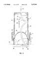
- FIG. 1is an isometric view of a first preferred embodiment of an apparatus of the present invention
- FIG. 2is a partial cross-sectional view of the embodiment of FIG. 1 deployed over an implanted access device;
- FIG. 3is a partial cross-sectional view at a right angle to that of FIG. 2, showing the removal of a medical needle from the implanted access device;
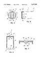
- FIG. 4is a top view of a cap member of the embodiment of FIG. 1;
- FIG. 5is a cross-sectional view along the line 5--5 of FIG. 4;
- FIG. 6is a partial cross-sectional view along the line 6--6 of FIG. 4;
- FIG. 7is an enlarged cross-sectional view showing details along the line 5--5 of FIG. 4;
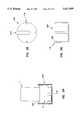
- FIG. 8is a top view of the basin-shaped member of FIG. 1;
- FIG. 9is an enlarged view showing details of a portion of FIG. 8;
- FIG. 10is a cross-sectional view along the line 10--10 of FIG. 8;
- FIG. 11is a top view of the body of the embodiment of FIG. 1;
- FIG. 12is an enlarged cross-sectional view along the line 12--12 of FIG. 11;
- FIG. 13is an enlarged cross-sectional view along the line 13--13 of FIG. 11;
- FIG. 14is a cross-sectional view of a second preferred embodiment of the apparatus of the present invention.
- FIG. 15is a cross-sectional view of one identical half of the embodiment of FIG. 14;
- FIG. 16is a cross-sectional view of a third preferred embodiment of the apparatus of the present invention, with the basin-shaped member and the cover member removed for clarity;
- FIG. 17is a cross-sectional view of the two halves along the line 17--17 of FIG. 16 with portions removed for clarity;
- FIG. 18is a top view of a cover member for use with the structure of FIG. 16;
- FIG. 19is a basin-shaped member for use with the structure of FIG. 16;
- FIG. 20is a partial cross-sectional view showing a preferred embodiment of an adaptor with an apparatus of FIG. 1 wherein details of the apparatus of FIG. 1 are shown schematically;
- FIG. 21is a plan view of the adaptor of FIG. 20;
- FIG. 22is a side view of the adaptor of FIG. 20;
- FIG. 23is a top view showing the adaptor of FIG. 20 deployed underneath a butterfly needle;
- FIG. 24is a partial cross-sectional view showing a second preferred embodiment of an adaptor of the present invention deployed with an apparatus of FIG. 1, wherein details of the apparatus of FIG. 1 and the needle are not shown for clarity;
- FIG. 25is a plan view of the adaptor of FIG. 24.
- FIG. 26is a side view of the adaptor of FIG. 24.
- the present inventionprovides an apparatus and method for safely handling medical needles engaged with the septum of an access device implanted under the skin of a patient.
- Two spaced apart yieldable partition membersdefine a cavity for safely containing a medical needle.
- a needle-removal devicepasses through both partition members to grasp the medical needle and withdraw the medical needle past the lower partition member.
- the lower partition memberis self-closing to close the lower end of the apparatus.
- the needle-removal devicereleases the medical needle in the cavity of the apparatus, and is withdrawn from the upper partition member.
- the upper partition memberis self-closing to close the upper partition member. While the terms "upper” and “lower” are used herein, it is to be appreciated that such orientation relative to the vertical occurs in one preferred mode of operation.
- the apparatus of the present inventionis useable at any angle to the vertical, including perpendicular.
- FIGS. 1-13A first preferred embodiment of this invention is shown in FIGS. 1-13.
- the apparatus 1has a body construction with an accessible interior for containing a medical needle during use.
- apparatus 1includes a body 2, a cap member 4, and a basin-shaped or cup-shaped member 6.
- the apparatushas a proximal end 8 and a distal end 10.
- the cap member 4has a proximal end 12 and a distal end 14 and is disposed generally distal to the body 2.
- the cap member 4is generally cylindrical and has a peripheral wall 16 and a distal end wall 18 defining the interior boundaries.
- An opening 20is preferably located on the distal end wall 18 proximate the distal end 14 of the cap member 4.
- the opening 20is configured to permit a needle-removal device to pass therethrough, such as a hemostat or another gripping device.
- the opening 20can simply be edges defining an opening to permit the free passage of the needle-removal device, or it can include a structure that guards the opening to permit a needle-removal device to pass therethrough but prevent the medical needle to independently (i.e. without the deliberate manipulation by an operator) extend or exit therethrough. This structure forms an upper (or distal) yieldable partition member.
- a preferred structure for guarding the opening 20 to render it self-closableincludes a flap 22 integrally and yieldably connected to the rest of the cap member 4 such that a needle-removal device can be forcefully pressed against the flap 22 to pass thereby.
- the flap 22is generally rectangular and resiliently flexible (or yieldable to pressure) to provide a self-closing passageway into the interior of the cap member. Upon withdrawal of the needle-removal device, the resilient nature of the flap 22 returns the flap to its normally closed position.
- the flap 22can extend toward the interior of cap member 4 to facilitate the selective passage configuration with respect to the medical needle and the needle-removal device.
- a flat flap 22 extending perpendicularly to the axis of the cap membermay be utilized as a self-closing passageway.
- each flap 22there are two flaps 22 extending toward each other, preferably obliquely and toward the interior of the cap member 4, each terminating at a free edge 24 opposite from where the flap is connected to the end wall 18.
- Each flap 22has two side edges 26 joined to the free edge 24, defining the flap.
- the free edges 24 of the two flaps 22are proximate to each other and are substantially parallel.
- the flaps 22are slightly off-set (e.g., about 0.04 in. to 0.08 in.) in the direction toward the proximal end 12 such that the free edge 24 of one flap is at a longitudinal location different from that of the free edge of the other flap.
- These two free edges 24A,24Bare aligned along a plane extending through the proximal end 12 and the distal end 14 so that viewing from the distal end of the cap member, the free edges 24A,24B substantially coincide (see for example, FIG. 4).
- the size of the gap between the free edges from a vertical (or end view) perspectivee.g., about 0.020 in. to 0.025 in.
- the diameter of a shaft of a medical needlee.g., about 0.028 in. for 22 gauge needle
- the length of the free edges 24 of the flapsare preferably of a dimension such that the side edges 26 are proximate the cylindrical wall 16 of the cap member so as to reduce the risk of a medical needle extending through a gap 28 defined by the side edges 26 of the flaps and a side edge of the opening.
- the opening 20can further include lips 30 extending from the wall 16 of the cap member 4 radially inward proximate the end wall 16. The lips 30 are oriented generally perpendicular to the free edges 24 of the flaps 22 to prevent a medical needle from sliding along the wall of the cap member to extend into a space (or gap) 28 distal to the flaps and proximate the side edges 24 thereof.
- the cap member 4is connected, preferably rotatably engaged, to the body 2.
- the term "connected" when applied to the relation between the cap member 4, the basin-shaped member 6 having the self-closing passage, and/or the body 2includes a rigid connection between the parts, whether integrally formed, or intimate engagement in which one part can move, such as by rotation, in relation to the other part.
- the rotation of the cap member 4 relative to the body 2facilitates the positioning of a needle-removal device, such as a hemostat or locking tweezers for passing through the cap member.
- the cap member 4can be connected to the body 2 by arrangements of corresponding matingly engageable fastening structures effective to fasten the cap member 4 and the body 2 without the need of an externally applied securing device such as adhesive, tape, clamp, screw, nut with bolt, and the like.
- the corresponding matingly engageable fastening structures of the cap member 4 and the body 2can be of a configuration such that they can be fitted together with a snap-fit.
- the matingly engageable fastening structures of the snap-fitted apparatusresists the separation of the cap member 4 from the body 2 but permits relative rotation thereof.
- a generally annular lip 32for such a mating engagement with wedge-shaped members (shown as 58 in FIG. 12) of the body 2.
- slits 34are provided on the portion of the cap member at its proximal end to increase the flexibility thereof.
- the annular lip 32 disposed on the proximal, exterior surface of the cap member 4preferably is beveled to have a larger diameter on its distal edge than its proximal edge to facilitate slipping the annular lip past the wedge-shaped member for snap-fit engagement.
- the basin-shaped member 6defines a self-closing passageway 35 and has an annular rim 36.
- the basin-shaped member 6forms a lower (or proximal) yieldable partition member with self-closing capability.
- the lower yieldable partition memberis one-directional with respect to the passage of a medical needle during use, meaning that entry of the medical needle is easier than exiting.
- the one-directional featuremakes it difficult or impossible for the medical needle to pass in the opposite direction.
- a flat configuration for member 6is possible where member 6 is still self-closing. In that case, additional structure may be necessary to make the flat member one-directional, if desired.
- the basin-shaped memberhas a plurality of yieldable (or resiliently flexible), generally umbrella-section-shaped members (or fingers) 40 extending therefrom to cumulate at an apical end 42 to have a dome-shaped appearance.
- Each finger 40further has side edges 44 extending inwardly and toward the distal end 42 of the apparatus to cumulate at the apical end, which faces the distal end 10 of the apparatus.
- the side edges of two adjacent fingersdefine a slot 45 therebetween.
- the side edges 44 and tips 46 of neighboring fingersdo not touch each other so as to permit free movement of the fingers.
- the tips 46 of the fingersare generally aligned and do not form sharp angles with each other when viewed from the side.
- the tips 46 of the fingersdefine a generally circular opening 48 (having a diameter of, for example, 0.11 in.) through which the tip of the needle-removal device can extend to spread apart the tips 46 of the fingers.
- the fingers 40will yield to permit a needle-removal device to pass therethrough to grasp a medical needle and permit the medical needle to be pulled by the needle-removal device into the cavity 38 distal to the fingers in the apparatus.
- the fingersare proximate to each other so as to form a one-way partition through which a medical needle can be drawn.
- Such a one-way partitioncan prevent a medical needle from independently passing therethrough in the opposite direction, for example, by rotational or vibrational movement of the apparatus.
- the non-planar configurationprovides for an easier passage of a medical needle toward the apical end 42 from below the basin-shaped member 6 as shown in FIGS. 2 and 3, than in an opposite direction.
- other non-planar shapes producing a one-way valveare possible other than the curved configuration shown, including generally planar fingers defining a conical shape, for example.
- basin-shaped member 6does not have to be generally symmetrical about the longitudinal axis of the apparatus 1.
- basin-shaped member 6can have a single flexible finger or flap, or two opposed fingers or flaps, such as shown in connection with cap member 4.
- the basin-shaped member 6has an odd number of fingers 40 so that no two slits 45 between the fingers are aligned in a straight line.
- butterfly needlesi.e., medical needles equipped with butterfly wings for ease of handling
- the butterfly wings of a butterfly needleare generally aligned in a plane during use, such a finger configuration, by blocking the butterfly wings, greatly reduces the risk of a butterfly needle independently passing through the basin-shaped member 6.
- elevated elements 47such as V-shape ridges, for strengthening the tips mechanically.
- elevated elements 47provide an added longitudinal dimension proximate the tips of the fingers so that even if two adjacent fingers are slightly misaligned or offset, the risk of a medical needle in the cavity 38 distal to the fingers 40 independently extending proximally through the basin-shaped member 6 is reduced.
- the rim 36is disposed in the interior of the body 2 intermediate the cap member 4 and the proximal end 8 of the apparatus 1.
- the self-closing passageway 35is generally disposed inside the cavity 38 in the interior of the cap member 4 intermediate the proximal end and distal end of the apparatus.
- the self-closing passageway 35is also disposed generally in the interior of the body 2, although it is to be appreciated that the basin-shaped member 6 may have a longitudinal dimension large enough that the apical end 42 extends distally past the distal end 54 of the body.
- the rim 36has an annular skirt 50 extending proximally for rotationally engaging a distally-extending, annular lip (shown as 60 in FIG.
- the inside diameter of the rim 36 of the basin-shaped member 6is slightly smaller than the inside diameter of the proximal portion of the peripheral wall 16 of the cap member 4 and the annular skirt 50 has an outside diameter larger than the inside diameter of the same peripheral wall so that during assembly of the apparatus 1, the basin-shaped member 6 can be positioned on the cap member 4 easily due to the self-centering nature of the basin-shaped member. Because the center of gravity of the basin-shaped member 6 is intermediate the rim 36 and the apical end 42, as the basin-shaped member is laid on the proximal end 12 of the cap member 4 with the proximal end 12 facing upward, the gravitational force draws the fingers 40 of the basin-shaped member into the interior defined by the peripheral wall 16 of the cap member. In this way, the nonplanar nature of the basin-shaped member 6 significantly increases the ease of assembly of apparatus 1 before use.
- the body 2has a proximal end 52, a distal end 54, and walls 56A,56B defining interior boundaries thereof.
- wedge-shaped members 58which correspond to the proximal generally annular lip 32 of the cap member 4 for matingly engaging therewith to provide snap-fit fastening of the cap member 4 to the body 2 without externally applied fastening arrangements such as an adhesive, and the like.
- An interior annular lip 60is provided proximal and more to the interior in relation to the wedge-shaped members 58.
- the annular lip 60 of the body 2extends distally for engaging the inner surface of the annular skirt 50 of the basin-shaped member 6.
- the annular lip 32 at the proximal end of the cap member 4is disposed and rotationally confined between the wedge-shaped members 58 of the body and the annular interior lip 60 of the body. Furthermore, the rim 36 of the basin-shaped member 6 is rotationally held (or confined) between the generally annular lip 32 of the cap member 4 and the annular interior lip 60 of the body.
- the body 2further has a proximally extending portion 62 having dimensions slightly larger than the dimensions of the implanted access device so that a medical needle that has been inserted into the implanted access device is disposed in an interior space defined by the portion. Furthermore, provided on the proximal portion 62 proximate the proximal end of the apparatus are notches 63 through which a tubing 74 for infusing or withdrawal of liquid to the implanted access device can extend. The notches also allow for receipt of the catheter under the skin.
- the apparatus 1is pressed onto the skin above the portal 66 of the implanted access device 68.
- a needle-removal device 70such as a hemostat or a pair of locking tweezers can be inserted through the opening defined by the flaps 22 and the lips 30 on the distal end of the cap member 4.
- the needle-removal device 70flexes and slightly deforms the flaps 22 as it is inserted into the cavity 38 defined by the end wall and the peripheral wall of the cap member.
- the needle-removal device 70can be used to grasp the medical needle 64, for example, the butterfly wings 72 of a butterfly needle. As the needle-removal device 70 is manipulated to grasp and remove the medical needle from the septum 76 of the implanted access device, the fingers 40 of the basin-shaped member 6 are flexed to yield to the movement of the needle-removal device. The needle-removal device 70 can then be withdrawn, still grasping the medical needle, so that the medical needle is drawn past the apical end 42 of the basin-shaped member 6 (i.e., the tips of the fingers thereof) into the cavity 38 defined by the cap member and the basin-shaped member.
- the medical needlecan then be released from the needle-removal device and the needle-removal device is withdrawn from the apparatus 1. In this manner, the medical needle is trapped in the cavity 38.
- the apparatus, with the medical needle confined therein,can then be properly disposed of without the risk of the medical needle independently extending outside the apparatus and posing a health risk to an operator. It is anticipated that the apparatus be disposable with the used medical needle inside.
- FIGS. 14-15depict another preferred embodiment of the present invention.
- apparatus 1'is preferably composed of two essentially, more preferably exactly, identical halves, i.e., a proximal half 80 and a distal half 82.
- the distal half 82functions as a cap member 4' having a peripheral wall 16' defining an interior space.
- the distal halfhas a basin-shaped member 84 having a self-closing passageway connected to the peripheral wall on the inside surface thereof, intermediate the distal end 14' and the proximal end 12' of the distal half 82.
- the proximal half 80has a peripheral wall defining an interior space and has a basin-shaped member 6' connected to the peripheral wall on the interior surface thereof intermediate the distal end and the proximal end of the proximal half.
- the proximal portion 86 of the proximal half 80preferably has a wall that diverges slightly for spreading the pressure evenly on the skin of a patient.
- the distal end 14' of the distal member 82preferably has a wall that diverges slightly to facilitate the introduction of a needle-removal device thereinto.
- the two halvescan be secured together, for example, by securing arrangements such as an adhesive, adhesive tape, a clamp, a matingly engageable arrangement similar to arrangements 90 shown in FIG. 16-17 below, and the like.
- the basin-shaped members of the two halvesAfter the two halves are secured together, the basin-shaped members of the two halves have their respective apical ends 42' extending toward each other.
- This configurationpermits a medical needle to be drawn into a cavity 38' defined between the peripheral walls and the basin-shaped members 6' of the two halves by passing through the self-closing passageway defined by the basin-shaped member 6' of the proximal half 80.
- the basin-shaped member 6'can have a dome-shaped configuration similar to that shown in FIGS. 8-10.
- An alternativeis a generally conical-basin-shaped member having fingers 40' that are generally straight as those shown in FIGS. 14 and 15.
- the fingersare shaped like generally isosceles triangles with their bases 88 yieldably connected to the interior wall and apical ends 42' extending in a direction toward a cavity 38' defined between the basin-shaped member 6' and the walls of the two halves.
- the tips of the fingersare slightly spaced apart to facilitate the introduction of a needle-removal device or the withdrawal of a medical needle therethrough into the cavity 38'.
- the diverging portion of the proximal halfhas notches 63' through which a medical tubing connected to the medical needle and/or portal can extend therethrough.
- FIGS. 16-19Another preferred embodiment having corresponding halves 89A, 89B that are substantially similar is shown in FIGS. 16-19.
- the apparatus 1"(shown in FIGS. 16-17 with self-closing passageways absent for the sake of clarity) is substantially symmetrical along a plane extending between the distal end 14" and the proximal end 12" of the apparatus. Each half is generally half-tube-shaped and extends through the full length of the apparatus 1".
- the apparatus 1"has corresponding matingly engageable arrangements 90 for snap-fit fastening the corresponding halves to each other.
- the corresponding matingly engageable arrangementscan comprise an arrowhead or a half arrowhead 92 on one half and a slot 94 for receiving the arrowhead or the half arrowhead 92 on the other half.
- each halfhas a half arrowhead and a slot on two separate longitudinal edges so that the two halves can be fastened together in a snap-fit fashion.
- each halfProximate the distal end of each half are ridges 96 defining a groove 97 therebetween for receiving a cover member 98 having a rim 100.
- each halfhas parallel ridges 102 defining a groove 104 for receiving a basin-shaped member 6" at a location intermediate the distal end and proximal end of the apparatus.
- Notches 63"are provided on the proximal portion 62" of the apparatus at the proximal end 12" thereof for a medical tubing connected to a medical needle to extend therethrough.
- the cover member 98has a rim 100 that can rotationally fit in the groove 97 defined by the parallel ridges 96 on the distal end 14" of the apparatus, i.e. on the two corresponding halves.
- the cover member 98preferably has a configuration that is generally similar to the upper portion of cap member 4 shown in FIGS. 4-7 and is generally disc-shaped.
- the arrangement of the passagewayis the same as that of FIGS. 4-7.
- the cover memberhas flaps 22" and lips 30" similar to those of FIGS. 4-7.
- the basin-shaped member 6"is preferably one depicted in FIG. 19, which shows a member having a configuration substantially similar to that of FIGS. 8-10 of the first embodiment described hereinabove.
- the basin-shaped member 6"has umbrella-section-shaped fingers 40" with elevated elements 47".
- the basin-shaped member 6"does not have a skirt (shown as 50 in FIG. 10) but has a generally flat rim 36" that rotationally fits in the grooves 104 defined by the parallel ridges 102 of the two corresponding halves in a position intermediate the distal end 14" and the proximal end 12" of the apparatus.
- cover member 98 and the basin-shaped member 6"are positioned such that their corresponding rims are disposed in the corresponding grooves of the first half. Then, the second half is pressed onto the first half so that the corresponding matingly engageable arrangements 90 snap-fit to fasten the two halves together, thereby rotationally confining the respective rims of cover member 98" and the basin-shaped member 6" in their corresponding grooves 97,102.
- a cavity(not shown in FIGS. 16-19) is formed between the cover member and the basin-shaped member for isolating a medical needle therein.
- an apparatuscan be constructed such that identical members each defining a self-closing passageway can be disposed at or proximate the distal end and in a position intermediate the distal end and the proximal end.
- two basin-shaped members as shown in FIG. 19can be disposed in the grooves 97,102 of the structures shown in FIG. 16.
- An alternativeis to dispose two members shown in FIG. 18 in the grooves of the structures shown in FIG. 16.
- the basin-shaped members and the members with flapsare disposed such that the apical ends of the two basin-shaped members, or the flaps of the two members containing flaps, face the cavity.
- an adaptorcan be disposed between the apparatus and the skin for adapting the apparatus for use on the small implanted access device.
- FIGS. 20-23One preferred embodiment of an adaptor of the present invention is shown in FIGS. 20-23.
- the adaptor 106is generally disc-shaped having a generally annular ridge 108 proximate the rim 110 of the adaptor.
- the dimension of the ridge 108can be such that the proximal end 8 of the apparatus 1 fits within the inside diameter of the ridge.
- the annular ridge 108can be disposed within the interior space of the proximal end of the body.
- the adaptor 106has a slot 112 formed therein to allow the medical needle to extend therethrough. However, the slot is not of a dimension so large that the adaptor misses the portal of the implanted access device.
- the adaptor 106can be slid along the surface of the skin for the medical needle to pass into the slot 112.
- the adaptorcan be slid under the butterfly wings 72' of a butterfly medical needle so that the butterfly wings and the medical tubing 74 are disposed in a position distal to the adaptor, as shown in FIG. 23.
- the body 2 of an apparatus 1 of the present inventionsuch as that shown in FIG. 1, can then be disposed on top of the adaptor 106 to hold the adaptor in place and to allow subsequent removal of the medical needle.
- FIG. 20shows the cross-sectional view of the adaptor 106 taken at right angle to the slot 112 with an apparatus 1 (details of which has been omitted for clarity) of the present invention disposed on the adaptor.
- the adaptor 106allows apparatus 1 to be more versatile. Apparatus 1 is useable with larger access devices without adaptor 106, and with small access devices with adaptor 106.
- FIGS. 24-26Another alternative of an embodiment of an adaptor 106' is shown in FIGS. 24-26.
- the adaptor 106'has a slot 112' as that in FIGS. 20-23.
- the adaptor 106'has peripheral gripping arrangements 118 such as wedge-shaped members 120 for securing the adaptor 106' to the body so that the apparatus 1, including the adaptor, can be deployed as a unit on the skin of a patient.
- the wedge-shaped members 120 of the adaptorextend distally and slide along the exterior surface of the body 2 and snap-fit over a distal edge 122 of the body 2.
- FIG. 24shows the cross-sectional view of the adaptor 106' taken at a right angle to the slot 112' with an apparatus 1 (details of which has been omitted for clarity) of the present invention disposed on the adaptor.
- the apparatus of the present inventioncan be made from plastic materials, preferably thermoplastics such as polystyrene, polycarbonate, polyacrylate, polypropylene, and the like. More preferably, the thermoplastic is a transparent material, such as polyacrylate, polycarbonate, polystyrene, and the like.
- the opening in the cap membercan be guarded by a self-closing yieldable partition member that resembles any of the structures shown in FIGS. 8, 14, 18, and 19 and alternatives that provide a self-closing passage.
- a flat flap or flaps (or fingers) extending perpendicular to the longitudinal axis of the devicemay be used.
- the lower self-closing passageway intermediate the cap member and the proximal end of the apparatuscan be any of these structures.
- the apparatus of the present inventionis well-suited for removing butterfly needles, it is envisioned that the apparatus can be used for removing various types of medical needles from a substrate, such as the skin of a patient, a gauze, or the top of a table.
Landscapes
- Health & Medical Sciences (AREA)
- Engineering & Computer Science (AREA)
- Heart & Thoracic Surgery (AREA)
- Vascular Medicine (AREA)
- Anesthesiology (AREA)
- Biomedical Technology (AREA)
- Environmental & Geological Engineering (AREA)
- Hematology (AREA)
- Life Sciences & Earth Sciences (AREA)
- Animal Behavior & Ethology (AREA)
- General Health & Medical Sciences (AREA)
- Public Health (AREA)
- Veterinary Medicine (AREA)
- Infusion, Injection, And Reservoir Apparatuses (AREA)
Abstract
Description
Claims (36)
Priority Applications (1)
| Application Number | Priority Date | Filing Date | Title |
|---|---|---|---|
| US08/257,739US5637099A (en) | 1994-06-09 | 1994-06-09 | Needle handling apparatus and methods |
Applications Claiming Priority (1)
| Application Number | Priority Date | Filing Date | Title |
|---|---|---|---|
| US08/257,739US5637099A (en) | 1994-06-09 | 1994-06-09 | Needle handling apparatus and methods |
Publications (1)
| Publication Number | Publication Date |
|---|---|
| US5637099Atrue US5637099A (en) | 1997-06-10 |
Family
ID=22977548
Family Applications (1)
| Application Number | Title | Priority Date | Filing Date |
|---|---|---|---|
| US08/257,739Expired - Fee RelatedUS5637099A (en) | 1994-06-09 | 1994-06-09 | Needle handling apparatus and methods |
Country Status (1)
| Country | Link |
|---|---|
| US (1) | US5637099A (en) |
Cited By (42)
| Publication number | Priority date | Publication date | Assignee | Title |
|---|---|---|---|---|
| US6036671A (en)* | 1997-07-17 | 2000-03-14 | Frey; William J. | Breakaway syringe and disposal apparatus |
| US20010039058A1 (en)* | 1999-05-14 | 2001-11-08 | Iheme Mordi I. | Fluid transfer device |
| USD457247S1 (en) | 2000-05-12 | 2002-05-14 | Gen-Probe Incorporated | Cap |
| US6428560B2 (en) | 2000-03-31 | 2002-08-06 | Christopher H. Green | Apparatus for safely removing a needle from a subcutaneous septum |
| US20030213837A1 (en)* | 2002-05-15 | 2003-11-20 | Morgan Ray H. | See-through mailbox |
| US20040021913A1 (en)* | 2002-04-02 | 2004-02-05 | Canon Kabushiki Kaisha | Image reading apparatus |
| US20040186444A1 (en)* | 2003-03-18 | 2004-09-23 | Katie Daly | Pressure responsive slit valve assembly for a plurality of fluids and uses thereof |
| US20050165364A1 (en)* | 2004-01-22 | 2005-07-28 | Dimatteo Kristian | Valved catheter to bypass connector |
| US20050171489A1 (en)* | 2004-01-29 | 2005-08-04 | Karla Weaver | Pressure activated safety valve with anti-adherent coating |
| US20050171488A1 (en)* | 2004-01-29 | 2005-08-04 | Karla Weaver | Pressure activated safety valve with high flow slit |
| US20050236416A1 (en)* | 2002-05-28 | 2005-10-27 | Georgia-Pacific Corporation | Refillable flexible sheet dispenser |
| US20060052223A1 (en)* | 2004-09-03 | 2006-03-09 | Terry Douglas C | Personal exercise system |
| US20060184139A1 (en)* | 2005-02-11 | 2006-08-17 | Quigley Karla W | Pressure activated safety valve with improved flow characteristics and durability |
| US20060189939A1 (en)* | 2000-11-30 | 2006-08-24 | Biovalve Technologies, Inc. | Fluid delivery and measurement systems and methods |
| EP1714701A1 (en)* | 2005-04-22 | 2006-10-25 | Acco UK Limited | Shredder with compacting plates |
| US20070276313A1 (en)* | 2003-08-29 | 2007-11-29 | Moorehead H R | Valved Catheters Including High Flow Rate Catheters |
| US7357762B1 (en)* | 2002-06-26 | 2008-04-15 | Terry Douglas C | Reinforced cord well lifting bar assembly |
| US20080251489A1 (en)* | 2007-04-16 | 2008-10-16 | Becton, Dickinson And Company | Pierceable cap |
| US20080251490A1 (en)* | 2007-04-16 | 2008-10-16 | Bd Diagnostics | Pierceable cap |
| US20090157005A1 (en)* | 2003-04-23 | 2009-06-18 | Gonnelli Robert R | Hydraulically actuated pump for long duration medicament administration |
| US20090289064A1 (en)* | 2005-04-05 | 2009-11-26 | Finnestad M Brian | Integral tortuous path receptacle cover |
| US20090292252A1 (en)* | 2008-05-21 | 2009-11-26 | Raymond Lareau | Pressure Activated Valve for High Flow Rate and Pressure Venous Access Applications |
| US7691332B2 (en) | 2001-03-09 | 2010-04-06 | Gen-Probe Incorporated | Penetrable cap |
| US20100107784A1 (en)* | 2007-04-17 | 2010-05-06 | Siemens Healthcare Diagnostics Inc. | Actuated Septa and Systems and Methods Using the Same |
| US20100191192A1 (en)* | 2009-01-28 | 2010-07-29 | Jayanthi Prasad | Three-way Valve for Power Injection in Vascular Access Devices |
| US20100276034A1 (en)* | 2009-05-04 | 2010-11-04 | Gonnelli Robert R | Fluid transfer device |
| US20110087093A1 (en)* | 2009-10-09 | 2011-04-14 | Navilyst Medical, Inc. | Valve configurations for implantable medical devices |
| US20110150704A1 (en)* | 2009-12-21 | 2011-06-23 | Abbott Laboratories | Container having gas scrubber insert for automated clinical analyzer |
| USD641078S1 (en) | 2008-12-29 | 2011-07-05 | Ucb Pharma, S.A. | Medical syringe with needle tip cap |
| US8083721B2 (en) | 2009-01-29 | 2011-12-27 | Navilyst Medical, Inc. | Power injection valve |
| US8361053B2 (en) | 2006-03-30 | 2013-01-29 | Valeritas, Inc. | Multi-cartridge fluid delivery device |
| US8529523B2 (en) | 2003-06-27 | 2013-09-10 | Navilyst Medical, Inc. | Pressure actuated valve with improved biasing member |
| US8579866B2 (en) | 2008-01-11 | 2013-11-12 | Ucb Pharma, S.A. | Systems and methods for administering medication |
| US8585660B2 (en) | 2006-01-25 | 2013-11-19 | Navilyst Medical, Inc. | Valved catheter with power injection bypass |
| US8753320B2 (en) | 2009-07-13 | 2014-06-17 | Navilyst Medical, Inc. | Method to secure an elastic component in a valve |
| WO2014143357A1 (en)* | 2013-03-12 | 2014-09-18 | Abbott Laboratories | Septums and related methods |
| US9089636B2 (en) | 2004-07-02 | 2015-07-28 | Valeritas, Inc. | Methods and devices for delivering GLP-1 and uses thereof |
| US9333305B2 (en) | 2008-07-18 | 2016-05-10 | Ucb Biopharma Sprl | Systems for automatically administering medication |
| US9895524B2 (en) | 2012-07-13 | 2018-02-20 | Angiodynamics, Inc. | Fluid bypass device for valved catheters |
| US9933079B2 (en) | 2004-01-29 | 2018-04-03 | Angiodynamics, Inc. | Stacked membrane for pressure actuated valve |
| US10130750B2 (en) | 2004-01-29 | 2018-11-20 | Angiodynamics, Inc. | Pressure activated valve with high flow slit |
| US10610678B2 (en) | 2016-08-11 | 2020-04-07 | Angiodynamics, Inc. | Bi-directional, pressure-actuated medical valve with improved fluid flow control and method of using such |
Citations (35)
| Publication number | Priority date | Publication date | Assignee | Title |
|---|---|---|---|---|
| US3451540A (en)* | 1967-12-12 | 1969-06-24 | Pennsalt Chemicals Corp | Disposable mixing capsule |
| US4351434A (en)* | 1979-01-31 | 1982-09-28 | Benjamin Elisha | Disposal of needles |
| US4410086A (en)* | 1982-03-05 | 1983-10-18 | Simpson James L | Medical appliance disposal container |
| US4488643A (en)* | 1983-10-28 | 1984-12-18 | Bemis Manufacturing Company | Syringe and needle disposal system |
| US4520926A (en)* | 1984-02-27 | 1985-06-04 | Winfield Corp. | Container for sharps |
| US4576211A (en)* | 1984-02-24 | 1986-03-18 | Farmitalia Carlo Erba S.P.A. | Safety device for connection of a syringe with the mouth or opening of a bottle containing a drug or a small tube for drug delivery from the syringe |
| US4600112A (en)* | 1984-11-19 | 1986-07-15 | Med-Safe Systems, Inc. | One-way pass-through closure |
| US4675006A (en)* | 1986-01-06 | 1987-06-23 | Regents Of The University Of Minnesota | Needle support system |
| US4722472A (en)* | 1983-07-14 | 1988-02-02 | John Bruno | Container for storage and disposal of potentially injurious implements such as used scalpel blades, hypodermic needles and the like |
| US4755170A (en)* | 1986-12-03 | 1988-07-05 | Golden Theodore A | Venipuncture and cutaneous sealing device and method |
| US4801013A (en)* | 1987-02-10 | 1989-01-31 | John Bruno | Containment device for safely removing, storing and ultimately disposing of needles from hypodermic needle/syringe assemblies |
| US4840185A (en)* | 1988-02-17 | 1989-06-20 | Manuel Hernandez | Blood sampling device with shield |
| US4846808A (en)* | 1988-02-16 | 1989-07-11 | Habley Medical Technology Corporation | Safety syringe having a needle to be retracted and canted within a protective sleeve |
| US4862573A (en)* | 1987-10-13 | 1989-09-05 | Kelson Lance P | Medical sampling needle removal and disposal device |
| US4895346A (en)* | 1988-05-02 | 1990-01-23 | The Kendall Company | Valve assembly |
| US4927415A (en)* | 1988-08-12 | 1990-05-22 | Brodsky Stuart A | Apparatus for safe use and disposal of needles |
| US4927018A (en)* | 1988-12-06 | 1990-05-22 | Herbert Yang | Disposable covered needle safety assembly |
| US4929235A (en)* | 1985-07-31 | 1990-05-29 | Universal Medical Instrument Corp. | Self-sealing percutaneous tube introducer |
| US4932946A (en)* | 1988-07-29 | 1990-06-12 | Shields Jack W | Hub-mounted, slit-elastic needle guard |
| US4956907A (en)* | 1987-02-10 | 1990-09-18 | John Bruno | Method for safely removing, storing and ultimately disposing of needles from hypodermic needle/syringe assemblies |
| US4986811A (en)* | 1988-09-23 | 1991-01-22 | Post Medical, Inc. | Apparatus and method for safely removing needles from syringes |
| US4986817A (en)* | 1988-11-22 | 1991-01-22 | International Development Systems, Inc. | Hypodermic syringe sheath holder and needle guide |
| US4997422A (en)* | 1989-01-31 | 1991-03-05 | Chow Peter P | Hypodermic syringe with needle shield |
| US5078694A (en)* | 1988-04-12 | 1992-01-07 | H. G. Wallace, Ltd. | Protective shield for iv device |
| US5104388A (en)* | 1990-05-08 | 1992-04-14 | Fbk International Corporation | Membrane splittable tubing |
| US5143414A (en)* | 1990-09-24 | 1992-09-01 | Rosellini Davey G | Medical device for holding hypodermic syringe needle caps |
| US5169393A (en)* | 1990-09-04 | 1992-12-08 | Robert Moorehead | Two-way outdwelling slit valving of medical liquid flow through a cannula and methods |
| US5171229A (en)* | 1991-04-15 | 1992-12-15 | Mcneil Michael B | Needle tip cover |
| US5176655A (en)* | 1990-11-08 | 1993-01-05 | Mbo Laboratories, Inc. | Disposable medical needle and catheter placement assembly having full safety enclosure means |
| US5209733A (en)* | 1992-06-08 | 1993-05-11 | Lever Peter G | Contaminated syringe guard with flexible asterisk aperture |
| US5212362A (en)* | 1991-05-31 | 1993-05-18 | Sharp-Saf Corporation | Method and apparatus for disposing of contaminated hypodermic needles |
| US5259501A (en)* | 1991-09-10 | 1993-11-09 | Mcdonald, Withers & Hughes, Inc. | Personal use syringe collecting and disposing system |
| US5267975A (en)* | 1988-08-12 | 1993-12-07 | Brodsky Stuart A | Apparatus for safe use, disposal and retention of needles |
| US5305766A (en)* | 1992-11-09 | 1994-04-26 | Hahn James K | Needle cap wrench and method |
| US5312346A (en)* | 1993-02-16 | 1994-05-17 | Han Medical Designs, Inc. | Needle removing device |
- 1994
- 1994-06-09USUS08/257,739patent/US5637099A/ennot_activeExpired - Fee Related
Patent Citations (35)
| Publication number | Priority date | Publication date | Assignee | Title |
|---|---|---|---|---|
| US3451540A (en)* | 1967-12-12 | 1969-06-24 | Pennsalt Chemicals Corp | Disposable mixing capsule |
| US4351434A (en)* | 1979-01-31 | 1982-09-28 | Benjamin Elisha | Disposal of needles |
| US4410086A (en)* | 1982-03-05 | 1983-10-18 | Simpson James L | Medical appliance disposal container |
| US4722472A (en)* | 1983-07-14 | 1988-02-02 | John Bruno | Container for storage and disposal of potentially injurious implements such as used scalpel blades, hypodermic needles and the like |
| US4488643A (en)* | 1983-10-28 | 1984-12-18 | Bemis Manufacturing Company | Syringe and needle disposal system |
| US4576211A (en)* | 1984-02-24 | 1986-03-18 | Farmitalia Carlo Erba S.P.A. | Safety device for connection of a syringe with the mouth or opening of a bottle containing a drug or a small tube for drug delivery from the syringe |
| US4520926A (en)* | 1984-02-27 | 1985-06-04 | Winfield Corp. | Container for sharps |
| US4600112A (en)* | 1984-11-19 | 1986-07-15 | Med-Safe Systems, Inc. | One-way pass-through closure |
| US4929235A (en)* | 1985-07-31 | 1990-05-29 | Universal Medical Instrument Corp. | Self-sealing percutaneous tube introducer |
| US4675006A (en)* | 1986-01-06 | 1987-06-23 | Regents Of The University Of Minnesota | Needle support system |
| US4755170A (en)* | 1986-12-03 | 1988-07-05 | Golden Theodore A | Venipuncture and cutaneous sealing device and method |
| US4801013A (en)* | 1987-02-10 | 1989-01-31 | John Bruno | Containment device for safely removing, storing and ultimately disposing of needles from hypodermic needle/syringe assemblies |
| US4956907A (en)* | 1987-02-10 | 1990-09-18 | John Bruno | Method for safely removing, storing and ultimately disposing of needles from hypodermic needle/syringe assemblies |
| US4862573A (en)* | 1987-10-13 | 1989-09-05 | Kelson Lance P | Medical sampling needle removal and disposal device |
| US4846808A (en)* | 1988-02-16 | 1989-07-11 | Habley Medical Technology Corporation | Safety syringe having a needle to be retracted and canted within a protective sleeve |
| US4840185A (en)* | 1988-02-17 | 1989-06-20 | Manuel Hernandez | Blood sampling device with shield |
| US5078694A (en)* | 1988-04-12 | 1992-01-07 | H. G. Wallace, Ltd. | Protective shield for iv device |
| US4895346A (en)* | 1988-05-02 | 1990-01-23 | The Kendall Company | Valve assembly |
| US4932946A (en)* | 1988-07-29 | 1990-06-12 | Shields Jack W | Hub-mounted, slit-elastic needle guard |
| US4927415A (en)* | 1988-08-12 | 1990-05-22 | Brodsky Stuart A | Apparatus for safe use and disposal of needles |
| US5267975A (en)* | 1988-08-12 | 1993-12-07 | Brodsky Stuart A | Apparatus for safe use, disposal and retention of needles |
| US4986811A (en)* | 1988-09-23 | 1991-01-22 | Post Medical, Inc. | Apparatus and method for safely removing needles from syringes |
| US4986817A (en)* | 1988-11-22 | 1991-01-22 | International Development Systems, Inc. | Hypodermic syringe sheath holder and needle guide |
| US4927018A (en)* | 1988-12-06 | 1990-05-22 | Herbert Yang | Disposable covered needle safety assembly |
| US4997422A (en)* | 1989-01-31 | 1991-03-05 | Chow Peter P | Hypodermic syringe with needle shield |
| US5104388A (en)* | 1990-05-08 | 1992-04-14 | Fbk International Corporation | Membrane splittable tubing |
| US5169393A (en)* | 1990-09-04 | 1992-12-08 | Robert Moorehead | Two-way outdwelling slit valving of medical liquid flow through a cannula and methods |
| US5143414A (en)* | 1990-09-24 | 1992-09-01 | Rosellini Davey G | Medical device for holding hypodermic syringe needle caps |
| US5176655A (en)* | 1990-11-08 | 1993-01-05 | Mbo Laboratories, Inc. | Disposable medical needle and catheter placement assembly having full safety enclosure means |
| US5171229A (en)* | 1991-04-15 | 1992-12-15 | Mcneil Michael B | Needle tip cover |
| US5212362A (en)* | 1991-05-31 | 1993-05-18 | Sharp-Saf Corporation | Method and apparatus for disposing of contaminated hypodermic needles |
| US5259501A (en)* | 1991-09-10 | 1993-11-09 | Mcdonald, Withers & Hughes, Inc. | Personal use syringe collecting and disposing system |
| US5209733A (en)* | 1992-06-08 | 1993-05-11 | Lever Peter G | Contaminated syringe guard with flexible asterisk aperture |
| US5305766A (en)* | 1992-11-09 | 1994-04-26 | Hahn James K | Needle cap wrench and method |
| US5312346A (en)* | 1993-02-16 | 1994-05-17 | Han Medical Designs, Inc. | Needle removing device |
Cited By (130)
| Publication number | Priority date | Publication date | Assignee | Title |
|---|---|---|---|---|
| US6036671A (en)* | 1997-07-17 | 2000-03-14 | Frey; William J. | Breakaway syringe and disposal apparatus |
| US8535621B2 (en) | 1999-05-14 | 2013-09-17 | Gen-Probe Incorporated | Penetrable cap having rib structures |
| US7309469B2 (en) | 1999-05-14 | 2007-12-18 | Gen-Probe Incorporated | Collection device |
| US7648680B2 (en) | 1999-05-14 | 2010-01-19 | Gen-Probe Incorporated | Method for accessing the contents of a closed vessel containing a specimen retrieval device |
| US20030207463A1 (en)* | 1999-05-14 | 2003-11-06 | Iheme Mordi I. | Method for obtaining the contents of a fluid-holding vessel |
| US7795036B2 (en) | 1999-05-14 | 2010-09-14 | Gen-Probe Incorporated | Method for accessing the contents of a closed collection device |
| US7435389B2 (en) | 1999-05-14 | 2008-10-14 | Gen-Probe Incorporated | Sealed collection device having striated cap |
| US6716396B1 (en) | 1999-05-14 | 2004-04-06 | Gen-Probe Incorporated | Penetrable cap |
| US6723289B2 (en) | 1999-05-14 | 2004-04-20 | Gen-Probe Incorporated | Fluid transfer device |
| US20040105786A1 (en)* | 1999-05-14 | 2004-06-03 | Anderson Bruce W. | Collection device |
| US20040152205A1 (en)* | 1999-05-14 | 2004-08-05 | Anderson Bruce W. | Method for removing a fluid substance from a collection device |
| US20080245163A1 (en)* | 1999-05-14 | 2008-10-09 | Gen-Probe Incorporated | Penetrable cap having rib structures |
| US6806094B2 (en) | 1999-05-14 | 2004-10-19 | Gen-Probe Incorporated | Method for removing a fluid substance from a collection device |
| US20050059161A1 (en)* | 1999-05-14 | 2005-03-17 | Gen-Probe Incorporated | Method for obtaining a fluid sample |
| US20080152545A1 (en)* | 1999-05-14 | 2008-06-26 | Gen-Probe Incorporated | Assembly containing a specimen retrieval device |
| US20080134808A1 (en)* | 1999-05-14 | 2008-06-12 | Gen-Probe Incorporated | Method for accessing the contents of a closed collection device with a modified pipette |
| US20010039058A1 (en)* | 1999-05-14 | 2001-11-08 | Iheme Mordi I. | Fluid transfer device |
| US8334145B2 (en) | 1999-05-14 | 2012-12-18 | Gen-Probe Incorporated | Pierceable cap having spaced-apart grooves |
| US7927549B2 (en) | 1999-05-14 | 2011-04-19 | Gen-Probe Incorporated | Method for accessing the contents of a closed collection device with a modified pipette tip |
| US20080118988A1 (en)* | 1999-05-14 | 2008-05-22 | Gen-Probe Incorporated | Method for accessing the contents of a closed collection device |
| US20080047371A1 (en)* | 1999-05-14 | 2008-02-28 | Gen-Probe Incorporated | Penetrable cap having an absorbent material and method of using the same |
| US8211710B2 (en) | 1999-05-14 | 2012-07-03 | Dickey Kathleen A | Method for accessing the contents of a closed collection device |
| US8206662B2 (en) | 1999-05-14 | 2012-06-26 | Gen-Probe Incorporated | Collection device including a penetrable cap having an absorbent pile fabric |
| US8573072B2 (en) | 1999-05-14 | 2013-11-05 | Gen-Probe Incorporated | Method for removing a fluid substance from a sealed collection device |
| US7276383B2 (en) | 1999-05-14 | 2007-10-02 | Gen-Probe Incorporated | Method for obtaining the contents of a fluid-holding vessel |
| US8038967B2 (en) | 1999-05-14 | 2011-10-18 | Gen-Probe Incorporated | Method for accessing the contents of a closed vessel containing a specimen retrieval device |
| US6428560B2 (en) | 2000-03-31 | 2002-08-06 | Christopher H. Green | Apparatus for safely removing a needle from a subcutaneous septum |
| USD457247S1 (en) | 2000-05-12 | 2002-05-14 | Gen-Probe Incorporated | Cap |
| EP1412017A4 (en)* | 2000-11-30 | 2007-07-11 | Biovalve Technologies Inc | Fluid delivery and measurement systems and methods |
| US20060189939A1 (en)* | 2000-11-30 | 2006-08-24 | Biovalve Technologies, Inc. | Fluid delivery and measurement systems and methods |
| US7481792B2 (en) | 2000-11-30 | 2009-01-27 | Valeritas, Inc. | Fluid delivery and measurement systems and methods |
| US8858511B2 (en) | 2000-11-30 | 2014-10-14 | Valeritas, Inc. | Fluid delivery and measurement systems and methods |
| US8992478B2 (en) | 2000-11-30 | 2015-03-31 | Valeritas, Inc. | Fluid delivery and measurement systems and methods |
| US9636451B2 (en) | 2000-11-30 | 2017-05-02 | Valeritas, Inc. | Fluid delivery and measurement systems and methods |
| US9981083B2 (en) | 2000-11-30 | 2018-05-29 | Valeritas, Inc. | Fluid delivery and measurement systems and methods |
| US10610640B2 (en) | 2000-11-30 | 2020-04-07 | Valeritas, Inc. | Fluid delivery and measurement systems and methods |
| US20090093763A1 (en)* | 2000-11-30 | 2009-04-09 | Gonnelli Robert R | Fluid delivery and measurement systems and methods |
| USRE45194E1 (en) | 2001-03-09 | 2014-10-14 | Gen-Probe Incorporated | Penetrable cap |
| US8057762B2 (en) | 2001-03-09 | 2011-11-15 | Gen-Probe Incorporated | Penetrable cap |
| US8052944B2 (en) | 2001-03-09 | 2011-11-08 | Gen-Probe Incorporated | Penetrable cap |
| US8685347B2 (en) | 2001-03-09 | 2014-04-01 | Gen-Probe Incorporated | Penetrable cap |
| US7824922B2 (en) | 2001-03-09 | 2010-11-02 | Gen-Probe Incorporated | Method for removing a fluid substance from a closed system |
| US7691332B2 (en) | 2001-03-09 | 2010-04-06 | Gen-Probe Incorporated | Penetrable cap |
| US20040021913A1 (en)* | 2002-04-02 | 2004-02-05 | Canon Kabushiki Kaisha | Image reading apparatus |
| US20030213837A1 (en)* | 2002-05-15 | 2003-11-20 | Morgan Ray H. | See-through mailbox |
| US8573398B2 (en)* | 2002-05-28 | 2013-11-05 | Georgia-Pacific Consumer Products Lp | Refillable flexible sheet dispenser |
| US20050236416A1 (en)* | 2002-05-28 | 2005-10-27 | Georgia-Pacific Corporation | Refillable flexible sheet dispenser |
| US8075461B2 (en) | 2002-06-26 | 2011-12-13 | Terry Douglas C | Reinforced cord well lifting bar assembly |
| US7357762B1 (en)* | 2002-06-26 | 2008-04-15 | Terry Douglas C | Reinforced cord well lifting bar assembly |
| US8679074B2 (en) | 2003-03-18 | 2014-03-25 | Angiodynamics, Inc. | Pressure responsive slit valve assembly for a plurality of fluids and uses thereof |
| US20040186444A1 (en)* | 2003-03-18 | 2004-09-23 | Katie Daly | Pressure responsive slit valve assembly for a plurality of fluids and uses thereof |
| US7988679B2 (en) | 2003-03-18 | 2011-08-02 | Navilyst Medical, Inc. | Pressure responsive slit valve assembly for a plurality of fluids and uses thereof |
| US8070726B2 (en) | 2003-04-23 | 2011-12-06 | Valeritas, Inc. | Hydraulically actuated pump for long duration medicament administration |
| US9125983B2 (en) | 2003-04-23 | 2015-09-08 | Valeritas, Inc. | Hydraulically actuated pump for fluid administration |
| US11642456B2 (en) | 2003-04-23 | 2023-05-09 | Mannkind Corporation | Hydraulically actuated pump for fluid administration |
| US9072828B2 (en) | 2003-04-23 | 2015-07-07 | Valeritas, Inc. | Hydraulically actuated pump for long duration medicament administration |
| US9511187B2 (en) | 2003-04-23 | 2016-12-06 | Valeritas, Inc. | Hydraulically actuated pump for fluid administration |
| US20090198185A1 (en)* | 2003-04-23 | 2009-08-06 | Gonnelli Robert R | Hydraulically actuated pump for long duration medicament administration |
| US20090157005A1 (en)* | 2003-04-23 | 2009-06-18 | Gonnelli Robert R | Hydraulically actuated pump for long duration medicament administration |
| US10525194B2 (en) | 2003-04-23 | 2020-01-07 | Valeritas, Inc. | Hydraulically actuated pump for fluid administration |
| US11628243B2 (en) | 2003-06-27 | 2023-04-18 | Angiodynamics, Inc. | Pressure actuated valve with improved biasing member |
| US10500329B2 (en) | 2003-06-27 | 2019-12-10 | Angiodynamics, Inc. | Pressure actuated valve with improved biasing member |
| US8529523B2 (en) | 2003-06-27 | 2013-09-10 | Navilyst Medical, Inc. | Pressure actuated valve with improved biasing member |
| US20070276313A1 (en)* | 2003-08-29 | 2007-11-29 | Moorehead H R | Valved Catheters Including High Flow Rate Catheters |
| US8079987B2 (en) | 2003-08-29 | 2011-12-20 | Navilyst Medical, Inc. | Valved catheters including high flow rate catheters |
| US8540685B2 (en) | 2003-08-29 | 2013-09-24 | Navilyst Medical, Inc. | Valved catheters including high flow rate catheters |
| US20050165364A1 (en)* | 2004-01-22 | 2005-07-28 | Dimatteo Kristian | Valved catheter to bypass connector |
| US9933079B2 (en) | 2004-01-29 | 2018-04-03 | Angiodynamics, Inc. | Stacked membrane for pressure actuated valve |
| US20050171488A1 (en)* | 2004-01-29 | 2005-08-04 | Karla Weaver | Pressure activated safety valve with high flow slit |
| US8034035B2 (en) | 2004-01-29 | 2011-10-11 | Navilyst Medical, Inc. | Pressure activated safety valve with high flow slit |
| US8454574B2 (en) | 2004-01-29 | 2013-06-04 | Navilyst Medical, Inc. | Pressure activated safety valve with grooved membrane |
| US8187234B2 (en) | 2004-01-29 | 2012-05-29 | Navilyst Medical, Inc. | Pressure activated safety valve with anti-adherent coating |
| US10130750B2 (en) | 2004-01-29 | 2018-11-20 | Angiodynamics, Inc. | Pressure activated valve with high flow slit |
| US20050171489A1 (en)* | 2004-01-29 | 2005-08-04 | Karla Weaver | Pressure activated safety valve with anti-adherent coating |
| US8377011B2 (en) | 2004-01-29 | 2013-02-19 | Angiodynamics, Inc. | Pressure activated valve with high flow slit |
| US9089636B2 (en) | 2004-07-02 | 2015-07-28 | Valeritas, Inc. | Methods and devices for delivering GLP-1 and uses thereof |
| US7578775B2 (en) | 2004-09-03 | 2009-08-25 | Terry Douglas C | Personal exercise system |
| US20060052223A1 (en)* | 2004-09-03 | 2006-03-09 | Terry Douglas C | Personal exercise system |
| US20060184139A1 (en)* | 2005-02-11 | 2006-08-17 | Quigley Karla W | Pressure activated safety valve with improved flow characteristics and durability |
| US8328768B2 (en) | 2005-02-11 | 2012-12-11 | Angiodynamics, Inc | Pressure activated safety valve with improved flow characteristics and durability |
| US8727162B2 (en)* | 2005-04-05 | 2014-05-20 | Covidien Ag | Integral tortuous path receptacle cover |
| US20090289064A1 (en)* | 2005-04-05 | 2009-11-26 | Finnestad M Brian | Integral tortuous path receptacle cover |
| EP1714701A1 (en)* | 2005-04-22 | 2006-10-25 | Acco UK Limited | Shredder with compacting plates |
| US20070023552A1 (en)* | 2005-04-22 | 2007-02-01 | Acco Uk Limited | Shredders |
| GB2425272B (en)* | 2005-04-22 | 2009-01-07 | Acco Uk Ltd | Improvements relating to shredders |
| US8585660B2 (en) | 2006-01-25 | 2013-11-19 | Navilyst Medical, Inc. | Valved catheter with power injection bypass |
| US10493199B2 (en) | 2006-03-30 | 2019-12-03 | Valeritas, Inc. | Multi-cartridge fluid delivery device |
| US9687599B2 (en) | 2006-03-30 | 2017-06-27 | Valeritas, Inc. | Multi-cartridge fluid delivery device |
| US8361053B2 (en) | 2006-03-30 | 2013-01-29 | Valeritas, Inc. | Multi-cartridge fluid delivery device |
| US12246159B2 (en) | 2006-03-30 | 2025-03-11 | Mannkind Corporation | Multi-cartridge fluid delivery device |
| US8821443B2 (en) | 2006-03-30 | 2014-09-02 | Valeritas, Inc. | Multi-cartridge fluid delivery device |
| US8387811B2 (en) | 2007-04-16 | 2013-03-05 | Bd Diagnostics | Pierceable cap having piercing extensions |
| US20080251489A1 (en)* | 2007-04-16 | 2008-10-16 | Becton, Dickinson And Company | Pierceable cap |
| US20080251490A1 (en)* | 2007-04-16 | 2008-10-16 | Bd Diagnostics | Pierceable cap |
| US8387810B2 (en) | 2007-04-16 | 2013-03-05 | Becton, Dickinson And Company | Pierceable cap having piercing extensions for a sample container |
| EP2136923A4 (en)* | 2007-04-17 | 2014-05-07 | Siemens Healthcare Diagnostics | SEPTA ACTIONABLE, ASSOCIATED SYSTEMS AND METHODS OF USE |
| US8621944B2 (en)* | 2007-04-17 | 2014-01-07 | Siemens Healthcare Diagnostics Inc. | Actuated septa and systems and methods using the same |
| US20100107784A1 (en)* | 2007-04-17 | 2010-05-06 | Siemens Healthcare Diagnostics Inc. | Actuated Septa and Systems and Methods Using the Same |
| US10661023B2 (en) | 2008-01-11 | 2020-05-26 | Ucb Bioparma Sprl | Systems and methods for administering medication |
| US8579866B2 (en) | 2008-01-11 | 2013-11-12 | Ucb Pharma, S.A. | Systems and methods for administering medication |
| US9901686B2 (en) | 2008-01-11 | 2018-02-27 | Ucb Biopharma Sprl | Systems and methods for administering medication |
| US9447892B2 (en) | 2008-05-21 | 2016-09-20 | Angiodynamics, Inc. | Pressure activated valve for high flow rate and pressure venous access applications |
| US8257321B2 (en) | 2008-05-21 | 2012-09-04 | Navilyst Medical, Inc. | Pressure activated valve for high flow rate and pressure venous access applications |
| US20090292252A1 (en)* | 2008-05-21 | 2009-11-26 | Raymond Lareau | Pressure Activated Valve for High Flow Rate and Pressure Venous Access Applications |
| US11679248B2 (en) | 2008-05-21 | 2023-06-20 | Angiodynamics, Inc. | Pressure activated valve for high flow rate and pressure venous access applications |
| US9333305B2 (en) | 2008-07-18 | 2016-05-10 | Ucb Biopharma Sprl | Systems for automatically administering medication |
| USD661389S1 (en) | 2008-12-29 | 2012-06-05 | Ucb Pharma, S.A. | Syringe handle for a medication administration device |
| USD653336S1 (en) | 2008-12-29 | 2012-01-31 | Ucb Pharma, S.A. | Needle tip cap connector |
| USD649632S1 (en) | 2008-12-29 | 2011-11-29 | Ucb Pharma, S.A. | Handle for a medication administration device |
| USD641078S1 (en) | 2008-12-29 | 2011-07-05 | Ucb Pharma, S.A. | Medical syringe with needle tip cap |
| US8337470B2 (en) | 2009-01-28 | 2012-12-25 | Angiodynamics, Inc. | Three-way valve for power injection in vascular access devices |
| US20100191192A1 (en)* | 2009-01-28 | 2010-07-29 | Jayanthi Prasad | Three-way Valve for Power Injection in Vascular Access Devices |
| US8523821B2 (en) | 2009-01-29 | 2013-09-03 | Navilyst Medical, Inc | Power injection valve |
| US8083721B2 (en) | 2009-01-29 | 2011-12-27 | Navilyst Medical, Inc. | Power injection valve |
| US9833383B2 (en) | 2009-05-04 | 2017-12-05 | Valeritas, Inc. | Fluid transfer device |
| US9376224B2 (en) | 2009-05-04 | 2016-06-28 | Valeritas, Inc. | Fluid transfer device |
| US8667996B2 (en) | 2009-05-04 | 2014-03-11 | Valeritas, Inc. | Fluid transfer device |
| US20100276034A1 (en)* | 2009-05-04 | 2010-11-04 | Gonnelli Robert R | Fluid transfer device |
| US10874845B2 (en) | 2009-07-13 | 2020-12-29 | Angiodynamics, Inc. | Method to secure an elastic component in a valve |
| US8753320B2 (en) | 2009-07-13 | 2014-06-17 | Navilyst Medical, Inc. | Method to secure an elastic component in a valve |
| US11612734B2 (en) | 2009-07-13 | 2023-03-28 | Angiodynamics, Inc. | Method to secure an elastic component in a valve |
| US20110087093A1 (en)* | 2009-10-09 | 2011-04-14 | Navilyst Medical, Inc. | Valve configurations for implantable medical devices |
| US20110150704A1 (en)* | 2009-12-21 | 2011-06-23 | Abbott Laboratories | Container having gas scrubber insert for automated clinical analyzer |
| US9375714B2 (en) | 2009-12-21 | 2016-06-28 | Abbott Laboratories | Container having gas scrubber insert for automated clinical analyzer |
| US9895524B2 (en) | 2012-07-13 | 2018-02-20 | Angiodynamics, Inc. | Fluid bypass device for valved catheters |
| US10456786B2 (en) | 2013-03-12 | 2019-10-29 | Abbott Laboratories | Septums and related methods |
| WO2014143357A1 (en)* | 2013-03-12 | 2014-09-18 | Abbott Laboratories | Septums and related methods |
| JP2018051325A (en)* | 2013-03-12 | 2018-04-05 | アボット・ラボラトリーズAbbott Laboratories | Septums and related methods |
| US11731134B2 (en) | 2013-03-12 | 2023-08-22 | Abbott Laboratories | Septums and related methods |
| US10610678B2 (en) | 2016-08-11 | 2020-04-07 | Angiodynamics, Inc. | Bi-directional, pressure-actuated medical valve with improved fluid flow control and method of using such |
Similar Documents
| Publication | Publication Date | Title |
|---|---|---|
| US5637099A (en) | Needle handling apparatus and methods | |
| CA2585901C (en) | Multi-position infusion set device and process | |
| EP0589379B1 (en) | Hypodermic syringe with protective cap | |
| JP3303095B2 (en) | Vial access cannula assembly | |
| US5242421A (en) | Needle cap | |
| JP4173631B2 (en) | Disposable self-shielding unit dose syringe guard | |
| US4878897A (en) | Injection site device having a safety shield | |
| US5061248A (en) | Injection port safety shield | |
| US7785295B2 (en) | Medical line securement device | |
| US6837877B2 (en) | Safety shield assembly | |
| US5533980A (en) | Protective cap assembly for a medical device passageway | |
| US6537255B1 (en) | Huber needle with folding safety wings | |
| IL37909A (en) | A subcutaneous catheter insertion device | |
| AU2003202354B2 (en) | Drug delivery needle device | |
| EP1622663A2 (en) | Apparatus and method for delivery of therapeutic and/or diagnostic agents | |
| MXPA01003493A (en) | Swabbable needleless low reflux injection port system. | |
| JP2023138810A (en) | Pooling device for single or plurality of medical containers | |
| EP3976141A1 (en) | Needle cover and safety needle assembly including same | |
| AU2011202877A1 (en) | Medical line securement device | |
| US20190381261A1 (en) | Medical article safety device | |
| US20180161544A1 (en) | Medical article safety cage | |
| JPH052197Y2 (en) | ||
| JPH07303699A (en) | Device to contain end of injecton needle in lateral direction,attachment device for sharp end of needle,and safety system for subcutaneous injection needle |
Legal Events
| Date | Code | Title | Description |
|---|---|---|---|
| AS | Assignment | Owner name:PHARMACIA DELTEC, INC., MINNESOTA Free format text:ASSIGNMENT OF ASSIGNORS INTEREST;ASSIGNOR:DURDIN, DANIEL D.;REEL/FRAME:007032/0374 Effective date:19940603 Owner name:PHARMACIA DELTEC, INC., MINNESOTA Free format text:ASSIGNMENT OF ASSIGNORS INTEREST;ASSIGNOR:SAVILLE, WILLIAM D.;REEL/FRAME:007032/0362 Effective date:19940606 Owner name:PHARMACIA DELTEC, INC., MINNESOTA Free format text:ASSIGNMENT OF ASSIGNORS INTEREST;ASSIGNOR:ANDERSON, MARK DENNIS;REEL/FRAME:007032/0366 Effective date:19940607 Owner name:PHARMACIA DELTEC, INC., MINNESOTA Free format text:ASSIGNMENT OF ASSIGNORS INTEREST;ASSIGNOR:THOMPSON, NANCY L.;REEL/FRAME:007032/0370 Effective date:19940608 | |
| AS | Assignment | Owner name:PHARMACIA DELTEC, INC., MINNESOTA Free format text:CORRECTIVE ASSIGNMENT TO CORRECT ASSIGNOR NAME. PREVIOUSLY RECORDED ON REEL 7032, FRAMES 374;ASSIGNOR:DURDIN, DANIEL J.;REEL/FRAME:007101/0910 Effective date:19940603 | |
| AS | Assignment | Owner name:SIMS DELTEC, INC., MINNESOTA Free format text:CHANGE OF NAME;ASSIGNOR:PHARMACIA DELTEC, INC.;REEL/FRAME:007189/0981 Effective date:19940729 | |
| AS | Assignment | Owner name:THOMPSON, NANCY, VIRGINIA Free format text:ASSIGNMENT OF ASSIGNORS INTEREST;ASSIGNOR:SIMS DELTEC, INC.;REEL/FRAME:008238/0457 Effective date:19961017 | |
| REMI | Maintenance fee reminder mailed | ||
| LAPS | Lapse for failure to pay maintenance fees | ||
| FP | Lapsed due to failure to pay maintenance fee | Effective date:20010610 | |
| STCH | Information on status: patent discontinuation | Free format text:PATENT EXPIRED DUE TO NONPAYMENT OF MAINTENANCE FEES UNDER 37 CFR 1.362 |