US5637002A - Self locking and ejecting RJ-11 plug - Google Patents
Self locking and ejecting RJ-11 plugDownload PDFInfo
- Publication number
- US5637002A US5637002AUS08/528,819US52881995AUS5637002AUS 5637002 AUS5637002 AUS 5637002AUS 52881995 AUS52881995 AUS 52881995AUS 5637002 AUS5637002 AUS 5637002A
- Authority
- US
- United States
- Prior art keywords
- receptacle
- telephone
- telephone connector
- tang
- plug
- Prior art date
- Legal status (The legal status is an assumption and is not a legal conclusion. Google has not performed a legal analysis and makes no representation as to the accuracy of the status listed.)
- Expired - Lifetime
Links
- 230000006835compressionEffects0.000claimsdescription8
- 238000007906compressionMethods0.000claimsdescription8
- 238000003780insertionMethods0.000claimsdescription7
- 230000037431insertionEffects0.000claimsdescription7
- 230000001681protective effectEffects0.000claims4
- 230000006837decompressionEffects0.000abstractdescription2
- 238000013459approachMethods0.000description10
- 238000004519manufacturing processMethods0.000description3
- 239000000463materialSubstances0.000description2
- 229920004142LEXAN™Polymers0.000description1
- 239000004418LexanSubstances0.000description1
- 230000008878couplingEffects0.000description1
- 238000010168coupling processMethods0.000description1
- 238000005859coupling reactionMethods0.000description1
- 239000000428dustSubstances0.000description1
- 238000000034methodMethods0.000description1
- 229920000515polycarbonatePolymers0.000description1
- 239000004417polycarbonateSubstances0.000description1
- 239000007787solidSubstances0.000description1
Images


Classifications
- H—ELECTRICITY
- H01—ELECTRIC ELEMENTS
- H01R—ELECTRICALLY-CONDUCTIVE CONNECTIONS; STRUCTURAL ASSOCIATIONS OF A PLURALITY OF MUTUALLY-INSULATED ELECTRICAL CONNECTING ELEMENTS; COUPLING DEVICES; CURRENT COLLECTORS
- H01R13/00—Details of coupling devices of the kinds covered by groups H01R12/70 or H01R24/00 - H01R33/00
- H01R13/44—Means for preventing access to live contacts
- H01R13/443—Dummy plugs
- H—ELECTRICITY
- H01—ELECTRIC ELEMENTS
- H01R—ELECTRICALLY-CONDUCTIVE CONNECTIONS; STRUCTURAL ASSOCIATIONS OF A PLURALITY OF MUTUALLY-INSULATED ELECTRICAL CONNECTING ELEMENTS; COUPLING DEVICES; CURRENT COLLECTORS
- H01R13/00—Details of coupling devices of the kinds covered by groups H01R12/70 or H01R24/00 - H01R33/00
- H01R13/46—Bases; Cases
- H01R13/52—Dustproof, splashproof, drip-proof, waterproof, or flameproof cases
- H01R13/5213—Covers
- H—ELECTRICITY
- H01—ELECTRIC ELEMENTS
- H01R—ELECTRICALLY-CONDUCTIVE CONNECTIONS; STRUCTURAL ASSOCIATIONS OF A PLURALITY OF MUTUALLY-INSULATED ELECTRICAL CONNECTING ELEMENTS; COUPLING DEVICES; CURRENT COLLECTORS
- H01R13/00—Details of coupling devices of the kinds covered by groups H01R12/70 or H01R24/00 - H01R33/00
- H01R13/44—Means for preventing access to live contacts
- H01R13/447—Shutter or cover plate
- H—ELECTRICITY
- H01—ELECTRIC ELEMENTS
- H01R—ELECTRICALLY-CONDUCTIVE CONNECTIONS; STRUCTURAL ASSOCIATIONS OF A PLURALITY OF MUTUALLY-INSULATED ELECTRICAL CONNECTING ELEMENTS; COUPLING DEVICES; CURRENT COLLECTORS
- H01R13/00—Details of coupling devices of the kinds covered by groups H01R12/70 or H01R24/00 - H01R33/00
- H01R13/62—Means for facilitating engagement or disengagement of coupling parts or for holding them in engagement
- H01R13/629—Additional means for facilitating engagement or disengagement of coupling parts, e.g. aligning or guiding means, levers, gas pressure electrical locking indicators, manufacturing tolerances
- H01R13/633—Additional means for facilitating engagement or disengagement of coupling parts, e.g. aligning or guiding means, levers, gas pressure electrical locking indicators, manufacturing tolerances for disengagement only
- H—ELECTRICITY
- H01—ELECTRIC ELEMENTS
- H01R—ELECTRICALLY-CONDUCTIVE CONNECTIONS; STRUCTURAL ASSOCIATIONS OF A PLURALITY OF MUTUALLY-INSULATED ELECTRICAL CONNECTING ELEMENTS; COUPLING DEVICES; CURRENT COLLECTORS
- H01R24/00—Two-part coupling devices, or either of their cooperating parts, characterised by their overall structure
- H01R24/60—Contacts spaced along planar side wall transverse to longitudinal axis of engagement
- H01R24/62—Sliding engagements with one side only, e.g. modular jack coupling devices
- Y—GENERAL TAGGING OF NEW TECHNOLOGICAL DEVELOPMENTS; GENERAL TAGGING OF CROSS-SECTIONAL TECHNOLOGIES SPANNING OVER SEVERAL SECTIONS OF THE IPC; TECHNICAL SUBJECTS COVERED BY FORMER USPC CROSS-REFERENCE ART COLLECTIONS [XRACs] AND DIGESTS
- Y10—TECHNICAL SUBJECTS COVERED BY FORMER USPC
- Y10S—TECHNICAL SUBJECTS COVERED BY FORMER USPC CROSS-REFERENCE ART COLLECTIONS [XRACs] AND DIGESTS
- Y10S439/00—Electrical connectors
- Y10S439/923—Separation or disconnection aid
Definitions
- the present inventionrelates to electrical connectors and, more particularly, to RJ-11 type connectors.
- an RJ-11 type housing, or receptacleis familiar to everyone--it is the place where one "plugs in" one's telephone line, thereby coupling your telephone equipment or modem to the local-loop.
- an RJ-11 receptaclecan be a 4, 6, or 8, position receptacle.
- a 4 position RJ-11 receptaclehas four metallic contacts that each provide access to, typically, a respective wire of a 4 wire cable.
- RJ-11 receptacleswith a sliding door that slides over the RJ-11 receptacle opening when the RJ-11 receptacle is not in use. While preventing directs access to the inside of the RJ-11 receptacle, this approach unfortunately does not prevent someone from easily sliding the door open. In addition, this approach requires replacing pre-existing RJ-11 receptacles. That is, RJ-11 receptacles without sliding doors must be replaced with an RJ-11 receptacle with a sliding door.
- interference plugAnother approach is to use an "interference plug.”
- the lateris a "dust cover,” e.g., a piece of molded, or formed, soft robber thin is pushed into the RJ-11 receptacle. While this approach can advantageously be used with any type of RJ-11 receptacle, the interference plug, like the sliding door approach described above, is easy to remove.
- an RJ-11 jackor telephone connector, is constructed with a tang on the rear lower portion of the RJ-11 jack in such a way that the tang is coupled to a locking tab of the RJ-11 jack.
- the tangWhen inserted into an RJ-11 receptacle, or housing, the tang is compressed as a result of contact with an inside wall of the RJ-11 receptacle.
- the locking tab of the RJ-11 jacklocks the RJ-11 jack into position with the tang compressed.
- the RJ-11 jackincludes a tool access opening such that a tool, like a small screwdriver, can be inserted to press on a release tab, which is connected to the locking tab. When pressed, the applied force pushes up on the release tab, thereby moving up the locking tab and releasing the RJ-11 jack. The resultant decompression of the tang causes the RJ-11 jack to eject.
- our designprovides an RJ-11 jack, or plug, that locks into position, must be tool operated to remove, and also has a user-friendly self-ejecting feature for convenient removal.
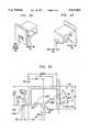
- FIGS. 1A and 1Bshow an illustrative prior art RJ-11 type plug
- FIG. 2shows a connector arrangement in accordance with the principles of the invention
- FIGS. 3A and 3Billustrate operation of the inventive concept
- FIGS. 4A and 4Bshow other illustrative views of an RJ-11 plug in accordance with the principles of the invention.
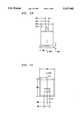
- FIGS. 5A through 5Eshow illustrative engineering drawings of an RJ-11 plug in accordance with the principles of the invention.
- FIGS. 1A and 1BA general representation of a prior art RJ-11 type plug, RJ-11 plug 10, is shown in FIGS. 1A and 1B for reference.
- FIG. 1Ais a side-view of the shape of RJ-11 plug 10.
- RJ-11 plug 10includes a release tab 12, locking tab 11, and shelf 14. The latter provides an offset that fits into a corresponding inset with an RJ-11 receptacle (not shown). This allows for proper seating to facilitate connection of any metallic contacts (not shown) within RJ-11 plug 10 to corresponding metallic contacts in the RJ-11 receptacle (not shown). Shelf 14 is solid and extends across most of the width of RJ-11 plug 10 as illustrated in FIG. 1B, which is a top-view of RJ-11 plug 10.
- RJ-11 receptacle 100is representative of a standard 6 position RJ-11 receptacle. For the purposes of this description, only a 6 position RJ-11 receptacle is described, however, the inventive concept easily extends to any size RJ-11 type receptacle irrespective of the number of positions within the RJ-11 type receptacle. In addition, whether RJ-11 receptacle 100 is wall-mounted or mounted within equipment is irrelevant to the inventive concept.
- RJ-11 plug 200comprises an outer shape 230, tang 220, locking tab 210, release tab 250, and faceplate 240.
- Outer shape 230conforms to the inside shape of RJ-11 receptacle 100. Molded to back edge 23 1 of outer shape 230 is illustrative tang 220. Outer shape 230 further includes locking tab 210, which is molded with back edge 231. Other than the inventive concept, locking tab 210 functions as in the prior art when plugged into receptacle 100.
- release tab 250is molded to locking tab 210 in such a way that it is contained within RJ-11 plug 200. The latter is covered by faceplate 240 which is molded to outer shape 230. Faceplate 240 includes tool access area 205, which is used to provide access to release tab 250.
- FIGS. 3A to 3Billustrate the inventive concept.
- RJ-11 plug 200is fully inserted into RJ-11 receptacle 100.
- locking tab 210is behind shelf 105, as known in the art.
- tang 220is also shown in FIG. 3A, and in accordance with the principles of the invention, which is compressed in the direction of back edge 231 as a result of the insertion of RJ-11 plug 200 into RJ-11 receptacle 100. This compression of tang 220 creates a positive pressure in the direction of, i.e., back towards, faceplate 240. (As noted above, RJ-11 200 is held in place by locking tab 210.)
- Locking tab 210is released by application of appropriate force on release tab 250. This is shown in FIG. 3B.
- Release tool 80e.g., a small screwdriver
- RJ-11 plug 200is no longer locked.
- the above-mentioned positive pressure exerted by tang 220pushes RJ-11 plug 200 out of RJ-11 receptacle 100 in the direction indicated by arrow 8.
- our designprovides an RJ-11 jack, or plug, that locks into position, must be tool operated to remove, and also has a user friendly self-ejecting feature for convenient removal.
- the self-ejecting mechanism described aboveis activated, as a result, by any pointed tool or thin object with a point, such as a pencil, being inserted into tool access area 205.
- this designprovides a convenient and easy to use RJ-11 plug for covering unused RJ-11 receptacles located on equipment.
- RJ-11 receptaclesFor example, often different versions of modem equipment are manufactured with one, two, or more, RJ-11 receptacles.
- a modem with one RJ-11 receptacleis called product "A”
- a modem with two RJ-11 receptaclesis called product "B.”
- these modemsmay be programmed differently to offer different features, the electrical components oftentimes are the same.
- product Ais only intended to use one RJ-11 receptacle a physically different housing is manufactured for product A than for product B, which has a housing to support two RJ-11 receptacles.
- the use of a different housing for product Aprovides a user of product A with only one choice of which RJ-11 receptacle to use. (If there were two open RJ-11 receptacles on product A, the user may inadvertently choose the wrong one).
- an RJ-11 plugin accordance with the principles of this invention allows one housing to be used--which can result in significant savings on a production line.
- the housing of product Bcan also be used for product A, with the unused RJ-11 receptacle conveniently blocked by an RJ-11 plug that is self-locking with tool operated and self ejecting features. This not only prevent a user of product A from using the wrong RJ-11 receptacle but also protects the equipment coupled to the metallic contacts of the unused RJ-11 receptacle from inadvertent shorts, etc.
- FIGS. 4A and 4Bshow two other isometric views of RJ-11 plug 200.
- FIGS. 5A through 5Eshow illustrative engineering drawings on the specifications of RJ-11 plug 200. All dimension techniques represented in FIGS. 5A through 5E are in accordance with ANSI standard Y14 dimensioning practice. In addition, the following terms, like “draft,” “gating,” “fillets,” etc., are known to one skilled in the art.
- the material used to manufacture RJ-11 plug 200is illustratively GE “Lexan” BE1130 (a polycarbonate) at a minimum thickness of 0.030 inches.
- the inside draft angleshould be 1 degree +/-one half of a degree.
- the outside draft angleis 3 degrees+/-one half of a degree.
- the inside fillets and radiusshould be 0.010 R.
- the outside fillets and radiusshould be 0.030 R. It is recommended that all textured surfaces have an SPI/SPE#3 or finer finish. Similarly, it is recommended that all weld and or knit lines should be minimized. All external dimensions affected by draft apply at the large end of the feature. All internal dimensions affected by draft apply at the small end of the feature. All comers shown sharp may be rounded to 0.010 R maximum. A gate is to be milled flush with emanating surface to +/-0.003 inches.
- the inventionis illustrated herein as being used to cover RJ-11 receptacles, it does not matter where the RJ-11 receptacle is mounted, whether this be in a wall, equipment, etc.
- the design of the tangmay vary as a function of the material used to manufacture the RJ-11 plug.
- the inventive conceptis applicable to other forms of telephone connectors.
Landscapes
- Details Of Connecting Devices For Male And Female Coupling (AREA)
Abstract
Description
Claims (17)
Priority Applications (2)
| Application Number | Priority Date | Filing Date | Title |
|---|---|---|---|
| US08/528,819US5637002A (en) | 1995-09-15 | 1995-09-15 | Self locking and ejecting RJ-11 plug |
| CA002209354ACA2209354A1 (en) | 1995-09-15 | 1997-06-30 | Self-locking and ejecting rf-11 plug |
Applications Claiming Priority (2)
| Application Number | Priority Date | Filing Date | Title |
|---|---|---|---|
| US08/528,819US5637002A (en) | 1995-09-15 | 1995-09-15 | Self locking and ejecting RJ-11 plug |
| CA002209354ACA2209354A1 (en) | 1995-09-15 | 1997-06-30 | Self-locking and ejecting rf-11 plug |
Publications (1)
| Publication Number | Publication Date |
|---|---|
| US5637002Atrue US5637002A (en) | 1997-06-10 |
Family
ID=25679460
Family Applications (1)
| Application Number | Title | Priority Date | Filing Date |
|---|---|---|---|
| US08/528,819Expired - LifetimeUS5637002A (en) | 1995-09-15 | 1995-09-15 | Self locking and ejecting RJ-11 plug |
Country Status (2)
| Country | Link |
|---|---|
| US (1) | US5637002A (en) |
| CA (1) | CA2209354A1 (en) |
Cited By (34)
| Publication number | Priority date | Publication date | Assignee | Title |
|---|---|---|---|---|
| USD399827S (en) | 1997-09-24 | 1998-10-20 | Gaffney David G | Dual RJ11 connector |
| USD411984S (en) | 1998-04-22 | 1999-07-13 | Peter Wu | Jack dust cover |
| EP1049210A1 (en)* | 1999-04-26 | 2000-11-02 | The Whitaker Corporation | Connector cover |
| US6309247B1 (en)* | 2000-08-08 | 2001-10-30 | Hon Hai Precision Ind. Co., Ltd. | Electrical connector having a dust-proof cover |
| US6454581B1 (en)* | 2000-12-28 | 2002-09-24 | Spx Corporation | Plug for covering a plurality of openings of an electronic device |
| US6595792B1 (en)* | 2000-10-30 | 2003-07-22 | Hewlett-Packard Development Company, L.P. | Tamper resistant plug for changing a function of an electronic device |
| US20040242038A1 (en)* | 2003-05-29 | 2004-12-02 | Gateway, Inc. | Self ejecting cover |
| US6835090B1 (en)* | 2002-12-13 | 2004-12-28 | Delta Systems, Inc. | Sealed housing assembly |
| WO2005053109A1 (en)* | 2003-11-26 | 2005-06-09 | Lintec Co., Ltd. | Dummy terminal |
| US20060040564A1 (en)* | 2004-08-19 | 2006-02-23 | Morrison David S | Block-out cover and removal tool |
| US7207813B1 (en)* | 2006-05-08 | 2007-04-24 | Primax Electronics Ltd. | Connector for coupling a data communication socket with a computer's peripheral device |
| FR2893454A1 (en)* | 2005-11-11 | 2007-05-18 | Infra & Sa | Low voltage connector`s e.g. RJ45 connector, socket opening protecting device for e.g. telephone, has snap-out hole plug including groove that engages with sliding shutter of socket opening, and closing plate with keyhole |
| CN100433469C (en)* | 2004-08-19 | 2008-11-12 | 泛达公司 | Block-out cover and removal tool |
| US20090007609A1 (en)* | 2007-07-03 | 2009-01-08 | Panduit Corp. | Plug Locking Assembly and System |
| US20090047818A1 (en)* | 2007-08-17 | 2009-02-19 | Panduit Corp. | Plug Locking Assembly |
| WO2009059269A1 (en) | 2007-11-02 | 2009-05-07 | The Siemon Company | Apparatus for plug-in and plug-out protection |
| CN100504741C (en)* | 2006-09-04 | 2009-06-24 | 致伸科技股份有限公司 | Connector with a locking member |
| US20100020550A1 (en)* | 2008-07-28 | 2010-01-28 | Panasonic Electric Works Co., Ltd. | Illumination device including a detachable sensor |
| WO2010097603A1 (en)* | 2009-02-26 | 2010-09-02 | Advanced Fiber Products Limited | Modular connector |
| US20100232756A1 (en)* | 2009-03-16 | 2010-09-16 | Panduit Corp. | Block-Out Device For Fiber Optic Adapter |
| WO2010125548A1 (en)* | 2009-04-28 | 2010-11-04 | Firecomms Limited | A connector |
| US20110097919A1 (en)* | 2009-10-23 | 2011-04-28 | Emcom Technology Inc. | Security Socket and Socket Device Having the Same |
| US20110194828A1 (en)* | 2010-02-05 | 2011-08-11 | Panduit Corp. | Block-Out Device for Fiber Optic Adapter |
| US20120282788A1 (en)* | 2011-05-06 | 2012-11-08 | Kuan-Lin Lin | Protective cover and removing tool therefor |
| US20160066455A1 (en)* | 2014-08-28 | 2016-03-03 | Wistron Corporation | Dustproof device |
| US9331426B2 (en) | 2009-02-26 | 2016-05-03 | Optical Fiber Packaging Corporation | Socket panel for receiving connector plugs with latch guards comprising a security cover plate |
| US20170105305A1 (en)* | 2015-10-08 | 2017-04-13 | Jacob Adams | Cable Assembly Management Elements and Fixture |
| CN108539453A (en)* | 2018-03-23 | 2018-09-14 | 烽火通信科技股份有限公司 | Protective cover method on protective cover, connector, extracting tool and dismantling connection device |
| US20200015374A1 (en)* | 2018-07-05 | 2020-01-09 | Comxi Co., Ltd. | Network port cover module and network port locking device having same |
| US20210281009A1 (en)* | 2015-03-27 | 2021-09-09 | CommScope Connectivity Spain, S.L. | Cover assembly for a telecommunications connector |
| USRE49007E1 (en) | 2010-03-01 | 2022-04-05 | Masimo Corporation | Adaptive alarm system |
| US11484205B2 (en) | 2002-03-25 | 2022-11-01 | Masimo Corporation | Physiological measurement device |
| US12057222B2 (en) | 2009-03-04 | 2024-08-06 | Masimo Corporation | Physiological alarm threshold determination |
| US12355196B2 (en) | 2015-03-27 | 2025-07-08 | CommScope Connectivity Spain, S.L. | Latch for telecommunications connector |
Citations (9)
| Publication number | Priority date | Publication date | Assignee | Title |
|---|---|---|---|---|
| US4526431A (en)* | 1983-02-14 | 1985-07-02 | Nec Corporation | Connector with mechanism for coupling and uncoupling plurality of blocks |
| US4615575A (en)* | 1985-04-29 | 1986-10-07 | Kossor Michael G | Modular connector for securing telephone line |
| US4681382A (en)* | 1985-12-20 | 1987-07-21 | Amp Incorporated | Electrical connector for transmission cable |
| US4975078A (en)* | 1989-12-15 | 1990-12-04 | Panduit Corp. | Modular telephone connector |
| US5044981A (en)* | 1990-04-18 | 1991-09-03 | Reliance Comm/Tec Corporation | Snap-on stacking telephone jack |
| US5061209A (en)* | 1991-03-13 | 1991-10-29 | Hubbell Incorporated | Wall plate jack and contact therefor |
| US5133668A (en)* | 1991-06-17 | 1992-07-28 | Brown Iv David C | Electrical connector apparatus |
| US5145416A (en)* | 1989-12-19 | 1992-09-08 | Adc Telecommunications, Inc. | Jack assembly |
| US5340333A (en)* | 1993-01-15 | 1994-08-23 | Interconnect Systems Group Inc. | Shielded modular adapter |
- 1995
- 1995-09-15USUS08/528,819patent/US5637002A/ennot_activeExpired - Lifetime
- 1997
- 1997-06-30CACA002209354Apatent/CA2209354A1/ennot_activeAbandoned
Patent Citations (9)
| Publication number | Priority date | Publication date | Assignee | Title |
|---|---|---|---|---|
| US4526431A (en)* | 1983-02-14 | 1985-07-02 | Nec Corporation | Connector with mechanism for coupling and uncoupling plurality of blocks |
| US4615575A (en)* | 1985-04-29 | 1986-10-07 | Kossor Michael G | Modular connector for securing telephone line |
| US4681382A (en)* | 1985-12-20 | 1987-07-21 | Amp Incorporated | Electrical connector for transmission cable |
| US4975078A (en)* | 1989-12-15 | 1990-12-04 | Panduit Corp. | Modular telephone connector |
| US5145416A (en)* | 1989-12-19 | 1992-09-08 | Adc Telecommunications, Inc. | Jack assembly |
| US5044981A (en)* | 1990-04-18 | 1991-09-03 | Reliance Comm/Tec Corporation | Snap-on stacking telephone jack |
| US5061209A (en)* | 1991-03-13 | 1991-10-29 | Hubbell Incorporated | Wall plate jack and contact therefor |
| US5133668A (en)* | 1991-06-17 | 1992-07-28 | Brown Iv David C | Electrical connector apparatus |
| US5340333A (en)* | 1993-01-15 | 1994-08-23 | Interconnect Systems Group Inc. | Shielded modular adapter |
Cited By (77)
| Publication number | Priority date | Publication date | Assignee | Title |
|---|---|---|---|---|
| USD399827S (en) | 1997-09-24 | 1998-10-20 | Gaffney David G | Dual RJ11 connector |
| USD411984S (en) | 1998-04-22 | 1999-07-13 | Peter Wu | Jack dust cover |
| EP1049210A1 (en)* | 1999-04-26 | 2000-11-02 | The Whitaker Corporation | Connector cover |
| SG90047A1 (en)* | 1999-04-26 | 2002-07-23 | Whitaker Corp | Connector cover |
| US6309247B1 (en)* | 2000-08-08 | 2001-10-30 | Hon Hai Precision Ind. Co., Ltd. | Electrical connector having a dust-proof cover |
| US6595792B1 (en)* | 2000-10-30 | 2003-07-22 | Hewlett-Packard Development Company, L.P. | Tamper resistant plug for changing a function of an electronic device |
| US20030211770A1 (en)* | 2000-10-30 | 2003-11-13 | Rudolph Daniel C. | Tamper resistant plug for changing a function of an electronic device |
| US6832926B2 (en) | 2000-10-30 | 2004-12-21 | Hewlett-Packard Development Company, L.P. | Tamper resistant plug for changing a function of an electronic device |
| US6454581B1 (en)* | 2000-12-28 | 2002-09-24 | Spx Corporation | Plug for covering a plurality of openings of an electronic device |
| US11484205B2 (en) | 2002-03-25 | 2022-11-01 | Masimo Corporation | Physiological measurement device |
| US6835090B1 (en)* | 2002-12-13 | 2004-12-28 | Delta Systems, Inc. | Sealed housing assembly |
| US20040242038A1 (en)* | 2003-05-29 | 2004-12-02 | Gateway, Inc. | Self ejecting cover |
| US6863550B2 (en) | 2003-05-29 | 2005-03-08 | Gateway, Inc. | Self ejecting cover |
| WO2005053109A1 (en)* | 2003-11-26 | 2005-06-09 | Lintec Co., Ltd. | Dummy terminal |
| US20070249195A1 (en)* | 2003-11-26 | 2007-10-25 | Lintec21 Co., Ltd. | Dummy Terminal |
| US20100130038A1 (en)* | 2003-11-26 | 2010-05-27 | Lintec21 Co., Ltd. | Dummy terminal |
| CN100433469C (en)* | 2004-08-19 | 2008-11-12 | 泛达公司 | Block-out cover and removal tool |
| US7722378B2 (en)* | 2004-08-19 | 2010-05-25 | Panduit Corp. | Block-out cover and removal tool |
| US20100229363A1 (en)* | 2004-08-19 | 2010-09-16 | Panduit Corp. | Block-Out Cover and Removal Tool |
| US7862365B2 (en) | 2004-08-19 | 2011-01-04 | Panduit Corp. | Block-out cover and removal tool |
| US8512061B2 (en) | 2004-08-19 | 2013-08-20 | Panduit Corp. | Block-out cover and removal tool |
| US20090088027A1 (en)* | 2004-08-19 | 2009-04-02 | Panduit Corp. | Block-Out Cover and Removal Tool |
| US8202110B2 (en) | 2004-08-19 | 2012-06-19 | Panduit Corp. | Block-out cover and removal tool |
| US20110065296A1 (en)* | 2004-08-19 | 2011-03-17 | Panduit Corp. | Block-Out Cover and Removal Tool |
| US8113856B2 (en) | 2004-08-19 | 2012-02-14 | Panduit Corp. | Block-out cover and removal tool |
| US8112879B2 (en) | 2004-08-19 | 2012-02-14 | Panduit Corp. | Method for removing a cover from a jack module |
| US20060040564A1 (en)* | 2004-08-19 | 2006-02-23 | Morrison David S | Block-out cover and removal tool |
| WO2006023788A1 (en)* | 2004-08-19 | 2006-03-02 | Panduit Corp. | Block-out cover and removal tool |
| US20100184313A1 (en)* | 2004-08-19 | 2010-07-22 | Panduit Corp. | Block-Out Cover and Removal Tool |
| FR2893454A1 (en)* | 2005-11-11 | 2007-05-18 | Infra & Sa | Low voltage connector`s e.g. RJ45 connector, socket opening protecting device for e.g. telephone, has snap-out hole plug including groove that engages with sliding shutter of socket opening, and closing plate with keyhole |
| US7207813B1 (en)* | 2006-05-08 | 2007-04-24 | Primax Electronics Ltd. | Connector for coupling a data communication socket with a computer's peripheral device |
| CN100504741C (en)* | 2006-09-04 | 2009-06-24 | 致伸科技股份有限公司 | Connector with a locking member |
| US7909625B2 (en) | 2007-07-03 | 2011-03-22 | Panduit Corp. | Plug locking assembly and system |
| US7806706B2 (en) | 2007-07-03 | 2010-10-05 | Panduit Corp. | Plug locking assembly and system |
| US20090007609A1 (en)* | 2007-07-03 | 2009-01-08 | Panduit Corp. | Plug Locking Assembly and System |
| US20100330832A1 (en)* | 2007-07-03 | 2010-12-30 | Panduit Corp. | Plug Locking Assembly and System |
| US20090047818A1 (en)* | 2007-08-17 | 2009-02-19 | Panduit Corp. | Plug Locking Assembly |
| US7632125B2 (en) | 2007-08-17 | 2009-12-15 | Panduit Corp. | Plug locking assembly |
| WO2009059269A1 (en) | 2007-11-02 | 2009-05-07 | The Siemon Company | Apparatus for plug-in and plug-out protection |
| EP2210314A4 (en)* | 2007-11-02 | 2012-05-16 | Siemon Co | Apparatus for plug-in and plug-out protection |
| US20100020550A1 (en)* | 2008-07-28 | 2010-01-28 | Panasonic Electric Works Co., Ltd. | Illumination device including a detachable sensor |
| US8167453B2 (en)* | 2008-07-28 | 2012-05-01 | Panasonic Corporation | Illumination device including interchangeable sensor and decoration members |
| CN104730648A (en)* | 2009-02-26 | 2015-06-24 | 先进光纤产品有限公司 | Fibre optic connector assembly and access tool kit |
| US8308498B2 (en) | 2009-02-26 | 2012-11-13 | Advanced Fiber Products Limited | Plug connector with latch guard and removal tools |
| CN102414933A (en)* | 2009-02-26 | 2012-04-11 | 先进光纤产品有限公司 | Modular connector |
| CN104730648B (en)* | 2009-02-26 | 2018-02-13 | 先进光纤产品有限公司 | Fiber light connector component and access tool bag |
| EP3148007A1 (en)* | 2009-02-26 | 2017-03-29 | Advanced Fiber Products Limited | Modular connector |
| CN106443892A (en)* | 2009-02-26 | 2017-02-22 | 先进光纤产品有限公司 | Modular connector |
| WO2010097603A1 (en)* | 2009-02-26 | 2010-09-02 | Advanced Fiber Products Limited | Modular connector |
| CN102414933B (en)* | 2009-02-26 | 2016-06-08 | 先进光纤产品有限公司 | Modular Connector |
| US9331426B2 (en) | 2009-02-26 | 2016-05-03 | Optical Fiber Packaging Corporation | Socket panel for receiving connector plugs with latch guards comprising a security cover plate |
| US8783968B2 (en) | 2009-02-26 | 2014-07-22 | Advanced Fiber Products, Limited | Fibre optic connector assembly and access tool kit |
| US12057222B2 (en) | 2009-03-04 | 2024-08-06 | Masimo Corporation | Physiological alarm threshold determination |
| US8277128B2 (en) | 2009-03-16 | 2012-10-02 | Panduit Corp. | Block-out device for fiber optic connector |
| CN101846775A (en)* | 2009-03-16 | 2010-09-29 | 泛达公司 | The locking device that is used for the fiber optics adapter |
| US20100232756A1 (en)* | 2009-03-16 | 2010-09-16 | Panduit Corp. | Block-Out Device For Fiber Optic Adapter |
| US7993063B2 (en) | 2009-03-16 | 2011-08-09 | Panduit Corp. | Block-out device for fiber optic adapter |
| WO2010125548A1 (en)* | 2009-04-28 | 2010-11-04 | Firecomms Limited | A connector |
| CN102460852A (en)* | 2009-04-28 | 2012-05-16 | 法尔科姆斯有限公司 | A connector |
| US7988478B2 (en)* | 2009-10-23 | 2011-08-02 | Emcom Technology Inc. | Security socket and socket device having the same |
| US20110097919A1 (en)* | 2009-10-23 | 2011-04-28 | Emcom Technology Inc. | Security Socket and Socket Device Having the Same |
| US20110194828A1 (en)* | 2010-02-05 | 2011-08-11 | Panduit Corp. | Block-Out Device for Fiber Optic Adapter |
| US8224146B2 (en) | 2010-02-05 | 2012-07-17 | Panduit Corp. | Block-out device for fiber optic adapter |
| USRE49007E1 (en) | 2010-03-01 | 2022-04-05 | Masimo Corporation | Adaptive alarm system |
| US20120282788A1 (en)* | 2011-05-06 | 2012-11-08 | Kuan-Lin Lin | Protective cover and removing tool therefor |
| US8323042B2 (en)* | 2011-05-06 | 2012-12-04 | Center Precision Co., Ltd. | Protective cover and removing tool therefor |
| US9345158B2 (en)* | 2014-08-28 | 2016-05-17 | Winstron Corporation | Dustproof device |
| US20160066455A1 (en)* | 2014-08-28 | 2016-03-03 | Wistron Corporation | Dustproof device |
| US12355196B2 (en) | 2015-03-27 | 2025-07-08 | CommScope Connectivity Spain, S.L. | Latch for telecommunications connector |
| US12206205B2 (en)* | 2015-03-27 | 2025-01-21 | CommScope Connectivity Spain, S.L. | Cover assembly for a telecommunications connector |
| US20210281009A1 (en)* | 2015-03-27 | 2021-09-09 | CommScope Connectivity Spain, S.L. | Cover assembly for a telecommunications connector |
| US20170105305A1 (en)* | 2015-10-08 | 2017-04-13 | Jacob Adams | Cable Assembly Management Elements and Fixture |
| US10098249B2 (en)* | 2015-10-08 | 2018-10-09 | Jacob Adams | Cable assembly management elements and fixture |
| CN108539453B (en)* | 2018-03-23 | 2020-06-16 | 烽火通信科技股份有限公司 | Protective cover, back plate assembly, dismounting tool and method for dismounting protective cover |
| CN108539453A (en)* | 2018-03-23 | 2018-09-14 | 烽火通信科技股份有限公司 | Protective cover method on protective cover, connector, extracting tool and dismantling connection device |
| US10624222B2 (en)* | 2018-07-05 | 2020-04-14 | Comxi Co., Ltd. | Network port cover module and network port locking device having same |
| US20200015374A1 (en)* | 2018-07-05 | 2020-01-09 | Comxi Co., Ltd. | Network port cover module and network port locking device having same |
Also Published As
| Publication number | Publication date |
|---|---|
| CA2209354A1 (en) | 1998-12-30 |
Similar Documents
| Publication | Publication Date | Title |
|---|---|---|
| US5637002A (en) | Self locking and ejecting RJ-11 plug | |
| US3942856A (en) | Safety socket assembly | |
| US6767228B2 (en) | Internal safety cover and method to prevent electrical shock | |
| US4311883A (en) | Modular telephone jack lock | |
| US6051788A (en) | Electrical outlet safety plate | |
| EP2165391B1 (en) | Plug locking assembly and system | |
| US5868261A (en) | Anti-slamming latch apparatus for modular component installations | |
| EP0305101B1 (en) | Connector system having combined latch and polerization member | |
| US5743752A (en) | Waterproof electrical connection apparatus | |
| US5971777A (en) | Breakaway physical/electrical media jack | |
| EP1544955A3 (en) | Socket for electrical connectors | |
| US5454731A (en) | Low profile electrical plug having plastic pull tab | |
| CN109921228A (en) | a plug-in component | |
| KR20010084128A (en) | Concentric plug | |
| US5340324A (en) | Phone jack lock | |
| CA2006506A1 (en) | Telephone lock | |
| CA2185982A1 (en) | Lock assembly with interchangeable key plug | |
| GB2366457A (en) | Electric socket outlet/plug cover | |
| JP3369080B2 (en) | Electronic equipment | |
| US5624270A (en) | Safety and/or polarizing devices of electric-power connectors | |
| US4666225A (en) | Electrical jack | |
| GB2187897A (en) | Enclosing electrical plug to prevent its use | |
| US4534586A (en) | Automatic locking device | |
| US6887088B2 (en) | Built-in device and system for masking an accessory, in particular an electrical connection and related electrical equipment | |
| JP4231729B2 (en) | Incorrect insertion prevention key and connector using the key |
Legal Events
| Date | Code | Title | Description |
|---|---|---|---|
| AS | Assignment | Owner name:AT&T PARADYNE CORP., FLORIDA Free format text:ASSIGNMENT OF ASSIGNORS INTEREST;ASSIGNORS:BUCK, CHARLES T.;STEFFEN, DENNIS L.;REEL/FRAME:007679/0315 Effective date:19950911 | |
| AS | Assignment | Owner name:PARADYNE CORPORATION (FORMERLY KNOWN AS AT&T PARAD Free format text:ASSIGNMENT OF ASSIGNORS INTEREST;ASSIGNOR:LUCENT TECHNOLOGIES, INC.;REEL/FRAME:008173/0166 Effective date:19960731 | |
| AS | Assignment | Owner name:PARADYNE CORPORATION, FLORIDA Free format text:CHANGE OF NAME;ASSIGNOR:AT&T PARADYNE CORP.;REEL/FRAME:008431/0544 Effective date:19960805 | |
| CC | Certificate of correction | ||
| FEPP | Fee payment procedure | Free format text:PAYOR NUMBER ASSIGNED (ORIGINAL EVENT CODE: ASPN); ENTITY STATUS OF PATENT OWNER: LARGE ENTITY | |
| FPAY | Fee payment | Year of fee payment:4 | |
| AS | Assignment | Owner name:FOOTHILL CAPITAL CORPORATION, CALIFORNIA Free format text:SECURITY AGREEMENT;ASSIGNOR:PARADYNE CORPORATION;REEL/FRAME:012211/0350 Effective date:20010716 | |
| REMI | Maintenance fee reminder mailed | ||
| AS | Assignment | Owner name:PARADYNE CORPORATION, FLORIDA Free format text:RELEASE OF SECURITY INTEREST;ASSIGNOR:WELLS FARGO FOOTHILL, INC. F/K/A FOOTHILL CAPITAL CORPORATION;REEL/FRAME:015603/0205 Effective date:20041216 | |
| REIN | Reinstatement after maintenance fee payment confirmed | ||
| FP | Lapsed due to failure to pay maintenance fee | Effective date:20050610 | |
| FEPP | Fee payment procedure | Free format text:PETITION RELATED TO MAINTENANCE FEES FILED (ORIGINAL EVENT CODE: PMFP); ENTITY STATUS OF PATENT OWNER: LARGE ENTITY | |
| AS | Assignment | Owner name:PIRIN POCKET DATA LLC, NEVADA Free format text:ASSIGNMENT OF ASSIGNORS INTEREST;ASSIGNOR:PARADYNE CORPORATION;REEL/FRAME:017297/0726 Effective date:20050202 | |
| FEPP | Fee payment procedure | Free format text:PETITION RELATED TO MAINTENANCE FEES GRANTED (ORIGINAL EVENT CODE: PMFG); ENTITY STATUS OF PATENT OWNER: LARGE ENTITY | |
| FPAY | Fee payment | Year of fee payment:8 | |
| SULP | Surcharge for late payment | ||
| PRDP | Patent reinstated due to the acceptance of a late maintenance fee | Effective date:20070619 | |
| STCF | Information on status: patent grant | Free format text:PATENTED CASE | |
| FPAY | Fee payment | Year of fee payment:12 | |
| FEPP | Fee payment procedure | Free format text:PAYER NUMBER DE-ASSIGNED (ORIGINAL EVENT CODE: RMPN); ENTITY STATUS OF PATENT OWNER: LARGE ENTITY Free format text:PAYOR NUMBER ASSIGNED (ORIGINAL EVENT CODE: ASPN); ENTITY STATUS OF PATENT OWNER: LARGE ENTITY |