US5636749A - Undulating screen for vibratory screening machine - Google Patents
Undulating screen for vibratory screening machineDownload PDFInfo
- Publication number
- US5636749A US5636749AUS08/443,856US44385695AUS5636749AUS 5636749 AUS5636749 AUS 5636749AUS 44385695 AUS44385695 AUS 44385695AUS 5636749 AUS5636749 AUS 5636749A
- Authority
- US
- United States
- Prior art keywords
- troughs
- ridges
- portions
- grid
- peaks
- Prior art date
- Legal status (The legal status is an assumption and is not a legal conclusion. Google has not performed a legal analysis and makes no representation as to the accuracy of the status listed.)
- Expired - Lifetime
Links
- 238000012216screeningMethods0.000titleclaimsabstractdescription34
- 239000004033plasticSubstances0.000claimsabstractdescription44
- 229920003023plasticPolymers0.000claimsabstractdescription44
- 230000037303wrinklesEffects0.000description11
- 239000004593EpoxySubstances0.000description10
- 238000010276constructionMethods0.000description4
- 239000002184metalSubstances0.000description4
- 238000000034methodMethods0.000description4
- 239000012466permeateSubstances0.000description4
- 230000000712assemblyEffects0.000description3
- 238000000429assemblyMethods0.000description3
- 239000000463materialSubstances0.000description3
- -1polyethylenePolymers0.000description3
- 239000004698PolyethyleneSubstances0.000description2
- 239000007788liquidSubstances0.000description2
- 229920000573polyethylenePolymers0.000description2
- XLYOFNOQVPJJNP-UHFFFAOYSA-NwaterSubstancesOXLYOFNOQVPJJNP-UHFFFAOYSA-N0.000description2
- 239000005995Aluminium silicateSubstances0.000description1
- 239000004743PolypropyleneSubstances0.000description1
- 229910000831SteelInorganic materials0.000description1
- 238000005299abrasionMethods0.000description1
- 238000009825accumulationMethods0.000description1
- 239000000853adhesiveSubstances0.000description1
- 230000001070adhesive effectEffects0.000description1
- 230000002411adverseEffects0.000description1
- 235000012211aluminium silicateNutrition0.000description1
- 230000009286beneficial effectEffects0.000description1
- 239000011230binding agentSubstances0.000description1
- 230000015572biosynthetic processEffects0.000description1
- 238000007598dipping methodMethods0.000description1
- 238000005553drillingMethods0.000description1
- NLYAJNPCOHFWQQ-UHFFFAOYSA-NkaolinChemical compoundO.O.O=[Al]O[Si](=O)O[Si](=O)O[Al]=ONLYAJNPCOHFWQQ-UHFFFAOYSA-N0.000description1
- 239000006194liquid suspensionSubstances0.000description1
- 229920001155polypropylenePolymers0.000description1
- 229920002635polyurethanePolymers0.000description1
- 239000004814polyurethaneSubstances0.000description1
- 238000004080punchingMethods0.000description1
- 239000002002slurrySubstances0.000description1
- 239000007787solidSubstances0.000description1
- 239000010959steelSubstances0.000description1
Images

Classifications
- B—PERFORMING OPERATIONS; TRANSPORTING
- B07—SEPARATING SOLIDS FROM SOLIDS; SORTING
- B07B—SEPARATING SOLIDS FROM SOLIDS BY SIEVING, SCREENING, SIFTING OR BY USING GAS CURRENTS; SEPARATING BY OTHER DRY METHODS APPLICABLE TO BULK MATERIAL, e.g. LOOSE ARTICLES FIT TO BE HANDLED LIKE BULK MATERIAL
- B07B1/00—Sieving, screening, sifting, or sorting solid materials using networks, gratings, grids, or the like
- B07B1/46—Constructional details of screens in general; Cleaning or heating of screens
- B07B1/4609—Constructional details of screens in general; Cleaning or heating of screens constructional details of screening surfaces or meshes
- B07B1/4654—Corrugated Screening surfaces
- B—PERFORMING OPERATIONS; TRANSPORTING
- B01—PHYSICAL OR CHEMICAL PROCESSES OR APPARATUS IN GENERAL
- B01D—SEPARATION
- B01D33/00—Filters with filtering elements which move during the filtering operation
- B01D33/01—Filters with filtering elements which move during the filtering operation with translationally moving filtering elements, e.g. pistons
- B01D33/03—Filters with filtering elements which move during the filtering operation with translationally moving filtering elements, e.g. pistons with vibrating filter elements
- B01D33/0346—Filters with filtering elements which move during the filtering operation with translationally moving filtering elements, e.g. pistons with vibrating filter elements with flat filtering elements
- B01D33/0376—Filters with filtering elements which move during the filtering operation with translationally moving filtering elements, e.g. pistons with vibrating filter elements with flat filtering elements supported
- B01D33/0384—Filters with filtering elements which move during the filtering operation with translationally moving filtering elements, e.g. pistons with vibrating filter elements with flat filtering elements supported with corrugated, folded or wound filtering sheets
- B—PERFORMING OPERATIONS; TRANSPORTING
- B01—PHYSICAL OR CHEMICAL PROCESSES OR APPARATUS IN GENERAL
- B01D—SEPARATION
- B01D33/00—Filters with filtering elements which move during the filtering operation
- B01D33/35—Filters with filtering elements which move during the filtering operation with multiple filtering elements characterised by their mutual disposition
- B01D33/41—Filters with filtering elements which move during the filtering operation with multiple filtering elements characterised by their mutual disposition in series connection
- B—PERFORMING OPERATIONS; TRANSPORTING
- B07—SEPARATING SOLIDS FROM SOLIDS; SORTING
- B07B—SEPARATING SOLIDS FROM SOLIDS BY SIEVING, SCREENING, SIFTING OR BY USING GAS CURRENTS; SEPARATING BY OTHER DRY METHODS APPLICABLE TO BULK MATERIAL, e.g. LOOSE ARTICLES FIT TO BE HANDLED LIKE BULK MATERIAL
- B07B1/00—Sieving, screening, sifting, or sorting solid materials using networks, gratings, grids, or the like
- B07B1/46—Constructional details of screens in general; Cleaning or heating of screens
- B07B1/4609—Constructional details of screens in general; Cleaning or heating of screens constructional details of screening surfaces or meshes
- B07B1/4663—Multi-layer screening surfaces
- B—PERFORMING OPERATIONS; TRANSPORTING
- B07—SEPARATING SOLIDS FROM SOLIDS; SORTING
- B07B—SEPARATING SOLIDS FROM SOLIDS BY SIEVING, SCREENING, SIFTING OR BY USING GAS CURRENTS; SEPARATING BY OTHER DRY METHODS APPLICABLE TO BULK MATERIAL, e.g. LOOSE ARTICLES FIT TO BE HANDLED LIKE BULK MATERIAL
- B07B1/00—Sieving, screening, sifting, or sorting solid materials using networks, gratings, grids, or the like
- B07B1/46—Constructional details of screens in general; Cleaning or heating of screens
- B07B1/4609—Constructional details of screens in general; Cleaning or heating of screens constructional details of screening surfaces or meshes
- B07B1/4672—Woven meshes
- B—PERFORMING OPERATIONS; TRANSPORTING
- B07—SEPARATING SOLIDS FROM SOLIDS; SORTING
- B07B—SEPARATING SOLIDS FROM SOLIDS BY SIEVING, SCREENING, SIFTING OR BY USING GAS CURRENTS; SEPARATING BY OTHER DRY METHODS APPLICABLE TO BULK MATERIAL, e.g. LOOSE ARTICLES FIT TO BE HANDLED LIKE BULK MATERIAL
- B07B1/00—Sieving, screening, sifting, or sorting solid materials using networks, gratings, grids, or the like
- B07B1/46—Constructional details of screens in general; Cleaning or heating of screens
- B07B1/4609—Constructional details of screens in general; Cleaning or heating of screens constructional details of screening surfaces or meshes
- B07B1/469—Perforated sheet-like material
- B—PERFORMING OPERATIONS; TRANSPORTING
- B01—PHYSICAL OR CHEMICAL PROCESSES OR APPARATUS IN GENERAL
- B01D—SEPARATION
- B01D2201/00—Details relating to filtering apparatus
- B01D2201/18—Filters characterised by the openings or pores
- B01D2201/188—Multiple filtering elements having filtering areas of different size
Definitions
- the present inventionrelates to an improved vibratory screen assembly for a vibratory screening machine, and more specifically to a vibratory screen assembly wherein a screen subassembly consisting of a plurality of screens of different mesh size are bonded to each other in an undulating shape without wrinkles by a fused plastic grid.
- Another object of the present inventionis to provide an improved screen assembly for a vibratory screening machine in which a plurality of screens which are bonded to each other by a fused plastic grid in an undulating configuration of ridges and troughs not only does not have wrinkles but also does not allow accumulation of material in the troughs.
- a further object of the present inventionis to provide an improved vibratory screen assembly having a multiple layer undulating screen subassembly of a fine screen bonded to a coarse screen which is conducive to relatively long life in that the fine screen does not have wrinkles which are subject to tearing due to flexing and abrasion when subjected to high G forces in operation.
- the present inventionrelates to a screening screen assembly for a vibratory screening machine comprising an apertured frame, an undulating subassembly of a support screen and a fine screening screen having ridges and troughs, a fused plastic grid bonding said fine screening screen to said support screen at spaced locations while leaving unobstructed portions of said screens therebetween, undersides on said troughs bonded to said apertured frame, said fused plastic grid including first portions extending substantially perpendicularly to the length dimension of said ridges and throughout the major portion of said sides of said ridges, and said fused plastic grid also including second portions which extend transversely of said first portions and extend through spaced portions of said troughs while leaving unobstructed portions of said troughs therebetween.
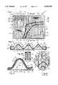
- FIG. 1is a fragmentary plan view of one embodiment of the improved screen assembly of the present invention with portions broken away to show various layers thereof;
- FIG. 2is a fragmentary enlarged cross sectional view taken substantially along line 2--2 of FIG. 1 and showing primarily the construction at the ends of the screen supporting plate for securing the vibratory screen in a vibratory screening machine;
- FIG. 3is a fragmentary cross sectional view taken substantially along line 3--3 of FIG. 1;
- FIG. 3Ais a fragmentary cross sectional view taken substantially along line 3A--3A of FIG. 1 and showing the seals at the ends of the ridges;
- FIG. 4is a fragmentary plan view of the undulating screen subassembly containing one type of fused plastic grid disclosed in U.S. Pat. No. 5,417,859;
- FIG. 4Ais a fragmentary plan view of a portion of FIG. 4;
- FIG. 4Bis a fragmentary cross-sectional view taken substantially along line 4B--4B of FIG. 4A;
- FIG. 4Cis a fragmentary cross-sectional view taken substantially along line 4C--4C of FIG. 4B;
- FIG. 5is a schematic view of the plastic grid configuration of FIG. 1;
- FIG. 6is a schematic plan view of another plastic grid configuration in accordance with the principles of the present invention.
- FIG. 7is a schematic plan view of still another plastic grid configuration in accordance with the principles of the present invention.
- the improved multi-layer undulating screen constructionis fabricated in such a configuration that it does not have wrinkles and is thus conducive to a longer life.
- FIGS. 1-3One embodiment of the improved screen assembly 10 is shown in FIGS. 1-3, and alternate configurations of plastic grids are shown in FIGS. 6 and 7.
- the improved screen assembly 10 of FIGS. 1-3includes a frame in the form of a perforated metal plate 11, such as steel or any other suitable metal, having a first pair of opposite edges 12 and 13 and a second pair of opposite edges 14 and 15 and an upper surface 16 and a lower surface 17.
- Plate 11includes apertures 19 which are bordered by elongated metal strip-like portions or members 20 which extend between edges 12 and 13 and by shorter strip-like portions 21 which extend lengthwise between elongated strip-like portions 20.
- the openings 19are formed by a punching operation and are quadrangles of approximately 1 inch square with rounded corners but they may be of any other desired shape or size.
- Strip-like portions 20 and 21are approximately 1/10 of an inch wide, but they may be of any desired width.
- the length of plate 11 between edges 12 and 13may be approximately 31/2 feet and its width between edges 14 and 15 may be approximately 21/2 feet, and it may have a thickness of about 1/16 of an inch. However, it will be appreciated that the size of plate 11 may vary as required to fit different machines.
- the width of each opening 19is a small fraction of the length of the plate between edges 12 and 13. The same is true of the relationship between the height of openings 19 and the width of the plate between edges 14 and 15.
- Channel-shaped members 22 and 23are mirror image counterparts and are constructed as shown in FIG. 2. More specifically, extensions 18 and 18' of plate 11 are folded into channel-shaped configurations. Sheet metal member 26 and 26', which are known as binders, are bent to the shape shown in FIG.
- plate 11is also essentially set forth in U.S. Pat. No. 4,575,421.
- any suitable plate or any suitable frame which provides the frame portions or members to which a screen can be attachedmay be utilized, and this may include a frame made of hollow rods or solid bars, and a frame of this type is disclosed in U.S. Pat. No. 5,417,858.
- the main feature of the embodiment of FIGS. 1-3is that the plurality of screens which are in an undulating shape of ridges and troughs and which are secured to plate 11 are bonded together into a subassembly by a perforated plastic grid 24 which has a specialized configuration and which has been fused into the screens 27, 29 and 30 by suitable heat and pressure in a specific orientation relative to the ridges and troughs.
- the screen subassembly 25includes a coarse screen 27 which serves a supporting function and may have a size of between 6 mesh and 20 mesh or any other suitable size.
- a fine screening screen 29is bonded to coarse supporting screen 27 and it may have a mesh size of between 30 mesh and 325 mesh, or any other suitable size.
- a finer screening screen 30is bonded to fine screening screen 29 and it may have a mesh size of between 40 mesh and 400 mesh, or any other suitable size.
- the intermediate fine screen 29should be two U.S. sieve sizes coarser than the finer uppermost screen 30.
- the three screens 27, 29 and 30are bonded to each other by a fused plastic grid 24 which permeates all three screens.
- the screen subassembly 25is formed in undulating curved shape, as depicted in FIGS. 2 and 3, and it has ridges 31 and troughs 32.
- the undersides of troughs 32 at 33are bonded to plate 11 by a suitable adhesive such as epoxy. This bonding at 33 occurs at all areas where the undersides of the troughs 32 contact strips 20 and 21.
- the open ends of the ridges 31are sealed or blocked by polyurethane caps 34 (FIG. 3A) which are molded into place as fully described in said U.S. Pat. No. 5,417,859, which is
- the screen subassembly 25consisting of bonded screens 27, 29 and 30 is formed in accordance with the method fully described in U.S. Pat. No. 5,417,859, which as noted above is incorporated herein by reference. Briefly, and by way of summary, screens 27, 29 and 30 and the plastic grid 24 are superimposed in contiguous abutting relationship, and suitable heat and pressure are applied to bond the foregoing parts into a unitary configuration wherein the plastic grid 24 fuses in a precisely controlled pattern and permeates the three screens 27, 29 and 30 and bonds them together, as can be seen from FIGS. 1 and 3.
- the plastic grid 24provides a gridwork within the screen assembly 25 wherein there are openings 44 (FIGS. 1 and 5) between the plastic portion 46 of the grid 24.
- a fragmentary plan view of the plastic grid 24is shown in FIGS. 1 and 5.
- the plastic grid 24is preferably made of polyethylene, and in this instance it was approximately 0.062 inches thick, that is, before it was fused by heat and pressure into bonding relationship with screens 27, 29 and 30. The bonding was effected by pressing the superimposed abutting screens 27, 29 and 30 and plastic grid 24 with a heated platen. The temperature of the platen was approximately 450° F. and it was applied at a pressure of 12 psi for approximately two minutes.
- the polyethylene grid 24should be fused to a sufficient degree so that it will permeate the openings in screens 27, 29 and 30 and bond them together. It will be appreciated that any other suitable plastic, such as polypropylene, which is heat-fusible may be used. It will also be appreciated that the bonding temperatures, pressures, and times of pressing will vary with the plastic, its thickness, the types of screens being bonded, and other factors. The foregoing is described in U.S. Pat. No. 5,417,859.
- the contacting portions of the screen subassembly 25 and plate 11are bonded to each other by epoxy, as mentioned above.
- this bondingis effected by dipping a heated perforated plate 11 into a fluidized powdered epoxy bed so that the powdered epoxy adheres to the plate.
- the plate with a layer of powdered epoxy thereonis then cooled. Thereafter, it is reheated to 350° F., and a suitable press (not shown) is used to hold the undersides of the troughs of the screen subassembly 25 in engagement with plate 11 for approximately three minutes and the epoxy will fuse into the undersides of the troughs of the screens.
- the undulating screenwill be bonded to the plate.
- the foregoing broad technique of bonding by the use of powdered epoxyis conventional in the art.
- the screen subassemblycan be adhesively secured to plate 11 by the use of liquid epoxy which is applied to the upper surface of the plate. It will be appreciated that any other suitable method of bonding the screen subassembly to the plate may be used.
- caps 34permeate the screen subassembly 25 and also provide a seal with the edge portions 162 and 163 (FIG. 3A) of edges 14 and 15, respectively.
- liquid epoxycan be used to produce caps 34.
- the ends of the ridgesmay be blocked by any other suitable method which may include but are not limited to those shown in copending patent application Ser. No. 08/062,464, now U.S. Pat. No. 5,417,858, which is incorporated herein by reference.
- the plastic grid 24(FIGS. 1 and 5) is in the form of hexagonal polygons 50 each having elongated sides 51 and shorter sides 52.
- the longer sides 51extend substantially perpendicularly across the peaks of the ridges 31 which are designated R and the shorter sides 52 criss-cross across the troughs 32, which are designated T.
- the portions 53 of elongated sides 51extend downwardly along the major portions of the sides 54 of the ridges 31.
- each hexagonal polygonal configuration of the grid 24has halves which are substantially symmetrical about the peaks R of the ridges 31 and which extend substantially perpendicularly to the peaks and downwardly along major portions of the sides 54 of the ridges 31.
- FIG. 4a prior construction is shown wherein an undulating multi-layered screen 60 is shown which has a coarse screen 61, a fine screen 62 and a finer screen 63 bonded to each other by a fused plastic grid 64.
- the multi-layer undulating screen 60is bonded to a perforated plate (not shown) such as 11.
- the polygonal shapes 65 of the fused plastic gridsare not symmetrical to the peaks R of the ridges 31, nor do the sides of these polygonal shapes extend substantially perpendicularly to the peaks R of the ridges.
- wrinkles 66which usually occur substantially parallel to the peaks R of the ridges and between relatively wide expanses of screen between the strips of the polygonal shapes.
- These wrinklesusually consist of elevated portions of the two upper screening screens as can be seen from FIGS. 4B and 4C. However, the wrinkle can also occur only in the uppermost screen. It will be appreciated that the wrinkles 66 exist primarily along the widest spacings between the fused plastic strips 67, but they can occur at other areas also. In any event, grid configurations which do not have the characteristics of the symmetrical grid configuration such as 24 are prone to having wrinkles at various spaced portions on either the uppermost screen or on both upper screens.
- FIG. 6another embodiment of a plastic grid 70 is disclosed.
- the grid 70functions in the same manner described above relative to the grid 24 to bond a plurality of screens into an undulating shape consisting of ridges and grooves.
- the grid 70is oriented so that the minor axis 75 of each ellipse-like configuration lies along the peak R of each ridge 31, and each side 73 not only extends substantially perpendicularly to the peak R of the ridge, such as 31, but also has substantially equal halves 77 on opposite sides of the peak R which is coextensive with the minor axis 75 of each ellipse-like configuration 72.
- each of the elongated sides 73 of adjacent rowsare connected to each other by plastic strips 79 which also lie along the peaks R of the ridges of the undulating shape.
- the curved ends 74 of adjacent ellipse-like configurations 71are fused to each other at 80 and these fused portions lie in the troughs T.
- there are spaces 81 between grid portions 80 along troughs Tso that there can be no puddling of material in the troughs 32.
- FIG. 7Another embodiment of a grid 85 is disclosed in FIG. 7 wherein it consists of a pattern of shapes 87 each of which has substantially straight sides 89 and curved ends 90.
- the straight sides 89extend substantially perpendicularly to the peaks R of the ridges and substantially equal portions of straight sides 89 lie on opposite sides of each peak R.
- the side Rextends through a major portion of the sides 54 of each ridge.
- the sides 90are part of a curved strip 91 which approximates a sinusoidal shape which criss-crosses across each trough T at points 92 so that portions 93 of each trough are unobstructed by the sinusoidal strip of plastic 91.
- the configurations 87include portions which extend substantially perpendicularly to the major portions of the ridges and include portions which are spaced along the troughs to leave portions of the troughs unobstructed.
- a screen which has been madehad the following dimensions:
- the plate 11had the dimensions set forth above relative to FIGS. 1-3.
- the base screen 27was 12 mesh
- the intermediate screen 29was 130 mesh
- the uppermost screen 30was 160 mesh.
- the undulating screenhad a dimension of 1.8 inches between cycles, that is 1.8 inches between adjacent crests and 1.8 inches between the bottoms of adjacent troughs.
- the radius at the bottoms of the troughswas 0.38 inches and the radius at the crests or peaks was 0.25 inches.
- the height of the ridges from plate 11 to the tops of the ridgeswas 0.8 inches. It will be appreciated that the curvature may be of any desired dimension which will provide the proper results.
- the screen assemblies described abovecan be utilized for dry screening, or can be utilized for wet screening of drilling mud which is a slurry of mud and water, and it can also be utilized for other liquid suspensions, such as kaolin and water.
- a machine of the type which performs a wet screening operationis disclosed in U.S. Pat. No. 4,882,054.
- the improved screen assembly 10 of the present inventionin addition to having all of the advantages enumerated above, also has all of the advantages of the screen assemblies disclosed in U.S. Pat. No. 5,417,859, which is incorporated herein by reference.
Landscapes
- Chemical & Material Sciences (AREA)
- Chemical Kinetics & Catalysis (AREA)
- Combined Means For Separation Of Solids (AREA)
Abstract
Description
The present invention relates to an improved vibratory screen assembly for a vibratory screening machine, and more specifically to a vibratory screen assembly wherein a screen subassembly consisting of a plurality of screens of different mesh size are bonded to each other in an undulating shape without wrinkles by a fused plastic grid.
In copending patent application Ser. No. 08/273,217, filed Jul. 11, 1994, now U.S. Pat. No. 5,417,859, various embodiments of vibratory screen assemblies are disclosed, each having a multi-screen undulating subassembly bonded to a perforated plate. Certain of the multi-screen undulating screen subassemblies comprise a plurality of screens of different mesh size bonded by a fused plastic grid. In copending application Ser. No. 08/443,377, filed May 17, 1996, which is a continuation of the aforementioned patent application Ser. No. 08/273,217, claims are presented to the configuration of certain embodiments of fused plastic grids which bond the plurality of screens in such a manner which does not produce wrinkles. The vibratory screen assembly of the present invention is an improvement over the subject matter of the foregoing applications.
It is one object of the present invention to provide an improved vibratory screen assembly wherein a multi-layer undulating screen is constructed in such a manner that one or more fine screens which are bonded to a coarse screen by a fused plastic grid will lie smoothly against the latter without wrinkles.
Another object of the present invention is to provide an improved screen assembly for a vibratory screening machine in which a plurality of screens which are bonded to each other by a fused plastic grid in an undulating configuration of ridges and troughs not only does not have wrinkles but also does not allow accumulation of material in the troughs.
A further object of the present invention is to provide an improved vibratory screen assembly having a multiple layer undulating screen subassembly of a fine screen bonded to a coarse screen which is conducive to relatively long life in that the fine screen does not have wrinkles which are subject to tearing due to flexing and abrasion when subjected to high G forces in operation. Other objects and attendant advantages of the present invention will readily be perceived hereafter.
The present invention relates to a screening screen assembly for a vibratory screening machine comprising an apertured frame, an undulating subassembly of a support screen and a fine screening screen having ridges and troughs, a fused plastic grid bonding said fine screening screen to said support screen at spaced locations while leaving unobstructed portions of said screens therebetween, undersides on said troughs bonded to said apertured frame, said fused plastic grid including first portions extending substantially perpendicularly to the length dimension of said ridges and throughout the major portion of said sides of said ridges, and said fused plastic grid also including second portions which extend transversely of said first portions and extend through spaced portions of said troughs while leaving unobstructed portions of said troughs therebetween.
The various aspects of the present invention will be more fully understood when the following portions of the specification are read in conjunction with the accompanying drawings wherein:
FIG. 1 is a fragmentary plan view of one embodiment of the improved screen assembly of the present invention with portions broken away to show various layers thereof;
FIG. 2 is a fragmentary enlarged cross sectional view taken substantially alongline 2--2 of FIG. 1 and showing primarily the construction at the ends of the screen supporting plate for securing the vibratory screen in a vibratory screening machine;
FIG. 3 is a fragmentary cross sectional view taken substantially alongline 3--3 of FIG. 1;
FIG. 3A is a fragmentary cross sectional view taken substantially alongline 3A--3A of FIG. 1 and showing the seals at the ends of the ridges;
FIG. 4 is a fragmentary plan view of the undulating screen subassembly containing one type of fused plastic grid disclosed in U.S. Pat. No. 5,417,859;
FIG. 4A is a fragmentary plan view of a portion of FIG. 4;
FIG. 4B is a fragmentary cross-sectional view taken substantially alongline 4B--4B of FIG. 4A;
FIG. 4C is a fragmentary cross-sectional view taken substantially alongline 4C--4C of FIG. 4B;
FIG. 5 is a schematic view of the plastic grid configuration of FIG. 1;
FIG. 6 is a schematic plan view of another plastic grid configuration in accordance with the principles of the present invention; and
FIG. 7 is a schematic plan view of still another plastic grid configuration in accordance with the principles of the present invention.
Summarizing briefly in advance, the improved multi-layer undulating screen construction is fabricated in such a configuration that it does not have wrinkles and is thus conducive to a longer life.
One embodiment of the improvedscreen assembly 10 is shown in FIGS. 1-3, and alternate configurations of plastic grids are shown in FIGS. 6 and 7.
The improvedscreen assembly 10 of FIGS. 1-3 includes a frame in the form of a perforated metal plate 11, such as steel or any other suitable metal, having a first pair ofopposite edges opposite edges upper surface 16 and alower surface 17. Plate 11 includesapertures 19 which are bordered by elongated metal strip-like portions ormembers 20 which extend betweenedges like portions 21 which extend lengthwise between elongated strip-like portions 20. Theopenings 19 are formed by a punching operation and are quadrangles of approximately 1 inch square with rounded corners but they may be of any other desired shape or size. Strip-like portions edges edges opening 19 is a small fraction of the length of the plate betweenedges openings 19 and the width of the plate betweenedges shaped members extensions 18 and 18' of plate 11 are folded into channel-shaped configurations.Sheet metal member 26 and 26', which are known as binders, are bent to the shape shown in FIG. 2 and they bracket theedges
The main feature of the embodiment of FIGS. 1-3 is that the plurality of screens which are in an undulating shape of ridges and troughs and which are secured to plate 11 are bonded together into a subassembly by a perforatedplastic grid 24 which has a specialized configuration and which has been fused into thescreens screen subassembly 25 includes acoarse screen 27 which serves a supporting function and may have a size of between 6 mesh and 20 mesh or any other suitable size. Afine screening screen 29 is bonded to coarse supportingscreen 27 and it may have a mesh size of between 30 mesh and 325 mesh, or any other suitable size. Afiner screening screen 30 is bonded tofine screening screen 29 and it may have a mesh size of between 40 mesh and 400 mesh, or any other suitable size. Preferably the intermediatefine screen 29 should be two U.S. sieve sizes coarser than the fineruppermost screen 30. The threescreens plastic grid 24 which permeates all three screens. Thescreen subassembly 25 is formed in undulating curved shape, as depicted in FIGS. 2 and 3, and it hasridges 31 andtroughs 32. The undersides oftroughs 32 at 33 are bonded to plate 11 by a suitable adhesive such as epoxy. This bonding at 33 occurs at all areas where the undersides of thetroughs 32 contact strips 20 and 21. The open ends of theridges 31 are sealed or blocked by polyurethane caps 34 (FIG. 3A) which are molded into place as fully described in said U.S. Pat. No. 5,417,859, which is incorporated herein by reference.
Thescreen subassembly 25 consisting of bondedscreens plastic grid 24 are superimposed in contiguous abutting relationship, and suitable heat and pressure are applied to bond the foregoing parts into a unitary configuration wherein theplastic grid 24 fuses in a precisely controlled pattern and permeates the threescreens
Theplastic grid 24 provides a gridwork within thescreen assembly 25 wherein there are openings 44 (FIGS. 1 and 5) between theplastic portion 46 of thegrid 24. A fragmentary plan view of theplastic grid 24 is shown in FIGS. 1 and 5. Theplastic grid 24 is preferably made of polyethylene, and in this instance it was approximately 0.062 inches thick, that is, before it was fused by heat and pressure into bonding relationship withscreens screens plastic grid 24 with a heated platen. The temperature of the platen was approximately 450° F. and it was applied at a pressure of 12 psi for approximately two minutes. The main consideration was that thepolyethylene grid 24 should be fused to a sufficient degree so that it will permeate the openings inscreens
After the screens were bonded to each other and they formed a planar laminate as shown in FIG. 8A, they were formed into the undulating shape shown in FIG. 3 by a suitable die arrangement as described in U.S. Pat. No. 5,417,859, which, as noted above, is incorporated herein by reference.
As noted in U.S. Pat. No. 5,417,859, plastic grids have been used in the past to bond screening screens together which were utilized in vibratory screening machines in a flat condition rather than in an undulating shape. Flat plastic bonded screens of this prior type did not function successfully in operation because the fused plastic grid permitted the screens to stretch when subjected to the high G forces encountered in operation. The reason that they stretched was that the entire width of the flat screens between their edges were unsupported. In contrast to the foregoing, the unsupported spans in the corrugated screen of the present invention is betweentroughs 32, and the stretching of the fused plastic is not a factor which adversely affects the operation. In fact, it is beneficial because it provides limited amounts of yieldability, as discussed above.
The contacting portions of thescreen subassembly 25 and plate 11 are bonded to each other by epoxy, as mentioned above. As described in U.S. Pat. No. 5,417,859, this bonding is effected by dipping a heated perforated plate 11 into a fluidized powdered epoxy bed so that the powdered epoxy adheres to the plate. The plate with a layer of powdered epoxy thereon is then cooled. Thereafter, it is reheated to 350° F., and a suitable press (not shown) is used to hold the undersides of the troughs of thescreen subassembly 25 in engagement with plate 11 for approximately three minutes and the epoxy will fuse into the undersides of the troughs of the screens. After the epoxy cools, the undulating screen will be bonded to the plate. The foregoing broad technique of bonding by the use of powdered epoxy is conventional in the art. if desired, the screen subassembly can be adhesively secured to plate 11 by the use of liquid epoxy which is applied to the upper surface of the plate. It will be appreciated that any other suitable method of bonding the screen subassembly to the plate may be used.
After the undulatingscreen subassembly 25 has been bonded to plate 11, the open ends of theridges 31 are sealed bycaps 34 as fully described in U.S. Pat. No. 5,417,859. It will be appreciated that caps 34 permeate thescreen subassembly 25 and also provide a seal with theedge portions 162 and 163 (FIG. 3A) ofedges caps 34. Also, the ends of the ridges may be blocked by any other suitable method which may include but are not limited to those shown in copending patent application Ser. No. 08/062,464, now U.S. Pat. No. 5,417,858, which is incorporated herein by reference.
In accordance with one embodiment of the present invention, the plastic grid 24 (FIGS. 1 and 5) is in the form ofhexagonal polygons 50 each having elongatedsides 51 andshorter sides 52. The longer sides 51 extend substantially perpendicularly across the peaks of theridges 31 which are designated R and theshorter sides 52 criss-cross across thetroughs 32, which are designated T. Theportions 53 ofelongated sides 51 extend downwardly along the major portions of thesides 54 of theridges 31. Theshort sides 52 of thehexagonal polygons 50 criss-cross acrosstroughs 32 to thereby provide open spaces in thetroughs 32 betweenpolygonal sides 52 which are unobstructed so that puddles of material being screened will not form along the troughs. It can thus be seen that each hexagonal polygonal configuration of thegrid 24 has halves which are substantially symmetrical about the peaks R of theridges 31 and which extend substantially perpendicularly to the peaks and downwardly along major portions of thesides 54 of theridges 31.
In FIG. 4 a prior construction is shown wherein an undulatingmulti-layered screen 60 is shown which has acoarse screen 61, afine screen 62 and afiner screen 63 bonded to each other by a fusedplastic grid 64. The multi-layer undulatingscreen 60 is bonded to a perforated plate (not shown) such as 11. As can be seen from FIG. 4, thepolygonal shapes 65 of the fused plastic grids are not symmetrical to the peaks R of theridges 31, nor do the sides of these polygonal shapes extend substantially perpendicularly to the peaks R of the ridges. This is conducive to the formation ofwrinkles 66 which usually occur substantially parallel to the peaks R of the ridges and between relatively wide expanses of screen between the strips of the polygonal shapes. These wrinkles usually consist of elevated portions of the two upper screening screens as can be seen from FIGS. 4B and 4C. However, the wrinkle can also occur only in the uppermost screen. It will be appreciated that thewrinkles 66 exist primarily along the widest spacings between the fused plastic strips 67, but they can occur at other areas also. In any event, grid configurations which do not have the characteristics of the symmetrical grid configuration such as 24 are prone to having wrinkles at various spaced portions on either the uppermost screen or on both upper screens.
In FIG. 6 another embodiment of aplastic grid 70 is disclosed. In this embodiment there arerows 71 of ellipse-like configurations 72 having opposed substantially straight sides 73 and rounded ends 74. Thegrid 70 functions in the same manner described above relative to thegrid 24 to bond a plurality of screens into an undulating shape consisting of ridges and grooves. Thegrid 70 is oriented so that theminor axis 75 of each ellipse-like configuration lies along the peak R of eachridge 31, and eachside 73 not only extends substantially perpendicularly to the peak R of the ridge, such as 31, but also has substantiallyequal halves 77 on opposite sides of the peak R which is coextensive with theminor axis 75 of each ellipse-like configuration 72. In addition, the midpoints of each of the elongated sides 73 of adjacent rows are connected to each other byplastic strips 79 which also lie along the peaks R of the ridges of the undulating shape. The curved ends 74 of adjacent ellipse-like configurations 71 are fused to each other at 80 and these fused portions lie in the troughs T. As can be seen from FIG. 6, there are spaces 81 betweengrid portions 80 along troughs T so that there can be no puddling of material in thetroughs 32.
Another embodiment of agrid 85 is disclosed in FIG. 7 wherein it consists of a pattern ofshapes 87 each of which has substantially straight sides 89 and curved ends 90. Thestraight sides 89 extend substantially perpendicularly to the peaks R of the ridges and substantially equal portions ofstraight sides 89 lie on opposite sides of each peak R. Furthermore, the side R extends through a major portion of thesides 54 of each ridge. Essentially thesides 90 are part of a curved strip 91 which approximates a sinusoidal shape which criss-crosses across each trough T at points 92 so thatportions 93 of each trough are unobstructed by the sinusoidal strip of plastic 91. Thus, theconfigurations 87 include portions which extend substantially perpendicularly to the major portions of the ridges and include portions which are spaced along the troughs to leave portions of the troughs unobstructed.
A screen which has been made had the following dimensions: The plate 11 had the dimensions set forth above relative to FIGS. 1-3. Thebase screen 27 was 12 mesh, theintermediate screen 29 was 130 mesh and theuppermost screen 30 was 160 mesh. The undulating screen had a dimension of 1.8 inches between cycles, that is 1.8 inches between adjacent crests and 1.8 inches between the bottoms of adjacent troughs. Also, the radius at the bottoms of the troughs was 0.38 inches and the radius at the crests or peaks was 0.25 inches. The height of the ridges from plate 11 to the tops of the ridges was 0.8 inches. It will be appreciated that the curvature may be of any desired dimension which will provide the proper results.
The screen assemblies described above can be utilized for dry screening, or can be utilized for wet screening of drilling mud which is a slurry of mud and water, and it can also be utilized for other liquid suspensions, such as kaolin and water. A machine of the type which performs a wet screening operation is disclosed in U.S. Pat. No. 4,882,054.
While the foregoing description has shown two fine screening screens bonded to a coarse screen, it will be appreciated that the wrinkle-free construction also is obtained when a single fine screen is bonded to a coarse supporting screen in the above-described manner.
Theimproved screen assembly 10 of the present invention, in addition to having all of the advantages enumerated above, also has all of the advantages of the screen assemblies disclosed in U.S. Pat. No. 5,417,859, which is incorporated herein by reference.
While preferred embodiments of the present invention have been disclosed, it will be appreciated that the present invention is not limited thereto but may be otherwise embodied within the scope of the following claims.
Claims (8)
1. A screening screen assembly for a vibratory screening machine comprising an apertured frame, an undulating subassembly of a support screen and a fine screening screen having ridges and troughs, peaks on said ridges, sides on said ridges between said peaks and said troughs, a fused plastic grid bonding said fine screening screen to said support screen at spaced locations while leaving unobstructed portions of said screens therebetween, undersides on said troughs bonded to said apertured frame, said fused plastic grid including first portions extending substantially perpendicularly to the length dimension of said ridges through said peaks and throughout the major portion of said sides of said ridges, and said fused plastic grid also including second portions which extend transversely of said first portions and extend through spaced portions of said troughs while leaving unobstructed portions of said troughs therebetween.
2. A screening screen assembly as set forth in claim 1 wherein said frame is a substantially planar apertured plate, and including means on said apertured plate for securing said apertured plate to the vibratory screening machine.
3. A screening screen assembly as set forth in claim 2 wherein said unobstructed portions of said grid have a substantially hexagonal configuration.
4. A screening screen assembly as set forth in claim 2 herein said unobstructed portions of said grid have a configuration of spaced rows of ellipse-like shapes with substantially straight sides and rounded ends with said substantially straight sides extending substantially perpendicularly to said ridges with the ellipse-like shapes of each row having their minor axes located substantially at the peak of each ridge and their rounded ends secured to each other substantially in said troughs on the opposite sides of each of said peaks, and said rows of ellipse-like shapes being connected to each other by strips which extend along said peaks of said ridges substantially between the midpoints of said sides of said ellipse-like shapes.
5. A screening screen assembly as set forth in claim 2 wherein said grid comprises spaced strips of plastic extending substantially perpendicularly across the peaks of said ridges toward said troughs and terminating at curved lines of plastic extending lengthwise of and crossing said troughs at spaced locations.
6. A screening screen assembly as set forth in claim 1 wherein said unobstructed portions of said grid have a substantially hexagonal configuration.
7. A screening screen assembly as set forth in claim 1 herein said unobstructed portions of said grid have a configuration of spaced rows of ellipse-like shapes with substantially straight sides and rounded ends with said substantially straight sides extending substantially perpendicularly to said ridges with the ellipse-like shapes of each row having their minor axes located substantially at the peak of each ridge and their rounded ends secured to each other substantially in said troughs on the opposite sides of each of said peaks, and said rows of ellipse-like shapes being connected to each other by strips which extend along said peaks of said ridges substantially between the midpoints of said sides of said ellipse-like shapes.
8. A screening screen assembly as set forth in claim 1 wherein said grid comprises spaced strips of plastic extending substantially perpendicularly across the peaks of said ridges toward said troughs and terminating at curved lines of plastic extending lengthwise of and crossing said troughs at spaced locations.
Priority Applications (1)
| Application Number | Priority Date | Filing Date | Title |
|---|---|---|---|
| US08/443,856US5636749A (en) | 1995-05-18 | 1995-05-18 | Undulating screen for vibratory screening machine |
Applications Claiming Priority (1)
| Application Number | Priority Date | Filing Date | Title |
|---|---|---|---|
| US08/443,856US5636749A (en) | 1995-05-18 | 1995-05-18 | Undulating screen for vibratory screening machine |
Publications (1)
| Publication Number | Publication Date |
|---|---|
| US5636749Atrue US5636749A (en) | 1997-06-10 |
Family
ID=23762458
Family Applications (1)
| Application Number | Title | Priority Date | Filing Date |
|---|---|---|---|
| US08/443,856Expired - LifetimeUS5636749A (en) | 1995-05-18 | 1995-05-18 | Undulating screen for vibratory screening machine |
Country Status (1)
| Country | Link |
|---|---|
| US (1) | US5636749A (en) |
Cited By (66)
| Publication number | Priority date | Publication date | Assignee | Title |
|---|---|---|---|---|
| US5744036A (en)* | 1997-02-03 | 1998-04-28 | Aaf International | Pleated filter arrangement |
| US5967336A (en)* | 1997-09-02 | 1999-10-19 | Southwestern Wire Cloth, Inc. | Vibrating screen assembly with improved frame |
| US5971159A (en) | 1993-04-30 | 1999-10-26 | Tuboscope I/P, Inc. | Screen assembly for a vibratory separator |
| US6000556A (en)* | 1993-01-13 | 1999-12-14 | Derrick Manufacturing Corporation | Screen assembly for vibratory screening machine |
| US6029824A (en)* | 1994-03-30 | 2000-02-29 | Tuboscope I/P, Inc. | Screen for vibrating separator |
| US6053331A (en)* | 1998-11-17 | 2000-04-25 | Cravello; William M. | Non-tensioned shaker filter |
| USD425531S (en)* | 1999-03-29 | 2000-05-23 | Tuboscope I/P, Inc. | Screen |
| US6152307A (en) | 1993-04-30 | 2000-11-28 | Tuboscope I/P, Inc. | Vibratory separator screens |
| US6186337B1 (en)* | 1998-10-30 | 2001-02-13 | Tuboscope I/P, Inc. | Dual screen element having upper scalping screen adhered to crests of corrugated lower screen |
| WO2001017659A1 (en)* | 1999-09-03 | 2001-03-15 | Varco I/P, Inc. | A screen assembly for a vibratory shaker |
| US6202856B1 (en)* | 1999-09-22 | 2001-03-20 | Emerson Electric Co. | Vibratory screening system and screen therefor |
| US6220449B1 (en) | 1999-10-01 | 2001-04-24 | Tuboscope I/P, Inc. | Flat top cloth support screen |
| US6241098B1 (en) | 1999-06-24 | 2001-06-05 | Tubo Scope I/P, Inc. | Drilling fluid treatment operations and apparatuses |
| US6267247B1 (en) | 1993-04-30 | 2001-07-31 | Tuboscope I/P, Inc. | Vibratory separator screen |
| US6269953B1 (en) | 1993-04-30 | 2001-08-07 | Tuboscope I/P, Inc. | Vibratory separator screen assemblies |
| US6283302B1 (en) | 1993-08-12 | 2001-09-04 | Tuboscope I/P, Inc. | Unibody screen structure |
| US6290068B1 (en) | 1993-04-30 | 2001-09-18 | Tuboscope I/P, Inc. | Shaker screens and methods of use |
| US6305549B1 (en) | 1999-07-06 | 2001-10-23 | Southwestern Wire Cloth, Inc. | Vibrating screen assembly of dissimilar materials |
| US20020027102A1 (en)* | 2000-07-13 | 2002-03-07 | Robillard Norman F. | Filter cartridges with pleated filter media |
| US6371301B1 (en) | 2000-11-17 | 2002-04-16 | Varco I/P, Inc. | Screen basket for shale shakers |
| US6371302B1 (en) | 1993-04-30 | 2002-04-16 | Tuboscope I/P, Inc. | Vibratory separator screens |
| US6401934B1 (en) | 1993-04-30 | 2002-06-11 | Tuboscope I/P, Inc. | Ramped screen & vibratory separator system |
| US6439392B1 (en) | 1997-09-02 | 2002-08-27 | Southwestern Wire Cloth, Inc. | Vibrating screen assembly with tubular frame |
| US6443310B1 (en) | 1993-04-30 | 2002-09-03 | Varco I/P, Inc. | Seal screen structure |
| US6450345B1 (en) | 1993-04-30 | 2002-09-17 | Varco I/P, Inc. | Glue pattern screens and methods of production |
| US6454099B1 (en) | 1993-04-30 | 2002-09-24 | Varco I/P, Inc | Vibrator separator screens |
| US20030010437A1 (en)* | 1998-10-30 | 2003-01-16 | Adams Thomas C. | Screens for vibratory separators |
| US6565698B1 (en) | 1993-04-30 | 2003-05-20 | Varco I/P, Inc. | Method for making vibratory separator screens |
| US6581781B1 (en) | 1993-04-30 | 2003-06-24 | Tuboscope I/P, Inc. | Vibrator separator screens |
| US6607080B2 (en) | 1993-04-30 | 2003-08-19 | Varco I/P, Inc. | Screen assembly for vibratory separators |
| US6629610B1 (en) | 1993-04-30 | 2003-10-07 | Tuboscope I/P, Inc. | Screen with ramps for vibratory separator system |
| US20030222032A1 (en)* | 2002-05-29 | 2003-12-04 | Rudiger Tueshaus | Filtering screen construction and methods |
| US6669985B2 (en) | 1998-10-30 | 2003-12-30 | Varco I/P, Inc. | Methods for making glued shale shaker screens |
| US20040007508A1 (en)* | 1999-12-04 | 2004-01-15 | Schulte David L. | Screen assembly for vibratory separator |
| US6722504B2 (en) | 1993-04-30 | 2004-04-20 | Varco I/P, Inc. | Vibratory separators and screens |
| US20040074817A1 (en)* | 1998-10-30 | 2004-04-22 | Adams Thomas C. | Vibratory separator screens |
| US6736270B2 (en) | 1998-10-30 | 2004-05-18 | Varco I/P, Inc. | Glued screens for shale shakers |
| US20040251175A1 (en)* | 1998-10-30 | 2004-12-16 | Adams Thomas C. | Apparatuses and methods for making glued screen assemblies |
| US20050000865A1 (en)* | 1998-10-30 | 2005-01-06 | Schulte David L. | Screen assemblies and vibratory separators |
| US20050016674A1 (en)* | 2003-07-25 | 2005-01-27 | Ward Kerry T. | Methods for making screen assemblies |
| US20050056570A1 (en)* | 2003-08-29 | 2005-03-17 | Colgrove James R. | Vibratory screen assemblies |
| US20050103689A1 (en)* | 2001-10-19 | 2005-05-19 | Schulte David L.Jr. | Sealing screen assemblies and vibratory separators |
| US20050199532A1 (en)* | 2000-11-17 | 2005-09-15 | Schulte David L. | Screen basket and shale shakers |
| US20050224398A1 (en)* | 2001-10-19 | 2005-10-13 | Largent David W | Vibratory separators and sealing screens |
| US20050274655A1 (en)* | 2004-06-15 | 2005-12-15 | Barrett Robert M | Screen assembly designed to conform to the radius of vibrating shakers with crowned decks |
| US20060011520A1 (en)* | 2000-11-17 | 2006-01-19 | Schulte David L | Dam basket for vibratory separators |
| US20060163122A1 (en)* | 2005-01-21 | 2006-07-27 | Bakula John J | Vibratory material screen with seal |
| US20070125688A1 (en)* | 2005-12-06 | 2007-06-07 | Rotex, Inc. | Screening machine, associated screen panel and seal |
| US20080223761A1 (en)* | 2007-03-14 | 2008-09-18 | Rotex, Inc. | Sealing Mechanism and Associated Sealing Method for Screening Machines |
| US20090060955A1 (en)* | 2007-08-31 | 2009-03-05 | You Han Bae | Drug delivery vehicle that mimics viral properties |
| US20090071561A1 (en)* | 2007-09-12 | 2009-03-19 | Dennis Dalrymple | Method and system for improving gas flow in a duct or pipe |
| US20090145816A1 (en)* | 2007-12-11 | 2009-06-11 | Paul William Dufilho | Screen assemblies for shale shakers |
| US20090230029A1 (en)* | 2005-12-06 | 2009-09-17 | Rotex Global, Llc | Screening machine and associated screen panel |
| US20100258484A1 (en)* | 2009-04-13 | 2010-10-14 | Helmy Nashat N | Sifting screen |
| US20100283241A1 (en)* | 2007-03-28 | 2010-11-11 | Varco I/P, Inc. | Clamp Apparatus for Threadedly Connected Tubulars |
| US20110036759A1 (en)* | 2005-12-06 | 2011-02-17 | Rotex, Inc. | Screening machine and associated screen panel |
| US7980392B2 (en) | 2007-08-31 | 2011-07-19 | Varco I/P | Shale shaker screens with aligned wires |
| US8533974B2 (en) | 2006-10-04 | 2013-09-17 | Varco I/P, Inc. | Reclamation of components of wellbore cuttings material |
| US8561805B2 (en) | 2002-11-06 | 2013-10-22 | National Oilwell Varco, L.P. | Automatic vibratory separator |
| US8622220B2 (en) | 2007-08-31 | 2014-01-07 | Varco I/P | Vibratory separators and screens |
| US8695805B2 (en) | 2002-11-06 | 2014-04-15 | National Oilwell Varco, L.P. | Magnetic vibratory screen clamping |
| US20160059162A1 (en)* | 2013-04-30 | 2016-03-03 | M-I Drilling Fluids Uk Ltd. | Screen having frame members with angled surface(s) |
| US9643111B2 (en) | 2013-03-08 | 2017-05-09 | National Oilwell Varco, L.P. | Vector maximizing screen |
| US9677353B2 (en) | 2008-10-10 | 2017-06-13 | National Oilwell Varco, L.P. | Shale shakers with selective series/parallel flow path conversion |
| CN112264284A (en)* | 2020-11-04 | 2021-01-26 | 常州苏盛塑粉制造有限公司 | Filtering and screening device for plastic powder |
| US10953353B2 (en) | 2015-07-24 | 2021-03-23 | Schlumberger Technology Corporation | Perforated foil screen assembly |
Citations (3)
| Publication number | Priority date | Publication date | Assignee | Title |
|---|---|---|---|---|
| CA599661A (en)* | 1960-06-14 | H. Eaton-Williams Raymond | Fluid filters formed of fabrics containing thermoplastic yarns | |
| US5417859A (en)* | 1993-01-13 | 1995-05-23 | Derrick Manufacturing Corporation | Undulating screen for vibratory screening machine and method of fabrication thereof |
| US5417858A (en)* | 1993-01-13 | 1995-05-23 | Derrick Manufacturing Corporation | Screen assembly for vibrating screening machine |
- 1995
- 1995-05-18USUS08/443,856patent/US5636749A/ennot_activeExpired - Lifetime
Patent Citations (4)
| Publication number | Priority date | Publication date | Assignee | Title |
|---|---|---|---|---|
| CA599661A (en)* | 1960-06-14 | H. Eaton-Williams Raymond | Fluid filters formed of fabrics containing thermoplastic yarns | |
| US5417859A (en)* | 1993-01-13 | 1995-05-23 | Derrick Manufacturing Corporation | Undulating screen for vibratory screening machine and method of fabrication thereof |
| US5417858A (en)* | 1993-01-13 | 1995-05-23 | Derrick Manufacturing Corporation | Screen assembly for vibrating screening machine |
| US5417793A (en)* | 1993-01-13 | 1995-05-23 | Derrick Manufacturing Corporation | Undulating screen for vibratory screening machine and method of fabrication thereof |
Cited By (96)
| Publication number | Priority date | Publication date | Assignee | Title |
|---|---|---|---|---|
| US6000556A (en)* | 1993-01-13 | 1999-12-14 | Derrick Manufacturing Corporation | Screen assembly for vibratory screening machine |
| US6607080B2 (en) | 1993-04-30 | 2003-08-19 | Varco I/P, Inc. | Screen assembly for vibratory separators |
| US6302276B1 (en) | 1993-04-30 | 2001-10-16 | Tuboscope I/P, Inc. | Screen support strip for use in vibratory screening apparatus |
| US6371302B1 (en) | 1993-04-30 | 2002-04-16 | Tuboscope I/P, Inc. | Vibratory separator screens |
| US20050236305A1 (en)* | 1993-04-30 | 2005-10-27 | Schulte David L Jr | Vibratory separators and screens for them |
| US6443310B1 (en) | 1993-04-30 | 2002-09-03 | Varco I/P, Inc. | Seal screen structure |
| US6032806A (en) | 1993-04-30 | 2000-03-07 | Tuboscope I/P, Inc. | Screen apparatus for vibratory separator |
| US6892888B2 (en) | 1993-04-30 | 2005-05-17 | Varco I/P, Inc. | Screen with unibody structure |
| US6450345B1 (en) | 1993-04-30 | 2002-09-17 | Varco I/P, Inc. | Glue pattern screens and methods of production |
| US6152307A (en) | 1993-04-30 | 2000-11-28 | Tuboscope I/P, Inc. | Vibratory separator screens |
| US6722504B2 (en) | 1993-04-30 | 2004-04-20 | Varco I/P, Inc. | Vibratory separators and screens |
| US6629610B1 (en) | 1993-04-30 | 2003-10-07 | Tuboscope I/P, Inc. | Screen with ramps for vibratory separator system |
| US6401934B1 (en) | 1993-04-30 | 2002-06-11 | Tuboscope I/P, Inc. | Ramped screen & vibratory separator system |
| US5971159A (en) | 1993-04-30 | 1999-10-26 | Tuboscope I/P, Inc. | Screen assembly for a vibratory separator |
| US6325216B1 (en) | 1993-04-30 | 2001-12-04 | Tuboscope I/P, Inc. | Screen apparatus for vibratory separator |
| US6581781B1 (en) | 1993-04-30 | 2003-06-24 | Tuboscope I/P, Inc. | Vibrator separator screens |
| US6530483B2 (en) | 1993-04-30 | 2003-03-11 | Varco I/P, Inc. | Unibody structure for screen assembly |
| US6269953B1 (en) | 1993-04-30 | 2001-08-07 | Tuboscope I/P, Inc. | Vibratory separator screen assemblies |
| US6565698B1 (en) | 1993-04-30 | 2003-05-20 | Varco I/P, Inc. | Method for making vibratory separator screens |
| US6290068B1 (en) | 1993-04-30 | 2001-09-18 | Tuboscope I/P, Inc. | Shaker screens and methods of use |
| US6267247B1 (en) | 1993-04-30 | 2001-07-31 | Tuboscope I/P, Inc. | Vibratory separator screen |
| US6454099B1 (en) | 1993-04-30 | 2002-09-24 | Varco I/P, Inc | Vibrator separator screens |
| US6283302B1 (en) | 1993-08-12 | 2001-09-04 | Tuboscope I/P, Inc. | Unibody screen structure |
| US6029824A (en)* | 1994-03-30 | 2000-02-29 | Tuboscope I/P, Inc. | Screen for vibrating separator |
| US5988397A (en) | 1996-02-12 | 1999-11-23 | Tuboscope I/P, Inc. | Screen for vibratory separator |
| US5744036A (en)* | 1997-02-03 | 1998-04-28 | Aaf International | Pleated filter arrangement |
| US6269954B1 (en) | 1997-09-02 | 2001-08-07 | Southwestern Wire Cloth, Inc. | Seal for adjoining screen assemblies in vibrating machinery |
| US6439392B1 (en) | 1997-09-02 | 2002-08-27 | Southwestern Wire Cloth, Inc. | Vibrating screen assembly with tubular frame |
| US5967336A (en)* | 1997-09-02 | 1999-10-19 | Southwestern Wire Cloth, Inc. | Vibrating screen assembly with improved frame |
| US6669985B2 (en) | 1998-10-30 | 2003-12-30 | Varco I/P, Inc. | Methods for making glued shale shaker screens |
| US7000777B2 (en)* | 1998-10-30 | 2006-02-21 | Varco I/P, Inc. | Vibratory separator screens |
| US6932883B2 (en) | 1998-10-30 | 2005-08-23 | Varco I/P, Inc. | Screens for vibratory separators |
| US20030010437A1 (en)* | 1998-10-30 | 2003-01-16 | Adams Thomas C. | Screens for vibratory separators |
| US20050000865A1 (en)* | 1998-10-30 | 2005-01-06 | Schulte David L. | Screen assemblies and vibratory separators |
| US20040251175A1 (en)* | 1998-10-30 | 2004-12-16 | Adams Thomas C. | Apparatuses and methods for making glued screen assemblies |
| US6736270B2 (en) | 1998-10-30 | 2004-05-18 | Varco I/P, Inc. | Glued screens for shale shakers |
| US20040074817A1 (en)* | 1998-10-30 | 2004-04-22 | Adams Thomas C. | Vibratory separator screens |
| US6186337B1 (en)* | 1998-10-30 | 2001-02-13 | Tuboscope I/P, Inc. | Dual screen element having upper scalping screen adhered to crests of corrugated lower screen |
| US6053331A (en)* | 1998-11-17 | 2000-04-25 | Cravello; William M. | Non-tensioned shaker filter |
| USD425531S (en)* | 1999-03-29 | 2000-05-23 | Tuboscope I/P, Inc. | Screen |
| US6241098B1 (en) | 1999-06-24 | 2001-06-05 | Tubo Scope I/P, Inc. | Drilling fluid treatment operations and apparatuses |
| US6305549B1 (en) | 1999-07-06 | 2001-10-23 | Southwestern Wire Cloth, Inc. | Vibrating screen assembly of dissimilar materials |
| WO2001017659A1 (en)* | 1999-09-03 | 2001-03-15 | Varco I/P, Inc. | A screen assembly for a vibratory shaker |
| US6202856B1 (en)* | 1999-09-22 | 2001-03-20 | Emerson Electric Co. | Vibratory screening system and screen therefor |
| US6220449B1 (en) | 1999-10-01 | 2001-04-24 | Tuboscope I/P, Inc. | Flat top cloth support screen |
| US20040007508A1 (en)* | 1999-12-04 | 2004-01-15 | Schulte David L. | Screen assembly for vibratory separator |
| US7520391B2 (en) | 1999-12-04 | 2009-04-21 | Varco I/P, Inc. | Screen assembly for vibratory separator |
| US20020027102A1 (en)* | 2000-07-13 | 2002-03-07 | Robillard Norman F. | Filter cartridges with pleated filter media |
| US20050199532A1 (en)* | 2000-11-17 | 2005-09-15 | Schulte David L. | Screen basket and shale shakers |
| US7198156B2 (en) | 2000-11-17 | 2007-04-03 | Varco I/P, Inc. | Dam basket for vibratory separators |
| US7216767B2 (en) | 2000-11-17 | 2007-05-15 | Varco I/P, Inc. | Screen basket and shale shakers |
| US6412644B1 (en) | 2000-11-17 | 2002-07-02 | Varco I/P, Inc. | Vibratory separator |
| US6371301B1 (en) | 2000-11-17 | 2002-04-16 | Varco I/P, Inc. | Screen basket for shale shakers |
| US6863183B2 (en) | 2000-11-17 | 2005-03-08 | Varco I/P, Inc. | Shale shaker |
| US20060011520A1 (en)* | 2000-11-17 | 2006-01-19 | Schulte David L | Dam basket for vibratory separators |
| US6715611B2 (en) | 2000-11-17 | 2004-04-06 | Tuboscope I/P, Inc. | Vibratory separator |
| US20050224398A1 (en)* | 2001-10-19 | 2005-10-13 | Largent David W | Vibratory separators and sealing screens |
| US20050103689A1 (en)* | 2001-10-19 | 2005-05-19 | Schulte David L.Jr. | Sealing screen assemblies and vibratory separators |
| US20060000786A1 (en)* | 2002-05-29 | 2006-01-05 | Ruediger Tueshaus | Filtering screen construction and methods |
| US20030222032A1 (en)* | 2002-05-29 | 2003-12-04 | Rudiger Tueshaus | Filtering screen construction and methods |
| US8695805B2 (en) | 2002-11-06 | 2014-04-15 | National Oilwell Varco, L.P. | Magnetic vibratory screen clamping |
| US8561805B2 (en) | 2002-11-06 | 2013-10-22 | National Oilwell Varco, L.P. | Automatic vibratory separator |
| US20050016674A1 (en)* | 2003-07-25 | 2005-01-27 | Ward Kerry T. | Methods for making screen assemblies |
| US7094297B2 (en)* | 2003-07-25 | 2006-08-22 | Yanco I/P, Inc. | Methods for making screen assemblies |
| US20050056570A1 (en)* | 2003-08-29 | 2005-03-17 | Colgrove James R. | Vibratory screen assemblies |
| US7175028B2 (en)* | 2003-08-29 | 2007-02-13 | Derrick Corporation | Vibratory screen assemblies |
| US7011218B2 (en)* | 2003-08-29 | 2006-03-14 | Derrick Corporation | Vibratory screen assemblies |
| US20050056571A1 (en)* | 2003-08-29 | 2005-03-17 | Derrick Manufacturing Corporation | Vibratory screen assemblies |
| US7757864B2 (en) | 2004-06-15 | 2010-07-20 | M-I L.L.C. | Screen assembly designed to conform to the radius of vibrating shakers with crowned decks |
| US20050274655A1 (en)* | 2004-06-15 | 2005-12-15 | Barrett Robert M | Screen assembly designed to conform to the radius of vibrating shakers with crowned decks |
| US8312996B2 (en) | 2005-01-21 | 2012-11-20 | Derrick Corporation | Vibratory material screen with seal |
| US20060163122A1 (en)* | 2005-01-21 | 2006-07-27 | Bakula John J | Vibratory material screen with seal |
| US20110036759A1 (en)* | 2005-12-06 | 2011-02-17 | Rotex, Inc. | Screening machine and associated screen panel |
| US20090230029A1 (en)* | 2005-12-06 | 2009-09-17 | Rotex Global, Llc | Screening machine and associated screen panel |
| US20100018910A1 (en)* | 2005-12-06 | 2010-01-28 | Rotex Global, Llc | Screening machine screen panel |
| US8522981B2 (en) | 2005-12-06 | 2013-09-03 | Rotex Global, Llc | Screening machine and associated screen panel |
| US20070125688A1 (en)* | 2005-12-06 | 2007-06-07 | Rotex, Inc. | Screening machine, associated screen panel and seal |
| US8261915B2 (en) | 2005-12-06 | 2012-09-11 | Rotex Global, Llc | Screening machine and associated screen panel |
| US8533974B2 (en) | 2006-10-04 | 2013-09-17 | Varco I/P, Inc. | Reclamation of components of wellbore cuttings material |
| US20080223761A1 (en)* | 2007-03-14 | 2008-09-18 | Rotex, Inc. | Sealing Mechanism and Associated Sealing Method for Screening Machines |
| US20100283241A1 (en)* | 2007-03-28 | 2010-11-11 | Varco I/P, Inc. | Clamp Apparatus for Threadedly Connected Tubulars |
| US8448320B2 (en) | 2007-03-28 | 2013-05-28 | Varco I/P, Inc. | Clamp apparatus for threadedly connected tubulars |
| US7980392B2 (en) | 2007-08-31 | 2011-07-19 | Varco I/P | Shale shaker screens with aligned wires |
| US8622220B2 (en) | 2007-08-31 | 2014-01-07 | Varco I/P | Vibratory separators and screens |
| US20090060955A1 (en)* | 2007-08-31 | 2009-03-05 | You Han Bae | Drug delivery vehicle that mimics viral properties |
| US20090071561A1 (en)* | 2007-09-12 | 2009-03-19 | Dennis Dalrymple | Method and system for improving gas flow in a duct or pipe |
| US20090145816A1 (en)* | 2007-12-11 | 2009-06-11 | Paul William Dufilho | Screen assemblies for shale shakers |
| US9677353B2 (en) | 2008-10-10 | 2017-06-13 | National Oilwell Varco, L.P. | Shale shakers with selective series/parallel flow path conversion |
| US20100258484A1 (en)* | 2009-04-13 | 2010-10-14 | Helmy Nashat N | Sifting screen |
| US8141715B2 (en)* | 2009-04-13 | 2012-03-27 | Tandem Products, Inc. | Sifting screen |
| US10556196B2 (en) | 2013-03-08 | 2020-02-11 | National Oilwell Varco, L.P. | Vector maximizing screen |
| US9643111B2 (en) | 2013-03-08 | 2017-05-09 | National Oilwell Varco, L.P. | Vector maximizing screen |
| US20160059162A1 (en)* | 2013-04-30 | 2016-03-03 | M-I Drilling Fluids Uk Ltd. | Screen having frame members with angled surface(s) |
| US10953353B2 (en) | 2015-07-24 | 2021-03-23 | Schlumberger Technology Corporation | Perforated foil screen assembly |
| US11951421B2 (en) | 2015-07-24 | 2024-04-09 | Schlumberger Technology Corporation | Perforated foil screen assembly |
| CN112264284A (en)* | 2020-11-04 | 2021-01-26 | 常州苏盛塑粉制造有限公司 | Filtering and screening device for plastic powder |
Similar Documents
| Publication | Publication Date | Title |
|---|---|---|
| US5636749A (en) | Undulating screen for vibratory screening machine | |
| US6053332A (en) | Method of fabricating undulating screen for vibratory screening machine | |
| US5417793A (en) | Undulating screen for vibratory screening machine and method of fabrication thereof | |
| US6000556A (en) | Screen assembly for vibratory screening machine | |
| EP1002588B1 (en) | Panel for a screen | |
| AU2001271857B2 (en) | Vibratory screen | |
| CA2523198C (en) | Undulating molded plastic vibratory screen | |
| US5810898A (en) | Nestable pleated filter | |
| US5531892A (en) | Zigzag filter media and frame having triangular pleat stabilizing elements | |
| GB2161715A (en) | Screen | |
| US4885040A (en) | Procedure for manufacturing a screen-mat as an in-lay for systematic screen fields | |
| CA2295008C (en) | Improvements in and relating to screens for shale shakers | |
| EP0370798B1 (en) | Heat-bonding blade and heat-bonding apparatus | |
| US7011218B2 (en) | Vibratory screen assemblies | |
| US6241098B1 (en) | Drilling fluid treatment operations and apparatuses | |
| CA2157380C (en) | Filter device for the filtration of fluids | |
| US5630940A (en) | Filter device for the filtration of fluids | |
| US4968423A (en) | Filter leaf | |
| WO1999026711A1 (en) | Filter with form-retaining stabilizing means | |
| JPS5982919A (en) | Filter medium | |
| JPS6143531Y2 (en) | ||
| GB2294649A (en) | Filter Element | |
| JPS59193178A (en) | Screen |
Legal Events
| Date | Code | Title | Description |
|---|---|---|---|
| AS | Assignment | Owner name:DERRICK MANUFACTURING CORPORATION, NEW YORK Free format text:ASSIGNMENT OF ASSIGNORS INTEREST;ASSIGNOR:WOJCIECHOWSKI, KEITH F.;REEL/FRAME:007665/0866 Effective date:19950518 | |
| STCF | Information on status: patent grant | Free format text:PATENTED CASE | |
| FEPP | Fee payment procedure | Free format text:PAT HOLDER CLAIMS SMALL ENTITY STATUS - SMALL BUSINESS (ORIGINAL EVENT CODE: SM02); ENTITY STATUS OF PATENT OWNER: LARGE ENTITY | |
| FPAY | Fee payment | Year of fee payment:4 | |
| FPAY | Fee payment | Year of fee payment:8 | |
| FEPP | Fee payment procedure | Free format text:PAYOR NUMBER ASSIGNED (ORIGINAL EVENT CODE: ASPN); ENTITY STATUS OF PATENT OWNER: LARGE ENTITY | |
| AS | Assignment | Owner name:DERRICK CORPORATION, NEW YORK Free format text:CHANGE OF NAME;ASSIGNOR:DERRICK MANUFACTURING CORPORATION;REEL/FRAME:018471/0654 Effective date:19930331 | |
| FPAY | Fee payment | Year of fee payment:12 |