US5636146A - Apparatus and methods for determining loft time and speed - Google Patents
Apparatus and methods for determining loft time and speedDownload PDFInfo
- Publication number
- US5636146A US5636146AUS08/344,485US34448594AUS5636146AUS 5636146 AUS5636146 AUS 5636146AUS 34448594 AUS34448594 AUS 34448594AUS 5636146 AUS5636146 AUS 5636146A
- Authority
- US
- United States
- Prior art keywords
- vehicle
- loft
- speed
- time
- sensor
- Prior art date
- Legal status (The legal status is an assumption and is not a legal conclusion. Google has not performed a legal analysis and makes no representation as to the accuracy of the status listed.)
- Expired - Lifetime
Links
- 238000000034methodMethods0.000titledescription22
- 230000009191jumpingEffects0.000claimsabstractdescription11
- 238000001228spectrumMethods0.000claimsdescription50
- 230000001133accelerationEffects0.000claimsdescription31
- 230000033001locomotionEffects0.000claimsdescription21
- 230000008859changeEffects0.000claimsdescription11
- 238000001845vibrational spectrumMethods0.000claimsdescription11
- 230000005484gravityEffects0.000claimsdescription10
- 238000012545processingMethods0.000claimsdescription9
- 239000000463materialSubstances0.000claimsdescription8
- 230000006872improvementEffects0.000claimsdescription7
- XLYOFNOQVPJJNP-UHFFFAOYSA-NwaterSubstancesOXLYOFNOQVPJJNP-UHFFFAOYSA-N0.000claimsdescription5
- 238000006243chemical reactionMethods0.000claimsdescription4
- 239000004020conductorSubstances0.000claimsdescription4
- 230000010354integrationEffects0.000claimsdescription4
- 230000000694effectsEffects0.000abstractdescription34
- 239000011295pitchSubstances0.000description19
- 230000008569processEffects0.000description10
- 230000003750conditioning effectEffects0.000description9
- 238000004891communicationMethods0.000description7
- 230000001419dependent effectEffects0.000description5
- 238000005259measurementMethods0.000description5
- 230000003595spectral effectEffects0.000description4
- 238000001514detection methodMethods0.000description3
- 239000002245particleSubstances0.000description3
- 238000007792additionMethods0.000description2
- 238000013459approachMethods0.000description2
- 230000007423decreaseEffects0.000description2
- 238000013461designMethods0.000description2
- 230000007246mechanismEffects0.000description2
- 238000012986modificationMethods0.000description2
- 230000004048modificationEffects0.000description2
- 238000007790scrapingMethods0.000description2
- 230000003213activating effectEffects0.000description1
- 230000000712assemblyEffects0.000description1
- 238000000429assemblyMethods0.000description1
- 239000003990capacitorSubstances0.000description1
- 230000001143conditioned effectEffects0.000description1
- 238000010276constructionMethods0.000description1
- 230000003247decreasing effectEffects0.000description1
- 239000003989dielectric materialSubstances0.000description1
- 239000000428dustSubstances0.000description1
- 238000005516engineering processMethods0.000description1
- 239000006260foamSubstances0.000description1
- 230000006870functionEffects0.000description1
- 239000003292glueSubstances0.000description1
- 230000003993interactionEffects0.000description1
- 239000004973liquid crystal related substanceSubstances0.000description1
- 238000007781pre-processingMethods0.000description1
- 230000009467reductionEffects0.000description1
- 239000004576sandSubstances0.000description1
- 230000035807sensationEffects0.000description1
- 230000035945sensitivityEffects0.000description1
- 230000007704transitionEffects0.000description1
- 230000000007visual effectEffects0.000description1
Images


Classifications
- A—HUMAN NECESSITIES
- A42—HEADWEAR
- A42B—HATS; HEAD COVERINGS
- A42B3/00—Helmets; Helmet covers ; Other protective head coverings
- A42B3/04—Parts, details or accessories of helmets
- A42B3/0406—Accessories for helmets
- A42B3/0433—Detecting, signalling or lighting devices
- A—HUMAN NECESSITIES
- A61—MEDICAL OR VETERINARY SCIENCE; HYGIENE
- A61B—DIAGNOSIS; SURGERY; IDENTIFICATION
- A61B5/00—Measuring for diagnostic purposes; Identification of persons
- A61B5/103—Measuring devices for testing the shape, pattern, colour, size or movement of the body or parts thereof, for diagnostic purposes
- A61B5/11—Measuring movement of the entire body or parts thereof, e.g. head or hand tremor or mobility of a limb
- A—HUMAN NECESSITIES
- A63—SPORTS; GAMES; AMUSEMENTS
- A63B—APPARATUS FOR PHYSICAL TRAINING, GYMNASTICS, SWIMMING, CLIMBING, OR FENCING; BALL GAMES; TRAINING EQUIPMENT
- A63B71/00—Games or sports accessories not covered in groups A63B1/00 - A63B69/00
- A63B71/08—Body-protectors for players or sportsmen, i.e. body-protecting accessories affording protection of body parts against blows or collisions
- A63B71/10—Body-protectors for players or sportsmen, i.e. body-protecting accessories affording protection of body parts against blows or collisions for the head
- G—PHYSICS
- G01—MEASURING; TESTING
- G01P—MEASURING LINEAR OR ANGULAR SPEED, ACCELERATION, DECELERATION, OR SHOCK; INDICATING PRESENCE, ABSENCE, OR DIRECTION, OF MOVEMENT
- G01P15/00—Measuring acceleration; Measuring deceleration; Measuring shock, i.e. sudden change of acceleration
- G—PHYSICS
- G01—MEASURING; TESTING
- G01P—MEASURING LINEAR OR ANGULAR SPEED, ACCELERATION, DECELERATION, OR SHOCK; INDICATING PRESENCE, ABSENCE, OR DIRECTION, OF MOVEMENT
- G01P15/00—Measuring acceleration; Measuring deceleration; Measuring shock, i.e. sudden change of acceleration
- G01P15/02—Measuring acceleration; Measuring deceleration; Measuring shock, i.e. sudden change of acceleration by making use of inertia forces using solid seismic masses
- G01P15/08—Measuring acceleration; Measuring deceleration; Measuring shock, i.e. sudden change of acceleration by making use of inertia forces using solid seismic masses with conversion into electric or magnetic values
- G01P15/0891—Measuring acceleration; Measuring deceleration; Measuring shock, i.e. sudden change of acceleration by making use of inertia forces using solid seismic masses with conversion into electric or magnetic values with indication of predetermined acceleration values
- G—PHYSICS
- G01—MEASURING; TESTING
- G01P—MEASURING LINEAR OR ANGULAR SPEED, ACCELERATION, DECELERATION, OR SHOCK; INDICATING PRESENCE, ABSENCE, OR DIRECTION, OF MOVEMENT
- G01P3/00—Measuring linear or angular speed; Measuring differences of linear or angular speeds
- G01P3/42—Devices characterised by the use of electric or magnetic means
- G01P3/50—Devices characterised by the use of electric or magnetic means for measuring linear speed
- G—PHYSICS
- G04—HOROLOGY
- G04F—TIME-INTERVAL MEASURING
- G04F8/00—Apparatus for measuring unknown time intervals by electromechanical means
- G04F8/08—Means used apart from the time-piece for starting or stopping same
- A—HUMAN NECESSITIES
- A61—MEDICAL OR VETERINARY SCIENCE; HYGIENE
- A61B—DIAGNOSIS; SURGERY; IDENTIFICATION
- A61B2562/00—Details of sensors; Constructional details of sensor housings or probes; Accessories for sensors
- A61B2562/02—Details of sensors specially adapted for in-vivo measurements
- A61B2562/0219—Inertial sensors, e.g. accelerometers, gyroscopes, tilt switches
- A—HUMAN NECESSITIES
- A61—MEDICAL OR VETERINARY SCIENCE; HYGIENE
- A61B—DIAGNOSIS; SURGERY; IDENTIFICATION
- A61B5/00—Measuring for diagnostic purposes; Identification of persons
- A61B5/68—Arrangements of detecting, measuring or recording means, e.g. sensors, in relation to patient
- A61B5/6887—Arrangements of detecting, measuring or recording means, e.g. sensors, in relation to patient mounted on external non-worn devices, e.g. non-medical devices
- A61B5/6895—Sport equipment
- A—HUMAN NECESSITIES
- A63—SPORTS; GAMES; AMUSEMENTS
- A63B—APPARATUS FOR PHYSICAL TRAINING, GYMNASTICS, SWIMMING, CLIMBING, OR FENCING; BALL GAMES; TRAINING EQUIPMENT
- A63B69/00—Training appliances or apparatus for special sports
- A63B69/18—Training appliances or apparatus for special sports for skiing
- A63B2069/185—Training appliances or apparatus for special sports for skiing for ski-jumping
- A—HUMAN NECESSITIES
- A63—SPORTS; GAMES; AMUSEMENTS
- A63B—APPARATUS FOR PHYSICAL TRAINING, GYMNASTICS, SWIMMING, CLIMBING, OR FENCING; BALL GAMES; TRAINING EQUIPMENT
- A63B2220/00—Measuring of physical parameters relating to sporting activity
- A63B2220/40—Acceleration
- A—HUMAN NECESSITIES
- A63—SPORTS; GAMES; AMUSEMENTS
- A63B—APPARATUS FOR PHYSICAL TRAINING, GYMNASTICS, SWIMMING, CLIMBING, OR FENCING; BALL GAMES; TRAINING EQUIPMENT
- A63B71/00—Games or sports accessories not covered in groups A63B1/00 - A63B69/00
- A63B71/06—Indicating or scoring devices for games or players, or for other sports activities
- A63B71/0605—Decision makers and devices using detection means facilitating arbitration
- A—HUMAN NECESSITIES
- A63—SPORTS; GAMES; AMUSEMENTS
- A63C—SKATES; SKIS; ROLLER SKATES; DESIGN OR LAYOUT OF COURTS, RINKS OR THE LIKE
- A63C2203/00—Special features of skates, skis, roller-skates, snowboards and courts
- A63C2203/18—Measuring a physical parameter, e.g. speed, distance
- G—PHYSICS
- G01—MEASURING; TESTING
- G01S—RADIO DIRECTION-FINDING; RADIO NAVIGATION; DETERMINING DISTANCE OR VELOCITY BY USE OF RADIO WAVES; LOCATING OR PRESENCE-DETECTING BY USE OF THE REFLECTION OR RERADIATION OF RADIO WAVES; ANALOGOUS ARRANGEMENTS USING OTHER WAVES
- G01S11/00—Systems for determining distance or velocity not using reflection or reradiation
- G01S11/14—Systems for determining distance or velocity not using reflection or reradiation using ultrasonic, sonic, or infrasonic waves
- G—PHYSICS
- G01—MEASURING; TESTING
- G01S—RADIO DIRECTION-FINDING; RADIO NAVIGATION; DETERMINING DISTANCE OR VELOCITY BY USE OF RADIO WAVES; LOCATING OR PRESENCE-DETECTING BY USE OF THE REFLECTION OR RERADIATION OF RADIO WAVES; ANALOGOUS ARRANGEMENTS USING OTHER WAVES
- G01S15/00—Systems using the reflection or reradiation of acoustic waves, e.g. sonar systems
- G01S15/02—Systems using the reflection or reradiation of acoustic waves, e.g. sonar systems using reflection of acoustic waves
- G01S15/50—Systems of measurement, based on relative movement of the target
- G01S15/58—Velocity or trajectory determination systems; Sense-of-movement determination systems
- G01S15/60—Velocity or trajectory determination systems; Sense-of-movement determination systems wherein the transmitter and receiver are mounted on the moving object, e.g. for determining ground speed, drift angle, ground track
Definitions
- an object of the inventionto provide apparatus and methods for determining the "air" time of participants in sporting activities such as skiing and mountain biking.
- the inventionconcerns the detection and display of loft, or "air” time and/or speed of vehicles such as sporting vehicles, including skis, bikes, and snowboards.
- the inventionthus provides a visual and quantitative measure of how much "air” time and, in certain aspects, how fast a user moves in a particular activity.
- the inventionprovides, in one aspect, apparatus for determining the loft time of a moving vehicle off of a surface.
- a loft sensorsenses a first condition that is indicative of the vehicle leaving the surface, and further senses a second condition indicative of the vehicle returning to the surface.
- a microprocessor subsysteme.g., a microcontroller, determines a loft time that is based upon the first and second conditions, and the loft time is thereafter displayed to a user of the apparatus by a display, e.g., a LCD or LED display.
- a power modulesuch as a battery is included in the apparatus to power the several components.
- a housingpreferably connects and protects the microprocessor subsystem and the user interface; and further such that the housing is attachable to the vehicle.
- the inventionincludes memory for storing information representative of at least one of the following: (i) the first and second conditions, (ii) the loft time, (iii) a speed of the vehicle, (iv) successive records of loft time, (v) an average loft time, (vi) a total loft time, (vii) a dead time, (viii) a real activity time, and (ix) a numerical ranking of successive records.
- One preferred aspect of the inventionincludes a speed sensor, connected to the microprocessor subsystem, which senses a third condition that is indicative of a velocity of the vehicle.
- the microprocessor subsystemincludes means for converting the third condition to information representative of a speed of the vehicle. Accordingly, the apparatus provides a user with both loft time, e.g., "air" time, and a speed of the vehicle.
- the display of the inventioncan display selective information, including one or more of the following: the loft time; a speed of the vehicle; a peak loft time; an average loft time; a total loft time; a dead time; a real activity time; an average speed; an indication that loft time is being displayed; an indication that speed is being displayed; an indication that dead time is being displayed; an indication that real activity time is being displayed; successive records of loft information; successive records of speed information; a distance traveled by the vehicle; a height achieved by the vehicle off of the surface; and an indication of a number of a successive record relative to all successive records.
- the inventionincludes a user interface for providing external inputs to the apparatus, including one or more of the following: a start/stop button for selectively starting and stopping the acquisition of data by the apparatus; a display-operate button for activating the display means selectively; a speed/loft toggle button for alternatively commanding a display of loft time information and speed information of the vehicle; means for commanding a display of successive records of loft time information selectively; means for commanding a display of successive records of speed information selectively; means for commanding a display of information corresponding to average loft time; means for commanding a display of information corresponding to average speed; means for commanding a display of total loft time; means for commanding a display of dead time; means for commanding a display of distance traveled by the vehicle; means for commanding a display of height achieved by the vehicle off of the surface; and means for commanding a display of real activity time.
- the microprocessor subsystem of the inventionincludes a clock element, e.g., a 24-hour clock, for providing information convertible to an elapsed time.
- the subsystemcan perform various calculations, e.g., dead time, on the data acquired by the apparatus for display to a user.
- the loft sensoris constructed with one of the following technologies: (i) an accelerometer that senses a vibrational spectrum; (ii) a microphone assembly that senses a noise spectrum; (iii) a switch that is responsive to a weight of a user of the vehicle; (iv) a voltage-resistance sensor that generates a voltage indicative of a speed of the vehicle; and (v) a plurality of accelerometers connected for evaluating a speed of the vehicle.
- the loft sensor of the inventionsenses a spectrum of information, e.g., a vibrational or sound spectrum, and the microprocessor subsystem determines the first and second conditions relative to a change in the spectrum of information. Further, the microprocessor subassembly interprets the change in the spectrum to determine the loft time.
- a spectrum of informatione.g., a vibrational or sound spectrum
- one aspect of a loft sensor according to the inventionincludes one or more accelerometers that generate a vibrational spectrum of the vehicle.
- the first and second conditionscorrespond to a change in the vibrational spectrum.
- one loft sensor of the inventionincludes a microphone subassembly that generates a noise spectrum of the vehicle; and, in this aspect, the first and second conditions correspond to a change in the detected noise spectrum. Because these spectrums are influenced by the particular activity of a user, e.g., standing in a ski line, a microprocessor subsystem of the invention preferably includes means for assessing boundary conditions of the spectrum and for excluding certain conditions from the determination of loft time.
- One boundary conditionincludes an elapsed time between the first condition and the second condition that is less than approximately 500 ms; such that events that are within this boundary condition are excluded from the determination of loft time.
- One other boundary conditionin another aspect, includes an elapsed time between the first condition and the second condition that is greater than approximately five seconds; such that events that are outside this boundary condition are excluded from the determination of loft time. Because these boundary conditions are important in the aspects of the invention which utilize a spectrum of information, the apparatus preferably utilizes a user interface for providing selective external inputs to the microprocessor subsystem and for adjusting the boundary conditions selectively.
- the microprocessor subassemblyincludes means for determining a pitch of the spectrum by determining a best-fit sine wave to a primary frequency of at least part of the spectrum and means for correlating the pitch to a vehicle speed. Accordingly, the invention can detect spectrum information and correlate that information to a speed of the vehicle. Typically, a higher pitch frequency corresponds to a higher vehicle speed and a lower pitch frequency corresponds to a lower vehicle speed.
- the selected pitch frequencycan be calibrated relative to a selected vehicle and speed.
- the inventionalso provides, in another aspect, means for storing information including look-up tables with pitch-to-speed conversions for a plurality of vehicles. This is useful because different vehicles have different associated noise and/or sound spectrums associated with the vehicle. Accordingly, the invention in this aspect includes memory for storing the respective calibration information of the different vehicles (typically in a look-up table format) so that a user can utilize the invention on different vehicles and still determine speed accurately. Specifically, a particular pitch is associated with a particular speed for a particular vehicle; and that association is selectively made by the user.
- the vehicles which are preferably used, according to the inventioninclude (i) a snowboards, (ii) snow skis, (iii) water skis, (iv) skis for ski jumping, and (v) skis for ski flying.
- a human vehiclecan be used; although the processing power required to accurately process speed and/or loft information in this aspect is significantly increased.
- the microprocessor subassemblyincludes one or more of the following: means for selectively starting and stopping the acquisition of data by the apparatus; means for responding to an external request to activate the display means; means for responding to an external request to alternatively display the loft time and a speed of the vehicle; means for calculating a speed of the vehicle; means for responding to an external request to display successive records of loft time information; means for responding to an external request to display successive records of speed information; means for determining an average speed; means for determining a total loft time; means for determining a dead time; means for responding to an external request to display information corresponding to an average loft time; means for responding to an external request to display information corresponding to an average speed; means for responding to an external request to display a total loft time; means for responding to an external request to display a dead time; means for responding to an external request to display a distance traveled by the vehicle; means for responding to an external request to display a height achieved by the vehicle off of the surface; and means for responding to an external request to
- the inventionalso provides certain improvements to sporting vehicles of the type ridden by a user on a surface (e.g., sporting vehicle such as (i) snowboards, (ii) snow skis, (iii) water skis, (iv) skis for ski jumping, and (v) skis for ski flying).
- the improvementsinclude, in one aspect, a speed sensor having (i) a voltage-measuring circuit including a pair of conductors arranged to contact the surface so that the surface is part of the circuit, and (ii) an electromagnet for selectively generating a magnetic field on the circuit, wherein a voltage generated by the circuit is proportional to a speed of the vehicle.
- the microprocessor subsystemdetermines a speed of the vehicle that is based upon the voltage, and that speed is displayed to a user.
- the inventionalso provides certain methodologies. For example, in one aspect, the invention provides a method for determining the loft time of a moving vehicle off of a surface, comprising the steps of: (1) sensing the vehicle leaving the surface at a first time; (2) sensing the vehicle returning to the surface at a second time; (3) determining a loft time from the first and second times, and (4) displaying the loft time to a user of the apparatus.
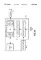
- FIG. 1illustrates a system constructed according to the invention for determining loft and speed of a sporting vehicle carrying the system
- FIGS. 2, 2A and 2Bshow illustrative uses for the system 10 shown in FIG. 1;
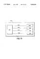
- FIG. 3illustrates a user interface and display suitable for use in the system of FIG. 1;
- FIG. 4is a representative vibrational spectrum, shown illustratively, for calculating "air” or loft time in accord with the invention
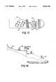
- FIG. 5shows a microphone-based loft sensor constructed according to the invention and which is suitable for use in the system of FIG. 1;
- FIG. 6shows a switch-based loft sensor constructed according to the invention and which is suitable for use in the system of FIG. 1;
- FIG. 7shows a capacitance-based loft sensor constructed according to the invention and which is suitable for use in the system of FIG. 1;
- FIG. 12illustrates a Doppler-based approach to sensing speed in accordance with the invention
- FIG. 12Ashows a laser-based Doppler speed sensor constructed according to the invention
- FIG. 12Bshows an ultrasonic-based Doppler speed sensor constructed according to the invention
- FIG. 13illustrates an accelerometer-based speed sensor constructed according to the invention and which is suitable for use as both the speed and loft sensors of FIG. 1;
- FIG. 14schematically illustrates process methodology of converting a plurality of acceleration values to speed, in accord with the invention
- FIG. 14Aschematically illustrates a process methodology of calculating speed, direction, and vehicle height, in accord with the invention, by utilizing the accelerometer-based sensors of the invention
- FIGS. 16 and 16Aillustrate a magnetic/voltage-based speed sensor constructed according to the invention
- FIG. 16Bshows relative motions, magnetic field directions, and voltages associated with the sensor of FIGS. 16 and 16A;
- FIG. 17illustrates an improvement to a snowboard in accord with the invention.
- FIG. 18illustrates one use of the invention for detecting speed, "air,” and distance in the sport of ski flying (or ski jumping) in accord with the invention.
- the system 10is incorporated into a relatively small housing, shown by the outline 24.
- the housing 24is preferably arranged to protect the components 12,14,16,18 and 20 from the elements of nature - such as rain, snow, sand and dust, each of which is expected during the ordinary course of usage on a ski slope and/or mountain bike trail.
- the housing 24is attachable to a vehicle, such as a ski or mountain bike, by means such as a glue or a mechanical mount, e.g., screws.
- the housing(and hence the system 10) is incorporated integrally with the vehicle, such as inside a ski, such that only the display 16 and user interface 14 are visible and accessible.
- the housing 24is attached or mounted to a sporting device, such as a ski or mountain bike, such that a user of the ski or mountain bike can access the system 10.
- a sporting devicesuch as a ski or mountain bike
- the speed sensor 18sends velocity information (over communication line 11a) to the microprocessor subsystem 12; while the loft sensor 20 sends loft or "air" time information (over communication line 11b) to the microprocessor subsystem 12.
- the speed information and loft time informationare processed by the microprocessor subsystem 12 to quantify actual speed, e.g., in miles per hour, and actual loft time, e.g., in seconds.
- the actual speed and loft timeare thereafter stored in internal memory 13 until, at least, the speed and time data are accessed by a user of the system 10.
- a user of the system 10can command the display of the speed and loft time data (sent across communication line 11d) on the display 16 in order to evaluate his or her performance in the sporting activity.
- the speed and loft informationcan be stored prior to processing by the microprocessor subsystem 12; and later post-processed for display on the display 16 when commanded by a user of the system 10.
- Such an embodimentmay be useful to conserve energy and to perform calculations to quantify the speed and loft data in a "batch" mode, such as known to those skilled in the art.
- FIGS. 2, 2A and 2Bshow typical uses of the system 10 illustrated in FIG. 1.
- FIG. 2shows the system 10 mounted onto a ski 26.
- the ski 26is mounted to a skier 28 (for illustrative purposes, the skier 28 is only partially illustrated), via a ski boot 30 and binding 30a, and generally descends down a ski slope 32 with a velocity 34.
- one use of the system 10is to calculate the peak speed of the ski 26 (and hence the skier 28) over a selectable period of time, e.g., during the time of descent down the slope 32.
- FIG. 1Another use of the system 10 of FIG. 1 is to calculate the loft, or "air” time of the ski 26 (and hence the user 28) during the descent down the slope 32.
- FIG. 2Awhich illustrates the positions of the ski 26' and skier 28' during a lofting maneuver on the slope 32'.
- the ski 26' and skier 28'speed down the slope 32' and launch into the air 36 at position "a," and later land at position "b” in accord with the well-known Newtonian laws of physics.
- the system 10calculates and stores the total "air” time that the ski 26' (and hence the skier 28') experience between the positions "a" and "b” so that the skier 28' can access and assess the "air” time information.
- the display 16can be one of any assortment of displays known to those skilled in the art.
- LCDsliquid crystal displays
- Other suitable displayscan include an array of light emitting diodes (LEDs) arranged to display numbers.
- FIG. 3illustrates a user interface 50 and display 52 constructed according to the invention and which are suitable for use, respectively, as the interface 14 and display 16 of FIG. 1.
- Outline 54illustrates the outline of a system constructed according to the invention, e.g., the housing outline 24 of the system 10 of FIG. 1.
- user interface 50includes control buttons.
- one embodiment of the user interface 50includes a start/stop button 58, a display-operate button 60, and a speed/loft toggle button 62. These buttons operate as follows:
- the display 52is normally OFF--and not drawing power from the associated power source (e.g., the power source 22 of FIG. 1) - and is turned ON only when a user activates the display-operate button 52.
- the ON and OFF display conditionsare preferably obtained in one of two ways: in one embodiment of the invention, the display 52 automatically turns OFF after a preselected time through the control of the microprocessor subsystem 12 of FIG. 1; or, in an alternative embodiment, the display 52 remains activated until a user again presses the display-operate button 60.
- one portion 64 of the displaydenotes whether speed or loft information is being displayed. For example, as illustrated, a "L" letter denotes that loft information is being displayed. An “S” letter likewise denotes that speed information is being displayed.
- the "air" timeis also displayed in FIG. 3 as 2.46 seconds, which represents the "air" time of a typical ski jump.
- one embodiment of the inventiondoes not include the speed/loft toggle button 62 because, as noted earlier, certain embodiments of the invention do not include both the speed sensor and loft sensor. In such an embodiment, it is unnecessary to include a toggle button 62.
- the display 52 of FIG. 3also shows another feature of the invention, namely that a system constructed according to the invention preferably calculates and stores successive records relating to speed and loft information relative to a user's activity. For example, a skier may catch "air" time more than once during a given activity; and the system of the invention can store successive loft times for access by the user. Most often, the peak "air" time is displayed, by default. However, certain users wish to evaluate successive loft time information and, accordingly, the system 10 of FIG. 1 preferably determines and stores the successive information (described in greater detail below).
- a usercan access the successive loft time information by toggling a combination of the buttons 58-62, such as known to those skilled in the art (e.g., a combination of holding one button down while pressing another button); or by including yet another button 66 on the user interface 50.
- a display portion 68 of the display 52shows a number corresponding to the sequential information on display. For example, the illustrated "1" number means that the highest "air" time record is currently being displayed; while a number greater than one means that a loft time other than the highest loft time is being displayed.
- the highest number displayed within the portion 68refers to the total number of "air" times for the selected activity period (thus for example a user can determine the total number of jumps achieved for a given day).
- successive speed informationcan be displayed much the way successive "air" time information is stored and displayed, described above.
- the speed/loft toggle button 62is pressed once to display "S" in the display portion 64, and a user can toggle button 66 to view the successive speed records as denoted by the number in display portion 68.
- this informationis not deemed very useful except under a very few circumstances--since a user generally moves with some velocity during a given activity--and thus, generally, the peak speed achieved during a given activity is normally displayed on the display 52 when commanded by the speed/loft toggle button 62.
- a button 67is used to alter the modes of the system so that other information such as average "air” time may be calculated and displayed by the invention.
- FIG. 3illustrates a display portion 69 that shows a letter "A,” corresponding to information relating to averages.
- a usercan press button 69 to display "air” time as a running average of all the successive "air” times (in such an embodiment, the display portion 68 is preferably OFF because the information displayed in portion 68 refers to successive peak information).
- the button 67is pressed once again, causing the microprocessor subsystem 12 to change the display information from integrated average values to peak values (accordingly, the display portion 69 preferably shows a "P" to identify to the user that peak information is being displayed; and the display portion 68 is preferably ON in this "peak” mode to denote which successive record is being displayed).
- the button 67is pressed once again, causing the microprocessor subsystem 12 to show the integrated "air” or speed information (depending on the toggle of the speed/loft toggle button 62).
- Integrated valuesare preferably displayed by indicating to the user a "T" (for total) in the display portion 69.
- buttons and/or combinations of buttonscan be incorporated within the user interface 50 within the scope of the invention.
- the microprocessor subsystem 12 of FIG. 1stores much information during the sporting activity and which can be converted to different forms, e.g., averages, peaks, and totals.
- different buttons and combinations of buttonscan be used to access all of the available information.
- other informationcan be denoted, for example, within the display portion 69 to identify the different types of information available within the system.
- yet another form of information which may be of interest to sporting personsis the "dead" time, i.e., the time that the person is not skiing or biking during the day.
- a person who hangs out in the bar during part of the afternoonwill not have a high efficiency factor for actual ski time as compared to the available ski time.
- This efficiency informationis available in accord with the invention because the microprocessor subsystem 12 of FIG. 1 preferably includes a clock element (readily known to those skilled in the art) for indicating processed time over a selectable period (the microprocessor subsystem 12 can in fact include a 24- hour clock element, much the way a digital wrist-watch includes 24-hour information). Accordingly, a user can start the system 10 of FIG.
- the microprocessor subsystem 12keeps track of the elapsed time between the start and stop of the system (i.e., the selectable time period), thereby providing means for determining the user's "dead” time for the day. That is, the microprocessor subsystem 12 calculates "dead” time by intelligently calculating the total time lapse within which a vibrational noise spectrum (described in more detail below in connection with FIG.
- Dead time informationis thereafter easily determined by subtracting 80% from 100%, to get 20% dead time.
- the dead time informationis shown, for example, by toggling the button 67 to a dead time mode, denoted as "D," in the display portion 69, and displaying the dead time as a percentage in the display 52.
- the real activity timeis displayed as a percentage in the display 52 by toggling the button 69 until "R" shows up in the display portion 69.
- the loft sensor 20may be constructed by several known components.
- the sensor 20is either an accelerometer or a microphone assembly.
- the sensor 20may be constructed as a mechanical switch that detects the presence and absence of weight onto the switch. Each of these alternatives is described below.
- An accelerometerdetects acceleration and provides a voltage output that is proportional to the detected acceleration. Accordingly, the accelerometer senses vibration--particularly the vibration of a vehicle such as a ski or mountain bike--moving along a surface, e.g., a ski slope or mountain bike trail. This voltage output provides an acceleration spectrum over time; and information about loft time can be ascertained by performing calculations on that spectrum. Specifically, the microprocessor subsystem 12 of FIG. 1 stores the spectrum into memory 13 and processes the spectrum information to determine "air" time.
- FIG. 4also shows that the spectrum stops at the end 78 of the sporting activity, such as when the user of the system again presses the start/stop button 58, FIG. 3.
- a usercan simply start the system 10 of FIG. 1 at the beginning of the day, by toggling the start/stop button 58, and stop the system 10 at the end of the day, by again toggling the start/stop button 58.
- the issue hereis that there may be apparent "air” times between the starting and stopping of the system which is not, in fact, the "air” time of interest. For example, standing in line at a ski lift represents a period within which the spectrum 72 appears smooth, and might be mistaken for "air” time.
- the microprocessor subsystem 12 of the inventionpreferably includes process boundary conditions within which "air" time will be excluded.
- Another boundary conditionconcerns the type of skier using the system. Some skiers often make quick jump turns down the mountain. These would normally show up as mini "air” times.
- another boundary conditionis: if the spectrum between any given "t1" time and "t2" time (FIG. 4) is less than 500 ms, then exclude that time from memory as actual “air” time. Accordingly, each jump turn will not be included in the total "air” time for the day, as is expected by users of the system.
- Another embodiment of the inventioninternally resets the start/stop button 58 when the system senses the lack of spectral information for a preselected period of time. Thus, after the preselected period, the system has an automatic time-out, resulting in the microprocessor subsystem 12 resetting itself as if the start/stop button 58 were pushed.
- Accelerometersare commercially available and are relatively cheap items. They are also small, so that all of the components 12, 14, 16 and 20 may easily fit within a small, lightweight housing. Suitable accelerometers include those accelerometers shown and described in connection with FIGS. 13, 14 and 14A.
- microphonesare also commercially available and are relatively cheap. They are also small, so that all of the components 12, 14, 16 and 20 may easily fit within a small, lightweight housing.
- the senor 80 of FIG. 1can be a switch that rests below the boot of the ski, e.g., the boot 30 of FIG. 2, and that senses pressure caused by the weight of the user within the boot. That is, when the skier is on the ground, the boot squeezes the switch, thereby closing the switch.
- the closed switchis detected by the microprocessor subsystem 12 (FIG. 1) as a discrete input.
- the switchopens up by virtue of the fact that relatively no weight is on the switch; and this opened switch is also detected and input into microprocessor subsystem 12.
- the microprocessor subsystem 12will count at known time intervals (clock rates) for the duration of the opened switch, corresponding to the jump, and will record how long the jump lasts.
- the "air” timemay be recorded as a single jump, or recorded as a successive list of jumps.
- the "air” timecan be summed or integrated into a running total, such as described above.
- FIG. 7Another embodiment of the invention which is suitable for use as the loft sensor 20, FIG. 1, includes a pad that is placed under the skier's boot and that changes capacitance as a function of a change of applied pressure.
- FIG. 7(again with illustrative ski boot 100) which shows a compressible material 112 and a capacitance-changing element 114 that changes capacitance under varying applied pressures.
- This capacitance-changing element 112is connected in circuit 116, including the illustrative battery element 118 and resistor 120, with the system of the invention such that its capacitance is converted to a digital signal by conditioning electronics, such as shown in FIG. 8.
- conditioning electronicssuch as shown in FIG. 8.
- FIG. 8the circuit of FIG.
- FIG. 7is shown illustratively and without the other necessary components (e.g., the microprocessor subsystem) of the invention.
- the components 112, 114, 115, 116, 118 and 120connect integrally with a system (e.g., the system 10 of FIG. 1) constructed according to the invention.
- a capacitorconsists of two parallel plates separated by a dielectric material.
- the capacitanceis directly proportional to the cross sectional area of the plates and inversely proportional to the distance between the plates.
- the dielectricis the compressible material 112, FIG. 7, then the pressure applied to the material 112 changes the distance between the plates 115a, 115b of the capacitance-changing element 114, thereby proportionately increasing the capacitance.
- FIG. 8shows a monostable multivibrator 122, e.g., a NE555, in accord with the invention which converts the varying capacitance (illustrated as portion 124) from the capacitance-changing element 114 of FIG. 7 to information suitable for calculating "air" time.
- a resistor 126connects in circuit with the portion 124 and the multivibrator 122.
- the output pulse train 128is directly dependent on the product of the resistance "R” and variable capacitance "C".
- the change in capacitancecan be used in a filter which passes a pulse train during low capacitance levels (no boot pressure) and which filters out the pulse train during high capacitance events (high boot pressure).
- a capacitance-changing element 130e.g., the capacitance-changing circuit 116 of FIG. 7 connects to the input of a Schmidtt Trigger CMOS gate 133 and ground.
- a pulse generator 131connects through a fixed resistor R 132 to the capacitance-changing element 133 and the Schmidtt Trigger CMOS gate 133. The pulse generator 131 produces a steady pulse train 134.
- the capacitance changing element 130When the capacitance changing element 130 is at a high capacitance, corresponding to a high boot pressure meaning that the ski is on the ground, the combination of the fixed resistance R 132 and the capacitance of the capacitance-changing element 130 absorbs the pulse train and the output of the Schmidtt Trigger CMOS gate 133 is constant.
- the capacitance of the capacitance-changing element 130when the skier takes flight, the capacitance of the capacitance-changing element 130 is low, thus allowing the pulse train 134 to pass through to the Schmidtt Trigger CMOS gate 133 input.
- the output of the Schmidtt Trigger CMOS gate 133in this latter case toggles at the same rate as the pulse train 131, thereby identifying a condition of "air” time. A discrete input is thus used by the processor to sample for the existence of the pulse train to calculate "air" time.
- the microprocessor subsystem 10 of FIG. 1can include a microcontroller element, a microcontroller element with reduced functionality to conserve power, or a microprocessor element with associated memory and logic to perform the requisite calculations of the invention, including the processing power to drive the display 16 and user interface 14.
- the microprocessor subsystem 12is constructed by several known components, such as shown in FIG. 10.
- FIG. 10shows microprocessor subsystem 150 constructed according to the invention and including a Central Processing Unit (CPU) 152, memory 154, interface electronics 156, and conditioning electronics 158.
- the user interface 160such as the interface 14 of FIG. 1, and including the button inputs of FIG. 3, connects to the subsystem such as shown and directly to the conditioning electronics 158.
- the display 162, such as the display 16 of FIG. 1,preferably connects to the subsystem such as shown and directly to the CPU 152.
- the CPU 152includes a microprocessor 152a, Read Only Memory (ROM) 152b (used to store instructions that the processor may fetch in executing its program), Random Access Memory (RAM) 152c (used by the processor to store temporary information such as return addresses for subroutines and variables and constant values defined in a processor program), and a master clock 152d.
- the microprocessor 152ais controlled by the master dock 152d that provides a master timing signal used to sequence the microprocessor 152a through its internal states in its execution of each processed instruction.
- the clock 152dis the master time source through which time may be deduced in measuring velocity or air time (for example, to determine the elapsed time from one event to another, such as the lapsed time "t1" to "t2" of FIG. 4, the clock rate provides a direct measure of time lapse).
- the subsystem 150stores information about the user's activity in memory.
- This memorymay be external to the CPU 152, such as shown as memory 154, but preferably resides in the RAM 152c.
- the memorymay be nonvolatile such as battery backed RAM or Electrically Erasable Programmable Read Only Memory (EEPROM).
- External signals 164 from the speed and/or loft sensors, e.g., the speed sensor 18 and loft sensor 20 of FIG. 1,are connected to the conditioning electronics 158 which filters, scales, and, in some cases, senses the presence of certain conditions, such as zero crossings. This conditioning essentially cleans the signal up for processing by the CPU 152 and in some cases preprocesses the information.
- These signalsare then passed to the interface electronics 156, which converts the analog voltage or currents to binary ones and zeroes understood by the CPU 152.
- the speed sensor 118 of FIG. 1can take one of several forms, including: (1) a pitch detection system that detects the "pitch" of the vibrational spectrum and that converts the pitch to an equivalent speed; (2) a laser-based or sound-based Doppler-shift sensor; (3) an accelerometer-based speed sensor; (4) a pressure-based speed sensor; and (5) a voltage-resistance sensor
- processing logicsuch as described herein in connection with the microprocessor subsystem can be incorporated, at least in part, within one or both of the speed and loft sensors. Because of the complexity of the speed sensor, such preprocessing power is more appropriately within the speed sensor.
- no separate speed sensor elemente.g., the sensor 18 of FIG. 1
- the vibrational spectrum that is generated by the loft sensor 20, and particularly the accelerometer or microphone embodiment discussed in connection with FIG. 4will be used to determine the pitch of the vibration and, thereby, the equivalent speed.
- a skiergenerates a scraping sound on hard-packed snow and ice.
- that scraping soundchanges in pitch.
- the spectrum shown in FIG. 4 outside the t1/t2 region(but within the "start” and "end” region) is, effectively, that pitch.
- the speed of the vehiclee.g., ski and mountain bike
- the speed of the vehiclemay be determined by spectral content.
- This spectral contentmay be determined, in part, by the conditioning electronics 158 of FIG. 10 such to determining rise times to infer a bandwidth of the information.
- the conditioning electronics 158 and/or CPU 152can also measure the time between successive zero crossings, which also determines spectral content.
- FIG. 11illustrates a spectrum 166 generated from a sensor such as a sensor 18 or 20 (FIG. 1), or 82 (FIG. 5), or 202a-202d (FIG. 13 below).
- the spectrum 166thus represents an acceleration spectrum or sound spectrum such as described herein.
- the microprocessor subsystem 12 of FIG. 1evaluates the spectrum 166 and generates a best-fit sine wave 167 to match the primary frequency of the spectrum 166 over time.
- FIG. 11shows illustratively a situation where a vehicle, such as a ski, moves slowly at first, corresponding to a lower sine-wave frequency, then faster, corresponding to a higher frequency sine wave, and then slower again.
- This pitch transitionis interpreted by the microprocessor subsystem (e.g., the subsystem 12 of FIG. 1) as a change of speed.
- the microprocessor subsystem of the inventionis calibrated in this embodiment to associate a certain frequency with a certain speed; and speed is thus known for the variety of pitches observed during an activity, such as illustrated in FIG. 11.
- the pitch informationis surface dependent (and vehicle dependent). That is, a ski-over-snow-speed-spectrum has a different spectrum than a bicycle-over-ground-spectrum. Accordingly, different calibrations must be made for different vehicles and speeds, in accord with the invention. Further, certain spectrums may actually decrease in frequency as speed increases; which also must be calibrated to obtain the correct speed information. These calibrations are typically programmed into the microprocessor subsystem memory, e.g., the memory 13 of subsystem 12 of FIG. 1. Further, in certain embodiments of the invention, the system stores different spectrum calibrations for different activities so that a user can move the system from one sport to another. Accordingly, one or more buttons such as the buttons 58-67 of FIG. 3 are introduced to the user interface, such as known to those skilled in the art, in order to selectively access the different spectrum calibrations.
- Doppler radaris used by police vehicles to detect speed.
- the same principlesapply to the measurement of speed of the sporting vehicle. For example, consider FIG. 12.
- FIG. 12shows a representative ski 170 (partially shown) with a Doppler-based sensor 172 mounted thereon (for illustrative purposes, the Doppler-based sensor is shown without the other elements of the system, such as the user interface and microprocessor).
- the sensorgenerates an electromagnetic beam 174, such as a laser beam, to bounce off the ground 176 (e.g., the ski slope) while the user of the system conducts the activity (e.g., skiing).
- the electromagnetic beam 174is reflected off the ground by particles 178 which scatter at least a portion of the energy back to the sensor 172 along approximately the same path.
- the returned energyis at a slightly different frequency from the outgoing frequency; hence the Doppler shift, which is a measurable quantity.
- the sensor 172must be arranged to generate a beam along the side (or in front or back of) the ski in order to "see" the ground 176.
- the energy beam 174is generated in one of two general ways: by a laser diode (to generate a laser beam) or by a piezoelectric transducer (to produce an ultrasonic beam).
- FIG. 12ashows a sensor 172' comprising a laser diode 180.
- the diode 180generates a laser beam 174' which is reflected by the particles 178' back to the sensor 172'.
- a small beam-splitting mirror 182reflects part of the returned beam to a detector 184 which is connected under the overall control of the microprocessor subsystem 186, e.g., the subsystem 12 of FIG.
- the subsystem 186evaluates the frequency difference between the outgoing beam from the diode 180 and the returned frequency from the detector 184.
- the frequency differenceis readily converted to speed that is displayed on the display, e.g., the display 16 of FIG. 1.
- FIG. 12bshows a sensor 172" comprising a piezoelectric transducer 190 which generates an ultrasonic beam 174" that reflects from particles 178" back to the piezo transducer 190, which is connected under the overall control of the microprocessor subsystem 192, e.g., the subsystem 12 of FIG. 1 (for illustrative purposes, the other elements of the system of the invention, e.g., the user interface, are not shown in FIG. 11b).
- the microprocessor subsystem 192generates a voltage at a set frequency to drive the piezoelectric transducer 190, to thereby generate the beam 174".
- the reflected Doppler-shifted beamreturns through the transducer 190 (alternatively, through another piezo transducer (not shown)) and generates a voltage at the frequency of the reflected beam.
- the subsystem 192evaluates the frequency difference between the outgoing ultrasonic beam 174" and the returned frequency. As above, the frequency difference is readily converted to speed (via a conversion technique that is known to those skilled in the art) that is displayed on the display, e.g., the display 16 of FIG. 1.
- Modem navigation systemsutilize a plurality of accelerometers to determine speed and direction.
- Particularly complex military systemsfor example, utilize three translational and three rotational accelerometers to track direction and speed even during complex angular movements and at extremely high velocities.
- a similar plurality of accelerometersis used to determine speed.
- one goal of the inventionis to track speeds of sporting vehicles (e.g., a ski) that generally travel in one direction, namely forward. Therefore, the complexity of the accelerometer package is reduced since the orientation of the sensor may be fixed to the vehicle; and fewer than six accelerometers can be used to determine speed.
- Accelerometersare well-known to those skilled in the art. They include, for example, translational and rotational accelerometers.
- FIG. 13illustrates a speed sensor 200 constructed according to the invention and which includes a plurality of accelerometers 202a-202d.
- the accelerometers 202a-202dsense various accelerations in their respective axes (accelerometers sense acceleration along a predefined axis, translational or rotational), and each of the outputs from the accelerometers are input to the microprocessor subsystem 204, e.g., the subsystem 12 of FIG. 1, via communication lines 206a-206d.
- each accelerometer 202a-202dThe orientation of the sensitive axis of each accelerometer 202a-202d is stored in the microprocessor subsystem 204 so that a particular acceleration in one axis is properly combined with acceleration values in other axes (as described in more detail below in connection with FIGS. 14 and 14a).
- one or more of the accelerometers 202a-202dare used to determine and measure the force or gravity relative to the angle of the vehicle (e.g., the ski) so that gravity may be compensated for by the subsystem 204.
- gravitytends to reduce or increase the measured acceleration output; and that reduction or increase must be adjusted for or else the conversion from acceleration to speed (i.e., the integral of acceleration over time) will be next to useless.
- the orientations of the accelerometers 202a-202d relative to their respective sensitive axesmust be known by the subsystem 204 in order to compensate for the acceleration of gravity, which is generally perpendicular to the motion of the vehicle, but which has a component acceleration in the direction of movement when the vehicle is pointed downwards or upwards.
- any of the accelerometers 202a-202d of FIG. 13can be used, in accord with the invention, as the loft sensor 20 of FIG. 1 and without a separate component to measure "air" time. This is because each of the accelerometers 202a-202d generate a spectrum such as described in connection with FIG. 4. Accordingly, one or more of the accelerometers 202a-202d can be used to determine "air" time, described above, without the need for a separate loft sensor.
- FIG. 14schematically illustrates process methodology, according to the invention, which converts a plurality of acceleration inputs to speed.
- a plurality of six accelerometerse.g., similar to the accelerometers 202a-202d of FIG. 13
- the process methodology of the inventionis preferably shown in FIG. 14.
- six accelerometersare connected with various sensitive orientations to collect pitch 207a yaw 207b, roll 207c, surge 207d, heave 207e, and sway 207f accelerations.
- accelerationsare conditioned by the conditioning electronics 158' through the interface electronics 156' and CPU 152' to calculate speed, such as known to those skilled in the art of navigational engineering (for example, Gyroscopic Theory, Design, and Instrumentation by Wrigley et al., MIT Press (1969); Handbook of Measurement and Control by Herceg et al, Schaevitz Engineering, Pensauker, NJ, Library of Congress 76-24971 (1976); and Inertial Navigation Systems by Broxmeyer, McGraw-Hill (1964) describe such calculations and are hereby incorporated herein by reference).
- the elements 158', 156' and 152'are similar in construction to the elements 158, 156 and 152 described in connection with FIG. 10.
- FIG. 14Aschematically illustrates further process methodologies according to the invention wherein the six acceleration inputs 207a-207f are processed by the microprocessor subsystem of the invention (e.g., subsystem 12 of FIG. 1) such that centripetal, gravitational, and earth rate compensations are performed so that the various accelerations are properly integrated and compensated to derive speed (and even direction and distance).
- a microprocessor subsystem of the FIG. 14A embodimentincludes a centripetal acceleration compensation section 208a which compensates for motions of centripetal accelerations via inputs of surge 207d, heave 207e, and sway 207f.
- a gravity acceleration compensation section 208b in the subsystemfurther processes these inputs 207d-207f to compensate for the acceleration of gravity, while a earth rate compensation section 208c thereafter compensates for the accelerations induced by the earth's rotation (e.g., the earth rate acceleration at the equator is approximately opposite in direction to the force of gravity).
- FIG. 14AAlso shown in FIG. 14A are translational integrators 209a-209c which convert the compensated accelerations from inputs 207d-207f to translational velocities by integration.
- Integrators 210a-210clikewise integrate inputs of pitch 207ayaw 207b, and roll 207c to angular velocity while integrators 211a-211c provide a further integration to convert the angular velocities to angular position.
- the angular positional information and translational velocity informationis combined and processed at the speed and direction resolution section 212 to derive speed and direction.
- the subsystem with the components 208, 209, 210, 211 and 212is calibrated prior to use; and such calibration includes a calibration to true North (for a calibration of earth rate).
- the inventionfurther provides, in one embodiment, information for displaying height achieved during any given "air" time, as described above.
- the accelerometers of FIG. 13-14provide sufficiently detailed information such that the whole of the system according to the invention can be mounted to a user of the system directly, rather than directly to a vehicle.
- movements of the human bodye.g., centripetal motions
- Such compensationsrequire powerful processing power.
- Pressure of the airis used in aviation to determine how high an aircraft is. The higher the altitude the lower the air pressure.
- Pressure sensors according to the inventionconvert air pressure to an analog voltage.
- the pressure sensor 221When mounted to a snowboard 220, such as shown in FIGS. 15 and 15A, the pressure sensor 221 is used to determine the altitude of the snowboarder.
- This voltageis read by the microprocessor subsystem (e.g., the subsystem 12 of FIG. 1) at a fixed rate and differentiated to determine rate of descent or speed in the vertical direction. This may be converted to speed along the path by knowing the grade or angle of descent. Angle of descent is known by predetermining the geometry of the ski path or by the addition of a inclinometer 222 which gives a voltage dependent upon the angle, with respect to vertical, of the platform.
- the inclinometer 222measures zero when the ski is traveling along a level path and the pressure sensor is showing a constant pressure.
- the inclinometer 222measures the angle of descent and the pressure sensor measures ever increasing pressure. Since the angle of descent is known, as is the rate of descent, the true speed is determined and displayed.
- elements 221 and 222are connected in circuit with the further elements of the invention, e.g., the microprocessor subsystem 12 of FIG. 1; and that elements 221 and 222 are shown in FIG. 15 for illustrative purposes only when in fact they exist integrally with the system of the invention, e.g., the system 10 of FIG. 1.
- Under-water vehicles and many oceanographic instrumentsmeasure water velocity by taking advantage of the principle discovered by Faraday that a conductor moving through a magnetic field produces a voltage across the conductor. The voltage produced is greatest when the conductor is orthogonal to the magnetic field and orthogonal to the direction of motion. This principal is used, in accord with the invention, to determine the speed that a skier moves over the snow in winter skiing or over the water in water skiing.
- an electromagnet 241is mounted to a snowboard 242.
- Two contacts 240a, 240bare mounted to the snowboard 242 such that the bottom 243a makes contact with the snow and the top 243b of the contacts are connected to a voltage-measuring circuit within the conditioning electronics (such as the electronics 158 of FIG. 10 and such as known to those skilled in the art).
- the conditioning electronicssuch as the electronics 158 of FIG. 10 and such as known to those skilled in the art.
- This voltage 246is read by the microprocessor subsystem (e.g., the subsystem 12 of FIG. 1). When the voltage abruptly goes to zero, and thereafter returns to a high voltage, the microprocessor subsystem determines that the gap in voltage is "air” time. Accordingly, in such an embodiment, no separate sensor 20 is required to measure "air” time (such as described above).
- FIGS. 16-16Bare shown illustratively for ease of understanding and without the further necessary elements of the invention, e.g., the microprocessor subsystem 12 of FIG. 1.
- FIG. 17shows such an improvement to a snowboard in accord with the invention.
- a snowboard 270, with boot holder 271incorporates a system 272 constructed according to the invention.
- the system 272like the system 10 of FIG. 1, has a display 274, a user interface 276 that provides a user with buttons to selectively access speed and loft time, as described above, and one or more display portions 278 to display identification information about the displayed times (such as described in connection with FIG. 3).
- FIG. 18shows yet another use of the invention.
- Ski flyingis similar to ski jumping except that ski jumping uses special, extralong skis, while ski flying uses standard alpine skis.
- the participant 300skis down the long ramp 302, which may be as high as twenty-five stories, and launches horizontally into the air at the end 304 of the ramp 302.
- the objective of the sportis for the participant 300 to "jump” or "fly” through the air for as long as possible, and covering the greatest distance as possible.
- a system constructed according to the invention(not shown) is attached to the ski 310 to measure "air" time, speed, and distance, as described herein.
- the speed at the end 304is used to predict distance by well-known Newtonian physics so that the participant's overall jump distance is calculated. This removes the necessity of having judges and/or other expensive equipment monitor the event, as the recorded "air" and jump distance is readily displayed by the system of the invention.
Landscapes
- Health & Medical Sciences (AREA)
- Physics & Mathematics (AREA)
- General Physics & Mathematics (AREA)
- Life Sciences & Earth Sciences (AREA)
- General Health & Medical Sciences (AREA)
- Engineering & Computer Science (AREA)
- Heart & Thoracic Surgery (AREA)
- Dentistry (AREA)
- Biophysics (AREA)
- Pathology (AREA)
- Physiology (AREA)
- Biomedical Technology (AREA)
- Oral & Maxillofacial Surgery (AREA)
- Medical Informatics (AREA)
- Molecular Biology (AREA)
- Surgery (AREA)
- Animal Behavior & Ethology (AREA)
- Public Health (AREA)
- Veterinary Medicine (AREA)
- Physical Education & Sports Medicine (AREA)
- Measurement Of Unknown Time Intervals (AREA)
Abstract
Description
Claims (16)
Priority Applications (37)
| Application Number | Priority Date | Filing Date | Title |
|---|---|---|---|
| US08/344,485US5636146A (en) | 1994-11-21 | 1994-11-21 | Apparatus and methods for determining loft time and speed |
| US08/764,758US5960380A (en) | 1994-11-21 | 1996-12-12 | Apparatus and methods for determining loft time and speed |
| US08/867,083US6266623B1 (en) | 1994-11-21 | 1997-06-02 | Sport monitoring apparatus for determining loft time, speed, power absorbed and other factors such as height |
| US09/353,530US6496787B1 (en) | 1994-11-21 | 1999-07-14 | Apparatus and method for determining loft time and speed |
| US09/784,783US6516284B2 (en) | 1994-11-21 | 2001-02-15 | Speedometer for a moving sportsman |
| US09/784,774US6499000B2 (en) | 1994-11-21 | 2001-02-15 | System and method for determining loft time, speed, height and distance |
| US09/886,578US6498994B2 (en) | 1994-11-21 | 2001-06-21 | Systems and methods for determining energy experienced by a user and associated with activity |
| US09/992,966US6885971B2 (en) | 1994-11-21 | 2001-11-06 | Methods and systems for assessing athletic performance |
| US10/234,660US6856934B2 (en) | 1994-11-21 | 2002-09-04 | Sport monitoring systems and associated methods |
| US10/289,039US6963818B2 (en) | 1994-11-21 | 2002-11-06 | Mobile speedometer system and associated methods |
| US10/842,947US7072789B2 (en) | 1994-11-21 | 2004-05-11 | Systems for assessing athletic performance |
| US10/950,897US7054784B2 (en) | 1994-11-21 | 2004-09-27 | Sport monitoring systems |
| US11/221,029US7162392B2 (en) | 1994-11-21 | 2005-09-07 | Sport performance systems for measuring athletic performance, and associated methods |
| US11/243,945US7949488B2 (en) | 1994-11-21 | 2005-10-05 | Movement monitoring systems and associated methods |
| US11/434,588US7451056B2 (en) | 1994-11-21 | 2006-05-15 | Activity monitoring systems and methods |
| US11/484,199US7158912B2 (en) | 1994-11-21 | 2006-07-10 | Mobile GPS systems for providing location mapping and/or performance data |
| US11/495,112US7457724B2 (en) | 1994-11-21 | 2006-07-28 | Shoes and garments employing one or more of accelerometers, wireless transmitters, processors, altimeters, to determine information such as speed to persons wearing the shoes or garments |
| US11/598,410US7386401B2 (en) | 1994-11-21 | 2006-11-13 | Helmet that reports impact information, and associated methods |
| US11/599,123US7433805B2 (en) | 1994-11-21 | 2006-11-14 | Pressure sensing systems for sports, and associated methods |
| US11/601,406US7813887B2 (en) | 1994-11-21 | 2006-11-17 | Location determining system |
| US11/747,081US7512515B2 (en) | 1994-11-21 | 2007-05-10 | Activity monitoring systems and methods |
| US11/864,748US7640135B2 (en) | 1994-11-21 | 2007-09-28 | System and method for determining airtime using free fall |
| US12/135,893US7693668B2 (en) | 1994-11-21 | 2008-06-09 | Impact reporting head gear system and method |
| US12/207,032US7623987B2 (en) | 1994-11-21 | 2008-09-09 | Shoes and garments employing one or more of accelerometers, wireless transmitters, processors, altimeters, to determine information such as speed to persons wearing the shoes or garments |
| US12/210,844US7966154B2 (en) | 1994-11-21 | 2008-09-15 | Pressure sensing systems for sports, and associated methods |
| US12/370,795US8036851B2 (en) | 1994-11-21 | 2009-02-13 | Activity monitoring systems and methods |
| US12/538,004US7983876B2 (en) | 1994-11-21 | 2009-08-07 | Shoes and garments employing one or more of accelerometers, wireless transmitters, processors altimeters, to determine information such as speed to persons wearing the shoes or garments |
| US12/753,658US7860666B2 (en) | 1994-11-21 | 2010-04-02 | Systems and methods for determining drop distance and speed of moving sportsmen involved in board sports |
| US12/897,427US8762092B2 (en) | 1994-11-21 | 2010-10-04 | Location determining system |
| US12/942,857US7991565B2 (en) | 1994-11-21 | 2010-11-09 | System and method for non-wirelessly determining free-fall of a moving sportsman |
| US13/077,534US8463573B2 (en) | 1994-11-21 | 2011-03-31 | Movement monitoring systems and associated methods |
| US13/164,351US8249831B2 (en) | 1994-11-21 | 2011-06-20 | Pressure sensing systems for sports, and associated methods |
| US13/190,098US8239146B2 (en) | 1994-11-21 | 2011-07-25 | Board sports sensing devices, and associated methods |
| US13/231,624US8352211B2 (en) | 1994-11-21 | 2011-09-13 | Activity monitoring systems and methods |
| US13/548,344US8600699B2 (en) | 1994-11-21 | 2012-07-13 | Sensing systems for sports, and associated methods |
| US13/567,895US8620600B2 (en) | 1994-11-21 | 2012-08-06 | System for assessing and displaying activity of a sportsman |
| US13/894,085US8849606B2 (en) | 1994-11-21 | 2013-05-14 | Movement monitoring systems and associated methods |
Applications Claiming Priority (1)
| Application Number | Priority Date | Filing Date | Title |
|---|---|---|---|
| US08/344,485US5636146A (en) | 1994-11-21 | 1994-11-21 | Apparatus and methods for determining loft time and speed |
Related Parent Applications (3)
| Application Number | Title | Priority Date | Filing Date |
|---|---|---|---|
| US08/764,758Continuation-In-PartUS5960380A (en) | 1994-11-21 | 1996-12-12 | Apparatus and methods for determining loft time and speed |
| US10/842,947ContinuationUS7072789B2 (en) | 1994-11-21 | 2004-05-11 | Systems for assessing athletic performance |
| US11/864,748Continuation-In-PartUS7640135B2 (en) | 1994-11-21 | 2007-09-28 | System and method for determining airtime using free fall |
Related Child Applications (5)
| Application Number | Title | Priority Date | Filing Date |
|---|---|---|---|
| US08/764,758ContinuationUS5960380A (en) | 1994-11-21 | 1996-12-12 | Apparatus and methods for determining loft time and speed |
| US08/764,758Continuation-In-PartUS5960380A (en) | 1994-11-21 | 1996-12-12 | Apparatus and methods for determining loft time and speed |
| US08/867,083Continuation-In-PartUS6266623B1 (en) | 1994-11-21 | 1997-06-02 | Sport monitoring apparatus for determining loft time, speed, power absorbed and other factors such as height |
| US08/867,083ContinuationUS6266623B1 (en) | 1994-11-21 | 1997-06-02 | Sport monitoring apparatus for determining loft time, speed, power absorbed and other factors such as height |
| US09/089,232ContinuationUS6539336B1 (en) | 1994-11-21 | 1998-06-02 | Sport monitoring system for determining airtime, speed, power absorbed and other factors such as drop distance |
Publications (1)
| Publication Number | Publication Date |
|---|---|
| US5636146Atrue US5636146A (en) | 1997-06-03 |
Family
ID=23350723
Family Applications (4)
| Application Number | Title | Priority Date | Filing Date |
|---|---|---|---|
| US08/344,485Expired - LifetimeUS5636146A (en) | 1994-11-21 | 1994-11-21 | Apparatus and methods for determining loft time and speed |
| US08/764,758Expired - LifetimeUS5960380A (en) | 1994-11-21 | 1996-12-12 | Apparatus and methods for determining loft time and speed |
| US09/353,530Expired - LifetimeUS6496787B1 (en) | 1994-11-21 | 1999-07-14 | Apparatus and method for determining loft time and speed |
| US09/784,774Expired - LifetimeUS6499000B2 (en) | 1994-11-21 | 2001-02-15 | System and method for determining loft time, speed, height and distance |
Family Applications After (3)
| Application Number | Title | Priority Date | Filing Date |
|---|---|---|---|
| US08/764,758Expired - LifetimeUS5960380A (en) | 1994-11-21 | 1996-12-12 | Apparatus and methods for determining loft time and speed |
| US09/353,530Expired - LifetimeUS6496787B1 (en) | 1994-11-21 | 1999-07-14 | Apparatus and method for determining loft time and speed |
| US09/784,774Expired - LifetimeUS6499000B2 (en) | 1994-11-21 | 2001-02-15 | System and method for determining loft time, speed, height and distance |
Country Status (1)
| Country | Link |
|---|---|
| US (4) | US5636146A (en) |
Cited By (99)
| Publication number | Priority date | Publication date | Assignee | Title |
|---|---|---|---|---|
| US5761096A (en)* | 1996-11-01 | 1998-06-02 | Zakutin; David | Speed-sensing projectile |
| WO1999018480A1 (en)* | 1997-10-02 | 1999-04-15 | Personal Electronic Devices, Inc. | Measuring foot contact time and foot loft time of a person in locomotion |
| US6122340A (en)* | 1998-10-01 | 2000-09-19 | Personal Electronic Devices, Inc. | Detachable foot mount for electronic device |
| US6167356A (en)* | 1998-07-01 | 2000-12-26 | Sportvision, Inc. | System for measuring a jump |
| WO2001001706A1 (en)* | 1999-06-30 | 2001-01-04 | Phatrat Technology, Inc. | Event and sport performance methods and systems |
| EP0919267A3 (en)* | 1997-11-27 | 2001-04-18 | Konami Co., Ltd. | Simulation game machine |
| WO2001005298A3 (en)* | 1999-07-14 | 2001-05-10 | Reebok Int Ltd | Performance and entertainment device and method of using the same |
| US6298314B1 (en) | 1997-10-02 | 2001-10-02 | Personal Electronic Devices, Inc. | Detecting the starting and stopping of movement of a person on foot |
| WO2001071372A3 (en)* | 2000-03-23 | 2002-03-21 | Yeoman Group Plc | Navigational aid |
| US20020077784A1 (en)* | 2000-05-03 | 2002-06-20 | Vock Curtis A. | Sensor and event system, and associated methods |
| US20020107649A1 (en)* | 2000-12-27 | 2002-08-08 | Kiyoaki Takiguchi | Gait detection system, gait detection apparatus, device, and gait detection method |
| US20020164929A1 (en)* | 2000-04-05 | 2002-11-07 | Pinson Jay D. | Method of polishing and cleaning substrates |
| WO2002093272A1 (en)* | 2000-12-15 | 2002-11-21 | Phatrat Technology, Inc. | Movement and event systems and associated methods related applications |
| US6493652B1 (en) | 1997-10-02 | 2002-12-10 | Personal Electronic Devices, Inc. | Monitoring activity of a user in locomotion on foot |
| US6533296B1 (en)* | 2001-05-18 | 2003-03-18 | Eric A. Farraday | Snow board system |
| US20030055595A1 (en)* | 1994-11-21 | 2003-03-20 | Peter Flentov | Mobile speedometer system and associated methods |
| US6560903B1 (en) | 2000-03-07 | 2003-05-13 | Personal Electronic Devices, Inc. | Ambulatory foot pod |
| US20030093248A1 (en)* | 1996-12-12 | 2003-05-15 | Vock Curtis A. | Mobile speedometer system, and associated methods |
| US6611789B1 (en)* | 1997-10-02 | 2003-08-26 | Personal Electric Devices, Inc. | Monitoring activity of a user in locomotion on foot |
| US20030163287A1 (en)* | 2000-12-15 | 2003-08-28 | Vock Curtis A. | Movement and event systems and associated methods related applications |
| US20040064252A1 (en)* | 2002-09-26 | 2004-04-01 | Honeywell International Inc. | Method and system for processing pulse signals within an inertial navigation system |
| EP1406066A3 (en)* | 2002-09-16 | 2004-08-25 | Tobias Kramer | Distance and velocity measuring apparatus for skis and snowboards |
| WO2004059240A3 (en)* | 2002-12-30 | 2004-12-29 | Tobias Kramer | Distance and speed measuring device for skis and snowboards |
| US20050038626A1 (en)* | 1994-11-21 | 2005-02-17 | Peter Flentov | Sport monitoring systems |
| US6876947B1 (en) | 1997-10-02 | 2005-04-05 | Fitsense Technology, Inc. | Monitoring activity of a user in locomotion on foot |
| US6882955B1 (en) | 1997-10-02 | 2005-04-19 | Fitsense Technology, Inc. | Monitoring activity of a user in locomotion on foot |
| US20060167623A1 (en)* | 2005-01-25 | 2006-07-27 | Alexander Jeffrey M | Hang timer for determining time of flight of an object |
| US20060167649A1 (en)* | 2005-01-25 | 2006-07-27 | Alexander Jeffrey M | Enhanced hang-timer for console simulation |
| US20060283050A1 (en)* | 2005-03-31 | 2006-12-21 | Adidas International Marketing B.V. | Shoe housing |
| US20070000154A1 (en)* | 2003-03-10 | 2007-01-04 | Christian Dibenedetto | Intelligent footwear systems |
| US20070011920A1 (en)* | 2003-03-10 | 2007-01-18 | Adidas International Marketing B.V. | Intelligent footwear systems |
| US20070061107A1 (en)* | 1994-11-21 | 2007-03-15 | Vock Curtis A | Pressure sensing systems for sports, and associated methods |
| US20070112542A1 (en)* | 2000-12-15 | 2007-05-17 | Vock Curtis A | Methods for determining weight of a person |
| US7225565B2 (en) | 2003-03-10 | 2007-06-05 | Adidas International Marketing B.V. | Intelligent footwear systems |
| US7237446B2 (en) | 2005-09-16 | 2007-07-03 | Raymond Chan | System and method for measuring gait kinematics information |
| US20070156369A1 (en)* | 2006-01-03 | 2007-07-05 | Alexander Jeffrey M | Hang-timer for providing recording instructions |
| US20070173355A1 (en)* | 2006-01-13 | 2007-07-26 | Klein William M | Wireless sensor scoring with automatic sensor synchronization |
| US20070197938A1 (en)* | 2005-12-14 | 2007-08-23 | Tyson William R | Performance tracking systems and methods |
| US20070208544A1 (en)* | 2006-03-03 | 2007-09-06 | Garmin Ltd. | Method and apparatus for estimating a motion parameter |
| US20080015061A1 (en)* | 2006-07-11 | 2008-01-17 | Klein William M | Performance monitoring in a shooting sport using sensor synchronization |
| US20080255794A1 (en)* | 2006-10-11 | 2008-10-16 | Levine James A | Physical activity monitoring and prompting system |
| US20090015421A1 (en)* | 2007-07-12 | 2009-01-15 | Arto Niva | Portable Apparatus |
| US20090191988A1 (en)* | 2008-01-24 | 2009-07-30 | Klein William M | Real-time wireless sensor scoring |
| US20090216543A1 (en)* | 2005-06-30 | 2009-08-27 | Lg Electronics, Inc. | Method and apparatus for encoding and decoding an audio signal |
| US7643895B2 (en) | 2006-05-22 | 2010-01-05 | Apple Inc. | Portable media device with workout support |
| US20100063778A1 (en)* | 2008-06-13 | 2010-03-11 | Nike, Inc. | Footwear Having Sensor System |
| US7698101B2 (en) | 2007-03-07 | 2010-04-13 | Apple Inc. | Smart garment |
| US7696905B2 (en) | 1996-05-22 | 2010-04-13 | Qualcomm Incorporated | Method and apparatus for controlling the operational mode of electronic devices in response to sensed conditions |
| US7739076B1 (en) | 1999-06-30 | 2010-06-15 | Nike, Inc. | Event and sport performance methods and systems |
| US20100185398A1 (en)* | 2009-01-22 | 2010-07-22 | Under Armour, Inc. | System and Method for Monitoring Athletic Performance |
| US20100204615A1 (en)* | 2006-01-20 | 2010-08-12 | 6Th Dimension Devices Inc. | Method and system for assessing athletic performance |
| US7813715B2 (en) | 2006-08-30 | 2010-10-12 | Apple Inc. | Automated pairing of wireless accessories with host devices |
| US20100262573A1 (en)* | 1998-12-18 | 2010-10-14 | Microsoft Corporation | Logging and analyzing computer user's context data |
| US7913297B2 (en) | 2006-08-30 | 2011-03-22 | Apple Inc. | Pairing of wireless devices using a wired medium |
| US7911339B2 (en) | 2005-10-18 | 2011-03-22 | Apple Inc. | Shoe wear-out sensor, body-bar sensing system, unitless activity assessment and associated methods |
| US20110199393A1 (en)* | 2008-06-13 | 2011-08-18 | Nike, Inc. | Foot Gestures for Computer Input and Interface Control |
| US20110218758A1 (en)* | 1994-11-21 | 2011-09-08 | Nike, Inc. | Movement monitoring systems and associated methods |
| US8055469B2 (en) | 2006-03-03 | 2011-11-08 | Garmin Switzerland Gmbh | Method and apparatus for determining the attachment position of a motion sensing apparatus |
| US8073984B2 (en) | 2006-05-22 | 2011-12-06 | Apple Inc. | Communication protocol for use with portable electronic devices |
| US8231487B2 (en) | 2004-09-17 | 2012-07-31 | Adidas International Marketing B.V. | Bladder |
| US8739639B2 (en) | 2012-02-22 | 2014-06-03 | Nike, Inc. | Footwear having sensor system |
| US8968156B2 (en) | 2001-02-20 | 2015-03-03 | Adidas Ag | Methods for determining workout plans and sessions |
| US9042596B2 (en) | 2012-06-14 | 2015-05-26 | Medibotics Llc | Willpower watch (TM)—a wearable food consumption monitor |
| US20150168438A1 (en)* | 2013-12-13 | 2015-06-18 | Seiko Instruments Inc. | Electronic device, data processing method and data processing program |
| US9060682B2 (en) | 2012-10-25 | 2015-06-23 | Alpinereplay, Inc. | Distributed systems and methods to measure and process sport motions |
| US9089182B2 (en) | 2008-06-13 | 2015-07-28 | Nike, Inc. | Footwear having sensor system |
| US9137309B2 (en) | 2006-05-22 | 2015-09-15 | Apple Inc. | Calibration techniques for activity sensing devices |
| US9192816B2 (en) | 2011-02-17 | 2015-11-24 | Nike, Inc. | Footwear having sensor system |
| US9254099B2 (en) | 2013-05-23 | 2016-02-09 | Medibotics Llc | Smart watch and food-imaging member for monitoring food consumption |
| US9279734B2 (en) | 2013-03-15 | 2016-03-08 | Nike, Inc. | System and method for analyzing athletic activity |
| US9305120B2 (en) | 2011-04-29 | 2016-04-05 | Bryan Marc Failing | Sports board configuration |
| US9381420B2 (en) | 2011-02-17 | 2016-07-05 | Nike, Inc. | Workout user experience |
| US9389057B2 (en) | 2010-11-10 | 2016-07-12 | Nike, Inc. | Systems and methods for time-based athletic activity measurement and display |
| US9411940B2 (en) | 2011-02-17 | 2016-08-09 | Nike, Inc. | Selecting and correlating physical activity data with image data |
| US9442100B2 (en) | 2013-12-18 | 2016-09-13 | Medibotics Llc | Caloric intake measuring system using spectroscopic and 3D imaging analysis |
| US9529385B2 (en) | 2013-05-23 | 2016-12-27 | Medibotics Llc | Smart watch and human-to-computer interface for monitoring food consumption |
| US9536449B2 (en) | 2013-05-23 | 2017-01-03 | Medibotics Llc | Smart watch and food utensil for monitoring food consumption |
| US9549585B2 (en) | 2008-06-13 | 2017-01-24 | Nike, Inc. | Footwear having sensor system |
| WO2017025109A1 (en)* | 2015-08-10 | 2017-02-16 | Nira Dynamics Ab | Velocity estimation |
| US9642415B2 (en) | 2011-02-07 | 2017-05-09 | New Balance Athletics, Inc. | Systems and methods for monitoring athletic performance |
| US9694247B2 (en) | 2013-02-15 | 2017-07-04 | Adidas Ag | Ball for a ball sport |
| US9743861B2 (en) | 2013-02-01 | 2017-08-29 | Nike, Inc. | System and method for analyzing athletic activity |
| US9756895B2 (en) | 2012-02-22 | 2017-09-12 | Nike, Inc. | Footwear having sensor system |
| US9763489B2 (en) | 2012-02-22 | 2017-09-19 | Nike, Inc. | Footwear having sensor system |
| US9841330B2 (en) | 2012-12-13 | 2017-12-12 | Nike, Inc. | Apparel having sensor system |
| US20180001139A1 (en)* | 2016-06-29 | 2018-01-04 | Stephanie Moyerman | Accelerated pattern recognition in action sports |
| US9868041B2 (en) | 2006-05-22 | 2018-01-16 | Apple, Inc. | Integrated media jukebox and physiologic data handling application |
| US10070680B2 (en) | 2008-06-13 | 2018-09-11 | Nike, Inc. | Footwear having sensor system |
| US10314492B2 (en) | 2013-05-23 | 2019-06-11 | Medibotics Llc | Wearable spectroscopic sensor to measure food consumption based on interaction between light and the human body |
| US10363453B2 (en) | 2011-02-07 | 2019-07-30 | New Balance Athletics, Inc. | Systems and methods for monitoring athletic and physiological performance |
| US10568381B2 (en) | 2012-02-22 | 2020-02-25 | Nike, Inc. | Motorized shoe with gesture control |
| US10751568B2 (en)* | 2016-12-12 | 2020-08-25 | The Swatch Group Research And Development Ltd | Method of detecting and calculating height of a jump |
| US10926133B2 (en) | 2013-02-01 | 2021-02-23 | Nike, Inc. | System and method for analyzing athletic activity |
| US11006690B2 (en) | 2013-02-01 | 2021-05-18 | Nike, Inc. | System and method for analyzing athletic activity |
| CN113624996A (en)* | 2021-09-07 | 2021-11-09 | 珠海格力电器股份有限公司 | Cargo throwing state identification method and system |
| US11350853B2 (en) | 2018-10-02 | 2022-06-07 | Under Armour, Inc. | Gait coaching in fitness tracking systems |
| US11684111B2 (en) | 2012-02-22 | 2023-06-27 | Nike, Inc. | Motorized shoe with gesture control |
| CN117398100A (en)* | 2023-12-14 | 2024-01-16 | 合肥综合性国家科学中心人工智能研究院(安徽省人工智能实验室) | Lower limb strength test method, system, terminal equipment and computer storage medium |
| US12082650B1 (en) | 2023-08-15 | 2024-09-10 | Richard Peter Anderson | Ski boot and related system |
Families Citing this family (41)
| Publication number | Priority date | Publication date | Assignee | Title |
|---|---|---|---|---|
| JP4376342B2 (en)* | 1999-03-02 | 2009-12-02 | セイコーインスツル株式会社 | Electronic clock |
| US6527711B1 (en) | 1999-10-18 | 2003-03-04 | Bodymedia, Inc. | Wearable human physiological data sensors and reporting system therefor |
| US20060122474A1 (en) | 2000-06-16 | 2006-06-08 | Bodymedia, Inc. | Apparatus for monitoring health, wellness and fitness |
| US7285090B2 (en)* | 2000-06-16 | 2007-10-23 | Bodymedia, Inc. | Apparatus for detecting, receiving, deriving and displaying human physiological and contextual information |
| US7689437B1 (en)* | 2000-06-16 | 2010-03-30 | Bodymedia, Inc. | System for monitoring health, wellness and fitness |
| WO2005029242A2 (en)* | 2000-06-16 | 2005-03-31 | Bodymedia, Inc. | System for monitoring and managing body weight and other physiological conditions including iterative and personalized planning, intervention and reporting capability |
| PT1292218E (en) | 2000-06-23 | 2006-09-29 | Bodymedia Inc | SYSTEM FOR HEALTH, WELL-BEING AND APPROPRIATE SURVEILLANCE |
| US20030104782A1 (en) | 2001-11-30 | 2003-06-05 | Palm, Inc. | Object tagging system and method |
| US7946959B2 (en)* | 2002-05-30 | 2011-05-24 | Nike, Inc. | Training scripts |
| US7020508B2 (en) | 2002-08-22 | 2006-03-28 | Bodymedia, Inc. | Apparatus for detecting human physiological and contextual information |
| US20070100666A1 (en)* | 2002-08-22 | 2007-05-03 | Stivoric John M | Devices and systems for contextual and physiological-based detection, monitoring, reporting, entertainment, and control of other devices |
| US7182738B2 (en) | 2003-04-23 | 2007-02-27 | Marctec, Llc | Patient monitoring apparatus and method for orthosis and other devices |
| US20050195094A1 (en)* | 2004-03-05 | 2005-09-08 | White Russell W. | System and method for utilizing a bicycle computer to monitor athletic performance |
| WO2005092177A1 (en) | 2004-03-22 | 2005-10-06 | Bodymedia, Inc. | Non-invasive temperature monitoring device |
| US7191089B2 (en) | 2004-12-01 | 2007-03-13 | Freescale Semiconductor, Inc. | System and method for fall detection |
| US7487045B1 (en) | 2005-03-10 | 2009-02-03 | William Vieira | Projected score area calculator and method of use |
| EP3057016A1 (en) | 2007-02-14 | 2016-08-17 | NIKE Innovate C.V. | Collection and display of athletic information |
| US20080320029A1 (en) | 2007-02-16 | 2008-12-25 | Stivoric John M | Lifeotype interfaces |
| US20090010021A1 (en)* | 2007-07-06 | 2009-01-08 | Smith Jeffrey T | Recreational apparatus and method of making the same |
| US8221290B2 (en) | 2007-08-17 | 2012-07-17 | Adidas International Marketing B.V. | Sports electronic training system with electronic gaming features, and applications thereof |
| US8360904B2 (en) | 2007-08-17 | 2013-01-29 | Adidas International Marketing Bv | Sports electronic training system with sport ball, and applications thereof |
| US8702430B2 (en) | 2007-08-17 | 2014-04-22 | Adidas International Marketing B.V. | Sports electronic training system, and applications thereof |
| US9288751B2 (en)* | 2007-08-29 | 2016-03-15 | Qualcomm Incorporated | Use of position data to select wireless access point |
| EP2108962A3 (en)* | 2008-04-11 | 2011-12-28 | Continental Teves AG & Co. oHG | Device and method for calculating the speed of an athlete |
| US20100211350A1 (en)* | 2009-02-17 | 2010-08-19 | Yung-Hung Chih | Speed meter |
| US20100206070A1 (en)* | 2009-02-17 | 2010-08-19 | Yung-Hung Chih | Speed meter having pedometric function |
| US9855484B1 (en) | 2009-04-24 | 2018-01-02 | Mayfonk Athletic, Llc | Systems, methods, and apparatus for measuring athletic performance characteristics |
| US8253586B1 (en) | 2009-04-24 | 2012-08-28 | Mayfonk Art, Inc. | Athletic-wear having integral measuring sensors |
| US9354447B2 (en) | 2010-01-18 | 2016-05-31 | Intel Corporation | Head mounted information systems and related methods |
| US8332544B1 (en) | 2010-03-17 | 2012-12-11 | Mattel, Inc. | Systems, methods, and devices for assisting play |
| US8917203B2 (en)* | 2011-06-21 | 2014-12-23 | Honeywell International Inc. | Motion-based adaptive frequency estimation of a doppler velocity sensor |
| US10548514B2 (en) | 2013-03-07 | 2020-02-04 | Alpinereplay, Inc. | Systems and methods for identifying and characterizing athletic maneuvers |
| US10008237B2 (en) | 2012-09-12 | 2018-06-26 | Alpinereplay, Inc | Systems and methods for creating and enhancing videos |
| US9566021B2 (en) | 2012-09-12 | 2017-02-14 | Alpinereplay, Inc. | Systems and methods for synchronized display of athletic maneuvers |
| US10408857B2 (en) | 2012-09-12 | 2019-09-10 | Alpinereplay, Inc. | Use of gyro sensors for identifying athletic maneuvers |
| US9135347B2 (en) | 2013-12-18 | 2015-09-15 | Assess2Perform, LLC | Exercise tracking and analysis systems and related methods of use |
| WO2016134031A1 (en) | 2015-02-17 | 2016-08-25 | Alpinereplay, Inc | Systems and methods to control camera operations |
| CN105233459B (en)* | 2015-10-16 | 2019-02-01 | 湖南师范大学 | Long-jump training device and its method |
| US10321208B2 (en) | 2015-10-26 | 2019-06-11 | Alpinereplay, Inc. | System and method for enhanced video image recognition using motion sensors |
| EP3199213B1 (en) | 2016-01-29 | 2020-07-29 | Swiss Timing Ltd. | Method and system for measuring the speed of a competitor on a running track |
| US12303742B2 (en)* | 2022-06-30 | 2025-05-20 | Gomore Inc. | Method and device for predicting sports performance, and computer readable storage medium |
Citations (7)
| Publication number | Priority date | Publication date | Assignee | Title |
|---|---|---|---|---|
| US3978725A (en)* | 1976-01-07 | 1976-09-07 | Robert Hain Associates, Inc. | Speedometer particularly for water skis |
| US4089057A (en)* | 1977-01-17 | 1978-05-09 | Eriksson Karl Erik | Method and device for measuring jump-lengths on a ski-jump |
| US4371945A (en)* | 1980-12-01 | 1983-02-01 | Lawrence Joseph Karr | Electronic pedometer |
| US4722222A (en)* | 1986-09-25 | 1988-02-02 | Skisonics Corporation | Ski speedometer |
| US4757714A (en)* | 1986-09-25 | 1988-07-19 | Insight, Inc. | Speed sensor and head-mounted data display |
| US5295085A (en)* | 1992-02-25 | 1994-03-15 | Avocet, Inc. | Pressure measurement device with selective pressure threshold crossings accumulator |
| US5343445A (en)* | 1993-07-06 | 1994-08-30 | David Stern | Athletic shoe with timing device |
Family Cites Families (21)
| Publication number | Priority date | Publication date | Assignee | Title |
|---|---|---|---|---|
| JPS5313752B2 (en)* | 1972-05-30 | 1978-05-12 | ||
| US4371188A (en) | 1980-06-24 | 1983-02-01 | University Of California | Method for programmed release in ski bindings |
| US4516110A (en) | 1982-08-09 | 1985-05-07 | Mark Overmyer | Ski stress signaling device |
| US4780837A (en)* | 1984-06-23 | 1988-10-25 | Aloka Co., Ltd. | Doppler signal frequency converter |
| DE3432596A1 (en)* | 1984-09-05 | 1986-03-06 | Pötsch, Edmund Reinfried, 8901 Königsbrunn | ACCELERATION AND / OR SPEED AND / OR ROUTE OR TILT ANGLE MEASUREMENT ARRANGEMENT |
| DE3505521A1 (en)* | 1985-02-18 | 1986-08-21 | Puma-Sportschuhfabriken Rudolf Dassler Kg, 8522 Herzogenaurach | APPENDIX FOR DETERMINING THE MOVEMENT PROCESSES OF RUNNING DISCIPLINES |
| US5033013A (en) | 1985-04-22 | 1991-07-16 | Yamasa Tokei Meter Co., Ltd. | Method and apparatus for measuring the amount of exercise |
| US4694694A (en) | 1986-01-06 | 1987-09-22 | Vertical Instruments, Inc. | Solid state accumulating altimeter |
| US4757453A (en) | 1986-03-25 | 1988-07-12 | Nasiff Roger E | Body activity monitor using piezoelectric transducers on arms and legs |
| FR2616337B1 (en)* | 1987-06-10 | 1989-07-07 | Ecole Nale Equitation | METHOD FOR ANALYZING AND SIMULATING THE MOVEMENTS OF A HORSE |
| US4876500A (en)* | 1988-08-03 | 1989-10-24 | Wu Chuan Chueng | User carried sensor for detecting displacement relative to the ground |
| DE3937841A1 (en)* | 1988-11-14 | 1990-05-17 | Atsugi Unisia Corp | ROAD RUNNING SYSTEM FOR A SUSPENSION CONTROL AND MOTOR VEHICLE SUSPENSION CONTROL SYSTEM USING THE DETECTED ROAD RUNNESS AS A CONTROL PARAMETER |
| US5144226A (en) | 1991-05-17 | 1992-09-01 | Core Industries | Multi-mode measuring system |
| US5471405A (en) | 1992-11-13 | 1995-11-28 | Marsh; Stephen A. | Apparatus for measurement of forces and pressures applied to a garment |
| JP3220271B2 (en)* | 1993-02-22 | 2001-10-22 | セイコーインスツルメンツ株式会社 | Pedometer with pulse meter |
| US5574669A (en)* | 1993-05-28 | 1996-11-12 | Marshall; William R. | Device for measuring foot motion and method |
| US5446775A (en)* | 1993-12-20 | 1995-08-29 | Wright; Larry A. | Motion detector and counter |
| US5485402A (en)* | 1994-03-21 | 1996-01-16 | Prosthetics Research Study | Gait activity monitor |
| US5690591A (en) | 1994-09-12 | 1997-11-25 | Nec Corporation | Ski training apparatus |
| US5671162A (en) | 1995-10-23 | 1997-09-23 | Werbin; Roy Geoffrey | Device for recording descent data for skydiving |
| US5724265A (en) | 1995-12-12 | 1998-03-03 | Hutchings; Lawrence J. | System and method for measuring movement of objects |
- 1994
- 1994-11-21USUS08/344,485patent/US5636146A/ennot_activeExpired - Lifetime
- 1996
- 1996-12-12USUS08/764,758patent/US5960380A/ennot_activeExpired - Lifetime
- 1999
- 1999-07-14USUS09/353,530patent/US6496787B1/ennot_activeExpired - Lifetime
- 2001
- 2001-02-15USUS09/784,774patent/US6499000B2/ennot_activeExpired - Lifetime
Patent Citations (8)
| Publication number | Priority date | Publication date | Assignee | Title |
|---|---|---|---|---|
| US3978725A (en)* | 1976-01-07 | 1976-09-07 | Robert Hain Associates, Inc. | Speedometer particularly for water skis |
| US4089057A (en)* | 1977-01-17 | 1978-05-09 | Eriksson Karl Erik | Method and device for measuring jump-lengths on a ski-jump |
| US4371945A (en)* | 1980-12-01 | 1983-02-01 | Lawrence Joseph Karr | Electronic pedometer |
| US4722222A (en)* | 1986-09-25 | 1988-02-02 | Skisonics Corporation | Ski speedometer |
| US4757714A (en)* | 1986-09-25 | 1988-07-19 | Insight, Inc. | Speed sensor and head-mounted data display |
| US5295085A (en)* | 1992-02-25 | 1994-03-15 | Avocet, Inc. | Pressure measurement device with selective pressure threshold crossings accumulator |
| US5343445A (en)* | 1993-07-06 | 1994-08-30 | David Stern | Athletic shoe with timing device |
| US5452269A (en)* | 1993-07-06 | 1995-09-19 | David Stern | Athletic shoe with timing device |
Cited By (274)
| Publication number | Priority date | Publication date | Assignee | Title |
|---|---|---|---|---|
| US7512515B2 (en) | 1994-11-21 | 2009-03-31 | Apple Inc. | Activity monitoring systems and methods |
| US20110022357A1 (en)* | 1994-11-21 | 2011-01-27 | Nike, Inc. | Location determining system |
| US8762092B2 (en) | 1994-11-21 | 2014-06-24 | Nike, Inc. | Location determining system |
| US8849606B2 (en) | 1994-11-21 | 2014-09-30 | Nike, Inc. | Movement monitoring systems and associated methods |
| US8620600B2 (en) | 1994-11-21 | 2013-12-31 | Phatrat Technology, Llc | System for assessing and displaying activity of a sportsman |
| US8600699B2 (en) | 1994-11-21 | 2013-12-03 | Nike, Inc. | Sensing systems for sports, and associated methods |
| US8463573B2 (en)* | 1994-11-21 | 2013-06-11 | Nike, Inc. | Movement monitoring systems and associated methods |
| US8352211B2 (en) | 1994-11-21 | 2013-01-08 | Apple Inc. | Activity monitoring systems and methods |
| US20060265187A1 (en)* | 1994-11-21 | 2006-11-23 | Vock Curtis A | Shoes and garments employing one or more of accelerometers, wireless transmitters, processors, altimeters, to determine information such as speed to persons wearing the shoes or garments |
| US8249831B2 (en) | 1994-11-21 | 2012-08-21 | Nike, Inc. | Pressure sensing systems for sports, and associated methods |
| US8239146B2 (en) | 1994-11-21 | 2012-08-07 | PhatRat Technology, LLP | Board sports sensing devices, and associated methods |
| US7054784B2 (en) | 1994-11-21 | 2006-05-30 | Phatrat Technology, Inc. | Sport monitoring systems |
| US8036851B2 (en) | 1994-11-21 | 2011-10-11 | Apple Inc. | Activity monitoring systems and methods |
| US20110218758A1 (en)* | 1994-11-21 | 2011-09-08 | Nike, Inc. | Movement monitoring systems and associated methods |
| US7991565B2 (en) | 1994-11-21 | 2011-08-02 | Phatrat Technology, Llc | System and method for non-wirelessly determining free-fall of a moving sportsman |
| US7983876B2 (en) | 1994-11-21 | 2011-07-19 | Nike, Inc. | Shoes and garments employing one or more of accelerometers, wireless transmitters, processors altimeters, to determine information such as speed to persons wearing the shoes or garments |
| US7966154B2 (en) | 1994-11-21 | 2011-06-21 | Nike, Inc. | Pressure sensing systems for sports, and associated methods |
| US7433805B2 (en) | 1994-11-21 | 2008-10-07 | Nike, Inc. | Pressure sensing systems for sports, and associated methods |
| US7860666B2 (en) | 1994-11-21 | 2010-12-28 | Phatrat Technology, Llc | Systems and methods for determining drop distance and speed of moving sportsmen involved in board sports |
| US7813887B2 (en) | 1994-11-21 | 2010-10-12 | Nike, Inc. | Location determining system |
| US20030055595A1 (en)* | 1994-11-21 | 2003-03-20 | Peter Flentov | Mobile speedometer system and associated methods |
| US20070061107A1 (en)* | 1994-11-21 | 2007-03-15 | Vock Curtis A | Pressure sensing systems for sports, and associated methods |
| US6963818B2 (en) | 1994-11-21 | 2005-11-08 | Phatrat Technology, Inc. | Mobile speedometer system and associated methods |
| US20070061106A1 (en)* | 1994-11-21 | 2007-03-15 | Vock Curtis A | Helmet that reports impact information, and associated methods |
| US7693668B2 (en) | 1994-11-21 | 2010-04-06 | Phatrat Technology, Llc | Impact reporting head gear system and method |
| US20100036639A1 (en)* | 1994-11-21 | 2010-02-11 | Nike, Inc. | Shoes and Garments Employing One or More of Accelerometers, Wireless Transmitters, Processors Altimeters, to Determine Information Such as Speed to Persons Wearing the Shoes or Garments |
| US7640135B2 (en) | 1994-11-21 | 2009-12-29 | Phatrat Technology, Llc | System and method for determining airtime using free fall |
| US7623987B2 (en) | 1994-11-21 | 2009-11-24 | Nike, Inc. | Shoes and garments employing one or more of accelerometers, wireless transmitters, processors, altimeters, to determine information such as speed to persons wearing the shoes or garments |
| US20070067128A1 (en)* | 1994-11-21 | 2007-03-22 | Vock Curtis A | Location determining system |
| US20090063097A1 (en)* | 1994-11-21 | 2009-03-05 | Vock Curtis A | Pressure sensing systems for sports, and associated methods |
| US7386401B2 (en) | 1994-11-21 | 2008-06-10 | Phatrat Technology, Llc | Helmet that reports impact information, and associated methods |
| US20050038626A1 (en)* | 1994-11-21 | 2005-02-17 | Peter Flentov | Sport monitoring systems |
| US20090006029A1 (en)* | 1994-11-21 | 2009-01-01 | Nike, Inc. | Shoes and Garments Employing One or More of Accelerometers, Wireless Transmitters, Processors Altimeters, to Determine Information Such as Speed to Persons Wearing the Shoes or Garments |
| US7457724B2 (en) | 1994-11-21 | 2008-11-25 | Nike, Inc. | Shoes and garments employing one or more of accelerometers, wireless transmitters, processors, altimeters, to determine information such as speed to persons wearing the shoes or garments |
| US7451056B2 (en) | 1994-11-21 | 2008-11-11 | Phatrat Technology, Llc | Activity monitoring systems and methods |
| US20100185303A1 (en)* | 1996-05-22 | 2010-07-22 | Qualcomm Incorporated | Method and apparatus for controlling the operational mode of electronic devices in response to sensed conditions |
| US7696905B2 (en) | 1996-05-22 | 2010-04-13 | Qualcomm Incorporated | Method and apparatus for controlling the operational mode of electronic devices in response to sensed conditions |
| US9009505B2 (en) | 1996-05-22 | 2015-04-14 | Qualcomm Incorporated | Method and apparatus for controlling the operational mode of electronic devices in response to sensed conditions |
| US5946643A (en)* | 1996-11-01 | 1999-08-31 | Zakutin; David | Speed-sensing projectile |
| US5761096A (en)* | 1996-11-01 | 1998-06-02 | Zakutin; David | Speed-sensing projectile |
| US20050021292A1 (en)* | 1996-12-12 | 2005-01-27 | Vock Curtis A. | Systems and methods for determining performance data |
| US6959259B2 (en) | 1996-12-12 | 2005-10-25 | Phatrat Technology, Inc. | System and methods for determining performance data |
| US20030093248A1 (en)* | 1996-12-12 | 2003-05-15 | Vock Curtis A. | Mobile speedometer system, and associated methods |
| US7092846B2 (en) | 1996-12-12 | 2006-08-15 | Phatrat Technology, Inc. | Systems and methods for determining performance data |
| US7962312B2 (en) | 1997-10-02 | 2011-06-14 | Nike, Inc. | Monitoring activity of a user in locomotion on foot |
| US7428471B2 (en) | 1997-10-02 | 2008-09-23 | Nike, Inc. | Monitoring activity of a user in locomotion on foot |
| US6018705A (en)* | 1997-10-02 | 2000-01-25 | Personal Electronic Devices, Inc. | Measuring foot contact time and foot loft time of a person in locomotion |
| US8712725B2 (en) | 1997-10-02 | 2014-04-29 | Nike, Inc. | Monitoring activity of a user in locomotion on foot |
| US6611789B1 (en)* | 1997-10-02 | 2003-08-26 | Personal Electric Devices, Inc. | Monitoring activity of a user in locomotion on foot |
| US6052654A (en)* | 1997-10-02 | 2000-04-18 | Personal Electronic Devices, Inc. | Measuring foot contact time and foot loft time of a person in locomotion |
| US6876947B1 (en) | 1997-10-02 | 2005-04-05 | Fitsense Technology, Inc. | Monitoring activity of a user in locomotion on foot |
| US20060020421A1 (en)* | 1997-10-02 | 2006-01-26 | Fitsense Technology, Inc. | Monitoring activity of a user in locomotion on foot |
| US6882955B1 (en) | 1997-10-02 | 2005-04-19 | Fitsense Technology, Inc. | Monitoring activity of a user in locomotion on foot |
| US7617071B2 (en) | 1997-10-02 | 2009-11-10 | Nike, Inc. | Monitoring activity of a user in locomotion on foot |
| US7200517B2 (en) | 1997-10-02 | 2007-04-03 | Nike, Inc. | Monitoring activity of a user in locomotion on foot |
| US7428472B2 (en) | 1997-10-02 | 2008-09-23 | Nike, Inc. | Monitoring activity of a user in locomotion on foot |
| US6898550B1 (en) | 1997-10-02 | 2005-05-24 | Fitsense Technology, Inc. | Monitoring activity of a user in locomotion on foot |
| US6298314B1 (en) | 1997-10-02 | 2001-10-02 | Personal Electronic Devices, Inc. | Detecting the starting and stopping of movement of a person on foot |
| US9247897B2 (en) | 1997-10-02 | 2016-02-02 | Nike, Inc. | Monitoring activity of a user in locomotion on foot |
| US6493652B1 (en) | 1997-10-02 | 2002-12-10 | Personal Electronic Devices, Inc. | Monitoring activity of a user in locomotion on foot |
| WO1999018480A1 (en)* | 1997-10-02 | 1999-04-15 | Personal Electronic Devices, Inc. | Measuring foot contact time and foot loft time of a person in locomotion |
| US20070208531A1 (en)* | 1997-10-02 | 2007-09-06 | Nike, Inc. | Monitoring activity of a user in locomotion on foot |
| US20070203665A1 (en)* | 1997-10-02 | 2007-08-30 | Nike, Inc. | Monitoring activity of a user in locomotion on foot |
| EP0919267A3 (en)* | 1997-11-27 | 2001-04-18 | Konami Co., Ltd. | Simulation game machine |
| US6471584B1 (en) | 1997-11-27 | 2002-10-29 | Konami Co., Ltd. | Simulation game machine |
| US6167356A (en)* | 1998-07-01 | 2000-12-26 | Sportvision, Inc. | System for measuring a jump |
| US6122340A (en)* | 1998-10-01 | 2000-09-19 | Personal Electronic Devices, Inc. | Detachable foot mount for electronic device |
| US6357147B1 (en) | 1998-10-01 | 2002-03-19 | Personal Electronics, Inc. | Detachable foot mount for electronic device |
| US6536139B2 (en) | 1998-10-01 | 2003-03-25 | Personal Electronic Devices, Inc. | Detachable foot mount for electronic device |
| US8626712B2 (en)* | 1998-12-18 | 2014-01-07 | Microsoft Corporation | Logging and analyzing computer user's context data |
| US20100262573A1 (en)* | 1998-12-18 | 2010-10-14 | Microsoft Corporation | Logging and analyzing computer user's context data |
| US10147265B2 (en) | 1999-06-30 | 2018-12-04 | Nike, Inc. | Mobile image capture system |
| WO2001001706A1 (en)* | 1999-06-30 | 2001-01-04 | Phatrat Technology, Inc. | Event and sport performance methods and systems |
| US20100225763A1 (en)* | 1999-06-30 | 2010-09-09 | Nike, Inc. | Event and sport performance methods and systems |
| US10071301B2 (en) | 1999-06-30 | 2018-09-11 | Nike, Inc. | Event and sport performance methods and systems |
| US7739076B1 (en) | 1999-06-30 | 2010-06-15 | Nike, Inc. | Event and sport performance methods and systems |
| WO2001005298A3 (en)* | 1999-07-14 | 2001-05-10 | Reebok Int Ltd | Performance and entertainment device and method of using the same |
| US6560903B1 (en) | 2000-03-07 | 2003-05-13 | Personal Electronic Devices, Inc. | Ambulatory foot pod |
| WO2001071372A3 (en)* | 2000-03-23 | 2002-03-21 | Yeoman Group Plc | Navigational aid |
| US6887124B2 (en) | 2000-04-05 | 2005-05-03 | Applied Materials, Inc. | Method of polishing and cleaning substrates |
| US20020164929A1 (en)* | 2000-04-05 | 2002-11-07 | Pinson Jay D. | Method of polishing and cleaning substrates |
| US20020077784A1 (en)* | 2000-05-03 | 2002-06-20 | Vock Curtis A. | Sensor and event system, and associated methods |
| US6825777B2 (en)* | 2000-05-03 | 2004-11-30 | Phatrat Technology, Inc. | Sensor and event system, and associated methods |
| US9267793B2 (en) | 2000-12-15 | 2016-02-23 | Tvipr, Llc | Movement monitoring device for attachment to equipment |
| US8126675B2 (en) | 2000-12-15 | 2012-02-28 | Phatrat Technology, Llc | Product integrity tracking shipping label, and associated method |
| US8688406B2 (en) | 2000-12-15 | 2014-04-01 | Apple Inc. | Personal items network, and associated methods |
| US7353137B2 (en) | 2000-12-15 | 2008-04-01 | Phatrat Technology, Llc | Shoe-based weight measuring system |
| US8660814B2 (en) | 2000-12-15 | 2014-02-25 | Tvipr, Llc | Package management system for tracking shipment and product integrity |
| WO2002093272A1 (en)* | 2000-12-15 | 2002-11-21 | Phatrat Technology, Inc. | Movement and event systems and associated methods related applications |
| US20140202264A1 (en)* | 2000-12-15 | 2014-07-24 | Apple Inc. | Personal items network, and associated methods |
| US9643091B2 (en) | 2000-12-15 | 2017-05-09 | Apple Inc. | Personal items network, and associated methods |
| US7620520B2 (en) | 2000-12-15 | 2009-11-17 | Phatrat Technology, Llc | Methods for determining weight of a person |
| US10080971B2 (en) | 2000-12-15 | 2018-09-25 | Apple Inc. | Personal items network, and associated methods |
| US7627451B2 (en) | 2000-12-15 | 2009-12-01 | Apple Inc. | Movement and event systems and associated methods |
| US8428904B2 (en) | 2000-12-15 | 2013-04-23 | Tvipr, Llc | Product integrity tracking system, shipping label, and associated method |
| US8396687B2 (en) | 2000-12-15 | 2013-03-12 | Phatrat Technology, Llc | Machine logic airtime sensor for board sports |
| US20070118328A1 (en)* | 2000-12-15 | 2007-05-24 | Vock Curtis A | Shoe-based weight measuring system |
| US10639552B2 (en) | 2000-12-15 | 2020-05-05 | Apple Inc. | Personal items network, and associated methods |
| US8374825B2 (en) | 2000-12-15 | 2013-02-12 | Apple Inc. | Personal items network, and associated methods |
| US20030163287A1 (en)* | 2000-12-15 | 2003-08-28 | Vock Curtis A. | Movement and event systems and associated methods related applications |
| US7856339B2 (en)* | 2000-12-15 | 2010-12-21 | Phatrat Technology, Llc | Product integrity tracking shipping label, system and associated method |
| US10427050B2 (en) | 2000-12-15 | 2019-10-01 | Apple Inc. | Personal items network, and associated methods |
| US10406445B2 (en) | 2000-12-15 | 2019-09-10 | Apple Inc. | Personal items network, and associated methods |
| US20070112542A1 (en)* | 2000-12-15 | 2007-05-17 | Vock Curtis A | Methods for determining weight of a person |
| US8280682B2 (en)* | 2000-12-15 | 2012-10-02 | Tvipr, Llc | Device for monitoring movement of shipped goods |
| US20100076692A1 (en)* | 2000-12-15 | 2010-03-25 | Vock Curtis A | Movement And Event Systems And Associated Methods |
| US7552031B2 (en) | 2000-12-15 | 2009-06-23 | Apple Inc. | Personal items network, and associated methods |
| US8280681B2 (en) | 2000-12-15 | 2012-10-02 | Phatrat Technology, Llc | Pressure-based weight monitoring system for determining improper walking or running |
| US20050192516A1 (en)* | 2000-12-27 | 2005-09-01 | Sony Corporation | Gait detection system, gait detection apparatus, device, and gait detection method |
| US20020107649A1 (en)* | 2000-12-27 | 2002-08-08 | Kiyoaki Takiguchi | Gait detection system, gait detection apparatus, device, and gait detection method |
| US6958045B2 (en)* | 2000-12-27 | 2005-10-25 | Sony Corporation | Gait detection system, gait detection apparatus, device, and gait detection method |
| US7172563B2 (en)* | 2000-12-27 | 2007-02-06 | Sony Corporation | Gait detection system, gait detection apparatus, device, and gait detection method |
| US8968156B2 (en) | 2001-02-20 | 2015-03-03 | Adidas Ag | Methods for determining workout plans and sessions |
| US6533296B1 (en)* | 2001-05-18 | 2003-03-18 | Eric A. Farraday | Snow board system |
| EP1406066A3 (en)* | 2002-09-16 | 2004-08-25 | Tobias Kramer | Distance and velocity measuring apparatus for skis and snowboards |
| US6876926B2 (en) | 2002-09-26 | 2005-04-05 | Honeywell International Inc. | Method and system for processing pulse signals within an inertial navigation system |
| US20040064252A1 (en)* | 2002-09-26 | 2004-04-01 | Honeywell International Inc. | Method and system for processing pulse signals within an inertial navigation system |
| WO2004059240A3 (en)* | 2002-12-30 | 2004-12-29 | Tobias Kramer | Distance and speed measuring device for skis and snowboards |
| US7225565B2 (en) | 2003-03-10 | 2007-06-05 | Adidas International Marketing B.V. | Intelligent footwear systems |
| US7631382B2 (en) | 2003-03-10 | 2009-12-15 | Adidas International Marketing B.V. | Intelligent footwear systems |
| US7506460B2 (en) | 2003-03-10 | 2009-03-24 | Adidas International Marketing B.V. | Intelligent footwear systems |
| US20070000154A1 (en)* | 2003-03-10 | 2007-01-04 | Christian Dibenedetto | Intelligent footwear systems |
| US20070011920A1 (en)* | 2003-03-10 | 2007-01-18 | Adidas International Marketing B.V. | Intelligent footwear systems |
| US20090265958A1 (en)* | 2003-03-10 | 2009-10-29 | Adidas International Marketing B.V. | Intelligent footwear systems |
| US20100050478A1 (en)* | 2003-03-10 | 2010-03-04 | Adidas International Marketing B.V. | Intelligent footwear systems |
| US7676960B2 (en) | 2003-03-10 | 2010-03-16 | Adidas International Marketing B.V. | Intelligent footwear systems |
| US20070180737A1 (en)* | 2003-03-10 | 2007-08-09 | Adidas International Marketing B.V. | Intelligent footwear systems |
| US7676961B2 (en) | 2003-03-10 | 2010-03-16 | Adidas International Marketing B.V. | Intelligent footwear systems |
| US8234798B2 (en) | 2003-03-10 | 2012-08-07 | Adidas International Marketing B.V. | Intelligent footwear systems |
| US8056268B2 (en) | 2003-03-10 | 2011-11-15 | Adidas International Marketing B.V. | Intelligent footwear systems |
| US20070180736A1 (en)* | 2003-03-10 | 2007-08-09 | Adidas International Marketing B.V. | Intelligent footwear systems |
| US8231487B2 (en) | 2004-09-17 | 2012-07-31 | Adidas International Marketing B.V. | Bladder |
| US8108177B2 (en) | 2005-01-25 | 2012-01-31 | Drop Zone Corp. | Hang timer for determining time of flight of an object |
| US7379842B2 (en) | 2005-01-25 | 2008-05-27 | Drop Zone Corp. | Hang timer for determining time of flight of an object |
| US20060167623A1 (en)* | 2005-01-25 | 2006-07-27 | Alexander Jeffrey M | Hang timer for determining time of flight of an object |
| US20060167649A1 (en)* | 2005-01-25 | 2006-07-27 | Alexander Jeffrey M | Enhanced hang-timer for console simulation |
| US7650257B2 (en) | 2005-01-25 | 2010-01-19 | Drop Zone Inc. | Enhanced hang-timer for console simulation |
| US20080275670A1 (en)* | 2005-01-25 | 2008-11-06 | Drop Zone Corporation | Hang timer for determining time of flight of an object |
| US9032647B2 (en) | 2005-03-31 | 2015-05-19 | Adidas Ag | Shoe housing |
| US7980009B2 (en) | 2005-03-31 | 2011-07-19 | Adidas International Marketing B.V. | Shoe housing |
| US7596891B2 (en) | 2005-03-31 | 2009-10-06 | Adidas International Marketing B.V. | Shoe housing |
| US8458929B2 (en) | 2005-03-31 | 2013-06-11 | Adidas International Marketing B.V. | Shoe housing |
| US20090313857A1 (en)* | 2005-03-31 | 2009-12-24 | Adidas International Marketing B.V. | Shoe Housing |
| US20060283050A1 (en)* | 2005-03-31 | 2006-12-21 | Adidas International Marketing B.V. | Shoe housing |
| US20090216543A1 (en)* | 2005-06-30 | 2009-08-27 | Lg Electronics, Inc. | Method and apparatus for encoding and decoding an audio signal |
| US7237446B2 (en) | 2005-09-16 | 2007-07-03 | Raymond Chan | System and method for measuring gait kinematics information |
| US11786006B2 (en) | 2005-10-18 | 2023-10-17 | Apple Inc. | Unitless activity assessment and associated methods |
| US7911339B2 (en) | 2005-10-18 | 2011-03-22 | Apple Inc. | Shoe wear-out sensor, body-bar sensing system, unitless activity assessment and associated methods |
| US10376015B2 (en) | 2005-10-18 | 2019-08-13 | Apple Inc. | Shoe wear-out sensor, body-bar sensing system, unitless activity assessment and associated methods |
| US8217788B2 (en) | 2005-10-18 | 2012-07-10 | Vock Curtis A | Shoe wear-out sensor, body-bar sensing system, unitless activity assessment and associated methods |
| US11140943B2 (en) | 2005-10-18 | 2021-10-12 | Apple Inc. | Unitless activity assessment and associated methods |
| US9968158B2 (en) | 2005-10-18 | 2018-05-15 | Apple Inc. | Shoe wear-out sensor, body-bar sensing system, unitless activity assessment and associated methods |
| US12419380B2 (en) | 2005-10-18 | 2025-09-23 | Apple Inc. | Unitless activity assessment and associated methods |
| US10645991B2 (en) | 2005-10-18 | 2020-05-12 | Apple Inc. | Unitless activity assessment and associated methods |
| US8749380B2 (en) | 2005-10-18 | 2014-06-10 | Apple Inc. | Shoe wear-out sensor, body-bar sensing system, unitless activity assessment and associated methods |
| US9578927B2 (en) | 2005-10-18 | 2017-02-28 | Apple Inc. | Shoe wear-out sensor, body-bar sensing system, unitless activity assessment and associated methods |
| US20070197938A1 (en)* | 2005-12-14 | 2007-08-23 | Tyson William R | Performance tracking systems and methods |
| US7617069B2 (en) | 2006-01-03 | 2009-11-10 | Drop Zone Corp. | Hang-timer for providing recording instructions |
| US20070156369A1 (en)* | 2006-01-03 | 2007-07-05 | Alexander Jeffrey M | Hang-timer for providing recording instructions |
| US20070173355A1 (en)* | 2006-01-13 | 2007-07-26 | Klein William M | Wireless sensor scoring with automatic sensor synchronization |
| US20100204615A1 (en)* | 2006-01-20 | 2010-08-12 | 6Th Dimension Devices Inc. | Method and system for assessing athletic performance |
| US20070208544A1 (en)* | 2006-03-03 | 2007-09-06 | Garmin Ltd. | Method and apparatus for estimating a motion parameter |
| US8055469B2 (en) | 2006-03-03 | 2011-11-08 | Garmin Switzerland Gmbh | Method and apparatus for determining the attachment position of a motion sensing apparatus |
| US7467060B2 (en)* | 2006-03-03 | 2008-12-16 | Garmin Ltd. | Method and apparatus for estimating a motion parameter |
| US8036850B2 (en) | 2006-03-03 | 2011-10-11 | Garmin Switzerland Gmbh | Method and apparatus for estimating a motion parameter |
| US8073984B2 (en) | 2006-05-22 | 2011-12-06 | Apple Inc. | Communication protocol for use with portable electronic devices |
| US9154554B2 (en) | 2006-05-22 | 2015-10-06 | Apple Inc. | Calibration techniques for activity sensing devices |
| US7643895B2 (en) | 2006-05-22 | 2010-01-05 | Apple Inc. | Portable media device with workout support |
| US8346987B2 (en) | 2006-05-22 | 2013-01-01 | Apple Inc. | Communication protocol for use with portable electronic devices |
| US9868041B2 (en) | 2006-05-22 | 2018-01-16 | Apple, Inc. | Integrated media jukebox and physiologic data handling application |
| US8060229B2 (en) | 2006-05-22 | 2011-11-15 | Apple Inc. | Portable media device with workout support |
| US9137309B2 (en) | 2006-05-22 | 2015-09-15 | Apple Inc. | Calibration techniques for activity sensing devices |
| US20080015061A1 (en)* | 2006-07-11 | 2008-01-17 | Klein William M | Performance monitoring in a shooting sport using sensor synchronization |
| US7913297B2 (en) | 2006-08-30 | 2011-03-22 | Apple Inc. | Pairing of wireless devices using a wired medium |
| US8181233B2 (en) | 2006-08-30 | 2012-05-15 | Apple Inc. | Pairing of wireless devices using a wired medium |
| US7813715B2 (en) | 2006-08-30 | 2010-10-12 | Apple Inc. | Automated pairing of wireless accessories with host devices |
| US20080255794A1 (en)* | 2006-10-11 | 2008-10-16 | Levine James A | Physical activity monitoring and prompting system |
| US8099258B2 (en) | 2007-03-07 | 2012-01-17 | Apple Inc. | Smart garment |
| US7698101B2 (en) | 2007-03-07 | 2010-04-13 | Apple Inc. | Smart garment |
| US20090015421A1 (en)* | 2007-07-12 | 2009-01-15 | Arto Niva | Portable Apparatus |
| US7774156B2 (en)* | 2007-07-12 | 2010-08-10 | Polar Electro Oy | Portable apparatus for monitoring user speed and/or distance traveled |
| US20090191988A1 (en)* | 2008-01-24 | 2009-07-30 | Klein William M | Real-time wireless sensor scoring |
| US7998004B2 (en) | 2008-01-24 | 2011-08-16 | Klein William M | Real-time wireless sensor scoring |
| US9462844B2 (en) | 2008-06-13 | 2016-10-11 | Nike, Inc. | Footwear having sensor system |
| US9089182B2 (en) | 2008-06-13 | 2015-07-28 | Nike, Inc. | Footwear having sensor system |
| US8676541B2 (en) | 2008-06-13 | 2014-03-18 | Nike, Inc. | Footwear having sensor system |
| US20100063778A1 (en)* | 2008-06-13 | 2010-03-11 | Nike, Inc. | Footwear Having Sensor System |
| US12225980B2 (en) | 2008-06-13 | 2025-02-18 | Nike, Inc. | Footwear having sensor system |
| US10070680B2 (en) | 2008-06-13 | 2018-09-11 | Nike, Inc. | Footwear having sensor system |
| US9002680B2 (en) | 2008-06-13 | 2015-04-07 | Nike, Inc. | Foot gestures for computer input and interface control |
| US10912490B2 (en) | 2008-06-13 | 2021-02-09 | Nike, Inc. | Footwear having sensor system |
| US10408693B2 (en) | 2008-06-13 | 2019-09-10 | Nike, Inc. | System and method for analyzing athletic activity |
| US20100063779A1 (en)* | 2008-06-13 | 2010-03-11 | Nike, Inc. | Footwear Having Sensor System |
| US11707107B2 (en) | 2008-06-13 | 2023-07-25 | Nike, Inc. | Footwear having sensor system |
| US9549585B2 (en) | 2008-06-13 | 2017-01-24 | Nike, Inc. | Footwear having sensor system |
| US11026469B2 (en) | 2008-06-13 | 2021-06-08 | Nike, Inc. | Footwear having sensor system |
| US20110199393A1 (en)* | 2008-06-13 | 2011-08-18 | Nike, Inc. | Foot Gestures for Computer Input and Interface Control |
| US9622537B2 (en) | 2008-06-13 | 2017-04-18 | Nike, Inc. | Footwear having sensor system |
| US10314361B2 (en) | 2008-06-13 | 2019-06-11 | Nike, Inc. | Footwear having sensor system |
| US20100185398A1 (en)* | 2009-01-22 | 2010-07-22 | Under Armour, Inc. | System and Method for Monitoring Athletic Performance |
| US9429411B2 (en) | 2010-11-10 | 2016-08-30 | Nike, Inc. | Systems and methods for time-based athletic activity measurement and display |
| US12224053B2 (en) | 2010-11-10 | 2025-02-11 | Nike, Inc. | Systems and methods for time-based athletic activity measurement and display |
| US9757619B2 (en) | 2010-11-10 | 2017-09-12 | Nike, Inc. | Systems and methods for time-based athletic activity measurement and display |
| US11568977B2 (en) | 2010-11-10 | 2023-01-31 | Nike, Inc. | Systems and methods for time-based athletic activity measurement and display |
| US12322489B2 (en) | 2010-11-10 | 2025-06-03 | Nike, Inc. | Systems and methods for time-based athletic activity measurement and display |
| US11935640B2 (en) | 2010-11-10 | 2024-03-19 | Nike, Inc. | Systems and methods for time-based athletic activity measurement and display |
| US12322488B2 (en) | 2010-11-10 | 2025-06-03 | Nike, Inc. | Systems and methods for time-based athletic activity measurement and display |
| US11817198B2 (en) | 2010-11-10 | 2023-11-14 | Nike, Inc. | Systems and methods for time-based athletic activity measurement and display |
| US10293209B2 (en) | 2010-11-10 | 2019-05-21 | Nike, Inc. | Systems and methods for time-based athletic activity measurement and display |
| US10632343B2 (en) | 2010-11-10 | 2020-04-28 | Nike, Inc. | Systems and methods for time-based athletic activity measurement and display |
| US12170138B2 (en) | 2010-11-10 | 2024-12-17 | Nike, Inc. | Systems and methods for time-based athletic activity measurement and display |
| US11600371B2 (en) | 2010-11-10 | 2023-03-07 | Nike, Inc. | Systems and methods for time-based athletic activity measurement and display |
| US9389057B2 (en) | 2010-11-10 | 2016-07-12 | Nike, Inc. | Systems and methods for time-based athletic activity measurement and display |
| US9642415B2 (en) | 2011-02-07 | 2017-05-09 | New Balance Athletics, Inc. | Systems and methods for monitoring athletic performance |
| US10363453B2 (en) | 2011-02-07 | 2019-07-30 | New Balance Athletics, Inc. | Systems and methods for monitoring athletic and physiological performance |
| US9381420B2 (en) | 2011-02-17 | 2016-07-05 | Nike, Inc. | Workout user experience |
| US9192816B2 (en) | 2011-02-17 | 2015-11-24 | Nike, Inc. | Footwear having sensor system |
| US10179263B2 (en) | 2011-02-17 | 2019-01-15 | Nike, Inc. | Selecting and correlating physical activity data with image data |
| US9411940B2 (en) | 2011-02-17 | 2016-08-09 | Nike, Inc. | Selecting and correlating physical activity data with image data |
| US9924760B2 (en) | 2011-02-17 | 2018-03-27 | Nike, Inc. | Footwear having sensor system |
| US9526970B1 (en) | 2011-04-29 | 2016-12-27 | Bryan Marc Failing | Sports board configuration |
| US9884244B1 (en) | 2011-04-29 | 2018-02-06 | Bryan Marc Failing | Sports board configuration |
| US12296251B1 (en)* | 2011-04-29 | 2025-05-13 | Bryan Marc Failing | Sports board configuration |
| US11724174B1 (en) | 2011-04-29 | 2023-08-15 | Bryan Marc Failing | Sports board configuration |
| US9305120B2 (en) | 2011-04-29 | 2016-04-05 | Bryan Marc Failing | Sports board configuration |
| US11285375B1 (en)* | 2011-04-29 | 2022-03-29 | Bryan Marc Failing | Sports board configuration |
| US10471333B1 (en) | 2011-04-29 | 2019-11-12 | Bryan Marc Failing | Sports board configuration |
| US11793264B2 (en) | 2012-02-22 | 2023-10-24 | Nike, Inc. | Footwear having sensor system |
| US12185793B2 (en) | 2012-02-22 | 2025-01-07 | Nike, Inc. | Motorized shoe with gesture control |
| US9756895B2 (en) | 2012-02-22 | 2017-09-12 | Nike, Inc. | Footwear having sensor system |
| US10357078B2 (en) | 2012-02-22 | 2019-07-23 | Nike, Inc. | Footwear having sensor system |
| US10568381B2 (en) | 2012-02-22 | 2020-02-25 | Nike, Inc. | Motorized shoe with gesture control |
| US9763489B2 (en) | 2012-02-22 | 2017-09-19 | Nike, Inc. | Footwear having sensor system |
| US11684111B2 (en) | 2012-02-22 | 2023-06-27 | Nike, Inc. | Motorized shoe with gesture control |
| US8739639B2 (en) | 2012-02-22 | 2014-06-03 | Nike, Inc. | Footwear having sensor system |
| US11071345B2 (en) | 2012-02-22 | 2021-07-27 | Nike, Inc. | Footwear having sensor system |
| US11071344B2 (en) | 2012-02-22 | 2021-07-27 | Nike, Inc. | Motorized shoe with gesture control |
| US9042596B2 (en) | 2012-06-14 | 2015-05-26 | Medibotics Llc | Willpower watch (TM)—a wearable food consumption monitor |
| US9060682B2 (en) | 2012-10-25 | 2015-06-23 | Alpinereplay, Inc. | Distributed systems and methods to measure and process sport motions |
| US11320325B2 (en) | 2012-12-13 | 2022-05-03 | Nike, Inc. | Apparel having sensor system |
| US10139293B2 (en) | 2012-12-13 | 2018-11-27 | Nike, Inc. | Apparel having sensor system |
| US12332128B2 (en) | 2012-12-13 | 2025-06-17 | Nike, Inc. | Apparel having sensor system |
| US9841330B2 (en) | 2012-12-13 | 2017-12-12 | Nike, Inc. | Apparel having sensor system |
| US9839394B2 (en) | 2012-12-13 | 2017-12-12 | Nike, Inc. | Apparel having sensor system |
| US10704966B2 (en) | 2012-12-13 | 2020-07-07 | Nike, Inc. | Apparel having sensor system |
| US11946818B2 (en) | 2012-12-13 | 2024-04-02 | Nike, Inc. | Method of forming apparel having sensor system |
| US12194341B2 (en) | 2013-02-01 | 2025-01-14 | Nike, Inc. | System and method for analyzing athletic activity |
| US11006690B2 (en) | 2013-02-01 | 2021-05-18 | Nike, Inc. | System and method for analyzing athletic activity |
| US11918854B2 (en) | 2013-02-01 | 2024-03-05 | Nike, Inc. | System and method for analyzing athletic activity |
| US10926133B2 (en) | 2013-02-01 | 2021-02-23 | Nike, Inc. | System and method for analyzing athletic activity |
| US9743861B2 (en) | 2013-02-01 | 2017-08-29 | Nike, Inc. | System and method for analyzing athletic activity |
| US9694247B2 (en) | 2013-02-15 | 2017-07-04 | Adidas Ag | Ball for a ball sport |
| US9410857B2 (en) | 2013-03-15 | 2016-08-09 | Nike, Inc. | System and method for analyzing athletic activity |
| US10024740B2 (en) | 2013-03-15 | 2018-07-17 | Nike, Inc. | System and method for analyzing athletic activity |
| US9297709B2 (en) | 2013-03-15 | 2016-03-29 | Nike, Inc. | System and method for analyzing athletic activity |
| US9279734B2 (en) | 2013-03-15 | 2016-03-08 | Nike, Inc. | System and method for analyzing athletic activity |
| US9810591B2 (en) | 2013-03-15 | 2017-11-07 | Nike, Inc. | System and method of analyzing athletic activity |
| US9536449B2 (en) | 2013-05-23 | 2017-01-03 | Medibotics Llc | Smart watch and food utensil for monitoring food consumption |
| US9254099B2 (en) | 2013-05-23 | 2016-02-09 | Medibotics Llc | Smart watch and food-imaging member for monitoring food consumption |
| US9529385B2 (en) | 2013-05-23 | 2016-12-27 | Medibotics Llc | Smart watch and human-to-computer interface for monitoring food consumption |
| US10314492B2 (en) | 2013-05-23 | 2019-06-11 | Medibotics Llc | Wearable spectroscopic sensor to measure food consumption based on interaction between light and the human body |
| US20150168438A1 (en)* | 2013-12-13 | 2015-06-18 | Seiko Instruments Inc. | Electronic device, data processing method and data processing program |
| US9442100B2 (en) | 2013-12-18 | 2016-09-13 | Medibotics Llc | Caloric intake measuring system using spectroscopic and 3D imaging analysis |
| WO2017025109A1 (en)* | 2015-08-10 | 2017-02-16 | Nira Dynamics Ab | Velocity estimation |
| CN108139422A (en)* | 2015-08-10 | 2018-06-08 | 尼拉动力公司 | Velocity estimation |
| US10969401B2 (en) | 2015-08-10 | 2021-04-06 | Nira Dynamics Ab | Velocity estimation |
| US20180001139A1 (en)* | 2016-06-29 | 2018-01-04 | Stephanie Moyerman | Accelerated pattern recognition in action sports |
| US10751568B2 (en)* | 2016-12-12 | 2020-08-25 | The Swatch Group Research And Development Ltd | Method of detecting and calculating height of a jump |
| US11350853B2 (en) | 2018-10-02 | 2022-06-07 | Under Armour, Inc. | Gait coaching in fitness tracking systems |
| CN113624996A (en)* | 2021-09-07 | 2021-11-09 | 珠海格力电器股份有限公司 | Cargo throwing state identification method and system |
| CN113624996B (en)* | 2021-09-07 | 2022-07-12 | 珠海格力电器股份有限公司 | Cargo throwing state identification method and system |
| US12082650B1 (en) | 2023-08-15 | 2024-09-10 | Richard Peter Anderson | Ski boot and related system |
| CN117398100A (en)* | 2023-12-14 | 2024-01-16 | 合肥综合性国家科学中心人工智能研究院(安徽省人工智能实验室) | Lower limb strength test method, system, terminal equipment and computer storage medium |
| CN117398100B (en)* | 2023-12-14 | 2024-03-12 | 合肥综合性国家科学中心人工智能研究院(安徽省人工智能实验室) | Lower limb strength test method, system, terminal equipment and computer storage medium |
Also Published As
| Publication number | Publication date |
|---|---|
| US5960380A (en) | 1999-09-28 |
| US6499000B2 (en) | 2002-12-24 |
| US6496787B1 (en) | 2002-12-17 |
| US20020059044A1 (en) | 2002-05-16 |
Similar Documents
| Publication | Publication Date | Title |
|---|---|---|
| US5636146A (en) | Apparatus and methods for determining loft time and speed | |
| US8849606B2 (en) | Movement monitoring systems and associated methods | |
| US6963818B2 (en) | Mobile speedometer system and associated methods | |
| US6856934B2 (en) | Sport monitoring systems and associated methods | |
| US8762092B2 (en) | Location determining system | |
| US7860666B2 (en) | Systems and methods for determining drop distance and speed of moving sportsmen involved in board sports | |
| US20040225467A1 (en) | Systems for assessing athletic performance | |
| CA2291701A1 (en) | Sport monitoring system for determining airtime, speed, power absorbed and other factors such as drop distance |
Legal Events
| Date | Code | Title | Description |
|---|---|---|---|
| AS | Assignment | Owner name:PHATRAT TECHNOLOGY, INC., MASSACHUSETTS Free format text:ASSIGNMENT OF ASSIGNORS INTEREST;ASSIGNORS:FLENTOV, PETER;DARCY, DENNIS;VOCK, CURTIS A.;REEL/FRAME:008368/0412;SIGNING DATES FROM 19970214 TO 19970219 | |
| STCF | Information on status: patent grant | Free format text:PATENTED CASE | |
| FPAY | Fee payment | Year of fee payment:4 | |
| REMI | Maintenance fee reminder mailed | ||
| FPAY | Fee payment | Year of fee payment:8 | |
| SULP | Surcharge for late payment | Year of fee payment:7 | |
| AS | Assignment | Owner name:PHATRAT TECHOLOGY, LLC,COLORADO Free format text:ASSIGNMENT OF ASSIGNORS INTEREST;ASSIGNOR:PHATRAT TECHNOLOGY, INC.;REEL/FRAME:018398/0835 Effective date:20060828 Owner name:PHATRAT TECHOLOGY, LLC, COLORADO Free format text:ASSIGNMENT OF ASSIGNORS INTEREST;ASSIGNOR:PHATRAT TECHNOLOGY, INC.;REEL/FRAME:018398/0835 Effective date:20060828 | |
| AS | Assignment | Owner name:NIKE, INC., OREGON Free format text:ASSIGNMENT OF RIGHT TO PROSECUTE ADDITIONAL CONTINUATIONS, CONTINUATIONS-IN-PART, AND/OR DIVISIONALS TO ANY SCHEDULE C PATENTS (SCHEDULE C ATTACHED TO ASSIGNMENT), WHICH APPLICATIONS WOULD BE OUTSIDE OF THE PHATRAT FIELDS.;ASSIGNOR:PHATRAT TECHNOLOGY, LLC;REEL/FRAME:019704/0248 Effective date:20070510 | |
| FEPP | Fee payment procedure | Free format text:PAT HOLDER NO LONGER CLAIMS SMALL ENTITY STATUS, ENTITY STATUS SET TO UNDISCOUNTED (ORIGINAL EVENT CODE: STOL); ENTITY STATUS OF PATENT OWNER: LARGE ENTITY | |
| FEPP | Fee payment procedure | Free format text:PAYOR NUMBER ASSIGNED (ORIGINAL EVENT CODE: ASPN); ENTITY STATUS OF PATENT OWNER: LARGE ENTITY | |
| FPAY | Fee payment | Year of fee payment:12 | |
| AS | Assignment | Owner name:GARMIN INTERNATIONAL, INC., KANSAS Free format text:LIEN;ASSIGNOR:PHATRAT TECHNOLOGY, LLC;REEL/FRAME:037354/0901 Effective date:20151209 |