US5635016A - Transfer ring or drum apparatus with adjustable circumference - Google Patents
Transfer ring or drum apparatus with adjustable circumferenceDownload PDFInfo
- Publication number
- US5635016A US5635016AUS08/547,381US54738195AUS5635016AUS 5635016 AUS5635016 AUS 5635016AUS 54738195 AUS54738195 AUS 54738195AUS 5635016 AUS5635016 AUS 5635016A
- Authority
- US
- United States
- Prior art keywords
- segment
- movement
- adjacent
- segments
- section
- Prior art date
- Legal status (The legal status is an assumption and is not a legal conclusion. Google has not performed a legal analysis and makes no representation as to the accuracy of the status listed.)
- Expired - Lifetime
Links
- 238000012546transferMethods0.000titleclaimsabstractdescription29
- 230000000694effectsEffects0.000claimsabstractdescription11
- 238000004519manufacturing processMethods0.000claimsdescription6
- 238000010276constructionMethods0.000claimsdescription5
- 230000006872improvementEffects0.000claimsdescription5
- 230000004044responseEffects0.000claimsdescription2
- 230000003247decreasing effectEffects0.000claims1
- 239000000463materialSubstances0.000description5
- 238000009877renderingMethods0.000description4
- 239000011324beadSubstances0.000description3
- 239000012634fragmentSubstances0.000description3
- 230000002411adverseEffects0.000description2
- 230000015572biosynthetic processEffects0.000description2
- 238000007373indentationMethods0.000description2
- 238000005259measurementMethods0.000description2
- 238000000034methodMethods0.000description2
- 230000008569processEffects0.000description2
- 230000002787reinforcementEffects0.000description2
- 238000007792additionMethods0.000description1
- 230000004075alterationEffects0.000description1
- 230000008901benefitEffects0.000description1
- 239000011230binding agentSubstances0.000description1
- 230000008859changeEffects0.000description1
- 239000002131composite materialSubstances0.000description1
- 230000001186cumulative effectEffects0.000description1
- 238000012217deletionMethods0.000description1
- 230000037430deletionEffects0.000description1
- 230000013011matingEffects0.000description1
- 230000007246mechanismEffects0.000description1
- 230000004048modificationEffects0.000description1
- 238000012986modificationMethods0.000description1
- 230000009467reductionEffects0.000description1
- 238000006467substitution reactionMethods0.000description1
- 230000007704transitionEffects0.000description1
Images


Classifications
- B—PERFORMING OPERATIONS; TRANSPORTING
- B29—WORKING OF PLASTICS; WORKING OF SUBSTANCES IN A PLASTIC STATE IN GENERAL
- B29D—PRODUCING PARTICULAR ARTICLES FROM PLASTICS OR FROM SUBSTANCES IN A PLASTIC STATE
- B29D30/00—Producing pneumatic or solid tyres or parts thereof
- B29D30/06—Pneumatic tyres or parts thereof (e.g. produced by casting, moulding, compression moulding, injection moulding, centrifugal casting)
- B29D30/08—Building tyres
- B29D30/20—Building tyres by the flat-tyre method, i.e. building on cylindrical drums
- B29D30/24—Drums
- B29D30/26—Accessories or details, e.g. membranes, transfer rings
- B29D30/2607—Devices for transferring annular tyre components during the building-up stage, e.g. from the first stage to the second stage building drum
- B—PERFORMING OPERATIONS; TRANSPORTING
- B29—WORKING OF PLASTICS; WORKING OF SUBSTANCES IN A PLASTIC STATE IN GENERAL
- B29D—PRODUCING PARTICULAR ARTICLES FROM PLASTICS OR FROM SUBSTANCES IN A PLASTIC STATE
- B29D30/00—Producing pneumatic or solid tyres or parts thereof
- B29D30/06—Pneumatic tyres or parts thereof (e.g. produced by casting, moulding, compression moulding, injection moulding, centrifugal casting)
- B29D30/08—Building tyres
- B29D30/20—Building tyres by the flat-tyre method, i.e. building on cylindrical drums
- B29D30/24—Drums
- B29D30/242—Drums for manufacturing substantially cylindrical tyre components without cores or beads, e.g. treads or belts
Definitions
- This inventionrelates to devices that are particularly useful in the making of vehicle tires and relates, more particularly, to apparatus defining an outer circumference suitable to serve as a forming surface or to grasp the inner circumference of a tubular or like object, or an as an inner circumference to serve to grasp the outer circumference of a circular, tubular or round object. More specifically, this invention relates to an improved belt and tread drum or an improved transfer ring, useful in the manufacture of vehicle tires.
- the manufacture of a vehicle tirecommonly includes the steps of forming a tire carcass, forming a belt and tread portion of the tire separately of the carcass, and thereafter marrying the belt and tread portion of the tire to the carcass to form a "green" tire.
- the green tireis thereafter treated to form the tread and various other features of the tire.
- Other supplementary steps, such as stitching,may be performed during the course of or following one or more of the aforementioned steps.
- Formation of the belt and tread portion of the tireis accomplished on a belt and tread drum.
- a belt and tread drumhas an outer cylindrical surface, or circumference, about which one or more layers of tire belt material (comprising, for example, reinforcement cords embedded in a polymeric binder) are laid, and subsequent to the laying down of the tire belt material, the belt material is overlaid with one or more layers of strip tread material to comprise a "package".
- the belt and tread drumis rotatably mounted about a central longitudinal axis, and the several layers that make up the belt and tread package are laid onto the drum as it is rotated.
- the circumference of such a drumis preferably capable of expanding and contracting to, for example, accommodate the removal of a completed package (which is essentially nonexpandable radially) from the drum circumference and to enable a single drum to be used to form belt and tread packages of alternative diameters.
- the circumference of such a drumcan be collectively comprised of a plurality of rigid arcuate segments wherein each segment provides an arc of the cylindrical surface and is mounted for movement toward and away from the longitudinal axis of the drum to accommodate the adjustment in drum circumference.
- each segmentis preferably provided with a plurality of fingers which cooperate, or mate with, the fingers provided in an adjacent segment so that as the circumference of the drum is expanded and contracted, the cooperating fingers render the perimeter of the cylindrical surface usefully continuous.
- a carcassis formed on a drum in a manner somewhat similar to the forming of a belt and tread package so that the drum used in forming a tire carcass may employ the concepts of the present invention. Further, after the carcass has been formed, it is transferred to a second stage drum and held thereon while a belt and tread package is transferred from the belt and tread drum onto the outer circumference of the carcass employing a transfer ring. Thereafter the belt and tread package is married to the carcass.
- the transfer ring commonly employedcomprises basically an inverted belt and tread drum.
- the inner circumference of the transfer ringis adjustable to permit the ring to encompass the outer circumference of the belt and tread package and contract in diameter to cause the segments of the transfer ring to engage and grasp the belt and tread package for transferring of the package to the carcass of the tire.
- the radius of curvature of the are of the drum's outer cylindrical surface or the transfer ring's inner circumference provided by their respective accurate segmentsare each fixed by the rigidity of the segments, thus rendering it impossible for the segments to be moved between two radial positions and collectively provide perfectly-formed cylindrical surfaces at each of the two positions. If, for example, the circumference of the drum is adjusted to a size at which the segments are positioned at a distance from the longitudinal axis which exceeds the radius of curvature of each segment arc, there will exist, transitional regions, or "spots", about the drum circumference where the surface is relatively flat, thus rendering the drum out-of-round.
- Another object of the present inventionis to provide such a drum wherein the severity of the out-of-round condition of the drum when its circumferential surface is expanded to relatively large diameters is appreciably lessened.
- Another object of the present inventionis to provide such a belt and tread drum having circumference-providing segments which are uncomplicated in construction and effective in operation.
- the present inventionprovides a frame which serves to mount a plurality of multi-sectional segments that collectively define the circumference of an apparatus having a central axis and for use as a forming surface (as in the build up of a belt and tread package for a vehicle tire), or for use, in grasping the inner circumference or the outer circumference of a circular, tubular or round object (as in a transfer ring) and in which the multi-sectional segments are each arcuate in cross section to cooperatively define a circumference.
- Each multi-sectional segmentincludes an intermediate section that is mounted for radial movement inwardly and outwardly, relative to the central axis of the apparatus, and flanking side sections that are hingedly mounted to the intermediate section on the opposite sides thereof for relative hinged movement with respect to the intermediate section such that their composite cross sections closely approximate a true circumference over the entire range of radial movement of the intermediate section, thereby materially reducing the commonly experienced flat spots between adjacent segments.
- the flanking side sectionsare aligned parallel and in side-by-side relationship with the intermediate section, the latter being mounted to means for moving this intermediate section inwardly and outwardly of the apparatus as the circumference defined by the several segments is expanded or contracted.
- the intermediate sectionis flanked on its opposite sides by the two side sections of the segment which are circumferentially adjacent the intermediate section as depicted in FIGS. 2 and 26, for example.
- Pin meansare provided at opposite ends of each of the two flanking side sections for hingedly connecting each of the flanking side sections to a respective side edge of the intermediate section thereby rendering the flanking side sections fixed to the intermediate section as respects their ability to move radially inwardly or outwardly with the intermediate section, but also permitting the hinged movement of the flanking side sections about these pin means in response to the guiding thereof by the guide means as further described hereinbelow.
- Meansare provided for interconnecting the side sections of a first segment with the respective side sections of those segments immediately adjacent the opposite sides of the first segment such that radial movement of the intermediate sections of adjacent segments results in guided hinged movement of the several respective side sections, relative to their respective intermediate sections, thereby reducing the extent of nonuniformity of the circumference defined by the apparatus.
- this interconnectionincludes a guide member fixedly mounted on an end of the intermediate section and extending laterally therefrom adjacent to an end portion of a side section of an adjacent multi-sectional segment.
- This guideis provided with means for slidably receiving a fixed pin or like member that is fixedly mounted on the side section of the adjacent segment, such means being designed to guide the pin, hence its accompanying section in a hinged movement relative to the intermediate section to which the guide is attached as this intermediate section is moved radially inwardly or outwardly.
- a like interconnecting arrangementis provided on the opposite end of the intermediate section, but with the guide means extending from the first intermediate section to engage a pin means on the end of the adjacent side section of the segment that is adjacent the opposite side of the first segment.
- the present apparatusincludes an improvement in a drum apparatus for use in the forming of the belt and tread package of a vehicle tire wherein the drum apparatus has a longitudinal axis and a plurality of arcuate segments which each define an arc of the outer cylindrical surface of the drum apparatus so that the segments collectively define the outer cylindrical surface.
- the arcuate segmentsare supported for rotational movement radially of the longitudinal axis to accommodate an adjustment in the circumference of the cylindrical surface.
- each intermediate sectiontakes the form of a central hinge-mounting arrangement that is itself mounted to that part of the apparatus which serves to adjust the inner and outer circumference defined by the plurality of segments.
- two flanking segmentsare associated with each central hinge mounting.
- This hinge mountingin the embodiment depicted in FIGS. 17 and 18 takes the forms of two hinge pins that are mounted adjacent the opposite ends of the segment and in longitudinal alignment with one another. These hinge pins serve the purpose of the intermediate section of a three-section segment.
- Each section of the segmentdefines an arcuate portion of the desired cylindrical surface and the sections are hingedly rotatably movable relative to one another about the common longitudinal axis of the hinge pin, this axis being oriented substantially parallel to the longitudinal axis of the drum apparatus, for example.
- FIG. 1is a side view of a tire making machine within which a belt and tread drum in accordance with the present invention is incorporated;
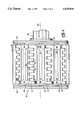
- FIG. 2is a perspective view of the belt and tread drum of the FIG. 1 machine
- FIG. 3is a side view of the belt and tread drum of FIG. 2 depicting the circumference of the drum in its condition of minimum circumference;
- FIG. 4is a view similar to that of FIG. 3 depicting the circumference of the drum in its condition of maximum circumference;
- FIG. 5is a fragmentary side view, shown partly in section, of the FIG. 2 drum illustrating schematically the means by which the circumference of the drum is adjusted;
- FIG. 6is a perspective view of a multi-sectioned arcuate segment of the FIG. 2 drum, shown exploded;
- FIG. 7is a plan view of the sections of the FIG. 6 segment
- FIG. 8is an end elevation view of the sections of the FIG. 6 segment
- FIG. 9is an end view of the sections illustrated in FIG. 8 but drawn to a slightly larger scale and shown in an assembled relationship;
- FIG. 10is a side elevational view of a guide plate of the FIG. 6 segment
- FIG. 11is an end elevational view of a fragment of the FIG. 2 drum showing the relationship of adjacent segments and guide plates when the circumference of the drum is adjusted;
- FIG. 12is a radial cross sectional view of a fragment of the FIG. 2 drum
- FIG. 13is a view similar to that of FIG. 12 of a fragment of a belt and tread drum of the prior art.
- FIG. 14is a side elevation view of a transfer ring embodying various of the feature of the present invention, and shows contracted to a maximum inner diameter.
- FIG. 15is a side elevation view of the transfer ring of FIG. 14 and shown expanded to a maximum inner diameter.
- FIG. 16is a partial view, in perspective, of the multi-sectional segment units of a transfer ring shown expanded to about 30 percent of its maximum inner diameter.
- FIG. 17is a top plan view depicting an alternative embodiment of a multi-sectional segment embodying various features of the invention.
- FIG. 18is an end view of the left hand side section of the segment depicted in FIG. 17.
- FIG. 1a tire building machine 10 including a belt and tread drum 12 within which features of the present invention are embodied, an expander drum 14, and a transfer ring 16.
- a tire building machine 10including a belt and tread drum 12 within which features of the present invention are embodied, an expander drum 14, and a transfer ring 16.
- the making of a vehicle tireis effected in multiple stages.
- the carcass of the tireis formed.
- This carcasscomprises a sheet of polymeric material having embedded reinforcement cords and formed around two bead wires to form the flexible inner carcass of the tire.
- a second stage of the tire- building processinvolves the forming of a belt and tread package on the belt and tread drum 12.
- the carcass formed in the first stageis transferred to an expander drum 14 which contacts the beads of the carcass to form an airtight seal and inflates the carcass so that the outer diameter thereof is slightly less than the inner diameter of the belt and tread package of the tire.
- a transfer ring 16is placed around the belt and tread package, and the belt and tread drum is collapsed so that the package is supported by the transfer ring 16.
- the transfer ring 16then transfers the belt and tread package to the expander drum 14 and positions the package around the outside of the partially inflated carcass which is already in position on the expander 14.
- the carcassis then further inflated to contact the inside of the belt and tread package, and the belt and tread package is subsequently married to the carcass.
- the circumference of the drum 12is capable of expanding to various diameters to accommodate the build up of belt and tread packages for tires of different diameters. Therefore, when tires of various sizes need to be made on a given, or single, drum, the diameter of the circumference of the belt and tread drum must be adjusted accordingly. Additionally, the belt and tread drum must be able to be collapsed from an expanded condition to permit the belt and tread package to be removed for transfer to a subsequent stage of the tire making process.
- FIGS. 2-4there is depicted an embodiment of a belt and tread drum 12 in accordance with the present invention, wherein the bead and tread drum 12 is generally of cylindrical geometry.
- the depicted drum 12includes first and second flat disc-shaped end plates 20 and 22, respectively, and a central body portion, indicated generally by the numeral 24 and which is disposed between the end plates 20 and 22.
- This body portion 24is made up of a plurality of relatively movable components, the sum of whose movements results in controlled and measured change in the outer circumference of the body portion 24 to accommodate the manufacture of tires of various sizes (i.e. tires of different diameters). Selection and control over the maximum circumference of the drum is provided for externally of the drum by means of an adjustment mechanism 26.
- the body portion 24 of the depicted belt and tread drum 12includes a plurality of circumference-defining, multi-sectioned segments 28 whose outer arcuate surfaces collectively define an arc or segment of the outer circumference of the drum 12.
- Each segment 28is joined, as with bolts 34 and 36, to a planar cam element 38 (FIG. 5) having two opposite side ends 40 and 42 which are slidably received in radially-extending slots provided in the inner surfaces 48 and 50 of the opposite end plates 20 and 22.
- the cam element 38mounted in this manner, it is radially movable with respect to the longitudinal centerline 52 of the drum 12.
- each segment 28 of the depicted drum 12includes a first side section 29, a second side section 31 and an intermediate section 33 disposed between the side sections 29 and 31.
- Each side section 29 or 31 of each segment 28is provided with a plurality of slots 54 along one of its longitudinal side margins. Defined between these slots 54 are alternating fingers 56 that are designed to be received within the slots 54 of the side section 29 or 31 of an adjacent segment 28.
- the several segments 28are depicted with the fingers 56 of the side sections thereof being fully received within respective mating slots of adjacent segments 28.
- the circumference of the drum 12is at its minimum value.
- the drum 12is depicted at its maximum expanded circumference with the fingers 56 of the several segments 28 being withdrawn (partially) from the slots 54 of respective adjacent segments 28.
- the drum 12In order to move the segments 28 radially toward and away from the longitudinal axis 52 of the drum 12 and thereby alter the drum circumference, the drum 12 includes adjustment means, generally indicated 55 in FIG. 5, which cooperate with the cam elements 38 so that upon adjustment, the cam elements 38 are slidably moved along the slots of the end plates 20 and 22 between alternative positions.
- adjustment means 55are known in the art so that a detailed description of the adjustment means 55 is not believed to be necessary. Suffice it to say that each cam element 38 includes a contoured cam surface 57 and the adjustment means 55 includes roller cams 59 which are positioned in contact with the cam surfaces 57 of the cam elements 38.
- Each roller cam 59is mounted for movement within the drum 12 along a linear path oriented parallel to the longitudinal axis 52 of the drum 12, and each cam element 38 is maintained in contact with the surface of a corresponding roller cam 59 under the influence of a spring (not shown).
- the roller cams 59are forcibly moved against the corresponding cam element 38 (in a rightwardly direction as viewed in FIG. 5) so that the roller cams 59 roll along the corresponding cam surface 57 and so that the cam element 38 and the segment 28 supported thereby are moved radially outwardly of the drum 12 (and against the force of the spring) to an alternative position.
- roller cams 59are withdrawn in a direction opposite the cam element 38 (in a leftwardly direction as viewed in FIG. 5) so that the cam element 38 (which is continuously maintained in contact with the corresponding roller cams 59) and the segment 28 supported thereby is permitted to move radially inwardly of the drum 12 (under the influence of the spring) to an alternative position.
- each side section 29 or 31extends along almost the entire length of the drum 12 and defines an outer arcuate surface 61 or 63.
- each side section 29 and 31includes a stepped marginal edge opposite the fingers 56 having a lip 62.
- a bore 64Along the end surface of the outermost finger, indicated 56A, of each side section 29 or 31, there is provided a bore 64 whose purpose will become apparent herein, and there is provided in each end of the lip 62 a bore 65 or 65A which is used to hingedly attach the side section 29 or 31 to the intermediate section 33 in a manner described herein.
- each intermediate section 33extends along substantially the entire length of the drum 12 and includes an outer arcuate surface 66. Furthermore, each intermediate section 33 includes a stepped marginal surface extending along the sides thereof and which includes a lip 67. As depicted in FIGS. 7-9, provided along one side of the lip 67 (i.e. the upper surface as shown in FIG. 8) are a pair of internally-threaded openings 70 and 70' used in the hinged attachment of the intermediate section 33 to a corresponding one of the side sections 29 and 31 in a manner described hereinafter. Defined in the outer surface 66 of the intermediate section 33 and adjacent the ends thereof are through-bores 72, 74 for accepting the bolts 34 and 36 (FIG. 3) with which the segment 28 is attached to a corresponding cam element 38, see FIGS. 2, 5, 11, and 12.
- each side section 29 or 31For hingedly securing one end of each side section 29 or 31 to the intermediate section 33 and with reference again to FIG. 6, there is provided a pair of stud members 76 and 76', each having a body 78 and a pin portion 80 projecting from the body 78.
- Each stud member, 76for example, is secured to the intermediate section 33 with screws 82 which extend through the body 78 of the member 76 and are threadably received by the internally-threaded openings 70 and 70' (FIG. 7) of the intermediate member 33.
- each side section 29 or 31is arranged adjacent a corresponding marginal side edge of the intermediate section 33 so that the lip 62 of the side section 29 or 31 overlies the lip 67 of the corresponding marginal edge and so that the bores 65 and 65A provided in an end of each of side sections 29 or 31 pivotally accepts the pin portion 80 of a corresponding stud member 76 and 76'.
- each segment 28also includes guide means 98 for coordinating the movement of the side sections 29 and 31 with those side sections of an adjacent segment 28 as the segments 28 are moved radially of the drum axis 52.
- the guide means 98 of the depicted embodimentincludes a pair of elongated plates 100 each having two opposite ends 102 and 104 and two opposite side faces 106 and 108 extending between the ends 102 and 104.
- each guide plate 100is arcuate in shape so that the curvature of its outer surface, indicated 110, corresponds with that of the outer surfaces 61, 63 and 66 of the segment sections 29, 31 and 33.
- Two through-openings 112 and 114extend between the faces 106 and 108 for receiving the shanks of bolts 116, 118 (FIG. 6) used to attach the plate 100 to a corresponding end of the intermediate section 33.
- a through-bore 120extends between the faces 106, 108 at a location adjacent the plate end 104.
- One end of a pin 122(FIG. 6) is fixed within the through-bore 120, and the other end of the pin 122 is loosely received by the bore 65A provided in the side face of the outermost finger 56A of the side section 29.
- each side section 29 or 31is pivotally attached to the intermediate section 33 for hinged movement relative thereto about a pivot axis 90 or 92 between its position shown in solid lines in FIG. 9 and its position shown in phantom in FIG. 9. Accordingly, the diameter of each bore 65 or 65A is slightly larger than the diameter of the corresponding pin portion 80 or pin 122 accepted thereby.
- each guide plate 100is also provided with an elongated slot 124 which is defined within each guide plate so as to extend substantially linearly along its side face 108.
- the end 125 of the slot 124 situated adjacent the plate end 102is closer to the outer surface 110 of the plate 100 than is the opposite end 127 of the slot 124 thereby orienting the slot at an angle with respect to a radius of the apparatus.
- one end of a pin 126is fixedly received in the outermost finger 56A of each side section 29 or 31 adjacent the tip thereof, and the other end of the pin 126 is loosely received in the slot 124 of a guide plate 100 of an adjacent segment 28.
- the guide platemay be provided with a curved outer surface which is engaged by the pin of an adjacent side section in the nature of a cam and cam follower.
- each pin 126(to which a side section 29 or 31 is secured) slidably moves along its corresponding slot 124 from one end 125 of the slot 124 to the opposite end 127 of the slot 126.
- the side section 29 or 31 of the adjacent segment 38is hingedly moved relative to its intermediate section 33 about the pivot axis 90 or 92 as the intermediate section 33 is moved toward and away from the drum axis 52.
- the side sections 29 and 31 of the one segment 28are hingedly moved by the guide plates 100 of an adjacent segment 28 relative to the intermediate section 33 from, for example, the solid line position shown in FIG. 9 toward the position shown in phantom in FIG. 9.
- the side sections 29 and 31 of the one segment 28are hingedly moved by the guide plates 100 of an adjacent segment 28 relative to the intermediate section 33 from, for example, the FIG. 9 phantom-line position toward the FIG. 9 solid-line position.
- FIG. 12a cross-sectional view of a portion of the drum 12 with its multi-sectioned segments 28 which collectively define a segment of the arc of the drum circumference, e.g. an arc whose segment spans an angle of thirty-six degrees about the drum axis 52. It can be seen in FIG. 12
- transitional regions 130between the outwardmost portions of the arcuate surfaces provided by the sections 29, 31 and 33 and the sections 29 and 31 of an adjacent segment 28 at which the surface of the drum 12 is relatively flat.
- the distance that each of these flat regions or “spots" 130 are spaced from the outermost drum circumferenceis indicated 132.
- FIG. 13a portion of a drum 150 of the prior art having an arcuate segment 152 wherein each segment 152 is comprised of a single section 154 whose arcuate surface generally spans about the same arc (e.g. an arc whose segment spans thirty-six degrees about the longitudinal axis of the drum) as does that of each segment 28 of the FIG. 12 drum.
- the circumferential surface of the drum 150is provided with relatively flat regions, or "spots" 156, of transition between the outermost portions of the surfaces of adjacent segments 152.
- each flat spot 156is spaced from its outermost drum circumference is considerably greater than the distance 132 at which each dip 130 (FIG. 12) is spaced from its outermost drum circumference.
- the flat spots 156 of the FIG. 13 drumare appreciably deeper than those of the FIG. 12 drum, and that the magnitude of this depth is responsible for a large radial runout when a tire is constructed on the FIG. 13 drum at its larger diameter settings, the FIG. 12 drum is preferred over the FIG. 13 drum.
- a tire constructed about the FIG. 12 drumis less likely to be adversely affected by its flat spots and out-of-round condition than is a tire constructed about the FIG. 13 drum, and the FIG. 12 drum is advantageous in this respect.
- the modified drumis provided with a total of thirty surface-defining sections, rather than ten segments, which collectively cooperate to reduce the out-of-round condition of the drum especially at the larger diameter settings.
- Such a thirty-section drum(comparable in construction with that of the drum 12 of FIGS. 1-12) has been built and tested for radial runout.
- This drumhas a circumferential working range of about 60.0 inches to 83.50 inches with an optimum circumference of about 60.0 inches.
- drum 12is for the purpose of illustration and not limitation. It should be recognized that a belt and tread drum embodying features of the present invention could be made with numerous modifications, substitutions, deletions and additions without departing from the scope of the claims as set forth hereinafter.
- each segmentmay comprise only two sections which are hingedly connected as by a hinge rod about a common hinge line.
- FIGS. 17 and 18there is depicted such an alternative embodiment of the multi-sectional segment 28 of the present invention wherein the intermediate section of the alternative segment 28" has substituted therefor a pair of hinge pins 162 and 164 that are fixedly mounted in respective ones of the guide plates 100". These pins project from their respective guide plates inwardly of the segment 28" to pivotally receive thereon pin mounts 166, 168, 170 and 172 which are threaded into respective bores 174, 176, 178 and 180 provided in the side edge of first and second side sections 29" and 31". These side sections are essentially otherwise identical to the side sections 29 and 31 described hereinabove. In this alternative embodiment, as noted, the side sections are hingedly supported by the guide plates.
- one embodiment of the present inventionmay take the form of a transfer ring 200 that includes a circular frame 202 having a central axis 204.
- This frameis made up of an outer ring 206 of "U"-shaped cross section and an inner ring 208 with the inner ring being rotatable within the outer ring. Rotation of the rings relative to one another is provided by piston-cylinder means 210.
- the frameserves as the mounting for a plurality of multi-sectional segments 28'" that are movable radially inwardly and outwardly relative to the central axis.
- each segment 28'"includes an intermediate section 33'" and two flanking side sections 29'" and 31'"
- Each intermediate section of segmentincludes a guide plate 100'" fixedly attached to one of its ends 222 and a further guide plate 100'" fixedly attached to the other of its ends 224.
- each of the side sections 29'" and 31'" of a segment 28'"is hingedly mounted to their respective intermediate section 33'".
- This hinged mounting of the side sections to their respective intermediate section and the interconnection of adjacent side sections of adjacent segmentsserves to hingedly rotate the side sections about their respective hinge mounted axis as the several segments are moved radially inwardly or outwardly with respect to the central axis.
- Each mounting blockincludes first and second guide grooves 234 and 236 respectively.
- a rigid guide rod 237 having one end 238 thereof anchored in a first guide groove 236extends therefrom such that its opposite end 240 is slideably received in the second groove 234' of the guide block 230' of an adjacent segment. As the segments move radially inwardly or outwardly, the end 240 of the guide rod slides within its respective groove 234 thereby maintaining constant relative rotational positioning of the several segments 28'".
- FIGS. 14-16is particularly useful as a transfer ring for grasping a completed belt and tread package after its completion and release from a belt and tread drum by engaging the outer circumference of the package with the inner arcuate surfaces of the segments of the transfer ring.
- this engagement of the "shoes" (i.e segments) of the transfer ring and the outer circumferential surface of the belt and tread packagemust be effected very carefully to avoid developing indentations in the package by the shoes. Such indentations commonly later show up as imperfections in the finished vehicle tire.
Landscapes
- Engineering & Computer Science (AREA)
- Mechanical Engineering (AREA)
- Manufacturing & Machinery (AREA)
- Tyre Moulding (AREA)
Abstract
Description
Claims (12)
Priority Applications (3)
| Application Number | Priority Date | Filing Date | Title |
|---|---|---|---|
| US08/547,381US5635016A (en) | 1995-10-24 | 1995-10-24 | Transfer ring or drum apparatus with adjustable circumference |
| CA002188639ACA2188639C (en) | 1995-10-24 | 1996-10-23 | Apparatus with adjustable circumference |
| US08/739,676US5709768A (en) | 1995-10-24 | 1996-10-29 | Apparatus with adjustable circumference made up of a plurality of interconnected shoes |
Applications Claiming Priority (1)
| Application Number | Priority Date | Filing Date | Title |
|---|---|---|---|
| US08/547,381US5635016A (en) | 1995-10-24 | 1995-10-24 | Transfer ring or drum apparatus with adjustable circumference |
Related Child Applications (1)
| Application Number | Title | Priority Date | Filing Date |
|---|---|---|---|
| US08/739,676Continuation-In-PartUS5709768A (en) | 1995-10-24 | 1996-10-29 | Apparatus with adjustable circumference made up of a plurality of interconnected shoes |
Publications (1)
| Publication Number | Publication Date |
|---|---|
| US5635016Atrue US5635016A (en) | 1997-06-03 |
Family
ID=24184435
Family Applications (1)
| Application Number | Title | Priority Date | Filing Date |
|---|---|---|---|
| US08/547,381Expired - LifetimeUS5635016A (en) | 1995-10-24 | 1995-10-24 | Transfer ring or drum apparatus with adjustable circumference |
Country Status (2)
| Country | Link |
|---|---|
| US (1) | US5635016A (en) |
| CA (1) | CA2188639C (en) |
Cited By (36)
| Publication number | Priority date | Publication date | Assignee | Title |
|---|---|---|---|---|
| US20030051793A1 (en)* | 2001-09-14 | 2003-03-20 | Cavalotti Marie-Laure Benedicte Josette | Cutting segment for a false drum and method of supporting material overlying a slot |
| US6676787B2 (en) | 2001-09-14 | 2004-01-13 | The Goodyear Tire & Rubber Company | False drum with a variable area vacuum-surface |
| US20040239134A1 (en)* | 2003-05-29 | 2004-12-02 | Hisashi Fukazawa | Article gripping device |
| US20050158420A1 (en)* | 2002-02-25 | 2005-07-21 | Shoju Suzuki | Rubber member sticking device |
| US20070037643A1 (en)* | 2005-08-09 | 2007-02-15 | Briesmeister Andrew E | Variable circumference sprocket |
| WO2007074482A1 (en)* | 2005-12-28 | 2007-07-05 | Pirelli Tyre S.P.A. | Method and apparatus for manufacturing pneumatic tyres |
| US20080105358A1 (en)* | 2006-11-08 | 2008-05-08 | Bridgestone Firestone North American Tire, Llc | Chucks and use in processing toroidal structures |
| US20100000658A1 (en)* | 2008-07-02 | 2010-01-07 | Wyko Tire Technology, Inc. | Transfer Ring Having Advantaged Cam Follower-Camming Groove Aspect and Method |
| WO2011159343A1 (en)* | 2010-06-15 | 2011-12-22 | Bps Engineering, Llc | Transfer ring or drum apparatus having adjustable circumference |
| US20120204633A1 (en)* | 2011-02-11 | 2012-08-16 | Bridgestone Americas Tire Operations, Llc | Tire chip and tear test apparatus and method |
| US20120267031A1 (en)* | 2003-11-21 | 2012-10-25 | William David Mawby | Tire manufacturing method for improving the uniformity of a tire |
| US20130168023A1 (en)* | 2009-11-25 | 2013-07-04 | Michelin Recherche Et Technique S.A. | Tire Blank Assembly Device Including Removable Members |
| US8701731B2 (en) | 2008-07-02 | 2014-04-22 | Davian Enterprises, LLC | Transfer ring having advantaged cam follower-camming groove aspect and method |
| US8708017B2 (en) | 2010-12-31 | 2014-04-29 | Bps Engineering, Llc | Assembly for altering the diameter of transfer ring or drum apparatus through a broad range |
| US20140216660A1 (en)* | 2012-08-10 | 2014-08-07 | Davian Enterprises, LLC | Transfer Ring Shoe and Transfer Ring Having Varied Shoe Profile |
| WO2015120379A1 (en)* | 2014-02-07 | 2015-08-13 | Davian Enterprises, LLC | Expandable belt and tread drum with varied curvature segments |
| US20150239190A1 (en)* | 2014-02-27 | 2015-08-27 | The Goodyear Tire & Rubber Company | Transfer ring or drum apparatus with adjustable circumference |
| US9662847B2 (en) | 2005-03-30 | 2017-05-30 | Davian Enterprises, LLC | Tire building drum having sequenced segment expansion |
| CN107405848A (en)* | 2015-03-31 | 2017-11-28 | 倍耐力轮胎股份公司 | For the technique of the tire that constructs wheel of vehicle and expansible assembly drum designed |
| US9855715B2 (en) | 2013-06-07 | 2018-01-02 | Davian Enterprises, LLC | Tire building drum with increased range of movement |
| US10065382B2 (en)* | 2008-04-18 | 2018-09-04 | Pirelli Tyre S.P.A. | Process and apparatus for assembling tyres |
| US10155351B2 (en)* | 2007-06-11 | 2018-12-18 | Pirelli Tyre S.P.A. | Process and apparatus for manufacturing tyres |
| US10189221B2 (en)* | 2012-08-10 | 2019-01-29 | Davian Enterprises, LLC | Transfer ring shoe and transfer ring having varied shoe profile |
| CN109624614A (en)* | 2019-01-21 | 2019-04-16 | 浙江利福德机械有限公司 | A kind of tire construction |
| US10421241B2 (en)* | 2015-01-16 | 2019-09-24 | Compagnie Generale Des Etablissements Michelin | Drum for producing a tire blank |
| WO2020069300A1 (en)* | 2018-09-27 | 2020-04-02 | Davian Enterprises, LLC | Transfer ring with block and rail system |
| WO2020160012A1 (en)* | 2019-01-28 | 2020-08-06 | Davian Enterprises, LLC | Expandable belt and tread drum with reverse offset fingers |
| US10766300B2 (en) | 2017-11-09 | 2020-09-08 | Michael Goren | Expandable and retractable wheel assembly |
| WO2021123530A1 (en)* | 2019-12-20 | 2021-06-24 | Compagnie Generale Des Etablissements Michelin | Machine for the automatic manufacture of pneumatic tyres with a "biased" crown |
| US11230075B2 (en) | 2013-11-26 | 2022-01-25 | Pirelli Tyre S.P.A. | Method and plant for building tyres |
| US11298900B2 (en)* | 2015-12-28 | 2022-04-12 | Pirelli Tyre S.P.A. | Process and plant for building tyres |
| RU2797100C2 (en)* | 2019-01-28 | 2023-05-31 | Дейвиан Энтерпрайзиз, Ллк | Expandable bracket and protector drum with reversibly offset fingers |
| CN116833272A (en)* | 2023-09-01 | 2023-10-03 | 新乡市锦运汽车配件有限公司 | Aluminum profile arc bending device |
| US11993043B2 (en) | 2020-12-03 | 2024-05-28 | Davian Enterprises, LLC | Expandable belt and tread drum with magnetic deck fixing |
| US12083761B2 (en) | 2020-04-22 | 2024-09-10 | Davian Enterprises, LLC | Shoulder assembly for tire building machine |
| US12162234B2 (en) | 2020-05-29 | 2024-12-10 | Davian Enterprises, LLC | Transfer ring shoe and transfer ring with reduced air entrapment features |
Families Citing this family (1)
| Publication number | Priority date | Publication date | Assignee | Title |
|---|---|---|---|---|
| CN107856333B (en)* | 2017-10-30 | 2020-04-17 | 萨驰华辰机械(苏州)有限公司 | Tyre building drum |
Citations (6)
| Publication number | Priority date | Publication date | Assignee | Title |
|---|---|---|---|---|
| US3607558A (en)* | 1966-03-11 | 1971-09-21 | Dunlop Co Ltd | Tire building former having cylindrical and toroidal configurations |
| US3833444A (en)* | 1972-01-19 | 1974-09-03 | Nat Standard Co | Tire building apparatus of building tires |
| US4547251A (en)* | 1983-12-29 | 1985-10-15 | The B. F. Goodrich Company | Adjustable tire building drum |
| US4923554A (en)* | 1987-08-20 | 1990-05-08 | Bridgestone Corporation | Forming drum for building a tire |
| SU1696315A1 (en)* | 1987-10-19 | 1991-12-07 | Всесоюзный Научно-Исследовательский И Конструкторский Институт По Оборудованию Для Шинной Промышленности | Drum for mounting pneumatic tyres |
| US5203947A (en)* | 1991-10-07 | 1993-04-20 | Bridgestone Corporation | Radially expandable tire forming drum |
- 1995
- 1995-10-24USUS08/547,381patent/US5635016A/ennot_activeExpired - Lifetime
- 1996
- 1996-10-23CACA002188639Apatent/CA2188639C/ennot_activeExpired - Fee Related
Patent Citations (6)
| Publication number | Priority date | Publication date | Assignee | Title |
|---|---|---|---|---|
| US3607558A (en)* | 1966-03-11 | 1971-09-21 | Dunlop Co Ltd | Tire building former having cylindrical and toroidal configurations |
| US3833444A (en)* | 1972-01-19 | 1974-09-03 | Nat Standard Co | Tire building apparatus of building tires |
| US4547251A (en)* | 1983-12-29 | 1985-10-15 | The B. F. Goodrich Company | Adjustable tire building drum |
| US4923554A (en)* | 1987-08-20 | 1990-05-08 | Bridgestone Corporation | Forming drum for building a tire |
| SU1696315A1 (en)* | 1987-10-19 | 1991-12-07 | Всесоюзный Научно-Исследовательский И Конструкторский Институт По Оборудованию Для Шинной Промышленности | Drum for mounting pneumatic tyres |
| US5203947A (en)* | 1991-10-07 | 1993-04-20 | Bridgestone Corporation | Radially expandable tire forming drum |
Cited By (82)
| Publication number | Priority date | Publication date | Assignee | Title |
|---|---|---|---|---|
| US7008494B2 (en) | 2001-09-14 | 2006-03-07 | The Goodyear Tire & Rubber Co. | Cutting segment for a false drum and method of supporting material overlying a slot |
| US6676787B2 (en) | 2001-09-14 | 2004-01-13 | The Goodyear Tire & Rubber Company | False drum with a variable area vacuum-surface |
| US20040089422A1 (en)* | 2001-09-14 | 2004-05-13 | Cavalotti Marie-Laure Benedicte Josette | Fals drum with a variable area vacuum-surface |
| US6736932B2 (en) | 2001-09-14 | 2004-05-18 | The Goodyear Tire & Rubber Company | Cutting segment for a false drum |
| US20040140043A1 (en)* | 2001-09-14 | 2004-07-22 | Cavalotti Marie-Laure Benedicte Josette | Cutting segment for a false drum and method of supporting material overlying a slot |
| US20030051793A1 (en)* | 2001-09-14 | 2003-03-20 | Cavalotti Marie-Laure Benedicte Josette | Cutting segment for a false drum and method of supporting material overlying a slot |
| US7037404B2 (en) | 2001-09-14 | 2006-05-02 | The Goodyear Tire & Rubber Company | False drum with a variable area vacuum-surface |
| US20050158420A1 (en)* | 2002-02-25 | 2005-07-21 | Shoju Suzuki | Rubber member sticking device |
| US7578897B2 (en)* | 2002-02-28 | 2009-08-25 | Bridgestone Corporation | Rubber member sticking device |
| CN1572478B (en)* | 2003-05-29 | 2010-09-08 | 横滨橡胶株式会社 | Article gripping device |
| US7370897B2 (en)* | 2003-05-29 | 2008-05-13 | The Yokohama Rubber Co., Ltd. | Article gripping device |
| US20040239134A1 (en)* | 2003-05-29 | 2004-12-02 | Hisashi Fukazawa | Article gripping device |
| US20120267031A1 (en)* | 2003-11-21 | 2012-10-25 | William David Mawby | Tire manufacturing method for improving the uniformity of a tire |
| US9662847B2 (en) | 2005-03-30 | 2017-05-30 | Davian Enterprises, LLC | Tire building drum having sequenced segment expansion |
| US20070037643A1 (en)* | 2005-08-09 | 2007-02-15 | Briesmeister Andrew E | Variable circumference sprocket |
| US20110126963A1 (en)* | 2005-12-28 | 2011-06-02 | Gianni Mancini | Method and Apparatus for Manufacturing Pneumatic Tyres |
| US9415556B2 (en) | 2005-12-28 | 2016-08-16 | Pirelli Tyre S.P.A. | Method and apparatus for manufacturing pneumatic tyres |
| WO2007074482A1 (en)* | 2005-12-28 | 2007-07-05 | Pirelli Tyre S.P.A. | Method and apparatus for manufacturing pneumatic tyres |
| US8714222B2 (en) | 2005-12-28 | 2014-05-06 | Pirelli Tyre S.P.A. | Method and apparatus for manufacturing pneumatic tyres |
| US20080105358A1 (en)* | 2006-11-08 | 2008-05-08 | Bridgestone Firestone North American Tire, Llc | Chucks and use in processing toroidal structures |
| US20110119918A1 (en)* | 2006-11-08 | 2011-05-26 | Bridgestone Americas Tire Operations, Llc | Chucks and use in processing toroidal structures |
| US7896048B2 (en) | 2006-11-08 | 2011-03-01 | Bridgestone Americas Tire Operations, Llc | Chucks and use in processing toroidal structures |
| US8236117B2 (en) | 2006-11-08 | 2012-08-07 | Bridgestone Americas Tire Operations, Llc | Chucks and use in processing toroidal structures |
| US10155351B2 (en)* | 2007-06-11 | 2018-12-18 | Pirelli Tyre S.P.A. | Process and apparatus for manufacturing tyres |
| US10065382B2 (en)* | 2008-04-18 | 2018-09-04 | Pirelli Tyre S.P.A. | Process and apparatus for assembling tyres |
| US8701731B2 (en) | 2008-07-02 | 2014-04-22 | Davian Enterprises, LLC | Transfer ring having advantaged cam follower-camming groove aspect and method |
| US8091602B2 (en) | 2008-07-02 | 2012-01-10 | Davian Enterprises, LLC | Transfer ring having advantaged cam follower-camming groove aspect and method |
| US20100000658A1 (en)* | 2008-07-02 | 2010-01-07 | Wyko Tire Technology, Inc. | Transfer Ring Having Advantaged Cam Follower-Camming Groove Aspect and Method |
| US20130168023A1 (en)* | 2009-11-25 | 2013-07-04 | Michelin Recherche Et Technique S.A. | Tire Blank Assembly Device Including Removable Members |
| US9044908B2 (en)* | 2009-11-25 | 2015-06-02 | Compagnie Generale Des Etablissements Michelin | Tire blank assembly device including removable members |
| DE112011102041T5 (en) | 2010-06-15 | 2013-05-02 | Bps Engineering, Llc | Transfer ring or drum device with adjustable circumference |
| US8602078B2 (en) | 2010-06-15 | 2013-12-10 | Bps Engineering, Llc | Transfer ring or drum apparatus having adjustable circumference |
| WO2011159343A1 (en)* | 2010-06-15 | 2011-12-22 | Bps Engineering, Llc | Transfer ring or drum apparatus having adjustable circumference |
| US8708017B2 (en) | 2010-12-31 | 2014-04-29 | Bps Engineering, Llc | Assembly for altering the diameter of transfer ring or drum apparatus through a broad range |
| US8347703B2 (en)* | 2011-02-11 | 2013-01-08 | Bridgestone Americas Tire Operations, Llc | Tire chip and tear test apparatus and method |
| US20120204633A1 (en)* | 2011-02-11 | 2012-08-16 | Bridgestone Americas Tire Operations, Llc | Tire chip and tear test apparatus and method |
| CN104995016A (en)* | 2012-08-10 | 2015-10-21 | 达维阶企业有限责任公司 | Transfer ring shoe and transfer ring having varied shoe profile |
| US10189221B2 (en)* | 2012-08-10 | 2019-01-29 | Davian Enterprises, LLC | Transfer ring shoe and transfer ring having varied shoe profile |
| US20140216660A1 (en)* | 2012-08-10 | 2014-08-07 | Davian Enterprises, LLC | Transfer Ring Shoe and Transfer Ring Having Varied Shoe Profile |
| WO2014026184A3 (en)* | 2012-08-10 | 2015-07-16 | Davian Enterprises, LLC | Transfer ring shoe with varied profile |
| US9855715B2 (en) | 2013-06-07 | 2018-01-02 | Davian Enterprises, LLC | Tire building drum with increased range of movement |
| US10328647B2 (en) | 2013-08-12 | 2019-06-25 | Davian Enterprises, LLC | Expandable belt and tread drum having irregular segment profiles |
| US11230075B2 (en) | 2013-11-26 | 2022-01-25 | Pirelli Tyre S.P.A. | Method and plant for building tyres |
| CN106103066A (en)* | 2014-02-07 | 2016-11-09 | 达维阶企业有限责任公司 | There is inflatable belt and the tread drum of the section of different curvature |
| CN106103066B (en)* | 2014-02-07 | 2019-10-18 | 达维阶企业有限责任公司 | The inflatable banding and tread drum of section with different curvature |
| EP3102399A4 (en)* | 2014-02-07 | 2017-09-13 | Davian Enterprises, LLC | Expandable belt and tread drum with varied curvature segments |
| EP3102400A4 (en)* | 2014-02-07 | 2017-10-18 | Davian Enterprises, LLC | Expandable drum having irregular segment profiles |
| CN106132677A (en)* | 2014-02-07 | 2016-11-16 | 达维阶企业有限责任公司 | There is the inflatable drum of irregular section profile |
| RU2684094C2 (en)* | 2014-02-07 | 2019-04-03 | Дейвиан Энтерпрайзиз, Ллк | Expandable belt and tread drum with varied curvature segments |
| KR20160120305A (en)* | 2014-02-07 | 2016-10-17 | 다비안 엔터프라이즈, 엘엘씨 | Expandable belt and tread drum with varied curvature segments |
| WO2015120379A1 (en)* | 2014-02-07 | 2015-08-13 | Davian Enterprises, LLC | Expandable belt and tread drum with varied curvature segments |
| WO2015126650A1 (en)* | 2014-02-07 | 2015-08-27 | Davian Enterprises, LLC | Expandable drum having irregular segment profiles |
| US10040262B2 (en) | 2014-02-07 | 2018-08-07 | Davian Enterprises, LLC | Expandable belt and tread drum with varied curvature segments |
| US20150239190A1 (en)* | 2014-02-27 | 2015-08-27 | The Goodyear Tire & Rubber Company | Transfer ring or drum apparatus with adjustable circumference |
| EP2913182A1 (en)* | 2014-02-27 | 2015-09-02 | The Goodyear Tire & Rubber Company | Transfer ring or drum apparatus with adjustable circumference |
| CN104875408A (en)* | 2014-02-27 | 2015-09-02 | 固特异轮胎和橡胶公司 | Transfer ring or drum apparatus with adjustable circumference |
| US10421241B2 (en)* | 2015-01-16 | 2019-09-24 | Compagnie Generale Des Etablissements Michelin | Drum for producing a tire blank |
| KR20170138398A (en)* | 2015-03-31 | 2017-12-15 | 피렐리 타이어 소시에떼 퍼 아찌오니 | Patent application title: EXPANSIONABLE FORMING DRUM AND METHOD FOR MANUFACTURING TIRES FOR VEHICLE WHEEL |
| CN107405848A (en)* | 2015-03-31 | 2017-11-28 | 倍耐力轮胎股份公司 | For the technique of the tire that constructs wheel of vehicle and expansible assembly drum designed |
| US20180178468A1 (en)* | 2015-03-31 | 2018-06-28 | Pirelli Tyre S.P.A. | Process and expandable forming drum for building tyres for vehicle wheels |
| JP2018512297A (en)* | 2015-03-31 | 2018-05-17 | ピレリ・タイヤ・ソチエタ・ペル・アツィオーニ | Process and expandable forming drum for building tires for vehicle wheels |
| KR102416186B1 (en) | 2015-03-31 | 2022-07-04 | 피렐리 타이어 소시에떼 퍼 아찌오니 | Inflatable forming drum and manufacturing method for manufacturing tire for vehicle wheel |
| US10661518B2 (en)* | 2015-03-31 | 2020-05-26 | Pirelli Tyre S.P.A. | Process and expandable forming drum for building tyres for vehicle wheels |
| US11267213B2 (en)* | 2015-03-31 | 2022-03-08 | Pirelli Tyre S.P.A. | Process and expandable forming drum for building tyres for vehicle wheels |
| CN107405848B (en)* | 2015-03-31 | 2020-08-25 | 倍耐力轮胎股份公司 | Process and expandable forming drum for building tires for vehicle wheels |
| US11298900B2 (en)* | 2015-12-28 | 2022-04-12 | Pirelli Tyre S.P.A. | Process and plant for building tyres |
| US10766300B2 (en) | 2017-11-09 | 2020-09-08 | Michael Goren | Expandable and retractable wheel assembly |
| US11358356B2 (en) | 2018-09-27 | 2022-06-14 | Davian Enterprises, LLC | Transfer ring with block and rail system |
| WO2020069300A1 (en)* | 2018-09-27 | 2020-04-02 | Davian Enterprises, LLC | Transfer ring with block and rail system |
| CN109624614B (en)* | 2019-01-21 | 2024-04-02 | 浙江利福德机械有限公司 | Tire structure |
| CN109624614A (en)* | 2019-01-21 | 2019-04-16 | 浙江利福德机械有限公司 | A kind of tire construction |
| RU2797100C2 (en)* | 2019-01-28 | 2023-05-31 | Дейвиан Энтерпрайзиз, Ллк | Expandable bracket and protector drum with reversibly offset fingers |
| WO2020160012A1 (en)* | 2019-01-28 | 2020-08-06 | Davian Enterprises, LLC | Expandable belt and tread drum with reverse offset fingers |
| US11548251B2 (en) | 2019-01-28 | 2023-01-10 | Davian Enterprises, LLC | Expandable belt and tread drum with reverse offset fingers |
| WO2021123530A1 (en)* | 2019-12-20 | 2021-06-24 | Compagnie Generale Des Etablissements Michelin | Machine for the automatic manufacture of pneumatic tyres with a "biased" crown |
| FR3105081A1 (en)* | 2019-12-20 | 2021-06-25 | Compagnie Generale Des Etablissements Michelin | AUTOMATIC MANUFACTURING MACHINE FOR PNEUMATIC BANDAGES WITH A "POLARIZED" SUMMIT |
| US12005661B2 (en) | 2019-12-20 | 2024-06-11 | Compagnie Generale Des Etablissements Michelin | Machine for the automatic manufacture of pneumatic tires with a “biased” crown |
| US12083761B2 (en) | 2020-04-22 | 2024-09-10 | Davian Enterprises, LLC | Shoulder assembly for tire building machine |
| US12162234B2 (en) | 2020-05-29 | 2024-12-10 | Davian Enterprises, LLC | Transfer ring shoe and transfer ring with reduced air entrapment features |
| US11993043B2 (en) | 2020-12-03 | 2024-05-28 | Davian Enterprises, LLC | Expandable belt and tread drum with magnetic deck fixing |
| CN116833272A (en)* | 2023-09-01 | 2023-10-03 | 新乡市锦运汽车配件有限公司 | Aluminum profile arc bending device |
| CN116833272B (en)* | 2023-09-01 | 2023-11-17 | 新乡市锦运汽车配件有限公司 | Aluminum profile arc bending device |
Also Published As
| Publication number | Publication date |
|---|---|
| CA2188639A1 (en) | 1997-04-25 |
| CA2188639C (en) | 2005-05-24 |
Similar Documents
| Publication | Publication Date | Title |
|---|---|---|
| US5635016A (en) | Transfer ring or drum apparatus with adjustable circumference | |
| EP2913182A1 (en) | Transfer ring or drum apparatus with adjustable circumference | |
| US5709768A (en) | Apparatus with adjustable circumference made up of a plurality of interconnected shoes | |
| US20120256434A1 (en) | Transfer Ring Having Advantaged Cam Follower-Camming Groove Aspect and Method | |
| EP1674248B1 (en) | High crown single stage tire building drum | |
| EP3135466B1 (en) | Radially expandable drum | |
| EP1295702B1 (en) | Tire building drum having independently expandable center and end sections | |
| EP1674249B1 (en) | A method of making a tire using a high crown single stage tire building drum | |
| US20100000658A1 (en) | Transfer Ring Having Advantaged Cam Follower-Camming Groove Aspect and Method | |
| US8261800B2 (en) | Process and apparatus for manufacturing a pneumatic tyre | |
| EP3102399B1 (en) | Expandable belt and tread drum with varied curvature segments | |
| US8602078B2 (en) | Transfer ring or drum apparatus having adjustable circumference | |
| EP2698244B1 (en) | Sleeveless tire building drum with interchangeable width elements | |
| US5464489A (en) | Method for manufacturing a green radial tire using a transfer unit that is movable during pressing | |
| WO2001068356A1 (en) | Tyre building drum provided with a turn-up device | |
| CN113518705A (en) | Expandable belt and tread drum with reverse biased fingers | |
| GB2031818A (en) | Process and apparatus for manufacturing radial tyres | |
| US20030024626A1 (en) | Method and apparatus for tire carcass positioning on a drum | |
| US3536566A (en) | Tire building apparatus | |
| US20180272642A1 (en) | Belt drum device | |
| US6491081B2 (en) | Method of manufacturing radial tire having wound band | |
| US5207849A (en) | Method and device for stitching multilayer products of green elastomeric material | |
| EP0544154B1 (en) | Bead support system for use during tire manufacture | |
| US4584049A (en) | Radial tire forming blank supply apparatus | |
| US20090165929A1 (en) | Process and apparatus for manufacturing a pneumatic tyre |
Legal Events
| Date | Code | Title | Description |
|---|---|---|---|
| AS | Assignment | Owner name:WYKO, INC., TENNESSEE Free format text:ASSIGNMENT OF ASSIGNORS INTEREST;ASSIGNOR:BYERLEY, MARK S.;REEL/FRAME:007768/0522 Effective date:19951023 | |
| FEPP | Fee payment procedure | Free format text:PAYOR NUMBER ASSIGNED (ORIGINAL EVENT CODE: ASPN); ENTITY STATUS OF PATENT OWNER: LARGE ENTITY | |
| FPAY | Fee payment | Year of fee payment:4 | |
| REMI | Maintenance fee reminder mailed | ||
| LAPS | Lapse for failure to pay maintenance fees | ||
| REIN | Reinstatement after maintenance fee payment confirmed | ||
| LAPS | Lapse for failure to pay maintenance fees | Free format text:PATENT EXPIRED FOR FAILURE TO PAY MAINTENANCE FEES (ORIGINAL EVENT CODE: EXP.); ENTITY STATUS OF PATENT OWNER: LARGE ENTITY | |
| FP | Lapsed due to failure to pay maintenance fee | Effective date:20050603 | |
| FEPP | Fee payment procedure | Free format text:PETITION RELATED TO MAINTENANCE FEES FILED (ORIGINAL EVENT CODE: PMFP); ENTITY STATUS OF PATENT OWNER: LARGE ENTITY | |
| FEPP | Fee payment procedure | Free format text:PETITION RELATED TO MAINTENANCE FEES FILED (ORIGINAL EVENT CODE: PMFP); ENTITY STATUS OF PATENT OWNER: LARGE ENTITY | |
| FEPP | Fee payment procedure | Free format text:PETITION RELATED TO MAINTENANCE FEES DISMISSED (ORIGINAL EVENT CODE: PMFS); ENTITY STATUS OF PATENT OWNER: LARGE ENTITY | |
| FPAY | Fee payment | Year of fee payment:12 Year of fee payment:8 | |
| SULP | Surcharge for late payment | ||
| AS | Assignment | Owner name:DAVIAN ENTERPRISES, LLC, TENNESSEE Free format text:NUNC PRO TUNC ASSIGNMENT;ASSIGNOR:WYKO, INC., D/B/A WYKO TIRE TECHNOLOGY, INC.;REEL/FRAME:026973/0650 Effective date:20110819 | |
| FEPP | Fee payment procedure | Free format text:PETITION RELATED TO MAINTENANCE FEES GRANTED (ORIGINAL EVENT CODE: PMFG); ENTITY STATUS OF PATENT OWNER: LARGE ENTITY | |
| PRDP | Patent reinstated due to the acceptance of a late maintenance fee | Effective date:20120921 | |
| STCF | Information on status: patent grant | Free format text:PATENTED CASE |