US5634921A - Method and apparatus for modifications of visual acuity by thermal means - Google Patents
Method and apparatus for modifications of visual acuity by thermal meansDownload PDFInfo
- Publication number
- US5634921A US5634921AUS08/488,829US48882995AUS5634921AUS 5634921 AUS5634921 AUS 5634921AUS 48882995 AUS48882995 AUS 48882995AUS 5634921 AUS5634921 AUS 5634921A
- Authority
- US
- United States
- Prior art keywords
- cornea
- tip
- probe
- power
- electrode
- Prior art date
- Legal status (The legal status is an assumption and is not a legal conclusion. Google has not performed a legal analysis and makes no representation as to the accuracy of the status listed.)
- Expired - Lifetime
Links
Images


Classifications
- A—HUMAN NECESSITIES
- A61—MEDICAL OR VETERINARY SCIENCE; HYGIENE
- A61F—FILTERS IMPLANTABLE INTO BLOOD VESSELS; PROSTHESES; DEVICES PROVIDING PATENCY TO, OR PREVENTING COLLAPSING OF, TUBULAR STRUCTURES OF THE BODY, e.g. STENTS; ORTHOPAEDIC, NURSING OR CONTRACEPTIVE DEVICES; FOMENTATION; TREATMENT OR PROTECTION OF EYES OR EARS; BANDAGES, DRESSINGS OR ABSORBENT PADS; FIRST-AID KITS
- A61F9/00—Methods or devices for treatment of the eyes; Devices for putting in contact-lenses; Devices to correct squinting; Apparatus to guide the blind; Protective devices for the eyes, carried on the body or in the hand
- A61F9/007—Methods or devices for eye surgery
- A61F9/008—Methods or devices for eye surgery using laser
- A—HUMAN NECESSITIES
- A61—MEDICAL OR VETERINARY SCIENCE; HYGIENE
- A61N—ELECTROTHERAPY; MAGNETOTHERAPY; RADIATION THERAPY; ULTRASOUND THERAPY
- A61N5/00—Radiation therapy
- A61N5/06—Radiation therapy using light
- A—HUMAN NECESSITIES
- A61—MEDICAL OR VETERINARY SCIENCE; HYGIENE
- A61B—DIAGNOSIS; SURGERY; IDENTIFICATION
- A61B18/00—Surgical instruments, devices or methods for transferring non-mechanical forms of energy to or from the body
- A61B18/04—Surgical instruments, devices or methods for transferring non-mechanical forms of energy to or from the body by heating
- A61B18/12—Surgical instruments, devices or methods for transferring non-mechanical forms of energy to or from the body by heating by passing a current through the tissue to be heated, e.g. high-frequency current
- A61B18/14—Probes or electrodes therefor
- A—HUMAN NECESSITIES
- A61—MEDICAL OR VETERINARY SCIENCE; HYGIENE
- A61F—FILTERS IMPLANTABLE INTO BLOOD VESSELS; PROSTHESES; DEVICES PROVIDING PATENCY TO, OR PREVENTING COLLAPSING OF, TUBULAR STRUCTURES OF THE BODY, e.g. STENTS; ORTHOPAEDIC, NURSING OR CONTRACEPTIVE DEVICES; FOMENTATION; TREATMENT OR PROTECTION OF EYES OR EARS; BANDAGES, DRESSINGS OR ABSORBENT PADS; FIRST-AID KITS
- A61F9/00—Methods or devices for treatment of the eyes; Devices for putting in contact-lenses; Devices to correct squinting; Apparatus to guide the blind; Protective devices for the eyes, carried on the body or in the hand
- A61F9/007—Methods or devices for eye surgery
- A61F9/008—Methods or devices for eye surgery using laser
- A61F9/00821—Methods or devices for eye surgery using laser for coagulation
- A—HUMAN NECESSITIES
- A61—MEDICAL OR VETERINARY SCIENCE; HYGIENE
- A61F—FILTERS IMPLANTABLE INTO BLOOD VESSELS; PROSTHESES; DEVICES PROVIDING PATENCY TO, OR PREVENTING COLLAPSING OF, TUBULAR STRUCTURES OF THE BODY, e.g. STENTS; ORTHOPAEDIC, NURSING OR CONTRACEPTIVE DEVICES; FOMENTATION; TREATMENT OR PROTECTION OF EYES OR EARS; BANDAGES, DRESSINGS OR ABSORBENT PADS; FIRST-AID KITS
- A61F9/00—Methods or devices for treatment of the eyes; Devices for putting in contact-lenses; Devices to correct squinting; Apparatus to guide the blind; Protective devices for the eyes, carried on the body or in the hand
- A61F9/007—Methods or devices for eye surgery
- A61F9/013—Instruments for compensation of ocular refraction ; Instruments for use in cornea removal, for reshaping or performing incisions in the cornea
- A61F9/0133—Knives or scalpels specially adapted therefor
- A—HUMAN NECESSITIES
- A61—MEDICAL OR VETERINARY SCIENCE; HYGIENE
- A61B—DIAGNOSIS; SURGERY; IDENTIFICATION
- A61B18/00—Surgical instruments, devices or methods for transferring non-mechanical forms of energy to or from the body
- A61B18/18—Surgical instruments, devices or methods for transferring non-mechanical forms of energy to or from the body by applying electromagnetic radiation, e.g. microwaves
- A61B18/1815—Surgical instruments, devices or methods for transferring non-mechanical forms of energy to or from the body by applying electromagnetic radiation, e.g. microwaves using microwaves
- A—HUMAN NECESSITIES
- A61—MEDICAL OR VETERINARY SCIENCE; HYGIENE
- A61B—DIAGNOSIS; SURGERY; IDENTIFICATION
- A61B18/00—Surgical instruments, devices or methods for transferring non-mechanical forms of energy to or from the body
- A61B2018/00053—Mechanical features of the instrument of device
- A61B2018/00172—Connectors and adapters therefor
- A61B2018/00178—Electrical connectors
- A—HUMAN NECESSITIES
- A61—MEDICAL OR VETERINARY SCIENCE; HYGIENE
- A61B—DIAGNOSIS; SURGERY; IDENTIFICATION
- A61B18/00—Surgical instruments, devices or methods for transferring non-mechanical forms of energy to or from the body
- A61B2018/00636—Sensing and controlling the application of energy
- A61B2018/00696—Controlled or regulated parameters
- A61B2018/00761—Duration
- A—HUMAN NECESSITIES
- A61—MEDICAL OR VETERINARY SCIENCE; HYGIENE
- A61B—DIAGNOSIS; SURGERY; IDENTIFICATION
- A61B18/00—Surgical instruments, devices or methods for transferring non-mechanical forms of energy to or from the body
- A61B2018/00636—Sensing and controlling the application of energy
- A61B2018/00773—Sensed parameters
- A61B2018/00886—Duration
- A—HUMAN NECESSITIES
- A61—MEDICAL OR VETERINARY SCIENCE; HYGIENE
- A61B—DIAGNOSIS; SURGERY; IDENTIFICATION
- A61B18/00—Surgical instruments, devices or methods for transferring non-mechanical forms of energy to or from the body
- A61B2018/00988—Means for storing information, e.g. calibration constants, or for preventing excessive use, e.g. usage, service life counter
- A—HUMAN NECESSITIES
- A61—MEDICAL OR VETERINARY SCIENCE; HYGIENE
- A61B—DIAGNOSIS; SURGERY; IDENTIFICATION
- A61B18/00—Surgical instruments, devices or methods for transferring non-mechanical forms of energy to or from the body
- A61B18/04—Surgical instruments, devices or methods for transferring non-mechanical forms of energy to or from the body by heating
- A61B18/12—Surgical instruments, devices or methods for transferring non-mechanical forms of energy to or from the body by heating by passing a current through the tissue to be heated, e.g. high-frequency current
- A61B18/14—Probes or electrodes therefor
- A61B2018/1405—Electrodes having a specific shape
- A61B2018/1425—Needle
- A61B2018/143—Needle multiple needles
- A—HUMAN NECESSITIES
- A61—MEDICAL OR VETERINARY SCIENCE; HYGIENE
- A61B—DIAGNOSIS; SURGERY; IDENTIFICATION
- A61B18/00—Surgical instruments, devices or methods for transferring non-mechanical forms of energy to or from the body
- A61B18/04—Surgical instruments, devices or methods for transferring non-mechanical forms of energy to or from the body by heating
- A61B18/12—Surgical instruments, devices or methods for transferring non-mechanical forms of energy to or from the body by heating by passing a current through the tissue to be heated, e.g. high-frequency current
- A61B18/14—Probes or electrodes therefor
- A61B2018/1475—Electrodes retractable in or deployable from a housing
- A—HUMAN NECESSITIES
- A61—MEDICAL OR VETERINARY SCIENCE; HYGIENE
- A61B—DIAGNOSIS; SURGERY; IDENTIFICATION
- A61B90/00—Instruments, implements or accessories specially adapted for surgery or diagnosis and not covered by any of the groups A61B1/00 - A61B50/00, e.g. for luxation treatment or for protecting wound edges
- A61B90/03—Automatic limiting or abutting means, e.g. for safety
- A61B2090/033—Abutting means, stops, e.g. abutting on tissue or skin
- A61B2090/036—Abutting means, stops, e.g. abutting on tissue or skin abutting on tissue or skin
- A—HUMAN NECESSITIES
- A61—MEDICAL OR VETERINARY SCIENCE; HYGIENE
- A61F—FILTERS IMPLANTABLE INTO BLOOD VESSELS; PROSTHESES; DEVICES PROVIDING PATENCY TO, OR PREVENTING COLLAPSING OF, TUBULAR STRUCTURES OF THE BODY, e.g. STENTS; ORTHOPAEDIC, NURSING OR CONTRACEPTIVE DEVICES; FOMENTATION; TREATMENT OR PROTECTION OF EYES OR EARS; BANDAGES, DRESSINGS OR ABSORBENT PADS; FIRST-AID KITS
- A61F9/00—Methods or devices for treatment of the eyes; Devices for putting in contact-lenses; Devices to correct squinting; Apparatus to guide the blind; Protective devices for the eyes, carried on the body or in the hand
- A61F2009/0035—Devices for immobilising a patient's head with respect to the instrument
- A61F2009/0043—Devices for immobilising a patient's head with respect to the instrument by supporting the instrument on the patient's head, e.g. head bands
- A61F2009/0052—Devices for immobilising a patient's head with respect to the instrument by supporting the instrument on the patient's head, e.g. head bands the instrument being supported on the patient's eye
- A—HUMAN NECESSITIES
- A61—MEDICAL OR VETERINARY SCIENCE; HYGIENE
- A61F—FILTERS IMPLANTABLE INTO BLOOD VESSELS; PROSTHESES; DEVICES PROVIDING PATENCY TO, OR PREVENTING COLLAPSING OF, TUBULAR STRUCTURES OF THE BODY, e.g. STENTS; ORTHOPAEDIC, NURSING OR CONTRACEPTIVE DEVICES; FOMENTATION; TREATMENT OR PROTECTION OF EYES OR EARS; BANDAGES, DRESSINGS OR ABSORBENT PADS; FIRST-AID KITS
- A61F9/00—Methods or devices for treatment of the eyes; Devices for putting in contact-lenses; Devices to correct squinting; Apparatus to guide the blind; Protective devices for the eyes, carried on the body or in the hand
- A61F9/007—Methods or devices for eye surgery
- A61F9/008—Methods or devices for eye surgery using laser
- A61F2009/00844—Feedback systems
- A—HUMAN NECESSITIES
- A61—MEDICAL OR VETERINARY SCIENCE; HYGIENE
- A61F—FILTERS IMPLANTABLE INTO BLOOD VESSELS; PROSTHESES; DEVICES PROVIDING PATENCY TO, OR PREVENTING COLLAPSING OF, TUBULAR STRUCTURES OF THE BODY, e.g. STENTS; ORTHOPAEDIC, NURSING OR CONTRACEPTIVE DEVICES; FOMENTATION; TREATMENT OR PROTECTION OF EYES OR EARS; BANDAGES, DRESSINGS OR ABSORBENT PADS; FIRST-AID KITS
- A61F9/00—Methods or devices for treatment of the eyes; Devices for putting in contact-lenses; Devices to correct squinting; Apparatus to guide the blind; Protective devices for the eyes, carried on the body or in the hand
- A61F9/007—Methods or devices for eye surgery
- A61F9/008—Methods or devices for eye surgery using laser
- A61F2009/00853—Laser thermal keratoplasty or radial keratotomy
- A—HUMAN NECESSITIES
- A61—MEDICAL OR VETERINARY SCIENCE; HYGIENE
- A61F—FILTERS IMPLANTABLE INTO BLOOD VESSELS; PROSTHESES; DEVICES PROVIDING PATENCY TO, OR PREVENTING COLLAPSING OF, TUBULAR STRUCTURES OF THE BODY, e.g. STENTS; ORTHOPAEDIC, NURSING OR CONTRACEPTIVE DEVICES; FOMENTATION; TREATMENT OR PROTECTION OF EYES OR EARS; BANDAGES, DRESSINGS OR ABSORBENT PADS; FIRST-AID KITS
- A61F9/00—Methods or devices for treatment of the eyes; Devices for putting in contact-lenses; Devices to correct squinting; Apparatus to guide the blind; Protective devices for the eyes, carried on the body or in the hand
- A61F9/007—Methods or devices for eye surgery
- A61F9/008—Methods or devices for eye surgery using laser
- A61F2009/00861—Methods or devices for eye surgery using laser adapted for treatment at a particular location
- A61F2009/00872—Cornea
- A—HUMAN NECESSITIES
- A61—MEDICAL OR VETERINARY SCIENCE; HYGIENE
- A61F—FILTERS IMPLANTABLE INTO BLOOD VESSELS; PROSTHESES; DEVICES PROVIDING PATENCY TO, OR PREVENTING COLLAPSING OF, TUBULAR STRUCTURES OF THE BODY, e.g. STENTS; ORTHOPAEDIC, NURSING OR CONTRACEPTIVE DEVICES; FOMENTATION; TREATMENT OR PROTECTION OF EYES OR EARS; BANDAGES, DRESSINGS OR ABSORBENT PADS; FIRST-AID KITS
- A61F9/00—Methods or devices for treatment of the eyes; Devices for putting in contact-lenses; Devices to correct squinting; Apparatus to guide the blind; Protective devices for the eyes, carried on the body or in the hand
- A61F9/007—Methods or devices for eye surgery
- A61F9/0079—Methods or devices for eye surgery using non-laser electromagnetic radiation, e.g. non-coherent light or microwaves
Definitions
- the present inventionrelates to a thermokeratoplasty probe that is placed into direct contact with the outer surface of the cornea.
- myopic conditionscan be corrected by cutting a number of small incisions in the corneal membrane.
- the incisionsallow the corneal membrane to relax and increase the radius of the cornea.
- the incisionsare typically created with either a laser or a precision knife.
- the procedure for creating incisions to correct myopic defectsis commonly referred to as radial keratotomy and is well known in the art.
- radial keratotomyare only effective in correcting myopia. Radial keratotomy cannot be used to correct an eye condition such as hyperopia. Additionally, keratotomy has limited use in reducing or correcting an astigmatism.
- the cornea of a patient with hyperopiais relatively flat (large spherical radius). A flat cornea creates a lens system which does not correctly focus the viewed image onto the retina of the eye. Hyperopia can be corrected by reshaping the eye to decrease the spherical radius of the cornea. It has been found that hyperopia can be corrected by heating and denaturing local regions of the cornea. The denatured tissue contracts and changes the shape of the cornea and corrects the optical characteristics of the eye. The procedure of heating the corneal membrane to correct a patient's vision is commonly referred to as thermokeratoplasty.
- thermokeratoplastic techniqueswhich utilize a laser to heat the cornea.
- the energy of the lasergenerates localized heat within the corneal stroma through photonic absorption.
- the heated areas of the stromathen shrink to change the shape of the eye.
- laser thermokeratoplastic techniquesnon-uniformly shrink the stroma without shrinking the Bowmans layer. Shrinking the stroma without a corresponding shrinkage of the Bowmans layer, creates a mechanical strain in the cornea. The mechanical strain may produce an undesirable reshaping of the cornea and probable regression of the visual acuity correction as the corneal lesion heals. Laser techniques may also perforate Bowmans layer and leave a leucoma within the visual field of the eye.
- the electrodeis located within a housing that spaces the tip of the electrode from the surface of the eye.
- An isotropic saline solutionis irrigated through the electrode and aspirated through a channel formed between the outer surface of the electrode and the inner surface of the sleeve.
- the saline solutionprovides an electrically conductive medium between the electrode and the corneal membrane.
- the current from the electrodeheats the outer layers of the cornea. Heating the outer eye tissue causes the cornea to shrink into a new radial shape.
- the saline solutionalso functions as a coolant which cools the outer epithelium layer.
- the saline solution of the Doss devicespreads the current of the electrode over a relatively large area of the cornea. Consequently, thermokeratoplasty techniques using the Doss device are limited to reshaped corneas with relatively large and undesirable denatured areas within the visual axis of the eye.
- the electrode device of the Doss systemis also relatively complex and cumbersome to use.
- thermokeratoplasty techniquefor correcting hyperopia. Feldman inserted a probe into four different locations of the cornea. The probe was heated to 600° C. and was inserted into the cornea for 0.3 seconds. Like the procedure discussed in the McDonnell article, the Feldman technique initially reduced hyperopia, but the patients had a significant regression within 9 months of the procedure. To date, there has been no published findings of a thermokeratoplasty technique that will predictably reshape and correct the vision of a cornea without a significant regression of the corneal correction.
- thermokeratoplasty techniquewhich can predictably reshape and correct the vision of an eye without a significant regression of the visual acuity correction.
- Electrodesare subject to contamination, when RF electrical current is used for thermokeratoplasty.
- an electrolyzed layer or protein filmmay form on the surface of the electrodes.
- Such a filmmay vary the impedance of the electrodes and affect the performance of the instrument. Varying instrument performance may create inconsistent results. Therefore it would be desirable to provide a thermokeratoplastic probe that would have to be replaced by a new device after a predetermined number of uses.
- the present inventionis a thermokeratoplasty system and method for locally heating and reshaping a cornea in a manner that produces a minimal regression of the corneal correction.
- the systemincludes a probe that is coupled to a power source which can provide current at a predetermined power, frequency and time duration.
- the probehas a sharp tip that is inserted into the stroma of the cornea.
- the tiphas an insulated stop that controls the depth of tip penetration.
- Currentflows into the cornea through the probe tip to locally heat and denature the corneal tissue.
- the denatured tissuecauses a subsequent shrinkage of the cornea.
- a pattern of denatured areascan be created around the cornea to correct the vision of the eye.
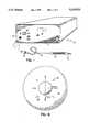
- FIG. 1is a perspective view of a thermokeratoplastic electrode system of the present invention
- FIG. 1ais a graph showing a waveform that is provided to the probe of the system
- FIG. 1bis a graph showing the amount of typical vision correction regression over time
- FIG. 1cis a representation of a nominal thermal profile within the cornea produced by the electrode system of the present invention.
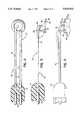
- FIG. 2is a top view of an electrode probe of the system
- FIG. 3is a side view of the probe in FIG. 2;
- FIG. 4is an enlarged view of the probe tip
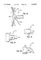
- FIG. 5is a side view showing the probe being used to treat an area of the corneal membrane
- FIG. 6is a top view showing a pattern of denatured areas of the cornea
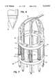
- FIG. 7is a perspective view of an alternate embodiment of the probe.
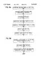
- FIGS. 8a-bshow a method for performing a procedure of the present invention
- FIG. 9shows a pattern of incisions and denatured areas to correct for a myopic condition
- FIG. 10shows another pattern of incisions and denatured areas to correct for hyperopic conditions
- FIG. 11shows a preferred embodiment of the present invention
- FIG. 11ais an enlarged view of the tip of FIG. 11;
- FIG. 12is a perspective view of a probe with the return electrode as a lid speculum that maintains the eye lid in an open position;
- FIG. 13is a side view of an alternate probe tip embodiment
- FIG. 14is a side view of an alternate probe tip embodiment
- FIG. 15is a side view of an alternate probe tip embodiment
- FIG. 16is a side view of an alternate probe tip embodiment
- FIG. 17is a side view of an alternate probe tip embodiment
- FIG. 18is a side view of an alternate probe embodiment
- FIG. 19is a schematic of a circuit which limits the use of a probe beyond a predetermined useful life
- FIG. 20is a side view of an alternate probe tip design
- FIG. 21is an enlarged cross-sectional view of the probe tip
- FIG. 22is an enlarged view of the probe tip inserted into a cornea.
- FIG. 1shows a thermokeratoplastic electrode system 10 of the present invention.
- the system 10includes an electrode probe 12 coupled to a power supply unit 14.
- the power supply unit 14contains a power supply which can deliver power to the probe 12.
- the probe 12has a hand piece 16 and wires 18 that couple the probe electrodes to a connector 20 that plugs into a mating receptacle 22 located on the front panel 24 of the power unit.
- the hand piece 16may be constructed from a non-conductive material and is approximately 0.5 inches in diameter and 5 inches long.
- the power supply 14provides a predetermined amount of energy, through a controlled application of power for a predetermined time duration.
- the power supply 14may have manual controls that allow the user to select treatment parameters such as the power and time duration.
- the power supply 14can also be constructed to provide an automated operation.
- the supply 14may have monitors and feedback systems for measuring tissue impedance, tissue temperature and other parameters, and adjust the output power of the supply to accomplish the desired results.
- the unitmay also have a display that indicates the number of remaining uses available for the probe 12.
- the power supplyprovides a constant current source and voltage limiting to prevent arcing.
- the power unit 14may have an upper voltage limit and/or upper power limit which terminates power to the probe when the output voltage or power of the unit exceeds a predetermined value.
- the power unit 14may also contain monitor and alarm circuits which monitor the resistance or impedance of the load and provide an alarm when the resistance/impedance value exceeds and/or falls below predefined limits. The alarm may provide either an audio and/or visual indication to the user that the resistance/impedance value has exceeded the outer predefined limits.
- the unitmay contain a ground fault indicator, and/or a tissue temperature monitor.
- the front panel of the power unittypically contains meters and displays that provide an indication of the power, frequency, etc., of the power delivered to the probe.
- the power unit 14may deliver a power output in a frequency range of 5 KHz-50 MHz. In the preferred embodiment, power is provided to the probe at a frequency in the range of 500 KHz. The unit 14 is designed so that the power supplied to the probe 12 does not exceed 1.2 watts (W). The time duration of each application of power to a particular corneal location is typically between 0.1-1.0 seconds. The unit 14 is preferably set to deliver approximately 0.75 W of power for 0.75 seconds.
- FIG. 1ashows a typical voltage waveform that is applied by the unit 14. Each pulse of energy delivered by the unit 14 is a highly damped signal, typically having a crest factor (peak voltage/RMS voltage) greater than 10:1. Each power dissipation is provided at a repetitive rate. The repetitive rate may range between 4-12 KHz and is preferably set at 8 KHz.
- the systemhas a switch which controls the application of power to the probe 12.
- the power unit 14also contains a timer circuit which allows power to be supplied to the probe 12 for a precise predetermined time interval.
- the timermay be a Dose timer or other similar conventional circuitry which terminates power to the probe after a predetermined time interval.
- the unitmay also allow the user to apply power until the switch is released.
- the power supplymay be a unit sold by Birtcher Medical Co. under the trademark HYFRECATOR PLUS, Model 7-797 which is modified to have voltage, waveform, time durations and power limits to comply with the above cited specifications.
- the power unit 14may have a control member 26 to allow the user to select between a "uni-polar" or a "bi-polar” operation.
- the power supply 14may be constructed to provide a single range of numerical settings, whereupon the appropriate output power, time duration and repetition rate are determined by the hardware and software of the unit.
- the front panel of the power unitmay also have control members (not shown) that allow the surgeon to vary the power, frequency, timer interval, etc. of the unit.
- the return electrode (not shown) for a uni-polar probemay be coupled to the power unit through a connector located on the unit.
- the return electrodeis preferably a cylindrical bar that is held by the patient, or an eye fixation electrode.
- FIG. 1bshows the amount of regression in the vision correction of the eye.
- the eyeswere initially overcorrected to compensate for the known regression in the procedure. As shown in FIG. 1b, the regression became stabilized after approximately 60 days and completely stabilized after 180 days. The error in overcorrection was within +/-0.5 diopters.
- FIG. 1cshows nominal thermal profiles produced by the application of power to the cornea.
- the corneaincludes an epithelium layer, a Bowmans membrane, a stroma, a Descemets membrane and a endothelium layer.
- the applicantprovides the following discussion on the possible effects of the present method on the cornea of the eye.
- the cycle of dehydration and outward current flowcontinues until the resistance from the tip to the outer rim of the corneal surface, and the full thermal profile, is significantly high to prevent further current flow of a magnitude to further cause denaturing of the corneal tissue.
- the direct contact of the probe with the cornea along the specific power/time settings of the power sourcecreates a thermal profile that denatures both the Bowman's membrane and the stroma.
- the denaturing of both the Bowman's membrane and the stroma in a circular patterncreates a linked belt type contracted annular ring. This annular ring will create a steepening of the cornea and sharpen the focus of the images on the retina.
- the surface of the eyeis kept dry by applying either a dry swab to the cornea or blowing dry air or nitrogen across the surface of the eye.
- the design of the power source and the high electrical resistance of the denatured areaprovides a self limit on the amount of penetration and area of denaturing of the cornea.
- the corneaOnce denatured, the cornea provides a high impedance to any subsequent application of power so that a relatively low amount of current flows through the denatured area. It has been found that the present procedure has a self limited denatured profile of approximately no greater than 75% of the depth of the stroma. This prevents the surgeon from denaturing the eye down to the decemets membrane and endothelium layer of the cornea.
- FIG. 1cshows nominal thermal profiles for diopter corrections of -1.5 d, -2.5-3.5 d and -4.0-6.0 d, respectively.
- a -1.5 diopter correctioncreates a denatured diameter of approximately 1 mm and a stroma penetration of approximately 30%.
- a -2.5-3.5 d correctioncreates a denatured diameter of approximately 1.13 mm and a stroma penetration of approximately 50%.
- a -4.0-6.0 d correctioncreates a denature diameter of approximately 1.25 mm and a stroma penetration of approximately 75%.
- FIGS. 2-5show an embodiment of the probe 12.
- the probe 12has a first electrode 30 and a second electrode 32. Although two electrodes are described and shown, it is to be understood that the probe may have either both electrodes (bipolar) or just the first electrode (unipolar). If a unipolar probe is used, a return electrode (indifferent electrode) is typically attached to, or held by, the patient to provide a "return" path for the current of the electrode.
- Both electrodes 30 and 32extend from the hand piece 16 which contains a pair of internal insulated conductors 34 that are contact with the proximal end of the electrodes.
- the first electrode 30has a tip 36 which extends from a first spring member 38 that is cantilevered from the hand piece 16.
- the electrode 30is preferably constructed from a phosphor-bronze or stainless steel, wire or tube, that is 0.2-1.5 mm in diameter.
- the spring portion 38 of the first electrode 30is preferably 50 millimeters (mm) long.
- the tip 36has an included angle of between 15°-60°, 30° nominal, and a nose radius of approximately 50 microns.
- a majority of the electrode 30is covered with an insulating material to prevent arcing, and to protect non-target tissue, the user and the patient.
- the relatively light spring force of the probeprovides a sufficient electrode pressure without penetrating the cornea.
- the second electrode 32includes a disk portion 40 which extends from a second spring member 42 that is also cantilevered from the hand piece 16.
- the disk portion 40is spaced a predetermined distance from first electrode 30 and has an aperture 44 that is concentric with the tip 36.
- the disk portion 40has an outer diameter of 5.5 mm and an aperture diameter of 3.0 mm.
- the disk 40further has a concave bottom surface 46 that generally conforms to the shape of the cornea or sclera.
- the bottom surface 46has a spherical radius of approximately 12.75 mm and a griping surface to assist in the fixation of the eye.
- the second electrode 32provides a return path for the current from the first electrode 30.
- the surface area of the disk 40is typically 20-500 times larger than the contact area of the tip 36.
- the second spring member 42is constructed to have a spring constant that is less than one-half the stiffness of the first spring member 38, so that the second electrode 32 will have a greater deflection per unit force than the first electrode 30.
- the tip 36 and disk 40are typically located at angles a' and a'' which may range between 30°-180°, with the preferred embodiment being 45°.
- the probe 12is pressed against the cornea to allow the second electrode 32 to deflect relative to the first electrode 30.
- the second electrode 32is deflected until the tip 36 is in contact with the cornea.
- the probecould be constructed as two pieces, one piece being the first electrode, and the other piece being the second electrode which also stabilizes the eye against corneal movement.
- the probehas been described and shown denaturing a cornea, it is to be understood that the probes and methods of the present invention can be used to denature other tissues to correct for wrinkles, incontinence, etc.
- the probecould be used to shrink a sphincter to correct for incontinence.
- the techniquewould be basically the same with small closely spaced dots forming a tightening line, belt or cylinder.
- FIG. 6shows a pattern of denatured areas 50 that have been found to correct hyperopic conditions.
- a circle of 8 or 16 denatured areas 50are created about the center of the cornea, outside the visual axis portion 52 of the eye.
- the visual axishas a nominal diameter of approximately 5 millimeters. It has been found that 16 denatured areas provide the most corneal shrinkage and less post-op astigmatism effects from the procedure.
- the circle of denatured areastypically have a diameter between 6-8 mm, with a preferred diameter of approximately 7 mm. If the first circle does not correct the eye deficiency, the same pattern may be repeated, or another pattern of 8 denatured areas may be created within a circle having a diameter of approximately 6.0-6.5 mm either in line or overlapping.
- overcorrected hyperopic conditionsmay be reversed up to 80% by applying asteroid, such as cortisone, to the denatured areas within 4 days of post-op and continued for 2 weeks after the procedure.
- asteroidsuch as cortisone
- the procedure of the present inventioncan then be repeated after a 30 day waiting period.
- the exact diameter of the patternmay vary from patient to patient, it being understood that the denatured spots should preferably be formed in the non-visionary portion 52 of the eye. Although a circular pattern is shown, it is to be understood that the denatured areas may be located in any location and in any pattern.
- the present inventionmay be used to correct astigmatic conditions. For correcting astigmatic conditions, the denatured areas are typically created at the end of the astigmatic flat axis. The present invention may also be used to correct radial keratotomy procedures that have overcorrected for a myopic condition.
- the probe and power settingshave been found to create denatured areas that do not reach the Decemets membrane. It has been found that denatured areas of the Bowmans layer in the field of vision may disturb the patients field of vision, particularly at night.
- the present inventionleaves a scar that is almost imperceptible by slit lamp examination 6 months after the procedure. It has been found that the denatured areas generated by the present invention do not produce the star effect caused by the refraction of light through the slits created in a corrective procedure such as radial keratotomy.
- FIG. 7shows an alternate embodiment of a probe 60 which has a plurality of first electrodes 62 coupled to a cage 64.
- the cage 64includes a first ring 66 separated from a second ring 68 by a number of spacers 70.
- the cage 64can be connected to a handle (not shown) which allows the surgeon to more easily utilize the probe 60.
- the first electrodes 62extend through apertures 72 in the rings 66 and 68.
- the electrodes 62can move relative to the cage 64 in the directions indicated by the arrows.
- the probe 60has a plurality springs 74 located between the rings and seated on washers 76 mounted to the electrodes 62.
- the springs 74bias the electrodes 62 into the positions shown in FIG. 7.
- the probe 60includes 8 electrodes arranged in a circular pattern having a 7.0 millimeter diameter.
- the probe 60is pressed onto the cornea so that the electrodes 62 move relative to the cage 64.
- the spring constant of the springs 74is relatively low so that there is a minimal counterforce on the tissue.
- a currentis supplied to the electrodes 62 through wires 78 attached thereto.
- the probe 60is preferably used as a uni-polar device, wherein the current flows through the tissue and into a return electrode attached to or held by the patient.
- FIGS. 8a and 8bshow a preferred method of correcting for hyperopic conditions using the electrode system of the present invention.
- refractive readingsare initially taken of both eyes with, and then without, cycloplasia.
- procedure block 102the interoccular pressure and cornea thickness at the center of the eye are taken with a tonometer and pacymeter, respectively. If the interoccular pressure is 20 mm Hg or greater, for I.O.P. reduction, 1 drop of a 0.5% solution marketed under the trademark "Betagan" is applied to the cornea twice a day for 2-3 months and then initial test are repeated. A topography reading of the eye is then taken to determine the shape of the cornea in procedural block 104.
- the patientis given a mild tranquilizer such as 5 mg of valium, and the surgeon administers drops, such as the drops marketed under the trademark "Madryacil", to dilate the pupil and freeze accommodation, in block 106.
- dropssuch as the drops marketed under the trademark "Madryacil”
- 2 drops of a topical cocaine commonly known as "Proparacaine”is administered to the eyes in block 108.
- an in line microscope lightis directed to the cornea for marking purposes. Then the lighting may be directed in a lateral direction across the cornea. Laterally lighting the eye has been found to provide good visualization without irritating or photobleaching the retina.
- the surgeonmarks 8 or 16 spots on the cornea, wherein the pattern has a preferred diameter of approximately 7 mm.
- the surgeonsets the power and duration setting of the power unit to the proper setting.
- the surgeonplaces the tip at one of the spot markings and depresses the foot switch of the system, so that power is supplied to the probe and transferred into the cornea. This process is repeated at all of the spot markings.
- the epithelium of the denatured areasare then removed with a spatula in block 116. If a diopter correction of -2.5-3.5 d, or -4.0-6.0 d is required the tip is again placed in contact with the spots and power is applied to the cornea to generate a deeper thermal profile in the stroma. The procedure is then checked with an autorefractor.
- the eyesare covered with a patch or dark glasses, and the patient is given medication, in block 118.
- the patientpreferably takes an antibiotic such as a drug marketed under the trademark "Tobrex" every 2 hours for 48 hours, and then 3 times a day for 5 days.
- the patientalso preferably takes an oral analgesic, such as a drug marketed under the trademark "Dolac”, 10 mg every 8 hours for 48 hours and a drug marketed under the trademark "Globaset” every 8 hours for 48 hours. If the patient has been overcorrected, the procedure can be reversed by waiting 3-4 days after the procedure and then administering to the eyes 1 drop of asteroid such as cortisone, 3 times a day for 1-2 weeks.
- FIG. 9shows a pattern of denatured areas 130 combined with a pattern of incisions 132 that can correct myopic conditions.
- the incisionscan be made with a knife or laser in accordance with conventional radial keratotomy procedures.
- the incisionsare made from a 3.5 mm diameter to within 1 mm of the limbus at a depth of approximately 85% of the cornea.
- Denatured areasare then created between the incisions 132 using the procedure described above.
- the power unitis preferably set at 0.75 W of power and a time duration of 0.75 seconds.
- the slow heating of the corneais important for minimizing regression, and as such 0.75 seconds has been found to be a preferable time duration to account for the patients fixation ability and the surgeons reaction time.
- the denatured areaspull the incisions to assist in the reshaping of the cornea. This procedure has been found to be effective for diopter corrections up to +10.0 d. Penetrating the cornea only 85% instead of conventional keratotomy incisions of 95% reduces the risk of puncturing the decemets membrane and the endothelium layer. This is to be distinguished from conventional radial keratotomy procedures which cannot typically correct for more than 3.5 diopters.
- the denatured pattern shown in FIG. 6has been shown to correct up to 7.0 diopters.
- a circumferential pattern of incisions 134may be created in addition to a pattern of denatured areas 136, to increase the correction up to 10.0 diopters.
- the incisionswill weaken the eye and allow a more pronounced reshaping of the eye.
- the pattern of incisionsmay be created at either a 6 mm diameter or a 8 mm diameter.
- the incisionstypically penetrate no greater than 75% of the cornea.
- the contractive forces of the denatured areasmay create gaps in the incisions. It may be preferable to fill the gaps with collagen or other suitable material.
- FIG. 11shows an alternate embodiment of a probe which has a single electrode 140.
- the electrode 140has a tip 142 which is preferably 0.009 inches in diameter.
- the tipextends from a spring beam 144 that is bent so that the surgeon can place the tip onto the cornea over nose and brow without impairing the surgeon's vision.
- the spring beam 144is preferably insulated and is 0.2-1.5 mm in diameter.
- the spring beam 144extends from a base 146 that is inserted into the hand piece.
- the base 146is preferably constructed from stainless steel and is 0.030-0.125 inches in diameter, with a preferred diameter of 0.060-0.095 inches.
- the end of the tip 142is preferably flat and has a textured surface 148.
- the textured surface 148slightly grips the cornea so that the tip does not move away from the marking when power is applied to the eye.
- the probe 200has a return electrode lid speculum 202 that maintains the eye lid in an open position.
- the speculum 202has a pair of cups 204 located at the end of wire 206.
- the cups 204are placed under an eye lid and maintain the position of the lid during the procedure.
- Extending from the lid speculum 202is a wire 208 that is typically plugged into the unit 14 "return" connector. It has been found that the procedure of the present invention will produce more consistent results when the probe 200 uses the lid speculum 202 as the return electrode.
- the impedance path between the probe 200 and the lid speculum 202is relatively consistent because of the relatively short distance between the lid speculum 202 and the probe 200, and the wet interface between the cornea and the lid speculum 202.
- FIGS. 13-15show alternate probe tip embodiments.
- the tipshave steps that increase the current density at the corneal interface.
- the tipsare preferably constructed from a stainless steel that is formed to the shapes shown.
- the tip 220 shown in FIG. 13has a cylindrical step 222 that extends from a base 224.
- the step 222terminates to a point, although it is to be understood that the end of the step 222 may have a flat surface.
- the base 224has a diameter of 350 microns (um), and the step 222 has a diameter of 190 microns and a length of 210 microns.
- the tip 230 shown in FIG. 14,has a first step 232 extending from a base portion 234 and a second step 236 extending from the first step 232.
- the end of the second step 236may be textured to improve the contact between the probe and the cornea.
- the first step 232has a diameter of 263 microns and a length of 425 microns
- the second step 236has a diameter of 160 microns and a length of 150 microns.
- the tip 240 shown in FIG. 15,has a first step 242 that extends from a base portion 244 and a second tapered step 246 that extends from the first step 242.
- the first step 242has a diameter of 290 microns and a length of 950 microns.
- the second step 246has a diameter of 150 microns, a length of 94 microns and a radius of 70 microns.
- FIGS. 16 and 17show alternate probe tip embodiments which have an outer electrode concentric with an inner electrode.
- the electrodesare coupled to the unit so that the electrodes can provide current to the cornea either simultaneously or sequentially.
- the inner electrodewill apply power with a greater current density that the outer electrode.
- the dual electrode probesallow the surgeon to create different thermal profiles, by varying the current densities, waveforms, etc. of the electrodes.
- the probe 250 shown in FIG. 16has an inner electrode 252 that is concentric with an intermediate layer of insulative material 254 and an outer conductive layer 256.
- the inner electrode 252may have a diameter of 125 microns and extend from the outer layers a length of 150 microns.
- the outer layer 256may have diameter of 350 microns.
- the inner electrode 252may be capable of being retracted into the insulative layer 254 so that the inner electrode 252 is flush with the outer electrode 256, or may be adjusted between flush and full extension, either manually or under servo control.
- FIG. 17shows another alternate embodiment, wherein the probe 260 has an additional outer sleeve 262.
- the sleeve 262has an internal passage 264 that supplies a fluid.
- the fluidmay be a gas that stabilizes the current path to the cornea or a relatively high impedance solution (such as distilled water) which provides a coolant for the eye.
- FIG. 18shows an economical detachable probe 270 embodiment.
- the probe tip 270has a conductive wire 272 that is located within a plastic outer housing 274.
- the probe tip 270has a flexible section 276 that extends from a body 278, preferably at a 45° angle.
- the tip 280extends from the flexible section 276, preferably at a 90° angle.
- Extending from the opposite end of the handle 278is a male connector 282.
- the connector 282may have a conductive sleeve 284 that is inserted into the socket 286 of a female probe connector 288.
- the end of the wire 272may be pressed between the inner surface of the sleeve 284 and the outer surface of the male connector 282 to provide an electrical interconnect between the tip end 280 and the female probe connector 288.
- the sleeve 284may have a detent 290 to secure the probe tip 270 to the probe connector 288.
- the probe tip end 280may have distal shape configurations similar to the tips shown in FIGS. 11, 13, 14, 15, 16, or 17.
- FIG. 19shows a circuit 300 that will prevent the use of the probe tip beyond a predetermined useful life.
- the circuit 300has a plurality of fuses 302 that are blown each time the probe is used for a procedure. The probe is rendered inoperative when all of the fuses 302 are blown.
- the circuit 200typically has 10-30 fuses 302, so that the probe can only be used 10-30 times.
- the circuit 300(not shown) is preferably located on a printed circuit board (not shown) mounted to the probe.
- the fuses 302may be covered with a flash inhibitor such as silica sand to prevent fuse alloy splatter/spray when the fuses are blown.
- the fuses 302are connected to drivers 304 that are coupled to a plurality of serial to parallel shift registers 306.
- the clock pin (CLK) pins and input pin D of the first shift registerare connected to the unit 14.
- the unit 14initially provides an input to the first shift register and then shifts the input through the registers 306 by providing a series of pulses on the clock pin CLK.
- An active output of a register 306will enable the corresponding driver 304 and select the corresponding fuse 302.
- the unit 14may clock the input through the shift registers 306 in accordance with an algorithm contained in hardware or software of the unit, wherein each clock signal corresponds to the end of a procedure.
- a clock signalmay be generated, and a fuse blown, upon the occurrence of four shots that have a power greater than 0.16 W and a duration greater than 0.25 seconds.
- the circuit 300may have a separate sample unit 308 that is coupled to the unit 14 and the fuses 302.
- the sample unit 308may have an optical coupler 310 which isolates the unit 14 from power surges, etc. or may be any voltage or current threshold/comparator circuitry known in the art.
- the sample unit 308may have a relay 312 that closes a switch when the fuses 302 are to be sampled.
- the sample circuit 308samples the fuses 302 to determine how many fuses 302 are not blown.
- the number of remaining fuses 302, which correlate to the amount of procedures that can be performed with that particular probe,may be provided by a display on the unit 14. By way of example, after sampling the fuses, the unit 14 may display the number 6 providing an indication that 6 more procedures can be performed with the probe. A 0 on the display may provide an indication that the probe must be replaced.
- the unit 14sets relay 312 to "sample” and clocks an input through the registers 306. If the fuse 302 is not blown when the corresponding driver 304 is enabled by the output of the register, the optical coupler 310 will be enabled. If the fuse 302 is blown the optical coupler 310 will not be enabled. The process of enabling a driver 304 and monitoring the output of optical coupler 310 is repeated for each fuse 302. The unit 14 counts the number of viable fuse links remaining to determine the remaining useful lives of the probe.
- FIG. 20shows an alternate probe tip design 350.
- the probe tip 350includes a spring beam 352 that extends from a handle 354. Also extending from the handle 354 is a male connector 356.
- the male connector 356can be connected to the female connector of the probe shown in FIG. 18.
- the connector 356allows the tip 350 to be replaced with a new unit.
- the handle 354preferably has an outer plastic shell 358 that can be grasped by the surgeon.
- the shell 358is constructed from a dielectric material that insulates the surgeon from the current flowing through the probe.
- the spring beam 352is also typically covered with an electrically insulating material. Attached to the spring beam 352 is a tip support member 360.
- the tip support 360has a tip 362 which extends from a stop 364.
- the tip 362may be the point of a wire 366 that extends to the spring beam 352.
- the wire 366may be strengthened by a thickened base portion 368.
- the thicker wire portion 368can be either a stepped single wire or a wire inserted into a hollow tube. There may be multiple tip supports and tips 362 attached to a single spring beam 352.
- the tip 362is inserted into the cornea.
- the length of the tip 362is typically 300-600 microns, preferably 400 microns, so that the electrode enters the stroma.
- the stop 364limits the penetration of the tip 362.
- the diameter of the tip 362is preferably 125 microns. The tip diameter is small to minimize the invasion of the eye.
- the power supplyprovides a current to the cornea through the tip 362.
- the currentdenatures the stroma to correct the shape of the cornea. Because the tip 362 is inserted into the stroma it has been found that a power no greater than 0.2 watts for a time duration no greater than 1.0 seconds will adequately denature the corneal tissue to provide optical correction of the eye.
- the frequency of the poweris typically between 1-20 KHz and preferably 4 KHz. Inserting the tip 362 into the cornea provides improved repeatability over probes placed into contact with the surface of the cornea, by reducing the variances in the electrical characteristics of the epithelium and the outer surface of the cornea.
- the spring beam 352is 0.90 inches long with a diameter of 0.05 inches.
- the tip supportmay be 0.25 inches long.
- the tip 362may have an embedded layer of dielectric material 370 that prevents current from flowing through the epithelium.
- the tip 362may be constructed from a 302 stainless steel wire that is subjected to a centerless grinding process. The grounded wire can then be exposed to a chemical milling process to create a sharp point.
Landscapes
- Health & Medical Sciences (AREA)
- Engineering & Computer Science (AREA)
- Ophthalmology & Optometry (AREA)
- Life Sciences & Earth Sciences (AREA)
- Biomedical Technology (AREA)
- Surgery (AREA)
- General Health & Medical Sciences (AREA)
- Nuclear Medicine, Radiotherapy & Molecular Imaging (AREA)
- Animal Behavior & Ethology (AREA)
- Public Health (AREA)
- Veterinary Medicine (AREA)
- Heart & Thoracic Surgery (AREA)
- Vascular Medicine (AREA)
- Physics & Mathematics (AREA)
- Optics & Photonics (AREA)
- Medical Informatics (AREA)
- Otolaryngology (AREA)
- Plasma & Fusion (AREA)
- Molecular Biology (AREA)
- Pathology (AREA)
- Radiology & Medical Imaging (AREA)
- Laser Surgery Devices (AREA)
- Surgical Instruments (AREA)
- Eye Examination Apparatus (AREA)
- Prostheses (AREA)
- Thermotherapy And Cooling Therapy Devices (AREA)
- Electrotherapy Devices (AREA)
Abstract
Description
TABLE I ______________________________________ -d DOTS/LOC LOC PWR (W) TIME (SEC) ______________________________________ 1.5 1 8 0.66 .75 2.5 2 8 0.66 .75 3.5 2 8 0.83 .75 4.5 2 16 0.66 .75 6.0 2 16 0.83 .75 ______________________________________
Claims (5)
Priority Applications (12)
| Application Number | Priority Date | Filing Date | Title |
|---|---|---|---|
| US08/488,829US5634921A (en) | 1993-08-23 | 1995-06-08 | Method and apparatus for modifications of visual acuity by thermal means |
| RU98100238/14ARU2194470C2 (en) | 1995-06-08 | 1996-02-08 | Device for performing vision acuity correction by means of heating means |
| BR9608919-9ABR9608919A (en) | 1995-06-08 | 1996-02-08 | Method and apparatus for modifying visual acuity by means of a thermal device |
| CNB961959177ACN1144604C (en) | 1995-06-08 | 1996-02-08 | Method and apparatus for modifications of visual acuity by thermal means |
| EP96905371AEP0836516A4 (en) | 1995-06-08 | 1996-02-08 | Method and apparatus for modifications of visual acuity by thermal means |
| AU49151/96AAU714774C (en) | 1995-06-08 | 1996-02-08 | Method and apparatus for modifications of visual acuity by thermal means |
| PCT/US1996/001539WO1996041656A1 (en) | 1995-06-08 | 1996-02-08 | Method and apparatus for modifications of visual acuity by thermal means |
| CA002248279ACA2248279C (en) | 1995-06-08 | 1996-02-08 | Method and apparatus for modifications of visual acuity by thermal means |
| JP50302997AJP3300855B2 (en) | 1995-06-08 | 1996-02-08 | Eye treatment probe |
| KR1019970709163AKR100314455B1 (en) | 1995-06-08 | 1996-02-08 | Method and apparatus for adjusting visual acuity by thermal means |
| IL11807496AIL118074A0 (en) | 1995-06-08 | 1996-04-29 | Method and apparatus for modifications of visual acuity by thermal means |
| ARP960103067AAR002414A1 (en) | 1995-06-08 | 1996-07-06 | PLASTIC THERMOQUERATE PROBE AND DISPOSITION INCORPORATED BY IT TO MAKE MODIFICATIONS TO VISUAL ACUTE THROUGH THERMAL MEANS. |
Applications Claiming Priority (4)
| Application Number | Priority Date | Filing Date | Title |
|---|---|---|---|
| US11129693A | 1993-08-23 | 1993-08-23 | |
| US17122593A | 1993-12-20 | 1993-12-20 | |
| US08/287,657US5749871A (en) | 1993-08-23 | 1994-08-09 | Method and apparatus for modifications of visual acuity by thermal means |
| US08/488,829US5634921A (en) | 1993-08-23 | 1995-06-08 | Method and apparatus for modifications of visual acuity by thermal means |
Publications (1)
| Publication Number | Publication Date |
|---|---|
| US5634921Atrue US5634921A (en) | 1997-06-03 |
Family
ID=23941292
Family Applications (1)
| Application Number | Title | Priority Date | Filing Date |
|---|---|---|---|
| US08/488,829Expired - LifetimeUS5634921A (en) | 1993-08-23 | 1995-06-08 | Method and apparatus for modifications of visual acuity by thermal means |
Country Status (11)
| Country | Link |
|---|---|
| US (1) | US5634921A (en) |
| EP (1) | EP0836516A4 (en) |
| JP (1) | JP3300855B2 (en) |
| KR (1) | KR100314455B1 (en) |
| CN (1) | CN1144604C (en) |
| AR (1) | AR002414A1 (en) |
| BR (1) | BR9608919A (en) |
| CA (1) | CA2248279C (en) |
| IL (1) | IL118074A0 (en) |
| RU (1) | RU2194470C2 (en) |
| WO (1) | WO1996041656A1 (en) |
Cited By (72)
| Publication number | Priority date | Publication date | Assignee | Title |
|---|---|---|---|---|
| US20020002369A1 (en)* | 1993-08-23 | 2002-01-03 | Hood Larry L. | Method and apparatus for modifying visual acuity by moving a focal point of energy within a cornea |
| US20030004500A1 (en)* | 1999-04-07 | 2003-01-02 | Visx, Inc. | Interface for laser eye surgery |
| US20030181903A1 (en)* | 1993-08-23 | 2003-09-25 | Hood Larry L. | Method and apparatus for modifications of visual acuity by thermal means |
| US20030220653A1 (en)* | 2000-07-18 | 2003-11-27 | Edward Perez | Methods for producing epithelial flaps on the cornea and for placement of ocular devices and lenses beneath an epithelial flap or membrane, epithelial delaminating devices, and structures of epithelium and ocular devices and lenses |
| US6673069B1 (en) | 2000-03-30 | 2004-01-06 | Refractec, Inc. | Thermokeratoplasty system with a power supply that can determine a wet or dry cornea |
| US6702812B2 (en)* | 1996-09-20 | 2004-03-09 | Ioan Cosmescu | Multifunctional telescopic monopolar/bipolar surgical device and method therefor |
| US6723093B2 (en) | 2002-03-22 | 2004-04-20 | Refractec Inc. | Electrode assembly for a thermokeratoplasty system used to correct vision acuity |
| US20040230187A1 (en)* | 2000-06-07 | 2004-11-18 | Lee Fred T. | Multipolar electrode system for volumetric radiofrequency ablation |
| US20040230190A1 (en)* | 1998-08-11 | 2004-11-18 | Arthrocare Corporation | Electrosurgical apparatus and methods for tissue treatment and removal |
| US20060064083A1 (en)* | 2004-09-17 | 2006-03-23 | Steve Khalaj | Multi-tip probe used for an ocular procedure |
| US20060167422A1 (en)* | 2003-12-30 | 2006-07-27 | Mohsen Shahinpoor | Heat Shrink Scleral Band With Custom-Made Buckle For Retinal Detachment Surgery |
| US20070038211A1 (en)* | 2005-08-15 | 2007-02-15 | Yaldo Mazin K | Method and system for conductive keratoplasty |
| US20070038234A1 (en)* | 2005-08-15 | 2007-02-15 | Yaldo Mazin K | Instrumentation for conductive keratoplasty |
| US20070043348A1 (en)* | 2003-05-26 | 2007-02-22 | Bert Sutter | Instrument for the unipolar ablation of heart tissue |
| US20070149966A1 (en)* | 1995-11-22 | 2007-06-28 | Arthrocare Corporation | Electrosurgical Apparatus and Methods for Treatment and Removal of Tissue |
| US20070260295A1 (en)* | 2006-05-03 | 2007-11-08 | Light Sciences Corporation | Light transmission system for photoreactive therapy |
| US20070282323A1 (en)* | 2006-05-30 | 2007-12-06 | Arthrocare Corporation | Hard tissue ablation system |
| US20080033519A1 (en)* | 2003-03-14 | 2008-02-07 | Light Sciences Oncology, Inc. | Light generating device for intravascular use |
| US20090024117A1 (en)* | 2007-07-19 | 2009-01-22 | Avedro, Inc. | Eye therapy system |
| US20090149842A1 (en)* | 2007-12-05 | 2009-06-11 | David Muller | Eye therapy system |
| US20090187173A1 (en)* | 2008-01-23 | 2009-07-23 | David Muller | System and method for reshaping an eye feature |
| US7572251B1 (en) | 1995-06-07 | 2009-08-11 | Arthrocare Corporation | Systems and methods for electrosurgical tissue treatment |
| US20090209954A1 (en)* | 2008-01-23 | 2009-08-20 | David Muller | System and method for reshaping an eye feature |
| US7632267B2 (en)* | 2005-07-06 | 2009-12-15 | Arthrocare Corporation | Fuse-electrode electrosurgical apparatus |
| US7678069B1 (en) | 1995-11-22 | 2010-03-16 | Arthrocare Corporation | System for electrosurgical tissue treatment in the presence of electrically conductive fluid |
| US7691101B2 (en) | 2006-01-06 | 2010-04-06 | Arthrocare Corporation | Electrosurgical method and system for treating foot ulcer |
| US20100094197A1 (en)* | 2008-09-30 | 2010-04-15 | John Marshall | Eye therapy system |
| US20100185192A1 (en)* | 2008-11-11 | 2010-07-22 | Avedro, Inc. | Eye therapy system |
| US20100256626A1 (en)* | 2009-04-02 | 2010-10-07 | Avedro, Inc. | Eye therapy system |
| US20100256705A1 (en)* | 2009-04-02 | 2010-10-07 | Avedro, Inc. | Eye therapy system |
| US20100274330A1 (en)* | 2003-03-14 | 2010-10-28 | Light Sciences Oncology, Inc. | Device for treatment of blood vessels using light |
| US20100280509A1 (en)* | 2009-04-02 | 2010-11-04 | Avedro, Inc. | Eye Therapy System |
| US7862560B2 (en) | 2007-03-23 | 2011-01-04 | Arthrocare Corporation | Ablation apparatus having reduced nerve stimulation and related methods |
| US20110008372A1 (en)* | 2009-07-08 | 2011-01-13 | Light Sciences Oncology, Inc. | Enhancement of light activated drug therapy through combination with other therapeutic agents |
| US20110118734A1 (en)* | 2009-11-16 | 2011-05-19 | Alcon Research, Ltd. | Capsularhexis device using pulsed electric fields |
| US20110118654A1 (en)* | 2009-10-21 | 2011-05-19 | Avedro, Inc. | Eye Therapy |
| US20110118716A1 (en)* | 2009-10-30 | 2011-05-19 | Avedro, Inc. | System and Method for Stabilizing Corneal Tissue After Treatment |
| US20110237999A1 (en)* | 2010-03-19 | 2011-09-29 | Avedro Inc. | Systems and methods for applying and monitoring eye therapy |
| USD658760S1 (en) | 2010-10-15 | 2012-05-01 | Arthrocare Corporation | Wound care electrosurgical wand |
| US8202272B2 (en) | 2007-07-19 | 2012-06-19 | Avedro, Inc. | Eye therapy system |
| US8226946B2 (en) | 2008-08-06 | 2012-07-24 | Light Sciences Oncology, Inc. | Enhancement of light activated therapy by immune augmentation using anti-CTLA-4 antibody |
| US8257350B2 (en) | 2009-06-17 | 2012-09-04 | Arthrocare Corporation | Method and system of an electrosurgical controller with wave-shaping |
| US8372067B2 (en) | 2009-12-09 | 2013-02-12 | Arthrocare Corporation | Electrosurgery irrigation primer systems and methods |
| US8398628B2 (en) | 2008-09-19 | 2013-03-19 | Avedro, Inc. | Eye therapy system |
| US8409189B2 (en) | 2008-01-23 | 2013-04-02 | Avedro, Inc. | System and method for reshaping an eye feature |
| US8460278B2 (en) | 2008-10-01 | 2013-06-11 | Avedro, Inc. | Eye therapy system |
| US8469952B2 (en) | 2008-01-23 | 2013-06-25 | Avedro, Inc. | System and method for positioning an eye therapy device |
| US8568405B2 (en) | 2010-10-15 | 2013-10-29 | Arthrocare Corporation | Electrosurgical wand and related method and system |
| US8574187B2 (en) | 2009-03-09 | 2013-11-05 | Arthrocare Corporation | System and method of an electrosurgical controller with output RF energy control |
| RU2508083C2 (en)* | 2012-03-28 | 2014-02-27 | Федеральное государственное бюджетное учреждение "Межотраслевой научно-технический комплекс "Микрохирургия глаза" имени академика С.Н. Федорова" Министерства здравоохранения и социального развития Российской Федерации | Extrascleral electrode for electrochemical lysis of intraocular new growths |
| US8685018B2 (en) | 2010-10-15 | 2014-04-01 | Arthrocare Corporation | Electrosurgical wand and related method and system |
| US8747399B2 (en) | 2010-04-06 | 2014-06-10 | Arthrocare Corporation | Method and system of reduction of low frequency muscle stimulation during electrosurgical procedures |
| US8870866B2 (en) | 2007-01-05 | 2014-10-28 | Arthrocare Corporation | Electrosurgical system with suction control apparatus, system and method |
| US8876746B2 (en) | 2006-01-06 | 2014-11-04 | Arthrocare Corporation | Electrosurgical system and method for treating chronic wound tissue |
| US9020580B2 (en) | 2011-06-02 | 2015-04-28 | Avedro, Inc. | Systems and methods for monitoring time based photo active agent delivery or photo active marker presence |
| US9044308B2 (en) | 2011-05-24 | 2015-06-02 | Avedro, Inc. | Systems and methods for reshaping an eye feature |
| US9131597B2 (en) | 2011-02-02 | 2015-09-08 | Arthrocare Corporation | Electrosurgical system and method for treating hard body tissue |
| US9498114B2 (en) | 2013-06-18 | 2016-11-22 | Avedro, Inc. | Systems and methods for determining biomechanical properties of the eye for applying treatment |
| US9498122B2 (en) | 2013-06-18 | 2016-11-22 | Avedro, Inc. | Systems and methods for determining biomechanical properties of the eye for applying treatment |
| US20170112568A1 (en)* | 2014-10-21 | 2017-04-27 | Wendy Epstein | Radio frequency handpiece for medical treatments |
| US9693818B2 (en) | 2013-03-07 | 2017-07-04 | Arthrocare Corporation | Methods and systems related to electrosurgical wands |
| US9707126B2 (en) | 2009-10-21 | 2017-07-18 | Avedro, Inc. | Systems and methods for corneal cross-linking with pulsed light |
| US9713489B2 (en) | 2013-03-07 | 2017-07-25 | Arthrocare Corporation | Electrosurgical methods and systems |
| US9801678B2 (en) | 2013-03-13 | 2017-10-31 | Arthrocare Corporation | Method and system of controlling conductive fluid flow during an electrosurgical procedure |
| US10028657B2 (en) | 2015-05-22 | 2018-07-24 | Avedro, Inc. | Systems and methods for monitoring cross-linking activity for corneal treatments |
| US10114205B2 (en) | 2014-11-13 | 2018-10-30 | Avedro, Inc. | Multipass virtually imaged phased array etalon |
| US10258809B2 (en) | 2015-04-24 | 2019-04-16 | Avedro, Inc. | Systems and methods for photoactivating a photosensitizer applied to an eye |
| US10307610B2 (en) | 2006-01-18 | 2019-06-04 | Light Sciences Oncology Inc. | Method and apparatus for light-activated drug therapy |
| US10350111B2 (en) | 2014-10-27 | 2019-07-16 | Avedro, Inc. | Systems and methods for cross-linking treatments of an eye |
| US20210030591A1 (en)* | 2018-03-12 | 2021-02-04 | Geuder Ag | Ophthalmological surgical set and a contact lens |
| US11207410B2 (en) | 2015-07-21 | 2021-12-28 | Avedro, Inc. | Systems and methods for treatments of an eye with a photosensitizer |
| US11251635B2 (en) | 2017-12-19 | 2022-02-15 | Welch Allyn, Inc. | Vital signs monitor with a removable and dischargable battery |
Families Citing this family (1)
| Publication number | Priority date | Publication date | Assignee | Title |
|---|---|---|---|---|
| US7628788B2 (en)* | 2005-12-30 | 2009-12-08 | Biosense Webster, Inc. | Ablation catheter with improved tip cooling |
Citations (33)
| Publication number | Priority date | Publication date | Assignee | Title |
|---|---|---|---|---|
| US3595239A (en)* | 1969-04-04 | 1971-07-27 | Roy A Petersen | Catheter with electrical cutting means |
| US3776230A (en)* | 1973-04-18 | 1973-12-04 | C Neefe | Method of rapidly reshaping the cornea to eliminate refractive errors |
| US3963030A (en)* | 1973-04-16 | 1976-06-15 | Valleylab, Inc. | Signal generating device and method for producing coagulation electrosurgical current |
| US4301802A (en)* | 1980-03-17 | 1981-11-24 | Stanley Poler | Cauterizing tool for ophthalmological surgery |
| US4326529A (en)* | 1978-05-26 | 1982-04-27 | The United States Of America As Represented By The United States Department Of Energy | Corneal-shaping electrode |
| US4347842A (en)* | 1980-02-15 | 1982-09-07 | Mark Beale | Disposable electrical surgical suction tube and instrument |
| US4381007A (en)* | 1981-04-30 | 1983-04-26 | The United States Of America As Represented By The United States Department Of Energy | Multipolar corneal-shaping electrode with flexible removable skirt |
| US4461294A (en)* | 1982-01-20 | 1984-07-24 | Baron Neville A | Apparatus and process for recurving the cornea of an eye |
| US4500832A (en)* | 1983-02-28 | 1985-02-19 | Codman & Shurtleff, Inc. | Electrical transformer |
| US4633870A (en)* | 1985-06-26 | 1987-01-06 | Sauer Jude S | Apparatus for effecting anastomosis of tubular tissue by laser welding |
| US4729372A (en)* | 1983-11-17 | 1988-03-08 | Lri L.P. | Apparatus for performing ophthalmic laser surgery |
| US4739759A (en)* | 1985-02-26 | 1988-04-26 | Concept, Inc. | Microprocessor controlled electrosurgical generator |
| US4747820A (en)* | 1986-04-09 | 1988-05-31 | Cooper Lasersonics, Inc. | Irrigation/aspiration manifold and fittings for ultrasonic surgical aspiration system |
| US4798204A (en)* | 1987-05-13 | 1989-01-17 | Lri L.P. | Method of laser-sculpture of the optically used portion of the cornea |
| US4898169A (en)* | 1987-05-08 | 1990-02-06 | Boston Scientific Corporation | Medical instrument for therapy of hemorrhoidal lesions |
| US4907585A (en)* | 1987-12-03 | 1990-03-13 | Schachar Ronald A | Method for improving farsightedness |
| US4931047A (en)* | 1987-09-30 | 1990-06-05 | Cavitron, Inc. | Method and apparatus for providing enhanced tissue fragmentation and/or hemostasis |
| WO1990012618A1 (en)* | 1989-04-21 | 1990-11-01 | Spears Kenneth G | Laser thermal keratoplasty system |
| US4976709A (en)* | 1988-12-15 | 1990-12-11 | Sand Bruce J | Method for collagen treatment |
| US4988334A (en)* | 1986-04-09 | 1991-01-29 | Valleylab, Inc. | Ultrasonic surgical system with aspiration tubulation connector |
| US5015227A (en)* | 1987-09-30 | 1991-05-14 | Valleylab Inc. | Apparatus for providing enhanced tissue fragmentation and/or hemostasis |
| US5025811A (en)* | 1990-02-16 | 1991-06-25 | Dobrogowski Michael J | Method for focal destruction of eye tissue by electroablation |
| US5035695A (en)* | 1987-11-30 | 1991-07-30 | Jaroy Weber, Jr. | Extendable electrocautery surgery apparatus and method |
| US5071418A (en)* | 1990-05-16 | 1991-12-10 | Joseph Rosenbaum | Electrocautery surgical scalpel |
| US5137530A (en)* | 1985-09-27 | 1992-08-11 | Sand Bruce J | Collagen treatment apparatus |
| US5174304A (en)* | 1990-02-16 | 1992-12-29 | Latina Mark A | Electrocycloablation apparatus and method |
| US5188125A (en)* | 1982-01-04 | 1993-02-23 | Keravision, Inc. | Method for corneal curvature adjustment |
| US5190517A (en)* | 1991-06-06 | 1993-03-02 | Valleylab Inc. | Electrosurgical and ultrasonic surgical system |
| US5195954A (en)* | 1990-06-26 | 1993-03-23 | Schnepp Pesch Wolfram | Apparatus for the removal of deposits in vessels and organs of animals |
| US5217459A (en)* | 1991-08-27 | 1993-06-08 | William Kamerling | Method and instrument for performing eye surgery |
| US5312401A (en)* | 1991-07-10 | 1994-05-17 | Electroscope, Inc. | Electrosurgical apparatus for laparoscopic and like procedures |
| US5346491A (en)* | 1991-03-28 | 1994-09-13 | Sony Corporation | Feed device for bipolar electrodes for capsulotomy |
| US5533999A (en)* | 1993-08-23 | 1996-07-09 | Refractec, Inc. | Method and apparatus for modifications of visual acuity by thermal means |
Family Cites Families (2)
| Publication number | Priority date | Publication date | Assignee | Title |
|---|---|---|---|---|
| US5437658A (en)* | 1992-10-07 | 1995-08-01 | Summit Technology, Incorporated | Method and system for laser thermokeratoplasty of the cornea |
| PL313222A1 (en)* | 1993-08-23 | 1996-06-10 | Larry L Hood | Method of modifying visual acuity using technical means |
- 1995
- 1995-06-08USUS08/488,829patent/US5634921A/ennot_activeExpired - Lifetime
- 1996
- 1996-02-08KRKR1019970709163Apatent/KR100314455B1/ennot_activeExpired - Fee Related
- 1996-02-08BRBR9608919-9Apatent/BR9608919A/ennot_activeIP Right Cessation
- 1996-02-08JPJP50302997Apatent/JP3300855B2/ennot_activeExpired - Fee Related
- 1996-02-08CACA002248279Apatent/CA2248279C/ennot_activeExpired - Fee Related
- 1996-02-08WOPCT/US1996/001539patent/WO1996041656A1/ennot_activeApplication Discontinuation
- 1996-02-08EPEP96905371Apatent/EP0836516A4/ennot_activeWithdrawn
- 1996-02-08RURU98100238/14Apatent/RU2194470C2/ennot_activeIP Right Cessation
- 1996-02-08CNCNB961959177Apatent/CN1144604C/ennot_activeExpired - Fee Related
- 1996-04-29ILIL11807496Apatent/IL118074A0/enunknown
- 1996-07-06ARARP960103067Apatent/AR002414A1/ennot_activeApplication Discontinuation
Patent Citations (33)
| Publication number | Priority date | Publication date | Assignee | Title |
|---|---|---|---|---|
| US3595239A (en)* | 1969-04-04 | 1971-07-27 | Roy A Petersen | Catheter with electrical cutting means |
| US3963030A (en)* | 1973-04-16 | 1976-06-15 | Valleylab, Inc. | Signal generating device and method for producing coagulation electrosurgical current |
| US3776230A (en)* | 1973-04-18 | 1973-12-04 | C Neefe | Method of rapidly reshaping the cornea to eliminate refractive errors |
| US4326529A (en)* | 1978-05-26 | 1982-04-27 | The United States Of America As Represented By The United States Department Of Energy | Corneal-shaping electrode |
| US4347842A (en)* | 1980-02-15 | 1982-09-07 | Mark Beale | Disposable electrical surgical suction tube and instrument |
| US4301802A (en)* | 1980-03-17 | 1981-11-24 | Stanley Poler | Cauterizing tool for ophthalmological surgery |
| US4381007A (en)* | 1981-04-30 | 1983-04-26 | The United States Of America As Represented By The United States Department Of Energy | Multipolar corneal-shaping electrode with flexible removable skirt |
| US5188125A (en)* | 1982-01-04 | 1993-02-23 | Keravision, Inc. | Method for corneal curvature adjustment |
| US4461294A (en)* | 1982-01-20 | 1984-07-24 | Baron Neville A | Apparatus and process for recurving the cornea of an eye |
| US4500832A (en)* | 1983-02-28 | 1985-02-19 | Codman & Shurtleff, Inc. | Electrical transformer |
| US4729372A (en)* | 1983-11-17 | 1988-03-08 | Lri L.P. | Apparatus for performing ophthalmic laser surgery |
| US4739759A (en)* | 1985-02-26 | 1988-04-26 | Concept, Inc. | Microprocessor controlled electrosurgical generator |
| US4633870A (en)* | 1985-06-26 | 1987-01-06 | Sauer Jude S | Apparatus for effecting anastomosis of tubular tissue by laser welding |
| US5137530A (en)* | 1985-09-27 | 1992-08-11 | Sand Bruce J | Collagen treatment apparatus |
| US4747820A (en)* | 1986-04-09 | 1988-05-31 | Cooper Lasersonics, Inc. | Irrigation/aspiration manifold and fittings for ultrasonic surgical aspiration system |
| US4988334A (en)* | 1986-04-09 | 1991-01-29 | Valleylab, Inc. | Ultrasonic surgical system with aspiration tubulation connector |
| US4898169A (en)* | 1987-05-08 | 1990-02-06 | Boston Scientific Corporation | Medical instrument for therapy of hemorrhoidal lesions |
| US4798204A (en)* | 1987-05-13 | 1989-01-17 | Lri L.P. | Method of laser-sculpture of the optically used portion of the cornea |
| US5015227A (en)* | 1987-09-30 | 1991-05-14 | Valleylab Inc. | Apparatus for providing enhanced tissue fragmentation and/or hemostasis |
| US4931047A (en)* | 1987-09-30 | 1990-06-05 | Cavitron, Inc. | Method and apparatus for providing enhanced tissue fragmentation and/or hemostasis |
| US5035695A (en)* | 1987-11-30 | 1991-07-30 | Jaroy Weber, Jr. | Extendable electrocautery surgery apparatus and method |
| US4907585A (en)* | 1987-12-03 | 1990-03-13 | Schachar Ronald A | Method for improving farsightedness |
| US4976709A (en)* | 1988-12-15 | 1990-12-11 | Sand Bruce J | Method for collagen treatment |
| WO1990012618A1 (en)* | 1989-04-21 | 1990-11-01 | Spears Kenneth G | Laser thermal keratoplasty system |
| US5025811A (en)* | 1990-02-16 | 1991-06-25 | Dobrogowski Michael J | Method for focal destruction of eye tissue by electroablation |
| US5174304A (en)* | 1990-02-16 | 1992-12-29 | Latina Mark A | Electrocycloablation apparatus and method |
| US5071418A (en)* | 1990-05-16 | 1991-12-10 | Joseph Rosenbaum | Electrocautery surgical scalpel |
| US5195954A (en)* | 1990-06-26 | 1993-03-23 | Schnepp Pesch Wolfram | Apparatus for the removal of deposits in vessels and organs of animals |
| US5346491A (en)* | 1991-03-28 | 1994-09-13 | Sony Corporation | Feed device for bipolar electrodes for capsulotomy |
| US5190517A (en)* | 1991-06-06 | 1993-03-02 | Valleylab Inc. | Electrosurgical and ultrasonic surgical system |
| US5312401A (en)* | 1991-07-10 | 1994-05-17 | Electroscope, Inc. | Electrosurgical apparatus for laparoscopic and like procedures |
| US5217459A (en)* | 1991-08-27 | 1993-06-08 | William Kamerling | Method and instrument for performing eye surgery |
| US5533999A (en)* | 1993-08-23 | 1996-07-09 | Refractec, Inc. | Method and apparatus for modifications of visual acuity by thermal means |
Non-Patent Citations (18)
| Title |
|---|
| "A Technique for the Selective Heating of Corneal Stroma", James D. Doss, M.S. and Jose L. Albillar, Contact & Intraocular Lens Medical Jrnl., vol. 6, No. 1, Jan.-Mar. 1980, pp. 13-17. |
| "Anatomy of the Eye", Physiology of the Eye, Chapter 1, pp. 3, 6-8, 21-22. |
| "Biophysics of Electrtosurgery", C. Randle Voyles, M.D. and Robert D. Tucher, Ph.D., Excerpts from American College of Surgeons Meeting, San Francisco, CA, Oct. 1993. |
| "BipoKeratoplasty: Using Cautery to Advantage", Richsard J. Fugo, M.D., Ph.D., Ocular Surgery News, Feb. 1993, pp. 101 & 113. |
| "Combined Microwave Heating and Surface Cooling of the Cornea", B. Stuart Trembly, et al., IEEE Transactions on Biomedical Engineering, vol., 38, No. 1, Jan. 1991, pp. 85-91. |
| "Cutaneous Electrosurgery", Jack E. Sebben, M.D., pp. 14-15, 19-30, 42-43, 48, 52-55, 62-63, 77-83, 100-105. |
| "Radial Thermokeratoplasty or Hyperopia", Peter McDonnel, M.D. and Al Neumann, MD, Refractuve & Corneal Surgery, vol. 5, Jan./Feb. 1989, pp. 50-54. |
| "Radiofrequency for Hyperopia Treatment", Antonio Mendez, M.D., Beverly Hills presentation, Aug. 28, 1993. |
| "Regression of Effect Following Radial Thermokeratoplasty in Humans", Sandy T, Feldman, et al., Refractive & Corneal Surgery, vol. 5, Sep./Oct. 1989, pp. 288-291. |
| A Technique for the Selective Heating of Corneal Stroma , James D. Doss, M.S. and Jose L. Albillar, Contact & Intraocular Lens Medical Jrnl., vol. 6, No. 1, Jan. Mar. 1980, pp. 13 17.* |
| Anatomy of the Eye , Physiology of the Eye, Chapter 1, pp. 3, 6 8, 21 22.* |
| Biophysics of Electrtosurgery , C. Randle Voyles, M.D. and Robert D. Tucher, Ph.D., Excerpts from American College of Surgeons Meeting, San Francisco, CA, Oct. 1993.* |
| BipoKeratoplasty: Using Cautery to Advantage , Richsard J. Fugo, M.D., Ph.D., Ocular Surgery News, Feb. 1993, pp. 101 & 113.* |
| Combined Microwave Heating and Surface Cooling of the Cornea , B. Stuart Trembly, et al., IEEE Transactions on Biomedical Engineering, vol., 38, No. 1, Jan. 1991, pp. 85 91.* |
| Cutaneous Electrosurgery , Jack E. Sebben, M.D., pp. 14 15, 19 30, 42 43, 48, 52 55, 62 63, 77 83, 100 105.* |
| Radial Thermokeratoplasty or Hyperopia , Peter McDonnel, M.D. and Al Neumann, MD, Refractuve & Corneal Surgery, vol. 5, Jan./Feb. 1989, pp. 50 54.* |
| Radiofrequency for Hyperopia Treatment , Antonio Mendez, M.D., Beverly Hills presentation, Aug. 28, 1993.* |
| Regression of Effect Following Radial Thermokeratoplasty in Humans , Sandy T, Feldman, et al., Refractive & Corneal Surgery, vol. 5, Sep./Oct. 1989, pp. 288 291.* |
Cited By (116)
| Publication number | Priority date | Publication date | Assignee | Title |
|---|---|---|---|---|
| US20030181903A1 (en)* | 1993-08-23 | 2003-09-25 | Hood Larry L. | Method and apparatus for modifications of visual acuity by thermal means |
| US20020002369A1 (en)* | 1993-08-23 | 2002-01-03 | Hood Larry L. | Method and apparatus for modifying visual acuity by moving a focal point of energy within a cornea |
| US7572251B1 (en) | 1995-06-07 | 2009-08-11 | Arthrocare Corporation | Systems and methods for electrosurgical tissue treatment |
| US7988689B2 (en) | 1995-11-22 | 2011-08-02 | Arthrocare Corporation | Electrosurgical apparatus and methods for treatment and removal of tissue |
| US7678069B1 (en) | 1995-11-22 | 2010-03-16 | Arthrocare Corporation | System for electrosurgical tissue treatment in the presence of electrically conductive fluid |
| US20070149966A1 (en)* | 1995-11-22 | 2007-06-28 | Arthrocare Corporation | Electrosurgical Apparatus and Methods for Treatment and Removal of Tissue |
| US6702812B2 (en)* | 1996-09-20 | 2004-03-09 | Ioan Cosmescu | Multifunctional telescopic monopolar/bipolar surgical device and method therefor |
| US20040230190A1 (en)* | 1998-08-11 | 2004-11-18 | Arthrocare Corporation | Electrosurgical apparatus and methods for tissue treatment and removal |
| US6558373B1 (en) | 1999-04-07 | 2003-05-06 | Visx, Incorporated | Interface for laser eye surgery |
| US20030009159A1 (en)* | 1999-04-07 | 2003-01-09 | Visx, Inc. | Interface for laser eye surgery |
| US20030004500A1 (en)* | 1999-04-07 | 2003-01-02 | Visx, Inc. | Interface for laser eye surgery |
| US7001373B2 (en) | 1999-04-07 | 2006-02-21 | Visx, Incorporated | Interface for laser eye surgery |
| US6673069B1 (en) | 2000-03-30 | 2004-01-06 | Refractec, Inc. | Thermokeratoplasty system with a power supply that can determine a wet or dry cornea |
| US8486065B2 (en)* | 2000-06-07 | 2013-07-16 | Wisconsin Alumni Research Foundation | Radio-frequency ablation system and method using multiple electrodes |
| US20040230187A1 (en)* | 2000-06-07 | 2004-11-18 | Lee Fred T. | Multipolar electrode system for volumetric radiofrequency ablation |
| US7497866B2 (en)* | 2000-07-18 | 2009-03-03 | Tissue Engineering Refraction Inc. | Methods for producing epithelial flaps on the cornea and for placement of ocular devices and lenses beneath an epithelial flap or membrane, epithelial delaminating devices, and structures of epithelium and ocular devices and lenses |
| US20030220653A1 (en)* | 2000-07-18 | 2003-11-27 | Edward Perez | Methods for producing epithelial flaps on the cornea and for placement of ocular devices and lenses beneath an epithelial flap or membrane, epithelial delaminating devices, and structures of epithelium and ocular devices and lenses |
| US20040181218A1 (en)* | 2002-03-22 | 2004-09-16 | Larry Hood | Electrode assembly for a thermokeratoplasty system used to correct vision acuity |
| US7178231B2 (en)* | 2002-03-22 | 2007-02-20 | Refractec, Inc. | Electrode assembly for a thermokeratoplasty system used to correct vision acuity |
| US6723093B2 (en) | 2002-03-22 | 2004-04-20 | Refractec Inc. | Electrode assembly for a thermokeratoplasty system used to correct vision acuity |
| US20100274330A1 (en)* | 2003-03-14 | 2010-10-28 | Light Sciences Oncology, Inc. | Device for treatment of blood vessels using light |
| US20080033519A1 (en)* | 2003-03-14 | 2008-02-07 | Light Sciences Oncology, Inc. | Light generating device for intravascular use |
| US10376711B2 (en) | 2003-03-14 | 2019-08-13 | Light Sciences Oncology Inc. | Light generating guide wire for intravascular use |
| US20070043348A1 (en)* | 2003-05-26 | 2007-02-22 | Bert Sutter | Instrument for the unipolar ablation of heart tissue |
| US7699843B2 (en)* | 2003-05-26 | 2010-04-20 | Fehling Ag | Instrument for the unipolar ablation of heart tissue |
| US20060167422A1 (en)* | 2003-12-30 | 2006-07-27 | Mohsen Shahinpoor | Heat Shrink Scleral Band With Custom-Made Buckle For Retinal Detachment Surgery |
| US20060064083A1 (en)* | 2004-09-17 | 2006-03-23 | Steve Khalaj | Multi-tip probe used for an ocular procedure |
| US7632267B2 (en)* | 2005-07-06 | 2009-12-15 | Arthrocare Corporation | Fuse-electrode electrosurgical apparatus |
| US20070038211A1 (en)* | 2005-08-15 | 2007-02-15 | Yaldo Mazin K | Method and system for conductive keratoplasty |
| US20070038234A1 (en)* | 2005-08-15 | 2007-02-15 | Yaldo Mazin K | Instrumentation for conductive keratoplasty |
| US7374562B2 (en) | 2005-08-15 | 2008-05-20 | Yaldo Mazin K | Method and system for conductive keratoplasty |
| US9168087B2 (en) | 2006-01-06 | 2015-10-27 | Arthrocare Corporation | Electrosurgical system and method for sterilizing chronic wound tissue |
| US8636685B2 (en) | 2006-01-06 | 2014-01-28 | Arthrocare Corporation | Electrosurgical method and system for treating foot ulcer |
| US7691101B2 (en) | 2006-01-06 | 2010-04-06 | Arthrocare Corporation | Electrosurgical method and system for treating foot ulcer |
| US8663154B2 (en) | 2006-01-06 | 2014-03-04 | Arthrocare Corporation | Electrosurgical method and system for treating foot ulcer |
| US8663153B2 (en) | 2006-01-06 | 2014-03-04 | Arthrocare Corporation | Electrosurgical method and system for treating foot ulcer |
| US9254167B2 (en) | 2006-01-06 | 2016-02-09 | Arthrocare Corporation | Electrosurgical system and method for sterilizing chronic wound tissue |
| US8663152B2 (en) | 2006-01-06 | 2014-03-04 | Arthrocare Corporation | Electrosurgical method and system for treating foot ulcer |
| US8876746B2 (en) | 2006-01-06 | 2014-11-04 | Arthrocare Corporation | Electrosurgical system and method for treating chronic wound tissue |
| US10307610B2 (en) | 2006-01-18 | 2019-06-04 | Light Sciences Oncology Inc. | Method and apparatus for light-activated drug therapy |
| US20070260295A1 (en)* | 2006-05-03 | 2007-11-08 | Light Sciences Corporation | Light transmission system for photoreactive therapy |
| US8235975B2 (en)* | 2006-05-03 | 2012-08-07 | Light Sciences Oncology, Inc. | Light transmission system for photoreactive therapy |
| US8057464B2 (en)* | 2006-05-03 | 2011-11-15 | Light Sciences Oncology, Inc. | Light transmission system for photoreactive therapy |
| US20120089207A1 (en)* | 2006-05-03 | 2012-04-12 | Light Sciences Oncology, Inc. | Light transmission system for photoreactive therapy |
| USRE47491E1 (en)* | 2006-05-03 | 2019-07-09 | Light Sciences Oncology, Inc. | Light transmission system for photoreactive therapy |
| US8444638B2 (en) | 2006-05-30 | 2013-05-21 | Arthrocare Corporation | Hard tissue ablation system |
| US20070282323A1 (en)* | 2006-05-30 | 2007-12-06 | Arthrocare Corporation | Hard tissue ablation system |
| US8114071B2 (en) | 2006-05-30 | 2012-02-14 | Arthrocare Corporation | Hard tissue ablation system |
| US9254164B2 (en) | 2007-01-05 | 2016-02-09 | Arthrocare Corporation | Electrosurgical system with suction control apparatus, system and method |
| US8870866B2 (en) | 2007-01-05 | 2014-10-28 | Arthrocare Corporation | Electrosurgical system with suction control apparatus, system and method |
| US7862560B2 (en) | 2007-03-23 | 2011-01-04 | Arthrocare Corporation | Ablation apparatus having reduced nerve stimulation and related methods |
| US20090024117A1 (en)* | 2007-07-19 | 2009-01-22 | Avedro, Inc. | Eye therapy system |
| US8202272B2 (en) | 2007-07-19 | 2012-06-19 | Avedro, Inc. | Eye therapy system |
| US8652131B2 (en) | 2007-07-19 | 2014-02-18 | Avedro, Inc. | Eye therapy system |
| US8992516B2 (en) | 2007-07-19 | 2015-03-31 | Avedro, Inc. | Eye therapy system |
| US20090149842A1 (en)* | 2007-12-05 | 2009-06-11 | David Muller | Eye therapy system |
| US8545487B2 (en) | 2007-12-05 | 2013-10-01 | Avedro Inc. | Eye therapy system |
| US20090209954A1 (en)* | 2008-01-23 | 2009-08-20 | David Muller | System and method for reshaping an eye feature |
| US8348935B2 (en) | 2008-01-23 | 2013-01-08 | Avedro, Inc. | System and method for reshaping an eye feature |
| US20090187173A1 (en)* | 2008-01-23 | 2009-07-23 | David Muller | System and method for reshaping an eye feature |
| US8409189B2 (en) | 2008-01-23 | 2013-04-02 | Avedro, Inc. | System and method for reshaping an eye feature |
| US8469952B2 (en) | 2008-01-23 | 2013-06-25 | Avedro, Inc. | System and method for positioning an eye therapy device |
| US8226946B2 (en) | 2008-08-06 | 2012-07-24 | Light Sciences Oncology, Inc. | Enhancement of light activated therapy by immune augmentation using anti-CTLA-4 antibody |
| US8398628B2 (en) | 2008-09-19 | 2013-03-19 | Avedro, Inc. | Eye therapy system |
| US8366689B2 (en) | 2008-09-30 | 2013-02-05 | Avedro, Inc. | Method for making structural changes in corneal fibrils |
| US20100094197A1 (en)* | 2008-09-30 | 2010-04-15 | John Marshall | Eye therapy system |
| US8460278B2 (en) | 2008-10-01 | 2013-06-11 | Avedro, Inc. | Eye therapy system |
| US20100185192A1 (en)* | 2008-11-11 | 2010-07-22 | Avedro, Inc. | Eye therapy system |
| US8882757B2 (en) | 2008-11-11 | 2014-11-11 | Avedro, Inc. | Eye therapy system |
| US8574187B2 (en) | 2009-03-09 | 2013-11-05 | Arthrocare Corporation | System and method of an electrosurgical controller with output RF energy control |
| US20100256626A1 (en)* | 2009-04-02 | 2010-10-07 | Avedro, Inc. | Eye therapy system |
| US20100256705A1 (en)* | 2009-04-02 | 2010-10-07 | Avedro, Inc. | Eye therapy system |
| US20100280509A1 (en)* | 2009-04-02 | 2010-11-04 | Avedro, Inc. | Eye Therapy System |
| US8712536B2 (en) | 2009-04-02 | 2014-04-29 | Avedro, Inc. | Eye therapy system |
| US8257350B2 (en) | 2009-06-17 | 2012-09-04 | Arthrocare Corporation | Method and system of an electrosurgical controller with wave-shaping |
| US9138282B2 (en) | 2009-06-17 | 2015-09-22 | Arthrocare Corporation | Method and system of an electrosurgical controller with wave-shaping |
| US20110008372A1 (en)* | 2009-07-08 | 2011-01-13 | Light Sciences Oncology, Inc. | Enhancement of light activated drug therapy through combination with other therapeutic agents |
| US8870934B2 (en) | 2009-10-21 | 2014-10-28 | Avedro, Inc. | Eye therapy system |
| US20110118654A1 (en)* | 2009-10-21 | 2011-05-19 | Avedro, Inc. | Eye Therapy |
| US8574277B2 (en) | 2009-10-21 | 2013-11-05 | Avedro Inc. | Eye therapy |
| US9707126B2 (en) | 2009-10-21 | 2017-07-18 | Avedro, Inc. | Systems and methods for corneal cross-linking with pulsed light |
| US9498642B2 (en) | 2009-10-21 | 2016-11-22 | Avedro, Inc. | Eye therapy system |
| US8177778B2 (en) | 2009-10-30 | 2012-05-15 | Avedro, Inc. | System and method for stabilizing corneal tissue after treatment |
| US20110118716A1 (en)* | 2009-10-30 | 2011-05-19 | Avedro, Inc. | System and Method for Stabilizing Corneal Tissue After Treatment |
| US20110118734A1 (en)* | 2009-11-16 | 2011-05-19 | Alcon Research, Ltd. | Capsularhexis device using pulsed electric fields |
| US8372067B2 (en) | 2009-12-09 | 2013-02-12 | Arthrocare Corporation | Electrosurgery irrigation primer systems and methods |
| US9095358B2 (en) | 2009-12-09 | 2015-08-04 | Arthrocare Corporation | Electrosurgery irrigation primer systems and methods |
| US20110237999A1 (en)* | 2010-03-19 | 2011-09-29 | Avedro Inc. | Systems and methods for applying and monitoring eye therapy |
| US11179576B2 (en) | 2010-03-19 | 2021-11-23 | Avedro, Inc. | Systems and methods for applying and monitoring eye therapy |
| US8747399B2 (en) | 2010-04-06 | 2014-06-10 | Arthrocare Corporation | Method and system of reduction of low frequency muscle stimulation during electrosurgical procedures |
| US8568405B2 (en) | 2010-10-15 | 2013-10-29 | Arthrocare Corporation | Electrosurgical wand and related method and system |
| US8685018B2 (en) | 2010-10-15 | 2014-04-01 | Arthrocare Corporation | Electrosurgical wand and related method and system |
| USD658760S1 (en) | 2010-10-15 | 2012-05-01 | Arthrocare Corporation | Wound care electrosurgical wand |
| US9131597B2 (en) | 2011-02-02 | 2015-09-08 | Arthrocare Corporation | Electrosurgical system and method for treating hard body tissue |
| US9044308B2 (en) | 2011-05-24 | 2015-06-02 | Avedro, Inc. | Systems and methods for reshaping an eye feature |
| US10137239B2 (en) | 2011-06-02 | 2018-11-27 | Avedro, Inc. | Systems and methods for monitoring time based photo active agent delivery or photo active marker presence |
| US9020580B2 (en) | 2011-06-02 | 2015-04-28 | Avedro, Inc. | Systems and methods for monitoring time based photo active agent delivery or photo active marker presence |
| RU2508083C2 (en)* | 2012-03-28 | 2014-02-27 | Федеральное государственное бюджетное учреждение "Межотраслевой научно-технический комплекс "Микрохирургия глаза" имени академика С.Н. Федорова" Министерства здравоохранения и социального развития Российской Федерации | Extrascleral electrode for electrochemical lysis of intraocular new growths |
| US9693818B2 (en) | 2013-03-07 | 2017-07-04 | Arthrocare Corporation | Methods and systems related to electrosurgical wands |
| US9713489B2 (en) | 2013-03-07 | 2017-07-25 | Arthrocare Corporation | Electrosurgical methods and systems |
| US9801678B2 (en) | 2013-03-13 | 2017-10-31 | Arthrocare Corporation | Method and system of controlling conductive fluid flow during an electrosurgical procedure |
| US9498114B2 (en) | 2013-06-18 | 2016-11-22 | Avedro, Inc. | Systems and methods for determining biomechanical properties of the eye for applying treatment |
| US9498122B2 (en) | 2013-06-18 | 2016-11-22 | Avedro, Inc. | Systems and methods for determining biomechanical properties of the eye for applying treatment |
| US20170112568A1 (en)* | 2014-10-21 | 2017-04-27 | Wendy Epstein | Radio frequency handpiece for medical treatments |
| US11219553B2 (en) | 2014-10-27 | 2022-01-11 | Avedro, Inc. | Systems and methods for cross-linking treatments of an eye |
| US10350111B2 (en) | 2014-10-27 | 2019-07-16 | Avedro, Inc. | Systems and methods for cross-linking treatments of an eye |
| US12427062B2 (en) | 2014-10-27 | 2025-09-30 | Avedro, Inc. | Systems and methods for cross-linking treatments of an eye |
| US10114205B2 (en) | 2014-11-13 | 2018-10-30 | Avedro, Inc. | Multipass virtually imaged phased array etalon |
| US10258809B2 (en) | 2015-04-24 | 2019-04-16 | Avedro, Inc. | Systems and methods for photoactivating a photosensitizer applied to an eye |
| US11167149B2 (en) | 2015-04-24 | 2021-11-09 | Avedro, Inc. | Systems and methods for photoactivating a photosensitizer applied to an eye |
| US12070618B2 (en) | 2015-04-24 | 2024-08-27 | Avedro, Inc. | Systems and methods for photoactivating a photosensitizer applied to an eye |
| US10028657B2 (en) | 2015-05-22 | 2018-07-24 | Avedro, Inc. | Systems and methods for monitoring cross-linking activity for corneal treatments |
| US11207410B2 (en) | 2015-07-21 | 2021-12-28 | Avedro, Inc. | Systems and methods for treatments of an eye with a photosensitizer |
| US12214039B2 (en) | 2015-07-21 | 2025-02-04 | Advero, Inc. | Systems and methods for treatments of an eye with a photosensitizer |
| US11251635B2 (en) | 2017-12-19 | 2022-02-15 | Welch Allyn, Inc. | Vital signs monitor with a removable and dischargable battery |
| US20210030591A1 (en)* | 2018-03-12 | 2021-02-04 | Geuder Ag | Ophthalmological surgical set and a contact lens |
Also Published As
| Publication number | Publication date |
|---|---|
| CN1192161A (en) | 1998-09-02 |
| EP0836516A1 (en) | 1998-04-22 |
| AU4915196A (en) | 1997-01-09 |
| KR100314455B1 (en) | 2002-08-21 |
| WO1996041656A1 (en) | 1996-12-27 |
| AU714774B2 (en) | 2000-01-13 |
| CA2248279C (en) | 2006-11-21 |
| IL118074A0 (en) | 1996-08-04 |
| KR19990022721A (en) | 1999-03-25 |
| EP0836516A4 (en) | 2006-08-16 |
| AR002414A1 (en) | 1998-03-11 |
| JP3300855B2 (en) | 2002-07-08 |
| BR9608919A (en) | 1999-12-14 |
| CA2248279A1 (en) | 1996-12-27 |
| RU2194470C2 (en) | 2002-12-20 |
| CN1144604C (en) | 2004-04-07 |
| JPH11506033A (en) | 1999-06-02 |
Similar Documents
| Publication | Publication Date | Title |
|---|---|---|
| US5634921A (en) | Method and apparatus for modifications of visual acuity by thermal means | |
| US5749871A (en) | Method and apparatus for modifications of visual acuity by thermal means | |
| US6213997B1 (en) | Apparatus for modifications of visual acuity by thermal means | |
| CA2169943C (en) | Modifications of visual acuity by thermal means | |
| US6986770B2 (en) | Thermokeratoplasty system with a power supply that can determine a wet or dry cornea | |
| US20020042612A1 (en) | Method and apparatus for modifications of visual acuity by thermal means | |
| US20020002369A1 (en) | Method and apparatus for modifying visual acuity by moving a focal point of energy within a cornea | |
| AU2001251130A1 (en) | Thermokeratoplasty system with a power supply that can determine a wet or dry cornea | |
| US7018377B2 (en) | Method and apparatus for modifications of visual acuity by thermal means | |
| US7178231B2 (en) | Electrode assembly for a thermokeratoplasty system used to correct vision acuity | |
| EP1262156B1 (en) | Modifications of visual acuity by thermal means | |
| AU742705B2 (en) | Method and apparatus for modifications of visual acuity by thermal means | |
| AU726278B2 (en) | Modifications of visual acuity by thermal means | |
| AU714774C (en) | Method and apparatus for modifications of visual acuity by thermal means | |
| HK1051310A (en) | Modifications of visual acuity by thermal means |
Legal Events
| Date | Code | Title | Description |
|---|---|---|---|
| AS | Assignment | Owner name:REFRACTEC INC., CALIFORNIA Free format text:ASSIGNMENT OF ASSIGNORS INTEREST;ASSIGNOR:HOOD, LARRY;REEL/FRAME:008669/0198 Effective date:19970807 | |
| AS | Assignment | Owner name:REFRACTEC INC., CALIFORNIA Free format text:ASSIGNMENT OF ASSIGNORS INTEREST;ASSIGNOR:MENDEZ, ANTONIO G.;REEL/FRAME:008709/0013 Effective date:19970911 | |
| FEPP | Fee payment procedure | Free format text:PAYOR NUMBER ASSIGNED (ORIGINAL EVENT CODE: ASPN); ENTITY STATUS OF PATENT OWNER: SMALL ENTITY | |
| FPAY | Fee payment | Year of fee payment:4 | |
| CC | Certificate of correction | ||
| AS | Assignment | Owner name:SILICON VALLEY BANK, CALIFORNIA Free format text:SECURITY INTEREST;ASSIGNOR:REFRACTEC, INC.;REEL/FRAME:013509/0952 Effective date:20020925 | |
| RR | Request for reexamination filed | Effective date:20040312 | |
| REMI | Maintenance fee reminder mailed | ||
| B1 | Reexamination certificate first reexamination | Free format text:CLAIMS 1, 4 AND 5 ARE DETERMINED TO BE PATENTABLE AS AMENDED. CLAIMS 2 AND 3, DEPENDENT ON AN AMENDED CLAIM, ARE DETERMINED TO BE PATENTABLE. NEW CLAIM 6 IS ADDED AND DETERMINED TO BE PATENTABLE. | |
| REIN | Reinstatement after maintenance fee payment confirmed | ||
| FP | Lapsed due to failure to pay maintenance fee | Effective date:20050603 | |
| FEPP | Fee payment procedure | Free format text:PETITION RELATED TO MAINTENANCE FEES FILED (ORIGINAL EVENT CODE: PMFP); ENTITY STATUS OF PATENT OWNER: SMALL ENTITY | |
| FPAY | Fee payment | Year of fee payment:8 | |
| SULP | Surcharge for late payment | ||
| FEPP | Fee payment procedure | Free format text:PETITION RELATED TO MAINTENANCE FEES GRANTED (ORIGINAL EVENT CODE: PMFG); ENTITY STATUS OF PATENT OWNER: SMALL ENTITY | |
| PRDP | Patent reinstated due to the acceptance of a late maintenance fee | Effective date:20070815 | |
| STCF | Information on status: patent grant | Free format text:PATENTED CASE | |
| AS | Assignment | Owner name:REFRACTEC, INC, CALIFORNIA Free format text:RELEASE;ASSIGNOR:SILICON VALLEY BANK;REEL/FRAME:020339/0792 Effective date:20071221 | |
| FPAY | Fee payment | Year of fee payment:12 |