US5634897A - Rheolytic occlusion removal catheter system and method - Google Patents
Rheolytic occlusion removal catheter system and methodDownload PDFInfo
- Publication number
- US5634897A US5634897AUS08/134,089US13408993AUS5634897AUS 5634897 AUS5634897 AUS 5634897AUS 13408993 AUS13408993 AUS 13408993AUS 5634897 AUS5634897 AUS 5634897A
- Authority
- US
- United States
- Prior art keywords
- catheter
- fluid
- obstruction
- distal
- distal end
- Prior art date
- Legal status (The legal status is an assumption and is not a legal conclusion. Google has not performed a legal analysis and makes no representation as to the accuracy of the status listed.)
- Expired - Lifetime
Links
- 238000000034methodMethods0.000titleclaimsdescription26
- 239000012530fluidSubstances0.000claimsabstractdescription114
- 238000009792diffusion processMethods0.000claimsabstractdescription35
- 230000002792vascularEffects0.000claimsabstractdescription13
- 230000006378damageEffects0.000claimsdescription15
- 238000000926separation methodMethods0.000claimsdescription7
- 230000008878couplingEffects0.000claimsdescription4
- 238000010168coupling processMethods0.000claimsdescription4
- 238000005859coupling reactionMethods0.000claimsdescription4
- 238000011084recoveryMethods0.000claimsdescription3
- 230000003213activating effectEffects0.000claims1
- 238000012544monitoring processMethods0.000claims1
- 230000000541pulsatile effectEffects0.000claims1
- 208000007536ThrombosisDiseases0.000abstractdescription16
- 238000003780insertionMethods0.000abstractdescription2
- 230000037431insertionEffects0.000abstractdescription2
- 238000004090dissolutionMethods0.000description31
- 238000005520cutting processMethods0.000description12
- 239000000463materialSubstances0.000description8
- 206010053648Vascular occlusionDiseases0.000description6
- 239000003550markerSubstances0.000description6
- 210000004204blood vesselAnatomy0.000description5
- 230000007246mechanismEffects0.000description5
- 210000005166vasculatureAnatomy0.000description5
- 230000010102embolizationEffects0.000description4
- 230000002093peripheral effectEffects0.000description4
- 208000021331vascular occlusion diseaseDiseases0.000description4
- 238000002399angioplastyMethods0.000description3
- 230000008901benefitEffects0.000description3
- 239000008280bloodSubstances0.000description3
- 210000004369bloodAnatomy0.000description3
- 238000004891communicationMethods0.000description3
- 238000000605extractionMethods0.000description3
- 230000003116impacting effectEffects0.000description3
- 238000013147laser angioplastyMethods0.000description3
- 239000002245particleSubstances0.000description3
- 230000008569processEffects0.000description3
- 239000007921spraySubstances0.000description3
- FAPWRFPIFSIZLT-UHFFFAOYSA-MSodium chlorideChemical compound[Na+].[Cl-]FAPWRFPIFSIZLT-UHFFFAOYSA-M0.000description2
- 210000001367arteryAnatomy0.000description2
- 239000000835fiberSubstances0.000description2
- 238000011010flushing procedureMethods0.000description2
- 239000002184metalSubstances0.000description2
- 229910052751metalInorganic materials0.000description2
- 210000000056organAnatomy0.000description2
- 229920000642polymerPolymers0.000description2
- 239000002002slurrySubstances0.000description2
- 238000013151thrombectomyMethods0.000description2
- 210000001519tissueAnatomy0.000description2
- 238000011144upstream manufacturingMethods0.000description2
- 206010061216InfarctionDiseases0.000description1
- 206010067482No adverse eventDiseases0.000description1
- 208000027418Wounds and injuryDiseases0.000description1
- 230000009471actionEffects0.000description1
- 239000000853adhesiveSubstances0.000description1
- 230000001070adhesive effectEffects0.000description1
- 230000002411adverseEffects0.000description1
- 230000004075alterationEffects0.000description1
- 238000002583angiographyMethods0.000description1
- 230000004323axial lengthEffects0.000description1
- 238000010009beatingMethods0.000description1
- 230000017531blood circulationEffects0.000description1
- 230000008859changeEffects0.000description1
- 238000004140cleaningMethods0.000description1
- 238000000576coating methodMethods0.000description1
- 230000001010compromised effectEffects0.000description1
- 239000000994contrast dyeSubstances0.000description1
- 229940039231contrast mediaDrugs0.000description1
- 239000002872contrast mediaSubstances0.000description1
- 238000013461designMethods0.000description1
- 230000001066destructive effectEffects0.000description1
- 102000038379digestive enzymesHuman genes0.000description1
- 108091007734digestive enzymesProteins0.000description1
- 201000010099diseaseDiseases0.000description1
- 208000037265diseases, disorders, signs and symptomsDiseases0.000description1
- 239000006185dispersionSubstances0.000description1
- 238000005553drillingMethods0.000description1
- 239000003814drugSubstances0.000description1
- 229940079593drugDrugs0.000description1
- 239000000975dyeSubstances0.000description1
- 230000000694effectsEffects0.000description1
- 230000008030eliminationEffects0.000description1
- 238000003379elimination reactionMethods0.000description1
- 238000004945emulsificationMethods0.000description1
- 230000007574infarctionEffects0.000description1
- 238000001802infusionMethods0.000description1
- 208000014674injuryDiseases0.000description1
- 230000003993interactionEffects0.000description1
- 238000002955isolationMethods0.000description1
- 230000003902lesionEffects0.000description1
- 230000014759maintenance of locationEffects0.000description1
- 150000002739metalsChemical class0.000description1
- 210000003101oviductAnatomy0.000description1
- 230000010412perfusionEffects0.000description1
- 229920001296polysiloxanePolymers0.000description1
- 238000004064recyclingMethods0.000description1
- 230000009467reductionEffects0.000description1
- 239000011780sodium chlorideSubstances0.000description1
- 239000007779soft materialSubstances0.000description1
- 239000007787solidSubstances0.000description1
- 239000002904solventSubstances0.000description1
- 238000002560therapeutic procedureMethods0.000description1
- 238000013519translationMethods0.000description1
- 230000003144traumatizing effectEffects0.000description1
- 210000004026tunica intimaAnatomy0.000description1
- 210000004231tunica mediaAnatomy0.000description1
- 210000003462veinAnatomy0.000description1
Images


Classifications
- A—HUMAN NECESSITIES
- A61—MEDICAL OR VETERINARY SCIENCE; HYGIENE
- A61B—DIAGNOSIS; SURGERY; IDENTIFICATION
- A61B17/00—Surgical instruments, devices or methods
- A61B17/32—Surgical cutting instruments
- A61B17/3203—Fluid jet cutting instruments
- A61B17/32037—Fluid jet cutting instruments for removing obstructions from inner organs or blood vessels, e.g. for atherectomy
- A—HUMAN NECESSITIES
- A61—MEDICAL OR VETERINARY SCIENCE; HYGIENE
- A61B—DIAGNOSIS; SURGERY; IDENTIFICATION
- A61B17/00—Surgical instruments, devices or methods
- A61B17/22—Implements for squeezing-off ulcers or the like on inner organs of the body; Implements for scraping-out cavities of body organs, e.g. bones; for invasive removal or destruction of calculus using mechanical vibrations; for removing obstructions in blood vessels, not otherwise provided for
- A—HUMAN NECESSITIES
- A61—MEDICAL OR VETERINARY SCIENCE; HYGIENE
- A61M—DEVICES FOR INTRODUCING MEDIA INTO, OR ONTO, THE BODY; DEVICES FOR TRANSDUCING BODY MEDIA OR FOR TAKING MEDIA FROM THE BODY; DEVICES FOR PRODUCING OR ENDING SLEEP OR STUPOR
- A61M1/00—Suction or pumping devices for medical purposes; Devices for carrying-off, for treatment of, or for carrying-over, body-liquids; Drainage systems
- A61M1/71—Suction drainage systems
- A61M1/77—Suction-irrigation systems
- A—HUMAN NECESSITIES
- A61—MEDICAL OR VETERINARY SCIENCE; HYGIENE
- A61B—DIAGNOSIS; SURGERY; IDENTIFICATION
- A61B17/00—Surgical instruments, devices or methods
- A61B17/22—Implements for squeezing-off ulcers or the like on inner organs of the body; Implements for scraping-out cavities of body organs, e.g. bones; for invasive removal or destruction of calculus using mechanical vibrations; for removing obstructions in blood vessels, not otherwise provided for
- A61B2017/22038—Implements for squeezing-off ulcers or the like on inner organs of the body; Implements for scraping-out cavities of body organs, e.g. bones; for invasive removal or destruction of calculus using mechanical vibrations; for removing obstructions in blood vessels, not otherwise provided for with a guide wire
- A—HUMAN NECESSITIES
- A61—MEDICAL OR VETERINARY SCIENCE; HYGIENE
- A61M—DEVICES FOR INTRODUCING MEDIA INTO, OR ONTO, THE BODY; DEVICES FOR TRANSDUCING BODY MEDIA OR FOR TAKING MEDIA FROM THE BODY; DEVICES FOR PRODUCING OR ENDING SLEEP OR STUPOR
- A61M2205/00—General characteristics of the apparatus
- A61M2205/32—General characteristics of the apparatus with radio-opaque indicia
Definitions
- U.S. Pat. No. 4,749,376 to Kenneth Kensey et al.discloses a "Reciprocating, Working Head Catheter".
- the catheter of the Kensey et al. '376 patentcomprises an elongated drive wire extending through the catheter body and a motion translator located at the distal end of the catheter.
- the drive wireis rotated at high speed and the translator translates the rotary motion into reciprocating motion. In this manner the working head is rotated and reciprocated.
- This motionin conjunction with a fluid, permits the catheter to open the body vessel in which it is inserted. No aspiration or removal of debris is disclosed or suggested in the Kensey et al '376 patent.
- U.S. Pat. No. 5,135,484 to John T. M. Wrightdiscloses a method of removing plaque from vessels in which a partially isolated portion of a vessel (containing an occlusion) is exposed to a slurry. The slurry abrades the plaque and is subsequently withdrawn from the isolated vessel segment.
- a catheterwhich comprises a distal end header in fluid communication with a plurality of proximal end- or backward-directed high pressure Jets.
- the method of operation of such a deviceis described in an Abstract appearing at Volume 42 of ANGIOGRAPHY, "A Rheolytic System for Percutaneous Coronary and Peripheral Plaque Removal” p. 90 February, 1991. No description of the device is contained in that Abstract. A description of what is thought to be that device appears at 182 RADIOLOGY January, 1992 pp. 263-267 and in the NEW YORK TIMES, Sunday Mar. 21, 1993, section 3. That device is apparently being developed by Possis Medical, and has been offered under the trade designation "AngioJet".
- Fluids such as saline under high pressureare fed to the distal end of the catheter through the catheter body by means of an off-center input pipe or lumen.
- the high pressure fluidsthen are used to break up the occlusion. No rotation of any part of the device is suggested.
- the present inventionin one aspect, is a catheter for removing an obstruction in a body vessel which generally involves no cutting or mechanical destruction of the obstruction or deposit.
- no physical contactis necessary between any part of the catheter and the obstruction.
- a device of this inventioneffectuates removal of the obstruction or deposit by the creation of a controlled, atraumatic, preferably distally-directed, fluid vortex, zone of turbulence, or dissolution zone in the region immediately adjacent the obstruction.
- This controlled vortexeffectuates destruction and removal of the occlusion without traumatizing any part of the adjacent vessel structure.
- balloons alone or in combination with radiopaque markersare utilized to monitor and control the dissolution procedure.
- a proximal balloonis used to isolate the portion of the vasculature which is to be treated.
- the obstructionis removed from the vessel without injury or damage to the surrounding vessel walls. This is accomplished, in part, by the elimination of need for actual physical contact between the obstruction and any part of the catheter. Occlusion debris is aspirated from the site of the occlusion to the outside, proximal end of the catheter, thereby reducing the likelihood that distal embolization problems will arise.
- this inventionis particularly well suited to destruction and removal of recently-formed or fresh thrombus, i.e., thrombus formed within about the previous 5 hours to 30 days.
- a catheter assembly or system of the present inventioncomprises elongate, hollow, inner and outer concentric or coaxial catheters or catheter bodies, each of the bodies having distal and proximal ends.
- the distal end of the outer catheterterminates short of the distal end of the inner catheter so that a portion of the inner catheter projects therefrom.
- the catheter bodiesmay be independently movable with respect to each other or they may be fixed with respect to each other.
- the catheter bodieseach have inner and outer walls.
- the inner catheter walldefines a central lumen which fluidically couples the proximal and distal ends of the inner catheter and which has an interior diameter large enough to permit a guidewire to pass therethrough.
- the central lumen defined by the inner catheter bodyhas a reduced or lesser diameter or distal portion which is adapted to cooperate with a separate occluder means (e.g., a guidewire) so as to restrict distal fluid delivery through said central lumen.
- the distal end of the inner catheteris fluidically coupled to a diffusion manifold.
- the diffusion manifoldincludes a plurality of fluid orifices or ports which, in a preferred practice, deliver fluid generally proximally.
- a diffuserLocated between the distal end of the outer catheter and the diffusion manifold orifices is a diffuser.
- the diffusercan be mounted on or molded into the diffusion manifold or the inner catheter wall.
- the diffusermay be fixedly or rotatively mounted on its supporting structure.
- the diffuseris located so that fluid exiting from the diffusion orifices impinges thereon and is substantially radially deflected or dispersed toward the vascular occlusion.
- the radially deflected fluidis directed toward the occlusion with controlled pressure and direction so as to create an vortex or zone of dissolution which destructs the occlusion without damaging adjacent tissue.
- thrombusis pulverized or emulsified.
- annular lumenBetween the inner and outer catheters, and defined by their outer and inner walls respectively, is an annular lumen.
- the annular lumenis fluidically proximally coupled to an aspiration means.
- the aspiration meanscomprises a luer coupler and a vacuum source connected to through the outer catheter wall.
- the annular lumenis employed to aspirate occlusion debris to the proximal end and ultimately out of the device for removal.
- the proximal ends of the inner and outer cathetersare connected to means which permit independent adjustment of the coaxial relationship between the catheter bodies (i.e., the extent of their overlap).
- a handle and slide mechanismcan be used to change or adjust the coaxial relationship between the inner catheter and outer catheters.
- one of the other of the catheterswould be substantially fixed on the handle mechanism while the slider mechanism would be fixed to the other catheter.
- operation of the slidewould lengthen or shorten the distance between the orifices and the distal end of the outer catheter.
- Adjustment of the diffusion zone linear dimensioncan be made separately or simultaneously with generation of the atraumatic fluid zone of dissolution as described above.
- Adjustment of this relationshippermits the user to control the separation distance between fluid output from the diffuser manifold and fluid input or aspiration into the annular lumen. Control of this separation distance (and whether or not a rotatable diffuser means is used) permits control of dissolution zone dimension and destructive force. In conjunction with control of fluid pressure, diffuser external configuration (and its rotatability), the longitudinal size, direction, radial dimension, impinging pressure and therefor the aggressiveness of the zone of dissolution can be precisely controlled.
- the outer catheterincludes on its exterior an inflatable proximal balloon, the balloon being coupled to balloon inflation means.
- One or more radiopaque marker bandsalso may be located on the outer catheter. The number and location of radiopaque marker bands to indicate catheter structure and location is within the skill of one familiar with that art.
- a catheter system or assemblycomprising inner and outer catheter bodies, and defining an inner lumen as set forth above, is advanced over a guidewire to where its distal, working portion is located proximate the site of a previously identified vascular occlusion.
- the reduced interior diameter portion of the inner catheter distal tip guidewire lumen in conjunction with the guidewire itselfsubstantially prevents fluid from being delivered distally from the catheter.
- a fluid zone of turbulenceis created by introducing fluid into the proximal portion of the catheter, the fluid travelling through the catheter's interior lumen and emerging from the orifices in the diffusion manifold. The emerging fluid is directed from the manifold to impinge upon the diffuser, and ultimately toward the obstruction.
- saline solution containing radiopaque dyemay be used in the dissolution process to permit the process and the dissolution zone to be monitored by fluoroscope.
- the diffuseritself may comprise a radiopaque or partially radiopaque material to make identification of its location more easily accomplished. Diffuser materials would include metals, polymers, and polymer/metal compositite materials. The prarticular material selected will be determined by the intended usage, i.e., the extent of fluoroscopic examination. Concurrently, aspiration is initiated through the outer catheter to remove emerging fluid and suspended occlusion debris.
- the zone of dissolutionis substantially conical with the subtended cone defining an angular relationship with respect to the axis of the device wherein the interior angle of the cone falls in the range of about 5 to about 75, preferably about 20 to about 45.
- recently deposited thrombusis removed from the vascular structure.
- veinor “vessel body” are intended to be broadly construed to include essentially any vessel, including veins and arteries, whether they are of a coronary or peripheral nature. Moreover, while the disclosure here is specifically in terms of human body vessels, removal of obstructions from essentially any body vessel is contemplated by this invention.
- FIG. 1is a schematic plan view of an embodiment of the present invention
- FIG. 2is an enlarged, partial section view of working portion of a catheter of this invention
- FIG. 3is a cross-sectional view taken along line 3--3 of FIG. 1;
- FIG. 4is a sectional view taken along line 4--4 of FIG. 1;
- FIG. 5is a cross-sectional view of the catheter of FIG. 1 taken along line 5--5 of FIG. 1;
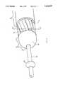
- FIG. 6is a detailed perspective view of a diffuser or rotor assembly of the present invention.
- FIG. 7is a cross-sectional view of the rotor assembly taken along line 7--7 of FIG. 6;
- FIG. 8is a sectional side view of the proximal portion of a catheter of FIG. 1;
- FIG. 9is a cross-sectional view of a second embodiment of the present invention in which the inner and outer catheter body overlap is adjustable;
- FIG. 10is a cross-sectional view of the embodiment of the invention shown in line 10--10 of FIG. 9;
- FIG. 11is a plan view of another embodiment of a catheter of the present invention.
- FIG. 12is a sectional view of the catheter of FIG. 11 taken along line 12--12;
- FIG. 13is a sectional view of the catheter of FIG. 11 taken along line 13--13 of FIG. 11;
- FIG. 14illustrates flow of fluid from the catheter diffusion manifold.
- the fluid-driven or rheologic catheter system of this inventionis designed to function as an intravascular unit for the effective dissolution and extraction of thrombus in the vasculature. Its structure permits controlled, pressurized fluid infusion at the distal tip of the catheter through, in a preferred practice, a helically slotted rotor or diffuser. Passage of the pressurized fluid through the rotor, in this preferred practice, induces rotational action of the rotor that disperses the fluid, in a uniform, generally proximally directed, controllable conical pattern. The dispersed fluid substantially atraumatically impacts surrounding vascular structure.
- a catheter assembly of this inventiontracks a guidewire (e.g., a 0.014 inch diameter guidewire) to facilitate vessel positioning for thrombus dissolution and extraction.
- a guidewiree.g., a 0.014 inch diameter guidewire
- a guidewire useable with this catheteris preferably silicone coated for improved vascular tracking and catheter interface at the close tolerance fit between the guidewire and the central lumen. Other coatings may be applied depending upon user preference.
- a catheter system of this inventionis intended for both coronary and peripheral vascular applications.
- the preferred clinical applicationis for the rheolytic dissolution and extraction of soft thrombus from the vasculature.
- This inventiontherefore, is to be understood to be particularly adapted to remove relatively soft, semi-fibrotic, non-calcified thrombus.
- the pressurized fluid dissolution zonenaturally adjusts to the vessel lumen size with no adverse effects upon the vessel wall layers. Effluent is removed from the vasculature to eliminate particulate embolization, to provide for improved vessel patency for immediate restoration of blood flow, and to expose other disease conditions that may require adjunctive interventional therapy.
- Catheter 10comprises outer and inner catheter bodies 12, 14, which are substantially coaxial.
- Catheter bodies 12 and 14have outer walls or sides 16, 18, respectively, with outer catheter body 12 also having an indicated inner catheter wall 20.
- Inner catheter body 14also has an inner catheter wall which cannot be seen in FIG. 1.
- Catheter bodies 12 and 14both have proximal ends 22, 22' and distal ends 24, 24' which overlap in at least some portion. As is shown, the distal portion or segment 24' of the inner catheter body wall extends beyond the distal portion 24 of the outer catheter body wall.
- catheter body walls 12, 14cooperate to define an annular lumen 26, (more completely discussed below) which permits fluid and dissolution products to be extracted from the site of occlusion removal.
- Diffusion manifold 28Located on the distal end 24' of inner catheter body wall 14 and in fluid communication with the interior thereof is a diffusion manifold 28.
- Diffusion manifold 28is fluidically coupled (via a central lumen not shown in FIG. 1) to the proximal end of catheter system 10 (e.g., at luer coupler 30) and to a plurality of substantially radially directed orifices (not shown in FIG. 1).
- Diffusion manifold 28comprises, in this embodiment, distal and proximal larger diameter segments 34, and 36, respectively, with a smaller diameter medial segment 38 therebetween. Larger diameter segments 34, 36 have a diffuser means 40 located therebetween.
- FIG. 1Located on the distal end 24' of inner catheter body wall 14 and in fluid communication with the interior thereof is a diffusion manifold 28.
- diffuser means 40is a cylindrical ring structure having a helical groove 42 embossed or cut in its exterior. Also in the embodiment shown, diffuser means 40 is rotated by fluid emerging from diffusion manifold 28. Thus, diffusion manifold 28, in this embodiment, comprises much of the structure which permits fluid to be delivered to a situs near or adjacent an occlusion.
- a second luer connector 50which is fluidically coupled (via the annular lumen) to an exterior aspiration source.
- fluidis both delivered to the distal end of the catheter system, is proximally directed and radially redirected, and fluid and debris are aspirated from the proximal end of the catheter.
- the rotatively directed fluid emerging from the diffusion manifoldeffects occlusion destruction with little or no vessel wall damage.
- catheter system 10tracks a guidewire 60.
- Guidewire 60passes axially through catheter 10 via the central lumen defined by inner catheter body inner wall 18.
- Guidewire 60is approximately coincident with the axis of the catheter system 10.
- Guidewire 60has an enlargement 62 thereon which prevents the guidewire from being completely drawn into the catheter system and which provides for retention of any structures aligned on the guidewire should they become detached.
- FIG. 2shows in section, the distal portion 24, 24' of catheter system shown in FIG. 1.
- the inner wall 70 of inner catheter body 14Proximally directed orifices 72 in header 28 are shown to direct their exiting pressurized fluid against diffuser 40.
- Inner wall 70 in conjunction with header or manifold 28defines central lumen 74 which is fluidically coupled through connector 30 to the proximal end of the catheter. Pressurized fluid introduced through connector 30 thus is delivered proximate or adjacent to the previously identified site of an occlusion.
- Header 28comprises as head section 80 into which fluid is delivered and a throat section 82 which is an extension of lumen 74. Disposed about or around a portion of throat section 82 is a rounded sleeve 84 which serves to retain the entire header 28 adjacent the extreme distal end of inner catheter body 14. Sleeve 84 further serves to retain diffuser 40 about throat section 82 and permits it to rotate thereabout.
- diffuser 40may be fixed to header 28 in which case it would not rotate when impinged by fluid exiting from orifice 72.
- the detailed design of header 28is not particularly critical. Many other structures which permit utilization of a fixed or rotatable diffuser are possible in view of the present invention.
- FIG. 2Also of note in FIG. 2 is the close tolerance fit between guidewire 60 and the reduced diameter section of central lumen 74 which is shown at interface 90.
- the close fit between guidewire 60 and central lumen 74 at interface 90substantially prevents fluid from exiting distally from the catheter system. Pressurized fluid in inner lumen 74 therefore is delivered substantially proximally from orifice(s) 72 rather than distally i.e, in the direction of arrow 78.
- the close tolerance fitmust be sufficiently close so as to prevent excessive proximal delivery of fluid (from central lumen 74) and yet permit the catheter system to pass over guidewire 60 to be positioned (and possibly repositioned) near an occlusion.
- Annular lumen 26is the structure into which dissolution products and fluid are aspirated through proximal manifold 50 to be removed from the occlusion site. Annular lumen 26 is fluidically coupled to an exterior aspiration (e.g., vacuum) source to draw fluid and debris therefrom.
- an exterior aspiratione.g., vacuum
- FIG. 3is a cross-sectional, enlarged view taken along line 3--3 of FIG. 1.
- the cross hatched area of the catheter sectionis the substantially solid proximal coupler body 200.
- Through coupler body 200is an axial lumen 202 which is or comprises a portion or extension of central lumen 74. Passing through lumen 202 is guidewire 60.
- FIG. 4is an enlarged sectional view of the catheter system taken along line 4--4 of FIG. 1.
- FIG. 4shows the internal details of the connection between luer coupler 50 and second coupler body 204.
- angular orifice 206By means of angular orifice 206 a merger (and fluidic coupling) between luer coupler 50 and annular lumen 26 is completed.
- the particular arrangement used to effectuate fluidic couplingis not critical as long as the required functional attributes of the catheter system, i.e., steerability, aspiration, inspiration, and rotational fluid dispersion, are obtained.
- FIG. 5is a cross sectional view of a catheter of this invention taken along line 5--5 of FIG. 1. Shown in FIG. 5 are tubular support segment 100 from luer coupler 50, exterior catheter body wall 12 which has inner and outer sides 16, 20, inner catheter wall 14 which has inner and outer sides 18 and 70, annular lumen 26, central lumen 74 and guidewire 60.
- luer coupler 50slightly overlaps part of the proximal portion of outer catheter body wall 16 and is affixed thereto by means of, for example, an adhesive.
- FIG. 6is an enlarged, perspective view of the header/diffuser portion of a catheter system of this invention.
- Helical grooves 42have been cut or formed into diffuser 40. The number, depth, orientation, and distribution of grooves (if grooves are employed) in the diffuser will determine the shape and dimension of the zone of dissolution. In the particular diffuser shown, helical grooves 42 are deeper toward the distal end of the system. The grooves become shallower and substantially merge with the surface or outer profile of the diffuser as they proceed toward the proximal end of the system and annular lumen 26. Essentially any groove configuration which directs fluid impinging thereon toward the obstruction to be treated is within the contemplation of the present invention. Generally speaking, such fluid will be radially directed and will rapidly rotate a rotatable diffuser.
- FIG. 7is a sectional view of a catheter of this invention taken along line 7--7 of FIG. 6.
- Diffuser 40 with helical grooves 42are shown in section.
- Medial segment 38supports diffuser 40 and permits it to be rotated by impinging fluid.
- manifold 28includes all of the structure to deliver fluid proximally and disperse it radially.
- the diffusercould be supported by the inner catheter body and not be connected to or with the manifold structure. Other variations within the above teaching will occur to one skilled in this art in light of this disclosure.
- this inventionprovides yet another significant advantage i.e., the ability to adjust the separation distance between the dissolution/diffuser segment from which fluid is delivered and the aspiration/annular lumen into which fluid and dissolution debris are withdrawn.
- Thisis accomplished by utilizing coupler bodies which are separate and are not coaxially fixed with respect to each other.
- coupler bodieswhich are separate and are not coaxially fixed with respect to each other.
- the separation between fluid delivery (at orifices 72) and fluid uptake (into annular lumen 26)can be adjusted.
- a single luer connector blockcould be utilized with couplers 30 and 50 inputing to the same connector block structure, albeit to different lumens.
- FIG. 8shows in section one connector block arrangement which is both substantially fluid tight and permits coupler bodies 200 and 204 to move axially with respect to each other.
- Proximal coupler body 200is shown to couple into the proximal end of coupler body 204 (at interface 110) and by means of O ring 210.
- O ring 210essentially prevents fluid from flowing through the coupler block interface which permitting the coupler blocks to be separated from each other.
- the coupler blocksare, in turn fixedly coupled to one or the other of the inner and outer catheter bodies such that separating the coupler block changes the extent of inner and outer catheter overlap.
- the compressed O ringis held in place by groove 212 and is compressed against the inside surface 214 to complete a fluid-tight connection.
- Threaded connector 220cooperates with coupler body 200 to create a substantially fluid tight fit (when completely inserted) around a guidewire. Seal 214 creates this fluid-tight fit as threated connector 220 is threaded into coupler block 200. As shown, central lumen 74 runs completely through blocks 200,204 and 220. By virtue of the reduction in diameter through threaded connector 220 and manifold 28, the previously mutually exclusive goals of a steerable, rheolytic catheter system is obtained.
- FIGS. 9 and 10illustrate a variation upon the above-described system wherein coupler bodies 200 and 204 are supported and held in axial relation (so as to permit their axial movement) by a cylindrical support 230 having therein a cooperating arcuate groove 232.
- Cylindrical support 230is substantially larger in diameter than eight of coupler bodies 200 or 204 and has groove 232 machined or formed along one side.
- the coupler bodiesmay then be slid into groove 232 to provide a proximal catheter configuration which is substantially integral and controllable with, for example, one hand.
- FIG. 10is a section view along line 10--10 of FIG. 9.
- FIG. 10clearly shows the sliding relationship between coupler body 204 and cylindrical support 230.
- This sliding relationshipsuggest many alternative means in which diffusion zone linear dimension may be adjusted.
- the handle meansdiscussed above could be attached to support 230 with trigger means coupled to the catheter segment which is to be moved. In this manner, convenient single-handed manipulation may be accomplished.
- FIGS. 11-13illustrate yet another embodiment of the present invention in which a radiopacity marker band 300 and an inflatable balloon 302 are utilized on the catheter body.
- Balloon 302is located on the outside wall 16 of outer catheter body 12. Such a balloon would be used to center the catheter system or to substantially restrict fluid flow down the vascular structure in which the catheter system is placed.
- Radiopacity marker bands or markerswhich are visible under fluoroscopic examination, are utilized to locate the otherwise transparent balloon structure during catheter placement.
- Marker band 300in this embodiment, is intended to indicate to the physician the location of balloon 302. Marker bands may be used elsewhere on (or within) the catheter to indicate to a user the location of significant structures in or on the catheter system.
- FIGS. 12 and 13are sectional views taken along line 12--12 and 13--13 of FIG. 11.
- FIGS. 12 and 13illustrate a variation to distal coupler body 204' and to outer catheter body 12 necessary to accommodate the balloon structure. That variation is to provide a fluid connector 55 which is utilized to inflate and deflate balloon 302.
- Connector 55is coupled to balloon 302 to permit fluid to be injected therein to inflate it.
- Through a third lumen 304(best seen in FIG. 13) relatively incompressible fluid can be used to inflate and deflate balloon 302.
- Lumen 304can be extruded into catheter body 12 in accordance with known techniques. Fluidic connection between connector 55 and balloon 302 is completed by means of skive 306 which intersects lumen 304.
- FIG. 14illustrates the flow of fluid from diffusion manifold 26 toward the proximal end of the catheter system.
- Fluid flow(and therefore the zone of turbulence or dissolution) is shown by arrows 310 and is produced by fluid exiting manifold 26 and impinging upon diffuser 40.
- envelope or shape of the turbulence zonegenerated. Presuming that guidewire 60 lies approximately along the axis of the device, the fluid envelope, zone or cone may be defined by the interior angle between the catheter axis and the fluid around the catheter which is non-turbulent.
- Arrow 312shows the approximate 40 degree interior angle subtended by the fluid emerging from the device (an impinging upon the diffuser) as would be generated in this embodiment. As noted above, it is control of this zone of destruction envelope which provides one of the many advantages of the present invention.
Landscapes
- Health & Medical Sciences (AREA)
- Life Sciences & Earth Sciences (AREA)
- Surgery (AREA)
- Heart & Thoracic Surgery (AREA)
- Engineering & Computer Science (AREA)
- Public Health (AREA)
- Biomedical Technology (AREA)
- Veterinary Medicine (AREA)
- Vascular Medicine (AREA)
- Animal Behavior & Ethology (AREA)
- General Health & Medical Sciences (AREA)
- Nuclear Medicine, Radiotherapy & Molecular Imaging (AREA)
- Medical Informatics (AREA)
- Molecular Biology (AREA)
- Anesthesiology (AREA)
- Hematology (AREA)
- Orthopedic Medicine & Surgery (AREA)
- Pulmonology (AREA)
- Surgical Instruments (AREA)
Abstract
Description
Claims (22)
Priority Applications (2)
| Application Number | Priority Date | Filing Date | Title |
|---|---|---|---|
| US08/134,089US5634897A (en) | 1993-10-08 | 1993-10-08 | Rheolytic occlusion removal catheter system and method |
| PCT/US1994/011343WO1995010232A1 (en) | 1993-10-08 | 1994-10-06 | Rheolytic occlusion removal catheter system and method |
Applications Claiming Priority (1)
| Application Number | Priority Date | Filing Date | Title |
|---|---|---|---|
| US08/134,089US5634897A (en) | 1993-10-08 | 1993-10-08 | Rheolytic occlusion removal catheter system and method |
Publications (1)
| Publication Number | Publication Date |
|---|---|
| US5634897Atrue US5634897A (en) | 1997-06-03 |
Family
ID=22461726
Family Applications (1)
| Application Number | Title | Priority Date | Filing Date |
|---|---|---|---|
| US08/134,089Expired - LifetimeUS5634897A (en) | 1993-10-08 | 1993-10-08 | Rheolytic occlusion removal catheter system and method |
Country Status (2)
| Country | Link |
|---|---|
| US (1) | US5634897A (en) |
| WO (1) | WO1995010232A1 (en) |
Cited By (110)
| Publication number | Priority date | Publication date | Assignee | Title |
|---|---|---|---|---|
| US5807330A (en)* | 1996-12-16 | 1998-09-15 | University Of Southern California | Angioplasty catheter |
| US5993410A (en)* | 1997-07-08 | 1999-11-30 | Cabot Technology Corporation | Adjustable probe |
| US6036682A (en) | 1997-12-02 | 2000-03-14 | Scimed Life Systems, Inc. | Catheter having a plurality of integral radiopaque bands |
| US6152909A (en)* | 1996-05-20 | 2000-11-28 | Percusurge, Inc. | Aspiration system and method |
| US6235007B1 (en)* | 1995-11-27 | 2001-05-22 | Therox, Inc. | Atraumatic fluid delivery devices |
| WO2001045572A1 (en)* | 1999-12-22 | 2001-06-28 | Boston Scientific Limited | Endoluminal occlusion-irrigation catheter and methods of use |
| US20010044632A1 (en)* | 1997-03-06 | 2001-11-22 | Scimed Life Systems, Inc. | Distal protection device and method |
| WO2001091844A1 (en)* | 2000-05-31 | 2001-12-06 | Kerberos Proximal Solutions, Inc. | Embolization protection system for vascular procedures |
| US20020022858A1 (en)* | 1999-07-30 | 2002-02-21 | Demond Jackson F. | Vascular device for emboli removal having suspension strut and methods of use |
| US6371970B1 (en) | 1999-07-30 | 2002-04-16 | Incept Llc | Vascular filter having articulation region and methods of use in the ascending aorta |
| US6371969B1 (en) | 1997-05-08 | 2002-04-16 | Scimed Life Systems, Inc. | Distal protection device and method |
| US6371971B1 (en) | 1999-11-15 | 2002-04-16 | Scimed Life Systems, Inc. | Guidewire filter and methods of use |
| US6454741B1 (en) | 1997-03-06 | 2002-09-24 | Medtronic Percusurge, Inc. | Aspiration method |
| US6530939B1 (en) | 1999-07-30 | 2003-03-11 | Incept, Llc | Vascular device having articulation region and methods of use |
| US20030055398A1 (en)* | 1997-03-06 | 2003-03-20 | Imran Mir A. | Methods for reducing distal embolization |
| US6537295B2 (en) | 2001-03-06 | 2003-03-25 | Scimed Life Systems, Inc. | Wire and lock mechanism |
| US6544279B1 (en) | 2000-08-09 | 2003-04-08 | Incept, Llc | Vascular device for emboli, thrombus and foreign body removal and methods of use |
| US6544280B1 (en) | 1999-02-24 | 2003-04-08 | Scimed Life Systems, Inc. | Intravascular filter and method |
| US20030083692A1 (en)* | 2001-10-29 | 2003-05-01 | Scimed Life Systems, Inc. | Distal protection device and method of use thereof |
| US6569148B2 (en) | 1996-05-20 | 2003-05-27 | Medtronic Ave, Inc. | Methods for emboli containment |
| US6589263B1 (en) | 1999-07-30 | 2003-07-08 | Incept Llc | Vascular device having one or more articulation regions and methods of use |
| US6605074B2 (en) | 1999-03-16 | 2003-08-12 | Medtronic Ave, Inc. | Method for containing and removing occlusions in the carotid arteries |
| US6616679B1 (en) | 1999-07-30 | 2003-09-09 | Incept, Llc | Rapid exchange vascular device for emboli and thrombus removal and methods of use |
| US6616681B2 (en) | 2000-10-05 | 2003-09-09 | Scimed Life Systems, Inc. | Filter delivery and retrieval device |
| US6620182B1 (en) | 1999-07-30 | 2003-09-16 | Incept Llc | Vascular filter having articulation region and methods of use in the ascending aorta |
| US6620148B1 (en) | 1999-08-04 | 2003-09-16 | Scimed Life Systems, Inc. | Filter flush system and methods of use |
| US20030187475A1 (en)* | 1997-05-08 | 2003-10-02 | Scimed Life Systems, Inc | Percutaneous catheter and guidewire having filter and medical device deployment capabilities |
| US20030208222A1 (en)* | 1996-05-20 | 2003-11-06 | Gholam-Reza Zadno-Azizi | Method and apparatus for emboli containment |
| US6652505B1 (en) | 1999-08-03 | 2003-11-25 | Scimed Life Systems Inc. | Guided filter with support wire and methods of use |
| US6663651B2 (en) | 2001-01-16 | 2003-12-16 | Incept Llc | Systems and methods for vascular filter retrieval |
| US6673090B2 (en) | 1999-08-04 | 2004-01-06 | Scimed Life Systems, Inc. | Percutaneous catheter and guidewire for filtering during ablation of myocardial or vascular tissue |
| US6689151B2 (en) | 2001-01-25 | 2004-02-10 | Scimed Life Systems, Inc. | Variable wall thickness for delivery sheath housing |
| US20040073163A1 (en)* | 2001-07-30 | 2004-04-15 | Scimed Life Systems, Inc. | Chronic total occlusion device with variable stiffness shaft |
| US20040122416A1 (en)* | 2002-12-18 | 2004-06-24 | Medical Components, Inc. | Locking guidewire straightener |
| US6755847B2 (en) | 2001-10-05 | 2004-06-29 | Scimed Life Systems, Inc. | Emboli capturing device and method of manufacture therefor |
| US20040193146A1 (en)* | 2001-02-15 | 2004-09-30 | Endo Via Medical, Inc. | Robotically controlled surgical instruments |
| US20040193099A1 (en)* | 2001-07-17 | 2004-09-30 | Macmahon John M. | Fluid exchange system for controlled and localized irrigation and aspiration |
| US20050004517A1 (en)* | 2000-06-02 | 2005-01-06 | Courtney Brian K. | Embolization protection system for vascular procedures |
| US20050004594A1 (en)* | 2003-07-02 | 2005-01-06 | Jeffrey Nool | Devices and methods for aspirating from filters |
| US6849068B1 (en) | 1997-03-06 | 2005-02-01 | Medtronic Ave, Inc. | Aspiration catheter |
| US20050049572A1 (en)* | 2002-12-18 | 2005-03-03 | Medical Components, Inc. | Locking guidewire straightener |
| US20050216033A1 (en)* | 2001-02-15 | 2005-09-29 | Endo Via Medical Inc. | Robotically controlled medical instrument with a flexible section |
| US6951570B2 (en) | 2001-07-02 | 2005-10-04 | Rubicon Medical, Inc. | Methods, systems, and devices for deploying a filter from a filter device |
| US6962598B2 (en) | 2001-07-02 | 2005-11-08 | Rubicon Medical, Inc. | Methods, systems, and devices for providing embolic protection |
| US20060025806A1 (en)* | 2001-07-24 | 2006-02-02 | Jeffrey Krolik | Apparatus and methods for aspirating emboli |
| US6997939B2 (en) | 2001-07-02 | 2006-02-14 | Rubicon Medical, Inc. | Methods, systems, and devices for deploying an embolic protection filter |
| US7008535B1 (en) | 2000-08-04 | 2006-03-07 | Wayne State University | Apparatus for oxygenating wastewater |
| US20060058838A1 (en)* | 2004-09-10 | 2006-03-16 | Arani Bose | System and method for treating ischemic stroke |
| US7052500B2 (en) | 2001-10-19 | 2006-05-30 | Scimed Life Systems, Inc. | Embolus extractor |
| US7094249B1 (en) | 1997-03-06 | 2006-08-22 | Boston Scientific Scimed, Inc. | Distal protection device and method |
| US20070032808A1 (en)* | 2005-08-03 | 2007-02-08 | Azam Anwar | System and method for addressing total occlusion in a vascular environment |
| US7204464B2 (en) | 2005-01-21 | 2007-04-17 | Boston Scientific Scimed, Inc. | Medical wire holder |
| US20070239105A1 (en)* | 2001-02-15 | 2007-10-11 | Hansen Medical, Inc. | Coaxial catheter system |
| US20070239170A1 (en)* | 1998-02-24 | 2007-10-11 | Brock David L | Flexible instrument |
| US20070250073A1 (en)* | 1998-02-24 | 2007-10-25 | Brock David L | Flexible instrument |
| US7320697B2 (en) | 1999-07-30 | 2008-01-22 | Boston Scientific Scimed, Inc. | One piece loop and coil |
| US20080188831A1 (en)* | 2007-02-06 | 2008-08-07 | Possis Medical, Inc. | Miniature flexible thrombectomy catheter |
| US20080300532A1 (en)* | 2004-12-10 | 2008-12-04 | Possis Medical, Inc. | Enhanced cross stream mechanical thrombectomy catheter |
| US20080312672A1 (en)* | 2007-06-12 | 2008-12-18 | Possis Medical, Inc. | Forwardly directed fluid jet crossing catheter |
| US20080319386A1 (en)* | 2007-06-20 | 2008-12-25 | Possis Medical, Inc. | Forwardly directable fluid jet crossing catheter |
| US7473265B2 (en) | 2004-03-15 | 2009-01-06 | Boston Scientific Scimed, Inc. | Filter media and methods of manufacture |
| US7478465B1 (en) | 2005-01-10 | 2009-01-20 | Boston Scientific Scimed, Inc. | Method of securing a restraining member on a medical device |
| US20090156983A1 (en)* | 2007-12-17 | 2009-06-18 | Medrad, Inc. | Rheolytic thrombectomy catheter with self-inflating distal balloon |
| US7563272B2 (en) | 1999-07-16 | 2009-07-21 | Boston Scientific Scimed, Inc. | Emboli filtration system and methods of use |
| US7572244B2 (en) | 2004-08-02 | 2009-08-11 | Medrad, Inc. | Miniature cross stream thrombectomy catheter |
| US7594926B2 (en) | 2001-11-09 | 2009-09-29 | Boston Scientific Scimed, Inc. | Methods, systems and devices for delivering stents |
| US7621904B2 (en) | 2004-10-21 | 2009-11-24 | Boston Scientific Scimed, Inc. | Catheter with a pre-shaped distal tip |
| US7651514B2 (en) | 2003-12-11 | 2010-01-26 | Boston Scientific Scimed, Inc. | Nose rider improvement for filter exchange and methods of use |
| US7708770B2 (en) | 2001-11-09 | 2010-05-04 | Boston Scientific Scimed, Inc. | Stent delivery device with embolic protection |
| US7714217B2 (en) | 2007-12-21 | 2010-05-11 | Innovatech, Llc | Marked precoated strings and method of manufacturing same |
| US7713190B2 (en) | 1998-02-24 | 2010-05-11 | Hansen Medical, Inc. | Flexible instrument |
| US7780611B2 (en) | 2003-05-01 | 2010-08-24 | Boston Scientific Scimed, Inc. | Medical instrument with controlled torque transmission |
| US7794472B2 (en) | 2004-08-11 | 2010-09-14 | Boston Scientific Scimed, Inc. | Single wire intravascular filter |
| US7811623B2 (en) | 2007-12-21 | 2010-10-12 | Innovatech, Llc | Marked precoated medical device and method of manufacturing same |
| US7875050B2 (en) | 1997-09-30 | 2011-01-25 | Target Therapeutics, Inc. | Mechanical clot treatment device |
| US7879022B2 (en) | 1998-02-06 | 2011-02-01 | Medrad, Inc. | Rapid exchange fluid jet thrombectomy device and method |
| US7996974B2 (en) | 2007-02-06 | 2011-08-16 | Medrad, Inc. | Method of manufacturing a miniature flexible thrombectomy catheter |
| US7998163B2 (en) | 2002-10-03 | 2011-08-16 | Boston Scientific Scimed, Inc. | Expandable retrieval device |
| US8038696B2 (en) | 2004-12-06 | 2011-10-18 | Boston Scientific Scimed, Inc. | Sheath for use with an embolic protection filter |
| US8048471B2 (en) | 2007-12-21 | 2011-11-01 | Innovatech, Llc | Marked precoated medical device and method of manufacturing same |
| US8162878B2 (en) | 2005-12-05 | 2012-04-24 | Medrad, Inc. | Exhaust-pressure-operated balloon catheter system |
| US8231927B2 (en) | 2007-12-21 | 2012-07-31 | Innovatech, Llc | Marked precoated medical device and method of manufacturing same |
| US8231926B2 (en) | 2007-12-21 | 2012-07-31 | Innovatech, Llc | Marked precoated medical device and method of manufacturing same |
| US8236024B2 (en) | 2001-02-20 | 2012-08-07 | Boston Scientific Scimed, Inc. | Low profile emboli capture device |
| US8241315B2 (en) | 2004-06-24 | 2012-08-14 | Boston Scientific Scimed, Inc. | Apparatus and method for treating occluded vasculature |
| US8414505B1 (en) | 2001-02-15 | 2013-04-09 | Hansen Medical, Inc. | Catheter driver system |
| US8414598B2 (en) | 1998-02-24 | 2013-04-09 | Hansen Medical, Inc. | Flexible instrument |
| US8439878B2 (en) | 2007-12-26 | 2013-05-14 | Medrad, Inc. | Rheolytic thrombectomy catheter with self-inflating proximal balloon with drug infusion capabilities |
| US8444669B2 (en) | 2008-12-15 | 2013-05-21 | Boston Scientific Scimed, Inc. | Embolic filter delivery system and method |
| US8468678B2 (en) | 2002-10-02 | 2013-06-25 | Boston Scientific Scimed, Inc. | Expandable retrieval device |
| US8480629B2 (en) | 2005-01-28 | 2013-07-09 | Boston Scientific Scimed, Inc. | Universal utility board for use with medical devices and methods of use |
| US8535344B2 (en) | 2003-09-12 | 2013-09-17 | Rubicon Medical, Inc. | Methods, systems, and devices for providing embolic protection and removing embolic material |
| US8647294B2 (en) | 2008-03-20 | 2014-02-11 | Medrad, Inc. | Direct stream hydrodynamic catheter system |
| US8663259B2 (en) | 2010-05-13 | 2014-03-04 | Rex Medical L.P. | Rotational thrombectomy wire |
| US8764779B2 (en) | 2010-05-13 | 2014-07-01 | Rex Medical, L.P. | Rotational thrombectomy wire |
| US8821478B2 (en) | 2011-03-04 | 2014-09-02 | Boston Scientific Scimed, Inc. | Catheter with variable stiffness |
| US8900652B1 (en) | 2011-03-14 | 2014-12-02 | Innovatech, Llc | Marked fluoropolymer surfaces and method of manufacturing same |
| US9023070B2 (en) | 2010-05-13 | 2015-05-05 | Rex Medical, L.P. | Rotational thrombectomy wire coupler |
| US9586023B2 (en) | 1998-02-06 | 2017-03-07 | Boston Scientific Limited | Direct stream hydrodynamic catheter system |
| US20170087339A1 (en)* | 2015-09-25 | 2017-03-30 | Mark Taber | Guide wires, catheters, and guide wire catheter systems and methods |
| US9655633B2 (en) | 2004-09-10 | 2017-05-23 | Penumbra, Inc. | System and method for treating ischemic stroke |
| US9795406B2 (en) | 2010-05-13 | 2017-10-24 | Rex Medical, L.P. | Rotational thrombectomy wire |
| CN110582243A (en)* | 2017-05-03 | 2019-12-17 | 美敦力瓦斯科尔勒公司 | Tissue Removal Catheter with Guide Wire Isolation Bush |
| CN112842459A (en)* | 2020-12-30 | 2021-05-28 | 武汉佑康科技有限公司 | Clear stone pipe structure |
| US11020174B2 (en) | 2016-10-17 | 2021-06-01 | Biosense Webster (Israel) Ltd. | Catheter with angled irrigation holes |
| US11129702B2 (en) | 2018-05-09 | 2021-09-28 | Boston Scientific Scimed, Inc. | Pedal access embolic filtering sheath |
| US11690645B2 (en) | 2017-05-03 | 2023-07-04 | Medtronic Vascular, Inc. | Tissue-removing catheter |
| US20230320576A1 (en)* | 2017-10-03 | 2023-10-12 | Research Development Foundation | Systems and methods for coronary occlusion treatment |
| US11819236B2 (en) | 2019-05-17 | 2023-11-21 | Medtronic Vascular, Inc. | Tissue-removing catheter |
| US12096951B2 (en) | 2011-10-05 | 2024-09-24 | Penumbra, Inc. | System and method for treating ischemic stroke |
Families Citing this family (5)
| Publication number | Priority date | Publication date | Assignee | Title |
|---|---|---|---|---|
| US6635027B1 (en) | 1997-05-19 | 2003-10-21 | Micro Therepeutics, Inc. | Method and apparatus for intramural delivery of a substance |
| US6063069A (en)* | 1997-05-19 | 2000-05-16 | Micro Therapeutics Inc. | Method and apparatus for power lysis of a thrombus |
| US6224570B1 (en)* | 1998-02-06 | 2001-05-01 | Possis Medical, Inc. | Rheolytic thrombectomy catheter and method of using same |
| US5989210A (en)* | 1998-02-06 | 1999-11-23 | Possis Medical, Inc. | Rheolytic thrombectomy catheter and method of using same |
| US20210220548A1 (en)* | 2018-06-13 | 2021-07-22 | Np Medical Inc. | Self-flushing ports |
Citations (13)
| Publication number | Priority date | Publication date | Assignee | Title |
|---|---|---|---|---|
| US4445509A (en)* | 1982-02-04 | 1984-05-01 | Auth David C | Method and apparatus for removal of enclosed abnormal deposits |
| US4589412A (en)* | 1984-01-03 | 1986-05-20 | Intravascular Surgical Instruments, Inc. | Method and apparatus for surgically removing remote deposits |
| US4631052A (en)* | 1984-01-03 | 1986-12-23 | Intravascular Surgical Instruments, Inc. | Method and apparatus for surgically removing remote deposits |
| US4747821A (en)* | 1986-10-22 | 1988-05-31 | Intravascular Surgical Instruments, Inc. | Catheter with high speed moving working head |
| US4749376A (en)* | 1986-10-24 | 1988-06-07 | Intravascular Surgical Instruments, Inc. | Reciprocating working head catheter |
| US4784636A (en)* | 1987-04-30 | 1988-11-15 | Schneider-Shiley (U.S.A.) Inc. | Balloon atheroectomy catheter |
| US4790813A (en)* | 1984-12-17 | 1988-12-13 | Intravascular Surgical Instruments, Inc. | Method and apparatus for surgically removing remote deposits |
| US4795438A (en)* | 1987-05-13 | 1989-01-03 | Intravascular Surgical Instruments, Inc. | Method and apparatus for forming a restriction in a vessel, duct or lumen |
| US4857045A (en)* | 1987-04-30 | 1989-08-15 | Schneider (Usa) Inc., A Pfizer Company | Atherectomy catheter |
| US4950238A (en)* | 1988-07-07 | 1990-08-21 | Clarence E. Sikes | Hydro-rotary vascular catheter |
| US5135484A (en)* | 1990-05-09 | 1992-08-04 | Pioneering Technologies, Inc. | Method of removing plaque from vessels |
| US5135482A (en)* | 1985-12-31 | 1992-08-04 | Arnold Neracher | Hydrodynamic device for the elimination of an organic deposit obstructing a vessel of a human body |
| US5273526A (en)* | 1991-06-21 | 1993-12-28 | Lake Region Manufacturing Company, Inc. | Vascular occulusion removal devices and method |
- 1993
- 1993-10-08USUS08/134,089patent/US5634897A/ennot_activeExpired - Lifetime
- 1994
- 1994-10-06WOPCT/US1994/011343patent/WO1995010232A1/enactiveApplication Filing
Patent Citations (13)
| Publication number | Priority date | Publication date | Assignee | Title |
|---|---|---|---|---|
| US4445509A (en)* | 1982-02-04 | 1984-05-01 | Auth David C | Method and apparatus for removal of enclosed abnormal deposits |
| US4589412A (en)* | 1984-01-03 | 1986-05-20 | Intravascular Surgical Instruments, Inc. | Method and apparatus for surgically removing remote deposits |
| US4631052A (en)* | 1984-01-03 | 1986-12-23 | Intravascular Surgical Instruments, Inc. | Method and apparatus for surgically removing remote deposits |
| US4790813A (en)* | 1984-12-17 | 1988-12-13 | Intravascular Surgical Instruments, Inc. | Method and apparatus for surgically removing remote deposits |
| US5135482A (en)* | 1985-12-31 | 1992-08-04 | Arnold Neracher | Hydrodynamic device for the elimination of an organic deposit obstructing a vessel of a human body |
| US4747821A (en)* | 1986-10-22 | 1988-05-31 | Intravascular Surgical Instruments, Inc. | Catheter with high speed moving working head |
| US4749376A (en)* | 1986-10-24 | 1988-06-07 | Intravascular Surgical Instruments, Inc. | Reciprocating working head catheter |
| US4784636A (en)* | 1987-04-30 | 1988-11-15 | Schneider-Shiley (U.S.A.) Inc. | Balloon atheroectomy catheter |
| US4857045A (en)* | 1987-04-30 | 1989-08-15 | Schneider (Usa) Inc., A Pfizer Company | Atherectomy catheter |
| US4795438A (en)* | 1987-05-13 | 1989-01-03 | Intravascular Surgical Instruments, Inc. | Method and apparatus for forming a restriction in a vessel, duct or lumen |
| US4950238A (en)* | 1988-07-07 | 1990-08-21 | Clarence E. Sikes | Hydro-rotary vascular catheter |
| US5135484A (en)* | 1990-05-09 | 1992-08-04 | Pioneering Technologies, Inc. | Method of removing plaque from vessels |
| US5273526A (en)* | 1991-06-21 | 1993-12-28 | Lake Region Manufacturing Company, Inc. | Vascular occulusion removal devices and method |
Non-Patent Citations (4)
| Title |
|---|
| "A Rheolytic System for Percutaneous Coronary and Peripheal Plaque Removal," Angiology, vol. 42, No. 2, Feb. '91, p. 90. |
| "Rheolytic Catheter for Percutaneous Removal of Thrombus," Radiology, vol. 182, No. 1, Jan. 1992, pp. 263-267. |
| A Rheolytic System for Percutaneous Coronary and Peripheal Plaque Removal, Angiology, vol. 42, No. 2, Feb. 91, p. 90.* |
| Rheolytic Catheter for Percutaneous Removal of Thrombus, Radiology, vol. 182, No. 1, Jan. 1992, pp. 263 267.* |
Cited By (223)
| Publication number | Priority date | Publication date | Assignee | Title |
|---|---|---|---|---|
| US6235007B1 (en)* | 1995-11-27 | 2001-05-22 | Therox, Inc. | Atraumatic fluid delivery devices |
| US6558502B2 (en) | 1995-11-27 | 2003-05-06 | Therox, Inc. | Method for forming atraumatic fluid delivery device |
| US6398773B1 (en) | 1996-05-20 | 2002-06-04 | Medtronic Percusurge, Inc | Aspiration system and method |
| US20030208222A1 (en)* | 1996-05-20 | 2003-11-06 | Gholam-Reza Zadno-Azizi | Method and apparatus for emboli containment |
| US6569148B2 (en) | 1996-05-20 | 2003-05-27 | Medtronic Ave, Inc. | Methods for emboli containment |
| US6152909A (en)* | 1996-05-20 | 2000-11-28 | Percusurge, Inc. | Aspiration system and method |
| US20070060942A2 (en)* | 1996-05-20 | 2007-03-15 | Gholam-Reza Zadno-Azizi | Method and Apparatus for Emboli Containment |
| US5807330A (en)* | 1996-12-16 | 1998-09-15 | University Of Southern California | Angioplasty catheter |
| US20010044632A1 (en)* | 1997-03-06 | 2001-11-22 | Scimed Life Systems, Inc. | Distal protection device and method |
| US6805692B2 (en) | 1997-03-06 | 2004-10-19 | Medtronic Ave, Inc. | Aspiration method |
| US6849068B1 (en) | 1997-03-06 | 2005-02-01 | Medtronic Ave, Inc. | Aspiration catheter |
| US7033344B2 (en) | 1997-03-06 | 2006-04-25 | Medtronic Vascular, Inc. | Methods for reducing distal embolization |
| US6652480B1 (en) | 1997-03-06 | 2003-11-25 | Medtronic Ave., Inc. | Methods for reducing distal embolization |
| US6454741B1 (en) | 1997-03-06 | 2002-09-24 | Medtronic Percusurge, Inc. | Aspiration method |
| US7094249B1 (en) | 1997-03-06 | 2006-08-22 | Boston Scientific Scimed, Inc. | Distal protection device and method |
| US20030055398A1 (en)* | 1997-03-06 | 2003-03-20 | Imran Mir A. | Methods for reducing distal embolization |
| US6964673B2 (en) | 1997-05-08 | 2005-11-15 | Scimed Life Systems, Inc. | Percutaneous catheter and guidewire having filter and medical device deployment capabilities |
| US6676682B1 (en) | 1997-05-08 | 2004-01-13 | Scimed Life Systems, Inc. | Percutaneous catheter and guidewire having filter and medical device deployment capabilities |
| US6371969B1 (en) | 1997-05-08 | 2002-04-16 | Scimed Life Systems, Inc. | Distal protection device and method |
| US7691123B2 (en) | 1997-05-08 | 2010-04-06 | Boston Scientific Scimed, Inc. | Percutaneous catheter and guidewire having filter and medical device deployment capabilities |
| US20030187475A1 (en)* | 1997-05-08 | 2003-10-02 | Scimed Life Systems, Inc | Percutaneous catheter and guidewire having filter and medical device deployment capabilities |
| US5993410A (en)* | 1997-07-08 | 1999-11-30 | Cabot Technology Corporation | Adjustable probe |
| US7875050B2 (en) | 1997-09-30 | 2011-01-25 | Target Therapeutics, Inc. | Mechanical clot treatment device |
| US8486104B2 (en) | 1997-09-30 | 2013-07-16 | Stryker Corporation | Mechanical clot treatment device with distal filter |
| US6036682A (en) | 1997-12-02 | 2000-03-14 | Scimed Life Systems, Inc. | Catheter having a plurality of integral radiopaque bands |
| US7879022B2 (en) | 1998-02-06 | 2011-02-01 | Medrad, Inc. | Rapid exchange fluid jet thrombectomy device and method |
| US10321932B2 (en) | 1998-02-06 | 2019-06-18 | Boston Scientific Limited | Direct stream hydrodynamic catheter system |
| US9586023B2 (en) | 1998-02-06 | 2017-03-07 | Boston Scientific Limited | Direct stream hydrodynamic catheter system |
| US7918861B2 (en) | 1998-02-24 | 2011-04-05 | Hansen Medical, Inc. | Flexible instrument |
| US8114097B2 (en) | 1998-02-24 | 2012-02-14 | Hansen Medical, Inc. | Flexible instrument |
| US7371210B2 (en) | 1998-02-24 | 2008-05-13 | Hansen Medical, Inc. | Flexible instrument |
| US8414598B2 (en) | 1998-02-24 | 2013-04-09 | Hansen Medical, Inc. | Flexible instrument |
| US20070255291A1 (en)* | 1998-02-24 | 2007-11-01 | Brock David L | Flexible instrument |
| US20070250074A1 (en)* | 1998-02-24 | 2007-10-25 | Brock David L | Flexible instrument |
| US20070250073A1 (en)* | 1998-02-24 | 2007-10-25 | Brock David L | Flexible instrument |
| US20070239170A1 (en)* | 1998-02-24 | 2007-10-11 | Brock David L | Flexible instrument |
| US7905828B2 (en) | 1998-02-24 | 2011-03-15 | Hansen Medical, Inc. | Flexible instrument |
| US7931586B2 (en) | 1998-02-24 | 2011-04-26 | Hansen Medical, Inc. | Flexible instrument |
| US7713190B2 (en) | 1998-02-24 | 2010-05-11 | Hansen Medical, Inc. | Flexible instrument |
| US20070260115A1 (en)* | 1998-02-24 | 2007-11-08 | Brock David L | Flexible instrument |
| US7775972B2 (en) | 1998-02-24 | 2010-08-17 | Hansen Medical, Inc. | Flexible instrument |
| US7867241B2 (en) | 1998-02-24 | 2011-01-11 | Hansen Medical, Inc. | Flexible instrument |
| US9119706B2 (en) | 1999-02-24 | 2015-09-01 | Boston Scientific Scimed Inc. | Intravascular filter and method |
| US8303618B2 (en) | 1999-02-24 | 2012-11-06 | Boston Scientific Scimed, Inc. | Intravascular filter and method |
| US6544280B1 (en) | 1999-02-24 | 2003-04-08 | Scimed Life Systems, Inc. | Intravascular filter and method |
| US7618433B2 (en) | 1999-02-24 | 2009-11-17 | Boston Scientific Scimed, Inc. | Intravascular filter and method |
| US6790204B2 (en) | 1999-03-16 | 2004-09-14 | Medtronic Vascular, Inc. | Method for containing and removing occlusions in the carotid arteries |
| US6605074B2 (en) | 1999-03-16 | 2003-08-12 | Medtronic Ave, Inc. | Method for containing and removing occlusions in the carotid arteries |
| US7563272B2 (en) | 1999-07-16 | 2009-07-21 | Boston Scientific Scimed, Inc. | Emboli filtration system and methods of use |
| US7699866B2 (en) | 1999-07-16 | 2010-04-20 | Boston Scientific Scimed, Inc. | Emboli filtration system and methods of use |
| US6620182B1 (en) | 1999-07-30 | 2003-09-16 | Incept Llc | Vascular filter having articulation region and methods of use in the ascending aorta |
| US6530939B1 (en) | 1999-07-30 | 2003-03-11 | Incept, Llc | Vascular device having articulation region and methods of use |
| US6589263B1 (en) | 1999-07-30 | 2003-07-08 | Incept Llc | Vascular device having one or more articulation regions and methods of use |
| US7410491B2 (en) | 1999-07-30 | 2008-08-12 | Incept Llc | Vascular device for emboli, thrombus and foreign body removal and methods of use |
| US9283066B2 (en) | 1999-07-30 | 2016-03-15 | Incept Llc | Vascular device for emboli, thrombus and foreign body removal and methods of use |
| US7320697B2 (en) | 1999-07-30 | 2008-01-22 | Boston Scientific Scimed, Inc. | One piece loop and coil |
| US8617201B2 (en) | 1999-07-30 | 2013-12-31 | Incept Llc | Vascular device for emboli, thrombus and foreign body removal and methods of use |
| USRE43902E1 (en) | 1999-07-30 | 2013-01-01 | Incept, Llc | Vascular device for emboli, thrombus and foreign body removal and methods of use |
| USRE43882E1 (en) | 1999-07-30 | 2012-12-25 | Incept, Llc | Vascular device for emboli, thrombus and foreign body removal and methods of use |
| US6616679B1 (en) | 1999-07-30 | 2003-09-09 | Incept, Llc | Rapid exchange vascular device for emboli and thrombus removal and methods of use |
| US20020022858A1 (en)* | 1999-07-30 | 2002-02-21 | Demond Jackson F. | Vascular device for emboli removal having suspension strut and methods of use |
| US6371970B1 (en) | 1999-07-30 | 2002-04-16 | Incept Llc | Vascular filter having articulation region and methods of use in the ascending aorta |
| US6652505B1 (en) | 1999-08-03 | 2003-11-25 | Scimed Life Systems Inc. | Guided filter with support wire and methods of use |
| US7235061B2 (en) | 1999-08-03 | 2007-06-26 | Boston Scientific Scimed, Inc. | Guided filter with support wire and methods of use |
| US6620148B1 (en) | 1999-08-04 | 2003-09-16 | Scimed Life Systems, Inc. | Filter flush system and methods of use |
| US7326226B2 (en) | 1999-08-04 | 2008-02-05 | Boston Scientific Scimed, Inc. | Percutaneous catheter and guidewire for filtering during ablation of myocardial or vascular tissue |
| US8444665B2 (en) | 1999-08-04 | 2013-05-21 | Boston Scientific Scimed, Inc. | Filter flush system and methods of use |
| US6673090B2 (en) | 1999-08-04 | 2004-01-06 | Scimed Life Systems, Inc. | Percutaneous catheter and guidewire for filtering during ablation of myocardial or vascular tissue |
| US20040006370A1 (en)* | 1999-08-04 | 2004-01-08 | Scimed Life Systems, Inc | Filter flush system and methods of use |
| US6371971B1 (en) | 1999-11-15 | 2002-04-16 | Scimed Life Systems, Inc. | Guidewire filter and methods of use |
| WO2001045572A1 (en)* | 1999-12-22 | 2001-06-28 | Boston Scientific Limited | Endoluminal occlusion-irrigation catheter and methods of use |
| US7108677B2 (en) | 2000-05-31 | 2006-09-19 | Kerberos Proximal Solutions, Inc. | Embolization protection system for vascular procedures |
| WO2001091844A1 (en)* | 2000-05-31 | 2001-12-06 | Kerberos Proximal Solutions, Inc. | Embolization protection system for vascular procedures |
| US8435225B2 (en) | 2000-06-02 | 2013-05-07 | Fox Hollow Technologies, Inc. | Embolization protection system for vascular procedures |
| US20050004517A1 (en)* | 2000-06-02 | 2005-01-06 | Courtney Brian K. | Embolization protection system for vascular procedures |
| US7008535B1 (en) | 2000-08-04 | 2006-03-07 | Wayne State University | Apparatus for oxygenating wastewater |
| US7294278B2 (en) | 2000-08-04 | 2007-11-13 | Wayne State University | Method for oxygenating wastewater |
| US6544279B1 (en) | 2000-08-09 | 2003-04-08 | Incept, Llc | Vascular device for emboli, thrombus and foreign body removal and methods of use |
| US7229464B2 (en) | 2000-10-05 | 2007-06-12 | Scimed Life Systems, Inc. | Filter delivery and retrieval device |
| US6616681B2 (en) | 2000-10-05 | 2003-09-09 | Scimed Life Systems, Inc. | Filter delivery and retrieval device |
| US6663651B2 (en) | 2001-01-16 | 2003-12-16 | Incept Llc | Systems and methods for vascular filter retrieval |
| US20040082968A1 (en)* | 2001-01-16 | 2004-04-29 | Incept Llc | Systems and methods for vascular filter retrieval |
| US8460336B2 (en) | 2001-01-16 | 2013-06-11 | Incept Llc | Systems and methods for vascular filter retrieval |
| US7097652B2 (en) | 2001-01-25 | 2006-08-29 | Scimed Life Systems, Inc. | Variable wall thickness for delivery sheath housing |
| US6689151B2 (en) | 2001-01-25 | 2004-02-10 | Scimed Life Systems, Inc. | Variable wall thickness for delivery sheath housing |
| US7819884B2 (en) | 2001-02-15 | 2010-10-26 | Hansen Medical, Inc. | Robotically controlled medical instrument |
| US7744608B2 (en) | 2001-02-15 | 2010-06-29 | Hansen Medical, Inc. | Robotically controlled medical instrument |
| US20080177284A1 (en)* | 2001-02-15 | 2008-07-24 | Hansen Medical, Inc. | Robotically controlled medical instrument |
| US7955316B2 (en) | 2001-02-15 | 2011-06-07 | Han Sen Medical, Inc. | Coaxial catheter system |
| US10695536B2 (en) | 2001-02-15 | 2020-06-30 | Auris Health, Inc. | Catheter driver system |
| US8187229B2 (en) | 2001-02-15 | 2012-05-29 | Hansen Medical, Inc. | Coaxial catheter system |
| US7854738B2 (en) | 2001-02-15 | 2010-12-21 | Hansen Medical, Inc. | Robotically controlled medical instrument |
| US20080119824A1 (en)* | 2001-02-15 | 2008-05-22 | Hansen Medical, Inc. | Coaxial catheter system |
| US20070239105A1 (en)* | 2001-02-15 | 2007-10-11 | Hansen Medical, Inc. | Coaxial catheter system |
| US20040193146A1 (en)* | 2001-02-15 | 2004-09-30 | Endo Via Medical, Inc. | Robotically controlled surgical instruments |
| US7766894B2 (en) | 2001-02-15 | 2010-08-03 | Hansen Medical, Inc. | Coaxial catheter system |
| US7727185B2 (en) | 2001-02-15 | 2010-06-01 | Hansen Medical, Inc. | Coaxial catheter system |
| US7699835B2 (en) | 2001-02-15 | 2010-04-20 | Hansen Medical, Inc. | Robotically controlled surgical instruments |
| US8603068B2 (en) | 2001-02-15 | 2013-12-10 | Hansen Medical Inc. | Coaxial catheter system |
| US8414505B1 (en) | 2001-02-15 | 2013-04-09 | Hansen Medical, Inc. | Catheter driver system |
| US7608083B2 (en) | 2001-02-15 | 2009-10-27 | Hansen Medical, Inc. | Robotically controlled medical instrument with a flexible section |
| US20050216033A1 (en)* | 2001-02-15 | 2005-09-29 | Endo Via Medical Inc. | Robotically controlled medical instrument with a flexible section |
| US8236024B2 (en) | 2001-02-20 | 2012-08-07 | Boston Scientific Scimed, Inc. | Low profile emboli capture device |
| US6991642B2 (en) | 2001-03-06 | 2006-01-31 | Scimed Life Systems, Inc. | Wire and lock mechanism |
| US6537295B2 (en) | 2001-03-06 | 2003-03-25 | Scimed Life Systems, Inc. | Wire and lock mechanism |
| US8262690B2 (en) | 2001-03-06 | 2012-09-11 | Boston Scientific Scimed, Inc. | Wire and lock mechanism |
| US20030176887A1 (en)* | 2001-03-06 | 2003-09-18 | Scimed Life Systems, Inc. | Wire and lock mechanism |
| US6962598B2 (en) | 2001-07-02 | 2005-11-08 | Rubicon Medical, Inc. | Methods, systems, and devices for providing embolic protection |
| US6997939B2 (en) | 2001-07-02 | 2006-02-14 | Rubicon Medical, Inc. | Methods, systems, and devices for deploying an embolic protection filter |
| US6951570B2 (en) | 2001-07-02 | 2005-10-04 | Rubicon Medical, Inc. | Methods, systems, and devices for deploying a filter from a filter device |
| US20060276743A1 (en)* | 2001-07-17 | 2006-12-07 | Kerberos Proximal Solutions, Inc. | Fluid exchange system for controlled and localized irrigation and aspiration |
| US7530976B2 (en) | 2001-07-17 | 2009-05-12 | Fox Hollow Technologies, Inc. | Fluid exchange system for controlled and localized irrigation and aspiration |
| US8562555B2 (en) | 2001-07-17 | 2013-10-22 | John M. MacMahon | Fluid exchange system for controlled and localized irrigation and aspiration |
| US20040193099A1 (en)* | 2001-07-17 | 2004-09-30 | Macmahon John M. | Fluid exchange system for controlled and localized irrigation and aspiration |
| US20050020973A1 (en)* | 2001-07-17 | 2005-01-27 | Macmahon John M. | Fluid exchange system for controlled and localized irrigation and aspiration |
| US20060025806A1 (en)* | 2001-07-24 | 2006-02-02 | Jeffrey Krolik | Apparatus and methods for aspirating emboli |
| US8123777B2 (en) | 2001-07-24 | 2012-02-28 | Incept, Llc | Apparatus and methods for aspirating emboli |
| US20040073163A1 (en)* | 2001-07-30 | 2004-04-15 | Scimed Life Systems, Inc. | Chronic total occlusion device with variable stiffness shaft |
| US7695465B2 (en) | 2001-07-30 | 2010-04-13 | Boston Scientific Scimed, Inc. | Chronic total occlusion device with variable stiffness shaft |
| US20040210250A1 (en)* | 2001-10-05 | 2004-10-21 | Scimed Life Systems, Inc. | Emboli capturing device and method of manufacture therefor |
| US6755847B2 (en) | 2001-10-05 | 2004-06-29 | Scimed Life Systems, Inc. | Emboli capturing device and method of manufacture therefor |
| US7320698B2 (en) | 2001-10-05 | 2008-01-22 | Boston Scientific Scimed, Inc. | Emboli capturing device and method of manufacture therefor |
| US7052500B2 (en) | 2001-10-19 | 2006-05-30 | Scimed Life Systems, Inc. | Embolus extractor |
| US20030083692A1 (en)* | 2001-10-29 | 2003-05-01 | Scimed Life Systems, Inc. | Distal protection device and method of use thereof |
| US7708770B2 (en) | 2001-11-09 | 2010-05-04 | Boston Scientific Scimed, Inc. | Stent delivery device with embolic protection |
| US8579957B2 (en) | 2001-11-09 | 2013-11-12 | Boston Scientific Scimed, Inc. | Stent delivery device with embolic protection |
| US7594926B2 (en) | 2001-11-09 | 2009-09-29 | Boston Scientific Scimed, Inc. | Methods, systems and devices for delivering stents |
| US8468678B2 (en) | 2002-10-02 | 2013-06-25 | Boston Scientific Scimed, Inc. | Expandable retrieval device |
| US7998163B2 (en) | 2002-10-03 | 2011-08-16 | Boston Scientific Scimed, Inc. | Expandable retrieval device |
| US20110144621A1 (en)* | 2002-12-18 | 2011-06-16 | Medical Components, Inc | Method for Using a Guidewire Locking Device |
| US8202254B2 (en) | 2002-12-18 | 2012-06-19 | Medical Components, Inc. | Method for using a guidewire locking device |
| US8652106B2 (en) | 2002-12-18 | 2014-02-18 | Medical Components, Inc. | Locking guidewire straightener |
| US7455660B2 (en) | 2002-12-18 | 2008-11-25 | Medical Components, Inc. | Locking guidewire straightener |
| US20050049572A1 (en)* | 2002-12-18 | 2005-03-03 | Medical Components, Inc. | Locking guidewire straightener |
| US20040122416A1 (en)* | 2002-12-18 | 2004-06-24 | Medical Components, Inc. | Locking guidewire straightener |
| US20090118706A1 (en)* | 2002-12-18 | 2009-05-07 | Medical Components, Inc. | Locking Guidewire Straightener |
| US7780611B2 (en) | 2003-05-01 | 2010-08-24 | Boston Scientific Scimed, Inc. | Medical instrument with controlled torque transmission |
| US8292829B2 (en) | 2003-05-01 | 2012-10-23 | Boston Scientific Scimed, Inc. | Medical instrument with controlled torque transmission |
| US8845552B2 (en) | 2003-05-01 | 2014-09-30 | Boston Scientific Scimed, Inc. | Medical instrument with controlled torque transmission |
| US8998843B2 (en) | 2003-06-05 | 2015-04-07 | Boston Scientific Limited | Enhanced cross stream mechanical thrombectomy catheter |
| US9833257B2 (en) | 2003-06-05 | 2017-12-05 | Boston Scientific Limited | Enhanced cross stream mechanical thrombectomy catheter |
| US20050004594A1 (en)* | 2003-07-02 | 2005-01-06 | Jeffrey Nool | Devices and methods for aspirating from filters |
| US8535344B2 (en) | 2003-09-12 | 2013-09-17 | Rubicon Medical, Inc. | Methods, systems, and devices for providing embolic protection and removing embolic material |
| US7651514B2 (en) | 2003-12-11 | 2010-01-26 | Boston Scientific Scimed, Inc. | Nose rider improvement for filter exchange and methods of use |
| US7473265B2 (en) | 2004-03-15 | 2009-01-06 | Boston Scientific Scimed, Inc. | Filter media and methods of manufacture |
| US8241315B2 (en) | 2004-06-24 | 2012-08-14 | Boston Scientific Scimed, Inc. | Apparatus and method for treating occluded vasculature |
| US7572244B2 (en) | 2004-08-02 | 2009-08-11 | Medrad, Inc. | Miniature cross stream thrombectomy catheter |
| US7794472B2 (en) | 2004-08-11 | 2010-09-14 | Boston Scientific Scimed, Inc. | Single wire intravascular filter |
| US9655633B2 (en) | 2004-09-10 | 2017-05-23 | Penumbra, Inc. | System and method for treating ischemic stroke |
| US7931659B2 (en) | 2004-09-10 | 2011-04-26 | Penumbra, Inc. | System and method for treating ischemic stroke |
| US20060058836A1 (en)* | 2004-09-10 | 2006-03-16 | Arani Bose | System and method for treating ischemic stroke |
| US8460312B2 (en) | 2004-09-10 | 2013-06-11 | Penumbra, Inc. | System and method for treating ischemic stroke |
| US20060058838A1 (en)* | 2004-09-10 | 2006-03-16 | Arani Bose | System and method for treating ischemic stroke |
| US9119656B2 (en) | 2004-09-10 | 2015-09-01 | Penumbra, Inc. | System and method for treating ischemic stroke |
| US8366735B2 (en) | 2004-09-10 | 2013-02-05 | Penumbra, Inc. | System and method for treating ischemic stroke |
| US20110172700A1 (en)* | 2004-09-10 | 2011-07-14 | Penumbra, Inc. | System and method for treating ischemic stroke |
| US7896861B2 (en) | 2004-10-21 | 2011-03-01 | Boston Scientific Scimed, Inc. | Catheter with a pre-shaped distal tip |
| US8403912B2 (en) | 2004-10-21 | 2013-03-26 | Boston Scientific Scimed, Inc. | Catheter with a pre-shaped distal tip |
| US7621904B2 (en) | 2004-10-21 | 2009-11-24 | Boston Scientific Scimed, Inc. | Catheter with a pre-shaped distal tip |
| US8038696B2 (en) | 2004-12-06 | 2011-10-18 | Boston Scientific Scimed, Inc. | Sheath for use with an embolic protection filter |
| US8162877B2 (en) | 2004-12-10 | 2012-04-24 | Medrad, Inc. | Enhanced cross stream mechanical thrombectomy catheter |
| US8597238B2 (en) | 2004-12-10 | 2013-12-03 | Medrad, Inc. | Enhanced cross stream mechanical thrombectomy catheter |
| US20080300532A1 (en)* | 2004-12-10 | 2008-12-04 | Possis Medical, Inc. | Enhanced cross stream mechanical thrombectomy catheter |
| US10314609B2 (en) | 2004-12-10 | 2019-06-11 | Boston Scientific Limited | Enhanced cross stream mechanical thrombectomy catheter |
| US7478465B1 (en) | 2005-01-10 | 2009-01-20 | Boston Scientific Scimed, Inc. | Method of securing a restraining member on a medical device |
| US7204464B2 (en) | 2005-01-21 | 2007-04-17 | Boston Scientific Scimed, Inc. | Medical wire holder |
| US8480629B2 (en) | 2005-01-28 | 2013-07-09 | Boston Scientific Scimed, Inc. | Universal utility board for use with medical devices and methods of use |
| US20070032808A1 (en)* | 2005-08-03 | 2007-02-08 | Azam Anwar | System and method for addressing total occlusion in a vascular environment |
| US8162878B2 (en) | 2005-12-05 | 2012-04-24 | Medrad, Inc. | Exhaust-pressure-operated balloon catheter system |
| US7996974B2 (en) | 2007-02-06 | 2011-08-16 | Medrad, Inc. | Method of manufacturing a miniature flexible thrombectomy catheter |
| US20080188831A1 (en)* | 2007-02-06 | 2008-08-07 | Possis Medical, Inc. | Miniature flexible thrombectomy catheter |
| US8012117B2 (en) | 2007-02-06 | 2011-09-06 | Medrad, Inc. | Miniature flexible thrombectomy catheter |
| US8974418B2 (en) | 2007-06-12 | 2015-03-10 | Boston Scientific Limited | Forwardly directed fluid jet crossing catheter |
| US20080312672A1 (en)* | 2007-06-12 | 2008-12-18 | Possis Medical, Inc. | Forwardly directed fluid jet crossing catheter |
| US20080319386A1 (en)* | 2007-06-20 | 2008-12-25 | Possis Medical, Inc. | Forwardly directable fluid jet crossing catheter |
| US8303538B2 (en) | 2007-12-17 | 2012-11-06 | Medrad, Inc. | Rheolytic thrombectomy catheter with self-inflating distal balloon |
| US20090156983A1 (en)* | 2007-12-17 | 2009-06-18 | Medrad, Inc. | Rheolytic thrombectomy catheter with self-inflating distal balloon |
| US7923617B2 (en) | 2007-12-21 | 2011-04-12 | Innovatech Llc | Marked precoated strings and method of manufacturing same |
| US8048471B2 (en) | 2007-12-21 | 2011-11-01 | Innovatech, Llc | Marked precoated medical device and method of manufacturing same |
| US7714217B2 (en) | 2007-12-21 | 2010-05-11 | Innovatech, Llc | Marked precoated strings and method of manufacturing same |
| US8231926B2 (en) | 2007-12-21 | 2012-07-31 | Innovatech, Llc | Marked precoated medical device and method of manufacturing same |
| US10573280B2 (en) | 2007-12-21 | 2020-02-25 | Innovatech, Llc | Marked precoated strings and method of manufacturing same |
| US8940357B2 (en) | 2007-12-21 | 2015-01-27 | Innovatech Llc | Marked precoated medical device and method of manufacturing same |
| US8574171B2 (en) | 2007-12-21 | 2013-11-05 | Innovatech, Llc | Marked precoated medical device and method of manufacturing same |
| US8231927B2 (en) | 2007-12-21 | 2012-07-31 | Innovatech, Llc | Marked precoated medical device and method of manufacturing same |
| US8362344B2 (en) | 2007-12-21 | 2013-01-29 | Innovatech, Llc | Marked precoated strings and method of manufacturing same |
| US8772614B2 (en) | 2007-12-21 | 2014-07-08 | Innovatech, Llc | Marked precoated strings and method of manufacturing same |
| US9355621B2 (en) | 2007-12-21 | 2016-05-31 | Innovatech, Llc | Marked precoated strings and method of manufacturing same |
| US9782569B2 (en) | 2007-12-21 | 2017-10-10 | Innovatech, Llc | Marked precoated medical device and method of manufacturing same |
| US7811623B2 (en) | 2007-12-21 | 2010-10-12 | Innovatech, Llc | Marked precoated medical device and method of manufacturing same |
| US8439878B2 (en) | 2007-12-26 | 2013-05-14 | Medrad, Inc. | Rheolytic thrombectomy catheter with self-inflating proximal balloon with drug infusion capabilities |
| US8647294B2 (en) | 2008-03-20 | 2014-02-11 | Medrad, Inc. | Direct stream hydrodynamic catheter system |
| US12420060B2 (en) | 2008-03-20 | 2025-09-23 | Boston Scientific Limited | Direct stream hydrodynamic catheter system |
| US11464941B2 (en) | 2008-03-20 | 2022-10-11 | Boston Scientific Limited | Direct stream hydrodynamic catheter system |
| US8444669B2 (en) | 2008-12-15 | 2013-05-21 | Boston Scientific Scimed, Inc. | Embolic filter delivery system and method |
| US9795406B2 (en) | 2010-05-13 | 2017-10-24 | Rex Medical, L.P. | Rotational thrombectomy wire |
| US9023070B2 (en) | 2010-05-13 | 2015-05-05 | Rex Medical, L.P. | Rotational thrombectomy wire coupler |
| US9700346B2 (en) | 2010-05-13 | 2017-07-11 | Rex Medical, L.P. | Rotational thrombectomy wire |
| US8663259B2 (en) | 2010-05-13 | 2014-03-04 | Rex Medical L.P. | Rotational thrombectomy wire |
| US8764779B2 (en) | 2010-05-13 | 2014-07-01 | Rex Medical, L.P. | Rotational thrombectomy wire |
| US10064645B2 (en) | 2010-05-13 | 2018-09-04 | Rex Medical, L.P. | Rotational thrombectomy wire |
| US10517630B2 (en) | 2010-05-13 | 2019-12-31 | Rex Medical, L.P. | Rotational thrombectomy wire |
| US9282992B2 (en) | 2010-05-13 | 2016-03-15 | Rex Medical, L.P. | Rotational thrombectomy wire |
| US8821478B2 (en) | 2011-03-04 | 2014-09-02 | Boston Scientific Scimed, Inc. | Catheter with variable stiffness |
| US9962470B2 (en) | 2011-03-14 | 2018-05-08 | Innovatech, Llc | Marked fluoropolymer surfaces and method of manufacturing same |
| US10111987B2 (en) | 2011-03-14 | 2018-10-30 | Innovatech, Llc | Marked fluoropolymer surfaces and method of manufacturing same |
| US8900652B1 (en) | 2011-03-14 | 2014-12-02 | Innovatech, Llc | Marked fluoropolymer surfaces and method of manufacturing same |
| US9744271B2 (en) | 2011-03-14 | 2017-08-29 | Innovatech, Llc | Marked fluoropolymer surfaces and method of manufacturing same |
| US10993731B2 (en) | 2011-10-05 | 2021-05-04 | Penumbra, Inc. | System and method for treating ischemic stroke |
| US12096951B2 (en) | 2011-10-05 | 2024-09-24 | Penumbra, Inc. | System and method for treating ischemic stroke |
| US10596354B2 (en)* | 2015-09-25 | 2020-03-24 | Mark Taber | Guide wires, catheters, and guide wire catheter systems and methods |
| US20170087339A1 (en)* | 2015-09-25 | 2017-03-30 | Mark Taber | Guide wires, catheters, and guide wire catheter systems and methods |
| US11020174B2 (en) | 2016-10-17 | 2021-06-01 | Biosense Webster (Israel) Ltd. | Catheter with angled irrigation holes |
| CN110582243A (en)* | 2017-05-03 | 2019-12-17 | 美敦力瓦斯科尔勒公司 | Tissue Removal Catheter with Guide Wire Isolation Bush |
| US11690645B2 (en) | 2017-05-03 | 2023-07-04 | Medtronic Vascular, Inc. | Tissue-removing catheter |
| US11871958B2 (en) | 2017-05-03 | 2024-01-16 | Medtronic Vascular, Inc. | Tissue-removing catheter with guidewire isolation liner |
| US11986207B2 (en) | 2017-05-03 | 2024-05-21 | Medtronic Vascular, Inc. | Tissue-removing catheter with guidewire isolation liner |
| US12114887B2 (en) | 2017-05-03 | 2024-10-15 | Medtronic Vascular, Inc. | Tissue-removing catheter with guidewire isolation liner |
| US20230320576A1 (en)* | 2017-10-03 | 2023-10-12 | Research Development Foundation | Systems and methods for coronary occlusion treatment |
| US12171408B2 (en)* | 2017-10-03 | 2024-12-24 | Research Development Foundation | Systems and methods for coronary occlusion treatment |
| US11129702B2 (en) | 2018-05-09 | 2021-09-28 | Boston Scientific Scimed, Inc. | Pedal access embolic filtering sheath |
| US11819236B2 (en) | 2019-05-17 | 2023-11-21 | Medtronic Vascular, Inc. | Tissue-removing catheter |
| CN112842459A (en)* | 2020-12-30 | 2021-05-28 | 武汉佑康科技有限公司 | Clear stone pipe structure |
Also Published As
| Publication number | Publication date |
|---|---|
| WO1995010232A1 (en) | 1995-04-20 |
Similar Documents
| Publication | Publication Date | Title |
|---|---|---|
| US5634897A (en) | Rheolytic occlusion removal catheter system and method | |
| JP2549822B2 (en) | Surgical cutting tools | |
| JP2549823B2 (en) | Cutter for atherectomy catheter | |
| EP0316796B1 (en) | Intravascular ultrasonic catheter probe for treating intravascular blockage | |
| EP0590065B1 (en) | Vascular occlusion removal devices | |
| US6676637B1 (en) | Single operator exchange fluid jet thrombectomy method | |
| US4950238A (en) | Hydro-rotary vascular catheter | |
| US5009659A (en) | Fiber tip atherectomy catheter | |
| US4790813A (en) | Method and apparatus for surgically removing remote deposits | |
| US4631052A (en) | Method and apparatus for surgically removing remote deposits | |
| US6258061B1 (en) | Thrombectomy and tissue removal device | |
| US4857045A (en) | Atherectomy catheter | |
| JP4197849B2 (en) | Fluid jet surgical instrument | |
| EP2967598B1 (en) | Hydrodynamic eccentrically pivoting catheter | |
| US8439878B2 (en) | Rheolytic thrombectomy catheter with self-inflating proximal balloon with drug infusion capabilities | |
| CA2261649A1 (en) | System and method of use for revascularizing stenotic bypass grafts and others blood vessels | |
| CN115460999A (en) | Thrombus removal systems and related methods | |
| EP1409043A1 (en) | Single operator exchange fluid jet thrombectomy device | |
| WO2003000311A2 (en) | Single operator exchange fluid jet thrombectomy method |
Legal Events
| Date | Code | Title | Description |
|---|---|---|---|
| AS | Assignment | Owner name:LAKE REGION MANUFACTURING COMPANY, INC., MINNESOTA Free format text:ASSIGNMENT OF ASSIGNORS INTEREST;ASSIGNORS:DANCE, CREG W.;ERB, STEVEN J.;REEL/FRAME:006822/0094 Effective date:19931214 | |
| STCF | Information on status: patent grant | Free format text:PATENTED CASE | |
| FEPP | Fee payment procedure | Free format text:PAYOR NUMBER ASSIGNED (ORIGINAL EVENT CODE: ASPN); ENTITY STATUS OF PATENT OWNER: LARGE ENTITY | |
| FPAY | Fee payment | Year of fee payment:4 | |
| FPAY | Fee payment | Year of fee payment:8 | |
| FEPP | Fee payment procedure | Free format text:PAYOR NUMBER ASSIGNED (ORIGINAL EVENT CODE: ASPN); ENTITY STATUS OF PATENT OWNER: LARGE ENTITY Free format text:PAYER NUMBER DE-ASSIGNED (ORIGINAL EVENT CODE: RMPN); ENTITY STATUS OF PATENT OWNER: LARGE ENTITY | |
| REMI | Maintenance fee reminder mailed | ||
| FPAY | Fee payment | Year of fee payment:12 | |
| SULP | Surcharge for late payment | Year of fee payment:11 | |
| AS | Assignment | Owner name:UBS AG, STAMFORD BRANCH, AS THE COLLATERAL AGENT, Free format text:SECURITY INTEREST;ASSIGNORS:ACCELLENT INC.;MEDSOURCE TECHNOLOGIES, NEWTON INC.;MEDSOURCE TECHNOLOGIES, LLC;AND OTHERS;REEL/FRAME:032443/0341 Effective date:20140312 Owner name:GOLDMAN SACHS BANK USA, NEW YORK Free format text:SECURITY INTEREST;ASSIGNORS:ACCELLENT INC.;MEDSOURCE TECHNOLOGIES, NEWTON INC.;MEDSOURCE TECHNOLOGIES, LLC;AND OTHERS;REEL/FRAME:032446/0349 Effective date:20140312 | |
| AS | Assignment | Owner name:SPECTRUM MANUFACTURING, INC., MASSACHUSETTS Free format text:RELEASE BY SECURED PARTY;ASSIGNOR:UBS AG, STAMFORD BRANCH, AS COLLATERAL AGENT;REEL/FRAME:036991/0752 Effective date:20151027 Owner name:LAKE REGION MEDICAL, INC., MASSACHUSETTS Free format text:RELEASE BY SECURED PARTY;ASSIGNOR:GOLDMAN SACHS BANK USA, AS COLLATERAL AGENT;REEL/FRAME:036991/0839 Effective date:20151027 Owner name:THERMAT ACQUISITION, LLC, MASSACHUSETTS Free format text:RELEASE BY SECURED PARTY;ASSIGNOR:GOLDMAN SACHS BANK USA, AS COLLATERAL AGENT;REEL/FRAME:036991/0839 Effective date:20151027 Owner name:UTI HOLDINGS, LLC, MASSACHUSETTS Free format text:RELEASE BY SECURED PARTY;ASSIGNOR:UBS AG, STAMFORD BRANCH, AS COLLATERAL AGENT;REEL/FRAME:036991/0752 Effective date:20151027 Owner name:MEDSOURCE TECHNOLOGIES, LLC, MASSACHUSETTS Free format text:RELEASE BY SECURED PARTY;ASSIGNOR:UBS AG, STAMFORD BRANCH, AS COLLATERAL AGENT;REEL/FRAME:036991/0752 Effective date:20151027 Owner name:MEDSOURCE TRENTON LLC, MASSACHUSETTS Free format text:RELEASE BY SECURED PARTY;ASSIGNOR:UBS AG, STAMFORD BRANCH, AS COLLATERAL AGENT;REEL/FRAME:036991/0752 Effective date:20151027 Owner name:UTI HOLDINGS, LLC, MASSACHUSETTS Free format text:RELEASE BY SECURED PARTY;ASSIGNOR:GOLDMAN SACHS BANK USA, AS COLLATERAL AGENT;REEL/FRAME:036991/0839 Effective date:20151027 Owner name:NOBLE-MET LLC, MASSACHUSETTS Free format text:RELEASE BY SECURED PARTY;ASSIGNOR:UBS AG, STAMFORD BRANCH, AS COLLATERAL AGENT;REEL/FRAME:036991/0752 Effective date:20151027 Owner name:NOBLE-MET LLC, MASSACHUSETTS Free format text:RELEASE BY SECURED PARTY;ASSIGNOR:GOLDMAN SACHS BANK USA, AS COLLATERAL AGENT;REEL/FRAME:036991/0839 Effective date:20151027 Owner name:PORTLYN, LLC, MASSACHUSETTS Free format text:RELEASE BY SECURED PARTY;ASSIGNOR:UBS AG, STAMFORD BRANCH, AS COLLATERAL AGENT;REEL/FRAME:036991/0752 Effective date:20151027 Owner name:LAKE REGION MEDICAL, INC., MASSACHUSETTS Free format text:RELEASE BY SECURED PARTY;ASSIGNOR:UBS AG, STAMFORD BRANCH, AS COLLATERAL AGENT;REEL/FRAME:036991/0752 Effective date:20151027 Owner name:MEDSOURCE TRENTON LLC, MASSACHUSETTS Free format text:RELEASE BY SECURED PARTY;ASSIGNOR:GOLDMAN SACHS BANK USA, AS COLLATERAL AGENT;REEL/FRAME:036991/0839 Effective date:20151027 Owner name:MEDSOURCE TECHNOLOGIES, NEWTON INC., MASSACHUSETTS Free format text:RELEASE BY SECURED PARTY;ASSIGNOR:UBS AG, STAMFORD BRANCH, AS COLLATERAL AGENT;REEL/FRAME:036991/0752 Effective date:20151027 Owner name:LAKE REGION MANUFACTURING, INC., MASSACHUSETTS Free format text:RELEASE BY SECURED PARTY;ASSIGNOR:GOLDMAN SACHS BANK USA, AS COLLATERAL AGENT;REEL/FRAME:036991/0839 Effective date:20151027 Owner name:LAKE REGION MANUFACTURING, INC., MASSACHUSETTS Free format text:RELEASE BY SECURED PARTY;ASSIGNOR:UBS AG, STAMFORD BRANCH, AS COLLATERAL AGENT;REEL/FRAME:036991/0752 Effective date:20151027 Owner name:PORTLYN, LLC, MASSACHUSETTS Free format text:RELEASE BY SECURED PARTY;ASSIGNOR:GOLDMAN SACHS BANK USA, AS COLLATERAL AGENT;REEL/FRAME:036991/0839 Effective date:20151027 Owner name:MEDSOURCE TECHNOLOGIES, NEWTON INC., MASSACHUSETTS Free format text:RELEASE BY SECURED PARTY;ASSIGNOR:GOLDMAN SACHS BANK USA, AS COLLATERAL AGENT;REEL/FRAME:036991/0839 Effective date:20151027 Owner name:MEDSOURCE TECHNOLOGIES PITTSBURGH, INC., MASSACHUS Free format text:RELEASE BY SECURED PARTY;ASSIGNOR:GOLDMAN SACHS BANK USA, AS COLLATERAL AGENT;REEL/FRAME:036991/0839 Effective date:20151027 Owner name:SPECTRUM MANUFACTURING, INC., MASSACHUSETTS Free format text:RELEASE BY SECURED PARTY;ASSIGNOR:GOLDMAN SACHS BANK USA, AS COLLATERAL AGENT;REEL/FRAME:036991/0839 Effective date:20151027 Owner name:MEDSOURCE TECHNOLOGIES, LLC, MASSACHUSETTS Free format text:RELEASE BY SECURED PARTY;ASSIGNOR:GOLDMAN SACHS BANK USA, AS COLLATERAL AGENT;REEL/FRAME:036991/0839 Effective date:20151027 Owner name:MEDSOURCE TECHNOLOGIES PITTSBURGH, INC., MASSACHUS Free format text:RELEASE BY SECURED PARTY;ASSIGNOR:UBS AG, STAMFORD BRANCH, AS COLLATERAL AGENT;REEL/FRAME:036991/0752 Effective date:20151027 Owner name:THERMAT ACQUISITION, LLC, MASSACHUSETTS Free format text:RELEASE BY SECURED PARTY;ASSIGNOR:UBS AG, STAMFORD BRANCH, AS COLLATERAL AGENT;REEL/FRAME:036991/0752 Effective date:20151027 |