US5634590A - Direct digital control thermostat - Google Patents
Direct digital control thermostatDownload PDFInfo
- Publication number
- US5634590A US5634590AUS08/482,609US48260995AUS5634590AUS 5634590 AUS5634590 AUS 5634590AUS 48260995 AUS48260995 AUS 48260995AUS 5634590 AUS5634590 AUS 5634590A
- Authority
- US
- United States
- Prior art keywords
- thermostat
- temperature
- pneumatic
- pressure
- instructions
- Prior art date
- Legal status (The legal status is an assumption and is not a legal conclusion. Google has not performed a legal analysis and makes no representation as to the accuracy of the status listed.)
- Expired - Fee Related
Links
- 238000012545processingMethods0.000claimsabstractdescription24
- 238000010438heat treatmentMethods0.000claimsdescription15
- 238000004891communicationMethods0.000claimsdescription10
- 238000001816coolingMethods0.000claimsdescription6
- 230000007423decreaseEffects0.000claimsdescription5
- 230000003247decreasing effectEffects0.000claimsdescription4
- 239000004973liquid crystal related substanceSubstances0.000claimsdescription3
- 230000004044responseEffects0.000claimsdescription3
- 230000000007visual effectEffects0.000claims2
- 230000003044adaptive effectEffects0.000description9
- 239000003570airSubstances0.000description7
- 230000008859changeEffects0.000description7
- 230000008901benefitEffects0.000description6
- 230000001276controlling effectEffects0.000description6
- XLYOFNOQVPJJNP-UHFFFAOYSA-NwaterSubstancesOXLYOFNOQVPJJNP-UHFFFAOYSA-N0.000description6
- 238000010586diagramMethods0.000description5
- 230000006870functionEffects0.000description5
- 238000004378air conditioningMethods0.000description4
- 238000013461designMethods0.000description3
- 238000010276constructionMethods0.000description2
- 230000000694effectsEffects0.000description2
- 239000011159matrix materialSubstances0.000description2
- 238000000034methodMethods0.000description2
- 238000006467substitution reactionMethods0.000description2
- 241000283070Equus zebraSpecies0.000description1
- 230000004075alterationEffects0.000description1
- 239000012080ambient airSubstances0.000description1
- 230000005540biological transmissionEffects0.000description1
- 238000004364calculation methodMethods0.000description1
- 239000004020conductorSubstances0.000description1
- 239000013078crystalSubstances0.000description1
- 230000001934delayEffects0.000description1
- 238000004134energy conservationMethods0.000description1
- 230000008713feedback mechanismEffects0.000description1
- 238000009472formulationMethods0.000description1
- 238000004519manufacturing processMethods0.000description1
- 239000000203mixtureSubstances0.000description1
- 238000012986modificationMethods0.000description1
- 230000004048modificationEffects0.000description1
- 230000010355oscillationEffects0.000description1
- 230000008569processEffects0.000description1
- 230000005855radiationEffects0.000description1
- 230000001105regulatory effectEffects0.000description1
- 238000005070samplingMethods0.000description1
- 238000013112stability testMethods0.000description1
- 230000002277temperature effectEffects0.000description1
Images


Classifications
- G—PHYSICS
- G05—CONTROLLING; REGULATING
- G05D—SYSTEMS FOR CONTROLLING OR REGULATING NON-ELECTRIC VARIABLES
- G05D23/00—Control of temperature
- G05D23/19—Control of temperature characterised by the use of electric means
- G05D23/1917—Control of temperature characterised by the use of electric means using digital means
- F—MECHANICAL ENGINEERING; LIGHTING; HEATING; WEAPONS; BLASTING
- F24—HEATING; RANGES; VENTILATING
- F24F—AIR-CONDITIONING; AIR-HUMIDIFICATION; VENTILATION; USE OF AIR CURRENTS FOR SCREENING
- F24F11/00—Control or safety arrangements
- F24F11/50—Control or safety arrangements characterised by user interfaces or communication
- F24F11/52—Indication arrangements, e.g. displays
- F—MECHANICAL ENGINEERING; LIGHTING; HEATING; WEAPONS; BLASTING
- F24—HEATING; RANGES; VENTILATING
- F24F—AIR-CONDITIONING; AIR-HUMIDIFICATION; VENTILATION; USE OF AIR CURRENTS FOR SCREENING
- F24F11/00—Control or safety arrangements
- F24F11/62—Control or safety arrangements characterised by the type of control or by internal processing, e.g. using fuzzy logic, adaptive control or estimation of values
- F24F11/63—Electronic processing
- F24F11/64—Electronic processing using pre-stored data
- F—MECHANICAL ENGINEERING; LIGHTING; HEATING; WEAPONS; BLASTING
- F24—HEATING; RANGES; VENTILATING
- F24F—AIR-CONDITIONING; AIR-HUMIDIFICATION; VENTILATION; USE OF AIR CURRENTS FOR SCREENING
- F24F11/00—Control or safety arrangements
- F24F11/88—Electrical aspects, e.g. circuits
- F—MECHANICAL ENGINEERING; LIGHTING; HEATING; WEAPONS; BLASTING
- F24—HEATING; RANGES; VENTILATING
- F24F—AIR-CONDITIONING; AIR-HUMIDIFICATION; VENTILATION; USE OF AIR CURRENTS FOR SCREENING
- F24F11/00—Control or safety arrangements
- F24F11/30—Control or safety arrangements for purposes related to the operation of the system, e.g. for safety or monitoring
- F—MECHANICAL ENGINEERING; LIGHTING; HEATING; WEAPONS; BLASTING
- F24—HEATING; RANGES; VENTILATING
- F24F—AIR-CONDITIONING; AIR-HUMIDIFICATION; VENTILATION; USE OF AIR CURRENTS FOR SCREENING
- F24F2110/00—Control inputs relating to air properties
- F24F2110/10—Temperature
Definitions
- the present inventiongenerally relates to thermostats, and more particularly to an electronic thermostat that is adapted for use with pneumatically controlled heating, ventilating and air conditioning systems and apparatus.
- Prior art thermostats for such systemshave the capability of adjusting the temperature set point for the room or other enclosed area which the thermostats are intended to control, and the thermostats normally operate to provide a controlled pressure in a pneumatic line which is connected to control elements such as dampers, valves and the like and such thermostats operate to admit increased pressure from a pneumatic supply line for the purpose of increasing the temperature and to decrease the pressure in the control line when the temperature is to be reduced. It should be understood by those of ordinary skill in the art that the system can be reverse acting, in that decreasing the pressure can increase the controlled temperature.
- the controlled pneumatic pressuretypically adjusts the position of the valves, dampers and the like to regulate the temperature in the controlled area.
- buildingswhich are controlled by pneumatic thermostats which control the operation of unit ventilators, such as are often used in schools.
- unit ventilatorsare typically stand-alone units and have a fan for circulating air, a heating coil through which steam or hot water may circulate with the amount of flow therethrough being regulated by a valve. While such mechanical pneumatic thermostats adequately control the temperature in the area which they are located, they are generally stand-alone units from a system standpoint, except for the capability of being switched between day/night operation by changing the pressure in the supply pneumatic lines, as is well known in the art.
- thermostatthat will provide a pneumatically controlled output so that existing control devices will be controlled thereby, with the thermostat being capable of either stand-alone or system operation.
- a related objectlies in the provision of such a thermostat being approximately the same size as a conventional pneumatic mechanical thermostat so that it can be mounted in the same location in place of the old thermostat and obtain the above identified system advantages.
- Another object of the present inventionis to provide such an improved thermostat which is programmable and driven by a microprocessor, is self-contained, and is capable of being connected to a large scale supervisory and control system through a communication network to thereby obtain all of the system benefits that have been heretofore described.
- Still another object of the present inventionlies in the provision for merely removing an old pneumatic thermostat and replacing it with the improved thermostat of the present invention and provide such system benefits merely by connecting a single communication cable and a power connection.
- a related objectlies in the provision of providing such an improved thermostat that is capable of either stand-alone or system operation and which can be powered by a battery in a stand-alone mode of operation.
- Yet another object of the present inventionis to provide such an improved thermostat which is driven by a microprocessor and which is capable of executing relatively sophisticated control algorithms in respect to controlling the heating and/or air conditioning equipment with which it is being used.
- FIG. 1is a perspective view of the thermostat embodying the present invention
- FIG. 2is a schematic diagram of a unit ventilator shown with the improved thermostat embodying the present invention
- FIG. 3is a perspective view of internal structure of the thermostat shown in FIG. 1;
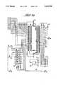
- FIGS. 4a, 4b and 4ctogether comprise a detailed electrical schematic diagram of the circuitry of the thermostat of the present invention
- FIG. 5is a block diagram of the adaptive loop control system showing the relationship between the control system and the room;
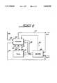
- FIG. 6is a block diagram of the adaptive controller
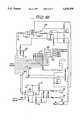
- FIG. 7is a detailed flow chart of the adaptive controller, and particularly illustrating the controller shown in FIG. 6;
- FIG. 8is a detailed flow chart of the adaptive control system and particularly illustrating the identifier shown in FIG. 6.
- the present inventionis directed to an electronic digital thermostat which is capable of use in a pneumatically controlled temperature control system of the type which has a pneumatic supply line which extends to various components of the control system and wherein the control elements of the system are controlled by varying the control pressure that is communicated to such elements.
- pressure within pneumatic control linesmay vary to adjust the position of dampers, control valves or the like which control the volume of steam, air and water to heating coils, radiators or the like, or in the case of dampers, controlling the amount of air that is forced into the space that is being controlled.
- Such systemsgenerally have been controlled by a pneumatic thermostat that is essentially mechanical in nature and wherein adjustment of the set point for the desired temperature has been performed by manual manipulation and except for the capability of providing day/night modes of operation, very little control is possible through the thermostat.
- the present inventionis intended to be operable with such a pneumatic control system and is capable of standalone operation or with an integrated supervisory and control system if desired. Because of its superior design, it is capable of being merely substituted for a prior pneumatic thermostat without any other alterations or modifications to the control elements or the heating apparatus.
- One of the particularly advantageous applications of the present inventionis for substitution for a pneumatic mechanical thermostat which controls a unit ventilator of the type which has been commonly used in school systems and the like.
- unit ventilatorsgenerally have a fan, a heating coil of which the heating element is steam, hot water or electrical.
- Such unit ventilatorsgenerally do not provide air conditioning in the true sense, but have outside dampers which are capable of admitting outside air which may often be cooler than air in the room.
- such unit ventilatorsare operable in a stand-alone mode and do not have system-wide capabilities which are extremely desirable in terms of efficient energy usage.
- thermostat of the present inventionincludes a processing means having internal memory and is therefore capable of running relatively complex control algorithms which are capable of providing proportional control, integral control, as well as derivative control, among other control schemes, such as a Smith predictor type of control scheme.
- the thermostatis manually adjustable so that its set point can be adjusted at the location of the thermostat to suit individual needs if desired, or it can be programmed so that it is not responsive to such individual controls during certain time periods or the like.
- a thermostat embodying the present inventionillustrated and includes an outer enclosure 12 having opposite end walls 14, opposite sidewalls 16 and a front wall 18.
- the sidewallspreferably have a plurality of openings 20 therein through which air may pass so that a temperature sensing device located within the enclosure will measure the temperature of ambient air in the area which the thermostat is intended to control.
- a display 22is shown in the front face 18 of the thermostat 10.
- the displayis preferably a liquid crystal display which will illustrate the current temperature, but may display other information, including the current time, the temperature set point of the thermostat, whether it is operating in one of the day or night control modes and the like.
- the thermostatpreferably has a pair of switches 24 and 26, which are illustrated to be up and down arrows and are provided to enable the temperature set point of the thermostat to be either increased or decreased upon pushing the appropriate pushbutton.
- the electronic componentsbe constructed using a printed circuit board such as is shown in FIG. 3.
- a processing means 28is provided, as is a temperature sensing device, preferably a pair of thermisters 30 and other electrical components, which are illustrated in FIG. 4, and which are mounted on a printed circuit board 32, but which are not shown in detail in FIG. 3.
- Connectors 33are provided for connection to the display 22 and switches 24 and 26, with the number illustrated in FIG. 3 not being the total number of such connectors but being diagrammatic of the intended construction. It should be understood that a ribbon or zebra connector 35 may be utilized or other appropriate conductors and connectors which are well known in the art and are not in and of themselves part of the present invention.
- the connectors 34are intended to connect the circuitry of the printed circuit board 32 with the electrical pneumatic components that are attached to a base 36 and additional connectors 38 are provided to provide connection to the local area network and to a source of power.
- the base 36has a number of openings, not shown, through which the power and LAN connectors may pass.
- the base platealso has internal ports to which pneumatic lines can be attached, and to this end, the pneumatic supply port 44 is shown connected to an electropneumatic valve 46 to which another pneumatic port 48 is attached and which comprises the controlled output.
- the port 48is also connected to a second valve 50 which in turn is connected to a bleed port 52.
- electropneumatic valves 46 and 50are shown to be generally cylindrical and may be in the form of conventional solenoid valves. However, it should be understood that any suitable control device may be used which is operable in response to appropriate electrical signals being applied thereto. It is conventional practice that the pneumatic pressure in the control port 48 is variable within the range of the supply pressure and atmospheric pressure, and the controlled pressure may be adjusted by operating one or the other of the control valves 46 and 50.
- the valvesoperate to selectively communicate air among the ports 44, 48 and 52 when they are open and isolate one from another when they are closed.
- the pressure in the controlled output port 48may be increased by opening the valve 46 which communicates the higher supply pressure to the controlled output port.
- the valve 50may be opened to bleed pressure to atmosphere via port 52.
- the output port 48may have a small molded manifold piece which is in communication with port 48 and which also includes a pneumatic transducer element, diagrammatically illustrated at 54, for providing an electrical signal to the circuitry of FIG. 4 which is indicative of the controlled pressure in port 48.
- the thermostat 10is adapted for use with apparatus such as a unit ventilator, the schematic diagram of which is shown in FIG. 2, and which has a fan 60 and a pneumatic electric switch 62, for turning the fan on when it is otherwise placed in condition for operation.
- the thermostat 10is shown with power lines 64 and LAN lines 66 which can be connected to a remote central control station 67.
- the thermostat 10has a pneumatic supply line 44' attached to port 44 and an output line 48' attached to port 48, which line 48' extends to a valve 68 that admits hot water, steam or the like to a heating coil 70.
- the pneumatic line 48'also extends to a pneumatically controlled damper control 72 and to another valve 74 which controls the flow of steam, hot water or the like to an auxiliary radiation coil 76.
- the circuitryis driven by the processing means 28, (FIG. 4a) which is preferably a model 68HC11 micro-controller manufactured by Motorola.
- the micro-controlleris driven by a clock circuit comprising a crystal 80 that is connected to pins 7 and 8. Pins 9-15 extend to the display 22, via a display driver integrated circuit of conventional design which is not shown.
- the valves 46 and 50are illustrated in FIG. 4a as being solenoid valves and the solenoid which increases the pressure 46 is driven by lines from pins 37 and 38, through a driver circuit 82, while lines from pins 35 and 36 operate the pressure reducing solenoid 50.
- the circuitryalso includes a power up/down reset circuit 84.
- Power lines 64are preferably 24 volt alternating current lines that are applied to a full wave rectifier, indicated generally at 86, (FIG. 4c) which is applied to a switching mode power supply circuit 88, preferably a Model MC34129 manufactured by Motorola. It supplies plus and minus 5 Volts D.C. (VDC) on lines 90 and 92, respectively, which are distributed to various portions of the circuitry as illustrated.
- VDCVolts D.C.
- lines 90 and 92are connected to an integrated circuit 94 (FIG. 4b) which provides a reference voltage of 11/2 VDC on line 96 and a 4.1 VDC reference voltage on line 98, both of which are respectively connected to pins 51 and 52 of the micro-controller 28 (FIG. 4a).
- the switches 24 and 26are connected to pins 49 and 47, respectively, for adjusting the set point of the thermostat and lines 100 are provided as spares for other functional input signals that may be desired.
- the temperature measuring functionis performed by the pair of thermistors 30 connected in parallel with one another which provide an electrical output to the micro-controller at pin 45 that is proportional to the temperature that is sensed. In this regard, two thermistors are used to provide an average value for use by the micro-controller 28.
- the pressure transducer 54has positive and negative outputs which are connected to an amplifier circuit, indicated generally at 102, which provides an amplified signal to pin 43 of the micro-controller.
- the thermostat 10compensates for unexpected changes in the controlled pressure due to unexpected line leaks, actuator leaks or other changes in control pressure.
- the thermostat 10uses line pressure feedback to maintain the line pressure at a selected level.
- the signal from the transducer 54serves as a feedback mechanism, representing the actual pressure in the pressure line which is monitored by the micro-controller.
- the controllerdetermines that no change in temperature, hence line pressure, is necessary but the controlled pressure decreases or increases, the micro-controller will open or close the control valves accordingly to maintain a constant control pressure.
- the sensed control pressure signalmay be compared to the desired pressure as determined by a PID loop, to determine the suitable change in pressure necessary to obtain the desired temperature.
- Communication with a LAN network via line 66is provided by circuitry associated with a RS485 transmission receiver integrated circuit 103 which has lines 104 that extend to pins 20 and 21 of the micro-controller and a select line 106 that extends to pin 42 thereof.
- the flow chart for the adaptive control algorithm that controls the operation of the thermostatis shown in FIG. 5 and has a room temperature set point applied by a control dial switch on the thermostat itself or is supplied by a remote control station via the LAN communication.
- the adaptive controlling algorithmcontinuously calculates robust controller gains required for accurate temperature control in a room. As the properties and characteristics of the room change, the algorithm adjusts the controller gains appropriately to maintain robust control.
- the algorithmadapts particularly well to gradual changes in room parameters. Sudden changes, such as a large rise or drop in the temperature of the water going to a heating or cooling coil, cause temporary fluctuations in room temperature, as they would with any controller, but the adaptive controller retunes itself and returns the room to good control.
- the algorithmis a single loop controller.
- One input, Y q (n), from the room temperature sensor 108is applied via line 110 to the controller 112 and it provides and output U(n) on line 114 to block 116, which represents the dynamics of the room and the actuator.
- the output X(t)represents the temperature rise or fall in the room due to the operation of the actuator.
- the room modelsymbolically has a summing junction 118 which receives the units of temperature X(t) and the load and the room temperature is represented by Y(t) on line 120 which is sensed by the sensor 108.
- the loadis defined as any temperature effect in the room which is not a direct result of the control efforts as applied through the actuator.
- the room temperature Y(t)is sampled by the sensor and quantized by no more than 0.25 degrees F, generating signal Y q (n).
- the adaptive controller 112itself consists of three primary blocks, which consist of a controller block 122, a tuner block 124 and an identifier block 126. These blocks define an algorithm for room temperature control.
- the controller 122uses the room temperature setpoint r(n) on line 128 and the actual room temperature Y(n) to create a control signal U(n). This signal drives an actuator in such a way as to keep the actual room temperature at the setpoint.
- the identifier 126uses the control signal from the controller and the actual room temperature signal to recursively calculate appropriate parameters for a second order room model, and outputs the parameters in the form of a vector Qaux, identified at 130, and a gain factor k on line 132.
- the tuner block 124uses the room model parameter estimates generated by the identifier and calculates appropriate controller gains, i.e., the proportional gain factor K p on line 134, the integral gain factor K i on line 136 and the derivative gain factor K d on line 138, for the controller 122 to use.
- the controller 122is illustrated and comprises a Smith Predictor structure with an imbedded PID controller.
- the estimated room modelis used in the structure, but it is divided into two parts. The first part contains the dynamic elements of the model and the second part contains only a time delay.
- the principle of the Smith Predictoris simple; if the estimated room model is exactly right, then the signal C(n) will be equal to the output of the room, Y(n). The signal (Y q (n)-C(n)) will then be equal to the load.
- the problem of controlling the room, with its time delayis then reduced to the problem of controlling the dynamic part of the estimated room model with no time delay.
- the Smith Predictorlimits if not eliminates the effects of a time delay.
- the structure of the controller 122is shown in FIG. 7 to have a PID controller 140, a room dynamic model 142 and a room delay model 144 interconnected as shown.
- the output U(n)is applied via line 114 to the room dynamic model 142 and the model block 142 provides an output A(n) on line 146 that is applied to the room delay model 144 and to a summing junction 148.
- the output of the room delay model 144is C(n) on line 150 and it is compared with the sensed room temperature Y q (n) on line 110 and the difference determined by summing junction 152 is applied to the summing junction 148 via line 154.
- the output of the summing junction 148appears on line 156 that is compared with temperature set point r(n) from line 128 at summing junction 158 to provide an error signal e(n) on line 158 that is applied to the PID controller 140 .
- the PID in the controlleris a standard digital PID.
- the P, I and D termsare calculated separately and added together and limited between given high and low limits to create the output U(n).
- the room modelincludes effects from the actuator, the temperature sensor, and the room itself.
- the dynamic part of the room modelrepresents the equation: ##EQU2## which can be rewritten into the following vector equation:
- the room delay modelsimply delays the signal A(n) by the time k*T s .
- the formulais:
- the tuner 124calculates PID gains for the controller using the Zeigler-Nichols tuning formulas. Instead of going through the painstaking and time-consuming process of raising the P-gain in successive trials in order to find the "ultimate gain" (K max ) and the associated period of oscillation (T o ), as the classic tuning procedure requires, the ultimate gain is calculated analytically, directly from the estimated room model parameters.
- the formulas for these calculationsare: ##EQU3## These values are then used in the Ziegler-Nichols formulas to produce robust PID gains: ##EQU4## In the event a proportional-integral controller is employed, the following formulas are then used to produce robust PI gains:
- the identifier shown in FIG. 8is comprised of six blocks: the two difference operators 160, 162, a time delay identifier 164, a functional coefficients identifier 166, a coefficients filter 168, and a stability supervisor 170.
- the difference operator blocks 160, 162simply subtract the previous value from the current value. These blocks are required because the two identifier blocks 164 and 166 require only the change in a value from sample time to sample time, not the actual value itself.
- the signals which pass through the difference operatorsare the output from the controller (U(n)), and the measured room temperature (Y q (n)). The equations used are:
- the coefficients identifierdetermines recursively the values of a set of model parameters which cause predicted model outputs to most closely match actual outputs (room temperature).
- the algorithm usedis the Recursive Instrumental Variables algorithm.
- the actual algorithm used, in vector/matrix formulation,is as follows: ##EQU5## where ⁇ is a forgetting factor.
- the coefficients filter 168filters each of the estimated model parameters held in vector Q.
- the filter 168is required to ensure that model estimates change very smoothly, which will allow the controller to control more smoothly.
- the filter 168 usedis as follows:
- ris the filter factor, initially set to 0.01 and j represents corresponding individual elements of the matrices.
- the coefficients stability supervisor 170checks the parameter estimates coming out of the coefficients identifier 166 to make sure that the estimated model is stable. It also checks that K max , coming from the tuner 124 is positive, and therefore stable.
- a stability testis performed according to the following criteria.
- the modelis unstable if any of the following occurs:
- the supervisordoes three things:
- the time delay identifier 164estimates the time delay by evaluating a cost function, J(kt), for different values of kt. The value of kt which results in the lowest J is selected as the estimated time delay, k.
- the cost functionis evaluated for all integers between the predefined k max and k min .
- the cost functionis:
- the cost functionsrun constantly, each evaluating using a different possible time delay, kt.
- the value for the time delay which is selected and used for parameter estimation and controlis the value which results in the lowest J.
- thermostathas many desirable attributes and advantages. It is particularly adapted to replace a conventional mechanical pneumatic thermostat and provide system-wide control as well as operate in a stand alone mode, because it is driven by a microcontroller having extensive memory, extremely complex control algorithms may be implemented and extreme flexibility in switching from various modes of operation are possible. Because of the extremely compact design, the thermostat is easily installed and is relatively inexpensive to manufacture, given the extraordinary flexibility and capability of operation.
Landscapes
- Engineering & Computer Science (AREA)
- Chemical & Material Sciences (AREA)
- Combustion & Propulsion (AREA)
- Mechanical Engineering (AREA)
- General Engineering & Computer Science (AREA)
- Physics & Mathematics (AREA)
- Signal Processing (AREA)
- Fuzzy Systems (AREA)
- Mathematical Physics (AREA)
- Human Computer Interaction (AREA)
- General Physics & Mathematics (AREA)
- Automation & Control Theory (AREA)
- Control Of Temperature (AREA)
Abstract
Description
A(n)=(-A(n-1)-A(n-2)U(n-1)U(n-2))*Q.sub.aux
C(n)=A(n-k)
K.sub.p =0.45*K.sub.max
K.sub.i =1.2*K.sub.p /T.sub.o
Ui(n)=U(n)-U(n-1)
Yi(n)=Y(n)-Y(n-1)
Q.sub.aux (n).sub.j =(1-r)*Q.sub.aux (n-1).sub.j +r*(Q(n).sub.j
1) 1+a.sub.1Q +a.sub.2Q >0
2) 1-a.sub.1Q +a.sub.2Q >0
3) |a.sub.2Q |<1
4) K.sub.max ≦0
J(kt,n)=β.sub.k *J(kt,n-1)+(Yi(n)-Yi(n,kt)).sup.2
Claims (39)
Priority Applications (1)
| Application Number | Priority Date | Filing Date | Title |
|---|---|---|---|
| US08/482,609US5634590A (en) | 1993-06-16 | 1995-06-07 | Direct digital control thermostat |
Applications Claiming Priority (3)
| Application Number | Priority Date | Filing Date | Title |
|---|---|---|---|
| US7860593A | 1993-06-16 | 1993-06-16 | |
| US27611994A | 1994-07-05 | 1994-07-05 | |
| US08/482,609US5634590A (en) | 1993-06-16 | 1995-06-07 | Direct digital control thermostat |
Related Parent Applications (1)
| Application Number | Title | Priority Date | Filing Date |
|---|---|---|---|
| US27611994AContinuation-In-Part | 1993-06-16 | 1994-07-05 |
Publications (1)
| Publication Number | Publication Date |
|---|---|
| US5634590Atrue US5634590A (en) | 1997-06-03 |
Family
ID=26760740
Family Applications (1)
| Application Number | Title | Priority Date | Filing Date |
|---|---|---|---|
| US08/482,609Expired - Fee RelatedUS5634590A (en) | 1993-06-16 | 1995-06-07 | Direct digital control thermostat |
Country Status (1)
| Country | Link |
|---|---|
| US (1) | US5634590A (en) |
Cited By (63)
| Publication number | Priority date | Publication date | Assignee | Title |
|---|---|---|---|---|
| US6169937B1 (en)* | 1998-04-14 | 2001-01-02 | Honeywell International Inc. | Subbase programmable control system |
| US6264111B1 (en)* | 1993-06-16 | 2001-07-24 | Siemens Building Technologies, Inc. | Proportional-integral-derivative controller having adaptive control capability |
| WO2002003160A1 (en)* | 2000-07-04 | 2002-01-10 | Mattson Thermal Products Gmbh | Method and device for thermally treating objects |
| US20020036601A1 (en)* | 1998-07-31 | 2002-03-28 | Resmed Limited | CPAP apparatus for switching between operational modes of the CPAP apparatus and a controller and method for doing the same |
| US6742716B1 (en) | 2003-02-28 | 2004-06-01 | Standard-Thomson Corporation | Thermostat |
| US6764020B1 (en) | 2003-02-28 | 2004-07-20 | Standard-Thomson Corporation | Thermostat apparatus for use with temperature control system |
| US20050067595A1 (en)* | 2003-08-01 | 2005-03-31 | Robert Teti | Municipal water delivery control systems |
| US7432477B2 (en) | 2005-04-19 | 2008-10-07 | Robert Teti | Set-back control for both HVAC and water heater via a single programmable thermostat |
| US20110166712A1 (en)* | 2010-03-18 | 2011-07-07 | Marcus Kramer | Deadband control of pneumatic control devices |
| USD648641S1 (en) | 2009-10-21 | 2011-11-15 | Lennox Industries Inc. | Thin cover plate for an electronic system controller |
| USD648642S1 (en) | 2009-10-21 | 2011-11-15 | Lennox Industries Inc. | Thin cover plate for an electronic system controller |
| US8239066B2 (en) | 2008-10-27 | 2012-08-07 | Lennox Industries Inc. | System and method of use for a user interface dashboard of a heating, ventilation and air conditioning network |
| US8255086B2 (en) | 2008-10-27 | 2012-08-28 | Lennox Industries Inc. | System recovery in a heating, ventilation and air conditioning network |
| US8260444B2 (en) | 2010-02-17 | 2012-09-04 | Lennox Industries Inc. | Auxiliary controller of a HVAC system |
| US8295981B2 (en) | 2008-10-27 | 2012-10-23 | Lennox Industries Inc. | Device commissioning in a heating, ventilation and air conditioning network |
| US8352081B2 (en) | 2008-10-27 | 2013-01-08 | Lennox Industries Inc. | Communication protocol system and method for a distributed-architecture heating, ventilation and air conditioning network |
| US8352080B2 (en) | 2008-10-27 | 2013-01-08 | Lennox Industries Inc. | Communication protocol system and method for a distributed-architecture heating, ventilation and air conditioning network |
| US20130075484A1 (en)* | 2010-01-19 | 2013-03-28 | Millennial Net, Inc. | Systems and methods utilizing a wireless mesh network |
| US8433446B2 (en) | 2008-10-27 | 2013-04-30 | Lennox Industries, Inc. | Alarm and diagnostics system and method for a distributed-architecture heating, ventilation and air conditioning network |
| US8437877B2 (en) | 2008-10-27 | 2013-05-07 | Lennox Industries Inc. | System recovery in a heating, ventilation and air conditioning network |
| US8437878B2 (en) | 2008-10-27 | 2013-05-07 | Lennox Industries Inc. | Alarm and diagnostics system and method for a distributed architecture heating, ventilation and air conditioning network |
| US8442693B2 (en) | 2008-10-27 | 2013-05-14 | Lennox Industries, Inc. | System and method of use for a user interface dashboard of a heating, ventilation and air conditioning network |
| US8452456B2 (en) | 2008-10-27 | 2013-05-28 | Lennox Industries Inc. | System and method of use for a user interface dashboard of a heating, ventilation and air conditioning network |
| US8452906B2 (en) | 2008-10-27 | 2013-05-28 | Lennox Industries, Inc. | Communication protocol system and method for a distributed-architecture heating, ventilation and air conditioning network |
| US8463443B2 (en) | 2008-10-27 | 2013-06-11 | Lennox Industries, Inc. | Memory recovery scheme and data structure in a heating, ventilation and air conditioning network |
| US8463442B2 (en) | 2008-10-27 | 2013-06-11 | Lennox Industries, Inc. | Alarm and diagnostics system and method for a distributed architecture heating, ventilation and air conditioning network |
| US20130147598A1 (en)* | 1991-12-23 | 2013-06-13 | Steven M. Hoffberg | Adaptive pattern recognition based controller apparatus and method and human-interface therefore |
| US8527099B2 (en)* | 2008-01-29 | 2013-09-03 | Cypress Envirosystems, Inc. | Pneumatic control device and system |
| US8525361B1 (en) | 2008-10-06 | 2013-09-03 | Cypress Envirosystems, Inc. | Pneumatic energy harvesting devices, methods and systems |
| US8543243B2 (en) | 2008-10-27 | 2013-09-24 | Lennox Industries, Inc. | System and method of use for a user interface dashboard of a heating, ventilation and air conditioning network |
| US8548630B2 (en) | 2008-10-27 | 2013-10-01 | Lennox Industries, Inc. | Alarm and diagnostics system and method for a distributed-architecture heating, ventilation and air conditioning network |
| US8560125B2 (en) | 2008-10-27 | 2013-10-15 | Lennox Industries | Communication protocol system and method for a distributed-architecture heating, ventilation and air conditioning network |
| US8564400B2 (en) | 2008-10-27 | 2013-10-22 | Lennox Industries, Inc. | Communication protocol system and method for a distributed-architecture heating, ventilation and air conditioning network |
| US8600559B2 (en) | 2008-10-27 | 2013-12-03 | Lennox Industries Inc. | Method of controlling equipment in a heating, ventilation and air conditioning network |
| US8600558B2 (en) | 2008-10-27 | 2013-12-03 | Lennox Industries Inc. | System recovery in a heating, ventilation and air conditioning network |
| US8615326B2 (en) | 2008-10-27 | 2013-12-24 | Lennox Industries Inc. | System and method of use for a user interface dashboard of a heating, ventilation and air conditioning network |
| US8655491B2 (en) | 2008-10-27 | 2014-02-18 | Lennox Industries Inc. | Alarm and diagnostics system and method for a distributed architecture heating, ventilation and air conditioning network |
| US8655490B2 (en) | 2008-10-27 | 2014-02-18 | Lennox Industries, Inc. | System and method of use for a user interface dashboard of a heating, ventilation and air conditioning network |
| US8661165B2 (en) | 2008-10-27 | 2014-02-25 | Lennox Industries, Inc. | Device abstraction system and method for a distributed architecture heating, ventilation and air conditioning system |
| US8694164B2 (en) | 2008-10-27 | 2014-04-08 | Lennox Industries, Inc. | Interactive user guidance interface for a heating, ventilation and air conditioning system |
| US8725298B2 (en) | 2008-10-27 | 2014-05-13 | Lennox Industries, Inc. | Alarm and diagnostics system and method for a distributed architecture heating, ventilation and conditioning network |
| US8744629B2 (en) | 2008-10-27 | 2014-06-03 | Lennox Industries Inc. | System and method of use for a user interface dashboard of a heating, ventilation and air conditioning network |
| US8762666B2 (en) | 2008-10-27 | 2014-06-24 | Lennox Industries, Inc. | Backup and restoration of operation control data in a heating, ventilation and air conditioning network |
| US8774210B2 (en) | 2008-10-27 | 2014-07-08 | Lennox Industries, Inc. | Communication protocol system and method for a distributed-architecture heating, ventilation and air conditioning network |
| US8788100B2 (en) | 2008-10-27 | 2014-07-22 | Lennox Industries Inc. | System and method for zoning a distributed-architecture heating, ventilation and air conditioning network |
| US8798796B2 (en) | 2008-10-27 | 2014-08-05 | Lennox Industries Inc. | General control techniques in a heating, ventilation and air conditioning network |
| US8802981B2 (en) | 2008-10-27 | 2014-08-12 | Lennox Industries Inc. | Flush wall mount thermostat and in-set mounting plate for a heating, ventilation and air conditioning system |
| US8855825B2 (en) | 2008-10-27 | 2014-10-07 | Lennox Industries Inc. | Device abstraction system and method for a distributed-architecture heating, ventilation and air conditioning system |
| US8874815B2 (en) | 2008-10-27 | 2014-10-28 | Lennox Industries, Inc. | Communication protocol system and method for a distributed architecture heating, ventilation and air conditioning network |
| US8892797B2 (en) | 2008-10-27 | 2014-11-18 | Lennox Industries Inc. | Communication protocol system and method for a distributed-architecture heating, ventilation and air conditioning network |
| US8977794B2 (en) | 2008-10-27 | 2015-03-10 | Lennox Industries, Inc. | Communication protocol system and method for a distributed-architecture heating, ventilation and air conditioning network |
| US8994539B2 (en) | 2008-10-27 | 2015-03-31 | Lennox Industries, Inc. | Alarm and diagnostics system and method for a distributed-architecture heating, ventilation and air conditioning network |
| US9152155B2 (en) | 2008-10-27 | 2015-10-06 | Lennox Industries Inc. | Device abstraction system and method for a distributed-architecture heating, ventilation and air conditioning system |
| US9261888B2 (en) | 2008-10-27 | 2016-02-16 | Lennox Industries Inc. | System and method of use for a user interface dashboard of a heating, ventilation and air conditioning network |
| US9268345B2 (en) | 2008-10-27 | 2016-02-23 | Lennox Industries Inc. | System and method of use for a user interface dashboard of a heating, ventilation and air conditioning network |
| US9325517B2 (en) | 2008-10-27 | 2016-04-26 | Lennox Industries Inc. | Device abstraction system and method for a distributed-architecture heating, ventilation and air conditioning system |
| US9377768B2 (en) | 2008-10-27 | 2016-06-28 | Lennox Industries Inc. | Memory recovery scheme and data structure in a heating, ventilation and air conditioning network |
| US9432208B2 (en) | 2008-10-27 | 2016-08-30 | Lennox Industries Inc. | Device abstraction system and method for a distributed architecture heating, ventilation and air conditioning system |
| CN106574797A (en)* | 2014-09-01 | 2017-04-19 | 三菱电机株式会社 | Air conditioning system control device and air conditioning system control method |
| US9632490B2 (en) | 2008-10-27 | 2017-04-25 | Lennox Industries Inc. | System and method for zoning a distributed architecture heating, ventilation and air conditioning network |
| US9651925B2 (en) | 2008-10-27 | 2017-05-16 | Lennox Industries Inc. | System and method for zoning a distributed-architecture heating, ventilation and air conditioning network |
| US20170138629A1 (en)* | 2010-11-19 | 2017-05-18 | Google Inc. | Electronic device controller with user-friendly installation features facilitating both do-it-yourself and professional installation scenarios |
| US9678486B2 (en) | 2008-10-27 | 2017-06-13 | Lennox Industries Inc. | Device abstraction system and method for a distributed-architecture heating, ventilation and air conditioning system |
Citations (18)
| Publication number | Priority date | Publication date | Assignee | Title |
|---|---|---|---|---|
| CA687977A (en)* | 1964-06-02 | T. Jones Hershul | Control for an electro-pneumatic system | |
| US3882881A (en)* | 1973-01-12 | 1975-05-13 | American Chain & Cable Co | Pneumatic transmitter of electrical phenomena |
| US4172555A (en)* | 1978-05-22 | 1979-10-30 | Levine Michael R | Adaptive electronic thermostat |
| US4298946A (en)* | 1978-12-18 | 1981-11-03 | Texas Instruments Incorporated | Electronically controlled programmable digital thermostat |
| US4388692A (en)* | 1980-09-03 | 1983-06-14 | Texas Instruments Incorporated | Electronically controlled programmable digital thermostat having variable threshold hysteresis with time |
| US4410132A (en)* | 1980-11-14 | 1983-10-18 | Levine Michael R | Thermostat with dead zone seeking servo action |
| US4442972A (en)* | 1981-09-14 | 1984-04-17 | Texas Instruments Incorporated | Electrically controlled programmable digital thermostat and method for regulating the operation of multistage heating and cooling systems |
| US4639876A (en)* | 1984-10-22 | 1987-01-27 | Deeds Robert G | Multi-unit energy use monitor |
| US4646964A (en)* | 1982-03-26 | 1987-03-03 | Parker Electronics, Inc. | Temperature control system |
| US4688547A (en)* | 1986-07-25 | 1987-08-25 | Carrier Corporation | Method for providing variable output gas-fired furnace with a constant temperature rise and efficiency |
| US4702305A (en)* | 1987-03-30 | 1987-10-27 | Honeywell Inc. | Temperature control system for control of a multiplant environmental unit |
| US4799176A (en)* | 1986-12-29 | 1989-01-17 | Harper-Wyman Company | Electronic digital thermostat |
| US4829458A (en)* | 1987-07-07 | 1989-05-09 | Honeywell Incorporated | External constant specification in a digital electronic system |
| US4897798A (en)* | 1986-12-08 | 1990-01-30 | American Telephone And Telegraph Company | Adaptive environment control system |
| US4942613A (en)* | 1988-12-02 | 1990-07-17 | Heil-Quaker Corporation | Service thermostat |
| US4991770A (en)* | 1990-03-27 | 1991-02-12 | Honeywell Inc. | Thermostat with means for disabling PID control |
| US5114070A (en)* | 1990-11-06 | 1992-05-19 | American Standard Inc. | Pneumatic direct digital controller |
| US5323961A (en)* | 1991-06-11 | 1994-06-28 | Landis & Gyr Powers, Inc. | Apparatus for controlling unit ventilators |
- 1995
- 1995-06-07USUS08/482,609patent/US5634590A/ennot_activeExpired - Fee Related
Patent Citations (18)
| Publication number | Priority date | Publication date | Assignee | Title |
|---|---|---|---|---|
| CA687977A (en)* | 1964-06-02 | T. Jones Hershul | Control for an electro-pneumatic system | |
| US3882881A (en)* | 1973-01-12 | 1975-05-13 | American Chain & Cable Co | Pneumatic transmitter of electrical phenomena |
| US4172555A (en)* | 1978-05-22 | 1979-10-30 | Levine Michael R | Adaptive electronic thermostat |
| US4298946A (en)* | 1978-12-18 | 1981-11-03 | Texas Instruments Incorporated | Electronically controlled programmable digital thermostat |
| US4388692A (en)* | 1980-09-03 | 1983-06-14 | Texas Instruments Incorporated | Electronically controlled programmable digital thermostat having variable threshold hysteresis with time |
| US4410132A (en)* | 1980-11-14 | 1983-10-18 | Levine Michael R | Thermostat with dead zone seeking servo action |
| US4442972A (en)* | 1981-09-14 | 1984-04-17 | Texas Instruments Incorporated | Electrically controlled programmable digital thermostat and method for regulating the operation of multistage heating and cooling systems |
| US4646964A (en)* | 1982-03-26 | 1987-03-03 | Parker Electronics, Inc. | Temperature control system |
| US4639876A (en)* | 1984-10-22 | 1987-01-27 | Deeds Robert G | Multi-unit energy use monitor |
| US4688547A (en)* | 1986-07-25 | 1987-08-25 | Carrier Corporation | Method for providing variable output gas-fired furnace with a constant temperature rise and efficiency |
| US4897798A (en)* | 1986-12-08 | 1990-01-30 | American Telephone And Telegraph Company | Adaptive environment control system |
| US4799176A (en)* | 1986-12-29 | 1989-01-17 | Harper-Wyman Company | Electronic digital thermostat |
| US4702305A (en)* | 1987-03-30 | 1987-10-27 | Honeywell Inc. | Temperature control system for control of a multiplant environmental unit |
| US4829458A (en)* | 1987-07-07 | 1989-05-09 | Honeywell Incorporated | External constant specification in a digital electronic system |
| US4942613A (en)* | 1988-12-02 | 1990-07-17 | Heil-Quaker Corporation | Service thermostat |
| US4991770A (en)* | 1990-03-27 | 1991-02-12 | Honeywell Inc. | Thermostat with means for disabling PID control |
| US5114070A (en)* | 1990-11-06 | 1992-05-19 | American Standard Inc. | Pneumatic direct digital controller |
| US5323961A (en)* | 1991-06-11 | 1994-06-28 | Landis & Gyr Powers, Inc. | Apparatus for controlling unit ventilators |
Non-Patent Citations (6)
| Title |
|---|
| Advertising brochure, "Advanced Concepts for VAV Control", Alerton Technologies, Inc., date unknown. |
| Advertising brochure, Advanced Concepts for VAV Control , Alerton Technologies, Inc., date unknown.* |
| Preliminary Product Description, "SOLOView" American Auto-Matrix, Inc., Oct. 29, 1992, pp. 1-3. |
| Preliminary Product Description, SOLOView American Auto Matrix, Inc., Oct. 29, 1992, pp. 1 3.* |
| Technical Instruction brochure, "TH 192 S Single Temperature Room Thermostat", Landis & Gyr Powers, Inc., Jan. 1990. |
| Technical Instruction brochure, TH 192 S Single Temperature Room Thermostat , Landis & Gyr Powers, Inc., Jan. 1990.* |
Cited By (77)
| Publication number | Priority date | Publication date | Assignee | Title |
|---|---|---|---|---|
| US8892495B2 (en)* | 1991-12-23 | 2014-11-18 | Blanding Hovenweep, Llc | Adaptive pattern recognition based controller apparatus and method and human-interface therefore |
| US20130147598A1 (en)* | 1991-12-23 | 2013-06-13 | Steven M. Hoffberg | Adaptive pattern recognition based controller apparatus and method and human-interface therefore |
| US6264111B1 (en)* | 1993-06-16 | 2001-07-24 | Siemens Building Technologies, Inc. | Proportional-integral-derivative controller having adaptive control capability |
| US6169937B1 (en)* | 1998-04-14 | 2001-01-02 | Honeywell International Inc. | Subbase programmable control system |
| US20020036601A1 (en)* | 1998-07-31 | 2002-03-28 | Resmed Limited | CPAP apparatus for switching between operational modes of the CPAP apparatus and a controller and method for doing the same |
| US6775471B2 (en) | 2000-07-04 | 2004-08-10 | Mattson Thermal Products Gmbh | Method and device for thermally treating objects |
| WO2002003160A1 (en)* | 2000-07-04 | 2002-01-10 | Mattson Thermal Products Gmbh | Method and device for thermally treating objects |
| US6764020B1 (en) | 2003-02-28 | 2004-07-20 | Standard-Thomson Corporation | Thermostat apparatus for use with temperature control system |
| US6742716B1 (en) | 2003-02-28 | 2004-06-01 | Standard-Thomson Corporation | Thermostat |
| US20050067595A1 (en)* | 2003-08-01 | 2005-03-31 | Robert Teti | Municipal water delivery control systems |
| US20060202143A1 (en)* | 2003-08-01 | 2006-09-14 | Robert Teti | Municipal delivery control systems |
| US7111817B2 (en) | 2003-08-01 | 2006-09-26 | Robert Teti | Municipal water delivery control systems |
| US7432477B2 (en) | 2005-04-19 | 2008-10-07 | Robert Teti | Set-back control for both HVAC and water heater via a single programmable thermostat |
| US20080314337A1 (en)* | 2005-04-19 | 2008-12-25 | Robert Teti | Water heater control |
| US8527099B2 (en)* | 2008-01-29 | 2013-09-03 | Cypress Envirosystems, Inc. | Pneumatic control device and system |
| US8525361B1 (en) | 2008-10-06 | 2013-09-03 | Cypress Envirosystems, Inc. | Pneumatic energy harvesting devices, methods and systems |
| US8615326B2 (en) | 2008-10-27 | 2013-12-24 | Lennox Industries Inc. | System and method of use for a user interface dashboard of a heating, ventilation and air conditioning network |
| US8774210B2 (en) | 2008-10-27 | 2014-07-08 | Lennox Industries, Inc. | Communication protocol system and method for a distributed-architecture heating, ventilation and air conditioning network |
| US8352081B2 (en) | 2008-10-27 | 2013-01-08 | Lennox Industries Inc. | Communication protocol system and method for a distributed-architecture heating, ventilation and air conditioning network |
| US8352080B2 (en) | 2008-10-27 | 2013-01-08 | Lennox Industries Inc. | Communication protocol system and method for a distributed-architecture heating, ventilation and air conditioning network |
| US9678486B2 (en) | 2008-10-27 | 2017-06-13 | Lennox Industries Inc. | Device abstraction system and method for a distributed-architecture heating, ventilation and air conditioning system |
| US8433446B2 (en) | 2008-10-27 | 2013-04-30 | Lennox Industries, Inc. | Alarm and diagnostics system and method for a distributed-architecture heating, ventilation and air conditioning network |
| US8437877B2 (en) | 2008-10-27 | 2013-05-07 | Lennox Industries Inc. | System recovery in a heating, ventilation and air conditioning network |
| US8437878B2 (en) | 2008-10-27 | 2013-05-07 | Lennox Industries Inc. | Alarm and diagnostics system and method for a distributed architecture heating, ventilation and air conditioning network |
| US8442693B2 (en) | 2008-10-27 | 2013-05-14 | Lennox Industries, Inc. | System and method of use for a user interface dashboard of a heating, ventilation and air conditioning network |
| US8452456B2 (en) | 2008-10-27 | 2013-05-28 | Lennox Industries Inc. | System and method of use for a user interface dashboard of a heating, ventilation and air conditioning network |
| US8452906B2 (en) | 2008-10-27 | 2013-05-28 | Lennox Industries, Inc. | Communication protocol system and method for a distributed-architecture heating, ventilation and air conditioning network |
| US8463443B2 (en) | 2008-10-27 | 2013-06-11 | Lennox Industries, Inc. | Memory recovery scheme and data structure in a heating, ventilation and air conditioning network |
| US8463442B2 (en) | 2008-10-27 | 2013-06-11 | Lennox Industries, Inc. | Alarm and diagnostics system and method for a distributed architecture heating, ventilation and air conditioning network |
| US9651925B2 (en) | 2008-10-27 | 2017-05-16 | Lennox Industries Inc. | System and method for zoning a distributed-architecture heating, ventilation and air conditioning network |
| US9632490B2 (en) | 2008-10-27 | 2017-04-25 | Lennox Industries Inc. | System and method for zoning a distributed architecture heating, ventilation and air conditioning network |
| US8255086B2 (en) | 2008-10-27 | 2012-08-28 | Lennox Industries Inc. | System recovery in a heating, ventilation and air conditioning network |
| US8543243B2 (en) | 2008-10-27 | 2013-09-24 | Lennox Industries, Inc. | System and method of use for a user interface dashboard of a heating, ventilation and air conditioning network |
| US8548630B2 (en) | 2008-10-27 | 2013-10-01 | Lennox Industries, Inc. | Alarm and diagnostics system and method for a distributed-architecture heating, ventilation and air conditioning network |
| US8560125B2 (en) | 2008-10-27 | 2013-10-15 | Lennox Industries | Communication protocol system and method for a distributed-architecture heating, ventilation and air conditioning network |
| US8564400B2 (en) | 2008-10-27 | 2013-10-22 | Lennox Industries, Inc. | Communication protocol system and method for a distributed-architecture heating, ventilation and air conditioning network |
| US8600559B2 (en) | 2008-10-27 | 2013-12-03 | Lennox Industries Inc. | Method of controlling equipment in a heating, ventilation and air conditioning network |
| US8600558B2 (en) | 2008-10-27 | 2013-12-03 | Lennox Industries Inc. | System recovery in a heating, ventilation and air conditioning network |
| US9432208B2 (en) | 2008-10-27 | 2016-08-30 | Lennox Industries Inc. | Device abstraction system and method for a distributed architecture heating, ventilation and air conditioning system |
| US8655491B2 (en) | 2008-10-27 | 2014-02-18 | Lennox Industries Inc. | Alarm and diagnostics system and method for a distributed architecture heating, ventilation and air conditioning network |
| US8655490B2 (en) | 2008-10-27 | 2014-02-18 | Lennox Industries, Inc. | System and method of use for a user interface dashboard of a heating, ventilation and air conditioning network |
| US8661165B2 (en) | 2008-10-27 | 2014-02-25 | Lennox Industries, Inc. | Device abstraction system and method for a distributed architecture heating, ventilation and air conditioning system |
| US8694164B2 (en) | 2008-10-27 | 2014-04-08 | Lennox Industries, Inc. | Interactive user guidance interface for a heating, ventilation and air conditioning system |
| US8725298B2 (en) | 2008-10-27 | 2014-05-13 | Lennox Industries, Inc. | Alarm and diagnostics system and method for a distributed architecture heating, ventilation and conditioning network |
| US8744629B2 (en) | 2008-10-27 | 2014-06-03 | Lennox Industries Inc. | System and method of use for a user interface dashboard of a heating, ventilation and air conditioning network |
| US8761945B2 (en) | 2008-10-27 | 2014-06-24 | Lennox Industries Inc. | Device commissioning in a heating, ventilation and air conditioning network |
| US8762666B2 (en) | 2008-10-27 | 2014-06-24 | Lennox Industries, Inc. | Backup and restoration of operation control data in a heating, ventilation and air conditioning network |
| US8295981B2 (en) | 2008-10-27 | 2012-10-23 | Lennox Industries Inc. | Device commissioning in a heating, ventilation and air conditioning network |
| US9377768B2 (en) | 2008-10-27 | 2016-06-28 | Lennox Industries Inc. | Memory recovery scheme and data structure in a heating, ventilation and air conditioning network |
| US8788100B2 (en) | 2008-10-27 | 2014-07-22 | Lennox Industries Inc. | System and method for zoning a distributed-architecture heating, ventilation and air conditioning network |
| US8798796B2 (en) | 2008-10-27 | 2014-08-05 | Lennox Industries Inc. | General control techniques in a heating, ventilation and air conditioning network |
| US8802981B2 (en) | 2008-10-27 | 2014-08-12 | Lennox Industries Inc. | Flush wall mount thermostat and in-set mounting plate for a heating, ventilation and air conditioning system |
| US8855825B2 (en) | 2008-10-27 | 2014-10-07 | Lennox Industries Inc. | Device abstraction system and method for a distributed-architecture heating, ventilation and air conditioning system |
| US8874815B2 (en) | 2008-10-27 | 2014-10-28 | Lennox Industries, Inc. | Communication protocol system and method for a distributed architecture heating, ventilation and air conditioning network |
| US8892797B2 (en) | 2008-10-27 | 2014-11-18 | Lennox Industries Inc. | Communication protocol system and method for a distributed-architecture heating, ventilation and air conditioning network |
| US8239066B2 (en) | 2008-10-27 | 2012-08-07 | Lennox Industries Inc. | System and method of use for a user interface dashboard of a heating, ventilation and air conditioning network |
| US8977794B2 (en) | 2008-10-27 | 2015-03-10 | Lennox Industries, Inc. | Communication protocol system and method for a distributed-architecture heating, ventilation and air conditioning network |
| US8994539B2 (en) | 2008-10-27 | 2015-03-31 | Lennox Industries, Inc. | Alarm and diagnostics system and method for a distributed-architecture heating, ventilation and air conditioning network |
| US9152155B2 (en) | 2008-10-27 | 2015-10-06 | Lennox Industries Inc. | Device abstraction system and method for a distributed-architecture heating, ventilation and air conditioning system |
| US9261888B2 (en) | 2008-10-27 | 2016-02-16 | Lennox Industries Inc. | System and method of use for a user interface dashboard of a heating, ventilation and air conditioning network |
| US9268345B2 (en) | 2008-10-27 | 2016-02-23 | Lennox Industries Inc. | System and method of use for a user interface dashboard of a heating, ventilation and air conditioning network |
| US9325517B2 (en) | 2008-10-27 | 2016-04-26 | Lennox Industries Inc. | Device abstraction system and method for a distributed-architecture heating, ventilation and air conditioning system |
| USD648642S1 (en) | 2009-10-21 | 2011-11-15 | Lennox Industries Inc. | Thin cover plate for an electronic system controller |
| USD648641S1 (en) | 2009-10-21 | 2011-11-15 | Lennox Industries Inc. | Thin cover plate for an electronic system controller |
| US20130075484A1 (en)* | 2010-01-19 | 2013-03-28 | Millennial Net, Inc. | Systems and methods utilizing a wireless mesh network |
| US9785155B2 (en)* | 2010-01-19 | 2017-10-10 | Millennial Net, Inc. | Systems and methods utilizing a wireless mesh network |
| US9599359B2 (en) | 2010-02-17 | 2017-03-21 | Lennox Industries Inc. | Integrated controller an HVAC system |
| US9574784B2 (en) | 2010-02-17 | 2017-02-21 | Lennox Industries Inc. | Method of starting a HVAC system having an auxiliary controller |
| US8260444B2 (en) | 2010-02-17 | 2012-09-04 | Lennox Industries Inc. | Auxiliary controller of a HVAC system |
| US8788104B2 (en) | 2010-02-17 | 2014-07-22 | Lennox Industries Inc. | Heating, ventilating and air conditioning (HVAC) system with an auxiliary controller |
| US20110166712A1 (en)* | 2010-03-18 | 2011-07-07 | Marcus Kramer | Deadband control of pneumatic control devices |
| US20170138629A1 (en)* | 2010-11-19 | 2017-05-18 | Google Inc. | Electronic device controller with user-friendly installation features facilitating both do-it-yourself and professional installation scenarios |
| US9995499B2 (en)* | 2010-11-19 | 2018-06-12 | Google Llc | Electronic device controller with user-friendly installation features |
| CN106574797A (en)* | 2014-09-01 | 2017-04-19 | 三菱电机株式会社 | Air conditioning system control device and air conditioning system control method |
| EP3190348A4 (en)* | 2014-09-01 | 2018-05-02 | Mitsubishi Electric Corporation | Air conditioning system control device and air conditioning system control method |
| CN106574797B (en)* | 2014-09-01 | 2019-08-06 | 三菱电机株式会社 | Control device of air conditioning system and control method of air conditioning system |
| US10533763B2 (en) | 2014-09-01 | 2020-01-14 | Mitsubishi Electric Corporation | Controller of air-conditioning system and method for controlling air-conditioning system |
Similar Documents
| Publication | Publication Date | Title |
|---|---|---|
| US5634590A (en) | Direct digital control thermostat | |
| US6264111B1 (en) | Proportional-integral-derivative controller having adaptive control capability | |
| US7966104B2 (en) | Apparatus and method for the control of the indoor thermal environment having feed forward and feedback control using adaptive reference models | |
| US5691896A (en) | Field based process control system with auto-tuning | |
| US5769314A (en) | Variable air volume HVAC system controller and method | |
| US5613514A (en) | Pressure/vacuum regulator | |
| US7669777B2 (en) | Slope predictive control and digital PID control for a variable temperature control system | |
| US5682329A (en) | On-line monitoring of controllers in an environment control network | |
| US4089462A (en) | Temperature control system including K-Factor adjustment | |
| US7024254B2 (en) | Method for controlling a discrete system | |
| US5209398A (en) | Model-based thermobalance with feedback | |
| US10724758B2 (en) | Heat index thermostat | |
| JPH11126101A (en) | Improved adaptive flow rate control unit for flow rate controller | |
| WO2003033962A1 (en) | Method for controlling hvac units | |
| EP1000389B1 (en) | Adaptive cascade control algorithm | |
| CA2125014C (en) | Direct digital control thermostat | |
| US20030153986A1 (en) | Filtered variable control method for activating an electrical device | |
| US5557555A (en) | Circuit for regulating the air conditioning of premises | |
| EP0518131B1 (en) | Apparatus for controlling unit ventilators | |
| CA2125015C (en) | Proportional-integral-derivative controller having adaptive control capability | |
| JP2884705B2 (en) | Air conditioner | |
| JPS61239310A (en) | Temperature controller | |
| JP3259118B2 (en) | controller | |
| JPH0420736A (en) | air conditioner |
Legal Events
| Date | Code | Title | Description |
|---|---|---|---|
| AS | Assignment | Owner name:LANDIS & GYR POWERS, INC., ILLINOIS Free format text:ASSIGNMENT OF ASSIGNORS INTEREST;ASSIGNORS:GORSKI, WILLIAM H.;LAUER, WAYNE S.;IKENN, AMY L.;REEL/FRAME:007608/0477;SIGNING DATES FROM 19950802 TO 19950808 | |
| AS | Assignment | Owner name:LANDIS & GYR, INC., ILLINOIS Free format text:MERGER;ASSIGNORS:LANDIS & GYR POWERS, INC.;LANDIS & GYR, INC.;REEL/FRAME:008425/0696 Effective date:19960130 Owner name:LANDIS & STAEFA, INC., ILLINOIS Free format text:MERGER;ASSIGNORS:LANDIS & GYR POWERS, INC.;LANDIS & GYR, INC.;REEL/FRAME:008425/0696 Effective date:19960130 | |
| AS | Assignment | Owner name:LANDIS & GYR HOLDINGS, INC., ILLINOIS Free format text:MERGER;ASSIGNOR:LANDIS & STAEFA, INC.;REEL/FRAME:009638/0164 Effective date:19980930 Owner name:SIEMENS BUILDING TECHNOLOGIES, INC., ILLINOIS Free format text:MERGER & NAME CHANGE;ASSIGNORS:LANDIS & GYR HOLDINGS;CERBERUS HOLDINGS, INC.;REEL/FRAME:009638/0167 Effective date:19981001 | |
| FPAY | Fee payment | Year of fee payment:4 | |
| REMI | Maintenance fee reminder mailed | ||
| LAPS | Lapse for failure to pay maintenance fees | ||
| STCH | Information on status: patent discontinuation | Free format text:PATENT EXPIRED DUE TO NONPAYMENT OF MAINTENANCE FEES UNDER 37 CFR 1.362 | |
| FP | Lapsed due to failure to pay maintenance fee | Effective date:20050603 |