US5634327A - Method of operating a gas-turbine group - Google Patents
Method of operating a gas-turbine groupDownload PDFInfo
- Publication number
- US5634327A US5634327AUS08/552,958US55295895AUS5634327AUS 5634327 AUS5634327 AUS 5634327AUS 55295895 AUS55295895 AUS 55295895AUS 5634327 AUS5634327 AUS 5634327A
- Authority
- US
- United States
- Prior art keywords
- turbine
- combustion chamber
- load
- inlet temperature
- temperature
- Prior art date
- Legal status (The legal status is an assumption and is not a legal conclusion. Google has not performed a legal analysis and makes no representation as to the accuracy of the status listed.)
- Expired - Lifetime
Links
Images
Classifications
- F—MECHANICAL ENGINEERING; LIGHTING; HEATING; WEAPONS; BLASTING
- F02—COMBUSTION ENGINES; HOT-GAS OR COMBUSTION-PRODUCT ENGINE PLANTS
- F02C—GAS-TURBINE PLANTS; AIR INTAKES FOR JET-PROPULSION PLANTS; CONTROLLING FUEL SUPPLY IN AIR-BREATHING JET-PROPULSION PLANTS
- F02C9/00—Controlling gas-turbine plants; Controlling fuel supply in air- breathing jet-propulsion plants
- F02C9/16—Control of working fluid flow
- F02C9/20—Control of working fluid flow by throttling; by adjusting vanes
- F—MECHANICAL ENGINEERING; LIGHTING; HEATING; WEAPONS; BLASTING
- F02—COMBUSTION ENGINES; HOT-GAS OR COMBUSTION-PRODUCT ENGINE PLANTS
- F02C—GAS-TURBINE PLANTS; AIR INTAKES FOR JET-PROPULSION PLANTS; CONTROLLING FUEL SUPPLY IN AIR-BREATHING JET-PROPULSION PLANTS
- F02C6/00—Plural gas-turbine plants; Combinations of gas-turbine plants with other apparatus; Adaptations of gas-turbine plants for special use
- F02C6/003—Gas-turbine plants with heaters between turbine stages
- F—MECHANICAL ENGINEERING; LIGHTING; HEATING; WEAPONS; BLASTING
- F02—COMBUSTION ENGINES; HOT-GAS OR COMBUSTION-PRODUCT ENGINE PLANTS
- F02C—GAS-TURBINE PLANTS; AIR INTAKES FOR JET-PROPULSION PLANTS; CONTROLLING FUEL SUPPLY IN AIR-BREATHING JET-PROPULSION PLANTS
- F02C9/00—Controlling gas-turbine plants; Controlling fuel supply in air- breathing jet-propulsion plants
- F02C9/26—Control of fuel supply
- F02C9/28—Regulating systems responsive to plant or ambient parameters, e.g. temperature, pressure, rotor speed
Definitions
- the present inventionrelates to a method for regulating a gas turbine apparatus in part load operation.
- one object of the invention as defined in the claimsin a method of the type mentioned at the beginning, is to provide a novel regulating method which, by a simple regulating concept, permits reliable lowering of the load at maximized efficiency and minimized pollutant emissions, in particular as far as the NOx and CO emissions are concerned, while allowing for the fact that the gas-turbine group has sequential combustion.
- the essential advantage of the inventioncan be seen in the fact that the entire lowering of the load takes place at maximized partial-load efficiency, in which case, upon initiation of the lowering of the load, action is taken at the outset on the inlet temperature at the two turbines in such a way that a safety margin is thereby created in order to be able to withstand undamaged overshooting of the temperatures caused by regulating influences.
- the adjustment of the compressor guide bladesis in operative connection with the fuel regulation during the lowering of the load, this fuel regulation in turn being dependent upon the decreasing mass flow from the adjustment of the compressor guide blades.
- the loadis reduced by a few percent, in accordance with a lowering of the temperature by 20° C.
- This first actioninvolves creating a safety margin relative to the 100% load so that any following fuel regulating or other actions do not cause overshooting of the temperatures.
- This settingis established on account of the maximum temperature, taken as a basis, of the exhaust gases from the second turbine, which according to specification is 620°-640° C.
- the compressor guide bladesare then closed successively until below 50% of the rated load, the temperature at the inlet to the first turbine being held during this regulation at the reduced level relative to the temperature at rated load.
- the inlet temperature at the second turbinedecreases continuously, it being ensured that the temperature at the outlet of this second turbine does not exceed the aforesaid specification. So that the new regulation state can arise from the preceding actions, the fuel quantities to the individual combustion chambers must be suitably reduced, since the mass flow continually decreases due to the adjustment of the compressor guide blades. After the adjustment of the compressor guide blades is complete, the inlet temperature at the first turbine is kept constant for a while at the predetermined level, while the inlet temperature at the second turbine is continuously reduced. As soon as the remaining load of the second turbine has decreased by about half, the inlet temperature at the first turbine is likewise continuously reduced by appropriate lowering of the fuel quantity.
- a temperature measurementcan be provided at the outlet of the first turbine, which temperature measurement provides information in order to influence the fuel quantity for the second combustion chamber if need be.
- the loadcan be lowered further at high efficiency by preheating the intake air to the compressor by means of bled steam from the said steam circuit after final adjustment of the compressor guide blades.
- FIG. 1shows a gas-turbine group having sequential combustion
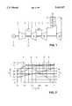
- FIG. 2shows a regulating method for lowering the load.
- FIG. 1a gas-turbine group having sequential combustion is shown.
- This gas-turbine groupconsists of a compressor 1, or a compressor unit equipped with intermediate cooling, in which the compression of the intake air 2 takes place.
- HP turbinehigh-pressure turbine
- This partial expansionis defined in that the exhaust gases 7 from the HP turbine 6 still have a relatively high temperature, of the order of magnitude of around 950° C. and above, and accordingly the blading of this HP turbine 6 consists of few moving-blade rows, preferably 1 to 3 stages.
- This LP combustion chamber 8preferably has the form of an annular throughflow duct into which a fuel is injected which, in connection with the predetermined temperature, forms the preconditions for self-ignition.
- a fuelis injected which, in connection with the predetermined temperature, forms the preconditions for self-ignition.
- this LP combustion chamber 8has vortex generators (not shown) which are preferably arranged upstream of the injection of the fuel and which form a backflow zone in the region of the flame front to guarantee reliable operation.
- the exhaust gases 7are thus processed again in the LP combustion chamber 8 to form hot gases 9, the temperature of which approximately corresponds to that of the HP combustion chamber 4.
- the temperatures of the hot gases 5, 9have no direct limit caused by the combustion chamber; on the contrary, this limit is predetermined first of all by the respective turbine to be acted upon and by the corresponding machine elements.
- the residual calorific potential of the burnt gases 11can be used, for example, for the steam generation of a downstream steam circuit (not shown).
- An essential feature of the gas-turbine group shownis the uniform mounting of all turbo-machines 1, 6, 10 on one shaft 12, which is preferably mounted on two bearings (not shown) and which is coupled to the shaft of the generator 13.
- the two combustion chambers 4, 8occupy the intermediate space between the turbo-machines 1, 6, 10; they are preferably designed as annular combustion chambers, the HP combustion chamber 4 being largely superimposed on the compressor 1 in the axial direction in such a way that the compactness of the gas-turbine group is thus increased.
- This possibilitycannot be equally applied in the case of the LP combustion chamber 8 for fluidic reasons; nevertheless, it can be said here that the LP combustion chamber 8 turns out to be very short so that the fluidic aspects are given precedence here.
- FIG. 2A regulating method for a gas-turbine group according to FIG. 1 is shown in FIG. 2, where:
- Y2ratio of mass flow to mass flow at full load, and a relative change of the guide blade angle to guide blade angle at full load, where 1.0 indicates a maximum angular change
- the inlet temperature of the latteris further reduced.
- the fuel quantity to the second combustion chamberis reduced to zero. From 25% load only the first combustion chamber is still firing. From stoppage of the gas turbine up to about 25% load, the gas turbine is operated only with the first combustion chamber, that is with the HP combustion chamber.
- the start-up of the gas-turbine grouptakes the form of a reciprocal mode of operation to the regulating method described.
- the gas-turbine group describedis supplemented by a steam circuit including, for example, a waste heat boiler 14 receiving the exhaust 11 from the LP turbine 10, and a steam turbine 15 operated by steam generated in the boiler 14, it is of primary importance that the temperature at the outlet of the LP turbine stays at 620° C. if possible down to the lowermost load regions so that the formation of steam for operating a steam turbine can be maintained for as long as possible.
- the regulating method describedis virtually predestined for this purpose, since the outlet temperature of 620° C. at the LP turbine is held down to a load of 40%, as revealed by curve D.
Landscapes
- Engineering & Computer Science (AREA)
- Chemical & Material Sciences (AREA)
- Combustion & Propulsion (AREA)
- Mechanical Engineering (AREA)
- General Engineering & Computer Science (AREA)
- Physics & Mathematics (AREA)
- Fluid Mechanics (AREA)
- Engine Equipment That Uses Special Cycles (AREA)
- Control Of Turbines (AREA)
Abstract
Description
Claims (5)
Applications Claiming Priority (2)
| Application Number | Priority Date | Filing Date | Title |
|---|---|---|---|
| DE4446610ADE4446610A1 (en) | 1994-12-24 | 1994-12-24 | Process for operating a gas turbine group |
| DE4446610.2 | 1994-12-24 |
Publications (1)
| Publication Number | Publication Date |
|---|---|
| US5634327Atrue US5634327A (en) | 1997-06-03 |
Family
ID=6537130
Family Applications (1)
| Application Number | Title | Priority Date | Filing Date |
|---|---|---|---|
| US08/552,958Expired - LifetimeUS5634327A (en) | 1994-12-24 | 1995-11-03 | Method of operating a gas-turbine group |
Country Status (5)
| Country | Link |
|---|---|
| US (1) | US5634327A (en) |
| EP (1) | EP0718470B1 (en) |
| JP (1) | JP3878684B2 (en) |
| CA (1) | CA2160448A1 (en) |
| DE (2) | DE4446610A1 (en) |
Cited By (32)
| Publication number | Priority date | Publication date | Assignee | Title |
|---|---|---|---|---|
| US5950418A (en)* | 1997-05-28 | 1999-09-14 | Lott; Henry A. | Electrical power plant |
| US6467273B1 (en) | 2001-03-01 | 2002-10-22 | Henry A. Lott | Method for producing electrical power |
| GB2388160A (en)* | 2002-05-03 | 2003-11-05 | Rolls Royce Plc | A gas turbine engine and fuel cell stack combination |
| US20040112063A1 (en)* | 2001-03-01 | 2004-06-17 | Lott Henry A. | Power systems |
| US20040138472A1 (en)* | 2001-08-30 | 2004-07-15 | Marioara Mendelovici | Novel sulfonation method for zonisamide intermediate in zonisamide synthesis and their novel crystal forms |
| US20050109033A1 (en)* | 2002-01-07 | 2005-05-26 | Jost Braun | Method for operating a gas turbine group |
| US20080087001A1 (en)* | 2006-10-16 | 2008-04-17 | Alstom Technology Ltd | Method for operating a gas turbine plant |
| US7770376B1 (en) | 2006-01-21 | 2010-08-10 | Florida Turbine Technologies, Inc. | Dual heat exchanger power cycle |
| US20110037276A1 (en)* | 2008-03-05 | 2011-02-17 | Alstom Technology Ltd. | Method for controlling a gas turbine in a power station, and a power station for carrying out the method |
| US20120151935A1 (en)* | 2010-12-17 | 2012-06-21 | General Electric Company | Gas turbine engine and method of operating thereof |
| US20120210723A1 (en)* | 2009-09-03 | 2012-08-23 | Alstom Technology Ltd | Gas turbine generator set |
| US8794008B2 (en) | 2009-04-01 | 2014-08-05 | Alstom Technology Ltd | Methods of operation of a gas turbine with improved part load emissions behavior |
| EP2840245A1 (en) | 2013-08-20 | 2015-02-25 | Alstom Technology Ltd | Method for controlling a gas turbine group |
| US8998578B2 (en) | 2010-07-13 | 2015-04-07 | Alstom Technology Ltd | Method and device for adjusting the rotor position in a gas turbine or steam turbine |
| EP2072783A3 (en)* | 2007-12-20 | 2015-05-20 | Nuovo Pignone S.p.A. | Method for controlling the load variations in a gas turbine |
| US9097187B2 (en) | 2011-04-28 | 2015-08-04 | Alstom Technology Ltd. | Method for operating a gas turbine power plant with exhaust gas recirculation |
| US9249689B2 (en) | 2010-05-26 | 2016-02-02 | Alstom Technology Ltd | Combined cycle power plant with flue gas recirculation |
| US9422866B2 (en) | 2011-09-08 | 2016-08-23 | General Electric Technology Gmbh | Gas turbine controller and a method for controlling a gas turbine |
| US9624830B2 (en) | 2013-08-08 | 2017-04-18 | General Electric Technology Gmbh | Gas turbine with improved part load emissions behavior |
| US20170211487A1 (en)* | 2016-01-27 | 2017-07-27 | Ansaldo Energia Ip Uk Limited | Method for controlling a gas turbine operation with selected turbine outlet temperature measurements |
| CN107120189A (en)* | 2017-06-27 | 2017-09-01 | 哈尔滨工程大学 | A kind of simple cycle gas turbine engine based on rotation detonation combustion |
| US9752504B2 (en) | 2011-08-22 | 2017-09-05 | Ansaldo Energia Ip Uk Limited | Method for operating a gas turbine plant and gas turbine plant for implementing the method |
| US9828912B2 (en) | 2010-05-26 | 2017-11-28 | Ansaldo Energia Switzerland AG | Combined cycle power plant with flue gas recirculation |
| US9915158B2 (en) | 2014-11-27 | 2018-03-13 | Ansaldo Energia Switzerland AG | First stage turbine vane arrangement |
| US9970360B2 (en) | 2012-03-05 | 2018-05-15 | Siemens Aktiengesellschaft | Gas turbine engine configured to shape power output |
| US10100728B2 (en) | 2011-10-06 | 2018-10-16 | Ansaldo Energia Switzerland AG | Method for operating a gas turbine power plant with flue gas recirculation |
| US10371057B2 (en) | 2015-03-30 | 2019-08-06 | Ansaldo Energia Switzerland AG | Fuel injector device |
| US10544940B2 (en) | 2015-03-30 | 2020-01-28 | Ansaldo Energia Switzerland AG | Fuel injector device |
| US10767569B2 (en) | 2015-11-13 | 2020-09-08 | Ansaldo Energia Switzerland AG | Method for controlling the operation of a gas turbine with an averaged turbine outlet temperature |
| US10851659B2 (en) | 2016-11-30 | 2020-12-01 | Ansaldo Energia Switzerland AG | Vortex generating device |
| US10865986B2 (en) | 2016-11-30 | 2020-12-15 | Ansaldo Energia Switzerland AG | Vortex generating device |
| US10907549B2 (en) | 2012-06-29 | 2021-02-02 | Ansaldo Energia Switzerland AG | Method for a part load CO reduction operation for a sequential gas turbine |
Families Citing this family (32)
| Publication number | Priority date | Publication date | Assignee | Title |
|---|---|---|---|---|
| EP0921292B1 (en)* | 1997-12-08 | 2003-09-10 | ALSTOM (Switzerland) Ltd | Method for controlling a gas turbine group |
| CH703770A1 (en) | 2010-09-02 | 2012-03-15 | Alstom Technology Ltd | Method for flushing abgasrezirkulationsleitungen a gas turbine. |
| CH704381A1 (en) | 2011-01-24 | 2012-07-31 | Alstom Technology Ltd | Method for operating a gas turbine power plant with flue gas recirculation and gas turbine power plant with exhaust gas recirculation. |
| US9297311B2 (en) | 2011-03-22 | 2016-03-29 | Alstom Technology Ltd | Gas turbine power plant with flue gas recirculation and oxygen-depleted cooling gas |
| CH704829A2 (en) | 2011-04-08 | 2012-11-15 | Alstom Technology Ltd | Gas turbine group and associated operating method. |
| JP5787838B2 (en) | 2011-07-27 | 2015-09-30 | アルストム テクノロジー リミテッドALSTOM Technology Ltd | Gas turbine power plant with exhaust gas recirculation and method of operating the same |
| RU2585891C2 (en) | 2011-12-19 | 2016-06-10 | Альстом Текнолоджи Лтд | Controlling gas composition in gas-turbine power plant with exhaust gas recycling |
| CH706151A1 (en) | 2012-02-29 | 2013-08-30 | Alstom Technology Ltd | A method of operating a gas turbine and gas turbine power plant with feeding sauerstoffreduziertem gas, particularly gas. |
| CH706150A1 (en) | 2012-02-29 | 2013-08-30 | Alstom Technology Ltd | Process for enterprises of a gas turbine power plant with flue gas recirculation and gas turbine engine. |
| EP2642092B1 (en) | 2012-03-19 | 2014-10-08 | Alstom Technology Ltd | Method for operating a combined cycle power plant and plant to carry out such a method |
| EP2642086A1 (en) | 2012-03-20 | 2013-09-25 | Alstom Technology Ltd | Gas turbine with fuel monitoring |
| EP2642098A1 (en) | 2012-03-24 | 2013-09-25 | Alstom Technology Ltd | Gas turbine power plant with non-homogeneous input gas |
| EP2644839B1 (en) | 2012-03-26 | 2018-07-04 | General Electric Technology GmbH | Gas turbine start with frequency converter |
| JP2015511684A (en) | 2012-03-30 | 2015-04-20 | アルストム テクノロジー リミテッドALSTOM Technology Ltd | Gas turbine with controllable cooling air system |
| EP2679786A1 (en) | 2012-06-28 | 2014-01-01 | Alstom Technology Ltd | Stand-by operation of a gas turbine |
| EP2685066A1 (en) | 2012-07-13 | 2014-01-15 | Alstom Technology Ltd | Gas turbine power plant with flue gas recirculation and catalytic converter |
| EP2872757B1 (en) | 2012-07-13 | 2018-07-04 | Ansaldo Energia IP UK Limited | Gas turbine power plant with flue gas recirculation |
| AU2013219140B2 (en) | 2012-08-24 | 2015-10-08 | Ansaldo Energia Switzerland AG | Method for mixing a dilution air in a sequential combustion system of a gas turbine |
| CA2824124C (en) | 2012-08-24 | 2016-10-04 | Alstom Technology Ltd. | Method for mixing a dilution air in a sequential combustion system of a gas turbine |
| EP2725196A1 (en) | 2012-10-24 | 2014-04-30 | Alstom Technology Ltd | Combustor transition |
| JP6231114B2 (en) | 2012-10-24 | 2017-11-15 | ゼネラル エレクトリック テクノロジー ゲゼルシャフト ミット ベシュレンクテル ハフツングGeneral Electric Technology GmbH | Two-stage combustion with dilution gas mixer |
| EP2725197A1 (en) | 2012-10-24 | 2014-04-30 | Alstom Technology Ltd | Combustor transition |
| EP2738372B1 (en) | 2012-11-29 | 2018-02-28 | Ansaldo Energia Switzerland AG | Gas turbine temperature measurement |
| EP2754859A1 (en) | 2013-01-10 | 2014-07-16 | Alstom Technology Ltd | Turbomachine with active electrical clearance control and corresponding method |
| EP2600063A3 (en) | 2013-02-19 | 2014-05-07 | Alstom Technology Ltd | Method of operating a gas turbine with staged and/or sequential combustion |
| EP2886951A1 (en) | 2013-12-19 | 2015-06-24 | Alstom Technology Ltd | Combined cycle power plant |
| EP3026219B1 (en) | 2014-11-27 | 2017-07-26 | Ansaldo Energia Switzerland AG | Support segment for a transition piece between combustor and turbine |
| EP3124749B1 (en) | 2015-07-28 | 2018-12-19 | Ansaldo Energia Switzerland AG | First stage turbine vane arrangement |
| EP3168535B1 (en) | 2015-11-13 | 2021-03-17 | Ansaldo Energia IP UK Limited | Aerodynamically shaped body and method for cooling a body provided in a hot fluid flow |
| EP3324120B1 (en) | 2016-11-18 | 2019-09-18 | Ansaldo Energia Switzerland AG | Additively manufactured gas turbine fuel injector device |
| EP3578762A1 (en) | 2018-06-08 | 2019-12-11 | General Electric Technology GmbH | Method for determining an outlet temperature of an upstream combustion stage in a gas turbine engine having at least two serially arranged combustion stages |
| JP2023177190A (en)* | 2022-06-01 | 2023-12-13 | 秀樹 早川 | engine |
Citations (7)
| Publication number | Priority date | Publication date | Assignee | Title |
|---|---|---|---|---|
| US2544235A (en)* | 1944-11-10 | 1951-03-06 | Bbc Brown Boveri & Cie | Combustion gas turbine plant |
| US2605610A (en)* | 1946-09-03 | 1952-08-05 | Rateau Soc | Multiple gas turbine power plant supplying waste heat to an air preheater and a boiler in parallel |
| US2654217A (en)* | 1944-07-15 | 1953-10-06 | Allis Chalmes Mfg Company | Gas turbine system with treatment between turbine stages |
| US4270342A (en)* | 1978-06-16 | 1981-06-02 | Bbc Brown, Boveri & Co. Ltd. | Method of operating a gas turbine plant |
| US4529887A (en)* | 1983-06-20 | 1985-07-16 | General Electric Company | Rapid power response turbine |
| US5454220A (en)* | 1993-04-08 | 1995-10-03 | Abb Management Ag | Method of operating gas turbine group with reheat combustor |
| US5481865A (en)* | 1993-09-06 | 1996-01-09 | Abb Management Ag | Method for regulating a gas-turbine assembly equipped with two combustion chambers |
Family Cites Families (2)
| Publication number | Priority date | Publication date | Assignee | Title |
|---|---|---|---|---|
| CH674547A5 (en)* | 1987-08-24 | 1990-06-15 | Bbc Brown Boveri & Cie | |
| CH674561A5 (en) | 1987-12-21 | 1990-06-15 | Bbc Brown Boveri & Cie |
- 1994
- 1994-12-24DEDE4446610Apatent/DE4446610A1/ennot_activeWithdrawn
- 1995
- 1995-10-12CACA002160448Apatent/CA2160448A1/ennot_activeAbandoned
- 1995-11-03USUS08/552,958patent/US5634327A/ennot_activeExpired - Lifetime
- 1995-12-05EPEP95810762Apatent/EP0718470B1/ennot_activeExpired - Lifetime
- 1995-12-05DEDE59510324Tpatent/DE59510324D1/ennot_activeExpired - Lifetime
- 1995-12-20JPJP33183895Apatent/JP3878684B2/ennot_activeExpired - Fee Related
Patent Citations (7)
| Publication number | Priority date | Publication date | Assignee | Title |
|---|---|---|---|---|
| US2654217A (en)* | 1944-07-15 | 1953-10-06 | Allis Chalmes Mfg Company | Gas turbine system with treatment between turbine stages |
| US2544235A (en)* | 1944-11-10 | 1951-03-06 | Bbc Brown Boveri & Cie | Combustion gas turbine plant |
| US2605610A (en)* | 1946-09-03 | 1952-08-05 | Rateau Soc | Multiple gas turbine power plant supplying waste heat to an air preheater and a boiler in parallel |
| US4270342A (en)* | 1978-06-16 | 1981-06-02 | Bbc Brown, Boveri & Co. Ltd. | Method of operating a gas turbine plant |
| US4529887A (en)* | 1983-06-20 | 1985-07-16 | General Electric Company | Rapid power response turbine |
| US5454220A (en)* | 1993-04-08 | 1995-10-03 | Abb Management Ag | Method of operating gas turbine group with reheat combustor |
| US5481865A (en)* | 1993-09-06 | 1996-01-09 | Abb Management Ag | Method for regulating a gas-turbine assembly equipped with two combustion chambers |
Cited By (42)
| Publication number | Priority date | Publication date | Assignee | Title |
|---|---|---|---|---|
| US5950418A (en)* | 1997-05-28 | 1999-09-14 | Lott; Henry A. | Electrical power plant |
| US6968700B2 (en) | 2001-03-01 | 2005-11-29 | Lott Henry A | Power systems |
| US6467273B1 (en) | 2001-03-01 | 2002-10-22 | Henry A. Lott | Method for producing electrical power |
| US20040112063A1 (en)* | 2001-03-01 | 2004-06-17 | Lott Henry A. | Power systems |
| US20040138472A1 (en)* | 2001-08-30 | 2004-07-15 | Marioara Mendelovici | Novel sulfonation method for zonisamide intermediate in zonisamide synthesis and their novel crystal forms |
| US20050109033A1 (en)* | 2002-01-07 | 2005-05-26 | Jost Braun | Method for operating a gas turbine group |
| US7104071B2 (en) | 2002-01-07 | 2006-09-12 | Alstom Technology Ltd | Method for operating a gas turbine group |
| GB2388160A (en)* | 2002-05-03 | 2003-11-05 | Rolls Royce Plc | A gas turbine engine and fuel cell stack combination |
| US7770376B1 (en) | 2006-01-21 | 2010-08-10 | Florida Turbine Technologies, Inc. | Dual heat exchanger power cycle |
| US20080087001A1 (en)* | 2006-10-16 | 2008-04-17 | Alstom Technology Ltd | Method for operating a gas turbine plant |
| US7950239B2 (en) | 2006-10-16 | 2011-05-31 | Alstom Technology Ltd. | Method for operating a gas turbine plant |
| EP2072783A3 (en)* | 2007-12-20 | 2015-05-20 | Nuovo Pignone S.p.A. | Method for controlling the load variations in a gas turbine |
| US20110037276A1 (en)* | 2008-03-05 | 2011-02-17 | Alstom Technology Ltd. | Method for controlling a gas turbine in a power station, and a power station for carrying out the method |
| US8826670B2 (en) | 2008-03-05 | 2014-09-09 | Alstom Technology Ltd | Method for controlling a gas turbine in a power station, and a power station for carrying out the method |
| US8794008B2 (en) | 2009-04-01 | 2014-08-05 | Alstom Technology Ltd | Methods of operation of a gas turbine with improved part load emissions behavior |
| US20120210723A1 (en)* | 2009-09-03 | 2012-08-23 | Alstom Technology Ltd | Gas turbine generator set |
| US8875483B2 (en)* | 2009-09-03 | 2014-11-04 | Alstom Technology Ltd | Gas turbine generator set |
| US9828912B2 (en) | 2010-05-26 | 2017-11-28 | Ansaldo Energia Switzerland AG | Combined cycle power plant with flue gas recirculation |
| US9249689B2 (en) | 2010-05-26 | 2016-02-02 | Alstom Technology Ltd | Combined cycle power plant with flue gas recirculation |
| US8998578B2 (en) | 2010-07-13 | 2015-04-07 | Alstom Technology Ltd | Method and device for adjusting the rotor position in a gas turbine or steam turbine |
| US20120151935A1 (en)* | 2010-12-17 | 2012-06-21 | General Electric Company | Gas turbine engine and method of operating thereof |
| US9097187B2 (en) | 2011-04-28 | 2015-08-04 | Alstom Technology Ltd. | Method for operating a gas turbine power plant with exhaust gas recirculation |
| US9752504B2 (en) | 2011-08-22 | 2017-09-05 | Ansaldo Energia Ip Uk Limited | Method for operating a gas turbine plant and gas turbine plant for implementing the method |
| US9422866B2 (en) | 2011-09-08 | 2016-08-23 | General Electric Technology Gmbh | Gas turbine controller and a method for controlling a gas turbine |
| US10100728B2 (en) | 2011-10-06 | 2018-10-16 | Ansaldo Energia Switzerland AG | Method for operating a gas turbine power plant with flue gas recirculation |
| US9970360B2 (en) | 2012-03-05 | 2018-05-15 | Siemens Aktiengesellschaft | Gas turbine engine configured to shape power output |
| US10907549B2 (en) | 2012-06-29 | 2021-02-02 | Ansaldo Energia Switzerland AG | Method for a part load CO reduction operation for a sequential gas turbine |
| US9624830B2 (en) | 2013-08-08 | 2017-04-18 | General Electric Technology Gmbh | Gas turbine with improved part load emissions behavior |
| US9726085B2 (en) | 2013-08-20 | 2017-08-08 | Ansaldo Energia Switzerland AG | Method for controlling a gas turbine group |
| EP2846024A1 (en) | 2013-08-20 | 2015-03-11 | Alstom Technology Ltd | Method for controlling a gas turbine group |
| EP2840245A1 (en) | 2013-08-20 | 2015-02-25 | Alstom Technology Ltd | Method for controlling a gas turbine group |
| CN104421002A (en)* | 2013-08-20 | 2015-03-18 | 阿尔斯通技术有限公司 | Method for controlling./ gas turbine group |
| CN104421002B (en)* | 2013-08-20 | 2017-12-19 | 通用电器技术有限公司 | Method for controlling gas turbine group |
| US9915158B2 (en) | 2014-11-27 | 2018-03-13 | Ansaldo Energia Switzerland AG | First stage turbine vane arrangement |
| US10371057B2 (en) | 2015-03-30 | 2019-08-06 | Ansaldo Energia Switzerland AG | Fuel injector device |
| US10544940B2 (en) | 2015-03-30 | 2020-01-28 | Ansaldo Energia Switzerland AG | Fuel injector device |
| US10767569B2 (en) | 2015-11-13 | 2020-09-08 | Ansaldo Energia Switzerland AG | Method for controlling the operation of a gas turbine with an averaged turbine outlet temperature |
| US20170211487A1 (en)* | 2016-01-27 | 2017-07-27 | Ansaldo Energia Ip Uk Limited | Method for controlling a gas turbine operation with selected turbine outlet temperature measurements |
| US10851659B2 (en) | 2016-11-30 | 2020-12-01 | Ansaldo Energia Switzerland AG | Vortex generating device |
| US10865986B2 (en) | 2016-11-30 | 2020-12-15 | Ansaldo Energia Switzerland AG | Vortex generating device |
| CN107120189B (en)* | 2017-06-27 | 2018-12-21 | 哈尔滨工程大学 | A kind of simple cycle gas turbine engine based on rotation detonation combustion |
| CN107120189A (en)* | 2017-06-27 | 2017-09-01 | 哈尔滨工程大学 | A kind of simple cycle gas turbine engine based on rotation detonation combustion |
Also Published As
| Publication number | Publication date |
|---|---|
| CA2160448A1 (en) | 1996-06-25 |
| DE4446610A1 (en) | 1996-06-27 |
| JPH08218898A (en) | 1996-08-27 |
| JP3878684B2 (en) | 2007-02-07 |
| EP0718470A3 (en) | 1999-03-03 |
| DE59510324D1 (en) | 2002-09-19 |
| EP0718470A2 (en) | 1996-06-26 |
| EP0718470B1 (en) | 2002-08-14 |
Similar Documents
| Publication | Publication Date | Title |
|---|---|---|
| US5634327A (en) | Method of operating a gas-turbine group | |
| US5465569A (en) | Method of establishing part-load operation in a gas turbine group | |
| US5884470A (en) | Method of operating a combined-cycle plant | |
| US7124591B2 (en) | Method for operating a gas turbine | |
| US7007487B2 (en) | Recuperated gas turbine engine system and method employing catalytic combustion | |
| CN103133147B (en) | Method and apparatus for changing the power output in combustion gas turbine systems | |
| RU2665773C2 (en) | Gas turbine plant operation method with step and / or sequential combustion | |
| US20050235649A1 (en) | Method for operating a gas turbine | |
| US8117823B2 (en) | Method and system for increasing modified wobbe index control range | |
| US11242799B2 (en) | Air logic control for auxiliary air injection system | |
| US6161385A (en) | Turbomachine and method of use | |
| US5727377A (en) | Method of operating a gas turbine power plant with steam injection | |
| JPH10504630A (en) | Method and apparatus for adjusting and increasing output of gas turbine | |
| JP2954754B2 (en) | Operation control device for gas turbine system and pressurized fluidized bed boiler power plant | |
| CN1071840C (en) | Method of operating sequentially fired gas-turbine group | |
| JP7012863B2 (en) | How to start a gas turbine engine for a combined cycle power generator | |
| US20160010566A1 (en) | Method for operating a gas turbine below its rated power | |
| CA1091044A (en) | Combined cycle electric power generating system with improvement | |
| Teplov et al. | The extension of the operational range of combined-cycle power plant with a triple-pressure heat recovery steam generator | |
| JPH09125984A (en) | Steam injection gas turbine and its control method | |
| RU2767677C1 (en) | Method of reducing the power of a gas turbine plant below its permissible lower limit of the control range | |
| CN109209534B (en) | Method for starting a combined cycle power plant | |
| US20020157378A1 (en) | Jet engine | |
| EP3067530A1 (en) | Method for operating a gas turbine | |
| JPH05179992A (en) | Combined power generation system |
Legal Events
| Date | Code | Title | Description |
|---|---|---|---|
| AS | Assignment | Owner name:ASEA BROWN BOVERI AG, SWITZERLAND Free format text:ASSIGNMENT OF ASSIGNORS INTEREST;ASSIGNOR:ABB MANAGEMENT AG;REEL/FRAME:008322/0246 Effective date:19961223 | |
| AS | Assignment | Owner name:ABB MANAGEMENT AG, SWITZERLAND Free format text:ASSIGNMENT OF ASSIGNORS INTEREST;ASSIGNORS:KAMBER, PETER;LINDVALL, ANDERS;RUFLI, PETER;REEL/FRAME:008333/0128 Effective date:19951004 | |
| STCF | Information on status: patent grant | Free format text:PATENTED CASE | |
| FEPP | Fee payment procedure | Free format text:PAYOR NUMBER ASSIGNED (ORIGINAL EVENT CODE: ASPN); ENTITY STATUS OF PATENT OWNER: LARGE ENTITY | |
| FPAY | Fee payment | Year of fee payment:4 | |
| AS | Assignment | Owner name:ALSTOM, FRANCE Free format text:ASSIGNMENT OF ASSIGNORS INTEREST;ASSIGNOR:ASEA BROWN BOVERI AG;REEL/FRAME:012287/0714 Effective date:20011109 | |
| FPAY | Fee payment | Year of fee payment:8 | |
| FPAY | Fee payment | Year of fee payment:12 | |
| AS | Assignment | Owner name:ALSTOM TECHNOLOGY LTD, SWITZERLAND Free format text:ASSIGNMENT OF ASSIGNORS INTEREST;ASSIGNOR:ALSTOM;REEL/FRAME:028930/0507 Effective date:20120523 |