US5634191A - Self-adjusting RF repeater arrangements for wireless telephone systems - Google Patents
Self-adjusting RF repeater arrangements for wireless telephone systemsDownload PDFInfo
- Publication number
- US5634191A US5634191AUS08/327,746US32774694AUS5634191AUS 5634191 AUS5634191 AUS 5634191AUS 32774694 AUS32774694 AUS 32774694AUS 5634191 AUS5634191 AUS 5634191A
- Authority
- US
- United States
- Prior art keywords
- signal
- transmit
- repeater
- level
- signal level
- Prior art date
- Legal status (The legal status is an assumption and is not a legal conclusion. Google has not performed a legal analysis and makes no representation as to the accuracy of the status listed.)
- Expired - Lifetime
Links
- 238000012546transferMethods0.000claimsdescription12
- 239000004020conductorSubstances0.000claimsdescription9
- 230000005540biological transmissionEffects0.000claimsdescription5
- 230000011664signalingEffects0.000claimsdescription4
- 230000008878couplingEffects0.000claimsdescription3
- 238000010168coupling processMethods0.000claimsdescription3
- 238000005859coupling reactionMethods0.000claimsdescription3
- 230000000694effectsEffects0.000claims1
- 239000004606Fillers/ExtendersSubstances0.000description43
- 238000005259measurementMethods0.000description6
- 230000000903blocking effectEffects0.000description5
- 239000003990capacitorSubstances0.000description5
- 238000010586diagramMethods0.000description5
- 238000012986modificationMethods0.000description5
- 230000004048modificationEffects0.000description5
- 238000000034methodMethods0.000description4
- 230000002238attenuated effectEffects0.000description3
- 238000005516engineering processMethods0.000description3
- 238000013459approachMethods0.000description2
- 238000003780insertionMethods0.000description2
- 230000037431insertionEffects0.000description2
- 230000003044adaptive effectEffects0.000description1
- 239000000969carrierSubstances0.000description1
- 238000004891communicationMethods0.000description1
- 239000000835fiberSubstances0.000description1
- 239000013307optical fiberSubstances0.000description1
- 230000001105regulatory effectEffects0.000description1
Images


Classifications
- H—ELECTRICITY
- H04—ELECTRIC COMMUNICATION TECHNIQUE
- H04B—TRANSMISSION
- H04B7/00—Radio transmission systems, i.e. using radiation field
- H04B7/24—Radio transmission systems, i.e. using radiation field for communication between two or more posts
- H04B7/26—Radio transmission systems, i.e. using radiation field for communication between two or more posts at least one of which is mobile
- H—ELECTRICITY
- H04—ELECTRIC COMMUNICATION TECHNIQUE
- H04W—WIRELESS COMMUNICATION NETWORKS
- H04W52/00—Power management, e.g. Transmission Power Control [TPC] or power classes
- H04W52/04—Transmission power control [TPC]
- H04W52/52—Transmission power control [TPC] using AGC [Automatic Gain Control] circuits or amplifiers
- H—ELECTRICITY
- H04—ELECTRIC COMMUNICATION TECHNIQUE
- H04B—TRANSMISSION
- H04B7/00—Radio transmission systems, i.e. using radiation field
- H04B7/005—Control of transmission; Equalising
- H—ELECTRICITY
- H04—ELECTRIC COMMUNICATION TECHNIQUE
- H04B—TRANSMISSION
- H04B7/00—Radio transmission systems, i.e. using radiation field
- H04B7/14—Relay systems
- H04B7/15—Active relay systems
- H04B7/155—Ground-based stations
- H04B7/15528—Control of operation parameters of a relay station to exploit the physical medium
- H04B7/15535—Control of relay amplifier gain
Definitions
- the present inventionrelates to RF repeater arrangements for use in wireless telephone systems and, more particularly, for linking base stations to mobile wireless handsets in such systems, and is applicable to Time Division Duplex (TDD) signals and to Frequency Division Duplex (FDD) signals.
- TDDTime Division Duplex
- FDDFrequency Division Duplex
- the inventionmay be used in wireless telephone systems using a signal conduit (e.g. co-axial cable, fibre optic cable, microwave links, infra-red links, cable TV plant or a combination of two or more thereof) to link a number of RF repeater elements, e.g. microcell extenders to a base station.
- a signal conduite.g. co-axial cable, fibre optic cable, microwave links, infra-red links, cable TV plant or a combination of two or more thereof
- RF repeater elementse.g. microcell extenders
- Base stationsare employed to interface public switched telephone networks to RF signals, i.e. base stations transmit and receive RF signals to and from wireless telephony networks.
- a base stationcan support a number of simultaneous voice links.
- Such base stationshave RF signal transmitting and receiving equipment and control equipment and can be connected through a coaxial cable or other signal conduit to one or more RF repeaters, which interface with wireless handsets, i.e. broadcast transmit signals from the base station to the wireless handsets as radio signals and also receive radio signals from the handsets and pass them to the base stations.
- the RF repeaterscan be utilized to increase substantially the area which can be served by one base station. It is in many cases advantageous to make such an RF repeater as an arrangement of two RF repeater parts or elements, i.e. a first part or base station extender which interfaces with the base station and a second part or microcell extender which interfaces with the handsets. These two parts may be physically separated from one another by a long distance, e.g. several kilometers, and connected by a signal conduit in the form of e.g. co-axial cable or optical fibre cable.
- the second or handset part of the RF repeater arrangementis often one of a number of such handset interface parts provided at different locations and connected in common to the first or base station interface part. In this way, there is provided an RF repeater which enables a single base station to serve a number of different locations.
- a problem in the present RF repeater technologyis the need to provide timing and level adjustment information to the second parts of the RF repeater which takes account their unique placements in the signal conduit network. For example, if the second RF repeater part is interconnected by 100 meters of co-axial cable to the first RF repeater part, it perceives the signal level attenuated by the 100 meters of co-axial cable. However, the RF loss factor over this co-axial cable length will be quite different from that experienced by another second RF repeater part that is interconnected by 200 meters of co-axial cable. To be able to broadcast the correct signal level, it is necessary to determine and compensate for the RF loss factors unique to the respective second RF repeater parts.
- each second RF repeater partmay be manually adjusted. This is unattractive in a large network and may be ineffective in any event since, unless the RF insertion loss is known, it is difficult to set the transmit power of the handset interface when a plurality of transmit signals are present.
- the gain requiredcan vary as a function of time, temperature, etc.
- Pilot signalsmay be added at the first RF repeater part to allow a conventional Automatic Level Control. This approach provides a general solution, but is often unwelcome since the addition of pilot signals increases the likelihood of spurious signals being broadcast from the RF repeater. This is because the pilot frequency must be close to the RF signal frequency if it is to have the same loss on the signal conduit.
- the base station RF transmit signalmay be employed as a pilot signal, and a conventional Automatic Level Control system may be based on this. This approach is useful in some circumstances, most notably when the RF signal conforms to a single carrier Time Division Multiple Access (TDMA) format, but is quite ineffective when used with other formats, e.g. multiple carrier TDMA or Frequency Division Multiple Access (FDMA).
- TDMATime Division Multiple Access
- FDMAFrequency Division Multiple Access
- CSCsControl and Signalling Channels
- beaconsthat can be used as a level reference.
- CSCsControl and Signalling Channels
- the CSCswere not defined for this purpose. They may become absent during a voice link, or they may change levels under adaptive power control environment in a fashion inconsistent with their use as a level reference.
- an RF repeater arrangementfor linking a base station and a wireless handset in a wireless telephone system, the RF repeater arrangement comprising a first RF repeater part for connection to the base station, a second RF repeater part for transmitting radio signals to, and receiving radio signals from, the wireless handset, and a signal conduit connecting the first repeater part to a the second RF repeater part.
- the first RF repeater partcontains a signal level detector for measuring the power associated with a transmit signal from the base station.
- the measurement of the RF transmit power from the base stationis quantised at the first RF repeater part, and then output as data on e.g. a control channel at 10.7 MHz. used for communication between the first and second RF repeater parts.
- a control channelat 10.7 MHz. used for communication between the first and second RF repeater parts. Because the control channel is not used per se as a pilot signal, it can be many octaves in frequency from the RF signals and so presents no likelihood of generating spurious emissions or other difficulties.
- the base stationnormally has an internal level control, and so is guaranteed to provide a known output level on a per carrier basis. It is pointed out that a multicarrier TDMA base station and an FDMA base station vary the number of carriers present according to the demand for voice traffic. Thus, in such systems the net power output (i.e. the sum of the individual carrier powers), from the base station varies, making the RF signal unsuitable for use as a pilot signal.
- the second RF repeater partdemodulates the control channel and recovers the RF level information. This level information is then compared to the output of a signal level detector situated inside the second RF repeater part.
- a signal level regulator in the second RF repeater partis adjusted to increase the transmit signal level at the second RF repeater part to a predetermined ratio of the transmit signal level at the first RF repeater part.
- the receive path gaincan be derived from the transmit path gain information.
- the transmit path gain and the receive path gainare the same for non-heterodyne signal transport over the signal conduit.
- the second RF repeater partcan use this method of gain adjustment for both transmit and receive path gain adjustment.
- the base stationprovides regulated bursts of RF (e.g. the CSC channels in CT-2 Plus systems or a beacon signal in the DECT system) at such a level and with such regularity that the first RF repeater part can clearly identify the bursts.
- RFe.g. the CSC channels in CT-2 Plus systems or a beacon signal in the DECT system
- the transmit-receive timingcan be deduced from the signal level detector used to make the level measurements at the first RF repeater part.
- key timing informationmay also be provided.
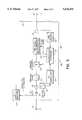
- FIG. 1shows a block diagram of a wireless telephone system
- FIG. 2shows a block diagram of a base station extender forming part of the telephone system of FIG. 1;
- FIG. 3shows a block diagram of a microcell extender forming part of the telephone system of FIG. 1;
- FIGS. 4a and 4bshow an amplifier and switch arrangement, forming part of the microcell extender of FIG. 3 (when configured to support TDD signals) in two different switched modes;
- FIG. 5shows a modification of the telephone system of FIG. 1
- FIG. 6shows a modification of the microcell extender of FIG. 3 for use in a frequency division duplex telephone system
- FIG. 7shows a block diagram of an amplifier arrangement forming part of the microcell extender of FIG. 6.
- FIG. 1shows a telephone system which includes a base station 10 for interfacing with a public switched telephone network (not shown) and, more particularly, for receiving baseband transmit signals from the public switched telephone network and outputting them as Time Division Duplex (TDD) or Frequency Division Duplex (FDD) transmit signals, and also for converting incoming TDD or FDD receive signals into baseband signals which are applied to the public switch telephone network.
- TDDTime Division Duplex
- FDDFrequency Division Duplex
- the base station 10is connected to an RF repeater arrangement which, in the present embodiment of the invention, comprises a first RF repeater part in the form of a base station extender 12 connected by signal conduits in the form of co-axial cables 14 and 16 to second RF repeater parts in the form of microcell extenders 18 and 19, which are provided with antennas 20 for exchanging the transmit and receive signals with a mobile wireless handset 22 as radio signals.
- RF repeater arrangementwhich, in the present embodiment of the invention, comprises a first RF repeater part in the form of a base station extender 12 connected by signal conduits in the form of co-axial cables 14 and 16 to second RF repeater parts in the form of microcell extenders 18 and 19, which are provided with antennas 20 for exchanging the transmit and receive signals with a mobile wireless handset 22 as radio signals.
- the above-described RF repeater arrangementhas the advantage that only one base station 10 is required to exchange the transmit and receive signals with the handset 22, provided that the handset 22 is located within the coverage zone of one or the other of the microcell extenders 18 and 19, so that the effective range of coverage of the base station 10 is thus increased by the use of the two microcell extenders 18 and 19.
- this telephone systemis not restricted to the use of only two microcell extenders 18 and 19, but may include a plurality of microcell extenders, which may be arranged with overlapping coverage zones so as to form a roamer corridor over which the handset 22 may roam while communicating with the base station 10.
- the transmit signalswhich are attenuated by the co-axial cables 14 and 16 as well as by the base station extender 12 and the microcell extenders 18 and 19, are subject to different attenuations, and correspondingly different signal level losses, between the base station extender 12 and the microcell extenders 18 and 19. Similar assymmetrics in attenuation losses may be increased by the addition of RF splitters to form sub-nets of microcell extenders off, say, the co-axial cable 16. Likewise, the receive signals are differently attenuated in passing from the antennas 20 to the base station 10. The present invention provides means for compensating these signal losses, as described below.
- a connector 24, which is connected to the base station 10is connected through a DC blocking capacitor 26, a high pass filter 28 and a second DC blocking capacitor 30 to a splitter 32, which is provided with two co-axial connectors 34 for connection to the co-axial cables 14 and 16.
- the base station 10will output the transmit signal for one millisecond at 944 MHz and will then receive the receive signal for one millisecond at 944 MHz.
- the transmission from the base station 10is typically at a high signal level, e.g. 10 milliWatts, while the receive signals are typically at a low power level, e.g. 1 nanoWatt.
- the basestation extender 12also has a power input conductor 36, which is connected from an alternating current supply (not shown) to a power supply 38, which outputs DC or low frequency AC power through the splitter 32 to the central conductors of the co-axial cables 34 for powering the remote microcell extenders 18 and 19.
- a directional coupler 40which connects a portion of the base station transmit signal to a first signal power level detector 42, which comprises a standard diode detector circuit.
- a first signal power level detector 42which comprises a standard diode detector circuit.
- the signal level at the detector 42produces a 1 millisecond pulse having a pulse height proportional to the magnitude of the transmit signal from the base station 10.
- This pulseis supplied to a microprocessor controller 44, which quantises the height of the pulse and encodes signal level data, representing the pulse height, in a data stream which is modulated, by a frequency shift keyed (FSK) modulator 46, onto a 10.7 MHz subcarder as data, as described in greater detail below.
- FSKfrequency shift keyed
- the modulated signal level datathen passes through a low pass filter 48 to a directional coupler 50, connected between the high pass filter 28 and the DC blocking capacitor 30, for transmission through the co-axial cables 14 and 16 to the microcell extenders 18 and 19.
- the microprocessor controller 44is implemented as a Motorola 68HC11 microprocessor with on-chip analog-to-digital converters.
- the directionality of the directional coupler, 40favours pickup of transmit signals from the base station 10, and does not favour pickup of receive signals from the handset 22.
- This directionalityin association with the difference in magnitude of the transmit and receive signals, allows the microprocessor controller 44 to differentiate simply between the transmit signals and the receive signals.
- the microprocessor controller 44can use the level detector 42 to define the transmit/receive timing necessary for synchronization of the second RF repeater parts. This method of deriving transmit receive timing is only useful once a handset has an established signal link with a base station (i.e. there is a valid transmit pulse from the base station to detect). This method is generally not applicable in the absence of a base station-handset link.
- the CSCmay be used to provide full transmit-receive timing at all time epochs, when used in conjunction with timing derived during a voice link.
- This transmit/receive timingis encoded into the FSK data stream by the microprocessor controller 44.
- the microcell extender 18is shown in greater detail in the block diagram of FIG. 3 is intended for TDD operation using the CT-2 Plus protocol, and it is to be understood that the microcell extenders 18 and 19 are similar to one another.
- the microcell extender 18has an input in the form of a co-axial connector 52 for connection to the co-axial cable 14.
- the co-axial connector 52is connected through a DC blocking capacitor 54, a directional coupler 56, a high pass filter 58 and a variable attenuator 60 to the input of a band limited TDD amplifier 62.
- the variable attenuator 60 and the amplifier 62form a signal level regulator for adjusting the levels of the transmit and receive signals.
- the output of the band limited TDD amplifier 62is connected through a directional coupler 64 and the output of the microcell extender 18 to the antenna 20.
- the co-axial connector 52is also connected to a DC switching regulator 64, the output of which provides DC power to all the electronic circuits in FIG. 3.
- the directional coupler 56supplies a portion of the incoming signal, from the co-axial cable 14, through a lowpass filter 66, to preferentially pass the 10.7 MHz signal, to a 10.7 MHz frequency shift keyed demodulator 68, the output of which contains the signal level data and the transmit-receive synchronization data provided, as described above, by the base station extender 12.
- a portion of the output of the band limited TDD amplifier 62is supplied by the directional coupler 64 to a second level detector 70, which detects the power level of the amplified transmit signal being supplied to the antenna 20 and provides this level to a control device in the form of a microprocessor controller 72.
- the level detector 70is implemented by a circuit identical to that of the level detector 42 in FIG. 2, i.e. a standard diode detector circuit. This will often result in some easing of temperature, tolerancing and linearity constraints since the use of identical level detectors 70 and 42 will typically result in these imperfections cancelling out.
- the signal level data output from the demodulator 68is compared in the microprocessor controller 72 with the quantised level from the level detector 70 to determine the difference in the levels of the transmit signal at the base station extender 12 and at the microcell extender 18 and the microprocessor controller 82 correspondingly adjusts the variable attenuator 60 so as to cause the level of the amplified transmit signal supplied to the antenna 20 to a predetermined ratio, e.g. 1:1, relative to that of the transmit signal detected by the level detector 42 of FIG. 2.
- the microcell extender 18will adjust its output so that the signal level at the antenna 20 is e.g. substantially identical to that at the output of the base station 10. The same holds true for the transmit signal level at the antenna 20 of the microcell extender 19.
- the directional coupler 64has a preference for coupling the transmit signal power to the power detector 70, and does not couple the receive signal power well.
- FIGS. 4a and 4bshow in greater detail the band limited time division duplex amplifier 62, which comprises a pair of amplifiers 72 and 74 connected in series, with a band limiting filter 76 connected between the amplifiers 72 and 74.
- the output of the amplifier 76 and the input of the amplifier 72are connected to respective terminals of a transfer switch indicated generally by reference numeral 78.
- the antenna 20 and a conductor 80, extending from the variable attenuator 60,are connected to two other terminals of the transfer switch 78.
- the transfer switch 78has two switch states. As shown in FIG. 4A, in a first switch state, which is a "receive" state in which the receive signal from the handset 22 is being received by the antenna 20, the transfer switch 78 connects the antenna 20 to the input of the amplifier 72 and also connects the output of the amplifier 74 to the variable attenuator 60, so that the receive signal is amplified by the amplifiers 72 and 74 and the gain is controlled by the variable attenuator 60 so as to counteract attenuation between the antenna 20 and the base station 10.
- a first switch statewhich is a "receive" state in which the receive signal from the handset 22 is being received by the antenna 20
- the transfer switch 78connects the antenna 20 to the input of the amplifier 72 and also connects the output of the amplifier 74 to the variable attenuator 60, so that the receive signal is amplified by the amplifiers 72 and 74 and the gain is controlled by the variable attenuator 60 so as to counteract attenuation between the antenna 20 and the base
- a second switch state of the transfer switch 78as illustrated in FIG. 4B, the conductor 80 from the variable attenuator 60 is connected to the input of the amplifier 72, while the output of the amplifier 74 is connected to the antenna 20.
- the transmit signalafter attenuation by the variable attenuator 60, is amplified by the amplifiers 72 and 74 to counteract signal loss between the base station and the antenna 20, as described above.
- the changes in the state of the transfer switch 78are controlled by control outputs from the microprocessor controller 72 in accordance with the timing derived from the transmit and receive signals.
- the amplifiers 72 and 74are used to amplify both the transmit signals and also the receive signals, and the transmit and receive signal gains are equal.
- the amplifier and switch arrangement shown in FIGS. 4A and 4Btherefore enables the microcell extender 18 to automatically compensate for both the transmit signal loss from the base station 10 to the antenna 20 and, also, the receive signal loss from the antenna 20 to the base station 10.
- the in-line amplifier unit 90is similar to the microcell extender 18 shown in FIG. 3, except that, the antenna 20 is omitted and is replaced by a co-axial connector 91 for connection to a co-axial cable 16A extending to the microcell extender 19. This arrangement allows microcell extender 10 to be connected to the base station by a physically longer, and hence more lossy, length of co-axial cable.
- a bypass conductor 92interconnects the co-axial connectors 52 and 91, i.e. the input and output of the in-line amplifier unit 90 and is provided with a switch 94. Closure of the switch 94 connects the 10.7 MHz subcarrier and the power from the connector 52 to the connector 91 and, thus, to the microcell 19.
- the output level of the in-amplifier unit 90When employing this in-line configuration, it is generally preferable to set the output level of the in-amplifier unit 90 lower than the usual transmit level. This allows the cascaded intermodulation budget for the in-line amplifier unit 90 and the end-of-line microcell extender 19 to be dominated solely by the end-of-line performance. Therefore, in operation, the closure of the switch 94 is detected by the microprocessor controller 72 and the variable attenuator 60 is adjusted by the microprocessor controller 72 in order to ensure that the detected signal level at connector 91 is, typically, one tenth of the signal output level at the base station 10. The in-line transmit gain will equal the in-line receive gain.
- the transmit and receive signalsare in the form of time division duplex signals.
- the above-described apparatus of FIGS. 1, 2 and 3can be readily adapted for frequency division duplex operation.
- the band limited FDD amplifier 100 of FIG. 6is illustrated in greater detail in FIG. 7.
- a conductor 102from the variable attenuator 60, is connected to a duplexer 104, which supplies the transmit signal through a band limiting filter 106 to a transmit amplifier 108, and which receives, from a band limiting filter 110 and a receive signal amplifier 112, the receive signal, which is then supplied through the conductor 102 to the variable attenuator 60.
- duplexers 104 and 114may, if required, be replaced by RF splitters/combiners.
- the transmit amplifier 108 and filter 106are physically distinct from the receive amplifier 112 and filter 110. Since the transmit signal levels are typically many orders of magnitude larger then the receive signal levels, the power detectors 42 (FIG. 2) and 70 (FIG. 3) can easily be used by the microprocessor 72 to distinguish the transmit power levels from the receive signal power levels.
- the receive amplifier 112 of FIG. 7has a known gain relative to the transmit amplifier 108, the receive path gain between the antenna 20 and the base station 10 is again well controlled and determined by the signal level adjustment employed for the transmit signal gain.
- the levelcorresponds to a signal of more than (say), one-tenth of a milliWatt, assume the level represents a transmit pulse.
- the levelis smaller than one-tenth of a milliWatt, assume the level represents a receive pulse.
- the microprocessor 72 of FIG. 3will typically operate as follows, for the concrete example of CT-2 Plus, which has 1 ms transmit and 1 ms receive epochs.
- start transmit pulseIf the data reads "start transmit pulse”, start a software counter that will place the transfer switch 78 into the receive position, in 1 milliseconds time, and into the transmit position in 2 millisecond time.
- switch 94If the switch 94 is open (end-of-line mode) multiply the signal level recorded by the level detector 70 by one.
- the microprocessor in FIG. 3may average the results of many measurements before deciding when the "start of transmit" really occurs, or what the transmit level really is.
- CT-2 Plusprovides a burst of CSC's in the absence of a voice link.
- the CSCsconsist of three bursts of 1 millisecond each, every 72 milliseconds.
- the microprocessor 72 of FIG. 2performs the additional step of creating its own “start of transmit” pulse for step 2 if previous "start of transmit” pulses indicate it is now a transmit epoch, but the level data reads "Rx present", in contradiction to prior experience.
- timing control softwarecan be employed for FDD operation vis-a-vis level control, but the timing control software may be limited to assisting in FDD-TDMA systems to selecting certain time slots for broadcast/reception by certain array members.
Landscapes
- Engineering & Computer Science (AREA)
- Computer Networks & Wireless Communication (AREA)
- Signal Processing (AREA)
- Radio Relay Systems (AREA)
- Mobile Radio Communication Systems (AREA)
- Transceivers (AREA)
- Input Circuits Of Receivers And Coupling Of Receivers And Audio Equipment (AREA)
Abstract
Description
Claims (12)
Priority Applications (7)
| Application Number | Priority Date | Filing Date | Title |
|---|---|---|---|
| US08/327,746US5634191A (en) | 1994-10-24 | 1994-10-24 | Self-adjusting RF repeater arrangements for wireless telephone systems |
| DE69506579TDE69506579D1 (en) | 1994-10-24 | 1995-10-20 | SELF-ADJUSTING RF AMPLIFIER ARRANGEMENT FOR WIRELESS TELEPHONE SYSTEM |
| EP95934025AEP0788686B1 (en) | 1994-10-24 | 1995-10-20 | Self-adjusting rf repeater arrangements for wireless telephone systems |
| AU36484/95AAU3648495A (en) | 1994-10-24 | 1995-10-20 | Self-adjusting rf repeater arrangements for wireless telephone systems |
| AT95934025TATE174460T1 (en) | 1994-10-24 | 1995-10-20 | SELF-ADAPTABLE RF AMPLIFIER ARRANGEMENT FOR WIRELESS TELEPHONE SYSTEM |
| KR1019970702602AKR970707655A (en) | 1994-10-24 | 1995-10-20 | SELF-ADJUSTING RF REPEATER ARRANGEMENTS FOR WIRELESS TELEPHONE SYSTEM FOR RADIO TELEPHONE SYSTEMS |
| PCT/CA1995/000591WO1996013103A1 (en) | 1994-10-24 | 1995-10-20 | Self-adjusting rf repeater arrangements for wireless telephone systems |
Applications Claiming Priority (1)
| Application Number | Priority Date | Filing Date | Title |
|---|---|---|---|
| US08/327,746US5634191A (en) | 1994-10-24 | 1994-10-24 | Self-adjusting RF repeater arrangements for wireless telephone systems |
Publications (1)
| Publication Number | Publication Date |
|---|---|
| US5634191Atrue US5634191A (en) | 1997-05-27 |
Family
ID=23277870
Family Applications (1)
| Application Number | Title | Priority Date | Filing Date |
|---|---|---|---|
| US08/327,746Expired - LifetimeUS5634191A (en) | 1994-10-24 | 1994-10-24 | Self-adjusting RF repeater arrangements for wireless telephone systems |
Country Status (7)
| Country | Link |
|---|---|
| US (1) | US5634191A (en) |
| EP (1) | EP0788686B1 (en) |
| KR (1) | KR970707655A (en) |
| AT (1) | ATE174460T1 (en) |
| AU (1) | AU3648495A (en) |
| DE (1) | DE69506579D1 (en) |
| WO (1) | WO1996013103A1 (en) |
Cited By (62)
| Publication number | Priority date | Publication date | Assignee | Title |
|---|---|---|---|---|
| US5832364A (en)* | 1995-10-06 | 1998-11-03 | Airnet Communications Corp. | Distributing wireless system carrier signals within a building using existing power line wiring |
| US6023628A (en)* | 1992-08-05 | 2000-02-08 | Pcs Wireless, Inc. | Base stations for TDD telephony and methods for operating the same |
| WO2000010264A1 (en)* | 1998-08-14 | 2000-02-24 | Phonex Corporation | Conversion and distribution of incoming wireless telephone signals using the power line |
| WO2000046937A1 (en)* | 1999-02-05 | 2000-08-10 | Interdigital Technology Corporation | Communication station with automatic cable loss compensation |
| WO2000052856A1 (en)* | 1999-03-01 | 2000-09-08 | Nokia Networks Oy | Apparatus, and associated method, for selectively modifying characteristics of the receive signal received at a receiving station |
| US6128470A (en)* | 1996-07-18 | 2000-10-03 | Ericsson Inc. | System and method for reducing cumulative noise in a distributed antenna network |
| WO2001033667A1 (en)* | 1999-10-29 | 2001-05-10 | Ball Aerospace & Technologies Corp. | Method and apparatus for carrying signals |
| US20020045461A1 (en)* | 2000-10-18 | 2002-04-18 | David Bongfeldt | Adaptive coverage area control in an on-frequency repeater |
| US20020119749A1 (en)* | 2001-02-28 | 2002-08-29 | Young-Min Oh | Repeater system having oscillation preventing function and automatic reverse output disabling function for non-subscriber and control method thereof |
| US20020155839A1 (en)* | 2001-04-18 | 2002-10-24 | Tait Electronics Limited | Allocation of control channel in a communication system |
| WO2003073643A1 (en)* | 2002-02-28 | 2003-09-04 | Nortel Networks Limited | Self-configuring repeater system and method |
| US20040004943A1 (en)* | 2002-07-02 | 2004-01-08 | Kim Ki-Chul | Base station system for mobile communication |
| EP1383258A2 (en) | 1999-02-05 | 2004-01-21 | Interdigital Technology Corporation | Base station with automatic cable loss compensation |
| US6690915B1 (en)* | 1999-08-31 | 2004-02-10 | Ntt Docomo, Inc. | Booster, monitoring apparatus, booster system, control method and monitoring method |
| US6768897B1 (en)* | 1997-09-30 | 2004-07-27 | Nokia Networks Oy | Method of adjusting frequency of cellular radio repeater |
| US20040166802A1 (en)* | 2003-02-26 | 2004-08-26 | Ems Technologies, Inc. | Cellular signal enhancer |
| US6904266B1 (en)* | 2002-02-19 | 2005-06-07 | Navini Networks, Inc. | Wireless enhancer using a switch matrix |
| US6990313B1 (en) | 2002-03-14 | 2006-01-24 | Sprint Communications Company L.P. | Wireless repeater with intelligent signal display |
| US20060189276A1 (en)* | 2004-12-08 | 2006-08-24 | Michael Halinski | Methods and systems for intelligent adaptive gain control |
| US7123939B1 (en) | 1999-02-05 | 2006-10-17 | Interdigital Technology Corporation | Communication station with automatic cable loss compensation |
| US20060291407A1 (en)* | 2005-06-24 | 2006-12-28 | Navini Networks, Inc. | Multiplexing system for time division duplex communication systems |
| US20070008939A1 (en)* | 2005-06-10 | 2007-01-11 | Adc Telecommunications, Inc. | Providing wireless coverage into substantially closed environments |
| US20070041339A1 (en)* | 2003-09-07 | 2007-02-22 | Serconet Ltd. | Modular outlet |
| US20070232228A1 (en)* | 2006-04-04 | 2007-10-04 | Mckay David L Sr | Wireless repeater with universal server base unit and modular donor antenna options |
| US20070275595A1 (en)* | 2004-02-16 | 2007-11-29 | Serconet Ltd. | Outlet add-on module |
| US20080076437A1 (en)* | 2006-09-26 | 2008-03-27 | Wilson Electronics | Cellular network amplifier with automated output power control |
| US20080125187A1 (en)* | 2006-11-03 | 2008-05-29 | Yu-Chuan Chang | Wireless transmission system suitable for large space and method thereof |
| US20080161055A1 (en)* | 2006-12-28 | 2008-07-03 | Lucent Technologies Inc. | Base station architecture using decentralized duplexers |
| US20080205606A1 (en)* | 2002-11-13 | 2008-08-28 | Serconet Ltd. | Addressable outlet, and a network using the same |
| US7565106B1 (en) | 2001-04-26 | 2009-07-21 | Sprint Spectrum L.P. | Wireless signal repeater with temperature and time display |
| US7633966B2 (en) | 2000-04-19 | 2009-12-15 | Mosaid Technologies Incorporated | Network combining wired and non-wired segments |
| US20090316609A1 (en)* | 2008-06-24 | 2009-12-24 | Lgc Wireless, Inc. | System and method for synchronized time-division duplex signal switching |
| US7813451B2 (en) | 2006-01-11 | 2010-10-12 | Mobileaccess Networks Ltd. | Apparatus and method for frequency shifting of a wireless signal and systems using frequency shifting |
| US20100302999A1 (en)* | 2009-05-29 | 2010-12-02 | Yan Hui | Method and apparatus for relaying in wireless networks |
| US7860084B2 (en) | 2001-10-11 | 2010-12-28 | Mosaid Technologies Incorporated | Outlet with analog signal adapter, a method for use thereof and a network using said outlet |
| US7903599B1 (en) | 2007-09-12 | 2011-03-08 | Sprint Spectrum L.P. | Call-detection algorithm for mitigating interference by low-cost internet-base-station (LCIB) pilot beacons with macro-network communications |
| US7974230B1 (en) | 2007-09-12 | 2011-07-05 | Sprint Spectrum L.P. | Mitigating interference by low-cost internet-base-station (LCIB) pilot beacons with macro-network communications |
| US7974653B1 (en) | 2008-08-12 | 2011-07-05 | Sprint Spectrum L.P. | Manually configuring low-cost Internet-base-station (LCIB) coverage using an associated mobile station |
| US8175649B2 (en) | 2008-06-20 | 2012-05-08 | Corning Mobileaccess Ltd | Method and system for real time control of an active antenna over a distributed antenna system |
| US8184598B1 (en) | 2008-05-29 | 2012-05-22 | Sprint Spectrum L.P. | Low-cost internet-base-station (LCIB) radio-frequency (RF) adaptation using stationary transceivers |
| US8325693B2 (en) | 2004-05-06 | 2012-12-04 | Corning Mobileaccess Ltd | System and method for carrying a wireless based signal over wiring |
| US8462683B2 (en) | 2011-01-12 | 2013-06-11 | Adc Telecommunications, Inc. | Distinct transport path for MIMO transmissions in distributed antenna systems |
| US8472579B2 (en) | 2010-07-28 | 2013-06-25 | Adc Telecommunications, Inc. | Distributed digital reference clock |
| US8532242B2 (en) | 2010-10-27 | 2013-09-10 | Adc Telecommunications, Inc. | Distributed antenna system with combination of both all digital transport and hybrid digital/analog transport |
| US8559339B1 (en) | 2007-11-14 | 2013-10-15 | Sprint Spectrum L.P. | Low-cost-internet-base-station-(LCIB) user-adaptation algorithm |
| US8594133B2 (en) | 2007-10-22 | 2013-11-26 | Corning Mobileaccess Ltd. | Communication system using low bandwidth wires |
| US8693342B2 (en) | 2011-10-28 | 2014-04-08 | Adc Telecommunications, Inc. | Distributed antenna system using time division duplexing scheme |
| US8804670B1 (en) | 2011-02-17 | 2014-08-12 | Sprint Spectrum L.P. | Method and system for management of inter-frequency handoff |
| US8897215B2 (en) | 2009-02-08 | 2014-11-25 | Corning Optical Communications Wireless Ltd | Communication system using cables carrying ethernet signals |
| US9178636B2 (en) | 2013-02-22 | 2015-11-03 | Adc Telecommunications, Inc. | Universal remote radio head |
| US9184960B1 (en) | 2014-09-25 | 2015-11-10 | Corning Optical Communications Wireless Ltd | Frequency shifting a communications signal(s) in a multi-frequency distributed antenna system (DAS) to avoid or reduce frequency interference |
| US9338823B2 (en) | 2012-03-23 | 2016-05-10 | Corning Optical Communications Wireless Ltd | Radio-frequency integrated circuit (RFIC) chip(s) for providing distributed antenna system functionalities, and related components, systems, and methods |
| US9420557B2 (en) | 2013-08-27 | 2016-08-16 | At&T Mobility Ii Llc | Radio repeater system for avoiding mobile device location interference |
| US9596322B2 (en) | 2014-06-11 | 2017-03-14 | Commscope Technologies Llc | Bitrate efficient transport through distributed antenna systems |
| US9787457B2 (en) | 2013-10-07 | 2017-10-10 | Commscope Technologies Llc | Systems and methods for integrating asynchronous signals in distributed antenna system with direct digital interface to base station |
| US10020850B2 (en) | 2013-02-22 | 2018-07-10 | Commscope Technologies Llc | Master reference for base station network interface sourced from distributed antenna system |
| US20180295672A1 (en)* | 2017-04-11 | 2018-10-11 | Wilson Electronics, Llc | Signal booster with coaxial cable connections |
| US10313893B2 (en) | 2013-04-29 | 2019-06-04 | Cellphone-Mate, Inc. | Apparatus and methods for radio frequency signal boosters |
| WO2019219682A1 (en) | 2018-05-14 | 2019-11-21 | Laird Dabendorf Gmbh | Antenna unit, transmission system and method for operating an antenna unit |
| US10499269B2 (en) | 2015-11-12 | 2019-12-03 | Commscope Technologies Llc | Systems and methods for assigning controlled nodes to channel interfaces of a controller |
| US10986164B2 (en) | 2004-01-13 | 2021-04-20 | May Patents Ltd. | Information device |
| US11683799B2 (en) | 2020-02-04 | 2023-06-20 | Nokia Technologies Oy | Communication system |
Families Citing this family (9)
| Publication number | Priority date | Publication date | Assignee | Title |
|---|---|---|---|---|
| FR2760925B1 (en)* | 1997-03-11 | 1999-05-14 | France Telecom | DEVICE FOR TWO-WAY AMPLIFICATION IN A REMOTE RADIO TERMINAL |
| IL161882A0 (en) | 2001-11-20 | 2005-11-20 | Qualcomm Inc | Reverse link power controlled repeater qualcomm incorporated |
| KR100412014B1 (en)* | 2001-12-13 | 2003-12-24 | 주식회사 에이스테크놀로지 | An intermediate frequency repeater enable to control the power and control method thereof |
| US7831263B2 (en) | 2002-11-08 | 2010-11-09 | Qualcomm Incorporated | Apparatus and method for determining the location of a repeater |
| MXPA06011461A (en) | 2004-04-05 | 2006-12-20 | Qualcomm Inc | Repeater with positioning capabilities. |
| JP2007532079A (en) | 2004-04-05 | 2007-11-08 | クゥアルコム・インコーポレイテッド | A repeater that reports detected neighbors |
| US7778596B2 (en) | 2004-07-29 | 2010-08-17 | Qualcomm Incorporated | Airlink sensing watermarking repeater |
| KR100870694B1 (en)* | 2006-12-11 | 2008-11-26 | (주)씨앤드에스 마이크로 웨이브 | IF Distributed Repeater with Compensator Compensating RF Cable Loss |
| DE102013207898A1 (en) | 2013-04-30 | 2014-10-30 | Novero Dabendorf Gmbh | Compensation of signal attenuation in the transmission of transmission signals of a mobile device |
Citations (10)
| Publication number | Priority date | Publication date | Assignee | Title |
|---|---|---|---|---|
| US3146397A (en)* | 1960-05-23 | 1964-08-25 | Collins Radio Co | Multiple-pole two-position dual-wafer ultra-high-frequency transmit-receive switch control |
| DE3126195A1 (en)* | 1981-07-03 | 1983-01-20 | Licentia Patent-Verwaltungs-Gmbh, 6000 Frankfurt | Common-wave radio network |
| US4563775A (en)* | 1983-08-18 | 1986-01-07 | Nec Corporation | Apparatus for controlling transmission output power |
| JPH03283724A (en)* | 1990-03-30 | 1991-12-13 | Nippon Telegr & Teleph Corp <Ntt> | Method for reducing propagation delay |
| US5095528A (en)* | 1988-10-28 | 1992-03-10 | Orion Industries, Inc. | Repeater with feedback oscillation control |
| US5187803A (en)* | 1990-01-18 | 1993-02-16 | Andrew Corporation | Regenerative rf bi-directional amplifier system |
| EP0599659A1 (en)* | 1992-11-26 | 1994-06-01 | Nec Corporation | Booster for use in combination with radio apparatus |
| US5321849A (en)* | 1991-05-22 | 1994-06-14 | Southwestern Bell Technology Resources, Inc. | System for controlling signal level at both ends of a transmission link based on a detected valve |
| US5321736A (en)* | 1992-01-03 | 1994-06-14 | Pcs Microcell International Inc. | Distributed RF repeater arrangement for cordless telephones |
| EP0605182A2 (en)* | 1992-12-30 | 1994-07-06 | Yoshiro Niki | Bidirectional repeater for mobile telephone system |
- 1994
- 1994-10-24USUS08/327,746patent/US5634191A/ennot_activeExpired - Lifetime
- 1995
- 1995-10-20ATAT95934025Tpatent/ATE174460T1/ennot_activeIP Right Cessation
- 1995-10-20DEDE69506579Tpatent/DE69506579D1/ennot_activeExpired - Lifetime
- 1995-10-20KRKR1019970702602Apatent/KR970707655A/ennot_activeWithdrawn
- 1995-10-20WOPCT/CA1995/000591patent/WO1996013103A1/ennot_activeApplication Discontinuation
- 1995-10-20AUAU36484/95Apatent/AU3648495A/ennot_activeAbandoned
- 1995-10-20EPEP95934025Apatent/EP0788686B1/ennot_activeExpired - Lifetime
Patent Citations (10)
| Publication number | Priority date | Publication date | Assignee | Title |
|---|---|---|---|---|
| US3146397A (en)* | 1960-05-23 | 1964-08-25 | Collins Radio Co | Multiple-pole two-position dual-wafer ultra-high-frequency transmit-receive switch control |
| DE3126195A1 (en)* | 1981-07-03 | 1983-01-20 | Licentia Patent-Verwaltungs-Gmbh, 6000 Frankfurt | Common-wave radio network |
| US4563775A (en)* | 1983-08-18 | 1986-01-07 | Nec Corporation | Apparatus for controlling transmission output power |
| US5095528A (en)* | 1988-10-28 | 1992-03-10 | Orion Industries, Inc. | Repeater with feedback oscillation control |
| US5187803A (en)* | 1990-01-18 | 1993-02-16 | Andrew Corporation | Regenerative rf bi-directional amplifier system |
| JPH03283724A (en)* | 1990-03-30 | 1991-12-13 | Nippon Telegr & Teleph Corp <Ntt> | Method for reducing propagation delay |
| US5321849A (en)* | 1991-05-22 | 1994-06-14 | Southwestern Bell Technology Resources, Inc. | System for controlling signal level at both ends of a transmission link based on a detected valve |
| US5321736A (en)* | 1992-01-03 | 1994-06-14 | Pcs Microcell International Inc. | Distributed RF repeater arrangement for cordless telephones |
| EP0599659A1 (en)* | 1992-11-26 | 1994-06-01 | Nec Corporation | Booster for use in combination with radio apparatus |
| EP0605182A2 (en)* | 1992-12-30 | 1994-07-06 | Yoshiro Niki | Bidirectional repeater for mobile telephone system |
Cited By (130)
| Publication number | Priority date | Publication date | Assignee | Title |
|---|---|---|---|---|
| US6023628A (en)* | 1992-08-05 | 2000-02-08 | Pcs Wireless, Inc. | Base stations for TDD telephony and methods for operating the same |
| US5832364A (en)* | 1995-10-06 | 1998-11-03 | Airnet Communications Corp. | Distributing wireless system carrier signals within a building using existing power line wiring |
| US6128470A (en)* | 1996-07-18 | 2000-10-03 | Ericsson Inc. | System and method for reducing cumulative noise in a distributed antenna network |
| US6768897B1 (en)* | 1997-09-30 | 2004-07-27 | Nokia Networks Oy | Method of adjusting frequency of cellular radio repeater |
| WO2000010264A1 (en)* | 1998-08-14 | 2000-02-24 | Phonex Corporation | Conversion and distribution of incoming wireless telephone signals using the power line |
| US6246868B1 (en)* | 1998-08-14 | 2001-06-12 | Phonex Corporation | Conversion and distribution of incoming wireless telephone signals using the power line |
| US7123939B1 (en) | 1999-02-05 | 2006-10-17 | Interdigital Technology Corporation | Communication station with automatic cable loss compensation |
| WO2000046937A1 (en)* | 1999-02-05 | 2000-08-10 | Interdigital Technology Corporation | Communication station with automatic cable loss compensation |
| EP1383258A2 (en) | 1999-02-05 | 2004-01-21 | Interdigital Technology Corporation | Base station with automatic cable loss compensation |
| EP1383258A3 (en)* | 1999-02-05 | 2004-11-24 | Interdigital Technology Corporation | Base station with automatic cable loss compensation |
| US20050250541A1 (en)* | 1999-02-05 | 2005-11-10 | Interdigital Technology Corporation | Communication station with automatic cable loss compensation |
| US7155257B2 (en) | 1999-02-05 | 2006-12-26 | Interdigital Technology Corporation | Communication station with automatic cable loss compensation |
| WO2000052856A1 (en)* | 1999-03-01 | 2000-09-08 | Nokia Networks Oy | Apparatus, and associated method, for selectively modifying characteristics of the receive signal received at a receiving station |
| US6374083B1 (en)* | 1999-03-01 | 2002-04-16 | Nokia Corporation | Apparatus, and associated method, for selectively modifying characteristics of the receive signal received at a receiving station |
| AU770706B2 (en)* | 1999-08-31 | 2004-02-26 | Ntt Docomo, Inc. | Booster, monitoring apparatus, booster system, control method and monitoring method |
| US6690915B1 (en)* | 1999-08-31 | 2004-02-10 | Ntt Docomo, Inc. | Booster, monitoring apparatus, booster system, control method and monitoring method |
| US6268827B1 (en)* | 1999-10-29 | 2001-07-31 | Ball Aerospace & Technologies Corp. | Method and apparatus for carrying signals having different frequencies in a space-deployed antenna system |
| WO2001033667A1 (en)* | 1999-10-29 | 2001-05-10 | Ball Aerospace & Technologies Corp. | Method and apparatus for carrying signals |
| US8982903B2 (en) | 2000-04-19 | 2015-03-17 | Conversant Intellectual Property Management Inc. | Network combining wired and non-wired segments |
| US7933297B2 (en) | 2000-04-19 | 2011-04-26 | Mosaid Technologies Incorporated | Network combining wired and non-wired segments |
| US7715441B2 (en) | 2000-04-19 | 2010-05-11 | Mosaid Technologies Incorporated | Network combining wired and non-wired segments |
| US8867506B2 (en) | 2000-04-19 | 2014-10-21 | Conversant Intellectual Property Management Incorporated | Network combining wired and non-wired segments |
| US7636373B2 (en) | 2000-04-19 | 2009-12-22 | Mosaid Technologies Incorporated | Network combining wired and non-wired segments |
| US7633966B2 (en) | 2000-04-19 | 2009-12-15 | Mosaid Technologies Incorporated | Network combining wired and non-wired segments |
| US7876767B2 (en) | 2000-04-19 | 2011-01-25 | Mosaid Technologies Incorporated | Network combining wired and non-wired segments |
| US8848725B2 (en) | 2000-04-19 | 2014-09-30 | Conversant Intellectual Property Management Incorporated | Network combining wired and non-wired segments |
| US8289991B2 (en) | 2000-04-19 | 2012-10-16 | Mosaid Technologies Incorporated | Network combining wired and non-wired segments |
| US8982904B2 (en) | 2000-04-19 | 2015-03-17 | Conversant Intellectual Property Management Inc. | Network combining wired and non-wired segments |
| US8873586B2 (en) | 2000-04-19 | 2014-10-28 | Conversant Intellectual Property Management Incorporated | Network combining wired and non-wired segments |
| US8873575B2 (en) | 2000-04-19 | 2014-10-28 | Conversant Intellectual Property Management Incorporated | Network combining wired and non-wired segments |
| US20020045461A1 (en)* | 2000-10-18 | 2002-04-18 | David Bongfeldt | Adaptive coverage area control in an on-frequency repeater |
| US6748194B2 (en)* | 2001-02-28 | 2004-06-08 | Korea Telecom M.Com Co., Ltd. | Repeater system having oscillation preventing function and automatic reverse output disabling function for non-subscriber and control method thereof |
| US20020119749A1 (en)* | 2001-02-28 | 2002-08-29 | Young-Min Oh | Repeater system having oscillation preventing function and automatic reverse output disabling function for non-subscriber and control method thereof |
| US20020155839A1 (en)* | 2001-04-18 | 2002-10-24 | Tait Electronics Limited | Allocation of control channel in a communication system |
| US7565106B1 (en) | 2001-04-26 | 2009-07-21 | Sprint Spectrum L.P. | Wireless signal repeater with temperature and time display |
| US7860084B2 (en) | 2001-10-11 | 2010-12-28 | Mosaid Technologies Incorporated | Outlet with analog signal adapter, a method for use thereof and a network using said outlet |
| US6904266B1 (en)* | 2002-02-19 | 2005-06-07 | Navini Networks, Inc. | Wireless enhancer using a switch matrix |
| WO2003073643A1 (en)* | 2002-02-28 | 2003-09-04 | Nortel Networks Limited | Self-configuring repeater system and method |
| US7050758B2 (en) | 2002-02-28 | 2006-05-23 | Nortel Networks Limited | Self-configuring repeater system and method |
| US20030211828A1 (en)* | 2002-02-28 | 2003-11-13 | Nortel Networks Limited | Self-configuring repeater system and method |
| US6990313B1 (en) | 2002-03-14 | 2006-01-24 | Sprint Communications Company L.P. | Wireless repeater with intelligent signal display |
| US7035587B1 (en) | 2002-03-14 | 2006-04-25 | Sprint Spectrum L.P. | Method and system for decreasing noise from wireless repeaters |
| US7209703B1 (en) | 2002-03-14 | 2007-04-24 | Sprint Spectrum L.P. | Wireless repeater with intelligent signal display |
| US7684435B2 (en)* | 2002-07-02 | 2010-03-23 | Samsung Electronics Co., Ltd. | Base station system for mobile communication |
| US20040004943A1 (en)* | 2002-07-02 | 2004-01-08 | Kim Ki-Chul | Base station system for mobile communication |
| US7911992B2 (en) | 2002-11-13 | 2011-03-22 | Mosaid Technologies Incorporated | Addressable outlet, and a network using the same |
| US20080205606A1 (en)* | 2002-11-13 | 2008-08-28 | Serconet Ltd. | Addressable outlet, and a network using the same |
| US20040166802A1 (en)* | 2003-02-26 | 2004-08-26 | Ems Technologies, Inc. | Cellular signal enhancer |
| US7688841B2 (en) | 2003-07-09 | 2010-03-30 | Mosaid Technologies Incorporated | Modular outlet |
| US7690949B2 (en) | 2003-09-07 | 2010-04-06 | Mosaid Technologies Incorporated | Modular outlet |
| US20070041339A1 (en)* | 2003-09-07 | 2007-02-22 | Serconet Ltd. | Modular outlet |
| US10986165B2 (en) | 2004-01-13 | 2021-04-20 | May Patents Ltd. | Information device |
| US10986164B2 (en) | 2004-01-13 | 2021-04-20 | May Patents Ltd. | Information device |
| US20070275595A1 (en)* | 2004-02-16 | 2007-11-29 | Serconet Ltd. | Outlet add-on module |
| US8542819B2 (en) | 2004-02-16 | 2013-09-24 | Mosaid Technologies Incorporated | Outlet add-on module |
| US8243918B2 (en) | 2004-02-16 | 2012-08-14 | Mosaid Technologies Incorporated | Outlet add-on module |
| US8325759B2 (en) | 2004-05-06 | 2012-12-04 | Corning Mobileaccess Ltd | System and method for carrying a wireless based signal over wiring |
| US8325693B2 (en) | 2004-05-06 | 2012-12-04 | Corning Mobileaccess Ltd | System and method for carrying a wireless based signal over wiring |
| US20060189276A1 (en)* | 2004-12-08 | 2006-08-24 | Michael Halinski | Methods and systems for intelligent adaptive gain control |
| US20100215028A1 (en)* | 2005-06-10 | 2010-08-26 | Adc Telecommunications, Inc. | Providing wireless coverage into substantially closed environments |
| US20070008939A1 (en)* | 2005-06-10 | 2007-01-11 | Adc Telecommunications, Inc. | Providing wireless coverage into substantially closed environments |
| US20060291407A1 (en)* | 2005-06-24 | 2006-12-28 | Navini Networks, Inc. | Multiplexing system for time division duplex communication systems |
| US7656957B2 (en)* | 2005-06-24 | 2010-02-02 | Cisco Technology, Inc. | Multiplexing system for time division duplex communication systems |
| US7813451B2 (en) | 2006-01-11 | 2010-10-12 | Mobileaccess Networks Ltd. | Apparatus and method for frequency shifting of a wireless signal and systems using frequency shifting |
| US20110206088A1 (en)* | 2006-01-11 | 2011-08-25 | Mobileaccess Networks Ltd. | Apparatus and method for frequency shifting of a wireless signal and systems using frequency shifting |
| US8184681B2 (en) | 2006-01-11 | 2012-05-22 | Corning Mobileaccess Ltd | Apparatus and method for frequency shifting of a wireless signal and systems using frequency shifting |
| US20070232228A1 (en)* | 2006-04-04 | 2007-10-04 | Mckay David L Sr | Wireless repeater with universal server base unit and modular donor antenna options |
| US20080076437A1 (en)* | 2006-09-26 | 2008-03-27 | Wilson Electronics | Cellular network amplifier with automated output power control |
| US7783318B2 (en)* | 2006-09-26 | 2010-08-24 | Wilson Electronics | Cellular network amplifier with automated output power control |
| US20080125187A1 (en)* | 2006-11-03 | 2008-05-29 | Yu-Chuan Chang | Wireless transmission system suitable for large space and method thereof |
| US20080161055A1 (en)* | 2006-12-28 | 2008-07-03 | Lucent Technologies Inc. | Base station architecture using decentralized duplexers |
| US8023999B2 (en) | 2006-12-28 | 2011-09-20 | Alcatel Lucent | Base station architecture using decentralized duplexers |
| US7903599B1 (en) | 2007-09-12 | 2011-03-08 | Sprint Spectrum L.P. | Call-detection algorithm for mitigating interference by low-cost internet-base-station (LCIB) pilot beacons with macro-network communications |
| US7974230B1 (en) | 2007-09-12 | 2011-07-05 | Sprint Spectrum L.P. | Mitigating interference by low-cost internet-base-station (LCIB) pilot beacons with macro-network communications |
| US9813229B2 (en) | 2007-10-22 | 2017-11-07 | Corning Optical Communications Wireless Ltd | Communication system using low bandwidth wires |
| US8594133B2 (en) | 2007-10-22 | 2013-11-26 | Corning Mobileaccess Ltd. | Communication system using low bandwidth wires |
| US8559339B1 (en) | 2007-11-14 | 2013-10-15 | Sprint Spectrum L.P. | Low-cost-internet-base-station-(LCIB) user-adaptation algorithm |
| US9549301B2 (en) | 2007-12-17 | 2017-01-17 | Corning Optical Communications Wireless Ltd | Method and system for real time control of an active antenna over a distributed antenna system |
| US8184598B1 (en) | 2008-05-29 | 2012-05-22 | Sprint Spectrum L.P. | Low-cost internet-base-station (LCIB) radio-frequency (RF) adaptation using stationary transceivers |
| US8175649B2 (en) | 2008-06-20 | 2012-05-08 | Corning Mobileaccess Ltd | Method and system for real time control of an active antenna over a distributed antenna system |
| US8310963B2 (en) | 2008-06-24 | 2012-11-13 | Adc Telecommunications, Inc. | System and method for synchronized time-division duplex signal switching |
| US20090316609A1 (en)* | 2008-06-24 | 2009-12-24 | Lgc Wireless, Inc. | System and method for synchronized time-division duplex signal switching |
| US7974653B1 (en) | 2008-08-12 | 2011-07-05 | Sprint Spectrum L.P. | Manually configuring low-cost Internet-base-station (LCIB) coverage using an associated mobile station |
| US8897215B2 (en) | 2009-02-08 | 2014-11-25 | Corning Optical Communications Wireless Ltd | Communication system using cables carrying ethernet signals |
| US20100302999A1 (en)* | 2009-05-29 | 2010-12-02 | Yan Hui | Method and apparatus for relaying in wireless networks |
| US8837659B2 (en) | 2010-07-28 | 2014-09-16 | Adc Telecommunications, Inc. | Distributed digital reference clock |
| USRE48342E1 (en) | 2010-07-28 | 2020-12-01 | Commscope Technologies Llc | Distributed digital reference clock |
| USRE48351E1 (en) | 2010-07-28 | 2020-12-08 | Commscope Technologies Llc | Distributed digital reference clock |
| US8472579B2 (en) | 2010-07-28 | 2013-06-25 | Adc Telecommunications, Inc. | Distributed digital reference clock |
| USRE48757E1 (en) | 2010-10-27 | 2021-09-28 | Commscope Technologies Llc | Distributed antenna system with combination of both all digital transport and hybrid digital/analog transport |
| US8532242B2 (en) | 2010-10-27 | 2013-09-10 | Adc Telecommunications, Inc. | Distributed antenna system with combination of both all digital transport and hybrid digital/analog transport |
| USRE47160E1 (en) | 2010-10-27 | 2018-12-11 | Commscope Technologies Llc | Distributed antenna system with combination of both all digital transport and hybrid digital/analog transport |
| US8743756B2 (en) | 2011-01-12 | 2014-06-03 | Adc Telecommunications, Inc. | Distinct transport path for MIMO transmissions in distributed antenna systems |
| US8462683B2 (en) | 2011-01-12 | 2013-06-11 | Adc Telecommunications, Inc. | Distinct transport path for MIMO transmissions in distributed antenna systems |
| US8804670B1 (en) | 2011-02-17 | 2014-08-12 | Sprint Spectrum L.P. | Method and system for management of inter-frequency handoff |
| US9219520B2 (en) | 2011-10-28 | 2015-12-22 | Adc Telecommunications, Inc. | Distributed antenna system using time division duplexing scheme |
| US8693342B2 (en) | 2011-10-28 | 2014-04-08 | Adc Telecommunications, Inc. | Distributed antenna system using time division duplexing scheme |
| US9338823B2 (en) | 2012-03-23 | 2016-05-10 | Corning Optical Communications Wireless Ltd | Radio-frequency integrated circuit (RFIC) chip(s) for providing distributed antenna system functionalities, and related components, systems, and methods |
| US9948329B2 (en) | 2012-03-23 | 2018-04-17 | Corning Optical Communications Wireless, LTD | Radio-frequency integrated circuit (RFIC) chip(s) for providing distributed antenna system functionalities, and related components, systems, and methods |
| US10020850B2 (en) | 2013-02-22 | 2018-07-10 | Commscope Technologies Llc | Master reference for base station network interface sourced from distributed antenna system |
| US9178636B2 (en) | 2013-02-22 | 2015-11-03 | Adc Telecommunications, Inc. | Universal remote radio head |
| US11329701B2 (en) | 2013-02-22 | 2022-05-10 | Commscope Technologies Llc | Master reference for base station network interface sourced from distributed antenna system |
| US10567044B2 (en) | 2013-02-22 | 2020-02-18 | Commscope Technologies Llc | Universal remote radio head |
| US9504039B2 (en) | 2013-02-22 | 2016-11-22 | Commscope Technologies Llc | Universal remote radio head |
| US10128918B2 (en) | 2013-02-22 | 2018-11-13 | Commscope Technologies Llc | Universal remote radio head |
| US10855338B2 (en) | 2013-02-22 | 2020-12-01 | Commscope Technologies Llc | Master reference for base station network interface sourced from distributed antenna system |
| US11228921B2 (en) | 2013-04-29 | 2022-01-18 | Cellphone-Mate, Inc. | Apparatus and methods for radio frequency signal boosters |
| US10313893B2 (en) | 2013-04-29 | 2019-06-04 | Cellphone-Mate, Inc. | Apparatus and methods for radio frequency signal boosters |
| US9735909B2 (en) | 2013-08-27 | 2017-08-15 | At&T Mobility Ii Llc | Radio repeater system for avoiding mobile device location interference |
| US9420557B2 (en) | 2013-08-27 | 2016-08-16 | At&T Mobility Ii Llc | Radio repeater system for avoiding mobile device location interference |
| US9787457B2 (en) | 2013-10-07 | 2017-10-10 | Commscope Technologies Llc | Systems and methods for integrating asynchronous signals in distributed antenna system with direct digital interface to base station |
| US10205584B2 (en) | 2013-10-07 | 2019-02-12 | Commscope Technologies Llc | Systems and methods for integrating asynchronous signals in distributed antenna system with direct digital interface to base station |
| US9954584B2 (en) | 2014-06-11 | 2018-04-24 | Commscope Technologies Llc | Bitrate efficient transport through distributed antenna systems |
| US10020851B2 (en) | 2014-06-11 | 2018-07-10 | Commscope Technologies Llc | Bitrate efficient transport through distributed antenna systems |
| US9596322B2 (en) | 2014-06-11 | 2017-03-14 | Commscope Technologies Llc | Bitrate efficient transport through distributed antenna systems |
| US9686379B2 (en) | 2014-06-11 | 2017-06-20 | Commscope Technologies Llc | Bitrate efficient transport through distributed antenna systems |
| US10333591B2 (en) | 2014-06-11 | 2019-06-25 | Commscope Technologies Llc | Bitrate efficient transport through distributed antenna systems |
| US9515855B2 (en) | 2014-09-25 | 2016-12-06 | Corning Optical Communications Wireless Ltd | Frequency shifting a communications signal(s) in a multi-frequency distributed antenna system (DAS) to avoid or reduce frequency interference |
| US9184960B1 (en) | 2014-09-25 | 2015-11-10 | Corning Optical Communications Wireless Ltd | Frequency shifting a communications signal(s) in a multi-frequency distributed antenna system (DAS) to avoid or reduce frequency interference |
| US9253003B1 (en) | 2014-09-25 | 2016-02-02 | Corning Optical Communications Wireless Ltd | Frequency shifting a communications signal(S) in a multi-frequency distributed antenna system (DAS) to avoid or reduce frequency interference |
| US10499269B2 (en) | 2015-11-12 | 2019-12-03 | Commscope Technologies Llc | Systems and methods for assigning controlled nodes to channel interfaces of a controller |
| US10485057B2 (en)* | 2017-04-11 | 2019-11-19 | Wilson Electronics, Llc | Signal booster with coaxial cable connections |
| US10925115B2 (en)* | 2017-04-11 | 2021-02-16 | Wilson Electronics, Llc | Signal booster with coaxial cable connections |
| US10512120B2 (en)* | 2017-04-11 | 2019-12-17 | Wilson Electronics, Llc | Signal booster with coaxial cable connections |
| US20180295672A1 (en)* | 2017-04-11 | 2018-10-11 | Wilson Electronics, Llc | Signal booster with coaxial cable connections |
| US20190069342A1 (en)* | 2017-04-11 | 2019-02-28 | Wilson Electronics, Llc | Signal booster with coaxial cable connections |
| US20200092947A1 (en)* | 2017-04-11 | 2020-03-19 | Wilson Electronics, Llc | Signal booster with coaxial cable connections |
| WO2019219682A1 (en) | 2018-05-14 | 2019-11-21 | Laird Dabendorf Gmbh | Antenna unit, transmission system and method for operating an antenna unit |
| US12003260B2 (en) | 2018-05-14 | 2024-06-04 | Molex Technologies Gmbh | Antenna unit, transmission system and method for operating an antenna unit |
| US11683799B2 (en) | 2020-02-04 | 2023-06-20 | Nokia Technologies Oy | Communication system |
Also Published As
| Publication number | Publication date |
|---|---|
| EP0788686B1 (en) | 1998-12-09 |
| KR970707655A (en) | 1997-12-01 |
| EP0788686A1 (en) | 1997-08-13 |
| AU3648495A (en) | 1996-05-15 |
| ATE174460T1 (en) | 1998-12-15 |
| WO1996013103A1 (en) | 1996-05-02 |
| DE69506579D1 (en) | 1999-01-21 |
Similar Documents
| Publication | Publication Date | Title |
|---|---|---|
| US5634191A (en) | Self-adjusting RF repeater arrangements for wireless telephone systems | |
| AU695358B2 (en) | Cellular radio system, repeater and base station | |
| US6480702B1 (en) | Apparatus and method for distributing wireless communications signals to remote cellular antennas | |
| CA2087285C (en) | Rf repeaters for time division duplex cordless telephone systems | |
| US6690915B1 (en) | Booster, monitoring apparatus, booster system, control method and monitoring method | |
| EP2018714B1 (en) | Wireless repeater with master/slave configuration | |
| US6201795B1 (en) | Method and apparatus for mitigating interference in a communication system | |
| US5115463A (en) | Extended cordless telephone system | |
| EP1091508B1 (en) | Repeating installation using telephone and dedicated line | |
| UA44762C2 (en) | RADIO TELEPHONE RECEIVING AND TRANSMISSION SYSTEM AND METHOD OF RECEIVING RF SIGNAL | |
| US7965977B2 (en) | Remote antenna system | |
| US6513163B1 (en) | Embedded forward reference and control | |
| CA2134365C (en) | Self-adjusting rf repeater arrangements for wireless telephone systems | |
| GB2198316A (en) | Transceiver using local oscillator leakage radiation | |
| CA2041705A1 (en) | Method and apparatus for providing wireless communications between remote locations | |
| CA2232615A1 (en) | Dual transmitter arrangement with back-up switching | |
| JP3300552B2 (en) | Repeater using optical cable | |
| CN1169802A (en) | Self-adjusting radio frequency transponders for wireless telephone systems | |
| US5867792A (en) | Radio communication system | |
| KR100377935B1 (en) | Sysyem for monitoring adjacent channel power in a wireless base station | |
| KR100668106B1 (en) | Time delay correction device of base station system | |
| KR20030084078A (en) | Wireless lan service system using mobile telecommunication network | |
| HK1004971A (en) | Self-adjusting rf repeater arrangements for wireless telephone systems | |
| KR101029979B1 (en) | Wireless communication relay device and method | |
| JPS63149926A (en) | Ordering signal transmission system |
Legal Events
| Date | Code | Title | Description |
|---|---|---|---|
| STCF | Information on status: patent grant | Free format text:PATENTED CASE | |
| AS | Assignment | Owner name:ALLEN TELECOM INC., OHIO Free format text:ASSIGNMENT OF ASSIGNORS INTEREST;ASSIGNOR:PCS WIRELESS INTERNATIONAL, INC.;REEL/FRAME:008848/0796 Effective date:19971010 | |
| FEPP | Fee payment procedure | Free format text:PAYER NUMBER DE-ASSIGNED (ORIGINAL EVENT CODE: RMPN); ENTITY STATUS OF PATENT OWNER: LARGE ENTITY Free format text:PAT HLDR NO LONGER CLAIMS SMALL ENT STAT AS SMALL BUSINESS (ORIGINAL EVENT CODE: LSM2); ENTITY STATUS OF PATENT OWNER: LARGE ENTITY Free format text:PAYOR NUMBER ASSIGNED (ORIGINAL EVENT CODE: ASPN); ENTITY STATUS OF PATENT OWNER: LARGE ENTITY | |
| FPAY | Fee payment | Year of fee payment:4 | |
| AS | Assignment | Owner name:KEYBANK NATIONAL ASSOCIATION, OHIO Free format text:SECURITY AGREEMENT;ASSIGNOR:ALLEN TELECOM, INC.;REEL/FRAME:015017/0844 Effective date:20020131 | |
| AS | Assignment | Owner name:KEYBANK NATIONAL ASSOCIATION, OHIO Free format text:SECURITY INTEREST;ASSIGNOR:ALLEN TELECOM, INC.;REEL/FRAME:012822/0425 Effective date:20020131 | |
| AS | Assignment | Owner name:ALLEN TELECOM INC., OHIO Free format text:RELEASE OF SECURITY INTEREST;ASSIGNOR:KEYBANK NATIONAL ASSOCIATION, AS COLLATERAL AGENT;REEL/FRAME:015027/0518 Effective date:20030716 | |
| FPAY | Fee payment | Year of fee payment:8 | |
| AS | Assignment | Owner name:ALLEN TELECOM LLC, ILLINOIS Free format text:MERGER;ASSIGNORS:ALLEN TELECOM INC.;ADIRONDACKS, LLC;REEL/FRAME:020166/0074 Effective date:20030715 | |
| AS | Assignment | Owner name:BANK OF AMERICA, N.A., AS ADMINISTRATIVE AGENT, CA Free format text:SECURITY AGREEMENT;ASSIGNORS:COMMSCOPE, INC. OF NORTH CAROLINA;ALLEN TELECOM, LLC;ANDREW CORPORATION;REEL/FRAME:020362/0241 Effective date:20071227 Owner name:BANK OF AMERICA, N.A., AS ADMINISTRATIVE AGENT,CAL Free format text:SECURITY AGREEMENT;ASSIGNORS:COMMSCOPE, INC. OF NORTH CAROLINA;ALLEN TELECOM, LLC;ANDREW CORPORATION;REEL/FRAME:020362/0241 Effective date:20071227 | |
| FPAY | Fee payment | Year of fee payment:12 | |
| AS | Assignment | Owner name:ANDREW LLC (F/K/A ANDREW CORPORATION), NORTH CAROL Free format text:PATENT RELEASE;ASSIGNOR:BANK OF AMERICA, N.A., AS ADMINISTRATIVE AGENT;REEL/FRAME:026039/0005 Effective date:20110114 Owner name:COMMSCOPE, INC. OF NORTH CAROLINA, NORTH CAROLINA Free format text:PATENT RELEASE;ASSIGNOR:BANK OF AMERICA, N.A., AS ADMINISTRATIVE AGENT;REEL/FRAME:026039/0005 Effective date:20110114 Owner name:ALLEN TELECOM LLC, NORTH CAROLINA Free format text:PATENT RELEASE;ASSIGNOR:BANK OF AMERICA, N.A., AS ADMINISTRATIVE AGENT;REEL/FRAME:026039/0005 Effective date:20110114 | |
| AS | Assignment | Owner name:JPMORGAN CHASE BANK, N.A., AS COLLATERAL AGENT, NE Free format text:SECURITY AGREEMENT;ASSIGNORS:ALLEN TELECOM LLC, A DELAWARE LLC;ANDREW LLC, A DELAWARE LLC;COMMSCOPE, INC. OF NORTH CAROLINA, A NORTH CAROLINA CORPORATION;REEL/FRAME:026276/0363 Effective date:20110114 | |
| AS | Assignment | Owner name:JPMORGAN CHASE BANK, N.A., AS COLLATERAL AGENT, NE Free format text:SECURITY AGREEMENT;ASSIGNORS:ALLEN TELECOM LLC, A DELAWARE LLC;ANDREW LLC, A DELAWARE LLC;COMMSCOPE, INC OF NORTH CAROLINA, A NORTH CAROLINA CORPORATION;REEL/FRAME:026272/0543 Effective date:20110114 | |
| AS | Assignment | Owner name:REDWOOD SYSTEMS, INC., NORTH CAROLINA Free format text:RELEASE BY SECURED PARTY;ASSIGNOR:JPMORGAN CHASE BANK, N.A.;REEL/FRAME:048840/0001 Effective date:20190404 Owner name:COMMSCOPE TECHNOLOGIES LLC, NORTH CAROLINA Free format text:RELEASE BY SECURED PARTY;ASSIGNOR:JPMORGAN CHASE BANK, N.A.;REEL/FRAME:048840/0001 Effective date:20190404 Owner name:ANDREW LLC, NORTH CAROLINA Free format text:RELEASE BY SECURED PARTY;ASSIGNOR:JPMORGAN CHASE BANK, N.A.;REEL/FRAME:048840/0001 Effective date:20190404 Owner name:COMMSCOPE, INC. OF NORTH CAROLINA, NORTH CAROLINA Free format text:RELEASE BY SECURED PARTY;ASSIGNOR:JPMORGAN CHASE BANK, N.A.;REEL/FRAME:048840/0001 Effective date:20190404 Owner name:ALLEN TELECOM LLC, ILLINOIS Free format text:RELEASE BY SECURED PARTY;ASSIGNOR:JPMORGAN CHASE BANK, N.A.;REEL/FRAME:048840/0001 Effective date:20190404 Owner name:ANDREW LLC, NORTH CAROLINA Free format text:RELEASE BY SECURED PARTY;ASSIGNOR:JPMORGAN CHASE BANK, N.A.;REEL/FRAME:049260/0001 Effective date:20190404 Owner name:ALLEN TELECOM LLC, ILLINOIS Free format text:RELEASE BY SECURED PARTY;ASSIGNOR:JPMORGAN CHASE BANK, N.A.;REEL/FRAME:049260/0001 Effective date:20190404 Owner name:COMMSCOPE, INC. OF NORTH CAROLINA, NORTH CAROLINA Free format text:RELEASE BY SECURED PARTY;ASSIGNOR:JPMORGAN CHASE BANK, N.A.;REEL/FRAME:049260/0001 Effective date:20190404 Owner name:REDWOOD SYSTEMS, INC., NORTH CAROLINA Free format text:RELEASE BY SECURED PARTY;ASSIGNOR:JPMORGAN CHASE BANK, N.A.;REEL/FRAME:049260/0001 Effective date:20190404 Owner name:COMMSCOPE TECHNOLOGIES LLC, NORTH CAROLINA Free format text:RELEASE BY SECURED PARTY;ASSIGNOR:JPMORGAN CHASE BANK, N.A.;REEL/FRAME:049260/0001 Effective date:20190404 |