US5633885A - Frequency chirp control and compensation for obtaining broad bandwidth ultrashort optical pulses from wavelength-tunable lasers - Google Patents
Frequency chirp control and compensation for obtaining broad bandwidth ultrashort optical pulses from wavelength-tunable lasersDownload PDFInfo
- Publication number
- US5633885A US5633885AUS08/312,912US31291294AUS5633885AUS 5633885 AUS5633885 AUS 5633885AUS 31291294 AUS31291294 AUS 31291294AUS 5633885 AUS5633885 AUS 5633885A
- Authority
- US
- United States
- Prior art keywords
- wavelength
- compensating
- tunable laser
- frequency chirp
- compensation
- Prior art date
- Legal status (The legal status is an assumption and is not a legal conclusion. Google has not performed a legal analysis and makes no representation as to the accuracy of the status listed.)
- Expired - Lifetime
Links
- 230000003287optical effectEffects0.000titleclaimsabstractdescription45
- 238000000034methodMethods0.000claimsabstractdescription23
- 238000001228spectrumMethods0.000claimsabstractdescription9
- 239000000835fiberSubstances0.000claimsabstractdescription8
- 239000006185dispersionSubstances0.000claimsdescription32
- 230000000694effectsEffects0.000claimsdescription13
- 238000012937correctionMethods0.000claimsdescription5
- 239000003990capacitorSubstances0.000claimsdescription3
- 230000005540biological transmissionEffects0.000claimsdescription2
- 230000010354integrationEffects0.000claims2
- 239000002131composite materialSubstances0.000abstract1
- 230000003595spectral effectEffects0.000description5
- 239000013307optical fiberSubstances0.000description3
- 230000006835compressionEffects0.000description2
- 238000007906compressionMethods0.000description2
- 238000011161developmentMethods0.000description2
- 238000002347injectionMethods0.000description2
- 239000007924injectionSubstances0.000description2
- 239000004065semiconductorSubstances0.000description2
- 238000007493shaping processMethods0.000description2
- 230000003321amplificationEffects0.000description1
- 230000001447compensatory effectEffects0.000description1
- 238000010276constructionMethods0.000description1
- 238000007796conventional methodMethods0.000description1
- 239000013078crystalSubstances0.000description1
- 238000000354decomposition reactionMethods0.000description1
- 230000001419dependent effectEffects0.000description1
- 238000010586diagramMethods0.000description1
- 238000005516engineering processMethods0.000description1
- 239000000463materialSubstances0.000description1
- 238000005259measurementMethods0.000description1
- 238000012986modificationMethods0.000description1
- 230000004048modificationEffects0.000description1
- 238000003199nucleic acid amplification methodMethods0.000description1
- 230000000737periodic effectEffects0.000description1
- 238000012545processingMethods0.000description1
- 230000001902propagating effectEffects0.000description1
- 230000001960triggered effectEffects0.000description1
Images


Classifications
- H—ELECTRICITY
- H01—ELECTRIC ELEMENTS
- H01S—DEVICES USING THE PROCESS OF LIGHT AMPLIFICATION BY STIMULATED EMISSION OF RADIATION [LASER] TO AMPLIFY OR GENERATE LIGHT; DEVICES USING STIMULATED EMISSION OF ELECTROMAGNETIC RADIATION IN WAVE RANGES OTHER THAN OPTICAL
- H01S5/00—Semiconductor lasers
- H01S5/06—Arrangements for controlling the laser output parameters, e.g. by operating on the active medium
- H01S5/062—Arrangements for controlling the laser output parameters, e.g. by operating on the active medium by varying the potential of the electrodes
- H01S5/0625—Arrangements for controlling the laser output parameters, e.g. by operating on the active medium by varying the potential of the electrodes in multi-section lasers
- H—ELECTRICITY
- H01—ELECTRIC ELEMENTS
- H01S—DEVICES USING THE PROCESS OF LIGHT AMPLIFICATION BY STIMULATED EMISSION OF RADIATION [LASER] TO AMPLIFY OR GENERATE LIGHT; DEVICES USING STIMULATED EMISSION OF ELECTROMAGNETIC RADIATION IN WAVE RANGES OTHER THAN OPTICAL
- H01S3/00—Lasers, i.e. devices using stimulated emission of electromagnetic radiation in the infrared, visible or ultraviolet wave range
- H01S3/005—Optical devices external to the laser cavity, specially adapted for lasers, e.g. for homogenisation of the beam or for manipulating laser pulses, e.g. pulse shaping
- H01S3/0057—Temporal shaping, e.g. pulse compression, frequency chirping
- H—ELECTRICITY
- H01—ELECTRIC ELEMENTS
- H01S—DEVICES USING THE PROCESS OF LIGHT AMPLIFICATION BY STIMULATED EMISSION OF RADIATION [LASER] TO AMPLIFY OR GENERATE LIGHT; DEVICES USING STIMULATED EMISSION OF ELECTROMAGNETIC RADIATION IN WAVE RANGES OTHER THAN OPTICAL
- H01S5/00—Semiconductor lasers
- H01S5/005—Optical components external to the laser cavity, specially adapted therefor, e.g. for homogenisation or merging of the beams or for manipulating laser pulses, e.g. pulse shaping
- H01S5/0057—Optical components external to the laser cavity, specially adapted therefor, e.g. for homogenisation or merging of the beams or for manipulating laser pulses, e.g. pulse shaping for temporal shaping, e.g. pulse compression, frequency chirping
- H—ELECTRICITY
- H01—ELECTRIC ELEMENTS
- H01S—DEVICES USING THE PROCESS OF LIGHT AMPLIFICATION BY STIMULATED EMISSION OF RADIATION [LASER] TO AMPLIFY OR GENERATE LIGHT; DEVICES USING STIMULATED EMISSION OF ELECTROMAGNETIC RADIATION IN WAVE RANGES OTHER THAN OPTICAL
- H01S5/00—Semiconductor lasers
- H01S5/04—Processes or apparatus for excitation, e.g. pumping, e.g. by electron beams
- H01S5/042—Electrical excitation ; Circuits therefor
- H01S5/0428—Electrical excitation ; Circuits therefor for applying pulses to the laser
- H—ELECTRICITY
- H01—ELECTRIC ELEMENTS
- H01S—DEVICES USING THE PROCESS OF LIGHT AMPLIFICATION BY STIMULATED EMISSION OF RADIATION [LASER] TO AMPLIFY OR GENERATE LIGHT; DEVICES USING STIMULATED EMISSION OF ELECTROMAGNETIC RADIATION IN WAVE RANGES OTHER THAN OPTICAL
- H01S5/00—Semiconductor lasers
- H01S5/06—Arrangements for controlling the laser output parameters, e.g. by operating on the active medium
- H01S5/062—Arrangements for controlling the laser output parameters, e.g. by operating on the active medium by varying the potential of the electrodes
- H01S5/0625—Arrangements for controlling the laser output parameters, e.g. by operating on the active medium by varying the potential of the electrodes in multi-section lasers
- H01S5/06255—Controlling the frequency of the radiation
- H01S5/06256—Controlling the frequency of the radiation with DBR-structure
- H—ELECTRICITY
- H01—ELECTRIC ELEMENTS
- H01S—DEVICES USING THE PROCESS OF LIGHT AMPLIFICATION BY STIMULATED EMISSION OF RADIATION [LASER] TO AMPLIFY OR GENERATE LIGHT; DEVICES USING STIMULATED EMISSION OF ELECTROMAGNETIC RADIATION IN WAVE RANGES OTHER THAN OPTICAL
- H01S5/00—Semiconductor lasers
- H01S5/10—Construction or shape of the optical resonator, e.g. extended or external cavity, coupled cavities, bent-guide, varying width, thickness or composition of the active region
- H01S5/12—Construction or shape of the optical resonator, e.g. extended or external cavity, coupled cavities, bent-guide, varying width, thickness or composition of the active region the resonator having a periodic structure, e.g. in distributed feedback [DFB] lasers
- H01S5/1206—Construction or shape of the optical resonator, e.g. extended or external cavity, coupled cavities, bent-guide, varying width, thickness or composition of the active region the resonator having a periodic structure, e.g. in distributed feedback [DFB] lasers having a non constant or multiplicity of periods
- H01S5/1212—Chirped grating
Definitions
- the present inventionis directed to optical signal processing and more particularly to a method of, and apparatus for controlling and compensating for high order chirp nonlinearities in an optical signal.
- a bandwidth limited pulseis the shortest pulse for a given spectrum, and is characterized in that all of its spectral components overlap in time (have the same phase).
- the duration ⁇ of a bandwidth limited pulseis inversely proportional to the width of its frequency spectrum ⁇ v: ⁇ ⁇ 1/ ⁇ v.
- Non-bandwidth limited pulseshave a frequency chirp, which has to be compensated to obtain bandwidth limited pulses.
- the existing compensation techniquesdeal mostly with pulses from mode-locked lasers. In mode-locked laser systems, chirp control and compensation is accomplished by using dispersive delay lines inside or outside the laser cavity. For this purpose prisms, diffraction gratings, Gires-Tournois interferometers, or multilayer mirrors are used inside or outside the laser cavity.
- the magnitude of the dispersionis ⁇ 50 fs 2 and is sufficient to achieve bandwidth-limited pulses of ⁇ 14 fs with the spectral width of >60 nm.
- the ultimate achievement of these techniqueswas the generation of the shortest optical pulses, which are only 6-10 fs long and contain just a few optical cycles.
- Galvanauskas et al.As discussed in Galvanauskas et al., El. Lett. 27, 2394 (1991), which is hereby incorporated by reference herein, Galvanauskas et al., Appl. Phys. Lett. 63, 1742 (1993), which is hereby incorporated by reference herein, and Galvanauskas et al., Opt. Lett. 19, 1043 (1994), which is hereby incorporated by reference herein, recent development of compact tunable lasers (e.g., three-section distributed Bragg-reflection, three-section distributed feedback, tunable twin guide, vertical-coupler, coupled-cavity laser diodes, etc.) have triggered the development of a new short pulse generation technique.
- compact tunable laserse.g., three-section distributed Bragg-reflection, three-section distributed feedback, tunable twin guide, vertical-coupler, coupled-cavity laser diodes, etc.
- This techniqueuses a fast tuning of the emission wavelength of a tunable laser to obtain broad bandwidth pulses, which can be compressed down to ultrashort durations.
- Systems using this techniquehave a number of properties such as robustness, compactness, reliability, arbitrary pulse repetition rate, high pulse energies and relatively low cost, which makes them an interesting and promising alternative to conventional mode-locked lasers.
- the demonstrated bandwidth of continuous tuningwas ⁇ 10 nm.
- the potential tuning rangeis as broad as the gain bandwidth of the laser medium and can exceed 100 nm, which corresponds to a bandwidth-limited duration of less than 100 fs.
- a continuously-tunable lasercontains a gain element, a phase modulator to shift the emission frequency and a tunable narrow-band filter to allow only one longitudinal mode in the cavity.
- the laser cavityshould be sufficiently short and the speed of the phase modulator and the tunable filter should be sufficiently high.
- the chirp durationcan be ⁇ 1 ns so that compression with a dispersive delay line (e.g., diffraction gratings or a standard optical fiber) would be easy.
- a dispersive delay linee.g., diffraction gratings or a standard optical fiber
- FIG. 2aOne example is a three-section tunable laser diode shown in FIG. 2a.
- Other possible tunable structuresare also shown in FIG. 2b-f, which differ from each other via the combination of the three basic components.
- all existing structures which can be fast wavelength tunedare semiconductor laser diodes. Wavelength tuning is performed by changing the refractive index of a semiconductor material either by varying the carrier concentration (carrier injection) or by using the electrooptic effect.
- other types of tunable compact laser structurese.g., short cavity fiber lasers, waveguide lasers, and compact solid-state lasers can also be developed using integrated electrooptical, carrier-injection or other types of electrically controlled modulators and filters.
- ⁇ 0is the central frequency of the pulse, which for a bandwidth-limited pulse, should be ⁇ (t) ⁇ 0 .
- the present inventionaccomplishes these and other significant objectives by controlling the chirp and compensating for the higher order chirp nonlinearities by using nonlinear frequency tuning and/or specifically designed nonlinearly dispersive elements inside or outside the laser cavity.
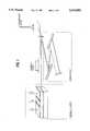
- FIG. 1is an illustration of the generation of ultrashort pulses using fast wavelength tuning
- FIGS. 2a-fshow various laser structures suitable for fast wavelength tuning
- FIG. 3is a schematic of an arrangement in accordance with the present invention, for frequency chirp control and compensation
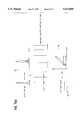
- FIG. 4shows an example of a broad-bandwidth electric integrator
- FIG. 5ais a graphical representation of examples of synthesized quadratic electric waveforms
- FIG. 5bis a graphical representation of examples of synthesized cubic electric waveforms
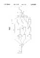
- FIG. 6is a block diagram showing an arrangement for obtaining the arbitrarily shaped electrical waveform.
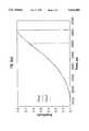
- FIG. 7ashows the effect of a linearly chirped Bragg grating on the chirp of reflected pulses
- FIG. 7bshows the effect of a nonlinearly chirped Bragg grating on the chirp of reflected pulses.
- the general arrangement of the preferred embodimentconsists of a controller 12, a tunable laser 10 and dispersive components either inside or outside the laser cavity such as the chirp compensation structure 11.
- the tunable laser 10comprises a narrow band reflecting filter 1, phase modulator 2, and laser gain medium 3, while the chirp compensation structure 11 has a nonlinear dispersion component 4 and a linearly dispersive compressor 5.
- the tuning voltageshould have the shape:
- the required waveform represented by equation (2) for controlling the chirp nonlinearitiescan be obtained with specially designed pulse shaping techniques.
- electric step-like pulses with very fast rise time and a longer durationshould be generated, such as electric pulses with 300-600 ps rise times and 2-3 ns durations.
- broad bandwidth electrical integratorscan/be used to shape the electric waveform.
- any desired term in the expansion equation (2)can be obtained. For example, by integrating a step-like pulse, a linear increase is obtained; by integrating this linear increase, a quadratic increase is formed, etc.
- FIG. 4shows one example of a broad-bandwidth integrator which is a circuit having a capacitor 41 connected in parallel with a coaxial transmission line 42.
- the capacitor valuesshould range from ⁇ 1 to 20 pF.
- FIG. 5shows examples of quadratic and cubic electric waveforms obtained experimentally with such integrators, where the ideal calculated waveforms substantially agree with the experimental results.
- FIG. 6shows an example of the realization of a practical waveform shaper in accordance with the present invention.
- Nanosecond electric pulses with a fast rise timeare generated with a pulse generator and split into a number of channels 22-25, such that the number of channels 22-25 is equal to the number of correction orders required.
- Each of the channels 23-25contains one or more integrators 26-31 in a given channel connected in series, such that the number of integrators 26-31 determines the order of the correction a particular channel 23-25 is used to control.
- the final waveformis obtained after combining all the waveforms from each channel 22-25 into one after suitable amplification via amplifiers A, this signal then being used as the driving signal for the laser source.
- Waveformscan be split and combined with standard RF power splitters 20 and combiners 21. By controlling the magnitude of the electric signal in each of the channels using amplifiers A, the magnitude of each chirp nonlinearity is controlled.
- chirp components with an order higher than twowere reduced below the resolution limit of the measurements, and the magnitude of quadratic chirp was reduced by a factor of ⁇ 100 100.
- the estimated quadratic dispersion required to compensate this chirpwas ⁇ 10 10 fs 3 , which can be obtained with a standard compensation arrangement.
- a sequence of short (picosecond) pulsescan be generated, and the magnitude of each pulse controlled to get the sampled version of the required waveform. Then, by passing this sequence through a filter, a continuous waveform can be obtained.
- dispersive optical components for compensating the frequency-chirp nonlinearitiescan be used outside or even inside the laser cavity.
- Optical meanscan be used as an addition to the electric control to precisely eliminate the remaining chirp, or as the main compensating component. If used in addition to electric control, the requirements on the compensation magnitude and number of orders is eased, and traditional methods with diffraction gratings, prisms, interferometers or multilayer mirrors can be used.
- dispersive optical componentsare used as the main compensatory component(s)
- new dispersive components with controllable and large nonlinear dispersionare required.
- Thisfor example, can be realized using a Bragg grating.
- linearly chirped in-fiber Bragg gratingscan be used, as discussed in Ouellette, Opt. Lett. 12, 847 (1987), which is hereby incorporated by reference herein.
- nonlinearly chirped Bragg gratingsare used to compensate nonlinear frequency chirp.
- the quadratic chirp profile of a Bragg gratingwill compensate quadratic frequency chirp, cubic will compensate cubic, etc.
- the dispersive structure for compensating any nonlinear chirpcan be designed and fabricated.
- the dispersion that can be achieved with a fiber gratingis sufficient to compensate for nonlinearly chirped pulses from a fast-tuned laser.
- the magnitude of the grating dispersionis determined by the length of the grating and the reflection bandwidth.
- gratings with length ⁇ 1 cm and bandwidth of ⁇ 10-20 nmhave been reported in Kashyap et al., Electr. Lett 30, 996 (1994), which is hereby incorporated by reference herein. These gratings are sufficient to compensate frequency deviation from linear chirp of up to ⁇ 100 ps over the bandwidth of up to 10-20 nm.
- second order dispersionwould be approximately 10 11 -10 12 fs 3 .
- FIG. 7(a) and (b)the effect of linearly and nonlinearly chirped Bragg gratings on the frequency ⁇ chirp of reflected optical pulses is shown.
- Different wavelength components of an optical pulse incident into a chirped Bragg gratingare reflected at different longitudinal positions in the grating.
- v gis the group velocity of light in the structure
- ⁇ Lis the distance from the beginning of the grating to the position at which the spectral component is reflected.
- nis the refractive index and ⁇ (x) is position-dependent period of the grating. Therefore, the frequency chirp introduced by such a grating on a broad-bandwidth optical pulse will follow the functional dependence of ⁇ (x).
- a linearly chirped gratingwill produce linearly chirped optical pulses, a quadratically chirped grating will induce second order chirp, etc.
- Such chirped Bragg gratingscan also be implemented in media other than optical fiber, such as waveguides or bulk Bragg gratings.
- Unchirped in-waveguide Bragg gratings at presentare widely used in tunable laser diodes as narrow-band optical filters (e.g., in a three-section DBR or n DFB laser diodes). By introducing nonlinear spatial chirp with quadratic and higher order terms into such a reflector, intracavity compensation of nonlinear chirp can be achieved.
- Bulk Bragg gratingscan be obtained using acousto-optical modulation where RF electric waveforms induce a periodic variation of the refractive index in an acousto-optic crystal.
- a suitably chirped Bragg reflectorcan be formed for an optical wave propagating along the direction of the acoustic wave.
- the advantage of such a chirp compensation methodis that the magnitude of the chirp nonlinearity can be controlled by adjusting the chirp of the RF waveform.
Landscapes
- Physics & Mathematics (AREA)
- Condensed Matter Physics & Semiconductors (AREA)
- General Physics & Mathematics (AREA)
- Electromagnetism (AREA)
- Optics & Photonics (AREA)
- Lasers (AREA)
- Optical Modulation, Optical Deflection, Nonlinear Optics, Optical Demodulation, Optical Logic Elements (AREA)
Abstract
Description
The present invention is directed to optical signal processing and more particularly to a method of, and apparatus for controlling and compensating for high order chirp nonlinearities in an optical signal.
A bandwidth limited pulse is the shortest pulse for a given spectrum, and is characterized in that all of its spectral components overlap in time (have the same phase). The duration Δπ of a bandwidth limited pulse is inversely proportional to the width of its frequency spectrum Δv:Δτ ∝1/Δv. Non-bandwidth limited pulses have a frequency chirp, which has to be compensated to obtain bandwidth limited pulses. The existing compensation techniques deal mostly with pulses from mode-locked lasers. In mode-locked laser systems, chirp control and compensation is accomplished by using dispersive delay lines inside or outside the laser cavity. For this purpose prisms, diffraction gratings, Gires-Tournois interferometers, or multilayer mirrors are used inside or outside the laser cavity. One example of chirp compensation is reported in Fork et al., Opt. Lett. 12, 483 (1987), which is hereby incorporated by reference herein. A diffraction grating pair and a four prism arrangement outside the laser with respective first and second order dispersions of ˜1000 fs2 and ˜1000 fs3 were used to compensate the linear and quadratic frequency chirp. Another example in A. Stingl et al., Opt. Lett. 19, 204 (1994), which is hereby incorporated by reference herein, reports the use of specifically designed multilayer mirrors to compensate for the frequency chirp inside the cavity of a mode-locked Ti:sapphire laser. This allows first order chirp to be eliminated. The magnitude of the dispersion is ˜50 fs2 and is sufficient to achieve bandwidth-limited pulses of <14 fs with the spectral width of >60 nm. The ultimate achievement of these techniques was the generation of the shortest optical pulses, which are only 6-10 fs long and contain just a few optical cycles.
As discussed in Galvanauskas et al., El. Lett. 27, 2394 (1991), which is hereby incorporated by reference herein, Galvanauskas et al., Appl. Phys. Lett. 63, 1742 (1993), which is hereby incorporated by reference herein, and Galvanauskas et al., Opt. Lett. 19, 1043 (1994), which is hereby incorporated by reference herein, recent development of compact tunable lasers (e.g., three-section distributed Bragg-reflection, three-section distributed feedback, tunable twin guide, vertical-coupler, coupled-cavity laser diodes, etc.) have triggered the development of a new short pulse generation technique. This technique uses a fast tuning of the emission wavelength of a tunable laser to obtain broad bandwidth pulses, which can be compressed down to ultrashort durations. Systems using this technique have a number of properties such as robustness, compactness, reliability, arbitrary pulse repetition rate, high pulse energies and relatively low cost, which makes them an interesting and promising alternative to conventional mode-locked lasers. In the past, the demonstrated bandwidth of continuous tuning was ˜10 nm. However, the potential tuning range is as broad as the gain bandwidth of the laser medium and can exceed 100 nm, which corresponds to a bandwidth-limited duration of less than 100 fs.
The potential broad tuning range has not before been fully utilized, because the chirp nonlinearity of the pulses from a tunable laser is high, and the conventional techniques fail to compensate such chirp. In Galvanauskas et al., Opt. Lett. 19, 1043 (1994), it was demonstrated experimentally that only 1-2 nm bandwidth pulses can be compressed down to the bandwidth limit (˜2 ps pulse duration) when a three-section DBR laser diode and a diffraction grating pair compressor are used. With additional nonlinear compression these pulses could be further shortened down to 230 fs, but the quality of the pulses is lost, in that broad pedestals and satellite pulses appear.
Fast Tuning Techniques and Chirp Nonlinearities
With fast tuning techniques, chirped pulses are generated directly from a tunable laser and compressed outside the laser cavity, as shown in FIG. 1. In general, a continuously-tunable laser contains a gain element, a phase modulator to shift the emission frequency and a tunable narrow-band filter to allow only one longitudinal mode in the cavity. To attain fast tuning, the laser cavity should be sufficiently short and the speed of the phase modulator and the tunable filter should be sufficiently high. The chirp duration can be ˜1 ns so that compression with a dispersive delay line (e.g., diffraction gratings or a standard optical fiber) would be easy. Such speed can be attained by electrical means, see A. Galvanauskas et al., Appl. Phys. Lett. Vol. 63, p. 1742-1744, 1993.
One example is a three-section tunable laser diode shown in FIG. 2a. Other possible tunable structures are also shown in FIG. 2b-f, which differ from each other via the combination of the three basic components. At present, all existing structures which can be fast wavelength tuned are semiconductor laser diodes. Wavelength tuning is performed by changing the refractive index of a semiconductor material either by varying the carrier concentration (carrier injection) or by using the electrooptic effect. In principle, other types of tunable compact laser structures, e.g., short cavity fiber lasers, waveguide lasers, and compact solid-state lasers can also be developed using integrated electrooptical, carrier-injection or other types of electrically controlled modulators and filters.
It is useful to define the chirp nonlinearity. The instantaneous frequency of a chirped pulse can be expanded into the power series:
ω(t)=ω.sub.0 +ω.sub.1 t+ω.sub.w t.sup.2 +ω.sub.3 t.sup.3 + (1)
Here ω0 is the central frequency of the pulse, which for a bandwidth-limited pulse, should be ω(t)≡ω0. Other terms, which should be absent in a bandwidth limited pulse, correspond to the first, second and higher orders of the frequency chirp respectively.
If the chirped pulses, which are generated by the fast tuning, would have only the linear term in the decomposition equation (1), bandwidth-limited pulses would be easy to attain with any linear dispersive delay line. However, a number of processes inside the cavity of a tunable laser add higher order chirp terms and typically the magnitudes of these terms are too high to be compensated by standard means.
It is an object of the present invention to introduce new techniques for compensating the nonlinear frequency chirp from a fast-tuned laser. It is another object of the present invention to provide for the generation of pulses with much shorter durations than before. It is a further object of the present invention to obtain bandwidth-limited pulses with spectra containing the complete tuning range of a tunable laser.
The present invention accomplishes these and other significant objectives by controlling the chirp and compensating for the higher order chirp nonlinearities by using nonlinear frequency tuning and/or specifically designed nonlinearly dispersive elements inside or outside the laser cavity.
In order that the invention be fully understood, a preferred embodiment will now be described with reference to the accompanying drawings, in which:
FIG. 1 is an illustration of the generation of ultrashort pulses using fast wavelength tuning;
FIGS. 2a-f show various laser structures suitable for fast wavelength tuning;
FIG. 3 is a schematic of an arrangement in accordance with the present invention, for frequency chirp control and compensation;
FIG. 4 shows an example of a broad-bandwidth electric integrator;
FIG. 5a is a graphical representation of examples of synthesized quadratic electric waveforms;
FIG. 5b is a graphical representation of examples of synthesized cubic electric waveforms;
FIG. 6 is a block diagram showing an arrangement for obtaining the arbitrarily shaped electrical waveform.
FIG. 7a shows the effect of a linearly chirped Bragg grating on the chirp of reflected pulses; and
FIG. 7b shows the effect of a nonlinearly chirped Bragg grating on the chirp of reflected pulses.
As shown in FIG. 3, the general arrangement of the preferred embodiment consists of acontroller 12, atunable laser 10 and dispersive components either inside or outside the laser cavity such as the chirp compensation structure 11. Thetunable laser 10 comprises a narrowband reflecting filter 1,phase modulator 2, and laser gain medium 3, while the chirp compensation structure 11 has a nonlinear dispersion component 4 and a linearlydispersive compressor 5.
In Galvanauskas et al., El. Lett. 27, 2394 (1991), and Galvanauskas et al., Appl. Phys. Lett. 63, 1742 (1993), fast tuning was demonstrated using nanosecond electric pulses with a subnanosecond rise-time. In order to control the nonlinear frequency chirp, more complex electric tuning has to be accomplished. For an electrically tuned device, the tuning voltage should have the shape:
V(t)=a.sub.0 +a.sub.1 t+a.sub.2 t.sup.2 +a.sub.3 t.sup.3 + (2)
Then by proper choice of the magnitudes of terms in equation (2), nonlinear terms in the chirp expansion (1) can be compensated.
The required waveform represented by equation (2) for controlling the chirp nonlinearities can be obtained with specially designed pulse shaping techniques. First, electric step-like pulses with very fast rise time and a longer duration should be generated, such as electric pulses with 300-600 ps rise times and 2-3 ns durations. Then, broad bandwidth electrical integrators can/be used to shape the electric waveform. By connecting integrators in series, any desired term in the expansion equation (2) can be obtained. For example, by integrating a step-like pulse, a linear increase is obtained; by integrating this linear increase, a quadratic increase is formed, etc.
FIG. 4 shows one example of a broad-bandwidth integrator which is a circuit having a capacitor 41 connected in parallel with acoaxial transmission line 42. For 0.5 to 2 ns pulse shaping, the capacitor values should range from ˜1 to 20 pF. FIG. 5 shows examples of quadratic and cubic electric waveforms obtained experimentally with such integrators, where the ideal calculated waveforms substantially agree with the experimental results.
FIG. 6 shows an example of the realization of a practical waveform shaper in accordance with the present invention. Nanosecond electric pulses with a fast rise time are generated with a pulse generator and split into a number of channels 22-25, such that the number of channels 22-25 is equal to the number of correction orders required. Each of the channels 23-25 contains one or more integrators 26-31 in a given channel connected in series, such that the number of integrators 26-31 determines the order of the correction a particular channel 23-25 is used to control. The final waveform is obtained after combining all the waveforms from each channel 22-25 into one after suitable amplification via amplifiers A, this signal then being used as the driving signal for the laser source. Waveforms can be split and combined with standardRF power splitters 20 andcombiners 21. By controlling the magnitude of the electric signal in each of the channels using amplifiers A, the magnitude of each chirp nonlinearity is controlled.
This technique of electric chirp compensation was verified experimentally. Frequency chirped pulses with a wavelength-bandwidth of 4 nm were generated with a three-section DBR laser diode as shown in FIG. 2a. Linear chirp was compensated with a diffraction grating pair, and the remaining chirp was measured with a spectrometer and a streak-camera. It was estimated that to compensate the remaining quadratic chirp, when no electric control of the chirp nonlinearity was used, dispersion of ˜1012 fs3 would be required. Higher order chirp components must also be compensated in this case. When the suitable electric waveform was generated using a construction as in FIG. 6 and used to control the chirp, chirp components with an order higher than two were reduced below the resolution limit of the measurements, and the magnitude of quadratic chirp was reduced by a factor of ˜100 100. The estimated quadratic dispersion required to compensate this chirp was ˜1010 fs3, which can be obtained with a standard compensation arrangement.
There are other techniques for generating picosecond to nanosecond arbitrarily shaped electric waveforms. For example, a sequence of short (picosecond) pulses can be generated, and the magnitude of each pulse controlled to get the sampled version of the required waveform. Then, by passing this sequence through a filter, a continuous waveform can be obtained.
For optical chirp compensation, dispersive optical components for compensating the frequency-chirp nonlinearities can be used outside or even inside the laser cavity. Optical means can be used as an addition to the electric control to precisely eliminate the remaining chirp, or as the main compensating component. If used in addition to electric control, the requirements on the compensation magnitude and number of orders is eased, and traditional methods with diffraction gratings, prisms, interferometers or multilayer mirrors can be used.
In the second case, where dispersive optical components are used as the main compensatory component(s), new dispersive components with controllable and large nonlinear dispersion are required. This, for example, can be realized using a Bragg grating. For compensating linear chirp, linearly chirped in-fiber Bragg gratings can be used, as discussed in Ouellette, Opt. Lett. 12, 847 (1987), which is hereby incorporated by reference herein. In the invention, nonlinearly chirped Bragg gratings are used to compensate nonlinear frequency chirp. The quadratic chirp profile of a Bragg grating will compensate quadratic frequency chirp, cubic will compensate cubic, etc. By combining such gratings either in series or overlapping them in an optical fiber, the dispersive structure for compensating any nonlinear chirp can be designed and fabricated. The dispersion that can be achieved with a fiber grating is sufficient to compensate for nonlinearly chirped pulses from a fast-tuned laser. The magnitude of the grating dispersion is determined by the length of the grating and the reflection bandwidth. With existing technology, gratings with length ˜1 cm and bandwidth of ˜10-20 nm have been reported in Kashyap et al., Electr.Lett 30, 996 (1994), which is hereby incorporated by reference herein. These gratings are sufficient to compensate frequency deviation from linear chirp of up to ˜100 ps over the bandwidth of up to 10-20 nm. For example, second order dispersion would be approximately 1011 -1012 fs3.
In FIG. 7(a) and (b) the effect of linearly and nonlinearly chirped Bragg gratings on the frequency υ chirp of reflected optical pulses is shown. Different wavelength components of an optical pulse incident into a chirped Bragg grating are reflected at different longitudinal positions in the grating. For the spectral component with wavelength λ the time delay introduced by the grating is Δπ=2ΔL/vg. Here vg is the group velocity of light in the structure and ΔL is the distance from the beginning of the grating to the position at which the spectral component is reflected. The spectral component λ will be reflected at the position x determined by the Bragg condition λB =2nΛ(x). Here n is the refractive index and Λ(x) is position-dependent period of the grating. Therefore, the frequency chirp introduced by such a grating on a broad-bandwidth optical pulse will follow the functional dependence of Λ(x). A linearly chirped grating will produce linearly chirped optical pulses, a quadratically chirped grating will induce second order chirp, etc. As a practical example, numerical calculations of the dispersion properties of linearly and quadratically chirped gratings performed by the inventors reveal that for a 2.47 mm long grating with Λaver =0.247 μm and a 15 nm reflection bandwidth at 1.5 μm, linear grating provides linear dispersion of 0.7 ps2 and quadratic grating exhibits second order group-velocity dispersion of ˜108 fs3.
Such chirped Bragg gratings can also be implemented in media other than optical fiber, such as waveguides or bulk Bragg gratings. Unchirped in-waveguide Bragg gratings at present are widely used in tunable laser diodes as narrow-band optical filters (e.g., in a three-section DBR or n DFB laser diodes). By introducing nonlinear spatial chirp with quadratic and higher order terms into such a reflector, intracavity compensation of nonlinear chirp can be achieved.
Bulk Bragg gratings can be obtained using acousto-optical modulation where RF electric waveforms induce a periodic variation of the refractive index in an acousto-optic crystal. By controlling the chirp of the RF waveform, a suitably chirped Bragg reflector can be formed for an optical wave propagating along the direction of the acoustic wave. The advantage of such a chirp compensation method is that the magnitude of the chirp nonlinearity can be controlled by adjusting the chirp of the RF waveform.
The present invention is not limited to the embodiments described above, but all changes and modifications thereof not constituting departure from the spirit and scope of the invention are intended to be included.
Claims (32)
1. An apparatus for compensating frequency chirp time-dispersion to obtain broad bandwidth ultrashort pulses, comprising:
a wavelength tunable-laser for generating frequency chirped pulses;
optical means arranged in an optical path of said wavelength-tunable laser, including means for compensating at least one order of frequency chirp time-dispersion.
2. An apparatus as claimed in claim 1, wherein said optical means includes a plurality of chirped Bragg gratings arranged in series, each of said gratings compensating at least one order of frequency chirp time-dispersion.
3. An apparatus as claimed in claim 1, wherein said optical means includes at least one in-fiber chirped Bragg grating.
4. An apparatus as claimed in claim 3, wherein a plurality of said in-fiber chirped Bragg gratings are arranged in series.
5. An apparatus as claimed in claim 3, wherein said optical means includes a plurality of said in-fiber chirped Bragg gratings overlapped within said fiber, each of said gratings compensating a different order of frequency chirp time-dispersion.
6. An apparatus as claimed in claim 1, wherein said optical means is arranged within the cavity of said wavelength-tunable laser.
7. An apparatus as claimed in claim 1, wherein said optical means is arranged externally of the cavity of said wavelength-tunable laser.
8. An apparatus as claimed in claim 1, further comprising electrical means for compensating at least one other order of frequency chirp time-dispersion.
9. An apparatus as claimed in claim 8, wherein said electrical means comprises a pulse signal source, splitting means for dividing said pulse signal, a plurality of compensation channels, connected in series to said splitting means and in parallel to each other, each for creating a specific order effect on said signal, means for combining the outputs of said compensation channels, and means for applying said combined output to a driving input of said wavelength-tunable laser.
10. An apparatus as claimed in claim 1, wherein said compensating means comprises a chirped Bragg grating having a chirp profile.
11. An apparatus for compensating frequency chirp time-dispersion to obtain broad bandwidth ultrashort pulses, comprising:
a wavelength-tunable laser for generating frequency chirped optical pulses;
electrical means for compensating at least one order of said frequency chirp time-dispersion, said electrical means comprising a source of pulse signals, at least one compensating channel including means for creating a specific order effect on said signal, and means for applying an output of said at least one compensation channel to a driving input of said wavelength-tunable laser.
12. An apparatus for compensating frequency chirp to obtain broad bandwidths ultrashort pulses, comprising:
a wavelength-tunable laser for generating frequency chirped pulses;
electrical means for compensating at least one order of said frequency chirp, said electrical means comprising a source of pulse signals, splitting means for dividing said pulse signals, a plurality of compensation channels, connected in series to said splitting means and in parallel to each other, each for creating a specific order effect on said signal, means for combining the outputs of said compensation channels, and means for applying said combined output to a dividing input of said wavelength-tunable laser.
13. An apparatus as claimed in claim 12, wherein said compensation channels each comprise integration means for integrating said pulse signal.
14. An apparatus as claimed in claim 12, wherein a first of said compensation channels includes an integrator for creating a linear or first order effect on said pulse signal, and wherein successive ones of said compensation channels include series connected integrators in a number corresponding to the order of the frequency chirp to be compensated.
15. An apparatus as claimed in claim 14, wherein at least one of said integration means comprises a coaxial transmission line, electrically connected in parallel to a capacitor.
16. An apparatus as claimed in claim 12, further including optical means arranged in an optical path of said wavelength-tunable laser, including at least one chirped Bragg grating having a chirp profile designed so as to compensate at least one order of frequency chirp.
17. An apparatus as claimed in claim 16, wherein said optical means comprises at least one nonlinear chirped Bragg grating.
18. An apparatus as claimed in claim 16, wherein said optical means comprises at least a linearly chirped Bragg grating.
19. A method of compensating frequency chirp to obtain broad bandwidth ultrashort pulses from wavelength-tunable lasers, comprising the steps of:
generating a pulse signal;
simultaneously applying said signal to a plurality of compensation channels;
creating a specific order effect on said signal in each of said channels;
combining the outputs of said compensation channels to create an aggregate nonlinear compensation signal; and
applying said compensation signal to a driving input of said wavelength-tunable laser.
20. A method of compensating frequency chirp time-dispersion to obtain broad bandwidth ultrashort pulses, comprising the steps of:
creating an optical path with a wavelength-tunable laser,
arranging an optical means in said optical path of said wavelength-tunable laser, including at least one chirped Bragg grating having a chirp profile to compensate at lest one order of frequency chirp time-dispersion.
21. A method of compensating frequency chirp time-dispersion to obtain broad bandwidth ultrashort pulses from wavelength-tunable lasers, comprising the steps of:
generating a pulse signal;
supplying at least one compensation channel including means for creating a specific order effect on said signal; and
applying an output of said at least one compensation channel to a driving input of said wavelength-tunable laser.
22. A method of compensating frequency chirp to obtain broad bandwidth ultrashort pulses from wavelength-tunable lasers, comprising:
providing a source of pulse signals;
splitting said pulse signals into a plurality of compensation channels arranged in parallel to each other;
creating a specific order effect on said pulse signals in each of said compensation channels;
combining the outputs of said compensation channels; and
applying said combined output to a driving input of said wavelength-tunable laser.
23. A method as claimed claim 22, wherein said specific order effect is created by integrating said signal at least once in at least one of said compensation channels.
24. A method of compensating frequency chirp to obtain broad bandwidth ultrashort pulses from wavelength-tunable lasers, comprising the steps of:
arranging an optical means in an optical path of said wavelength-tunable laser, including at least one chirped Bragg grating having a chirp profile designed so as to compensate at least one order of frequency chirp time-dispersion; and
providing electrical means for compensating at least one other order of frequency chirp time-dispersion.
25. A method as claimed in claim 24, wherein said electrical means generates a pulse signal, splits said pulse signal into compensation channels provided in correspondence with the number of orders of frequency chirp to be compensated by said electrical means, creates a specific order effect on said signal in each of said compensation channels, combines the outputs of said compensation channels, and applies said combined output to a driving input of said wavelength-tunable laser.
26. An apparatus for compensating frequency chirp to obtain broad bandwidth ultrashort pulses from wavelength-tunable lasers, comprising:
optical means arranged in an optical path of said wavelength-tunable laser, including at least one chirped Bragg grating having a chirp profile designed so as to compensate at least one order of frequency chirp; and
electrical means for generating a compensation signal for application to a driving input of said wavelength-tunable laser for compensating at least one other order of frequency chirp.
27. An apparatus for compensating frequency chirp time-dispersion to obtain broad bandwidth ultrashort pulses, comprising:
a wavelength-tunable laser for generating frequency chirped pulses having a spectrum and represented by at least one term;
an optical means arranged in an optical path of said wavelength-tunable laser for compensating said term of said optical pulses, including at least one chirped Bragg grating having a reflection spectrum overlapping with said spectrum of said optical pulses and also having a chirp profile to compensate at least one order of frequency chirp time-dispersion.
28. An apparatus as claimed in claim 27, further comprising electrical means for creating and applying to a driving input of said wavelength-tunable laser an electric waveform for compensating at least one other order of frequency chirp time-dispersion.
29. An apparatus claimed in claim 28, wherein said electrical means comprises:
a pulse signal source for generating an electrical pulse signal having at least one term,
splitting means for dividing said electrical pulse signal into a plurality of compensation channels connected in series to said splitting means and in parallel to each other, each for creating a specific order of correction on said term of said electrical signal,
means for combining the outputs of said compensation channels, and
means for applying said combined output to said dividing input of said wavelength-tunable laser.
30. An apparatus for compensating frequency chirp time-dispersion to obtain broad bandwidth ultrashort pulses, comprising:
a wavelength-tunable laser for generating frequency chirped optical pulses;
electrical means for compensating at least one order of said frequency chirp time-dispersion, said electrical means comprising a source of an electrical pulse signal having at least one term, at least one compensation channel including means for creating a specific order of correction on said term of said electrical signal, and means for applying an output of said at least one compensation channel to a driving input of said wavelength-tunable laser.
31. An apparatus for compensating frequency chirp time-dispersion to obtain broad bandwidth ultrashort pulses, comprising:
a wavelength-tunable laser for generating frequency chirped pulses;
electrical means for compensating at least one order of said frequency chirp time-dispersion, said electrical means comprising a source of an electrical pulse signal having at least one term, splitting means for dividing said electrical pulse signal into a plurality of compensation channels connected in series to said splitting means and in parallel to each other, each for creating a specific order of correction on said term of said electrical signal, means for combining the outputs of said compensation channels, and means for applying said combined output to a dividing input of said wavelength-tunable laser.
32. An apparatus as claimed in claim 31, further including optical means arranged in an optical path of said wavelength-tunable laser, including at least one chirped Bragg grating having a reflection spectrum overlapping with said spectrum of optical pulses and also having a chirp profile to compensate at least one order of frequency chirp time-dispersion.
Priority Applications (3)
| Application Number | Priority Date | Filing Date | Title |
|---|---|---|---|
| US08/312,912US5633885A (en) | 1994-09-29 | 1994-09-29 | Frequency chirp control and compensation for obtaining broad bandwidth ultrashort optical pulses from wavelength-tunable lasers |
| JP24318295AJP3781205B2 (en) | 1994-09-29 | 1995-09-21 | Frequency chirp control / compensation apparatus and control / compensation method |
| DE19535809ADE19535809B4 (en) | 1994-09-29 | 1995-09-26 | Apparatus and method for compensating frequency chirp |
Applications Claiming Priority (1)
| Application Number | Priority Date | Filing Date | Title |
|---|---|---|---|
| US08/312,912US5633885A (en) | 1994-09-29 | 1994-09-29 | Frequency chirp control and compensation for obtaining broad bandwidth ultrashort optical pulses from wavelength-tunable lasers |
Publications (1)
| Publication Number | Publication Date |
|---|---|
| US5633885Atrue US5633885A (en) | 1997-05-27 |
Family
ID=23213569
Family Applications (1)
| Application Number | Title | Priority Date | Filing Date |
|---|---|---|---|
| US08/312,912Expired - LifetimeUS5633885A (en) | 1994-09-29 | 1994-09-29 | Frequency chirp control and compensation for obtaining broad bandwidth ultrashort optical pulses from wavelength-tunable lasers |
Country Status (3)
| Country | Link |
|---|---|
| US (1) | US5633885A (en) |
| JP (1) | JP3781205B2 (en) |
| DE (1) | DE19535809B4 (en) |
Cited By (63)
| Publication number | Priority date | Publication date | Assignee | Title |
|---|---|---|---|---|
| US5715265A (en)* | 1995-09-26 | 1998-02-03 | Northern Telecom Limited | Dispersion compensation |
| WO1999005803A3 (en)* | 1997-07-22 | 1999-04-22 | Ciena Corp | Laser wavelength control under direct modulation |
| US5982963A (en)* | 1997-12-15 | 1999-11-09 | University Of Southern California | Tunable nonlinearly chirped grating |
| US6115403A (en)* | 1997-07-22 | 2000-09-05 | Ciena Corporation | Directly modulated semiconductor laser having reduced chirp |
| US20010024458A1 (en)* | 1998-11-25 | 2001-09-27 | Fermann Martin E. | Mode-locked multi-mode fiber laser pulse source |
| US20010036332A1 (en)* | 2000-04-11 | 2001-11-01 | 3M Innovative Properties Company | Method and apparatus for generating frequency modulated pulses |
| US20010048788A1 (en)* | 2000-01-07 | 2001-12-06 | Yong Xie | Tunable optical dispersion-slope compensation based on a nonlinearly-chirped bragg grating |
| US6330383B1 (en) | 1998-02-20 | 2001-12-11 | University Of Southern California | Disperson compensation by using tunable nonlinearly-chirped gratings |
| US6427043B1 (en)* | 1999-09-24 | 2002-07-30 | Fujitsu Limited | Wavelength dispersion compensating method and optical transmission system |
| US6563620B1 (en)* | 1999-01-25 | 2003-05-13 | Massachusetts Institute Of Technology | Quasi-dispersionless optical fiber transmission, dispersion compensation and optical clock |
| US6658215B1 (en)* | 1999-09-24 | 2003-12-02 | Fitel Usa Corp. | Arrangement for mitigating first order and second-order polarization mode dispersion in optical fiber communication systems |
| WO2003089969A3 (en)* | 2002-04-19 | 2004-02-05 | Univ Laval | Waveguide optical filters with multiple spectral bands |
| US20040190119A1 (en)* | 2003-02-25 | 2004-09-30 | Florian Tauser | Fiber-optic amplification of light pulses |
| US20040263949A1 (en)* | 2003-06-27 | 2004-12-30 | Imra America, Inc. | High power fiber chirped pulse amplification system utilizing telecom-type components |
| US20050018714A1 (en)* | 2003-07-25 | 2005-01-27 | Fermann Martin E. | Polarization maintaining dispersion controlled fiber laser source of ultrashort pulses |
| US20050038487A1 (en)* | 2003-08-11 | 2005-02-17 | Richard Stoltz | Controlling pulse energy of an optical amplifier by controlling pump diode current |
| US20050065502A1 (en)* | 2003-08-11 | 2005-03-24 | Richard Stoltz | Enabling or blocking the emission of an ablation beam based on color of target |
| US20050074974A1 (en)* | 2003-10-02 | 2005-04-07 | Richard Stoltz | Semiconductor manufacturing using optical ablation |
| US6915040B2 (en) | 1997-12-15 | 2005-07-05 | University Of Southern California | Devices and applications based on tunable wave-guiding bragg gratings with nonlinear group delays |
| US20050163426A1 (en)* | 2000-05-23 | 2005-07-28 | Imra America, Inc. | Modular, high energy, widely-tunable ultrafast fiber source |
| US20050171518A1 (en)* | 2003-08-11 | 2005-08-04 | Richard Stoltz | Controlling pulse energy of an optical amplifier by controlling pump diode current |
| US20050171516A1 (en)* | 2003-05-20 | 2005-08-04 | Richard Stoltz | Man-portable optical ablation system |
| US20050195726A1 (en)* | 2004-02-09 | 2005-09-08 | Jeff Bullington | Semiconductor-type processing for solid-state lasers |
| US20050201442A1 (en)* | 2004-03-10 | 2005-09-15 | Pavilion Integration Corporation | Solid-state lasers employing incoherent monochromatic pump |
| US20060064079A1 (en)* | 2003-08-11 | 2006-03-23 | Richard Stoltz | Ablative material removal with a preset removal rate or volume or depth |
| WO2006043259A1 (en)* | 2004-10-22 | 2006-04-27 | Dublin City University | An optical pulse source for use in broadband photonic communication systems |
| US20060126679A1 (en)* | 2004-12-13 | 2006-06-15 | Brennan James F Iii | Bragg fibers in systems for the generation of high peak power light |
| US7095772B1 (en) | 2003-05-22 | 2006-08-22 | Research Foundation Of The University Of Central Florida, Inc. | Extreme chirped/stretched pulsed amplification and laser |
| US7139116B1 (en) | 2005-11-30 | 2006-11-21 | Raydiance,Inc. | Post amplification optical isolator |
| US20070064304A1 (en)* | 2005-09-22 | 2007-03-22 | Brennan James Francis Iii | Wavelength-stabilized pump diodes for pumping gain media in an ultrashort pulsed laser system |
| GB2430760A (en)* | 2005-09-29 | 2007-04-04 | Bookham Technology Plc | Chirped Bragg grating structure |
| US20070110354A1 (en)* | 2005-11-16 | 2007-05-17 | Raydiance, Inc. | Method and apparatus for optical isolation in high power fiber-optic systems |
| US20080170218A1 (en)* | 2005-02-14 | 2008-07-17 | Board Of Trustees Of Michigan State University | Ultra-Fast Laser System |
| US7623795B1 (en)* | 1999-07-30 | 2009-11-24 | Roke Manor Research Limited | Data compression apparatus and method therefor |
| US20090296744A1 (en)* | 2005-11-30 | 2009-12-03 | Board Of Trustees Of Michigan State University | Laser Based Identification of Molecular Characteristics |
| US20100187208A1 (en)* | 2009-01-23 | 2010-07-29 | Board Of Trustees Of Michigan State University | Laser pulse synthesis system |
| US20100272129A1 (en)* | 2004-12-07 | 2010-10-28 | Imra America, Inc. | Yb: and nd: mode-locked oscillators and fiber systems incorporated in solid-state short pulse laser systems |
| WO2010141128A2 (en) | 2009-03-05 | 2010-12-09 | Board Of Trustees Of Michigan State University | Laser amplification system |
| US20110180729A1 (en)* | 2010-01-22 | 2011-07-28 | Newport Corporation | Broadly tunable optical parametric oscillator |
| EP2393170A1 (en) | 2003-05-14 | 2011-12-07 | Imra America, Inc. | Inexpensive variable repetition rate source for high-energy, ultrafast lasers |
| US8125704B2 (en) | 2008-08-18 | 2012-02-28 | Raydiance, Inc. | Systems and methods for controlling a pulsed laser by combining laser signals |
| US8135050B1 (en) | 2005-07-19 | 2012-03-13 | Raydiance, Inc. | Automated polarization correction |
| US8139910B2 (en) | 2006-01-23 | 2012-03-20 | Raydiance, Inc. | Systems and methods for control of ultra short pulse amplification |
| US8150271B1 (en) | 2006-03-28 | 2012-04-03 | Raydiance, Inc. | Active tuning of temporal dispersion in an ultrashort pulse laser system |
| US20120099185A1 (en)* | 2010-10-26 | 2012-04-26 | Tohoku University | Laser diode assembly and semiconductor optical amplifier assembly |
| US8173929B1 (en) | 2003-08-11 | 2012-05-08 | Raydiance, Inc. | Methods and systems for trimming circuits |
| US8189971B1 (en) | 2006-01-23 | 2012-05-29 | Raydiance, Inc. | Dispersion compensation in a chirped pulse amplification system |
| US8208196B2 (en) | 2003-07-25 | 2012-06-26 | Imra America, Inc. | Pulsed laser sources |
| US8232687B2 (en) | 2006-04-26 | 2012-07-31 | Raydiance, Inc. | Intelligent laser interlock system |
| US8498538B2 (en) | 2008-11-14 | 2013-07-30 | Raydiance, Inc. | Compact monolithic dispersion compensator |
| US8554037B2 (en) | 2010-09-30 | 2013-10-08 | Raydiance, Inc. | Hybrid waveguide device in powerful laser systems |
| US8619357B2 (en) | 2007-11-30 | 2013-12-31 | Raydiance, Inc. | Static phase mask for high-order spectral phase control in a hybrid chirped pulse amplifier system |
| EP2403076A3 (en)* | 2003-06-03 | 2014-08-06 | Imra America, Inc. | In-line, high energy fiber chirped pulse amplification system |
| US8921733B2 (en) | 2003-08-11 | 2014-12-30 | Raydiance, Inc. | Methods and systems for trimming circuits |
| US9022037B2 (en) | 2003-08-11 | 2015-05-05 | Raydiance, Inc. | Laser ablation method and apparatus having a feedback loop and control unit |
| US9071037B2 (en) | 2004-03-31 | 2015-06-30 | Imra America, Inc. | High power short pulse fiber laser |
| US9114482B2 (en) | 2010-09-16 | 2015-08-25 | Raydiance, Inc. | Laser based processing of layered materials |
| US9130344B2 (en) | 2006-01-23 | 2015-09-08 | Raydiance, Inc. | Automated laser tuning |
| US9236707B1 (en) | 2015-02-06 | 2016-01-12 | Institut National D'optique | System and method for generating light pulses based on direct current modulation of a seed laser diode |
| US20180136541A1 (en)* | 2016-11-11 | 2018-05-17 | Asml Netherlands B.V. | Compensating for a physical effect in an optical system |
| US10096962B2 (en) | 2003-06-03 | 2018-10-09 | Imra America, Inc. | All-fiber chirped pulse amplification systems |
| US10239160B2 (en) | 2011-09-21 | 2019-03-26 | Coherent, Inc. | Systems and processes that singulate materials |
| CN113922886A (en)* | 2021-09-01 | 2022-01-11 | 烽火通信科技股份有限公司 | Chirp compensation method and driver for optical modulator |
Families Citing this family (3)
| Publication number | Priority date | Publication date | Assignee | Title |
|---|---|---|---|---|
| US20010021215A1 (en)* | 1999-07-30 | 2001-09-13 | Udo Bunting | Compact ultra fast laser |
| JP5962669B2 (en)* | 2012-01-13 | 2016-08-03 | 住友大阪セメント株式会社 | Optical pulse generator and chirp compensation method of optical pulse generator |
| US9634464B2 (en)* | 2013-11-13 | 2017-04-25 | Danmarks Tekniske Universitet | Method for generating a compressed optical pulse |
Citations (15)
| Publication number | Priority date | Publication date | Assignee | Title |
|---|---|---|---|---|
| US4655547A (en)* | 1985-04-09 | 1987-04-07 | Bell Communications Research, Inc. | Shaping optical pulses by amplitude and phase masking |
| US4746193A (en)* | 1986-11-26 | 1988-05-24 | Bell Communications Research, Inc. | Apparatus for stabilization of high speed optical pulses |
| US4928316A (en)* | 1988-02-04 | 1990-05-22 | Bell Communications Research, Inc. | Optical systems and methods based upon temporal stretching, modulation and recompression of ultrashort pulses |
| US4953939A (en)* | 1984-07-11 | 1990-09-04 | Stc Plc | Optical fibre transmission systems |
| US5017806A (en)* | 1990-04-11 | 1991-05-21 | Cornell Research Foundation, Inc. | Broadly tunable high repetition rate femtosecond optical parametric oscillator |
| US5130994A (en)* | 1989-08-25 | 1992-07-14 | John M. J. Madey | Free-electron laser oscillator for simultaneous narrow spectral resolution and fast time resolution spectroscopy |
| US5185750A (en)* | 1990-05-02 | 1993-02-09 | Spectra-Physics Lasers Incorporated | Dispersion compensation for ultrashort pulse generation in tuneable lasers |
| US5212698A (en)* | 1990-05-02 | 1993-05-18 | Spectra-Physics Lasers, Incorporated | Dispersion compensation for ultrashort pulse generation in tuneable lasers |
| US5265107A (en)* | 1992-02-05 | 1993-11-23 | Bell Communications Research, Inc. | Broadband absorber having multiple quantum wells of different thicknesses |
| US5289114A (en)* | 1990-06-28 | 1994-02-22 | Hamamatsu Photonics K.K. | Voltage detection apparatus using short pulse light source with narrow spectral band width |
| US5303079A (en)* | 1992-04-09 | 1994-04-12 | At&T Bell Laboratories | Tunable chirp, lightwave modulator for dispersion compensation |
| US5305336A (en)* | 1992-01-29 | 1994-04-19 | At&T Bell Laboratories | Compact optical pulse source |
| US5321718A (en)* | 1993-01-28 | 1994-06-14 | Sdl, Inc. | Frequency converted laser diode and lens system therefor |
| US5365366A (en)* | 1993-04-29 | 1994-11-15 | Spectra-Physics Lasers, Inc. | Synchronously pumped sub-picosecond optical parametric oscillator |
| US5400350A (en)* | 1994-03-31 | 1995-03-21 | Imra America, Inc. | Method and apparatus for generating high energy ultrashort pulses |
- 1994
- 1994-09-29USUS08/312,912patent/US5633885A/ennot_activeExpired - Lifetime
- 1995
- 1995-09-21JPJP24318295Apatent/JP3781205B2/ennot_activeExpired - Fee Related
- 1995-09-26DEDE19535809Apatent/DE19535809B4/ennot_activeExpired - Fee Related
Patent Citations (15)
| Publication number | Priority date | Publication date | Assignee | Title |
|---|---|---|---|---|
| US4953939A (en)* | 1984-07-11 | 1990-09-04 | Stc Plc | Optical fibre transmission systems |
| US4655547A (en)* | 1985-04-09 | 1987-04-07 | Bell Communications Research, Inc. | Shaping optical pulses by amplitude and phase masking |
| US4746193A (en)* | 1986-11-26 | 1988-05-24 | Bell Communications Research, Inc. | Apparatus for stabilization of high speed optical pulses |
| US4928316A (en)* | 1988-02-04 | 1990-05-22 | Bell Communications Research, Inc. | Optical systems and methods based upon temporal stretching, modulation and recompression of ultrashort pulses |
| US5130994A (en)* | 1989-08-25 | 1992-07-14 | John M. J. Madey | Free-electron laser oscillator for simultaneous narrow spectral resolution and fast time resolution spectroscopy |
| US5017806A (en)* | 1990-04-11 | 1991-05-21 | Cornell Research Foundation, Inc. | Broadly tunable high repetition rate femtosecond optical parametric oscillator |
| US5185750A (en)* | 1990-05-02 | 1993-02-09 | Spectra-Physics Lasers Incorporated | Dispersion compensation for ultrashort pulse generation in tuneable lasers |
| US5212698A (en)* | 1990-05-02 | 1993-05-18 | Spectra-Physics Lasers, Incorporated | Dispersion compensation for ultrashort pulse generation in tuneable lasers |
| US5289114A (en)* | 1990-06-28 | 1994-02-22 | Hamamatsu Photonics K.K. | Voltage detection apparatus using short pulse light source with narrow spectral band width |
| US5305336A (en)* | 1992-01-29 | 1994-04-19 | At&T Bell Laboratories | Compact optical pulse source |
| US5265107A (en)* | 1992-02-05 | 1993-11-23 | Bell Communications Research, Inc. | Broadband absorber having multiple quantum wells of different thicknesses |
| US5303079A (en)* | 1992-04-09 | 1994-04-12 | At&T Bell Laboratories | Tunable chirp, lightwave modulator for dispersion compensation |
| US5321718A (en)* | 1993-01-28 | 1994-06-14 | Sdl, Inc. | Frequency converted laser diode and lens system therefor |
| US5365366A (en)* | 1993-04-29 | 1994-11-15 | Spectra-Physics Lasers, Inc. | Synchronously pumped sub-picosecond optical parametric oscillator |
| US5400350A (en)* | 1994-03-31 | 1995-03-21 | Imra America, Inc. | Method and apparatus for generating high energy ultrashort pulses |
Non-Patent Citations (24)
| Title |
|---|
| Delfyett et al., "200-fs Optical Pulse Generation and Intracavity Pulse Evolution in a Hybrid Mode-Locked Semiconductor Diode-Laser/Amplifier System" Optics Letters, vol. 17, No. 9, May 1, 1992, pp. 670-672. |
| Delfyett et al., 200 fs Optical Pulse Generation and Intracavity Pulse Evolution in a Hybrid Mode Locked Semiconductor Diode Laser/Amplifier System Optics Letters, vol. 17, No. 9, May 1, 1992, pp. 670 672.* |
| Duguay et al., "Compression of Pulses from A Mode-Locked He-Ne Laser," Applied Physics Letters, vol. 14, No. 1, Jan. 1, 1969, pp. 14-16. |
| Duguay et al., Compression of Pulses from A Mode Locked He Ne Laser, Applied Physics Letters, vol. 14, No. 1, Jan. 1, 1969, pp. 14 16.* |
| Fork et al., "Compression of Optical Pulses to Six Femtoseconds by Using Cubic Phase Compensation," Optics Letters, vol. 12, No. 7, Jul, 1987, pp. 483-485. |
| Fork et al., Compression of Optical Pulses to Six Femtoseconds by Using Cubic Phase Compensation, Optics Letters, vol. 12, No. 7, Jul, 1987, pp. 483 485.* |
| Galvanauskas et al., "Generation of Femtosecond Optical Pulses with Nanojoule Energy From a Diode Laser and Fiber Based System," Applied Physics Letters, vol. 63, No. 13, Sep. 27, 1993, pp. 1742-1744. |
| Galvanauskas et al., "Hybrid Diode-Laser Fiber-Amplifier Source of High-Energy Ultrashort Pulses," Optics Letters, vol. 19, No. 14, Jul. 15, 1994, pp. 1043-1045. |
| Galvanauskas et al., "Real-Time Picosecond Electro-Optic Oscilloscope Technique Using a Tunable Semiconductor Laser," Applied Physics Letters, vol. 60, No. 2, Jan. 13, 1992, pp. 145-147. |
| Galvanauskas et al., Generation of Femtosecond Optical Pulses with Nanojoule Energy From a Diode Laser and Fiber Based System, Applied Physics Letters, vol. 63, No. 13, Sep. 27, 1993, pp. 1742 1744.* |
| Galvanauskas et al., Hybrid Diode Laser Fiber Amplifier Source of High Energy Ultrashort Pulses, Optics Letters, vol. 19, No. 14, Jul. 15, 1994, pp. 1043 1045.* |
| Galvanauskas et al., Real Time Picosecond Electro Optic Oscilloscope Technique Using a Tunable Semiconductor Laser, Applied Physics Letters, vol. 60, No. 2, Jan. 13, 1992, pp. 145 147.* |
| Hofer et al., "Mode Locking with Cross-Phase and Self-Phase Modulation," Optics Letters, vol. 16, No. 7, Apr. 1, 1991, pp. 502-504. |
| Hofer et al., Mode Locking with Cross Phase and Self Phase Modulation, Optics Letters, vol. 16, No. 7, Apr. 1, 1991, pp. 502 504.* |
| Kafka et al., "Picosecond and Femtosecond Pulse Generation in a Regeneratively Mode-Locked Ti: Sapphire Laser," IEEE Journal of Quantum Electronics, vol. 28, No. 10, Oct., 1992, pp. 2151-2162. |
| Kafka et al., Picosecond and Femtosecond Pulse Generation in a Regeneratively Mode Locked Ti: Sapphire Laser, IEEE Journal of Quantum Electronics, vol. 28, No. 10, Oct., 1992, pp. 2151 2162.* |
| Kashyap et al., "Novel Method of Producing All Fibre Photoinduced Chirped Gratings," Electronics Letters, vol. 30, No. 12, Jun. 9, 1994, pp. 996-997. |
| Kashyap et al., Novel Method of Producing All Fibre Photoinduced Chirped Gratings, Electronics Letters, vol. 30, No. 12, Jun. 9, 1994, pp. 996 997.* |
| Li et al., "Broadband Cubic-Phase Compensation with Resonant Gires-Tournois Interferometers," Optics Letter, vol. 14, No. 9, May 1, 1989, pp. 450-452. |
| Li et al., Broadband Cubic Phase Compensation with Resonant Gires Tournois Interferometers, Optics Letter, vol. 14, No. 9, May 1, 1989, pp. 450 452.* |
| Ouellette, "Dispersion Cancellation Using Linearly Chirped Bragg Grating Filters in Optical Waveguides," Optics Letters, vol. 12, No. 10, Oct., 1987, pp. 847-849. |
| Ouellette, Dispersion Cancellation Using Linearly Chirped Bragg Grating Filters in Optical Waveguides, Optics Letters, vol. 12, No. 10, Oct., 1987, pp. 847 849.* |
| Stingl et al., "Generation of 11-fs pulses from a Ti:Sapphire Laser Without the Use of Prisms," Optics Letters, vol. 19, No. 3, Feb. 1, 1994, pp. 204-209. |
| Stingl et al., Generation of 11 fs pulses from a Ti:Sapphire Laser Without the Use of Prisms, Optics Letters, vol. 19, No. 3, Feb. 1, 1994, pp. 204 209.* |
Cited By (124)
| Publication number | Priority date | Publication date | Assignee | Title |
|---|---|---|---|---|
| US5715265A (en)* | 1995-09-26 | 1998-02-03 | Northern Telecom Limited | Dispersion compensation |
| WO1999005803A3 (en)* | 1997-07-22 | 1999-04-22 | Ciena Corp | Laser wavelength control under direct modulation |
| US6115403A (en)* | 1997-07-22 | 2000-09-05 | Ciena Corporation | Directly modulated semiconductor laser having reduced chirp |
| US5982963A (en)* | 1997-12-15 | 1999-11-09 | University Of Southern California | Tunable nonlinearly chirped grating |
| US6915040B2 (en) | 1997-12-15 | 2005-07-05 | University Of Southern California | Devices and applications based on tunable wave-guiding bragg gratings with nonlinear group delays |
| US6453095B2 (en) | 1997-12-15 | 2002-09-17 | University Of Southern California | Tuning of optical dispersion by using a tunable fiber bragg grating |
| US6330383B1 (en) | 1998-02-20 | 2001-12-11 | University Of Southern California | Disperson compensation by using tunable nonlinearly-chirped gratings |
| US20050008044A1 (en)* | 1998-11-25 | 2005-01-13 | Fermann Martin E. | Mode-locked multi-mode fiber laser pulse source |
| US9450371B2 (en) | 1998-11-25 | 2016-09-20 | Imra America, Inc. | Mode-locked multi-mode fiber laser pulse source |
| US20010024458A1 (en)* | 1998-11-25 | 2001-09-27 | Fermann Martin E. | Mode-locked multi-mode fiber laser pulse source |
| US8873593B2 (en) | 1998-11-25 | 2014-10-28 | Imra America, Inc. | Mode-locked multi-mode fiber laser pulse source |
| US20030202547A1 (en)* | 1998-11-25 | 2003-10-30 | Fermann Martin E. | Multi-mode fiber amplifier |
| US9153929B2 (en) | 1998-11-25 | 2015-10-06 | Imra America, Inc. | Mode-locked multi-mode fiber laser pulse source |
| US9570880B2 (en) | 1998-11-25 | 2017-02-14 | Imra America, Inc. | Multi-mode fiber amplifier |
| US9595802B2 (en) | 1998-11-25 | 2017-03-14 | Imra America, Inc. | Multi-mode fiber amplifier |
| US8761211B2 (en)* | 1998-11-25 | 2014-06-24 | Imra America, Inc. | Multi-mode fiber amplifier |
| US6563620B1 (en)* | 1999-01-25 | 2003-05-13 | Massachusetts Institute Of Technology | Quasi-dispersionless optical fiber transmission, dispersion compensation and optical clock |
| US7623795B1 (en)* | 1999-07-30 | 2009-11-24 | Roke Manor Research Limited | Data compression apparatus and method therefor |
| US6658215B1 (en)* | 1999-09-24 | 2003-12-02 | Fitel Usa Corp. | Arrangement for mitigating first order and second-order polarization mode dispersion in optical fiber communication systems |
| US6427043B1 (en)* | 1999-09-24 | 2002-07-30 | Fujitsu Limited | Wavelength dispersion compensating method and optical transmission system |
| US6453093B2 (en) | 2000-01-07 | 2002-09-17 | Univerisity Of Southern California | Tunable optical dispersion-slope compensation based on a nonlinearly-chirped bragg grating |
| US20010048788A1 (en)* | 2000-01-07 | 2001-12-06 | Yong Xie | Tunable optical dispersion-slope compensation based on a nonlinearly-chirped bragg grating |
| US6834134B2 (en)* | 2000-04-11 | 2004-12-21 | 3M Innovative Properties Company | Method and apparatus for generating frequency modulated pulses |
| US20010036332A1 (en)* | 2000-04-11 | 2001-11-01 | 3M Innovative Properties Company | Method and apparatus for generating frequency modulated pulses |
| US8031396B2 (en) | 2000-05-23 | 2011-10-04 | Imra America, Inc. | Modular, high energy, widely-tunable ultrafast fiber source |
| US9819142B2 (en) | 2000-05-23 | 2017-11-14 | Imra America, Inc. | Modular, high energy, widely-tunable ultrafast fiber source |
| US20050163426A1 (en)* | 2000-05-23 | 2005-07-28 | Imra America, Inc. | Modular, high energy, widely-tunable ultrafast fiber source |
| US7688499B2 (en) | 2000-05-23 | 2010-03-30 | Imra America, Inc. | Modular, high energy, widely-tunable ultrafast fiber source |
| US8072678B2 (en) | 2000-05-23 | 2011-12-06 | Imra America, Inc. | Modular, high energy, widely-tunable ultrafast fiber source |
| US20070103765A1 (en)* | 2000-05-23 | 2007-05-10 | Imra America, Inc. | Modular, high energy, widely-tunable ultrafast fiber source |
| US20100046067A1 (en)* | 2000-05-23 | 2010-02-25 | Imra America, Inc. | Modular, high energy, widely-tunable ultrafast fiber source |
| US7167300B2 (en)* | 2000-05-23 | 2007-01-23 | Imra America, Inc. | Modular, high energy, widely-tunable ultrafast fiber source |
| US8570646B2 (en) | 2000-05-23 | 2013-10-29 | Imra America, Inc. | Modular, high energy, widely-tunable ultrafast fiber source |
| WO2003089969A3 (en)* | 2002-04-19 | 2004-02-05 | Univ Laval | Waveguide optical filters with multiple spectral bands |
| US7224518B2 (en)* | 2003-02-25 | 2007-05-29 | Toptica Photonics Ag | Fiber-optic amplification of light pulses |
| US20040190119A1 (en)* | 2003-02-25 | 2004-09-30 | Florian Tauser | Fiber-optic amplification of light pulses |
| EP2393170A1 (en) | 2003-05-14 | 2011-12-07 | Imra America, Inc. | Inexpensive variable repetition rate source for high-energy, ultrafast lasers |
| EP2549598A2 (en) | 2003-05-14 | 2013-01-23 | Imra America, Inc. | Inexpensive variable rep-rate source for high-energy, ultrafast lasers |
| EP3070793A1 (en) | 2003-05-14 | 2016-09-21 | IMRA America, Inc. | Inexpensive variable rep-rate source for high-energy, ultrafast lasers |
| US8398622B2 (en) | 2003-05-20 | 2013-03-19 | Raydiance, Inc. | Portable optical ablation system |
| US7361171B2 (en) | 2003-05-20 | 2008-04-22 | Raydiance, Inc. | Man-portable optical ablation system |
| US20050171516A1 (en)* | 2003-05-20 | 2005-08-04 | Richard Stoltz | Man-portable optical ablation system |
| US7558302B1 (en) | 2003-05-22 | 2009-07-07 | University Of Central Florida Research Foundation, Inc. | Extreme chirped/stretched pulsed amplification and laser |
| US7095772B1 (en) | 2003-05-22 | 2006-08-22 | Research Foundation Of The University Of Central Florida, Inc. | Extreme chirped/stretched pulsed amplification and laser |
| US10096962B2 (en) | 2003-06-03 | 2018-10-09 | Imra America, Inc. | All-fiber chirped pulse amplification systems |
| EP2403076A3 (en)* | 2003-06-03 | 2014-08-06 | Imra America, Inc. | In-line, high energy fiber chirped pulse amplification system |
| US7113327B2 (en) | 2003-06-27 | 2006-09-26 | Imra America, Inc. | High power fiber chirped pulse amplification system utilizing telecom-type components |
| US20040263949A1 (en)* | 2003-06-27 | 2004-12-30 | Imra America, Inc. | High power fiber chirped pulse amplification system utilizing telecom-type components |
| US7088756B2 (en) | 2003-07-25 | 2006-08-08 | Imra America, Inc. | Polarization maintaining dispersion controlled fiber laser source of ultrashort pulses |
| US9653868B2 (en) | 2003-07-25 | 2017-05-16 | Imra America, Inc. | Pulsed laser sources |
| US8208196B2 (en) | 2003-07-25 | 2012-06-26 | Imra America, Inc. | Pulsed laser sources |
| US9401579B2 (en) | 2003-07-25 | 2016-07-26 | Imra America, Inc. | Pulsed laser sources |
| US20050018714A1 (en)* | 2003-07-25 | 2005-01-27 | Fermann Martin E. | Polarization maintaining dispersion controlled fiber laser source of ultrashort pulses |
| US8456735B2 (en) | 2003-07-25 | 2013-06-04 | Imra America, Inc. | Pulsed laser sources |
| US8599473B2 (en) | 2003-07-25 | 2013-12-03 | Imra America, Inc. | Pulsed laser sources |
| US20050171518A1 (en)* | 2003-08-11 | 2005-08-04 | Richard Stoltz | Controlling pulse energy of an optical amplifier by controlling pump diode current |
| US9022037B2 (en) | 2003-08-11 | 2015-05-05 | Raydiance, Inc. | Laser ablation method and apparatus having a feedback loop and control unit |
| US8173929B1 (en) | 2003-08-11 | 2012-05-08 | Raydiance, Inc. | Methods and systems for trimming circuits |
| US8921733B2 (en) | 2003-08-11 | 2014-12-30 | Raydiance, Inc. | Methods and systems for trimming circuits |
| US7367969B2 (en) | 2003-08-11 | 2008-05-06 | Raydiance, Inc. | Ablative material removal with a preset removal rate or volume or depth |
| US20060064079A1 (en)* | 2003-08-11 | 2006-03-23 | Richard Stoltz | Ablative material removal with a preset removal rate or volume or depth |
| US20050215985A1 (en)* | 2003-08-11 | 2005-09-29 | Michael Mielke | Method of generating an ultra-short pulse using a high-frequency ring oscillator |
| US7143769B2 (en) | 2003-08-11 | 2006-12-05 | Richard Stoltz | Controlling pulse energy of an optical amplifier by controlling pump diode current |
| US20050038487A1 (en)* | 2003-08-11 | 2005-02-17 | Richard Stoltz | Controlling pulse energy of an optical amplifier by controlling pump diode current |
| US20050065502A1 (en)* | 2003-08-11 | 2005-03-24 | Richard Stoltz | Enabling or blocking the emission of an ablation beam based on color of target |
| US20050074974A1 (en)* | 2003-10-02 | 2005-04-07 | Richard Stoltz | Semiconductor manufacturing using optical ablation |
| US7115514B2 (en) | 2003-10-02 | 2006-10-03 | Raydiance, Inc. | Semiconductor manufacturing using optical ablation |
| US20050195726A1 (en)* | 2004-02-09 | 2005-09-08 | Jeff Bullington | Semiconductor-type processing for solid-state lasers |
| US7413847B2 (en) | 2004-02-09 | 2008-08-19 | Raydiance, Inc. | Semiconductor-type processing for solid-state lasers |
| US20050201442A1 (en)* | 2004-03-10 | 2005-09-15 | Pavilion Integration Corporation | Solid-state lasers employing incoherent monochromatic pump |
| US7522651B2 (en)* | 2004-03-10 | 2009-04-21 | Pavilion Integration Corporation | Solid-state lasers employing incoherent monochromatic pump |
| US9640940B2 (en) | 2004-03-31 | 2017-05-02 | Imra America, Inc. | High power short pulse fiber laser |
| US9071037B2 (en) | 2004-03-31 | 2015-06-30 | Imra America, Inc. | High power short pulse fiber laser |
| WO2006043259A1 (en)* | 2004-10-22 | 2006-04-27 | Dublin City University | An optical pulse source for use in broadband photonic communication systems |
| US20080170858A1 (en)* | 2004-10-22 | 2008-07-17 | Dublin City University | Optical Pulse Source for Use in Broadband Photonic Communication Systems |
| US8855151B2 (en) | 2004-12-07 | 2014-10-07 | Imra America, Inc. | YB: and ND: mode-locked oscilltors and fiber systems incorporated in solid-state short pulse laser systems |
| US10256597B2 (en) | 2004-12-07 | 2019-04-09 | Imra America, Inc. | Yb: and Nd: mode locked oscillators and fiber systems incorporated in solid-state short pulse laser systems |
| US9590386B2 (en) | 2004-12-07 | 2017-03-07 | Imra America, Inc. | Yb: and Nd: mode-locked oscillators and fiber systems incorporated in solid-state short pulse laser systems |
| US20100272129A1 (en)* | 2004-12-07 | 2010-10-28 | Imra America, Inc. | Yb: and nd: mode-locked oscillators and fiber systems incorporated in solid-state short pulse laser systems |
| US8094691B2 (en) | 2004-12-07 | 2012-01-10 | Imra America, Inc. | Yb: and Nd: mode-locked oscillators and fiber systems incorporated in solid-state short pulse laser systems |
| US8509270B2 (en) | 2004-12-07 | 2013-08-13 | Imra America, Inc. | Yb: and Nd: mode-locked oscillators and fiber systems incorporated in solid-state short pulse laser systems |
| US20060126679A1 (en)* | 2004-12-13 | 2006-06-15 | Brennan James F Iii | Bragg fibers in systems for the generation of high peak power light |
| US7349452B2 (en) | 2004-12-13 | 2008-03-25 | Raydiance, Inc. | Bragg fibers in systems for the generation of high peak power light |
| US8633437B2 (en) | 2005-02-14 | 2014-01-21 | Board Of Trustees Of Michigan State University | Ultra-fast laser system |
| US20080170218A1 (en)* | 2005-02-14 | 2008-07-17 | Board Of Trustees Of Michigan State University | Ultra-Fast Laser System |
| US8135050B1 (en) | 2005-07-19 | 2012-03-13 | Raydiance, Inc. | Automated polarization correction |
| US20070064304A1 (en)* | 2005-09-22 | 2007-03-22 | Brennan James Francis Iii | Wavelength-stabilized pump diodes for pumping gain media in an ultrashort pulsed laser system |
| US7245419B2 (en) | 2005-09-22 | 2007-07-17 | Raydiance, Inc. | Wavelength-stabilized pump diodes for pumping gain media in an ultrashort pulsed laser system |
| US20110069727A1 (en)* | 2005-09-29 | 2011-03-24 | Oclaro Technology Limited | Bragg grating structure |
| US20080232411A1 (en)* | 2005-09-29 | 2008-09-25 | Douglas Charles John Reid | Bragg Grating Structure |
| US8457172B2 (en) | 2005-09-29 | 2013-06-04 | Oclaro Technology Limited | Bragg grating structure |
| GB2430760A (en)* | 2005-09-29 | 2007-04-04 | Bookham Technology Plc | Chirped Bragg grating structure |
| US7826508B2 (en)* | 2005-09-29 | 2010-11-02 | Oclaro Technology Limited | Bragg grating structure |
| US7308171B2 (en) | 2005-11-16 | 2007-12-11 | Raydiance, Inc. | Method and apparatus for optical isolation in high power fiber-optic systems |
| US20070110354A1 (en)* | 2005-11-16 | 2007-05-17 | Raydiance, Inc. | Method and apparatus for optical isolation in high power fiber-optic systems |
| US20090296744A1 (en)* | 2005-11-30 | 2009-12-03 | Board Of Trustees Of Michigan State University | Laser Based Identification of Molecular Characteristics |
| US8618470B2 (en) | 2005-11-30 | 2013-12-31 | Board Of Trustees Of Michigan State University | Laser based identification of molecular characteristics |
| US7139116B1 (en) | 2005-11-30 | 2006-11-21 | Raydiance,Inc. | Post amplification optical isolator |
| US7436866B2 (en) | 2005-11-30 | 2008-10-14 | Raydiance, Inc. | Combination optical isolator and pulse compressor |
| US8139910B2 (en) | 2006-01-23 | 2012-03-20 | Raydiance, Inc. | Systems and methods for control of ultra short pulse amplification |
| US8189971B1 (en) | 2006-01-23 | 2012-05-29 | Raydiance, Inc. | Dispersion compensation in a chirped pulse amplification system |
| US9130344B2 (en) | 2006-01-23 | 2015-09-08 | Raydiance, Inc. | Automated laser tuning |
| US8150271B1 (en) | 2006-03-28 | 2012-04-03 | Raydiance, Inc. | Active tuning of temporal dispersion in an ultrashort pulse laser system |
| US8232687B2 (en) | 2006-04-26 | 2012-07-31 | Raydiance, Inc. | Intelligent laser interlock system |
| US9281653B2 (en) | 2006-04-26 | 2016-03-08 | Coherent, Inc. | Intelligent laser interlock system |
| US8619357B2 (en) | 2007-11-30 | 2013-12-31 | Raydiance, Inc. | Static phase mask for high-order spectral phase control in a hybrid chirped pulse amplifier system |
| US8125704B2 (en) | 2008-08-18 | 2012-02-28 | Raydiance, Inc. | Systems and methods for controlling a pulsed laser by combining laser signals |
| US8498538B2 (en) | 2008-11-14 | 2013-07-30 | Raydiance, Inc. | Compact monolithic dispersion compensator |
| US8675699B2 (en) | 2009-01-23 | 2014-03-18 | Board Of Trustees Of Michigan State University | Laser pulse synthesis system |
| US20100187208A1 (en)* | 2009-01-23 | 2010-07-29 | Board Of Trustees Of Michigan State University | Laser pulse synthesis system |
| WO2010141128A2 (en) | 2009-03-05 | 2010-12-09 | Board Of Trustees Of Michigan State University | Laser amplification system |
| US8861075B2 (en) | 2009-03-05 | 2014-10-14 | Board Of Trustees Of Michigan State University | Laser amplification system |
| US20110180729A1 (en)* | 2010-01-22 | 2011-07-28 | Newport Corporation | Broadly tunable optical parametric oscillator |
| US8902939B2 (en) | 2010-01-22 | 2014-12-02 | Newport Corporation | Broadly tunable optical parametric oscillator |
| US9120181B2 (en) | 2010-09-16 | 2015-09-01 | Coherent, Inc. | Singulation of layered materials using selectively variable laser output |
| US9114482B2 (en) | 2010-09-16 | 2015-08-25 | Raydiance, Inc. | Laser based processing of layered materials |
| US8554037B2 (en) | 2010-09-30 | 2013-10-08 | Raydiance, Inc. | Hybrid waveguide device in powerful laser systems |
| US9153938B2 (en)* | 2010-10-26 | 2015-10-06 | Sony Corporation | Laser diode assembly and semiconductor optical amplifier assembly |
| US20120099185A1 (en)* | 2010-10-26 | 2012-04-26 | Tohoku University | Laser diode assembly and semiconductor optical amplifier assembly |
| US10239160B2 (en) | 2011-09-21 | 2019-03-26 | Coherent, Inc. | Systems and processes that singulate materials |
| US9236707B1 (en) | 2015-02-06 | 2016-01-12 | Institut National D'optique | System and method for generating light pulses based on direct current modulation of a seed laser diode |
| US20180136541A1 (en)* | 2016-11-11 | 2018-05-17 | Asml Netherlands B.V. | Compensating for a physical effect in an optical system |
| US10401704B2 (en)* | 2016-11-11 | 2019-09-03 | Asml Netherlands B.V. | Compensating for a physical effect in an optical system |
| CN113922886A (en)* | 2021-09-01 | 2022-01-11 | 烽火通信科技股份有限公司 | Chirp compensation method and driver for optical modulator |
Also Published As
| Publication number | Publication date |
|---|---|
| DE19535809B4 (en) | 2006-09-07 |
| DE19535809A1 (en) | 1996-05-02 |
| JP3781205B2 (en) | 2006-05-31 |
| JPH08171103A (en) | 1996-07-02 |
Similar Documents
| Publication | Publication Date | Title |
|---|---|---|
| US5633885A (en) | Frequency chirp control and compensation for obtaining broad bandwidth ultrashort optical pulses from wavelength-tunable lasers | |
| US6834134B2 (en) | Method and apparatus for generating frequency modulated pulses | |
| Yao et al. | Active mode locking of tunable multi-wavelength fiber ring laser | |
| US9166355B2 (en) | Directly driven source of multi-gigahertz, sub-picosecond optical pulses | |
| CN103606815A (en) | Optical scanning and imaging systems based on dual pulsed laser systems | |
| US11881681B2 (en) | Precision light source | |
| US12300971B2 (en) | Laser device and method for generating laser light | |
| Myrén et al. | All-fiber electrooptical mode-locking and tuning | |
| Song et al. | Switchable and tunable dual-wavelength ultrashort pulse generation in a passively mode-locked erbium-doped fiber ring laser | |
| Burgoyne et al. | Programmable lasers: design and applications | |
| Deparis et al. | Round-trip time and dispersion optimization in a dual-wavelength actively mode-locked Er-doped fiber laser including nonchirped fiber Bragg gratings | |
| US10135220B2 (en) | Synchronized tunable mode-locked lasers | |
| Lee et al. | Subharmonic pulse-gating in self-seeded laser diodes for time-and wavelength-interleaved picosecond pulse generation | |
| US20050286108A1 (en) | Ultrafast optical delay lines using a time-prism pair | |
| Yu et al. | Multiwavelength pulse generation in semiconductor-fiber ring laser using a sampled fiber grating | |
| EP0777925B1 (en) | Dark pulse generation | |
| WO2004073123A1 (en) | Multi-wavelength mode-locked laser source | |
| Ahmed et al. | Simultaneous mode selection and pulse compression of gain-switched pulses from a Fabry-Perot laser using a 40-mm chirped optical fiber grating | |
| Liu et al. | 10 GHz ultra-stable short optical pulse generation via phase-modulation enhanced dual-loop optoelectronic oscillator | |
| Lin et al. | Advanced fiber bragg grating for tunable microwave generation | |
| WO2012167310A1 (en) | Optical system and method for pulse repetition rate multiplication of a laser source | |
| Wang et al. | Tunable multiwavelength optical short pulse generation using cascaded fiber Bragg gratings and an erbium-doped fiber amplifier in a simple self-seeding scheme | |
| JP2025154977A (en) | Tunable wavelength optical bandpass filter, spectrometer using same, and method for controlling tunable wavelength optical bandpass filter | |
| Petropoulos | Novel techniques and materials for optical telecommunication systems | |
| Wang et al. | All-optical electrical chirped pulse generation with tunable chirp rate based on a nonlinearly chirped fiber Bragg grating |
Legal Events
| Date | Code | Title | Description |
|---|---|---|---|
| AS | Assignment | Owner name:IMRA AMERICA, INC., MICHIGAN Free format text:ASSIGNMENT OF ASSIGNORS INTEREST;ASSIGNORS:GALVANAUSKAS, ALMANTAS;HARTER, DONALD J.;REEL/FRAME:007172/0186 Effective date:19940927 | |
| STCF | Information on status: patent grant | Free format text:PATENTED CASE | |
| FPAY | Fee payment | Year of fee payment:4 | |
| FPAY | Fee payment | Year of fee payment:8 | |
| FPAY | Fee payment | Year of fee payment:12 |