US5633021A - Apparatus for making a three-dimensional article - Google Patents
Apparatus for making a three-dimensional articleDownload PDFInfo
- Publication number
- US5633021A US5633021AUS08/326,004US32600494AUS5633021AUS 5633021 AUS5633021 AUS 5633021AUS 32600494 AUS32600494 AUS 32600494AUS 5633021 AUS5633021 AUS 5633021A
- Authority
- US
- United States
- Prior art keywords
- jet
- article
- positioning
- platform
- build material
- Prior art date
- Legal status (The legal status is an assumption and is not a legal conclusion. Google has not performed a legal analysis and makes no representation as to the accuracy of the status listed.)
- Expired - Fee Related
Links
Images


Classifications
- B—PERFORMING OPERATIONS; TRANSPORTING
- B29—WORKING OF PLASTICS; WORKING OF SUBSTANCES IN A PLASTIC STATE IN GENERAL
- B29C—SHAPING OR JOINING OF PLASTICS; SHAPING OF MATERIAL IN A PLASTIC STATE, NOT OTHERWISE PROVIDED FOR; AFTER-TREATMENT OF THE SHAPED PRODUCTS, e.g. REPAIRING
- B29C41/00—Shaping by coating a mould, core or other substrate, i.e. by depositing material and stripping-off the shaped article; Apparatus therefor
- B29C41/34—Component parts, details or accessories; Auxiliary operations
- B29C41/36—Feeding the material on to the mould, core or other substrate
- B—PERFORMING OPERATIONS; TRANSPORTING
- B29—WORKING OF PLASTICS; WORKING OF SUBSTANCES IN A PLASTIC STATE IN GENERAL
- B29C—SHAPING OR JOINING OF PLASTICS; SHAPING OF MATERIAL IN A PLASTIC STATE, NOT OTHERWISE PROVIDED FOR; AFTER-TREATMENT OF THE SHAPED PRODUCTS, e.g. REPAIRING
- B29C64/00—Additive manufacturing, i.e. manufacturing of three-dimensional [3D] objects by additive deposition, additive agglomeration or additive layering, e.g. by 3D printing, stereolithography or selective laser sintering
- B29C64/10—Processes of additive manufacturing
- B29C64/106—Processes of additive manufacturing using only liquids or viscous materials, e.g. depositing a continuous bead of viscous material
- B29C64/112—Processes of additive manufacturing using only liquids or viscous materials, e.g. depositing a continuous bead of viscous material using individual droplets, e.g. from jetting heads
- B—PERFORMING OPERATIONS; TRANSPORTING
- B29—WORKING OF PLASTICS; WORKING OF SUBSTANCES IN A PLASTIC STATE IN GENERAL
- B29C—SHAPING OR JOINING OF PLASTICS; SHAPING OF MATERIAL IN A PLASTIC STATE, NOT OTHERWISE PROVIDED FOR; AFTER-TREATMENT OF THE SHAPED PRODUCTS, e.g. REPAIRING
- B29C64/00—Additive manufacturing, i.e. manufacturing of three-dimensional [3D] objects by additive deposition, additive agglomeration or additive layering, e.g. by 3D printing, stereolithography or selective laser sintering
- B29C64/40—Structures for supporting 3D objects during manufacture and intended to be sacrificed after completion thereof
- B—PERFORMING OPERATIONS; TRANSPORTING
- B33—ADDITIVE MANUFACTURING TECHNOLOGY
- B33Y—ADDITIVE MANUFACTURING, i.e. MANUFACTURING OF THREE-DIMENSIONAL [3-D] OBJECTS BY ADDITIVE DEPOSITION, ADDITIVE AGGLOMERATION OR ADDITIVE LAYERING, e.g. BY 3-D PRINTING, STEREOLITHOGRAPHY OR SELECTIVE LASER SINTERING
- B33Y30/00—Apparatus for additive manufacturing; Details thereof or accessories therefor
- B—PERFORMING OPERATIONS; TRANSPORTING
- B33—ADDITIVE MANUFACTURING TECHNOLOGY
- B33Y—ADDITIVE MANUFACTURING, i.e. MANUFACTURING OF THREE-DIMENSIONAL [3-D] OBJECTS BY ADDITIVE DEPOSITION, ADDITIVE AGGLOMERATION OR ADDITIVE LAYERING, e.g. BY 3-D PRINTING, STEREOLITHOGRAPHY OR SELECTIVE LASER SINTERING
- B33Y50/00—Data acquisition or data processing for additive manufacturing
- B33Y50/02—Data acquisition or data processing for additive manufacturing for controlling or regulating additive manufacturing processes
Definitions
- the inventionrelates to an apparatus and related methods for making a three-dimensional article, and more particularly, to an apparatus and advanced methods for making an article based upon article defining data.
- Computer aided designis commonly used for automating the design process. With the aid of a computer, an operator is able to design a three-dimensional article and display the design on a two-dimensional medium, such as a display screen or paper.
- a computer aided milling machinemay be coupled to a CAD system to produce a milled article in response to computer generated CAD data.
- a milling toolis typically large, expensive and may be limited in the article geometries that may be produced.
- Stereolithographyis another technology for producing a prototype based upon computer generated coordinate data.
- An example of stereolithographyis disclosed in U.S. Pat. No. 4,575,330 to Hull entitled “Apparatus for Production of Three-Dimensional Objects By Stereolithography.”
- the patentdiscloses an apparatus producing an article by forming successive cross-sectional laminae of the article at the surface of a fluid medium.
- the fluid mediumis capable of altering its physical state from a fluid to a solid in response to selective stimulation such as by UV radiation; particle bombardment, such as electron beams; chemical reaction; or impinging radiation other than UV radiation.
- the source of selective stimulationis controlled by a computer in response to computer generated coordinate data.
- Stereolithographyrequires the use of more material than is actually incorporated in the article being produced, and also requires the exact placement of the article being constructed relative to the surface of the fluid medium.
- the fluidsmay be toxic and require special handling precautions.
- the depth of the layer created when the fluid surface is exposed to the stimulationmay be difficult to control, and, accordingly, the resolution of surface features may be difficult to control.
- the apparatusincludes a nozzle for dispensing a stream of material which has been heated to the point that it flows.
- the materialis dispensed through the nozzle by applying pressure, and the flow of material can be stopped by a slidable valve or by controlling the pressure. Precise control of the flow of material may be difficult to obtain.
- unsupported portions of the articlemay be problematic and may collapse unless support is provided. Accordingly, a second support material is provided that must later be removed from the article.
- U.S. Pat. No. 5,121,329 to Crumpdiscloses another apparatus wherein a flow of material through a nozzle is used to create a three-dimensional object.
- the flow of materialis determined by the size of the outlet orifice, a constant pressure, and the vertical height of the tip of the nozzle.
- a spring-loaded ball check valvemay assist in metering the flow of material. Again, precise control of this flow may be difficult to obtain, and inaccuracies in the finished article may result.
- This patentdiscloses an apparatus including a repositionable ejection head for ballistically emitting small mass particles or droplets of particulate matter.
- a machine controllercontrols a positioner in response to a data file containing coordinate information representing the design of the article being produced.
- the mass particlesare directed to the coordinates of a three-dimensional article as defined by the computer data file, wherein the starting coordinate reference position is described as an origination seed point.
- the mass particlesmay include plastic material, a slurry material having water content, charged particles which are electrically deflected, or other materials.
- U.S. Pat. No. 5,260,009 to Penn entitled “System, Method, and Process for Making Three-Dimensional Objects”discloses yet another apparatus for forming three-dimensional articles wherein a second or support material is dispensed with each layer of the three-dimensional article as it is formed.
- U.S. Pat. No. 5,140,937also to Yamane et al. discloses an apparatus for forming a three-dimensional article having plural jets for jetting a thermosetting material and a heat supplying unit for curing the thermosetting material.
- U.S. Pat. No. 5,149,548, also to Yamane et al.discloses an apparatus for forming a three-dimensional article having a jet head for jetting a two part curable material including microcapsules. This apparatus also includes a microcapsule rupturing unit such as a source of heat, pressure or light radiation.
- a microcapsule rupturing unitsuch as a source of heat, pressure or light radiation.
- an apparatus for making a three-dimensional article based upon article defining datathat, in one embodiment, includes a processor operatively connected to dispensing means for constructing the article based upon the article defining data, and wherein the processor includes target landing point enhancing means.
- the dispensing meansis preferably a jet including means, such as a piezoelectric element or actuator, for ejecting a controlled volume or droplet of build material responsive to a corresponding firing signal from the processor.
- the target landing point enhancing meansoperates the dispensing means to construct an enlarged surface of a first article portion to thereby define an enhanced target landing point area for dispensed droplets of build material for constructing a second article portion adjacent the first article portion.
- the enhanced target landing point areapermits a slight misalignment or error that may occur between adjacent article portions. If a misalignment or error occurred without the enhanced target landing point area of the present invention, dispensed or ejected droplets of build material intended to form the second article portion may miss their intended target positions. Accordingly, an opening or gap may be formed in the second portion of the article. Any opening or gap may also be propagated throughout the article causing a further loss of accuracy in the finished article.
- the apparatusalso includes a platform for building the article thereon.
- the dispensing meanspreferably includes a build material dispenser, and dispenser positioning means for advancing the dispenser along a predetermined path of travel relative to the platform in three directions and relatively rotatably positioning the dispenser about two axes thereby defining five degrees of freedom of movement for the dispenser relative to the platform.
- the dispenser positioning meanspreferably includes: Z-direction positioning means for positioning the dispenser and the platform vertically relative to one another; X-Y positioning means for positioning the dispenser and the platform in an X-Y planar direction relative to one another; flip angle positioning means for rotatably positioning the dispenser relative to an axis generally parallel to the platform; and phi angle positioning means for rotatably positioning the dispenser relative to an axis generally perpendicular to the platform.
- the processorpreferably also includes means for controlling the dispenser positioning means so that the dispenser is located a predetermined distance from respective target landing points of the droplets of build material as the dispenser is advanced along the predetermined path of travel.
- the target landing point enhancing meanspreferably comprises enhancement determining means for determining placement of the enhanced target landing point area based upon the article defining data and also based upon a change in a dispensing or jet firing direction needed to construct the second article portion adjacent the first article portion.
- the target landing point enhancing meansalso preferably includes means for constructing the enhanced target landing point area at a same dispensing direction as for constructing an adjacent surface of the first article portion.
- the first article portionhas a planar surface adjacent the second article portion, and, accordingly, the target landing point enhancing means includes means for enlarging the planar surface of the first article portion along the plane defined by the planar surface.
- the processorpreferably includes means for forming the second article portion having a predetermined wall thickness.
- the target landing point enhancing meanspreferably includes means for operating the dispenser to construct the enlarged surface of the first article portion in a range of about 10 to 50 percent of the predetermined wall thickness of the second article portion.
- Yet another aspect of the inventionis for accounting for shadowing of one portion of the article by another previously constructed portion of the article.
- the processorpreferably further includes shadow avoiding means for operating the dispenser to construct third and fourth adjacent article portions so that a dispensing path for constructing the third article portion is unobstructed by a previously constructed part of the fourth article portion.
- the shadow avoiding meanspreferably comprises sequencing means for constructing a part of the fourth article portion to a predetermined extent, then for completing construction of the third article portion and a remaining part of the fourth article portion.
- the third and fourth article portionsare constructed from respective first and second dispensing directions, and, accordingly, the shadow avoiding means comprises dispenser direction control means for forming an intersection between the third and fourth article portions by orienting the dispenser to have a dispensing direction between the first and second dispensing directions.
- the apparatusincludes normalization means for normalizing a predetermined part of the article during construction thereof, such as to ensure that the dimensions of the article are accurate relative to a predetermined coordinate system.
- the shadow compensation meanscomprises normalization control means for operating the normalization means to displace a part of the fourth article portion that would otherwise block a dispensing or jet firing path for constructing the third article portion.
- the normalization meansis preferably thermal normalization provided by a heated body carried and positioned by the dispenser positioning means.
- a first embodiment of a method for making a three-dimensional article based upon article defining datapreferably includes the steps of: dispensing a plurality of droplets of build material from a build material dispenser and toward target landing points; and constructing the article based upon the article defining data by operating the dispenser to construct an enlarged surface of a first article portion defining an enhanced target landing point area and operating the dispenser to construct a second article portion adjacent the first article portion.
- the step of constructing the articlepreferably comprises the step of advancing the dispenser along a predetermined path of travel relative to a platform in three directions and relatively rotatably positioning the dispenser about two axes thereby defining five degrees of freedom of movement for the dispenser relative to the platform.
- Another method aspect of the present inventionis for making a three-dimensional article based upon article defining data, and while avoiding shadowing. More particularly, the method preferably includes the steps of: dispensing a plurality of droplets of build material from a build material dispenser and toward target landing points; and constructing the article based upon the article defining data by operating the dispenser to construct first and second adjacent article portions so that a dispensing path for constructing the first article portion is unobstructed by a previously constructed part of the second article portion to thereby avoid shadowing of construction of the first article portion by a previously constructed part of the second article portion.
- FIG. 1is a perspective view of the apparatus for forming three-dimensional articles according to the invention.
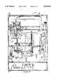
- FIG. 2is a sectional view of the apparatus taken along lines 2--2 of FIG. 1.
- FIG. 3is a sectional view of the apparatus taken along lines 3--3 of FIG. 2.
- FIG. 4is a sectional view of the apparatus taken along lines 4--4 of FIG. 2.
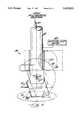
- FIG. 5is a greatly enlarged side view, partially in section, of a portion of the apparatus according to the invention illustrating the build material jet head positioned to have a vertical firing direction.
- FIG. 6is a greatly enlarged side view, partially in section, of a portion of the apparatus according to the invention illustrating the build material jet head positioned to have a near horizontal firing direction based upon rotation about a horizontal axis or flip angle positioning.
- FIG. 7is a schematic side view of the build material jet head as shown in FIGS. 5 and 6 illustrating rotation about a vertical axis, that is, phi angle positioning.
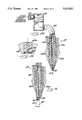
- FIG. 8Ais an enlarged sectional view of the build material jet and connecting conduit according to the invention.
- FIG. 8Bis a greatly enlarged sectional view of the tip portion of the build material jet as shown in FIG. 8A.
- FIG. 9is an enlarged sectional view of another embodiment of a build material jet illustrating a canted tip according to the invention.
- FIG. 10is a schematic sectional view of the build material jet and adjacent wall portion of the article being constructed illustrating a generally vertical build direction.
- FIG. 11is a schematic sectional view of the build material jet and adjacent wall portion of the article being constructed illustrating a build direction along the axis of the jet.
- FIG. 12is a schematic sectional view of the build material jet and adjacent wall portion of the article being constructed illustrating a generally horizontal build direction.
- FIGS. 13A to 13Care schematic plan views of a wall portion of the article being constructed according to the invention.
- FIG. 14is a greatly enlarged sectional view taken along lines 14--14 of FIG. 13C.
- FIGS. 15A to 15Lare schematic perspective view of the article being constructed according to the invention.
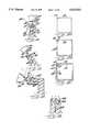
- FIG. 16is a schematic diagram illustrating the build material delivery system according to the invention.
- FIG. 17Ais a side schematic view of the build material jet head and optical test means according to the invention.
- FIG. 17Bis a plan view of the optical test pattern as shown in FIG. 17A.
- FIG. 18is a greatly enlarged section view of the heated conduit connecting the build material reservoir and the build material jet.
- FIG. 19is a perspective view of an article including enhanced target landing point areas in accordance with the present invention.
- FIG. 20is a cross-section view of the article taken along lines 20--20 of FIG. 19.
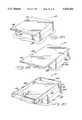
- FIG. 21is a perspective view of an article formed using shadow avoidance according to another aspect of the invention.
- FIG. 22is a cross-section view of the article taken along lines 22--22 of FIG. 21.
- FIGS. 23a and 23bare greatly enlarged cross-sectional views of an upper corner portion of the article shown in FIGS. 21 and 22 and illustrate one embodiment for forming the corner while avoiding shadowing according to another aspect of the invention.
- FIGS. 24a and 24bare greatly enlarged cross-sectional views of an upper corner portion of the article shown in FIGS. 21 and 22 and illustrate a second embodiment for forming the corner while avoiding shadowing according to another aspect of the invention.
- FIGS. 25a and 25bare greatly enlarged cross-sectional views of an upper corner portion of the article shown in FIGS. 21 and 22 and illustrate a third embodiment for forming the corner while avoiding shadowing according to another aspect of the invention.
- the three-dimensional article manufacturing apparatus 30includes a generally rectangular housing 31.
- the housingincludes an access opening 62 closed by a sliding door 63.
- a power port 49facilitates electrical connection to an external power source such as from an AC outlet 65 shown in schematic form.
- a computer port 48allows connection to an external computer 64 also shown in schematic form.
- An external computer 64such as a work station or personal computer, is used to generate a digital data file containing the three-dimensional coordinate data defining an article or model to be built.
- the datamay be from an STL file which defines the article in triangular facets, as would be readily understood by those skilled in the art.
- the data filemay be transferred to the apparatus by a transferable memory medium such as a magnetic disk or tape, or a microelectronic memory, not shown.
- the apparatus 30may be adapted to receive coordinate data from any number of sources having the appropriate electronic data format. If data is transferred by a transferable memory medium, for example, the apparatus 30 may include a disk drive, a tape reader, or other means for reading electronic data from a transferrable memory medium.
- the apparatus 30includes a processor 33 which receives the digital data file and translates the coordinate data therein to control signals, as described further herein.
- the apparatus 30also includes a power supply 29.
- the apparatus 30includes a platform 32 on which the article 37 is built, and a ballistic jetting head 34 (FIGS. 5-7). Droplets of liquid build material are ballistically jetted from a piezoelectric jet 39 carried by jetting head 34 to the platform 32 in order to construct the article 37.
- the build materialis normally solid when at the temperature of the interior of the apparatus.
- the build materialis heated to maintain the build material in a liquid state. Accordingly, heated liquid droplets of build material are jetted from the jetting head 34 to an intended landing position on either the platform 32 or a portion of previously jetted build material. On contact with the platform or previously jetted build material, the heated liquid droplets cool and solidify.
- the piezoelectric jet 39may also be positioned relatively close to the target position so that the build material may, in a sense, not be considered as traveling ballistically. Accordingly, the terms ejected and jetted are also used herein and describe a relatively small gap or no gap.
- the illustrated piezoelectric jet 39is but one embodiment of a dispenser for dispensing build material in metered quantities and to precise target landing positions. It being readily understood by those of skill in the art, that other types of build material dispensers are also contemplated by the invention that can meter build material and accurately deliver it to a target position.
- the term droplet as used hereinis intended to cover individual or discrete volumes of build material that may be ejected, for example, by the piezoelectric jet 39.
- dropletis also intended to cover a volumetrically modulated stream of build material, wherein small quantities or volumes of build material may be connected to adjacent volumes without becoming discrete entities, such as because of a relatively small gap or because of the speed of dispensed build material, for example.
- the apparatus 30includes positioning means for moving the ballistic droplet jetting head 34, including the piezoelectric jet 39 and the thermal normalization means, such as the illustrated heated body 87 in relation to the platform 32.
- Orthogonal drive shaftsfacilitate the movement of the jetting head 34 in the X- and Y-directions relative to the platform 32.
- a pair of X-axis drive shafts 44which are driven by X-axis motor 69 and X-axis drive belt 68, facilitate movement of the jetting head 34 in the X-direction.
- Y-axis drive shaft 45which is driven by Y-axis drive motor 71 and Y-axis drive belt 70 facilitates movement of the ballistic droplet jetting head 34 in the Y-direction.
- movement of the jetting head 34 in the X-Y planar directionmay also be provided by an r/ ⁇ positioner including an arm adapted for radial movement at an angle ⁇ , and a positioner for positioning the jet at a radius, r, along the arm.
- relative movement in the Z-directionis provided by a Z-axis positioner 43 which moves the platform 32 up and down in the Z-direction.
- the Z-axis positionerincludes vertical drive shafts 60 which engage the platform 32.
- the drive shafts 60are driven by the vertical drive motor 61 and vertical drive belts 66 and 67.
- liquid build materialis supplied from a build material reservoir 78 to the jetting head 34 through the build material delivery hose or conduit 72.
- the build material reservoir 78 and the delivery conduit 72both include means for heating the build material so that it remains in a liquid state.
- both the build material reservoir 78 and the delivery conduit 72include an electrical heating element.
- the build material reservoir 78also includes a fill tube 79, and a connection to a pneumatic system for applying either vacuum or pressure to the liquid build material.
- the pneumatic systemincludes a pump 73, an accumulator 74, a pressure regulator 75, a purge valve 76, and a fill valve 77.
- a relatively constant level of liquid build materialis maintained in the build material reservoir 78, so that the surface level of the liquid build material in the build material reservoir 78 is maintained at a relatively constant elevation with respect to the piezoelectric build material jet 39.
- Dashed linesrepresent a nearly full liquid level 99 and a nearly empty liquid level 100 of build material in the build material reservoir 78.
- the jet 39is situated above the surface level of the liquid build material, such as about 1 to 3 inches above the surface level of the liquid build material, to thereby maintain a negative meniscus, that is, having a concave shape at the orifice of the piezoelectric jet 39.
- a vacuumcould be applied to the liquid build material, such as by coupling a vacuum source to the reservoir 78.
- the negative meniscusincreases the accuracy and uniformity of successive ballistically jetted droplets and also reduces undesirable accumulation of build material adjacent the orifice of the jet 39.
- the ballistic droplet jetting head 34includes means for rotating the piezoelectric jet 39 and the heated body 87 about a horizontal axis or to a desired flip angle.
- the axisis defined by a horizontal shaft 85 which is driven by an associated motor 84 through drive gears 57 and 58. Accordingly, the firing direction 41 may be adjusted from vertical, as shown in FIG. 5, to near horizontal as shown in FIG. 6.
- FIGS. 5 and 6also further illustrate the positioning means which rotates the jetting head 34 about a vertical axis on shaft 83 for rotation to a desired phi angle of rotation. This rotation is powered by vertical axis rotation motor 82 shown in schematic form.
- the jetting head 34preferably carries both the piezoelectric jet 39 and the heated body 87. Both of these elements are heated to a temperature above the melting point of the build material. This heat may be generated by an electrical heating element.
- an electrical heatersuch as a resistive wire 120, is operatively connected to the heated body 87. Accordingly, the jet 39 receives heated liquid build material from the delivery hose 72 and maintains the build material in a liquid state prior to jetting.
- the heated body 87is used to periodically normalize surface portions of a partially completed wall.
- Liquid build materialis supplied to the jet 39 through the flexible build material delivery conduit 72.
- the conduit 72is formed into a spiral coil 86 within the vertical shaft 83 to enable rotation of the ballistic droplet jetting head 34 without restricting the flow of build material through the conduit and without requiring a rotatable joint and associated seal.
- FIG. 7illustrates rotation of the ballistic droplet jetting head 34 about the vertical shaft 83.
- the build material delivery conduit 72enters the jetting head through the shaft 83. By rotating the shaft 83, the entire jetting head 34, including the jet 39 and the heated body 87, may be rotated 360 degrees about a vertical axis by the vertical axis motor 82.
- the build materialflows from the conduit 72 through a baffle 88 and a filter 89 to the jet 39, and out of the orifice 40 of the jet as shown in FIG. 8A.
- the heated liquid build material from hose 72enters baffle 88 before passing on to the jet 39.
- the baffle 88provides two 90 degree bends in the path of the flow of build material. Accordingly, acoustic waves generated upstream from the baffle 88 are dissipated as they strike wall 105 of the baffle.
- the baffle 88is beneficial to prevent movement of the head from breaking the negative meniscus at the orifice and also is useful during filling to prevent generation of air bubbles.
- the filter 89prevents any contaminants from clogging the narrow passageway of the jet 39 and also provides a further reduction in the acoustic waves.
- the build materialpasses from the baffle 88 through the tubular connection 106 to the piezoelectric jet 39.
- a build material passage 104 within the piezoelectric jet 39provides fluid communication between the baffle 88 and the orifice 40.
- a heating elementsuch as an electrical resistance wire, may be used to maintain the build material in a liquid state as it passes from the conduit 72 to the baffle 88, tubular connection 106, and jet 39.
- the orifice 40 of the jet 39is maintained at a predetermined elevation above the surface level of liquid build material in the build material reservoir 78 in the illustrated embodiment. Accordingly, a predetermined negative pressure is exerted upon the liquid build material at the orifice 40. As illustrated in FIG. 8B, orifice 40 has a predetermined diameter such that the liquid build material maintains a negative meniscus 103 at the orifice 40 under the influence of the negative pressure. Accordingly, the negative meniscus increases the accuracy and uniformity of successive ballistically jetted droplets and also reduces undesirable accumulation of build material adjacent the orifice 40 of the jet 39.
- the piezoelectric jet 39includes a hollow body 102 including a plastic insert 102a defining a build material flow passage 104, and a containing a piezoelectric element 101, in turn, secured within the body by an epoxy 101a.
- the piezoelectric element 101Upon application of an electric signal to the piezoelectric element 101, the piezoelectric element either contracts or expands depending on the polarity of the signal.
- an acoustic waveis generated in the liquid build material located in the build material flow passage 104. This acoustic wave is transmitted through the liquid build material to the negative meniscus 103 at the orifice 40.
- a droplet of heated liquid build material having a predetermined volumeis jetted or ejected from the orifice 40 in firing direction 41 and at a predetermined velocity.
- the volume and velocity of the dropletare functions of the diameter of the orifice; the size of the piezoelectric element 101; the intensity and polarity of the electrical signal; and the temperature, surface tension and viscosity of the liquid build material.
- the piezoelectric jet 39can be sustained at frequencies of up to 12 KHz. Accordingly, the piezoelectric jet 39 is capable of firing 12,000 droplets per second wherein each droplet has a predetermined volume, velocity and firing direction.
- Other jetting meansare also contemplated by the invention as would be readily understood by those skilled in the art.
- the jet 39may also be operated to jet droplets in relatively quick succession, that is, in bursts of multiple droplets, so that the droplets in each burst collectively coalesce or solidify at an intended landing position as described in copending patent application Ser. No. 08/325,889 and assigned to the present assignee, the entire disclosure of which is incorporated herein by reference.
- the build materialtypically melts at a temperature of from about 50° C. to 250° C., cools quickly and adheres to itself, and has a low rate of shrinkage.
- a build materialpreferably comprises a solution of a resin having a hydroxyl number of from about 5 to 1000, and a molecular weight greater than about 500, dissolved in at least one primary aromatic sulfonamide preferably having a melting point greater than about 25° C.
- the rheology of the build materialis preferably such that a droplet remelts portions of deposited material so as to form a flowable bead.
- hydroxyl numberAs defined by hydroxyl number, through hydrogen bonding, holds together the droplet after jetting through the jetting head.
- the upper limit of hydroxyl numberi.e., 1000 is important in that the higher the hydroxyl number, the higher the heat capacity of the resin, and the resin cools slower. Slower cooling is undesirable in that the build material tends to sag if it cools slowly as the article is being built.
- Exemplary resinsinclude polyester resins, phenolic resins, polyamides, vinyl ester resins, polyurethanes, amino resins, melamine resins, urea resins, epoxy resins, and naturally-derived polymers such as coumarin-indene, shellac, protein and celluosics (e.g., ethyl cellulose, ethyl hydroxy ethyl cellulose, nitro cellulose, etc.), and mixtures thereof.
- Suitable polyester resinsinclude practically any esterification product of a polybasic organic acid and a polyhydric alcohol. Polyester resins can also be derived from the esterification of a polycarboxylic acid or anhydride with a polyhydric alcohol.
- Suitable phenolic resinsinclude practically any reaction product of an aromatic alcohol with an aldehyde. Particularly preferred, are the phenolic resins prepared by the reaction of phenol with formaldehyde.
- Suitable vinyl ester resinsinclude practically any reaction product of an unsaturated polycarboxylic acid or anhydride with an epoxy resin.
- Exemplary epoxiesinclude virtually any reaction product of a polyfunctional halohydrin, such as epichlorohydrin, with a phenol or polyhydric phenol.
- the build materialincludes about 1 to 50 percent of the resin, preferably about 5 to 30 percent, and more preferably about 5 to 15 percent, by weight of the resin.
- Suitable aromatic sulfonamidesare preferably primary C 1 to C 15 benzenesulfonamides, and most preferably the substitution is alkyl and is at the para position.
- Exemplary primary aromatic sulfonamidesinclude p-n-ethylbenzenesulfonamide, p-toluenesulfonamide, p-methoxybenzenesulfonamide, p-n-nonylbenzenesulfonamide, p-n-butylbenzenesulfonamide, and mixtures thereof.
- the build materialincludes about 1 to 50 percent, preferably about 70 to 90 percent, and more preferably about 75 to 90 percent by weight of one or more of the aromatic sulfonamides. Particularly preferred is a 50/50 mixture of p-toluenesulfonamide and p-n-ethylbenzenesulfonamide.
- the build materialcan include antioxidants (e.g., Ultranox 626 available from Borg Warner Chemicals, Inc.), flexibilizers, magnetic particles, pigments, and fluorescent agents, and other additives, the addition of which is within the skill of one in the art. Dyes can be added to the build material. Suitable dyes include FD & C Blue #1, Neozapon Red 492, Savinyl Black RLS and the like. Another additive could be a secondarily reactive organic compound such as one activated by exposure to UV light. These compounds can be used to provide an article which can be hardened so as to be unmeltable or machinable. Typically, the build material includes from about 1 to 10 percent by weight of the various additives.
- Suitable build materialsare further described in commonly assigned copending U.S. patent application Ser. No. 08/325,694, the entire disclosure of which is incorporated herein by reference.
- other techniques for jetting or ejecting build materialare further described in commonly assigned copending patent application Ser. No. 08/326,015.
- FIG. 9An alternative embodiment of a jet 39' is shown in FIG. 9 having a firing direction 41' oriented at an offset angle ⁇ relative to the jet axis 107 defined by the cylindrical body 102'. This orientation is obtained by providing a tip 108 which is curved or canted at the angle offset from the body.
- the other elementsare indicated by prime notation and are similar to those elements described in the first embodiment.
- This second embodimenthas the advantage of allowing the firing direction 41' to be close to horizontal without interference with a layer of the article being constructed.
- the wider body 102 portion of the jet 39 containing the piezoelectric element 101might otherwise come into contact with previously jetted layers of build material.
- the angle ⁇is not less than 5° or more preferably not less than 20° as illustrated.
- FIGS. 10, 11 and 12there are illustrated the formation of walls of an article oriented at various angles.
- a cross-section of a wallis schematically illustrated and the wall is 3 droplets thick, it being understood that the burst mode of operation may also be used in the present invention as described above in which case the wall is three bursts thick.
- the 3 droplet wall thicknessprovides a balance of strength, stability, and conservation of time and material.
- a vertical wallis being formed and the piezoelectric jet 39 is positioned directly above the wall.
- a heated liquid droplet of build material 35is jetted from the orifice 40 in the firing direction 41.
- the liquid droplet 35will contact the wall at the intended landing point 36. Upon contact, the liquid droplet will bond with the previously solidified wall portion. Because the wall is 3 droplets wide, 3 droplets will be required to form a horizontal layer of the wall.
- Previously jetted pass or layer 38is indicated by dashed lines schematically representing the droplets which formed the previous layer. In this illustration, the firing direction 41 and the build direction 42 are aligned.
- the jet 39may be accurately positioned and aligned with an intended landing point 36, the firing direction and build direction need not be aligned. Moreover, because of the adherence of the build material, it is possible to build walls having a build direction 42' as much as 45°, and more preferably 25° from vertical while maintaining the jet 39' and firing direction 41' in a vertical orientation as illustrated by the dashed lines of FIG. 10.
- FIG. 11illustrates the formation of a wall having a non-vertical build direction wherein the build direction 42 and the axis of the jet 39, that is, its firing direction 41 are aligned.
- This arrangementmay be preferred in the construction of walls having build directions 42 which are in the range of from vertical down to about 5° from horizontal.
- FIG. 12illustrates the formation of walls having a build direction 42 in the range of horizontal to about 45° from horizontal. It is not desirable to bring the firing direction 41 of the jet 39 below 5° and, more preferably 20°, from horizontal because the jet would contact previously jetted portions of the article. Accordingly, for horizontal walls, it is preferable to fire the piezoelectric jet 39 at orientations such that the firing direction 41 is at least 5°, and more preferably 20°, from horizontal as may be readily achieved with the embodiments of the jet 39 according to the invention. Accordingly, with the build material jet 39 and jetting head 34 positionable in five degrees of freedom, horizontal walls can be produced without the need for separate support material. In certain article geometries, struts may be formed which can be later removed from the article as would be readily understood by those skilled in the art.
- FIGS. 13A-13Cthere is illustrated a preferred order of firing droplets of build material so as to minimize irregularities in the formation of a layer or pass on a wall.
- a first linear segment or wall portionis formed by advancing the build material delivery jet along the first path 50 in a first direction 51. As the jet is advanced, ballistic droplets of build material are jetted to form the first segment on top of the existing wall.
- the build material delivery jetis then advanced along a second path 52 to construct a second segment side-by-side with the first segment and in a second direction 53 opposite the first direction 51.
- the jetis advanced along a third path 54 side-by-side with the second path 52 in a direction 55 opposite the second direction 53. Accordingly, a third segment is formed side-by-side with the second segment.
- linear segmentsare illustrated, arcuate or curved segments may also be similarly formed according to the invention.
- FIG. 14illustrates another aspect of the invention for enhancing build uniformity and accuracy in the article.
- the respective segments 56bare laid down in an opposite order from the underlying segments 56a.
- irregularitiesmay occur at the beginning and end of the segment.
- the beginning of the segmentmay be relatively thick while the end may be relatively narrow. These differences in thickness may result from the acceleration and deceleration of the jet as it starts and stops movement or from surface tension effects of the build material. By altering the direction of advancement of the jet when forming side-by-side segments, these irregularities may be significantly reduced.
- FIGS. 15A-Lthere is illustrated the formation of a three-dimensional article 37' having unsupported features.
- liquid build materialis first jetted from the piezoelectric jet 39 to the platform 32 and then to previously jetted build material thereby forming successive layers.
- a release structure 109may first be constructed to facilitate removal of the finished article from the platform 32.
- This structure 109comprises a plurality of walls which have reduced thickness in the illustrated embodiment.
- perforated wall portionsmay be formed, or a reduced number of contact points or piers may be formed supporting the article, for example, as would be readily appreciated by those skilled in the art.
- the release structure 109also provides a starting structure upon which the three-dimensional article can be built and which is strong enough to provide a stable support during the construction of the article. As shown, the jet 39 moves along path 117 with a vertical firing direction 41 pointed straight down towards the partially constructed release structure 109. In a preferred embodiment, each successive pass or layer is jetted as the jet moves in an opposite direction.
- FIG. 15Billustrates the formation of a horizontal wall 110 which will form the bottom surface of the article.
- the horizontal wall 110 in this embodimenthas a horizontal build direction and a three droplet or three segment thickness.
- Each linear segmentis jetted as the jet 39 advances along a path 117 parallel to the edge of the wall with the firing direction 41 oriented at an angle of about 20 degrees from horizontal.
- each segmentmay be jetted as the jet moves in a direction opposite to the direction from which adjacent segments were jetted.
- FIG. 15Cthe completed horizontal wall 110 extends across the top of the release structure 109.
- the dotted linesindicate the extent of the horizontal wall.
- vertical walls 111may be formed upon the horizontal wall 110. These vertical walls 111, which are part of the model or article 37' being constructed, are three droplets or segments thick in the illustrated embodiment. This thickness for the structural parts of the article adds strength and stability to the finished article.
- An internal hatched wall pattern 112provides added structural stability and strength to a base portion of the article.
- the hatchingif desired, may also be extended throughout the interior of the article being formed, thereby adding to the overall strength and stability of the article. To increase overall speed, the hatching may preferably be provided only in the base portion.
- the hatched wall pattern 112may be made to any desired thickness.
- the hatched wall pattern 112may be formed at the same vertical rate as the vertical walls 111. Accordingly, a pass or layer may be completed for the vertical walls 111 and the hatched wall pattern 112 before moving on to the next layer for the vertical walls or hatched wall pattern.
- FIG. 15Eillustrates build rate normalization using a heated body 87.
- the heated body or ironing pin 87may be carried by the jetting head 34. Accordingly, after a predetermined number of passes or layers have been jetted, there may be a need to normalize the outer surface portions of the vertical walls. In a preferred embodiment, the process of build rate normalization occurs after 21 passes or layers of build material have been jetted. Accordingly, a balance is struck between the need for normalization and the time spent performing the operation.
- the heated body 87may comprise aluminum with a Teflon® release coating thereon.
- the heated body 87is brought into contact with the upper surface of walls 111 and advanced in a path 118 parallel to the outer surface.
- the path 118is reversed each time the structure is normalized.
- the heated body 87causes the build material to melt or reflow. Normalization may not be required for hidden internal structures, such as the hatched pattern of walls for strengthening the base portion of the article.
- the thermal normalizationis further described in copending application Ser. No. 08/326,009 and assigned to the assignee of the present invention, the entire disclosure of which is incorporated herein by reference.
- FIG. 15Fillustrates the continued building of vertical walls 111.
- FIG. 15Falso illustrates the formation of a hatched structure 112 which fills only the bottom portion of the article.
- FIG. 15Ga second horizontal wall 113 is being built over vertical walls 111.
- This structureis built using the same techniques described with regard to FIG. 15E.
- FIG. 15Hthere is illustrated the extension of wall 113 beyond vertical walls 111, creating a cantilevered or unsupported horizontal wall portion 114.
- This unsupported wall portion 114is created in the same manner as the previously formed supported portions.
- the jet 39continues jetting passes or layers of build material on previous passes or layers. As before, the firing direction 41 is oriented at an angle near horizontal.
- FIG. 15Iillustrates the completion of horizontal wall 113 with the unsupported wall portion 114.
- FIG. 15Jvertical walls 115 are being formed on horizontal wall 113 including unsupported horizontal portion 114.
- Vertical walls 115are formed using the same sequence of operations discussed with regard to vertical walls 111 in FIGS. 15D-F.
- FIG. 15Kvertical walls 115 have been completed, and the formation of horizontal wall 116 on vertical walls 115 is shown. The formation of this horizontal wall follows the same sequence as discussed with regard to horizontal walls 113 and 110.
- FIG. 15Lhorizontal wall 116 is complete, thereby completing this portion of the article 37'.
- a preferred embodiment of the present inventionis capable of forming complex models having unsupported horizontal or cantilevered structures without the need for a surrounding support material.
- the completed modelmay be removed from the platform 32 by breaking the release structure 109.
- the release structure 109breaks away relatively easily from both the platform 32 and the horizontal wall 110 forming the bottom of the model. Accordingly, the present invention provides a relatively simple and inexpensive way to produce a three-dimensional model or article of high accuracy.
- FIG. 16illustrates the vacuum system used to empty and fill the delivery conduit 72 and jet 39.
- the vacuum systemapplies either a vacuum or a pressure to the build material reservoir 78 to either empty or fill the delivery hose 72, jetting head 34, and jet 39.
- fill valve 77is closed and purge valve 76 is opened.
- pump 73applies a vacuum through purge valve 76 to the build material reservoir 78.
- build material in the conduit 72 and jet 39is drawn back into the build material reservoir 78.
- This processallows the heaters in the jetting head 34 and conduit 72 to be turned off without having build material solidify in either the conduit or the jet.
- the build material reservoir 78may then be cooled, allowing the build material therein to solidify without harm.
- the purge valve 76is closed and the fill valve 77 is opened.
- the pump 73is then used to create a positive pressure in the accumulator bottle 74.
- Pressure regulator 75is used to regulate the pressure that is applied to the build material reservoir 78 through the fill valve 77.
- the slowing increasing velocity of the material through the hose 72causes the leading edge of the build material to form a positive meniscus as it passes through the conduit.
- This positive or convex meniscusprevents the formation of bubbles in the conduit or jet which could interfere with operation of the piezoelectric jet.
- the pressure waveformthen cuts off abruptly, allowing the formation of a negative meniscus at the orifice of the piezoelectric jet without causing an accumulation of build material adjacent the orifice.
- the operation of the pump 73, fill valve 77, purge valve 76, and pressure regulator 75are controlled by the processor 33. Accordingly, emptying and filling operations may occur automatically in response to the power up and power down of the system.
- the processormay also determine whether the system is properly powered down or improperly shut off due to a power failure. If the system is properly shut down, the processor will send control signals to empty the conduit and jet. If there is a power failure, normal emptying may not be performed and build material may solidify in the jet and conduit. The processor then initiates emptying and filling prior to permitting normal operation of the jet.
- FIG. 17Athere is illustrated a jetting head 34 having a heated body or ironing pin 87, a piezoelectric jet 39, and an optical detection unit 90.
- the optical detection unit 90includes a light emitting diode (LED) 91 and an optical receiver 92.
- the LED 91emits a beam 98 of light directed down to the surface being inspected. If the surface has certain reflective characteristics, the beam reflects back up toward the optical receiver 92.
- the LED 91 and receiver 92are mounted such that the receiver detects the reflected light from a reflective surface.
- the solidified build materialhas predetermined reflective characteristics such that the beam 98 may detect its presence.
- the piezoelectric jetmay jet a predetermined two-dimensional pattern 121 on the platform 32 of the system as illustrated in FIG. 17B.
- the optical detection unit 90then scans the pattern 121 to determine the X- and Y-coordinates of each feature on the pattern.
- the measured coordinatescan be compared to the known positions of the jet 39 when jetting the pattern and an analysis of the comparison used to determine X- and Y-axis offsets, for example.
- the jet 39may also be used to jet a test pattern having a vertical component so that build rate may be determined or a Z-axis offset determined.
- the optical detection unit 90may be used to restart the build process in the event that the creation of the article is halted before completion. In this embodiment, the optical detection unit is used to determine the status of the build process at the time of the interruption.
- the optical detection unit 90represents an embodiment of test and compensation means for permitting adjustment of a control parameter, such as firing frequency or carriage speed, as would be readily understood by those skilled in the art.
- a control parametersuch as firing frequency or carriage speed
- mechanical, electrical or acoustical sensing meanscould be used to examine a test pattern and, hence, provide the test and compensation means according to the invention.
- FIG. 18illustrates a cross-section of the build material conduit 72 which includes a flexible interior tubing 93, formed of a durable material such as VitronTM.
- the interioris surrounded by a thermally conductive material layer, such as a wire mesh braid 94.
- the conductive materialis a copper braid.
- An insulated electrically resistive wire heating element 95is wrapped around the wire mesh braid 94 in a spiral fashion.
- the resistive wiremay comprise a nichrome wire surrounded by an insulating material.
- the conduit 72is thus uniformly heated by passing a current through the resistive wire.
- the braided layer 94 and resistive wire heating element 95are surrounded by an insulating material layer 96, such as fiberglass.
- the complete structureis then encased in heat-shrink tubing 97. In a preferred embodiment, this predetermined temperature is greater than the melting point of the build material. Accordingly, build material within the conduit 72 can be maintained as a liquid.
- the processorwhich is operatively connected to dispensing means for constructing the article based upon the article defining data, preferably includes target landing point enhancing means.
- the target landing point enhancing meansoperates the dispensing means to construct an enlarged surface of a first article portion to thereby define an enhanced target landing point area for ejected droplets of build material for constructing a second article portion adjacent the first article portion.
- the dispensing meansis preferably a jet 39 as shown in the illustrated embodiment, although other dispensers are also contemplated by the present invention.
- the enlarged or enhanced target landing point areas 135are shown greatly exaggerated in size in FIGS. 19 and 20 for greater ease of understanding. More particularly, the illustrated article 130 includes a square bottom 131 formed by four vertically extending walls. A pair of horizontal walls 132 extend outwardly from opposite upper sides of the bottom 131. These horizontal walls include enhanced target landing point areas 135 integrally formed on the outer side edges of the horizontal walls 132 as further shown by the dotted lines of FIG. 20.
- the enhanced target landing point areas 135permit a slight misalignment or error that may occur between adjacent article portions--in the illustrated embodiment, between the horizontal walls 132 and the vertical rectangular article portion 133 positioned thereon. If a misalignment or error occurred without the enhanced target landing point areas 135 of the present invention, ejected droplets of build material intended to form the rectangular article portion 133 may miss their intended target positions. Accordingly, an opening or gap 138 (illustrated in dotted lines) may be formed in the rectangular article portion 133 and leave an accumulation of build material 139 (also illustrated in dotted lines) in an undesired position.
- the target landing point enhancing meanspreferably comprises enhancement determining means for determining placement of the enhanced target landing point area based upon the article defining data and also preferably based upon a change in a firing direction for the jet 39 (FIG. 19) as needed to construct the rectangular article portion 133 on the horizontal walls 132 in the illustrated embodiment.
- the target landing point enhancing meansalso preferably includes means for constructing the enhanced target landing point area 135 at a same jet firing direction as for constructing an adjacent surface of the first article portion.
- the horizontal walls 132define planar surfaces adjacent the rectangular article portion 133 and, accordingly, the target landing point enhancing means includes means for enlarging the planar surface of the horizontal walls along respective planes defined by the planar surfaces. Enlarged surfaces may also be formed that are not generally aligned with a plane defined by the adjacent article portion as would be readily understood by those skilled in the art.
- the processorpreferably includes means for forming the each article portion having a predetermined wall thickness.
- the target landing point enhancing meanspreferably includes means for operating the jet 39 to construct the enlarged surface of a first article portion in a range of about 10 to 50 percent of the predetermined wall thickness of the second article portion. Accordingly, for a wall thickness of about 0.021 inches, the enhanced target landing point areas 135 may be relatively small and in the range of about 0.001 to 0.010 inches. Accordingly, the overall appearance of the article 130 is not adversely affected by the target landing point enhancing means of the present invention.
- the target landing point enhancing meansmay be used for many different configurations of adjacent article portions, particularly where a change in firing direction of the jet is desired.
- the processorpreferably further includes shadow avoiding means for operating the jet 39 to construct adjacent article portions so that a jet firing path for constructing one article portion is unobstructed by a previously constructed part of another article portion.
- the ramp 140includes a lower release portion 141 and a horizontal bottom wall 142 connected thereto. Front and rear generally vertically extending walls are defined by additional portions of the ramp 140 as illustrated. A pair of intersecting generally planar walls 145, 146 extend upward to form the upper portion of the ramp 140. The front wall 145 is inclined at an angle of about 20° from vertical and the back wall 146 is inclined at about 70° from vertical in the illustrated embodiment. A pair of opposing side walls 148 close the sides of the ramp 140.
- the shadow avoiding meanspreferably comprises sequencing means for constructing a part of the first article portion to a predetermined extent, for then completing construction of the second article portion, and for then completing construction of the remaining part of the first portion.
- a part of the front wall 145is constructed with a firing direction aligned with the firing direction of the build material jet 39 to a predetermined extent that will not obstruct construction of the back wall 146.
- construction thereofis stopped short, such as to account for a predetermined overbuild of several percent which may be desirable to prevent voids in the article.
- the remainder 147 of the ramp 140may be built along the jet firing direction and the aligned build direction for the back wall 146.
- the remaining part of the back wall 146is constructed along with the remaining part of the front wall 145.
- the apparatus 30preferably includes normalization means for normalizing a predetermined part of the article during construction thereof as described above.
- the normalization meansperiodically ensures that the dimensions of the article are accurate relative to a predetermined coordinate system.
- the shadow compensation meansmay include normalization control means for operating the normalization means to displace an overbuilt part of the front wall that would otherwise block or obstruct a jet firing path for constructing the back wall.
- the normalization meansis preferably thermal normalization means provided by a heated body 87 carried and positioned by the jet positioning means of the dispensing head 34. After removing the overbuilt part of the front wall 145 using the heated body 87, the ramp 140 may be completed by positioning the jet 39 to complete the back wall and front wall as shown in FIG. 23b.
- a third variation of shadow avoidanceis illustrated with additional reference to FIGS. 25a and 25b.
- the front and back walls 145, 146are constructed from respective first and second jet firing directions 145a, 146a.
- the shadow avoiding means in this variation or embodimentcomprises jet firing direction control means for forming an intersection 148 between the front and back walls by orienting the jet 39 to have a jet firing direction between the first and second jet firing directions 145a, 146a.
- the illustrated variations of the shadow avoidance meansmay be used independently or combined with each other.
- a combination of controlling the build sequencemay be desirably used with the thermal normalization control to remove obstructing or shadowing portions of the article.
- the shadow avoidance embodimentsmay be used independently or combined with the enhanced target landing point areas as also described herein. Accordingly, a highly accurate finished three-dimensional article may be produced according to the invention.
- a first embodiment of a method for making a three-dimensional article based upon article defining datapreferably includes the steps of: dispensing a plurality of droplets of build material from a build material dispenser and toward target landing points; and constructing the article based upon the article defining data by operating the dispenser to construct an enlarged surface of a first article portion defining an enhanced target landing point area and operating the dispenser to construct a second article portion adjacent the first article portion.
- the step of constructing the articlepreferably comprises the step of advancing the dispenser along a predetermined path of travel relative to a platform in three directions and relatively rotatably positioning the dispenser about two axes thereby defining five degrees of freedom of movement for the dispenser relative to the platform.
- another method aspect of the present inventionis for making a three-dimensional article based upon article defining data, and while avoiding shadowing. More particularly, the method preferably includes the steps of: dispensing a plurality of droplets of build material from a build material dispenser and toward target landing points; and constructing the article based upon the article defining data by operating the dispenser to construct first and second adjacent article portions so that a dispensing path for constructing the first article portion is unobstructed by a previously constructed part of the second article portion to thereby avoid shadowing of construction of the first article portion by a previously constructed part of the second article portion.
Landscapes
- Engineering & Computer Science (AREA)
- Chemical & Material Sciences (AREA)
- Materials Engineering (AREA)
- Mechanical Engineering (AREA)
- Physics & Mathematics (AREA)
- Manufacturing & Machinery (AREA)
- Optics & Photonics (AREA)
- Coating Apparatus (AREA)
Abstract
Description
Claims (31)
Priority Applications (3)
| Application Number | Priority Date | Filing Date | Title |
|---|---|---|---|
| US08/326,004US5633021A (en) | 1994-10-19 | 1994-10-19 | Apparatus for making a three-dimensional article |
| AU39496/95AAU3949695A (en) | 1994-10-19 | 1995-10-18 | Apparatus and methods for making a three-dimensional article |
| PCT/US1995/012866WO1996012608A2 (en) | 1994-10-19 | 1995-10-18 | Apparatus and methods for making a three-dimensional article |
Applications Claiming Priority (1)
| Application Number | Priority Date | Filing Date | Title |
|---|---|---|---|
| US08/326,004US5633021A (en) | 1994-10-19 | 1994-10-19 | Apparatus for making a three-dimensional article |
Publications (1)
| Publication Number | Publication Date |
|---|---|
| US5633021Atrue US5633021A (en) | 1997-05-27 |
Family
ID=23270409
Family Applications (1)
| Application Number | Title | Priority Date | Filing Date |
|---|---|---|---|
| US08/326,004Expired - Fee RelatedUS5633021A (en) | 1994-10-19 | 1994-10-19 | Apparatus for making a three-dimensional article |
Country Status (3)
| Country | Link |
|---|---|
| US (1) | US5633021A (en) |
| AU (1) | AU3949695A (en) |
| WO (1) | WO1996012608A2 (en) |
Cited By (68)
| Publication number | Priority date | Publication date | Assignee | Title |
|---|---|---|---|---|
| US5968561A (en)* | 1998-01-26 | 1999-10-19 | Stratasys, Inc. | High performance rapid prototyping system |
| US6471992B1 (en) | 1997-02-20 | 2002-10-29 | Therics, Inc. | Dosage form exhibiting rapid disperse properties, methods of use and process for the manufacture of same |
| US6578596B1 (en) | 2000-04-18 | 2003-06-17 | Stratasys, Inc. | Apparatus and method for thermoplastic extrusion |
| US6612824B2 (en)* | 1999-03-29 | 2003-09-02 | Minolta Co., Ltd. | Three-dimensional object molding apparatus |
| US20040005374A1 (en)* | 2002-05-16 | 2004-01-08 | Subhash Narang | Creating objects through X and Z movement of print heads |
| US6682684B1 (en) | 2000-09-07 | 2004-01-27 | Honeywell International Inc. | Procedures for rapid build and improved surface characteristics in layered manufacture |
| US6697694B2 (en) | 1998-08-26 | 2004-02-24 | Electronic Materials, L.L.C. | Apparatus and method for creating flexible circuits |
| US20040062814A1 (en)* | 1997-02-20 | 2004-04-01 | Therics, Inc. | Method and materials for controlling migration of binder liquid in a powder |
| US20040148040A1 (en)* | 2003-01-16 | 2004-07-29 | Kia Silverbrook | Method for creating a 3-d object |
| US6823230B1 (en) | 2000-09-07 | 2004-11-23 | Honeywell International Inc. | Tool path planning process for component by layered manufacture |
| US20050252631A1 (en)* | 2003-02-03 | 2005-11-17 | Rapid Ceramic Technologies Ltd | Ceramic article and method of manufacture therefor |
| US20070003656A1 (en)* | 2005-07-01 | 2007-01-04 | Stratasys, Inc. | Rapid prototyping system with controlled material feedstock |
| US20070119826A1 (en)* | 2005-11-30 | 2007-05-31 | Honeywell International, Inc. | Ion fusion formation process including precise heat input and temperature control |
| US20070148006A1 (en)* | 2005-11-04 | 2007-06-28 | University Of Southern California | Material Delivery System Using Decoupling Accumulator |
| US7261542B2 (en) | 2004-03-18 | 2007-08-28 | Desktop Factory, Inc. | Apparatus for three dimensional printing using image layers |
| US20070228590A1 (en)* | 2006-04-03 | 2007-10-04 | Stratasys, Inc. | Single-motor extrusion head having multiple extrusion lines |
| US7332537B2 (en) | 1996-09-04 | 2008-02-19 | Z Corporation | Three dimensional printing material system and method |
| US20080192104A1 (en)* | 2007-02-13 | 2008-08-14 | 2Bot Corporation | Systems and methods for providing a personal affector machine |
| US20080213419A1 (en)* | 2007-02-12 | 2008-09-04 | Stratasys, Inc. | Viscosity pump for extrusion-based deposition systems |
| US20090035405A1 (en)* | 2007-07-31 | 2009-02-05 | Stratasys, Inc. | Extrusion head for use in extrusion-based layered deposition modeling |
| US7550518B2 (en) | 2000-04-14 | 2009-06-23 | Z Corporation | Methods and compositions for three-dimensional printing of solid objects |
| US7569273B2 (en) | 2003-05-21 | 2009-08-04 | Z Corporation | Thermoplastic powder material system for appearance models from 3D printing systems |
| US20100021580A1 (en)* | 2008-07-25 | 2010-01-28 | Swanson William J | Pantograph assembly for digital manufacturing system |
| US20100031882A1 (en)* | 2008-08-05 | 2010-02-11 | Panasonic Electric Works Co., Ltd. | Apparatus for producing a laminated object |
| US20100136340A1 (en)* | 2003-01-21 | 2010-06-03 | University Of Southern California | Dry material transport and extrusion |
| US7795349B2 (en) | 1999-11-05 | 2010-09-14 | Z Corporation | Material systems and methods of three-dimensional printing |
| US20100271608A1 (en)* | 2008-12-31 | 2010-10-28 | Max Eric Schlienger | System and method for imaging apparatus calibration |
| US20110049767A1 (en)* | 2009-08-09 | 2011-03-03 | Max Eric Schlienger | System, apparatus, and method for resin level maintenance in a stereo-lithography device |
| US7905951B2 (en) | 2006-12-08 | 2011-03-15 | Z Corporation | Three dimensional printing material system and method using peroxide cure |
| US20110076350A1 (en)* | 2005-11-04 | 2011-03-31 | University Of Southern California | Extrusion of cementitious material with different curing rates |
| US7968626B2 (en) | 2007-02-22 | 2011-06-28 | Z Corporation | Three dimensional printing material system and method using plasticizer-assisted sintering |
| US8167999B2 (en) | 2007-01-10 | 2012-05-01 | 3D Systems, Inc. | Three-dimensional printing material system with improved color, article performance, and ease of use |
| US20120189729A1 (en)* | 2011-01-20 | 2012-07-26 | Pax Charles E | Multi-extruder |
| US8827684B1 (en)* | 2013-12-23 | 2014-09-09 | Radiant Fabrication | 3D printer and printhead unit with multiple filaments |
| US20140363532A1 (en)* | 2013-06-10 | 2014-12-11 | Kirk W. Wolfgram | Multiple color extrusion type three dimensional printer |
| US8944802B2 (en) | 2013-01-25 | 2015-02-03 | Radiant Fabrication, Inc. | Fixed printhead fused filament fabrication printer and method |
| US20150197063A1 (en)* | 2014-01-12 | 2015-07-16 | Zohar SHINAR | Device, method, and system of three-dimensional printing |
| WO2016192680A1 (en) | 2015-06-03 | 2016-12-08 | Triastek, Inc. | Dosage forms and use thereof |
| WO2017062600A1 (en) | 2015-10-06 | 2017-04-13 | University Of South Florida | High-throughput platform for bioprinting tissue modules |
| US9912001B2 (en)* | 2013-08-07 | 2018-03-06 | Massachusetts Institute Of Technology | Extruder feed system |
| US20180126640A1 (en)* | 2016-11-04 | 2018-05-10 | Cc3D Llc | Additive manufacturing system having multi-flex nozzle |
| US10350822B1 (en) | 2018-01-09 | 2019-07-16 | Triastek Inc. | Dosage forms with desired release profiles and methods of designing and making thereof |
| US10427352B2 (en)* | 2013-08-06 | 2019-10-01 | Airbus Operations Limited | Extrusion-based additive manufacturing system and method |
| US20200016834A1 (en)* | 2018-07-12 | 2020-01-16 | Seiko Epson Corporation | Three-dimensional forming apparatus and method of forming three-dimensional object |
| US20200016833A1 (en)* | 2018-07-12 | 2020-01-16 | Seiko Epson Corporation | Three-dimensional forming apparatus and method of forming three-dimensional object |
| JP2020006625A (en)* | 2018-07-11 | 2020-01-16 | セイコーエプソン株式会社 | 3D modeling device and nozzle unit |
| US10675813B2 (en)* | 2014-11-26 | 2020-06-09 | Homag Bohrsysteme Gmbh | Device for forming 3D bodies |
| US20200207017A1 (en)* | 2018-12-27 | 2020-07-02 | Seiko Epson Corporation | Three-dimensional shaping apparatus |
| US11001001B2 (en)* | 2018-12-21 | 2021-05-11 | Seiko Epson Corporation | Three-dimensional shaping apparatus and three-dimensional shaped article production method |
| US11014298B2 (en)* | 2018-11-22 | 2021-05-25 | Seiko Epson Corporation | Three-dimensional shaping apparatus and control method for three-dimensional shaping apparatus |
| US11020901B2 (en)* | 2018-11-29 | 2021-06-01 | Seiko Epson Corporation | Three-dimensional shaping apparatus and method of controlling three-dimensional shaping apparatus |
| US11241829B2 (en)* | 2019-10-11 | 2022-02-08 | Ingersoll Machine Tools, Inc. | Orientable nozzle for additive manufacturing |
| US11292071B2 (en)* | 2017-11-15 | 2022-04-05 | Kobe Steel, Ltd. | Method for producing molded article, production device, and molded article |
| EP3981392A1 (en) | 2016-05-05 | 2022-04-13 | Triastek, Inc. | Controlled release dosage form |
| WO2022089588A1 (en) | 2020-10-30 | 2022-05-05 | 南京三迭纪医药科技有限公司 | Gastroretentive pharmaceutical dosage form |
| US20220203620A1 (en)* | 2020-12-24 | 2022-06-30 | Seiko Epson Corporation | Three-dimensional shaping apparatus and three-dimensional shaped article production method |
| US11478979B2 (en)* | 2018-12-05 | 2022-10-25 | Xerox Corporation | Apparatus and method for variable magnetic alignment in fused deposition modeling (FDM) magnets |
| US11478982B2 (en)* | 2018-06-25 | 2022-10-25 | Kj Chemicals Corporation | Three-dimensional molding apparatus and three-dimensional molding method using different types of materials |
| US11571391B2 (en) | 2018-01-09 | 2023-02-07 | Triastek, Inc. | Oral drug dosage forms compromising a fixed-dose of an ADHD non-stimulant and an ADHD stimulant |
| US11685113B2 (en) | 2017-03-06 | 2023-06-27 | Katholieke Universiteit Leuven | 3D printing of porous liquid handling device |
| US11787111B2 (en) | 2017-08-24 | 2023-10-17 | Seiko Epson Corporation | Shaping material supply device and three-dimensional shaping apparatus |
| US11833717B2 (en) | 2020-06-26 | 2023-12-05 | Seiko Epson Corporation | Three-dimensional shaping device |
| US11850801B2 (en) | 2018-11-28 | 2023-12-26 | Seiko Epson Corporation | Three-dimensional shaping apparatus and method of manufacturing three-dimensional shaping object |
| US20240001610A1 (en)* | 2020-12-03 | 2024-01-04 | Mark One S.R.L. | An extruding device for making three-dimensional objects |
| US12102721B2 (en) | 2017-01-26 | 2024-10-01 | Triastek, Inc. | Dosage forms of controlled release at specific gastrointestinal sites |
| US20240351271A1 (en)* | 2013-11-19 | 2024-10-24 | Guill Tool & Engineering Co., Inc. | Coextruded, multilayer and multicomponent 3d printing inputs |
| US12162210B2 (en) | 2020-07-28 | 2024-12-10 | Seiko Epson Corporation | Three-dimensional shaping device and method for manufacturing three-dimensional shaped object |
| US12220859B2 (en) | 2019-06-28 | 2025-02-11 | Seiko Epson Corporation | Three-dimensional shaping device and method for manufacturing three-dimensional shaped object |
Families Citing this family (15)
| Publication number | Priority date | Publication date | Assignee | Title |
|---|---|---|---|---|
| DE19515165C2 (en)* | 1995-04-25 | 1997-03-06 | Eos Electro Optical Syst | Device for producing an object using stereolithography |
| US6103176A (en)* | 1997-08-29 | 2000-08-15 | 3D Systems, Inc. | Stereolithographic method and apparatus for production of three dimensional objects using recoating parameters for groups of layers |
| US6622062B1 (en) | 1999-01-19 | 2003-09-16 | 3D Systems, Inc. | Method and apparatus for forming three-dimensional objects using line width compensation with small features retention |
| US6261077B1 (en) | 1999-02-08 | 2001-07-17 | 3D Systems, Inc. | Rapid prototyping apparatus with enhanced thermal and/or vibrational stability for production of three dimensional objects |
| US6241934B1 (en) | 1999-02-08 | 2001-06-05 | 3D Systems, Inc. | Stereolithographic method and apparatus with enhanced control of prescribed stimulation production and application |
| US6132667A (en)* | 1999-02-08 | 2000-10-17 | 3D Systems, Inc. | Stereolithographic method and apparatus with enhanced control of prescribed stimulation production and application |
| US6129884A (en)* | 1999-02-08 | 2000-10-10 | 3D Systems, Inc. | Stereolithographic method and apparatus with enhanced control of prescribed stimulation production and application |
| US6406658B1 (en) | 1999-02-08 | 2002-06-18 | 3D Systems, Inc. | Stereolithographic method and apparatus for production of three dimensional objects using multiple beams of different diameters |
| US6126884A (en)* | 1999-02-08 | 2000-10-03 | 3D Systems, Inc. | Stereolithographic method and apparatus with enhanced control of prescribed stimulation production and application |
| US6399010B1 (en) | 1999-02-08 | 2002-06-04 | 3D Systems, Inc. | Method and apparatus for stereolithographically forming three dimensional objects with reduced distortion |
| US6325961B1 (en) | 1999-02-08 | 2001-12-04 | 3D Systems, Inc. | Stereolithographic method and apparatus with enhanced control of prescribed stimulation and application |
| US6159411A (en)* | 1999-02-08 | 2000-12-12 | 3D Systems, Inc. | Rapid prototyping method and apparatus with simplified build preparation for production of three dimensional objects |
| US6162378A (en)* | 1999-02-25 | 2000-12-19 | 3D Systems, Inc. | Method and apparatus for variably controlling the temperature in a selective deposition modeling environment |
| US10307957B2 (en)* | 2015-03-10 | 2019-06-04 | Siemens Product Lifecycle Management Software Inc. | Apparatus and method for additive manufacturing |
| GB2557346B (en)* | 2016-12-08 | 2019-01-16 | Betatype Group Ltd | Additive manufacturing |
Citations (30)
| Publication number | Priority date | Publication date | Assignee | Title |
|---|---|---|---|---|
| US4340433A (en)* | 1976-09-16 | 1982-07-20 | Can-Eng Holdings Limited | Method of heat treating articles |
| US4575330A (en)* | 1984-08-08 | 1986-03-11 | Uvp, Inc. | Apparatus for production of three-dimensional objects by stereolithography |
| US4665492A (en)* | 1984-07-02 | 1987-05-12 | Masters William E | Computer automated manufacturing process and system |
| US4749347A (en)* | 1985-08-29 | 1988-06-07 | Viljo Valavaara | Topology fabrication apparatus |
| EP0420614A2 (en)* | 1989-09-29 | 1991-04-03 | 3D Systems, Inc. | Methods of coating stereolithographic parts |
| US5031120A (en)* | 1987-12-23 | 1991-07-09 | Itzchak Pomerantz | Three dimensional modelling apparatus |
| US5038041A (en)* | 1989-03-20 | 1991-08-06 | Grumman Aerospace Corporation | Filter structure having combined wavelength and polarization sensitive characteristics |
| US5059266A (en)* | 1989-05-23 | 1991-10-22 | Brother Kogyo Kabushiki Kaisha | Apparatus and method for forming three-dimensional article |
| WO1992008200A1 (en)* | 1990-10-30 | 1992-05-14 | 3D Systems, Inc. | Layer comparison techniques in stereolithography |
| US5121329A (en)* | 1989-10-30 | 1992-06-09 | Stratasys, Inc. | Apparatus and method for creating three-dimensional objects |
| US5126529A (en)* | 1990-12-03 | 1992-06-30 | Weiss Lee E | Method and apparatus for fabrication of three-dimensional articles by thermal spray deposition |
| US5128235A (en)* | 1989-04-21 | 1992-07-07 | E. I. Du Pont De Nemours And Company | Method of forming a three-dimensional object comprising additives imparting reduction of shrinkage to photohardenable compositions |
| US5134569A (en)* | 1989-06-26 | 1992-07-28 | Masters William E | System and method for computer automated manufacturing using fluent material |
| US5136515A (en)* | 1989-11-07 | 1992-08-04 | Richard Helinski | Method and means for constructing three-dimensional articles by particle deposition |
| US5140937A (en)* | 1989-05-23 | 1992-08-25 | Brother Kogyo Kabushiki Kaisha | Apparatus for forming three-dimensional article |
| US5141680A (en)* | 1988-04-18 | 1992-08-25 | 3D Systems, Inc. | Thermal stereolighography |
| US5149548A (en)* | 1989-07-03 | 1992-09-22 | Brother Kogyo Kabushiki Kaisha | Apparatus for forming three-dimension article |
| WO1992018323A1 (en)* | 1991-04-09 | 1992-10-29 | Haber Michael B | Computerised macro-assembly manufacture |
| US5192559A (en)* | 1990-09-27 | 1993-03-09 | 3D Systems, Inc. | Apparatus for building three-dimensional objects with sheets |
| US5204124A (en)* | 1990-10-09 | 1993-04-20 | Stanley Secretan | Continuous extruded bead object fabrication apparatus |
| US5207371A (en)* | 1991-07-29 | 1993-05-04 | Prinz Fritz B | Method and apparatus for fabrication of three-dimensional metal articles by weld deposition |
| US5216616A (en)* | 1989-06-26 | 1993-06-01 | Masters William E | System and method for computer automated manufacture with reduced object shape distortion |
| US5257657A (en)* | 1990-07-11 | 1993-11-02 | Incre, Inc. | Method for producing a free-form solid-phase object from a material in the liquid phase |
| US5260009A (en)* | 1991-01-31 | 1993-11-09 | Texas Instruments Incorporated | System, method, and process for making three-dimensional objects |
| US5287435A (en)* | 1987-06-02 | 1994-02-15 | Cubital Ltd. | Three dimensional modeling |
| US5303141A (en)* | 1991-01-03 | 1994-04-12 | International Business Machines Corporation | Model generation system having closed-loop extrusion nozzle positioning |
| US5301415A (en)* | 1990-12-03 | 1994-04-12 | Prinz Fritz B | Method for fabrication of three-dimensional articles |
| US5301863A (en)* | 1992-11-04 | 1994-04-12 | Prinz Fritz B | Automated system for forming objects by incremental buildup of layers |
| EP0606627A1 (en)* | 1993-01-15 | 1994-07-20 | Stratasys Inc. | Method and apparatus employing sequential two-dimensional geometry for producing shells for fabrication by a rapid prototyping system |
| WO1995005943A1 (en)* | 1993-08-26 | 1995-03-02 | Sanders Prototypes, Inc. | 3-d model maker |
- 1994
- 1994-10-19USUS08/326,004patent/US5633021A/ennot_activeExpired - Fee Related
- 1995
- 1995-10-18WOPCT/US1995/012866patent/WO1996012608A2/enactiveApplication Filing
- 1995-10-18AUAU39496/95Apatent/AU3949695A/ennot_activeAbandoned
Patent Citations (32)
| Publication number | Priority date | Publication date | Assignee | Title |
|---|---|---|---|---|
| US4340433A (en)* | 1976-09-16 | 1982-07-20 | Can-Eng Holdings Limited | Method of heat treating articles |
| US4665492A (en)* | 1984-07-02 | 1987-05-12 | Masters William E | Computer automated manufacturing process and system |
| US4575330A (en)* | 1984-08-08 | 1986-03-11 | Uvp, Inc. | Apparatus for production of three-dimensional objects by stereolithography |
| US4575330B1 (en)* | 1984-08-08 | 1989-12-19 | ||
| US4749347A (en)* | 1985-08-29 | 1988-06-07 | Viljo Valavaara | Topology fabrication apparatus |
| US5287435A (en)* | 1987-06-02 | 1994-02-15 | Cubital Ltd. | Three dimensional modeling |
| US5031120A (en)* | 1987-12-23 | 1991-07-09 | Itzchak Pomerantz | Three dimensional modelling apparatus |
| US5141680A (en)* | 1988-04-18 | 1992-08-25 | 3D Systems, Inc. | Thermal stereolighography |
| US5038041A (en)* | 1989-03-20 | 1991-08-06 | Grumman Aerospace Corporation | Filter structure having combined wavelength and polarization sensitive characteristics |
| US5128235A (en)* | 1989-04-21 | 1992-07-07 | E. I. Du Pont De Nemours And Company | Method of forming a three-dimensional object comprising additives imparting reduction of shrinkage to photohardenable compositions |
| US5059266A (en)* | 1989-05-23 | 1991-10-22 | Brother Kogyo Kabushiki Kaisha | Apparatus and method for forming three-dimensional article |
| US5140937A (en)* | 1989-05-23 | 1992-08-25 | Brother Kogyo Kabushiki Kaisha | Apparatus for forming three-dimensional article |
| US5134569A (en)* | 1989-06-26 | 1992-07-28 | Masters William E | System and method for computer automated manufacturing using fluent material |
| US5216616A (en)* | 1989-06-26 | 1993-06-01 | Masters William E | System and method for computer automated manufacture with reduced object shape distortion |
| US5149548A (en)* | 1989-07-03 | 1992-09-22 | Brother Kogyo Kabushiki Kaisha | Apparatus for forming three-dimension article |
| EP0420614A2 (en)* | 1989-09-29 | 1991-04-03 | 3D Systems, Inc. | Methods of coating stereolithographic parts |
| US5121329A (en)* | 1989-10-30 | 1992-06-09 | Stratasys, Inc. | Apparatus and method for creating three-dimensional objects |
| US5136515A (en)* | 1989-11-07 | 1992-08-04 | Richard Helinski | Method and means for constructing three-dimensional articles by particle deposition |
| US5257657A (en)* | 1990-07-11 | 1993-11-02 | Incre, Inc. | Method for producing a free-form solid-phase object from a material in the liquid phase |
| US5192559A (en)* | 1990-09-27 | 1993-03-09 | 3D Systems, Inc. | Apparatus for building three-dimensional objects with sheets |
| US5204124A (en)* | 1990-10-09 | 1993-04-20 | Stanley Secretan | Continuous extruded bead object fabrication apparatus |
| WO1992008200A1 (en)* | 1990-10-30 | 1992-05-14 | 3D Systems, Inc. | Layer comparison techniques in stereolithography |
| US5301415A (en)* | 1990-12-03 | 1994-04-12 | Prinz Fritz B | Method for fabrication of three-dimensional articles |
| US5126529A (en)* | 1990-12-03 | 1992-06-30 | Weiss Lee E | Method and apparatus for fabrication of three-dimensional articles by thermal spray deposition |
| US5303141A (en)* | 1991-01-03 | 1994-04-12 | International Business Machines Corporation | Model generation system having closed-loop extrusion nozzle positioning |
| US5402351A (en)* | 1991-01-03 | 1995-03-28 | International Business Machines Corporation | Model generation system having closed-loop extrusion nozzle positioning |
| US5260009A (en)* | 1991-01-31 | 1993-11-09 | Texas Instruments Incorporated | System, method, and process for making three-dimensional objects |
| WO1992018323A1 (en)* | 1991-04-09 | 1992-10-29 | Haber Michael B | Computerised macro-assembly manufacture |
| US5207371A (en)* | 1991-07-29 | 1993-05-04 | Prinz Fritz B | Method and apparatus for fabrication of three-dimensional metal articles by weld deposition |
| US5301863A (en)* | 1992-11-04 | 1994-04-12 | Prinz Fritz B | Automated system for forming objects by incremental buildup of layers |
| EP0606627A1 (en)* | 1993-01-15 | 1994-07-20 | Stratasys Inc. | Method and apparatus employing sequential two-dimensional geometry for producing shells for fabrication by a rapid prototyping system |
| WO1995005943A1 (en)* | 1993-08-26 | 1995-03-02 | Sanders Prototypes, Inc. | 3-d model maker |
Cited By (118)
| Publication number | Priority date | Publication date | Assignee | Title |
|---|---|---|---|---|
| US7332537B2 (en) | 1996-09-04 | 2008-02-19 | Z Corporation | Three dimensional printing material system and method |
| US9463160B2 (en) | 1997-02-20 | 2016-10-11 | Massachusetts Institute Of Technology | Dosage form exhibiting rapid disperse properties, methods of use and process for the manufacture of same |
| US6471992B1 (en) | 1997-02-20 | 2002-10-29 | Therics, Inc. | Dosage form exhibiting rapid disperse properties, methods of use and process for the manufacture of same |
| US9114072B2 (en) | 1997-02-20 | 2015-08-25 | Massachusetts Institute Of Technology | Dosage form exhibiting rapid disperse properties, methods of use and process for the manufacture of same |
| US20040062814A1 (en)* | 1997-02-20 | 2004-04-01 | Therics, Inc. | Method and materials for controlling migration of binder liquid in a powder |
| US5968561A (en)* | 1998-01-26 | 1999-10-19 | Stratasys, Inc. | High performance rapid prototyping system |
| US6697694B2 (en) | 1998-08-26 | 2004-02-24 | Electronic Materials, L.L.C. | Apparatus and method for creating flexible circuits |
| US6612824B2 (en)* | 1999-03-29 | 2003-09-02 | Minolta Co., Ltd. | Three-dimensional object molding apparatus |
| US7795349B2 (en) | 1999-11-05 | 2010-09-14 | Z Corporation | Material systems and methods of three-dimensional printing |
| US7550518B2 (en) | 2000-04-14 | 2009-06-23 | Z Corporation | Methods and compositions for three-dimensional printing of solid objects |
| US6578596B1 (en) | 2000-04-18 | 2003-06-17 | Stratasys, Inc. | Apparatus and method for thermoplastic extrusion |
| US20050131570A1 (en)* | 2000-09-07 | 2005-06-16 | Jamalabad Vikram R. | Procedures for rapid build and improved surface characteristics in layered manufacture |
| US6823230B1 (en) | 2000-09-07 | 2004-11-23 | Honeywell International Inc. | Tool path planning process for component by layered manufacture |
| US20040089983A1 (en)* | 2000-09-07 | 2004-05-13 | Jamalabad Vikram R. | Procedures for rapid build and improved surface characteristics in layered manufacture |
| US6682684B1 (en) | 2000-09-07 | 2004-01-27 | Honeywell International Inc. | Procedures for rapid build and improved surface characteristics in layered manufacture |
| US20040005374A1 (en)* | 2002-05-16 | 2004-01-08 | Subhash Narang | Creating objects through X and Z movement of print heads |
| US7322674B2 (en) | 2003-01-16 | 2008-01-29 | Silverbrook Research Pty Ltd | Printer system for developing a three-dimensional structure |
| US8333456B2 (en) | 2003-01-16 | 2012-12-18 | Precision Mechatronics Pty Ltd | System for printing 3D structure with integrated objects |
| US20100118086A1 (en)* | 2003-01-16 | 2010-05-13 | Silverbrook Research Pty Ltd | System for printing 3d structure with integrated objects |
| US20070030326A1 (en)* | 2003-01-16 | 2007-02-08 | Silverbrook Research Pty Ltd | Printer system for developing a three-dimensional structure |
| US7144242B2 (en) | 2003-01-16 | 2006-12-05 | Silverbrook Research Pty Ltd | System for creating 3D products |
| US6997698B2 (en)* | 2003-01-16 | 2006-02-14 | Silverbrook Research Pty Ltd | Method for creating a 3-D object |
| US20040148040A1 (en)* | 2003-01-16 | 2004-07-29 | Kia Silverbrook | Method for creating a 3-d object |
| US20080084450A1 (en)* | 2003-01-16 | 2008-04-10 | Silverbrook Research Pty Ltd | System For Creating A Three Dimensional Printed Structure |
| US7278847B2 (en)* | 2003-01-16 | 2007-10-09 | Silverbrook Research Pty Ltd | Dynamically configured 3-D object creation system with built-in printhead failure correction mechanism |
| US20040145628A1 (en)* | 2003-01-16 | 2004-07-29 | Kia Silverbrook | Dynamically configured 3-D object creation system with built-in printhead failure correction mechanism |
| US20080001997A1 (en)* | 2003-01-16 | 2008-01-03 | Silverbrook Research Pty Ltd. | Production line with a series of evenly spaced printhead sets |
| US7658464B2 (en) | 2003-01-16 | 2010-02-09 | Silverbrook Research Pty Ltd | System for creating a three dimensional printed structure |
| US20060030964A1 (en)* | 2003-01-16 | 2006-02-09 | Silverbrook Research Pty Ltd. | System for creating 3D products |
| US8992679B2 (en) | 2003-01-21 | 2015-03-31 | University Of Southern California | Cementitious material, dry construction pellets comprising uncured cement powder and binder, and method of making thereof |
| US20100136340A1 (en)* | 2003-01-21 | 2010-06-03 | University Of Southern California | Dry material transport and extrusion |
| US20050252631A1 (en)* | 2003-02-03 | 2005-11-17 | Rapid Ceramic Technologies Ltd | Ceramic article and method of manufacture therefor |
| US7569273B2 (en) | 2003-05-21 | 2009-08-04 | Z Corporation | Thermoplastic powder material system for appearance models from 3D printing systems |
| US7261542B2 (en) | 2004-03-18 | 2007-08-28 | Desktop Factory, Inc. | Apparatus for three dimensional printing using image layers |
| CN101213060B (en)* | 2005-07-01 | 2010-09-29 | 斯特拉塔西斯公司 | Rapid prototyping system with controlled material feed |
| US7384255B2 (en) | 2005-07-01 | 2008-06-10 | Stratasys, Inc. | Rapid prototyping system with controlled material feedstock |
| US20070003656A1 (en)* | 2005-07-01 | 2007-01-04 | Stratasys, Inc. | Rapid prototyping system with controlled material feedstock |
| WO2007005236A1 (en)* | 2005-07-01 | 2007-01-11 | Stratasys, Inc. | Rapid prototyping system with controlled material feedstock |
| US8308470B2 (en) | 2005-11-04 | 2012-11-13 | University Of Southern California | Extrusion of cementitious material with different curing rates |
| US20110076350A1 (en)* | 2005-11-04 | 2011-03-31 | University Of Southern California | Extrusion of cementitious material with different curing rates |
| US20070148006A1 (en)* | 2005-11-04 | 2007-06-28 | University Of Southern California | Material Delivery System Using Decoupling Accumulator |
| US7841851B2 (en)* | 2005-11-04 | 2010-11-30 | University Of Southern California | Material delivery system using decoupling accumulator |
| US20070119826A1 (en)* | 2005-11-30 | 2007-05-31 | Honeywell International, Inc. | Ion fusion formation process including precise heat input and temperature control |
| US7301120B2 (en) | 2005-11-30 | 2007-11-27 | Honeywell International, Inc. | Ion fusion formation process including precise heat input and temperature control |
| US7604470B2 (en)* | 2006-04-03 | 2009-10-20 | Stratasys, Inc. | Single-motor extrusion head having multiple extrusion lines |
| US20070228590A1 (en)* | 2006-04-03 | 2007-10-04 | Stratasys, Inc. | Single-motor extrusion head having multiple extrusion lines |
| EP2003954A4 (en)* | 2006-04-03 | 2014-10-22 | Stratasys Inc | Single-motor extrusion head having multiple extrusion lines |
| US7905951B2 (en) | 2006-12-08 | 2011-03-15 | Z Corporation | Three dimensional printing material system and method using peroxide cure |
| US8157908B2 (en) | 2006-12-08 | 2012-04-17 | 3D Systems, Inc. | Three dimensional printing material system and method using peroxide cure |
| US8167999B2 (en) | 2007-01-10 | 2012-05-01 | 3D Systems, Inc. | Three-dimensional printing material system with improved color, article performance, and ease of use |
| US20080213419A1 (en)* | 2007-02-12 | 2008-09-04 | Stratasys, Inc. | Viscosity pump for extrusion-based deposition systems |
| US7891964B2 (en)* | 2007-02-12 | 2011-02-22 | Stratasys, Inc. | Viscosity pump for extrusion-based deposition systems |
| US20080192104A1 (en)* | 2007-02-13 | 2008-08-14 | 2Bot Corporation | Systems and methods for providing a personal affector machine |
| US8377360B2 (en)* | 2007-02-13 | 2013-02-19 | 2Bot Corporation | Systems and methods for providing a personal affector machine |
| US7968626B2 (en) | 2007-02-22 | 2011-06-28 | Z Corporation | Three dimensional printing material system and method using plasticizer-assisted sintering |
| US8506862B2 (en) | 2007-02-22 | 2013-08-13 | 3D Systems, Inc. | Three dimensional printing material system and method using plasticizer-assisted sintering |
| US7625200B2 (en)* | 2007-07-31 | 2009-12-01 | Stratasys, Inc. | Extrusion head for use in extrusion-based layered deposition modeling |
| US20090035405A1 (en)* | 2007-07-31 | 2009-02-05 | Stratasys, Inc. | Extrusion head for use in extrusion-based layered deposition modeling |
| US8033811B2 (en)* | 2008-07-25 | 2011-10-11 | Stratasys, Inc. | Pantograph assembly for digital manufacturing system |
| US20100021580A1 (en)* | 2008-07-25 | 2010-01-28 | Swanson William J | Pantograph assembly for digital manufacturing system |
| US9724758B2 (en) | 2008-08-05 | 2017-08-08 | Panasonic Intellectual Property Management Co., Ltd. | Apparatus for producing an integrally laminated three-dimensional object by repeating formation of powder layer and solidified layer |
| US20100031882A1 (en)* | 2008-08-05 | 2010-02-11 | Panasonic Electric Works Co., Ltd. | Apparatus for producing a laminated object |
| US9156056B2 (en)* | 2008-08-05 | 2015-10-13 | Panasonic Intellectual Property Management Co., Ltd. | Apparatus for producing an integrally laminated three-dimensional object by repeating formation of powder layer and solidified layer |
| US8743340B2 (en) | 2008-12-31 | 2014-06-03 | Rolls-Royce Corporation | System and method for imaging apparatus calibration |
| US20100271608A1 (en)* | 2008-12-31 | 2010-10-28 | Max Eric Schlienger | System and method for imaging apparatus calibration |
| US20110049767A1 (en)* | 2009-08-09 | 2011-03-03 | Max Eric Schlienger | System, apparatus, and method for resin level maintenance in a stereo-lithography device |
| US8298472B2 (en) | 2009-08-09 | 2012-10-30 | Rolls-Royce Corporation | System, apparatus, and method for resin level maintenance in a stereo-lithography device |
| US20120189729A1 (en)* | 2011-01-20 | 2012-07-26 | Pax Charles E | Multi-extruder |
| US8512024B2 (en)* | 2011-01-20 | 2013-08-20 | Makerbot Industries, Llc | Multi-extruder |
| US8944802B2 (en) | 2013-01-25 | 2015-02-03 | Radiant Fabrication, Inc. | Fixed printhead fused filament fabrication printer and method |
| US20140363532A1 (en)* | 2013-06-10 | 2014-12-11 | Kirk W. Wolfgram | Multiple color extrusion type three dimensional printer |
| US10427352B2 (en)* | 2013-08-06 | 2019-10-01 | Airbus Operations Limited | Extrusion-based additive manufacturing system and method |
| US9912001B2 (en)* | 2013-08-07 | 2018-03-06 | Massachusetts Institute Of Technology | Extruder feed system |
| US10505213B2 (en)* | 2013-08-07 | 2019-12-10 | Massachusetts Institute Of Technology | Extruder feed system |
| US20180166727A1 (en)* | 2013-08-07 | 2018-06-14 | Massachusetts Institute Of Technology | Extruder feed system |
| US20240351271A1 (en)* | 2013-11-19 | 2024-10-24 | Guill Tool & Engineering Co., Inc. | Coextruded, multilayer and multicomponent 3d printing inputs |
| US8827684B1 (en)* | 2013-12-23 | 2014-09-09 | Radiant Fabrication | 3D printer and printhead unit with multiple filaments |
| US20150197063A1 (en)* | 2014-01-12 | 2015-07-16 | Zohar SHINAR | Device, method, and system of three-dimensional printing |
| US10675813B2 (en)* | 2014-11-26 | 2020-06-09 | Homag Bohrsysteme Gmbh | Device for forming 3D bodies |
| US10258575B2 (en) | 2015-06-03 | 2019-04-16 | Triastek, Inc. | Oral drug dosage forms having desired drug release profiles and uses thereof |
| US12042562B2 (en) | 2015-06-03 | 2024-07-23 | Triastek, Inc. | 3D printing methods for compartmented pharmaceutical dosage forms |
| US12324856B2 (en) | 2015-06-03 | 2025-06-10 | Triastek, Inc. | Oral drug dosage form comprising drug in the form of nanoparticles |
| US10363220B2 (en) | 2015-06-03 | 2019-07-30 | Triastek, Inc. | Compartmented pharmaceutical dosage forms |
| EP4512394A2 (en) | 2015-06-03 | 2025-02-26 | Triastek, Inc. | Dosage forms and use thereof |
| WO2016192680A1 (en) | 2015-06-03 | 2016-12-08 | Triastek, Inc. | Dosage forms and use thereof |
| US10973767B2 (en) | 2015-06-03 | 2021-04-13 | Triastek, Inc. | Oral drug dosage form comprising drug in the form of nanoparticles |
| US11278499B2 (en) | 2015-06-03 | 2022-03-22 | Triastek, Inc. | Oral drug dosage form comprising various release profiles |
| WO2017062600A1 (en) | 2015-10-06 | 2017-04-13 | University Of South Florida | High-throughput platform for bioprinting tissue modules |
| EP3981392A1 (en) | 2016-05-05 | 2022-04-13 | Triastek, Inc. | Controlled release dosage form |
| US10843406B2 (en)* | 2016-11-04 | 2020-11-24 | Continuous Composites Inc. | Additive manufacturing system having multi-flex nozzle |
| US10933584B2 (en)* | 2016-11-04 | 2021-03-02 | Continuous Composites Inc. | Additive manufacturing system having dynamically variable matrix supply |
| US20180126640A1 (en)* | 2016-11-04 | 2018-05-10 | Cc3D Llc | Additive manufacturing system having multi-flex nozzle |
| US12102721B2 (en) | 2017-01-26 | 2024-10-01 | Triastek, Inc. | Dosage forms of controlled release at specific gastrointestinal sites |
| US11685113B2 (en) | 2017-03-06 | 2023-06-27 | Katholieke Universiteit Leuven | 3D printing of porous liquid handling device |
| US11787111B2 (en) | 2017-08-24 | 2023-10-17 | Seiko Epson Corporation | Shaping material supply device and three-dimensional shaping apparatus |
| US11292071B2 (en)* | 2017-11-15 | 2022-04-05 | Kobe Steel, Ltd. | Method for producing molded article, production device, and molded article |
| US10350822B1 (en) | 2018-01-09 | 2019-07-16 | Triastek Inc. | Dosage forms with desired release profiles and methods of designing and making thereof |
| US11571391B2 (en) | 2018-01-09 | 2023-02-07 | Triastek, Inc. | Oral drug dosage forms compromising a fixed-dose of an ADHD non-stimulant and an ADHD stimulant |
| US11478982B2 (en)* | 2018-06-25 | 2022-10-25 | Kj Chemicals Corporation | Three-dimensional molding apparatus and three-dimensional molding method using different types of materials |
| US11167485B2 (en)* | 2018-07-11 | 2021-11-09 | Seiko Epson Corporation | Three-dimensional shaping apparatus and nozzle unit |
| JP2020006625A (en)* | 2018-07-11 | 2020-01-16 | セイコーエプソン株式会社 | 3D modeling device and nozzle unit |
| US20200016834A1 (en)* | 2018-07-12 | 2020-01-16 | Seiko Epson Corporation | Three-dimensional forming apparatus and method of forming three-dimensional object |
| US20200016833A1 (en)* | 2018-07-12 | 2020-01-16 | Seiko Epson Corporation | Three-dimensional forming apparatus and method of forming three-dimensional object |
| US11014298B2 (en)* | 2018-11-22 | 2021-05-25 | Seiko Epson Corporation | Three-dimensional shaping apparatus and control method for three-dimensional shaping apparatus |
| US11850801B2 (en) | 2018-11-28 | 2023-12-26 | Seiko Epson Corporation | Three-dimensional shaping apparatus and method of manufacturing three-dimensional shaping object |
| US11020901B2 (en)* | 2018-11-29 | 2021-06-01 | Seiko Epson Corporation | Three-dimensional shaping apparatus and method of controlling three-dimensional shaping apparatus |
| US11478979B2 (en)* | 2018-12-05 | 2022-10-25 | Xerox Corporation | Apparatus and method for variable magnetic alignment in fused deposition modeling (FDM) magnets |
| US11001001B2 (en)* | 2018-12-21 | 2021-05-11 | Seiko Epson Corporation | Three-dimensional shaping apparatus and three-dimensional shaped article production method |
| US20200207017A1 (en)* | 2018-12-27 | 2020-07-02 | Seiko Epson Corporation | Three-dimensional shaping apparatus |
| US10994482B2 (en)* | 2018-12-27 | 2021-05-04 | Seiko Epson Corporation | Three-dimensional shaping apparatus |
| US12220859B2 (en) | 2019-06-28 | 2025-02-11 | Seiko Epson Corporation | Three-dimensional shaping device and method for manufacturing three-dimensional shaped object |
| US11241829B2 (en)* | 2019-10-11 | 2022-02-08 | Ingersoll Machine Tools, Inc. | Orientable nozzle for additive manufacturing |
| US11833717B2 (en) | 2020-06-26 | 2023-12-05 | Seiko Epson Corporation | Three-dimensional shaping device |
| US12162210B2 (en) | 2020-07-28 | 2024-12-10 | Seiko Epson Corporation | Three-dimensional shaping device and method for manufacturing three-dimensional shaped object |
| WO2022089588A1 (en) | 2020-10-30 | 2022-05-05 | 南京三迭纪医药科技有限公司 | Gastroretentive pharmaceutical dosage form |
| US20240001610A1 (en)* | 2020-12-03 | 2024-01-04 | Mark One S.R.L. | An extruding device for making three-dimensional objects |
| US11890811B2 (en)* | 2020-12-24 | 2024-02-06 | Seiko Epson Corporation | Three-dimensional shaping apparatus and three-dimensional shaped article production method |
| US20220203620A1 (en)* | 2020-12-24 | 2022-06-30 | Seiko Epson Corporation | Three-dimensional shaping apparatus and three-dimensional shaped article production method |
Also Published As
| Publication number | Publication date |
|---|---|
| WO1996012608A3 (en) | 1996-07-07 |
| AU3949695A (en) | 1996-05-15 |
| WO1996012608A2 (en) | 1996-05-02 |
Similar Documents
| Publication | Publication Date | Title |
|---|---|---|
| US5633021A (en) | Apparatus for making a three-dimensional article | |
| US5717599A (en) | Apparatus and method for dispensing build material to make a three-dimensional article | |
| US5555176A (en) | Apparatus and method for making three-dimensional articles using bursts of droplets | |
| US5969971A (en) | Apparatus and method for thermal normalization in three-dimensional article manufacturing | |
| US5784279A (en) | Apparatus for making three-dimensional articles including moving build material reservoir and associated method | |
| US5700406A (en) | Process of and apparatus for making a three-dimensional article | |
| US6165406A (en) | 3-D color model making apparatus and process | |
| AU679561B2 (en) | 3-D model maker | |
| US6405095B1 (en) | Rapid prototyping and tooling system | |
| US5529471A (en) | Additive fabrication apparatus and method | |
| US5594652A (en) | Method and apparatus for the computer-controlled manufacture of three-dimensional objects from computer data | |
| US6169605B1 (en) | Method and apparatus for the computer-controlled manufacture of three-dimensional objects from computer data | |
| US6261077B1 (en) | Rapid prototyping apparatus with enhanced thermal and/or vibrational stability for production of three dimensional objects | |
| JP4545748B2 (en) | Method and system for creating an object using solid freeform manufacturing | |
| US5134569A (en) | System and method for computer automated manufacturing using fluent material | |
| CN108290348A (en) | The method and apparatus for being used to produce object by using 3D printing equipment | |
| EP3820675B1 (en) | Waste disposal for additive manufacture | |
| US5859775A (en) | Apparatus and method including deviation sensing and recovery features for making three-dimensional articles | |
| US20230173753A1 (en) | Leveling system for three-dimensional printing | |
| WO1996013372A2 (en) | Build material for forming a three dimensional article | |
| KR100226015B1 (en) | Apparatus and method for rapid prototyping using photopolymer droplets |
Legal Events
| Date | Code | Title | Description |
|---|---|---|---|
| AS | Assignment | Owner name:BPM TECHNOLOGY, INC., SOUTH CAROLINA Free format text:ASSIGNMENT OF ASSIGNORS INTEREST;ASSIGNORS:BROWN, ROBERT B.;KIRSCHMAN, CHARLES F.;REEL/FRAME:007283/0846 Effective date:19941212 | |
| FEPP | Fee payment procedure | Free format text:PAT HLDR NO LONGER CLAIMS SMALL ENT STAT AS SMALL BUSINESS (ORIGINAL EVENT CODE: LSM2); ENTITY STATUS OF PATENT OWNER: LARGE ENTITY Free format text:PAYOR NUMBER ASSIGNED (ORIGINAL EVENT CODE: ASPN); ENTITY STATUS OF PATENT OWNER: LARGE ENTITY | |
| AS | Assignment | Owner name:ZUCKER, JERRY, SOUTH CAROLINA Free format text:ASSIGNMENT OF ASSIGNORS INTEREST;ASSIGNOR:BPM TECHNOLOGY, INC.;REEL/FRAME:010927/0111 Effective date:19991216 | |
| FPAY | Fee payment | Year of fee payment:4 | |
| FEPP | Fee payment procedure | Free format text:PAYOR NUMBER ASSIGNED (ORIGINAL EVENT CODE: ASPN); ENTITY STATUS OF PATENT OWNER: LARGE ENTITY Free format text:PAYER NUMBER DE-ASSIGNED (ORIGINAL EVENT CODE: RMPN); ENTITY STATUS OF PATENT OWNER: LARGE ENTITY | |
| FPAY | Fee payment | Year of fee payment:8 | |
| REMI | Maintenance fee reminder mailed | ||
| LAPS | Lapse for failure to pay maintenance fees | ||
| STCH | Information on status: patent discontinuation | Free format text:PATENT EXPIRED DUE TO NONPAYMENT OF MAINTENANCE FEES UNDER 37 CFR 1.362 | |
| FP | Lapsed due to failure to pay maintenance fee | Effective date:20090527 |