US5632742A - Eye movement sensing method and system - Google Patents
Eye movement sensing method and systemDownload PDFInfo
- Publication number
- US5632742A US5632742AUS08/232,990US23299094AUS5632742AUS 5632742 AUS5632742 AUS 5632742AUS 23299094 AUS23299094 AUS 23299094AUS 5632742 AUS5632742 AUS 5632742A
- Authority
- US
- United States
- Prior art keywords
- boundary
- eye
- eye movement
- positions
- energy
- Prior art date
- Legal status (The legal status is an assumption and is not a legal conclusion. Google has not performed a legal analysis and makes no representation as to the accuracy of the status listed.)
- Expired - Lifetime
Links
- 238000000034methodMethods0.000titleclaimsabstractdescription31
- 230000004424eye movementEffects0.000titleclaimsabstractdescription24
- 230000033001locomotionEffects0.000claimsabstractdescription17
- 230000003287optical effectEffects0.000claimsabstractdescription14
- 210000003786scleraAnatomy0.000claimsdescription20
- 210000001747pupilAnatomy0.000claimsdescription11
- 230000000007visual effectEffects0.000claimsdescription3
- 238000012544monitoring processMethods0.000claimsdescription2
- 206010053694Saccadic eye movementDiseases0.000abstractdescription7
- 230000004434saccadic eye movementEffects0.000abstractdescription7
- 239000000835fiberSubstances0.000description8
- 238000001356surgical procedureMethods0.000description8
- 210000004087corneaAnatomy0.000description7
- 238000010586diagramMethods0.000description5
- 239000013307optical fiberSubstances0.000description5
- 230000001934delayEffects0.000description4
- 230000010287polarizationEffects0.000description4
- 238000013459approachMethods0.000description3
- 230000002708enhancing effectEffects0.000description3
- 238000003384imaging methodMethods0.000description3
- 210000001519tissueAnatomy0.000description3
- 238000002679ablationMethods0.000description2
- 210000000981epitheliumAnatomy0.000description2
- 238000002430laser surgeryMethods0.000description2
- 238000012986modificationMethods0.000description2
- 230000004048modificationEffects0.000description2
- 230000008447perceptionEffects0.000description2
- 229910001218Gallium arsenideInorganic materials0.000description1
- 208000018440Superficial corneal dystrophyDiseases0.000description1
- 210000004045bowman membraneAnatomy0.000description1
- 238000005253claddingMethods0.000description1
- 230000015271coagulationEffects0.000description1
- 238000005345coagulationMethods0.000description1
- 238000012937correctionMethods0.000description1
- ZXJXZNDDNMQXFV-UHFFFAOYSA-Mcrystal violetChemical compound[Cl-].C1=CC(N(C)C)=CC=C1[C+](C=1C=CC(=CC=1)N(C)C)C1=CC=C(N(C)C)C=C1ZXJXZNDDNMQXFV-UHFFFAOYSA-M0.000description1
- 230000007812deficiencyEffects0.000description1
- 230000003111delayed effectEffects0.000description1
- 230000001627detrimental effectEffects0.000description1
- 230000000694effectsEffects0.000description1
- 230000004418eye rotationEffects0.000description1
- 229960001235gentian violetDrugs0.000description1
- 230000004886head movementEffects0.000description1
- 238000005286illuminationMethods0.000description1
- 238000009413insulationMethods0.000description1
- 238000000608laser ablationMethods0.000description1
- 238000005259measurementMethods0.000description1
- 230000001575pathological effectEffects0.000description1
- 238000006303photolysis reactionMethods0.000description1
- 230000004800psychological effectEffects0.000description1
- 238000009877renderingMethods0.000description1
- 210000001525retinaAnatomy0.000description1
- 230000001711saccadic effectEffects0.000description1
- 239000007787solidSubstances0.000description1
- 125000006850spacer groupChemical group0.000description1
- 238000002604ultrasonographyMethods0.000description1
- 238000001429visible spectrumMethods0.000description1
Images


Classifications
- A—HUMAN NECESSITIES
- A61—MEDICAL OR VETERINARY SCIENCE; HYGIENE
- A61B—DIAGNOSIS; SURGERY; IDENTIFICATION
- A61B3/00—Apparatus for testing the eyes; Instruments for examining the eyes
- A61B3/10—Objective types, i.e. instruments for examining the eyes independent of the patients' perceptions or reactions
- A61B3/113—Objective types, i.e. instruments for examining the eyes independent of the patients' perceptions or reactions for determining or recording eye movement
Definitions
- the inventionrelates generally to ophthalmic laser surgery, and more particularly to an eye movement sensing method and system for use in ophthalmic perception, diagnostics and surgical procedures.
- Ophthalmic perception, diagnostics and/or surgical proceduresinvolve a variety of equipment such as frequency multiplied infrared lasers, solid state lasers, radio frequency energy sources and ultrasound systems, just to name a few. In each of these systems/procedures, knowledge and/or control of eye position and movement is critical.
- PRKphotorefractive keratectomy
- PRKis a procedure for laser correction of focusing deficiencies of the eye by modification of corneal curvature.
- PRKis distinct from the use of laser-based devices for more traditional ophthalmic surgical purposes, such as tissue cutting or thermal coagulation.
- PRKis generally accomplished by use of a 193 nanometer wavelength excimer laser beam that ablates away corneal tissue in a photo decomposition process. Most clinical work to this point has been done with a laser operating at a fluence level of 120-195 mJ/cm 2 and a pulse-repetition rate of approximately 5-10 Hz. The procedure has been referred to as "corneal sculpting.”
- the epithelium or outer layer of the corneais mechanically removed to expose Bowman's membrane on the anterior surface of the stroma.
- laser ablation at Bowman's layercan begin.
- An excimer laser beamis preferred for this procedure.
- the beammay be variably masked during the ablation to remove corneal tissue to varying depths as necessary for recontouring the anterior stroma.
- the epitheliumrapidly regrows and resurfaces the contoured area, resulting in an optically correct (or much more nearly so) cornea.
- a surface flap of the corneais folded aside and the exposed surface of the cornea's stroma is ablated to the desired surface shape with the surface flap then being replaced.
- Phototherapeutic keratectomyis a procedure involving equipment functionally identical to the equipment required for PRK.
- the PTK procedurediffers from PRK in that rather than reshaping the cornea, PTK uses the excimer laser to treat pathological superficial corneal dystrophies, which might otherwise require corneal transplants.
- Saccadic eye movementis high-speed movement (i.e., of very short duration, 10-20 milliseconds, and typically up to 1° of eye rotation) inherent in human vision and is used to provide dynamic scene images to the retina.
- Saccadic eye movementwhile being small in amplitude, varies greatly from patient to patient due to psychological effects, body chemistry, surgical lighting conditions, etc.
- the 1st and 4th Purkinje reflection trackerrefers to images based on the 1st Purkinje image which is the glint reflection off the front surface of the cornea and the 4th Purkinje image which is a reflection off the back of the eye's lens.
- This technique/systemis used to track X-Y position of the eye.
- the 1st Purkinje surfaceis ablated thereby rendering this technique/system ineffective for corneal sculpting.
- Another object of the present inventionis to provide a method and system for sensing eye position and movement in a non-intrusive fashion.
- Still another object of the present inventionis to provide a method and system for sensing saccadic eye movement.
- a further object of the present inventionis to provide a method and system for sensing eye position and movement as a tool in ophthalmic laser surgery to include corneal sculpting procedures.
- Yet another object of the present inventionis to provide a method and system for sensing eye position and movement that is surgically eye safe.
- a method and systemare provided for sensing eye movement.
- a light sourcegenerates a modulated light beam in the near infrared 900 nanometer wavelength region.
- An optical delivery arrangementconverts each laser modulation interval into a plurality of light spots. The light spots are focused such that they are incident on a corresponding plurality of positions located on a boundary whose movement is coincident with that of eye movement.
- the boundarycan be defined by two visually adjoining surfaces having different coefficients of reflection.
- the boundarycan be a naturally occurring boundary (e.g., the iris/pupil boundary or the iris/sclera boundary) or a man-made boundary (e.g., an ink ring drawn, imprinted or placed on the eye or a reflection enhancing tack affixed to the eye).
- Energyis reflected from each of the positions located on the boundary receiving the light spots.
- An optical receiving arrangementdetects the reflected energy from each of the positions. Changes in reflected energy at one or more of the positions is indicative of eye movement.
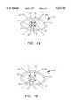
- FIG. 1Ais a plan view of an eye showing four light spots positioned on the eye's iris/pupil boundary in accordance with the present invention
- FIG. 1Bis a plan view of an eye showing four light spots positioned on the eye's iris/sclera boundary;
- FIG. 1Cis a plan view of an eye showing an ink ring affixed on the eye's iris/sclera boundary as well as four light spots positioned on the ink ring/sclera boundary;
- FIG. 1Dis a plan view of an eye showing a double ink ring affixed on the eye's sclera as well as four light spots positioned on the boundary between the inner and outer ink rings of the double ink ring;
- FIG. 1Eis a plan view of an eye with a reflection enhancing tack affixed thereto and showing four light spots positioned on the boundary between the eye and the tack;
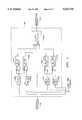
- FIG. 2is a block diagram of a preferred embodiment eye movement sensing system in accordance with the present invention.
- FIG. 3is a cross-sectional view of the fiber optic bundle arrangement in FIG. 2;
- FIG. 4is a block diagram of a preferred embodiment optical arrangement for the focusing optics in the delivery portion of the present invention.
- FIG. 5is a block diagram of a representative multiplexing peak circuit shown in FIG. 2.
- FIGS. 1A-1Eplan views of a human eye are shown and referenced generally by the numeral 10. From this planar perspective, eye 10 includes three visually adjoining surfaces, namely, a sclera or "white of the eye" 11, an iris 12 and a pupil 13. Each of sclera 11, iris 12, and pupil 13 has its own coefficient of reflection.
- the method of the present inventionis based on the preferable use of four spots of light, designated by circles 21, 22, 23 and 24.
- Spots 21 and 23are positioned on axis 25 while spots 22 and 24 are positioned on axis 26 as shown.
- Axes 25 and 26are orthogonal to one another.
- Spots 21, 22, 23 and 24are focused to be incident on and evenly spaced about either the iris/pupil boundary 14 as shown in FIG. 1A or the iris/sclera boundary 15 as shown in FIG. 1B.
- man-made boundariescan be used. For example, as shown in FIG.
- an ink ring 16can be placed on the iris/sclera boundary 15 to generate an ink ring/sclera boundary 17 that replaces or enhances boundary 15 in terms of its reflection differential with sclera 11.
- One ink that is commonly used for marking in ophthalmic proceduresis a gentian violet colored ink available under the tradename "Visitec”.
- a double ink ring 18having an inner ink ring 18a with a first coefficient of reflection and an outer ink ring 18b with a second coefficient of reflection can be placed on sclera 11. Spots 21, 22, 23 and 24 are then positioned on orthogonal axes 25 and 26 on the boundary 18c between ink rings 18a and 18b.
- FIG. 1EAnother alternative is shown in FIG. 1E where a circular reflection enhancing tack 19 is affixed to some portion of eye 10 (e.g., sclera 11) and spots 21, 22, 23 and 24 are positioned on orthogonal axes 25 and 26 crossing at the center of tack 19.
- a circular reflection enhancing tack 19is affixed to some portion of eye 10 (e.g., sclera 11) and spots 21, 22, 23 and 24 are positioned on orthogonal axes 25 and 26 crossing at the center of tack 19.
- the four spots 21, 22, 23 and 24are of equal energy and are spaced evenly about and on the circular boundary of interest. This placement provides for two-axis motion sensing in the following manner.
- Each light spot 21, 22, 23 and 24causes a certain amount of reflection at its position on the respective boundary. Since the respective boundary moves in coincidence with eye movement, the amount of reflection from light spots 21, 22, 23 and 24 changes in accordance with eye movement.
- horizontal or vertical eye movementis detected by changes in the amount of reflection from adjacent pairs of spots. For example, horizontal eye movement is monitored by comparing the combined reflection from light spots 21 and 24 with the combined reflection from light spots 22 and 23. In a similar fashion, vertical eye movement is monitored by comparing the combined reflection from light spots 21 and 22 with the combined reflection from light spots 23 and 24.
- iris/pupil boundary 14Utilizing iris/pupil boundary 14 is preferred because it is naturally occurring and because it presents the largest contrast in reflection characteristics. This is due mainly to the fact that pupil 13 reflects light directly back along its path of incidence while iris 12 reflects light back diffusely. Note that sclera 11 and ink ring 16 also reflect light diffusely with sclera 11 reflecting more than either iris 12 or ink ring 16. Accordingly, sclera 11 and iris 12 are used in combination (ie., iris/sclera boundary 15) and ink ring 16 can be used to replace or enhance iris/sclera boundary 15.
- the wavelength and power of light spots 21, 22, 23 and 24must be taken into consideration.
- the light spotsshould preferably lie outside the visible spectrum so as not to interfere or obstruct a surgeon's view of the eye undergoing the surgical procedure. Further, the light spots must be "eye safe" to meet the American National Standards Institute (ANSI) safety requirements. While a variety of light wavelengths satisfy the above requirements, by way of example, light spots 21, 22, 23 and 24 are in the near infrared 900 nanometer wavelength region. Light in this region meets the above rated criteria and is further produced by readily available, economically affordable light sources.
- One such light sourceis a high pulse repetition rate GaAs 905 nanometer laser operating at 4 kHz which produces an ANSI defined eye safe pulse of 10 nanojoules in a 50 nanosecond pulse.
- spots 21, 22, 23 and 24are varied in accordance with the boundary of interest.
- spot size for use with iris/pupil boundary 14is on the order of 1 millimeter while spot size for use with iris/sclera boundary 15 is on the order of 2 millimeters.
- spot size for use with iris/sclera boundary 15is on the order of 2 millimeters.
- the size of the spotsis not fixed and may indeed change with variations in patients and background illumination.
- System 100may be broken down into a delivery portion and a receiving portion. Essentially, the delivery portion projects light spots 21, 22, 23 and 24 onto eye 10 as described above, while the receiving portion monitors reflections caused by light spots 21, 22, 23 and 24.
- the delivery portionincludes a 905 nanometer pulsed diode laser 102 transmitting light through optical fiber 104 to an optical fiber assembly 105 that splits and delays each pulse from laser 102 into preferably four equal energy pulses.
- Assembly 105includes one-to-four optical splitter 106 that outputs four pulses of equal energy into optical fibers 108, 110, 112, 114.
- optical splittersare commercially available (e.g., model HLS2X4 manufactured by Canstar and model MMSC-0404-0850-A-H-1 manufactured by E-Tek Dynamics).
- each pulseis uniquely multiplexed by a respective fiber optic delay line (or optical modulator) 109, 111, 113 and 115.
- the pulse repetition frequency and delay increment xare chosen so that the data rate of system 100 is greater than the speed of the movement of interest.
- the data rate of system 100In terms of saccadic eye movement, the data rate of system 100 must be on the order of at least several hundred hertz.
- a system data rate of 4 kHzis achieved by 1) selecting a small but sufficient value for x to allow processor 160 to handle the data (e.g., 160 nanoseconds), and 2) selecting the time between pulses from laser 102 to be 250 microseconds (i.e., laser 102 is pulsed at a 4 kHz rate).
- Bundle 123arranges optical fibers 116, 118, 120 and 122 in a manner that produces a square (dotted line) with the center of each fiber at a corner thereof as shown in the cross-sectional view of FIG. 3.
- various well known structural features of bundle 123e.g., cladding on the fibers, spacers, insulation, etc. have been omitted.
- Light from assembly 105is passed through an optical polarizer 124 that attenuates the vertical component of the light and outputs horizontally polarized light beams as indicated by arrow 126.
- Horizontally polarized light beams 126pass to focusing optics 130 where spacing between beams 126 is adjusted based on the boundary of interest.
- a zoom capabilitycan be provided to allow for adjustment of the size of the pattern formed by spots 21, 22, 23 and 24. This capability allows system 100 to adapt to different patients, boundaries, etc.
- FIG. 4While a variety of optical arrangements are possible for focusing optics 130, one such arrangement is shown by way of example in FIG. 4.
- fiber optic bundle 123is positioned at the working distance of microscope objective 1302.
- the numerical aperture of microscope objective 1302is selected to be equal to the numerical aperture of fibers 116, 118, 120 and 122.
- Microscope objective 1302magnifies and collimates the incoming light.
- Zoom lens 1304provides an additional magnification factor for further tunability.
- Collimating lens 1306has a focal length that is equal to its distance from the image of zoom lens 1304 such that its output is collimated.
- the focal length of imaging lens 1308is the distance to the eye such that imaging lens 1308 focuses the light as four sharp spots on the corneal surface of the eye.
- polarizing beam splitting cube 140receives horizontally polarized light beams 126 from focusing optics 130.
- Polarization beamsplitting cubesare well known in the art.
- cube 140is a model 10FC16PB.5 manufactured by Newport-Klinger.
- Cube 140is configured to transmit only horizontal polarization and reflect vertical polarization. Accordingly, cube 140 transmits only horizontally polarized light beams 126 as indicated by arrow 142. Thus, it is only horizontally polarized light that is incident on eye 10 as spots 21, 22, 23 and 24.
- the light energyis depolarized (i.e., it has both horizontal and vertical polarization components) as indicated by crossed arrows 150.
- the vertical component of the reflected lightis then directed/reflected as indicated by arrow 152.
- cube 140serves to separate the transmitted light energy from the reflected light energy for accurate measurement.
- the vertically polarized portion of the reflection from spots 21, 22, 23 and 24,is passed through focusing lens 154 for imaging onto an infrared detector 156.
- Detector 156passes its signal to a multiplexing peak detecting circuit 158 which is essentially a peak sample and hold circuit, a variety of which are well known in the art.
- Circuit 158is configured to sample (and hold the peak value from) detector 156 in accordance with the pulse repetition frequency of laser 102 and the delay x. For example, if the pulse repetition frequency of laser 102 is 4 kHz, circuit 158 gathers reflections from spots 21, 22, 23 and 24 every 250 microseconds.
- infrared detector 156is an avalanche photodiode model C30916E manufactured by EG&G.
- a representative time multiplexing peak circuit 158is shown in greater detail in the block diagram of FIG. 5.
- the detector signal output from detector 156is input to four peak and hold circuits 1581, 1582, 1583 and 1584.
- the detector outputwill consist of four pulses separated in time by the delays associated with optical delay lines 109, 111, 113 and 115 shown in FIG. 2. These four time separated pulses are fed to peak and hold circuits 1581, 1582, 1583 and 1584.
- Input enabling signalsare also fed to the peak and hold circuits in synchronism with the laser fire command.
- the enabling signal for each peak and hold circuitis delayed by delay circuits 1585, 1586, 1587 and 1588.
- the delaysare set to correspond to the delays of delay lines 109, 111, 113 and 115 to allow each of the four pulses to be input to the peak and hold circuits.
- delay circuit 1585causes a time delay of zero corresponding to delay line 109
- delay circuit 1586causes a time delay of x corresponding to delay line 111, etc.
- output multiplexer 1589reads the value held by each peak and hold circuit and inputs them sequentially to processor 160.
- the values associated with the reflected energy for each group of four spotsare used to determine the horizontal and vertical components of eye movement.
- R 21 , R 22 , R 23 and R 24represent the detected amount of reflection from one group of spots 21, 22, 23 and 24, respectively.
- a quantitative amount of horizontal movementis determined directly from the normalized relationship ##EQU1## while a quantitative amount of vertical movement is determined directly from the normalized relationship ##EQU2## Note that normalizing (i.e., dividing by R 21 +R 22 +R 23 +R 24 ) reduces the effects of variations in signal strength.
- the reflection differentials indicating eye movementcan be used in a variety of ways. For example, an excessive amount of eye movement may be used to trigger an alarm 170.
- the reflection differentialmay be used as a feedback control for tracking servos 172 used to position an ablation laser. Still further, the reflection differentials can be displayed on display 174 for monitoring or teaching purposes.
- Eye movementis sensed in accordance with a non-intrusive method and apparatus.
- the present inventionwill find great utility in a variety of ophthalmic surgical procedures without any detrimental effects to the eye or interruption of a surgeon's view. Further, data rates needed to sense saccadic eye movement are easily and economically achieved.
Landscapes
- Health & Medical Sciences (AREA)
- Life Sciences & Earth Sciences (AREA)
- Engineering & Computer Science (AREA)
- Molecular Biology (AREA)
- Animal Behavior & Ethology (AREA)
- Biophysics (AREA)
- Ophthalmology & Optometry (AREA)
- Biomedical Technology (AREA)
- Heart & Thoracic Surgery (AREA)
- Medical Informatics (AREA)
- Human Computer Interaction (AREA)
- Surgery (AREA)
- Physics & Mathematics (AREA)
- General Health & Medical Sciences (AREA)
- Public Health (AREA)
- Veterinary Medicine (AREA)
- Eye Examination Apparatus (AREA)
- Laser Surgery Devices (AREA)
- Radar Systems Or Details Thereof (AREA)
- Length Measuring Devices By Optical Means (AREA)
- Prostheses (AREA)
Abstract
Description
Claims (5)
Priority Applications (13)
| Application Number | Priority Date | Filing Date | Title |
|---|---|---|---|
| US08/232,990US5632742A (en) | 1994-04-25 | 1994-04-25 | Eye movement sensing method and system |
| TW084103172ATW311881B (en) | 1994-04-25 | 1995-03-31 | |
| IL11335495AIL113354A (en) | 1994-04-25 | 1995-04-13 | Eye movement sensing method and system |
| ES95916962TES2192576T3 (en) | 1994-04-25 | 1995-04-18 | PROCEDURE AND SYSTEM OF DETECTION OF MOVEMENTS OF THE EYE. |
| CA002188038ACA2188038C (en) | 1994-04-25 | 1995-04-18 | Eye movement sensing method and system |
| JP52768095AJP3499874B2 (en) | 1994-04-25 | 1995-04-18 | Eye movement detection system |
| PCT/US1995/004524WO1995028879A1 (en) | 1994-04-25 | 1995-04-18 | Eye movement sensing method and system |
| DE69529681TDE69529681T2 (en) | 1994-04-25 | 1995-04-18 | METHOD AND ARRANGEMENT FOR DISPLAYING EYE MOVEMENTS |
| AT95916962TATE232694T1 (en) | 1994-04-25 | 1995-04-18 | METHOD AND ARRANGEMENT FOR DISPLAYING EYE MOVEMENTS |
| EP95916962AEP0789531B1 (en) | 1994-04-25 | 1995-04-18 | Eye movement sensing method and system |
| AU23825/95AAU2382595A (en) | 1994-04-25 | 1995-04-18 | Eye movement sensing method and system |
| ZA953144AZA953144B (en) | 1994-04-25 | 1995-04-19 | Eye movement sensing method and system |
| US08/854,870US6315773B1 (en) | 1994-04-25 | 1997-05-12 | Eye movement sensing system |
Applications Claiming Priority (1)
| Application Number | Priority Date | Filing Date | Title |
|---|---|---|---|
| US08/232,990US5632742A (en) | 1994-04-25 | 1994-04-25 | Eye movement sensing method and system |
Related Child Applications (1)
| Application Number | Title | Priority Date | Filing Date |
|---|---|---|---|
| US08/854,870ContinuationUS6315773B1 (en) | 1994-04-25 | 1997-05-12 | Eye movement sensing system |
Publications (1)
| Publication Number | Publication Date |
|---|---|
| US5632742Atrue US5632742A (en) | 1997-05-27 |
Family
ID=22875419
Family Applications (2)
| Application Number | Title | Priority Date | Filing Date |
|---|---|---|---|
| US08/232,990Expired - LifetimeUS5632742A (en) | 1994-04-25 | 1994-04-25 | Eye movement sensing method and system |
| US08/854,870Expired - Fee RelatedUS6315773B1 (en) | 1994-04-25 | 1997-05-12 | Eye movement sensing system |
Family Applications After (1)
| Application Number | Title | Priority Date | Filing Date |
|---|---|---|---|
| US08/854,870Expired - Fee RelatedUS6315773B1 (en) | 1994-04-25 | 1997-05-12 | Eye movement sensing system |
Country Status (11)
| Country | Link |
|---|---|
| US (2) | US5632742A (en) |
| EP (1) | EP0789531B1 (en) |
| JP (1) | JP3499874B2 (en) |
| AT (1) | ATE232694T1 (en) |
| AU (1) | AU2382595A (en) |
| DE (1) | DE69529681T2 (en) |
| ES (1) | ES2192576T3 (en) |
| IL (1) | IL113354A (en) |
| TW (1) | TW311881B (en) |
| WO (1) | WO1995028879A1 (en) |
| ZA (1) | ZA953144B (en) |
Cited By (93)
| Publication number | Priority date | Publication date | Assignee | Title |
|---|---|---|---|---|
| WO1999018868A1 (en) | 1997-10-10 | 1999-04-22 | Visx Incorporated | Eye tracking device for laser eye surgery using corneal margin detection |
| US5966197A (en)* | 1998-04-21 | 1999-10-12 | Visx, Incorporated | Linear array eye tracker |
| US6095651A (en)* | 1996-12-23 | 2000-08-01 | University Of Rochester | Method and apparatus for improving vision and the resolution of retinal images |
| US6159202A (en)* | 1995-09-29 | 2000-12-12 | Nidex Co., Ltd. | Corneal surgery apparatus |
| US6173069B1 (en) | 1998-01-09 | 2001-01-09 | Sharp Laboratories Of America, Inc. | Method for adapting quantization in video coding using face detection and visual eccentricity weighting |
| US6179422B1 (en) | 1998-04-27 | 2001-01-30 | Ming Lai | Optical tracking device |
| US6199986B1 (en) | 1999-10-21 | 2001-03-13 | University Of Rochester | Rapid, automatic measurement of the eye's wave aberration |
| US6210169B1 (en)* | 1997-01-31 | 2001-04-03 | Lasersight Technologies, Inc. | Device and method for simulating ophthalmic surgery |
| WO2001034021A1 (en)* | 1999-10-29 | 2001-05-17 | Chronos Vision Gmbh | Method and assembly for detecting multi-dimensional eye movements and a staining tincture therefor |
| US6271914B1 (en) | 1996-11-25 | 2001-08-07 | Autonomous Technologies Corporation | Objective measurement and correction of optical systems using wavefront analysis |
| US6270221B1 (en) | 1998-08-19 | 2001-08-07 | Alcon Universal Ltd. | Apparatus and method for measuring vision defects of a human eye |
| US6283954B1 (en) | 1998-04-21 | 2001-09-04 | Visx, Incorporated | Linear array eye tracker |
| US6299308B1 (en)* | 1999-04-02 | 2001-10-09 | Cybernet Systems Corporation | Low-cost non-imaging eye tracker system for computer control |
| US6302879B1 (en)* | 1994-04-25 | 2001-10-16 | Autonomous Technologies Corp. | Laser beam delivery and eye tracking system |
| WO2001080791A2 (en) | 2000-04-25 | 2001-11-01 | Alcon Universal Ltd. | Laser ablation zone restriction system and method |
| US6315773B1 (en)* | 1994-04-25 | 2001-11-13 | Autonomous Technologies Corporation | Eye movement sensing system |
| US6322216B1 (en) | 1999-10-07 | 2001-11-27 | Visx, Inc | Two camera off-axis eye tracker for laser eye surgery |
| WO2001078584A3 (en)* | 2000-04-19 | 2002-03-28 | Alcon Universal Ltd | Eye registration and astigmatism alignment control systems and method |
| US6394605B1 (en) | 2001-05-23 | 2002-05-28 | Alcon Universal Ltd. | Fogging method for a wavefront sensor |
| WO2002064031A2 (en) | 2001-02-09 | 2002-08-22 | Sensomotoric Instruments Gmbh | Multidimensional eye tracking and position measurement system |
| DE10118314A1 (en)* | 2001-04-11 | 2002-11-07 | Bioshape Ag | Process for the spatial comparison of images taken at different times |
| US6497483B2 (en) | 2000-05-08 | 2002-12-24 | Alcon, Inc. | Apparatus and method for objective measurement of optical systems using wavefront analysis |
| US20030078753A1 (en)* | 2000-03-22 | 2003-04-24 | Campin John Alfred | Optimization of ablation correction of an optical system and associated methods |
| US6554429B1 (en) | 2001-10-15 | 2003-04-29 | Alcon, Inc. | Method for determining accommodation |
| US20030090626A1 (en)* | 2001-11-13 | 2003-05-15 | Ming Lai | Optical tracking device employing scanning beams on symmetric reference |
| US6569154B2 (en)* | 2000-03-22 | 2003-05-27 | Alcon, Inc. | Optimization of ablation correction of an optical system and associated methods |
| US6578963B2 (en) | 2000-04-19 | 2003-06-17 | Alcon Universal Ltd. | Wavefront sensor for objective measurement of an optical system and associated methods |
| US20030120266A1 (en)* | 2001-12-03 | 2003-06-26 | Masanao Fujieda | Ophthalmic apparatus and corneal surgery apparatus |
| US6604825B2 (en) | 2000-04-03 | 2003-08-12 | Ming Lai | Hybrid tracking system |
| US20030197908A1 (en)* | 2002-04-22 | 2003-10-23 | Visx, Inc. | Beam position monitoring for laser eye surgery |
| US20040044333A1 (en)* | 2002-08-29 | 2004-03-04 | Motohiro Sugiura | Corneal surgery apparatus |
| US6702809B1 (en) | 1989-02-06 | 2004-03-09 | Visx, Inc. | System for detecting, measuring and compensating for lateral movements of a target |
| US6757310B2 (en) | 2001-01-17 | 2004-06-29 | Ming Lai | Solid-state laser for customized cornea ablation |
| US20040130677A1 (en)* | 1998-08-19 | 2004-07-08 | Alcon, Inc. | Apparatus and method for measuring vision defects of a human eye |
| US20040143246A1 (en)* | 2003-01-15 | 2004-07-22 | Naoyuki Maeda | Corneal surgery apparatus |
| US20040143244A1 (en)* | 2000-04-19 | 2004-07-22 | Alcon Refractivehorizons, Inc. | Eye registration and astigmatism alignment control systems and method |
| US20040160576A1 (en)* | 2002-11-20 | 2004-08-19 | Ming Lai | Method and apparatus for obtaining patient-verified prescription of high order aberrations |
| US6786899B1 (en)* | 1998-07-21 | 2004-09-07 | Ming Lai | Eye tracking employing a retro-reflective disk |
| US20040227699A1 (en)* | 2003-05-15 | 2004-11-18 | Mitchell Brian T. | Foveated display eye-tracking system and method |
| US20040243113A1 (en)* | 2003-05-30 | 2004-12-02 | Motohiro Sugiura | Ophthalmic laser irradiation apparatus |
| US20050068185A1 (en)* | 2003-09-29 | 2005-03-31 | Nattel Group, Inc. | System and method for monitoring the operational condition of a motor vehicle |
| EP1532922A1 (en)* | 2003-11-20 | 2005-05-25 | 20/10 Perfect Vision Optische Geräte GmbH | Eye position control monitor for laser vision correction |
| US20050110950A1 (en)* | 2003-03-13 | 2005-05-26 | Thorpe William P. | Saccadic motion sensing |
| US20050124983A1 (en)* | 1996-11-25 | 2005-06-09 | Frey Rudolph W. | Method for determining and correcting vision |
| US20050137586A1 (en)* | 2003-12-23 | 2005-06-23 | Gray Gary P. | Hybrid eye tracking system and associated methods |
| US20050146425A1 (en)* | 2003-12-24 | 2005-07-07 | Sanjeev Nath | Method for intelligent crescendo system |
| US20050185138A1 (en)* | 2004-02-19 | 2005-08-25 | Visx, Incorporated | Methods and systems for differentiating left and right eye images |
| US7001377B1 (en) | 2003-12-22 | 2006-02-21 | Alcon Refractivehorizons, Inc. | Optical tracking system and associated methods |
| US7044602B2 (en) | 2002-05-30 | 2006-05-16 | Visx, Incorporated | Methods and systems for tracking a torsional orientation and position of an eye |
| US20060161144A1 (en)* | 2003-12-22 | 2006-07-20 | Haizhang Li | Optical tracking system and associated methods |
| AU2002313824B2 (en)* | 2001-09-12 | 2006-08-17 | Johnson & Johnson Vision Care, Inc. | Ophthalmic wavefront measuring devices |
| US7226443B1 (en) | 2003-11-07 | 2007-06-05 | Alcon Refractivehorizons, Inc. | Optimization of ablation correction of an optical system and associated methods |
| US20070189341A1 (en)* | 2006-02-14 | 2007-08-16 | Kendall Belsley | System and method for providing chirped electromagnetic radiation |
| US7284862B1 (en) | 2003-11-13 | 2007-10-23 | Md Lasers & Instruments, Inc. | Ophthalmic adaptive-optics device with a fast eye tracker and a slow deformable mirror |
| US20070273832A1 (en)* | 2006-05-10 | 2007-11-29 | Weinblatt Lee S | Use of saccadic eye motion to indicate the level of human interest in response to visual stimuli |
| US20080069410A1 (en)* | 2006-09-18 | 2008-03-20 | Jong Gook Ko | Iris recognition method and apparatus thereof |
| US20080269731A1 (en)* | 2003-11-19 | 2008-10-30 | Casimir Andrew Swinger | Method and apparatus applying patient-verified prescription of high order aberrations |
| US20080276178A1 (en)* | 2007-05-04 | 2008-11-06 | Apple Inc. | Adjusting media display in a personal display system based on perspective |
| US20090216093A1 (en)* | 2004-09-21 | 2009-08-27 | Digital Signal Corporation | System and method for remotely monitoring physiological functions |
| US7655002B2 (en) | 1996-03-21 | 2010-02-02 | Second Sight Laser Technologies, Inc. | Lenticular refractive surgery of presbyopia, other refractive errors, and cataract retardation |
| US20100079356A1 (en)* | 2008-09-30 | 2010-04-01 | Apple Inc. | Head-mounted display apparatus for retaining a portable electronic device with display |
| US20100245767A1 (en)* | 2009-03-27 | 2010-09-30 | Utechzone Co., Ltd. | Eye-tracking method and eye-tracking system for implementing the same |
| CN101437440B (en)* | 2005-12-14 | 2011-09-07 | 数字信号公司 | Systems and methods for tracking eye movements |
| US8262646B2 (en) | 2006-01-20 | 2012-09-11 | Lensar, Inc. | System and method for providing the shaped structural weakening of the human lens with a laser |
| WO2012130818A1 (en)* | 2011-03-25 | 2012-10-04 | National Digital Research Centre | Apparatus for modelling ocular structures |
| US8382745B2 (en) | 2009-07-24 | 2013-02-26 | Lensar, Inc. | Laser system and method for astigmatic corrections in association with cataract treatment |
| US20130060241A1 (en)* | 2010-04-27 | 2013-03-07 | Daniel S. Haddad | Dynamic real time active pupil centroid compensation |
| US8465478B2 (en) | 2009-07-24 | 2013-06-18 | Lensar, Inc. | System and method for performing LADAR assisted procedures on the lens of an eye |
| US8480659B2 (en) | 2008-07-25 | 2013-07-09 | Lensar, Inc. | Method and system for removal and replacement of lens material from the lens of an eye |
| US8500723B2 (en) | 2008-07-25 | 2013-08-06 | Lensar, Inc. | Liquid filled index matching device for ophthalmic laser procedures |
| US8512320B1 (en)* | 2007-06-26 | 2013-08-20 | Bausch & Lomb Incorporated | Method for modifying the refractive index of ocular tissues |
| US8556425B2 (en) | 2010-02-01 | 2013-10-15 | Lensar, Inc. | Purkinjie image-based alignment of suction ring in ophthalmic applications |
| US8582085B2 (en) | 2005-02-14 | 2013-11-12 | Digital Signal Corporation | Chirped coherent laser radar with multiple simultaneous measurements |
| USD694890S1 (en) | 2010-10-15 | 2013-12-03 | Lensar, Inc. | Laser system for treatment of the eye |
| USD695408S1 (en) | 2010-10-15 | 2013-12-10 | Lensar, Inc. | Laser system for treatment of the eye |
| US8605008B1 (en)* | 2007-05-04 | 2013-12-10 | Apple Inc. | Head-mounted display |
| US8617146B2 (en) | 2009-07-24 | 2013-12-31 | Lensar, Inc. | Laser system and method for correction of induced astigmatism |
| US8717545B2 (en) | 2009-02-20 | 2014-05-06 | Digital Signal Corporation | System and method for generating three dimensional images using lidar and video measurements |
| US8733934B2 (en) | 2011-05-16 | 2014-05-27 | Wavelight Gmbh | Instrument for examining or machining a human eye |
| US8758332B2 (en) | 2009-07-24 | 2014-06-24 | Lensar, Inc. | Laser system and method for performing and sealing corneal incisions in the eye |
| US8801186B2 (en) | 2010-10-15 | 2014-08-12 | Lensar, Inc. | System and method of scan controlled illumination of structures within an eye |
| US20140354953A1 (en)* | 2013-05-31 | 2014-12-04 | Pixart Imaging Inc. | Tracking device and optical assembly thereof |
| US9180051B2 (en) | 2006-01-20 | 2015-11-10 | Lensar Inc. | System and apparatus for treating the lens of an eye |
| US9245497B2 (en) | 2012-11-01 | 2016-01-26 | Google Technology Holdings LLC | Systems and methods for configuring the display resolution of an electronic device based on distance and user presbyopia |
| US9298283B1 (en) | 2015-09-10 | 2016-03-29 | Connectivity Labs Inc. | Sedentary virtual reality method and systems |
| US9375349B2 (en) | 2006-01-20 | 2016-06-28 | Lensar, Llc | System and method for providing laser shot patterns to the lens of an eye |
| US9393154B2 (en) | 2011-10-28 | 2016-07-19 | Raymond I Myers | Laser methods for creating an antioxidant sink in the crystalline lens for the maintenance of eye health and physiology and slowing presbyopia development |
| US9545338B2 (en) | 2006-01-20 | 2017-01-17 | Lensar, Llc. | System and method for improving the accommodative amplitude and increasing the refractive power of the human lens with a laser |
| US20180025226A1 (en)* | 2016-07-22 | 2018-01-25 | Yung-Hui Li | Smart eyeglasses with iris recognition device |
| US9889043B2 (en) | 2006-01-20 | 2018-02-13 | Lensar, Inc. | System and apparatus for delivering a laser beam to the lens of an eye |
| US9961307B1 (en) | 2014-06-30 | 2018-05-01 | Lee S. Weinblatt | Eyeglass recorder with multiple scene cameras and saccadic motion detection |
| US10016130B2 (en) | 2015-09-04 | 2018-07-10 | University Of Massachusetts | Eye tracker system and methods for detecting eye parameters |
| US10463541B2 (en) | 2011-03-25 | 2019-11-05 | Lensar, Inc. | System and method for correcting astigmatism using multiple paired arcuate laser generated corneal incisions |
Families Citing this family (16)
| Publication number | Priority date | Publication date | Assignee | Title |
|---|---|---|---|---|
| US6302877B1 (en)* | 1994-06-29 | 2001-10-16 | Luis Antonio Ruiz | Apparatus and method for performing presbyopia corrective surgery |
| DE19962107A1 (en) | 1999-12-22 | 2001-06-28 | Wavelight Laser Technologie Ag | Photo-refractive keratectomy device for treatment of eye, directs centering and fixing light beams of different wavelengths onto eye |
| US7217266B2 (en)* | 2001-05-30 | 2007-05-15 | Anderson R Rox | Apparatus and method for laser treatment with spectroscopic feedback |
| US20030225398A1 (en)* | 2002-05-28 | 2003-12-04 | Neil Zepkin | Zoom device for eye tracker control system and associated methods |
| US6658282B1 (en)* | 2002-12-19 | 2003-12-02 | Bausch & Lomb Incorporated | Image registration system and method |
| DE112004002612T5 (en)* | 2004-01-09 | 2006-11-09 | Customvis Plc, Balcatta | Limbus-based tracking of eye movements |
| DE102004018628A1 (en)* | 2004-04-16 | 2005-11-03 | Carl Zeiss Meditec Ag | Device and method for detecting eye movements |
| DE102004025999A1 (en)* | 2004-05-27 | 2005-12-15 | Quintis Gmbh | Three-dimensional eye position detector for laser eye operation, has sensor for detecting reference object in two translatory directions, and distances of scanning points |
| WO2006119584A1 (en)* | 2005-05-13 | 2006-11-16 | Customvis Plc | Fast response eye tracking |
| AU2006246323B2 (en)* | 2005-05-13 | 2012-10-18 | Cv Laser Pty Ltd | Fast response eye tracking |
| WO2009135084A1 (en)* | 2008-04-30 | 2009-11-05 | Amo Development, Llc | System and method for controlling measurement in an eye during ophthalmic procedure |
| FR2945434B1 (en)* | 2009-05-12 | 2012-12-14 | Essilor Int | PAIR OF OPHTHALMIC GLASSES SUITABLE FOR CHARACTERIZING EYE CONVERGENCE OF A BEARER. |
| FR2945435B1 (en)* | 2009-05-12 | 2012-12-14 | Essilor Int | PAIR OF OPHTHALMIC GLASSES SUITABLE FOR CHARACTERIZING A DIRECTION OF LOOKING AT A BEARER. |
| US8955973B2 (en)* | 2012-01-06 | 2015-02-17 | Google Inc. | Method and system for input detection using structured light projection |
| US20150009238A1 (en)* | 2013-07-03 | 2015-01-08 | Nvidia Corporation | Method for zooming into and out of an image shown on a display |
| US10617321B2 (en) | 2016-05-05 | 2020-04-14 | Walmart Apollo, Llc | Methods and Systems for food ordering |
Citations (8)
| Publication number | Priority date | Publication date | Assignee | Title |
|---|---|---|---|---|
| US4438765A (en)* | 1981-06-04 | 1984-03-27 | Jack Wilinsky | Motion sensitive firable device |
| US4443075A (en)* | 1981-06-26 | 1984-04-17 | Sri International | Stabilized visual system |
| US4702245A (en)* | 1983-10-29 | 1987-10-27 | Meditec-Reinhardt Thyzel Gmbh | Pulsed laser for medical applications |
| US4848340A (en)* | 1988-02-10 | 1989-07-18 | Intelligent Surgical Lasers | Eyetracker and method of use |
| US4972836A (en)* | 1989-12-18 | 1990-11-27 | General Electric Company | Motion detector for high-resolution magnetic resonance imaging |
| US5057102A (en)* | 1989-05-29 | 1991-10-15 | Kabushiki Kaisha Topcon | Contrast adjustor for aiming laser |
| US5302979A (en)* | 1989-07-28 | 1994-04-12 | Canon Kabushiki Kaisha | Ophthalmic apparatus capable of measuring the shape of a cornea |
| US5329544A (en)* | 1992-12-18 | 1994-07-12 | Mli Industrial Lasers (1992) Ltd. | Laser control system |
Family Cites Families (25)
| Publication number | Priority date | Publication date | Assignee | Title |
|---|---|---|---|---|
| US3712716A (en) | 1971-04-09 | 1973-01-23 | Stanford Research Inst | Eye tracker |
| US3864030A (en) | 1972-07-11 | 1975-02-04 | Acuity Syst | Eye position measuring technique |
| DE2450095A1 (en)* | 1974-10-22 | 1976-04-29 | Messerschmitt Boelkow Blohm | Direction of vision and field of vision meter - uses infra red light source with automatic measurement |
| US4069823A (en) | 1976-04-19 | 1978-01-24 | Viktor Leonidovich Isakov | Apparatus for laser therapy |
| DE3245939C2 (en) | 1982-12-11 | 1985-12-19 | Fa. Carl Zeiss, 7920 Heidenheim | Device for generating an image of the fundus |
| CA1243732A (en) | 1983-11-17 | 1988-10-25 | Francis A. L'esperance | Method and apparatus for ophthalmological surgery |
| US4718418A (en) | 1983-11-17 | 1988-01-12 | Lri L.P. | Apparatus for ophthalmological surgery |
| US4729372A (en) | 1983-11-17 | 1988-03-08 | Lri L.P. | Apparatus for performing ophthalmic laser surgery |
| US4669466A (en) | 1985-01-16 | 1987-06-02 | Lri L.P. | Method and apparatus for analysis and correction of abnormal refractive errors of the eye |
| AU606315B2 (en) | 1985-09-12 | 1991-02-07 | Summit Technology, Inc. | Surface erosion using lasers |
| FR2598088B1 (en) | 1986-04-30 | 1991-03-29 | Inst Nat Sante Rech Med | SYSTEMATIZED TREATMENT INSTRUMENT, IN PARTICULAR USING LASER ENERGY USEFUL FOR EXAMPLE IN DERMATOLOGY |
| US4759615A (en)* | 1986-06-09 | 1988-07-26 | American Sterilizer Company | Illumination system using amplified polarized light |
| US4901718A (en) | 1988-02-02 | 1990-02-20 | Intelligent Surgical Lasers | 3-Dimensional laser beam guidance system |
| US4881808A (en) | 1988-02-10 | 1989-11-21 | Intelligent Surgical Lasers | Imaging system for surgical lasers |
| US5098426A (en) | 1989-02-06 | 1992-03-24 | Phoenix Laser Systems, Inc. | Method and apparatus for precision laser surgery |
| US5048946A (en) | 1990-05-15 | 1991-09-17 | Phoenix Laser Systems, Inc. | Spectral division of reflected light in complex optical diagnostic and therapeutic systems |
| US5220361A (en)* | 1991-06-05 | 1993-06-15 | Allergan Humphrey | Gaze tracking for field analyzer |
| US5178617A (en) | 1991-07-09 | 1993-01-12 | Laserscope | System for controlled distribution of laser dosage |
| WO1993016631A1 (en) | 1992-02-27 | 1993-09-02 | Phoenix Laser Systems, Inc. | Automated laser workstation for high precision surgical and industrial interventions |
| US5331131A (en) | 1992-09-29 | 1994-07-19 | Bausch & Lomb Incorporated | Scanning technique for laser ablation |
| US5345281A (en)* | 1992-12-17 | 1994-09-06 | John Taboada | Eye tracking system and method |
| US5350374A (en) | 1993-03-18 | 1994-09-27 | Smith Robert F | Topography feedback control system for photoablation |
| US5410376A (en) | 1994-02-04 | 1995-04-25 | Pulse Medical Instruments | Eye tracking method and apparatus |
| US5632742A (en)* | 1994-04-25 | 1997-05-27 | Autonomous Technologies Corp. | Eye movement sensing method and system |
| JP5323038B2 (en) | 2010-12-14 | 2013-10-23 | 積水化学工業株式会社 | Encapsulant for optical semiconductor device and optical semiconductor device using the same |
- 1994
- 1994-04-25USUS08/232,990patent/US5632742A/ennot_activeExpired - Lifetime
- 1995
- 1995-03-31TWTW084103172Apatent/TW311881B/zhactive
- 1995-04-13ILIL11335495Apatent/IL113354A/ennot_activeIP Right Cessation
- 1995-04-18WOPCT/US1995/004524patent/WO1995028879A1/enactiveIP Right Grant
- 1995-04-18JPJP52768095Apatent/JP3499874B2/ennot_activeExpired - Fee Related
- 1995-04-18DEDE69529681Tpatent/DE69529681T2/ennot_activeExpired - Fee Related
- 1995-04-18AUAU23825/95Apatent/AU2382595A/ennot_activeAbandoned
- 1995-04-18ESES95916962Tpatent/ES2192576T3/ennot_activeExpired - Lifetime
- 1995-04-18EPEP95916962Apatent/EP0789531B1/ennot_activeExpired - Lifetime
- 1995-04-18ATAT95916962Tpatent/ATE232694T1/ennot_activeIP Right Cessation
- 1995-04-19ZAZA953144Apatent/ZA953144B/enunknown
- 1997
- 1997-05-12USUS08/854,870patent/US6315773B1/ennot_activeExpired - Fee Related
Patent Citations (8)
| Publication number | Priority date | Publication date | Assignee | Title |
|---|---|---|---|---|
| US4438765A (en)* | 1981-06-04 | 1984-03-27 | Jack Wilinsky | Motion sensitive firable device |
| US4443075A (en)* | 1981-06-26 | 1984-04-17 | Sri International | Stabilized visual system |
| US4702245A (en)* | 1983-10-29 | 1987-10-27 | Meditec-Reinhardt Thyzel Gmbh | Pulsed laser for medical applications |
| US4848340A (en)* | 1988-02-10 | 1989-07-18 | Intelligent Surgical Lasers | Eyetracker and method of use |
| US5057102A (en)* | 1989-05-29 | 1991-10-15 | Kabushiki Kaisha Topcon | Contrast adjustor for aiming laser |
| US5302979A (en)* | 1989-07-28 | 1994-04-12 | Canon Kabushiki Kaisha | Ophthalmic apparatus capable of measuring the shape of a cornea |
| US4972836A (en)* | 1989-12-18 | 1990-11-27 | General Electric Company | Motion detector for high-resolution magnetic resonance imaging |
| US5329544A (en)* | 1992-12-18 | 1994-07-12 | Mli Industrial Lasers (1992) Ltd. | Laser control system |
Cited By (192)
| Publication number | Priority date | Publication date | Assignee | Title |
|---|---|---|---|---|
| US6702809B1 (en) | 1989-02-06 | 2004-03-09 | Visx, Inc. | System for detecting, measuring and compensating for lateral movements of a target |
| US6626896B2 (en) | 1994-04-25 | 2003-09-30 | Alcon, Inc. | Method of correcting vision |
| US6451008B1 (en)* | 1994-04-25 | 2002-09-17 | Alcon, Inc. | Laser beam delivery and eye tracking system |
| US6302879B1 (en)* | 1994-04-25 | 2001-10-16 | Autonomous Technologies Corp. | Laser beam delivery and eye tracking system |
| US6626897B2 (en)* | 1994-04-25 | 2003-09-30 | Alcon, Inc. | Method of redirecting an ablating laser beam |
| US6626894B2 (en)* | 1994-04-25 | 2003-09-30 | Alcon, Inc. | Method of ablating a moving eye |
| US6626898B2 (en) | 1994-04-25 | 2003-09-30 | Alcon, Inc. | Flying spot laser ablation method |
| US6626895B2 (en) | 1994-04-25 | 2003-09-30 | Alcon, Inc. | Laser beam delivery system |
| US6315773B1 (en)* | 1994-04-25 | 2001-11-13 | Autonomous Technologies Corporation | Eye movement sensing system |
| US6626893B2 (en)* | 1994-04-25 | 2003-09-30 | Alcon, Inc. | Method of correcting vision |
| US6585726B2 (en)* | 1994-04-25 | 2003-07-01 | Alcon, Inc. | Method of maintaining spacing in an ablation pattern |
| US6491687B1 (en) | 1995-09-29 | 2002-12-10 | Nidek Co., Ltd. | Corneal Surgery apparatus |
| US6159202A (en)* | 1995-09-29 | 2000-12-12 | Nidex Co., Ltd. | Corneal surgery apparatus |
| US6986765B2 (en) | 1995-09-29 | 2006-01-17 | Nidek Co., Ltd. | Corneal surgery apparatus |
| US7655002B2 (en) | 1996-03-21 | 2010-02-02 | Second Sight Laser Technologies, Inc. | Lenticular refractive surgery of presbyopia, other refractive errors, and cataract retardation |
| US6271914B1 (en) | 1996-11-25 | 2001-08-07 | Autonomous Technologies Corporation | Objective measurement and correction of optical systems using wavefront analysis |
| US6271915B1 (en) | 1996-11-25 | 2001-08-07 | Autonomous Technologies Corporation | Objective measurement and correction of optical systems using wavefront analysis |
| US20050124983A1 (en)* | 1996-11-25 | 2005-06-09 | Frey Rudolph W. | Method for determining and correcting vision |
| US7416305B2 (en) | 1996-12-23 | 2008-08-26 | University Of Rochester | Method and apparatus for improving vision and the resolution of retinal images |
| US20060044510A1 (en)* | 1996-12-23 | 2006-03-02 | University Of Rochester | Method and apparatus for improving vision and the resolution of retinal images |
| US6948818B2 (en) | 1996-12-23 | 2005-09-27 | University Of Rochester | Method and apparatus for improving vision and the resolution of retinal images |
| US6095651A (en)* | 1996-12-23 | 2000-08-01 | University Of Rochester | Method and apparatus for improving vision and the resolution of retinal images |
| US6379005B1 (en) | 1996-12-23 | 2002-04-30 | University Of Rochester | Method and apparatus for improving vision and the resolution of retinal images |
| US6210169B1 (en)* | 1997-01-31 | 2001-04-03 | Lasersight Technologies, Inc. | Device and method for simulating ophthalmic surgery |
| WO1999018868A1 (en) | 1997-10-10 | 1999-04-22 | Visx Incorporated | Eye tracking device for laser eye surgery using corneal margin detection |
| US6299307B1 (en) | 1997-10-10 | 2001-10-09 | Visx, Incorporated | Eye tracking device for laser eye surgery using corneal margin detection |
| US7181050B1 (en) | 1998-01-09 | 2007-02-20 | Sharp Laboratories Of America, Inc. | Method for adapting quantization in video coding using face detection and visual eccentricity weighting |
| US6173069B1 (en) | 1998-01-09 | 2001-01-09 | Sharp Laboratories Of America, Inc. | Method for adapting quantization in video coding using face detection and visual eccentricity weighting |
| US6283954B1 (en) | 1998-04-21 | 2001-09-04 | Visx, Incorporated | Linear array eye tracker |
| US5966197A (en)* | 1998-04-21 | 1999-10-12 | Visx, Incorporated | Linear array eye tracker |
| US6367931B2 (en) | 1998-04-27 | 2002-04-09 | Ming Lai | Optical tracking based on a change in optical reflection across a reference mark on an object to be tracked |
| US6179422B1 (en) | 1998-04-27 | 2001-01-30 | Ming Lai | Optical tracking device |
| US6786899B1 (en)* | 1998-07-21 | 2004-09-07 | Ming Lai | Eye tracking employing a retro-reflective disk |
| US6270221B1 (en) | 1998-08-19 | 2001-08-07 | Alcon Universal Ltd. | Apparatus and method for measuring vision defects of a human eye |
| US20040130677A1 (en)* | 1998-08-19 | 2004-07-08 | Alcon, Inc. | Apparatus and method for measuring vision defects of a human eye |
| US6299308B1 (en)* | 1999-04-02 | 2001-10-09 | Cybernet Systems Corporation | Low-cost non-imaging eye tracker system for computer control |
| US6322216B1 (en) | 1999-10-07 | 2001-11-27 | Visx, Inc | Two camera off-axis eye tracker for laser eye surgery |
| US6199986B1 (en) | 1999-10-21 | 2001-03-13 | University Of Rochester | Rapid, automatic measurement of the eye's wave aberration |
| US6299311B1 (en) | 1999-10-21 | 2001-10-09 | University Of Rochester | Rapid, automatic measurement of the eye's wave aberration |
| WO2001034021A1 (en)* | 1999-10-29 | 2001-05-17 | Chronos Vision Gmbh | Method and assembly for detecting multi-dimensional eye movements and a staining tincture therefor |
| US6569154B2 (en)* | 2000-03-22 | 2003-05-27 | Alcon, Inc. | Optimization of ablation correction of an optical system and associated methods |
| AU770888B2 (en)* | 2000-03-22 | 2004-03-04 | Alcon Inc. | Optimization of ablation correction of an optical system and associated methods |
| US20030078753A1 (en)* | 2000-03-22 | 2003-04-24 | Campin John Alfred | Optimization of ablation correction of an optical system and associated methods |
| US7044944B2 (en) | 2000-03-22 | 2006-05-16 | Alcon Refractivehorizons, Inc. | Optimization of ablation correction of an optical system and associated methods |
| US6604825B2 (en) | 2000-04-03 | 2003-08-12 | Ming Lai | Hybrid tracking system |
| WO2001074231A3 (en)* | 2000-04-03 | 2009-06-11 | Ming Lai | A hybrid tracking system |
| US6578963B2 (en) | 2000-04-19 | 2003-06-17 | Alcon Universal Ltd. | Wavefront sensor for objective measurement of an optical system and associated methods |
| US20040143245A1 (en)* | 2000-04-19 | 2004-07-22 | Alcon Refractivehorizons, Inc. | Eye registration and astigmatism alignment control systems and method |
| US6702806B2 (en) | 2000-04-19 | 2004-03-09 | Alcon, Inc. | Eye registration and astigmatism alignment control systems and method |
| US6866661B2 (en) | 2000-04-19 | 2005-03-15 | Alcon Refractivehorizons, Inc. | Eye registration and astigmatism alignment control systems and method |
| US20040143244A1 (en)* | 2000-04-19 | 2004-07-22 | Alcon Refractivehorizons, Inc. | Eye registration and astigmatism alignment control systems and method |
| US6929638B2 (en) | 2000-04-19 | 2005-08-16 | Alcon Refractivehorizons, Inc. | Eye registration and astigmatism alignment control systems and method |
| WO2001078584A3 (en)* | 2000-04-19 | 2002-03-28 | Alcon Universal Ltd | Eye registration and astigmatism alignment control systems and method |
| WO2001080791A2 (en) | 2000-04-25 | 2001-11-01 | Alcon Universal Ltd. | Laser ablation zone restriction system and method |
| US6599286B2 (en) | 2000-04-25 | 2003-07-29 | Alcon Universal Ltd. | Laser ablation zone restriction system and method |
| US6497483B2 (en) | 2000-05-08 | 2002-12-24 | Alcon, Inc. | Apparatus and method for objective measurement of optical systems using wavefront analysis |
| US6757310B2 (en) | 2001-01-17 | 2004-06-29 | Ming Lai | Solid-state laser for customized cornea ablation |
| WO2002064031A2 (en) | 2001-02-09 | 2002-08-22 | Sensomotoric Instruments Gmbh | Multidimensional eye tracking and position measurement system |
| DE10118314A1 (en)* | 2001-04-11 | 2002-11-07 | Bioshape Ag | Process for the spatial comparison of images taken at different times |
| US6394605B1 (en) | 2001-05-23 | 2002-05-28 | Alcon Universal Ltd. | Fogging method for a wavefront sensor |
| AU2002313824B2 (en)* | 2001-09-12 | 2006-08-17 | Johnson & Johnson Vision Care, Inc. | Ophthalmic wavefront measuring devices |
| US6554429B1 (en) | 2001-10-15 | 2003-04-29 | Alcon, Inc. | Method for determining accommodation |
| US6679606B2 (en) | 2001-10-15 | 2004-01-20 | Alcon, Inc. | Method for determining accommodation |
| US6854847B2 (en)* | 2001-11-13 | 2005-02-15 | Ming Lai | Optical tracking device employing scanning beams on symmetric reference |
| US20030090626A1 (en)* | 2001-11-13 | 2003-05-15 | Ming Lai | Optical tracking device employing scanning beams on symmetric reference |
| US7284861B2 (en) | 2001-12-03 | 2007-10-23 | Nidek Co., Ltd | Ophthalmic apparatus and corneal surgery apparatus |
| US20030120266A1 (en)* | 2001-12-03 | 2003-06-26 | Masanao Fujieda | Ophthalmic apparatus and corneal surgery apparatus |
| AU2003235646B2 (en)* | 2002-01-14 | 2007-03-15 | Alcon Inc. | Optimization of ablation correction of an optical system and associated methods |
| WO2003060568A3 (en)* | 2002-01-14 | 2004-04-01 | Alcon Inc | Optimization of ablation correction of an optical system and associated methods |
| US6864478B2 (en) | 2002-04-22 | 2005-03-08 | Visx, Incorporation | Beam position monitoring for laser eye surgery |
| US20030197908A1 (en)* | 2002-04-22 | 2003-10-23 | Visx, Inc. | Beam position monitoring for laser eye surgery |
| US20060161141A1 (en)* | 2002-05-30 | 2006-07-20 | Visx, Incorporated | Methods and Systems for Tracking a Torsional Orientation and Position of an Eye |
| US8740385B2 (en) | 2002-05-30 | 2014-06-03 | Amo Manufacturing Usa, Llc | Methods and systems for tracking a torsional orientation and position of an eye |
| US9596983B2 (en) | 2002-05-30 | 2017-03-21 | Amo Manufacturing Usa, Llc | Methods and systems for tracking a torsional orientation and position of an eye |
| US10251783B2 (en) | 2002-05-30 | 2019-04-09 | Amo Manufacturing Usa, Llc | Methods and systems for tracking a torsional orientation and position of an eye |
| US7044602B2 (en) | 2002-05-30 | 2006-05-16 | Visx, Incorporated | Methods and systems for tracking a torsional orientation and position of an eye |
| US7431457B2 (en) | 2002-05-30 | 2008-10-07 | Amo Manufacturing Usa, Llc | Methods and systems for tracking a torsional orientation and position of an eye |
| US7261415B2 (en) | 2002-05-30 | 2007-08-28 | Visx, Incorporated | Methods and systems for tracking a torsional orientation and position of an eye |
| US20040044333A1 (en)* | 2002-08-29 | 2004-03-04 | Motohiro Sugiura | Corneal surgery apparatus |
| US7118561B2 (en) | 2002-08-29 | 2006-10-10 | Nidek Co., Ltd. | Corneal surgery apparatus |
| US7407285B2 (en) | 2002-11-20 | 2008-08-05 | Ming Lai | Method and apparatus for obtaining patient-verified prescription of high order aberrations |
| US20040160576A1 (en)* | 2002-11-20 | 2004-08-19 | Ming Lai | Method and apparatus for obtaining patient-verified prescription of high order aberrations |
| US7258686B2 (en) | 2003-01-15 | 2007-08-21 | Nidek Co., Ltd. | Corneal surgery apparatus |
| US20040143246A1 (en)* | 2003-01-15 | 2004-07-22 | Naoyuki Maeda | Corneal surgery apparatus |
| US20050110950A1 (en)* | 2003-03-13 | 2005-05-26 | Thorpe William P. | Saccadic motion sensing |
| US7872635B2 (en) | 2003-05-15 | 2011-01-18 | Optimetrics, Inc. | Foveated display eye-tracking system and method |
| US20040227699A1 (en)* | 2003-05-15 | 2004-11-18 | Mitchell Brian T. | Foveated display eye-tracking system and method |
| US20040243113A1 (en)* | 2003-05-30 | 2004-12-02 | Motohiro Sugiura | Ophthalmic laser irradiation apparatus |
| US7275829B2 (en) | 2003-05-30 | 2007-10-02 | Nidek Co. Ltd. | Ophthalmic laser irradiation apparatus |
| US7049947B2 (en) | 2003-09-29 | 2006-05-23 | Nattel Group, Inc. | System and method for monitoring the operational condition of a motor vehicle |
| US20060202810A1 (en)* | 2003-09-29 | 2006-09-14 | Nattel Group, Inc. | System and method for monitoring the operational condition of a motor vehicle |
| US20050068185A1 (en)* | 2003-09-29 | 2005-03-31 | Nattel Group, Inc. | System and method for monitoring the operational condition of a motor vehicle |
| US7226443B1 (en) | 2003-11-07 | 2007-06-05 | Alcon Refractivehorizons, Inc. | Optimization of ablation correction of an optical system and associated methods |
| US7284862B1 (en) | 2003-11-13 | 2007-10-23 | Md Lasers & Instruments, Inc. | Ophthalmic adaptive-optics device with a fast eye tracker and a slow deformable mirror |
| US20080269731A1 (en)* | 2003-11-19 | 2008-10-30 | Casimir Andrew Swinger | Method and apparatus applying patient-verified prescription of high order aberrations |
| EP1532922A1 (en)* | 2003-11-20 | 2005-05-25 | 20/10 Perfect Vision Optische Geräte GmbH | Eye position control monitor for laser vision correction |
| JP2005152601A (en)* | 2003-11-20 | 2005-06-16 | 20 10 Perfect Vision Optische Geraete Gmbh | Eye position control monitor for laser vision correction |
| US7001377B1 (en) | 2003-12-22 | 2006-02-21 | Alcon Refractivehorizons, Inc. | Optical tracking system and associated methods |
| US20060161144A1 (en)* | 2003-12-22 | 2006-07-20 | Haizhang Li | Optical tracking system and associated methods |
| US20050137586A1 (en)* | 2003-12-23 | 2005-06-23 | Gray Gary P. | Hybrid eye tracking system and associated methods |
| US20050146425A1 (en)* | 2003-12-24 | 2005-07-07 | Sanjeev Nath | Method for intelligent crescendo system |
| US20060220819A1 (en)* | 2003-12-24 | 2006-10-05 | Nattel Group, Inc. | Method for intelligent crescendo system |
| US7075422B2 (en) | 2003-12-24 | 2006-07-11 | Nattel Group, Inc. | Method for intelligent crescendo system |
| US7612659B2 (en) | 2003-12-24 | 2009-11-03 | Nattel Group, Inc. | Method for intelligent crescendo system |
| US8007106B2 (en) | 2004-02-19 | 2011-08-30 | Amo Manufacturing Usa, Llc | Systems for differentiating left and right eye images |
| US7481536B2 (en) | 2004-02-19 | 2009-01-27 | Amo Manufacturing Usa, Llc | Methods and systems for differentiating left and right eye images |
| US20090099558A1 (en)* | 2004-02-19 | 2009-04-16 | Amo Manufacturing Usa, Llc | Methods and Systems for Differentiating Left and Right Eye Images |
| US20050185138A1 (en)* | 2004-02-19 | 2005-08-25 | Visx, Incorporated | Methods and systems for differentiating left and right eye images |
| US20090216093A1 (en)* | 2004-09-21 | 2009-08-27 | Digital Signal Corporation | System and method for remotely monitoring physiological functions |
| US9872639B2 (en) | 2004-09-21 | 2018-01-23 | Digital Signal Corporation | System and method for remotely monitoring physiological functions |
| US8582085B2 (en) | 2005-02-14 | 2013-11-12 | Digital Signal Corporation | Chirped coherent laser radar with multiple simultaneous measurements |
| CN101437440B (en)* | 2005-12-14 | 2011-09-07 | 数字信号公司 | Systems and methods for tracking eye movements |
| US8579439B2 (en) | 2005-12-14 | 2013-11-12 | Digital Signal Corporation | System and method for tracking eyeball motion |
| US8177363B2 (en) | 2005-12-14 | 2012-05-15 | Digital Signal Corporation | System and method for tracking eyeball motion |
| EP1959817A4 (en)* | 2005-12-14 | 2011-09-07 | Digital Signal Corp | SYSTEM AND METHOD FOR TRACKING CAPTAIN MOVEMENTS |
| US9889043B2 (en) | 2006-01-20 | 2018-02-13 | Lensar, Inc. | System and apparatus for delivering a laser beam to the lens of an eye |
| US9180051B2 (en) | 2006-01-20 | 2015-11-10 | Lensar Inc. | System and apparatus for treating the lens of an eye |
| US9375349B2 (en) | 2006-01-20 | 2016-06-28 | Lensar, Llc | System and method for providing laser shot patterns to the lens of an eye |
| US8262646B2 (en) | 2006-01-20 | 2012-09-11 | Lensar, Inc. | System and method for providing the shaped structural weakening of the human lens with a laser |
| US9545338B2 (en) | 2006-01-20 | 2017-01-17 | Lensar, Llc. | System and method for improving the accommodative amplitude and increasing the refractive power of the human lens with a laser |
| US10842675B2 (en) | 2006-01-20 | 2020-11-24 | Lensar, Inc. | System and method for treating the structure of the human lens with a laser |
| US20070189341A1 (en)* | 2006-02-14 | 2007-08-16 | Kendall Belsley | System and method for providing chirped electromagnetic radiation |
| US8081670B2 (en) | 2006-02-14 | 2011-12-20 | Digital Signal Corporation | System and method for providing chirped electromagnetic radiation |
| US8891566B2 (en) | 2006-02-14 | 2014-11-18 | Digital Signal Corporation | System and method for providing chirped electromagnetic radiation |
| US20070273832A1 (en)* | 2006-05-10 | 2007-11-29 | Weinblatt Lee S | Use of saccadic eye motion to indicate the level of human interest in response to visual stimuli |
| US7641341B2 (en)* | 2006-05-10 | 2010-01-05 | Weinblatt Lee S | Use of saccadic eye motion to indicate the level of human interest in response to visual stimuli |
| US7869626B2 (en) | 2006-09-18 | 2011-01-11 | Electronics And Telecommunications Research Institute | Iris recognition method and apparatus thereof |
| US20080069410A1 (en)* | 2006-09-18 | 2008-03-20 | Jong Gook Ko | Iris recognition method and apparatus thereof |
| US12379833B2 (en) | 2007-05-04 | 2025-08-05 | Apple Inc. | Automatically adjusting media display in a personal display system |
| US9965157B2 (en) | 2007-05-04 | 2018-05-08 | Apple Inc. | Automatically adjusting media display in a personal display system |
| US12182387B1 (en) | 2007-05-04 | 2024-12-31 | Apple Inc. | Automatically adjusting media display in a personal display system |
| US12175063B1 (en) | 2007-05-04 | 2024-12-24 | Apple Inc. | Automatically adjusting media display in a personal display system |
| US11733845B2 (en) | 2007-05-04 | 2023-08-22 | Apple Inc. | Automatically adjusting media display in a personal display system |
| US8832557B2 (en) | 2007-05-04 | 2014-09-09 | Apple Inc. | Adjusting media display in a personal display system based on perspective |
| US8605008B1 (en)* | 2007-05-04 | 2013-12-10 | Apple Inc. | Head-mounted display |
| US9880720B2 (en) | 2007-05-04 | 2018-01-30 | Apple Inc. | Adjusting media display in a personal display system based on perspective |
| US20080276196A1 (en)* | 2007-05-04 | 2008-11-06 | Apple Inc. | Automatically adjusting media display in a personal display system |
| US20080276178A1 (en)* | 2007-05-04 | 2008-11-06 | Apple Inc. | Adjusting media display in a personal display system based on perspective |
| US8549415B2 (en) | 2007-05-04 | 2013-10-01 | Apple Inc. | Automatically adjusting media display in a personal display system |
| US8512320B1 (en)* | 2007-06-26 | 2013-08-20 | Bausch & Lomb Incorporated | Method for modifying the refractive index of ocular tissues |
| US8708491B2 (en) | 2008-07-25 | 2014-04-29 | Lensar, Inc. | Method and system for measuring an eye |
| US8480659B2 (en) | 2008-07-25 | 2013-07-09 | Lensar, Inc. | Method and system for removal and replacement of lens material from the lens of an eye |
| US8500723B2 (en) | 2008-07-25 | 2013-08-06 | Lensar, Inc. | Liquid filled index matching device for ophthalmic laser procedures |
| US10306038B2 (en) | 2008-09-30 | 2019-05-28 | Apple Inc. | Head-mounted display apparatus for retaining a portable electronic device with display |
| US20100079356A1 (en)* | 2008-09-30 | 2010-04-01 | Apple Inc. | Head-mounted display apparatus for retaining a portable electronic device with display |
| US8957835B2 (en) | 2008-09-30 | 2015-02-17 | Apple Inc. | Head-mounted display apparatus for retaining a portable electronic device with display |
| US10306037B2 (en) | 2008-09-30 | 2019-05-28 | Apple Inc. | Head-mounted display apparatus for retaining a portable electronic device with display |
| US10306036B2 (en) | 2008-09-30 | 2019-05-28 | Apple Inc. | Head-mounted display apparatus for retaining a portable electronic device with display |
| US10530915B2 (en) | 2008-09-30 | 2020-01-07 | Apple Inc. | Head-mounted display apparatus for retaining a portable electronic device with display |
| US10530914B2 (en) | 2008-09-30 | 2020-01-07 | Apple Inc. | Head-mounted display apparatus for retaining a portable electronic device with display |
| US12126748B2 (en) | 2008-09-30 | 2024-10-22 | Apple Inc. | Head-mounted display apparatus for retaining a portable electronic device with display |
| US11716412B2 (en) | 2008-09-30 | 2023-08-01 | Apple Inc. | Head-mounted display apparatus for retaining a portable electronic device with display |
| US9429759B2 (en) | 2008-09-30 | 2016-08-30 | Apple Inc. | Head-mounted display apparatus for retaining a portable electronic device with display |
| US9482869B2 (en) | 2008-09-30 | 2016-11-01 | Apple Inc. | Head-mounted display apparatus for retaining a portable electronic device with display |
| US10686922B2 (en) | 2008-09-30 | 2020-06-16 | Apple Inc. | Head-mounted display apparatus for retaining a portable electronic device with display |
| US9595237B2 (en) | 2008-09-30 | 2017-03-14 | Apple Inc. | Head-mounted display apparatus for retaining a portable electronic device with display |
| US10897528B2 (en) | 2008-09-30 | 2021-01-19 | Apple Inc. | Head-mounted display apparatus for retaining a portable electronic device with display |
| US11258891B2 (en) | 2008-09-30 | 2022-02-22 | Apple Inc. | Head-mounted display apparatus for retaining a portable electronic device with display |
| US9646573B2 (en) | 2008-09-30 | 2017-05-09 | Apple Inc. | Head-mounted display apparatus for retaining a portable electronic device with display |
| US9646574B2 (en) | 2008-09-30 | 2017-05-09 | Apple Inc. | Head-mounted display apparatus for retaining a portable electronic device with display |
| US9749451B2 (en) | 2008-09-30 | 2017-08-29 | Apple Inc. | Head-mounted display apparatus for retaining a portable electronic device with display |
| US11089144B2 (en) | 2008-09-30 | 2021-08-10 | Apple Inc. | Head-mounted display apparatus for retaining a portable electronic device with display |
| US8717545B2 (en) | 2009-02-20 | 2014-05-06 | Digital Signal Corporation | System and method for generating three dimensional images using lidar and video measurements |
| US20100245767A1 (en)* | 2009-03-27 | 2010-09-30 | Utechzone Co., Ltd. | Eye-tracking method and eye-tracking system for implementing the same |
| US8135173B2 (en)* | 2009-03-27 | 2012-03-13 | Utechzone Co., Ltd. | Eye-tracking method and eye-tracking system for implementing the same |
| US8758332B2 (en) | 2009-07-24 | 2014-06-24 | Lensar, Inc. | Laser system and method for performing and sealing corneal incisions in the eye |
| US8382745B2 (en) | 2009-07-24 | 2013-02-26 | Lensar, Inc. | Laser system and method for astigmatic corrections in association with cataract treatment |
| US8465478B2 (en) | 2009-07-24 | 2013-06-18 | Lensar, Inc. | System and method for performing LADAR assisted procedures on the lens of an eye |
| US8617146B2 (en) | 2009-07-24 | 2013-12-31 | Lensar, Inc. | Laser system and method for correction of induced astigmatism |
| US8556425B2 (en) | 2010-02-01 | 2013-10-15 | Lensar, Inc. | Purkinjie image-based alignment of suction ring in ophthalmic applications |
| US20130060241A1 (en)* | 2010-04-27 | 2013-03-07 | Daniel S. Haddad | Dynamic real time active pupil centroid compensation |
| USD695408S1 (en) | 2010-10-15 | 2013-12-10 | Lensar, Inc. | Laser system for treatment of the eye |
| USD694890S1 (en) | 2010-10-15 | 2013-12-03 | Lensar, Inc. | Laser system for treatment of the eye |
| US8801186B2 (en) | 2010-10-15 | 2014-08-12 | Lensar, Inc. | System and method of scan controlled illumination of structures within an eye |
| US10463541B2 (en) | 2011-03-25 | 2019-11-05 | Lensar, Inc. | System and method for correcting astigmatism using multiple paired arcuate laser generated corneal incisions |
| WO2012130818A1 (en)* | 2011-03-25 | 2012-10-04 | National Digital Research Centre | Apparatus for modelling ocular structures |
| US9004688B2 (en) | 2011-05-16 | 2015-04-14 | Wavelight Gmbh | Method for examining or machining a human eye |
| US8733934B2 (en) | 2011-05-16 | 2014-05-27 | Wavelight Gmbh | Instrument for examining or machining a human eye |
| US9937078B2 (en) | 2011-10-28 | 2018-04-10 | Raymond I Myers | Laser methods for creating an antioxidant sink in the crystalline lens for the maintenance of eye health and physiology and slowing presbyopia development |
| US9393154B2 (en) | 2011-10-28 | 2016-07-19 | Raymond I Myers | Laser methods for creating an antioxidant sink in the crystalline lens for the maintenance of eye health and physiology and slowing presbyopia development |
| US9245497B2 (en) | 2012-11-01 | 2016-01-26 | Google Technology Holdings LLC | Systems and methods for configuring the display resolution of an electronic device based on distance and user presbyopia |
| US9626741B2 (en) | 2012-11-01 | 2017-04-18 | Google Technology Holdings LLC | Systems and methods for configuring the display magnification of an electronic device based on distance and user presbyopia |
| US20140354953A1 (en)* | 2013-05-31 | 2014-12-04 | Pixart Imaging Inc. | Tracking device and optical assembly thereof |
| US9961307B1 (en) | 2014-06-30 | 2018-05-01 | Lee S. Weinblatt | Eyeglass recorder with multiple scene cameras and saccadic motion detection |
| US10016130B2 (en) | 2015-09-04 | 2018-07-10 | University Of Massachusetts | Eye tracker system and methods for detecting eye parameters |
| US9804394B2 (en) | 2015-09-10 | 2017-10-31 | Connectivity Labs Inc. | Sedentary virtual reality method and systems |
| US11125996B2 (en) | 2015-09-10 | 2021-09-21 | Connectivity Labs Inc. | Sedentary virtual reality method and systems |
| US11803055B2 (en) | 2015-09-10 | 2023-10-31 | Connectivity Labs Inc. | Sedentary virtual reality method and systems |
| US9298283B1 (en) | 2015-09-10 | 2016-03-29 | Connectivity Labs Inc. | Sedentary virtual reality method and systems |
| US10345588B2 (en) | 2015-09-10 | 2019-07-09 | Connectivity Labs Inc. | Sedentary virtual reality method and systems |
| US20180025226A1 (en)* | 2016-07-22 | 2018-01-25 | Yung-Hui Li | Smart eyeglasses with iris recognition device |
| US9916501B2 (en)* | 2016-07-22 | 2018-03-13 | Yung-Hui Li | Smart eyeglasses with iris recognition device |
Also Published As
| Publication number | Publication date |
|---|---|
| JP3499874B2 (en) | 2004-02-23 |
| AU2382595A (en) | 1995-11-16 |
| WO1995028879A1 (en) | 1995-11-02 |
| IL113354A (en) | 1998-10-30 |
| EP0789531B1 (en) | 2003-02-19 |
| IL113354A0 (en) | 1995-07-31 |
| US6315773B1 (en) | 2001-11-13 |
| ATE232694T1 (en) | 2003-03-15 |
| TW311881B (en) | 1997-08-01 |
| DE69529681D1 (en) | 2003-03-27 |
| JPH10503940A (en) | 1998-04-14 |
| EP0789531A1 (en) | 1997-08-20 |
| DE69529681T2 (en) | 2003-12-18 |
| ES2192576T3 (en) | 2003-10-16 |
| EP0789531A4 (en) | 1999-04-07 |
| ZA953144B (en) | 1996-01-04 |
Similar Documents
| Publication | Publication Date | Title |
|---|---|---|
| US5632742A (en) | Eye movement sensing method and system | |
| US5752950A (en) | System for automatically inhibiting ophthalmic treatment laser | |
| US6302879B1 (en) | Laser beam delivery and eye tracking system | |
| CN1794945B (en) | Apparatus for eye alignment | |
| US20020013577A1 (en) | Laser beam delivery and eye tracking system | |
| JP2006320749A (en) | Method and apparatus for removing corneal tissue with infrared laser radiation | |
| EP1369079A1 (en) | Zoom device for eye tracker control system and associated methods | |
| US20060158639A1 (en) | Eye tracker and pupil characteristic measurement system and associated methods | |
| US6802837B2 (en) | Device used for the photorefractive keratectomy of the eye using a centering method | |
| CA2188038C (en) | Eye movement sensing method and system | |
| CN1162249A (en) | Eye movement perception method and system | |
| Yoder Jr et al. | Beam delivery system for UV laser ablation of the cornea | |
| AU6317299A (en) | Method and apparatus for removing corneal tissue with infrared laser radiation |
Legal Events
| Date | Code | Title | Description |
|---|---|---|---|
| AS | Assignment | Owner name:AUTONOMOUS TECHNOLOGIES CORP., FLORIDA Free format text:ASSIGNMENT OF ASSIGNORS INTEREST;ASSIGNORS:FREY, RUDOLPH W.;MCWHIRTER, JOHN E.;ZEPKIN, NEIL;AND OTHERS;REEL/FRAME:006971/0940 Effective date:19940422 | |
| STCF | Information on status: patent grant | Free format text:PATENTED CASE | |
| FEPP | Fee payment procedure | Free format text:PAT HLDR NO LONGER CLAIMS SMALL ENT STAT AS SMALL BUSINESS (ORIGINAL EVENT CODE: LSM2); ENTITY STATUS OF PATENT OWNER: LARGE ENTITY | |
| REFU | Refund | Free format text:REFUND - 3.5 YR SURCHARGE - LATE PMT W/IN 6 MO, SMALL ENTITY (ORIGINAL EVENT CODE: R286); ENTITY STATUS OF PATENT OWNER: LARGE ENTITY Free format text:REFUND - PAYMENT OF MAINTENANCE FEE, 4TH YR, SMALL ENTITY (ORIGINAL EVENT CODE: R283); ENTITY STATUS OF PATENT OWNER: LARGE ENTITY | |
| REMI | Maintenance fee reminder mailed | ||
| FPAY | Fee payment | Year of fee payment:4 | |
| SULP | Surcharge for late payment | ||
| AS | Assignment | Owner name:ALCON UNIVERSAL LTD., SWITZERLAND Free format text:ASSIGNMENT OF ASSIGNORS INTEREST;ASSIGNOR:AUTONOMOUS TECHNOLOGIES CORPORATION;REEL/FRAME:012559/0928 Effective date:20011108 | |
| FPAY | Fee payment | Year of fee payment:8 | |
| AS | Assignment | Owner name:ALCON, INC., SWITZERLAND Free format text:CHANGE OF NAME;ASSIGNOR:ALCON UNIVERSAL, INC.;REEL/FRAME:016116/0402 Effective date:20011221 Owner name:ALCON REFRACTIVEHORIZONS, INC., TEXAS Free format text:ASSIGNMENT OF ASSIGNORS INTEREST;ASSIGNOR:ALCON, INC.;REEL/FRAME:016116/0435 Effective date:20050403 | |
| FPAY | Fee payment | Year of fee payment:12 | |
| REMI | Maintenance fee reminder mailed |