US5632734A - Catheter shape control by collapsible inner tubular member - Google Patents
Catheter shape control by collapsible inner tubular memberDownload PDFInfo
- Publication number
- US5632734A US5632734AUS08/541,453US54145395AUS5632734AUS 5632734 AUS5632734 AUS 5632734AUS 54145395 AUS54145395 AUS 54145395AUS 5632734 AUS5632734 AUS 5632734A
- Authority
- US
- United States
- Prior art keywords
- tubular member
- catheter
- shape
- segments
- catheter body
- Prior art date
- Legal status (The legal status is an assumption and is not a legal conclusion. Google has not performed a legal analysis and makes no representation as to the accuracy of the status listed.)
- Expired - Lifetime
Links
- 239000002131composite materialSubstances0.000claimsabstractdescription36
- 238000000034methodMethods0.000claimsdescription17
- 238000002679ablationMethods0.000claimsdescription12
- 238000013507mappingMethods0.000claimsdescription9
- 238000003780insertionMethods0.000claimsdescription8
- 230000037431insertionEffects0.000claimsdescription8
- 238000010276constructionMethods0.000claimsdescription7
- 210000005242cardiac chamberAnatomy0.000claimsdescription4
- 230000006793arrhythmiaEffects0.000claimsdescription2
- 206010003119arrhythmiaDiseases0.000claimsdescription2
- 210000005003heart tissueAnatomy0.000claims2
- 230000008859changeEffects0.000abstractdescription6
- 210000004351coronary vesselAnatomy0.000description11
- 210000000709aortaAnatomy0.000description9
- 210000002376aorta thoracicAnatomy0.000description5
- 230000006835compressionEffects0.000description5
- 238000007906compressionMethods0.000description5
- 210000005240left ventricleAnatomy0.000description3
- 230000007246mechanismEffects0.000description3
- 210000005241right ventricleAnatomy0.000description3
- 238000012800visualizationMethods0.000description3
- 238000005452bendingMethods0.000description2
- 230000000694effectsEffects0.000description2
- 230000007831electrophysiologyEffects0.000description2
- 238000002001electrophysiologyMethods0.000description2
- 208000015181infectious diseaseDiseases0.000description2
- 239000000463materialSubstances0.000description2
- 230000006641stabilisationEffects0.000description2
- 238000011105stabilizationMethods0.000description2
- 210000003813thumbAnatomy0.000description2
- 241000271460Crotalus cerastesSpecies0.000description1
- 241000270295SerpentesSpecies0.000description1
- 239000004809TeflonSubstances0.000description1
- 229920006362Teflon®Polymers0.000description1
- 238000005275alloyingMethods0.000description1
- 238000004873anchoringMethods0.000description1
- 210000001367arteryAnatomy0.000description1
- 210000001715carotid arteryAnatomy0.000description1
- 239000000356contaminantSubstances0.000description1
- 238000011109contaminationMethods0.000description1
- 229940039231contrast mediaDrugs0.000description1
- 239000002872contrast mediaSubstances0.000description1
- 210000001105femoral arteryAnatomy0.000description1
- 238000002594fluoroscopyMethods0.000description1
- 230000006870functionEffects0.000description1
- 238000003384imaging methodMethods0.000description1
- 208000014674injuryDiseases0.000description1
- 238000013152interventional procedureMethods0.000description1
- 210000005246left atriumAnatomy0.000description1
- 238000005259measurementMethods0.000description1
- 229910052751metalInorganic materials0.000description1
- 239000002184metalSubstances0.000description1
- 229910001092metal group alloyInorganic materials0.000description1
- 150000002739metalsChemical class0.000description1
- 238000000465mouldingMethods0.000description1
- 239000004033plasticSubstances0.000description1
- 229920003023plasticPolymers0.000description1
- 238000003825pressingMethods0.000description1
- 230000002040relaxant effectEffects0.000description1
- 230000029058respiratory gaseous exchangeEffects0.000description1
- 230000004044responseEffects0.000description1
- 230000000717retained effectEffects0.000description1
- 210000005245right atriumAnatomy0.000description1
- 238000005496temperingMethods0.000description1
- 230000001225therapeutic effectEffects0.000description1
- 230000008733traumaEffects0.000description1
- 210000002620vena cava superiorAnatomy0.000description1
- 210000001075venae cavaeAnatomy0.000description1
- 238000007794visualization techniqueMethods0.000description1
Images


Classifications
- A—HUMAN NECESSITIES
- A61—MEDICAL OR VETERINARY SCIENCE; HYGIENE
- A61M—DEVICES FOR INTRODUCING MEDIA INTO, OR ONTO, THE BODY; DEVICES FOR TRANSDUCING BODY MEDIA OR FOR TAKING MEDIA FROM THE BODY; DEVICES FOR PRODUCING OR ENDING SLEEP OR STUPOR
- A61M25/00—Catheters; Hollow probes
- A61M25/01—Introducing, guiding, advancing, emplacing or holding catheters
- A61M25/06—Body-piercing guide needles or the like
- A61M25/0662—Guide tubes
- A—HUMAN NECESSITIES
- A61—MEDICAL OR VETERINARY SCIENCE; HYGIENE
- A61M—DEVICES FOR INTRODUCING MEDIA INTO, OR ONTO, THE BODY; DEVICES FOR TRANSDUCING BODY MEDIA OR FOR TAKING MEDIA FROM THE BODY; DEVICES FOR PRODUCING OR ENDING SLEEP OR STUPOR
- A61M25/00—Catheters; Hollow probes
- A61M25/0021—Catheters; Hollow probes characterised by the form of the tubing
- A61M25/0041—Catheters; Hollow probes characterised by the form of the tubing pre-formed, e.g. specially adapted to fit with the anatomy of body channels
- A—HUMAN NECESSITIES
- A61—MEDICAL OR VETERINARY SCIENCE; HYGIENE
- A61M—DEVICES FOR INTRODUCING MEDIA INTO, OR ONTO, THE BODY; DEVICES FOR TRANSDUCING BODY MEDIA OR FOR TAKING MEDIA FROM THE BODY; DEVICES FOR PRODUCING OR ENDING SLEEP OR STUPOR
- A61M25/00—Catheters; Hollow probes
- A61M25/01—Introducing, guiding, advancing, emplacing or holding catheters
- A61M25/0105—Steering means as part of the catheter or advancing means; Markers for positioning
- A61M25/0133—Tip steering devices
- A61M2025/0161—Tip steering devices wherein the distal tips have two or more deflection regions
- A—HUMAN NECESSITIES
- A61—MEDICAL OR VETERINARY SCIENCE; HYGIENE
- A61M—DEVICES FOR INTRODUCING MEDIA INTO, OR ONTO, THE BODY; DEVICES FOR TRANSDUCING BODY MEDIA OR FOR TAKING MEDIA FROM THE BODY; DEVICES FOR PRODUCING OR ENDING SLEEP OR STUPOR
- A61M25/00—Catheters; Hollow probes
- A61M25/0021—Catheters; Hollow probes characterised by the form of the tubing
- A—HUMAN NECESSITIES
- A61—MEDICAL OR VETERINARY SCIENCE; HYGIENE
- A61M—DEVICES FOR INTRODUCING MEDIA INTO, OR ONTO, THE BODY; DEVICES FOR TRANSDUCING BODY MEDIA OR FOR TAKING MEDIA FROM THE BODY; DEVICES FOR PRODUCING OR ENDING SLEEP OR STUPOR
- A61M25/00—Catheters; Hollow probes
- A61M25/01—Introducing, guiding, advancing, emplacing or holding catheters
- A61M25/0105—Steering means as part of the catheter or advancing means; Markers for positioning
- Y—GENERAL TAGGING OF NEW TECHNOLOGICAL DEVELOPMENTS; GENERAL TAGGING OF CROSS-SECTIONAL TECHNOLOGIES SPANNING OVER SEVERAL SECTIONS OF THE IPC; TECHNICAL SUBJECTS COVERED BY FORMER USPC CROSS-REFERENCE ART COLLECTIONS [XRACs] AND DIGESTS
- Y10—TECHNICAL SUBJECTS COVERED BY FORMER USPC
- Y10S—TECHNICAL SUBJECTS COVERED BY FORMER USPC CROSS-REFERENCE ART COLLECTIONS [XRACs] AND DIGESTS
- Y10S138/00—Pipes and tubular conduits
- Y10S138/08—Bent shaped retained
Definitions
- This inventionresides in the construction and use of catheters for interventional procedures in fields such as cardiology, neuroradiology, urology and gastroenterology.
- a major problem in the use of catheters for these procedureslies in the insertion of the catheter through bodily passages to reach the vessel or chamber of interest and the placement of the functional element at the distal tip of the catheter at the site where that element is needed.
- holding the element at the site while the site moves in response to normal bodily functionssuch as breathing or a heart beat is also a problem.
- Guide cathetersare a partial means of solving these problems.
- Guide cathetersare relatively large lumen catheters used to guide smaller diameter catheters such as therapeutic, diagnostic or imaging catheters into bodily passages that are curved or branched.
- a guide catheter specially designed for a procedure in a coronary arteryfor example, is shaped such that when the guide catheter is inserted into the femoral artery and through the aorta of a patient, the curvature of the catheter will place its distal tip inside one of the coronary ostia.
- a guide catheter for the right coronary arteryis shaped differently than one for the left coronary artery.
- a guide catheter designed to provide access to a carotid arteryis still different in shape. Guide catheters of still other shapes are designed for other bodily passages and regions of interest.
- a guide catheterWhen a guide catheter is inserted in a patient, its shape is distorted by the connecting passages, such as the aortic arch or the venae cavae.
- the curves or bends close to the distal end of the catheterretain their shape, however, which is intended to place the opening at the distal end of the guide catheter at the desired location in the vessel or on the vessel wall.
- Improved control and stabilization of the catheter positionis often achieved by anchoring the catheter against an opposing wall, and the ability to do this also depends on the predisposed shape of the catheter.
- This inventionresides in a composite catheter to which a curvature in the distal region can be either imposed, removed, or changed, or whose rigidity can be increased, all by manipulation of the catheter at its proximal end. The manipulation can be done either prior to or after insertion of the catheter into the body.
- the inventionfurther resides in the shapemodifying component of the composite catheter that permits the manipulation to be performed. This invention is applicable to catheters in general, including but not limited to guide catheters.
- the composite catheterincludes a catheter body and a tubular member either residing inside the catheter body or insertable into it, but in either case movable within the catheter body.
- the distal end of the tubular membercontains a series of relatively rigid segments alternating with segments that are collapsible along the axis of the tubular member.
- the tubular membercan thus be manipulated between a compressed configuration in which the rigid segments are stacked to form a self-supporting tube of fixed curvature or straightness, and an extended configuration in which the rigid segments are spaced apart sufficiently to allow variations in the directions of individual segments.
- the rigid segmentsthemselves can be straight, as sections of a straight cylinder, or curved, as sections of a torus (the surface generated by a circle rotating about but not intersecting an axis in its own plane, i.e., a doughnut shape).
- the catheter bodyis flexible relative to the tubular member, and will preferably have a shape memory which it will assume when not influenced by the tubular member or its relatively rigid segments.
- the catheter bodyWhen the tubular member is inside the catheter body and compressed to collapse the connecting segments, the catheter body will assume a curvature (or straightness) similar to that of the stacked rigid segments of the tubular member.
- the catheter bodyWhen the compression is released, the catheter body will revert to its shape memory or to an intermediate shape resulting from any residual influence of the tubular member still retained inside. Compression of the segments in the tubular member can therefore either increase the curvature of the catheter body (i.e., shorten the radius of curvature) or decrease it (lengthen the radius of curvature), depending on the shape memory of the catheter body and the shapes of the segments.
- the distal segment of the tubular membercan be fixed inside the catheter body at a location that will result in the proximal end of the tubular member residing outside the catheter body. Rigidification or relaxation can then be achieved by pushing or pulling on the proximal end of the tubular member.
- the tubular membercan be separate from and not joined to the catheter body. Rigidification and relaxation of the catheter with these non-joined components can be achieved outside the patient's body by inserting the tubular member into the catheter body and manually squeezing or pinching the catheter body around the distal tip of the tubular member to anchor the distal tip while the proximal end of the tubular member is moved in or out.
- the tubular member lumenwill accommodate functional catheters as do the lumens of conventional guide catheters.
- the composite catheter of this inventionis as a guide catheter for electrophysiology procedures such as the mapping and ablation procedure referred to above. These procedures require that the guide catheter be curved sufficiently in the direction of the wall of the heart chamber that the tip of the ablation catheter presses against the locus of the arrhythmia. The guide catheter however must be sufficiently straight to be directed through the valves into the appropriate chamber.
- the tubular membercan be manipulated to change the shape of the guide catheter from straight to curved. Depending on the shape memory of the catheter body and the shapes of the rigid segments of the tubular member, this change may be effected either by relaxing the tubular member or by compressing it.
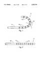
- FIG. 1is a side view of a tubular member in accordance with this invention, in a relaxed state.
- FIG. 2is a side view of the tubular member of FIG. 1 in the compressed state.
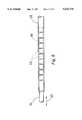
- FIG. 3is a side view of a second tubular member of this invention, in a relaxed state.
- FIG. 4is a side view of the tubular member of FIG. 3 in the compressed state.
- FIG. 5is a side view of a section of a composite catheter in accordance with this invention, with a portion of the tubular member shown in dashed lines.
- FIG. 6is a cross section of a human aorta with a composite catheter of this invention inserted through the aorta to the right coronary artery.
- FIG. 7is the same view as FIG. 6, with the composite catheter in a configuration resulting from compression of the tubular member.
- FIG. 8is a cross section of a human aorta with a second composite catheter of this invention inserted through the aorta to the right coronary artery.
- FIG. 9is the same view as FIG. 8, with the composite catheter in a configuration resulting from compression of the tubular member.
- FIG. 10is a cross section of a human aorta with a third composite catheter of this invention inserted through the aorta to the right coronary artery.
- FIG. 11is the same view as FIG. 10, with the composite catheter in a configuration resulting from compression of the tubular member.
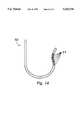
- FIG. 12is a side view of a catheter body in accordance with this invention, without a tubular member inside.
- FIG. 13is the same view as FIG. 12, except that a tubular member has been placed inside the catheter body and held in a relaxed or extended condition.
- FIG. 14is the same view as FIG. 13, except that the tubular member has been compressed.
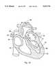
- FIG. 15is a from view of a human heart in cross section, with a composite catheter in accordance with this invention placed inside the right ventricle and a mapping and ablation catheter passing through the guide catheter.
- FIG. 16is a front view of a human heart in cross section, with a composite catheter in accordance with this invention placed inside the left ventricle and a mapping and ablation catheter passing through the guide catheter.
- FIGS. 1 and 2illustrate a single tubular member 11 prior to insertion in, or fixation to, a catheter body.
- the distal region of the tubular memberis shown in both Figures, in a partially extended condition in FIG. 1 and in a compressed condition in FIG. 2.
- the tubular memberis made up of a shaft 12 and a series of short cylindrical segments 13 separated by connecting segments 14.
- the shaft 12 and cylindrical segments 13are hollow cylinders or cylindrical sections, and are relatively rigid, with sufficient rigidity to resist axial collapse under an axially directed force or bending under a lateral torque.
- the connecting segments 14are also cylindrical segments but are flexible, collapsing under an axial force or bending under a lateral torque.
- the rigid cylindrical segments 13When the tubular member 11 is compressed as in FIG. 2, the rigid cylindrical segments 13 are pushed together, causing the connecting segments 14 to buckle and bunch up as shown.
- the stacked rigid segments 13form a straight length of relatively rigid tubing.
- the distal region of the tubular member 11loses its rigidity and can bend as indicated by the arrows 15.
- the tubular memberis shown curved to one side to indicate its flexibility.
- FIGS. 3 and 4illustrate a tubular member 20 which forms a curve when compressed.
- the rigid segments 21are sections of a torus, and when stacked against each other, compressing the flexible connecting sections 22 in between, they form a curved tube, as shown in FIG. 4 which shows the tubular member compressed.
- the tubular memberWhen not compressed, the tubular member is flexible, and can be straight as shown in FIG. 3, curved to a greater or lesser degree than shown in FIG. 4, or in a different direction.
- the flexibility in the non-compressed conditionis indicated by the arrows 23 in FIG. 3.
- the tubular member 11 of FIGS. 1 and 2is shown inside a catheter body 25 in FIG. 5.
- the tubular member 11, much of which is shown in dashed lines,is shown in the compressed condition in this drawing, causing the rigid segments 13 to align into a straight tube, and thereby cause the catheter body 21 to straighten as well.
- the rigid segment at the distal end 26is bonded to the inside surface of the catheter body 21. The remaining rigid segments can then be forced against each other or separated from each other by simply moving the tubular member in the direction indicated by the arrows 27.
- FIGS. 6 and 7illustrate a catheter of the invention having a shape of the Amplatz Right type 30.
- the catheteris inserted in an aorta, passing through the aortic arch 31 to the aortic root 32, in an attempt to place the distal end 33 of the catheter inside the entry to the right coronary artery 34.
- the catheteris a composite of the catheter body and tubular member as discussed above.
- the tubular memberis relaxed, and the section 35 of the catheter body in which the separated rigid sections of the tubular member reside is curved to follow the shape memory of the catheter body 36, since the portion of the tubular member formed by the separated tubular sections is flexible.
- the distal tip 33is not properly placed, however, being too high to enter the coronary artery 34.
- FIG. 7where the section 35 of the catheter body in which the separated rigid sections of the tubular member reside is shortened and partially straightened by forcing the rigid sections against each other. This is done by forcing the tubular member inward from the proximal end while its distal end is affixed to the inside wall of the catheter body.
- the result of the change in shapeis a more gentle curve in the distal region of the catheter body, aligning the distal tip 33 with the artery 34.
- FIGS. 8 and 9illustrate a catheter of the Judkins Right type 40.
- the catheterpasses through the aortic arch 31, and its distal tip 41 enters the right coronary artery 34.
- this catheteris a composite of the catheter body and tubular member.
- the tubular memberis relaxed and its rigid segments separated.
- the individual rigid segmentsare slightly curved, as in FIGS. 3 and 4, while the shape memory of the catheter body in the vicinity of these segments is straight.
- the shape of the section 42 of the catheter body immediately adjacent to these rigid segmentsis approximately straight since it is governed by the shape memory. The result is that, while the distal tip 41 is properly placed inside the right coronary artery 34, the remainder of the composite catheter is not anchored anywhere other than at the top of the aortic arch 31.
- FIGS. 10 and 11illustrate a composite catheter 46 that has a Judkins Right shape when the tubular member is compressed and an Amplatz Right shape when the tubular member is relaxed.
- the individual rigid segments of the tubular memberare straight, unlike those in the composite catheter of FIGS. 8 and 9.
- the rigid segmentsform a substantially straight line like the corresponding portion of the conventional Judkins shape.
- the section 47 of the catheter body where the rigid segments of the tubular member residehas a curved shape memory, which it assumes in the relaxed configuration of FIG. 10, but which is changed into the relatively straight Judkins shape in FIG. 11.
- the tubular membercan force the catheter body to deviate from its shape memory.
- the degree of deviation caused by an extended tubular memberwill vary depending on the lengths of the rigid segments and the connecting segments, longer rigid segments and shorter connecting segments producing greater deviation.
- the composite cathetercan thus have three distinct shapes or degrees of curvature --one with the tubular member removed entirely from the catheter body, a second with the tubular member inserted in the catheter body but the connecting segments fully extended, and a third with the tubular member inserted and the connecting segments collapsed so that the rigid segments are compressed against each other.
- An example of a composite catheter 50 with this characteristicis shown in FIGS.
- the rigid segments 51 of the tubular memberare straight while the shape memory of the catheter body is curved. Accordingly, the tubular member reduces the curvature of the catheter body to successive degrees, as represented by the Figures in the order shown. The opposite effect is readily achieved by a catheter body with relatively straight shape memory and a tubular member with curved rigid segments.
- FIGS. 15 and 16Each of these Figures shows a cross section of the human heart, showing the right atrium 60, left atrium 61, right ventricle 62, left ventricle 63, aortic arch 64, ascending aorta 65 and superior vena cava 66.
- FIG. 15illustrates mapping and ablation in the right ventricle 62 by the use of a mapping and ablation catheter 70 directed to the appropriate chamber wall by a composite guide catheter 71 in accordance with this invention.
- Manipulation of the tubular member (not shown) inside the guide catheterpermits the operator to move the guide catheter in the direction of the arrows 72, to adjust the pressure of the ablation tip 73 against the chamber wall 74.
- FIG. 16illustrates mapping and ablation in the left ventricle 63, again by the use of a mapping and ablation catheter 76 directed by a composite guide catheter 77 in accordance with this invention.
- Manipulation of the tubular memberpermits the operator to adjust the position of the guide catheter in the directions indicated by the dashed lines to reach a range of locations on the chamber wall 78 and to apply sufficient pressure to maintain contact.
- the tipis actuated and the procedure is performed.
- the rigid sections in any single tubular membercan be identical in all respects or they can vary such as by differing in length, curvature or rigidity. Specialized shapes of highly controlled curvature and specialized shape changes can be obtained by a appropriate combination of rigid sections of differing dimensions or construction.
- the lengths of the collapsible connecting sections in a single tubular membercan likewise vary to achieve a similar effect.
- the rigid sectionsare preferably rings ranging from about 0.1 cm to about 1.0 cm in length, and most preferably about 0.2 cm to about 0.3 cm.
- the collapsible connecting segmentsare generally of a similar size.
- the rigid segmentsmay be formed of metals or metal alloys, although hard plastics or composites can also be used.
- the connecting elementsmay be thin-wall Teflon tubing, or any other compressible or collapsible material.
- the number of rigid segmentswill depend on the type and degree of curvature change, but in general, there will be at least four such segments, preferably ten to thirty.
- the uncurved length of the catheter bodywill generally range from about 50 cm to about 150 cm, preferably from about 90 cm to about 120 cm.
- the catheter bodywill have a lumen with a diameter of from about 1.75 mm to about 3.0 mm, preferably from about 2.0 mm to about 2.75 mm.
- the tubular memberwill be small enough to fit within the lumen of the catheter body with a sufficiently loose fit to be moved longitudinally inside the lumen, but large enough so that the lumen of the tubular member itself can accommodate a working catheter, or two or more if necessary.
- the shape memory of the catheter body when not under the influence of the tubular membermay be inherent in the catheter body itself, imposed by molding, tempering, or alloying techniques or other methods known to those skilled in the art.
- the shape memorymay be imparted and maintained by one or more spring rods (not shown in the drawings) embedded in the wall of the catheter body.
- the spring rodswill be straight or curved as needed, and will be resilient enough that their shapes will be modified by the rigid segments of the tubular member yet capable of resuming the curvature when the rigid segments are removed.
- Manipulation of the tubular memberis performed at the proximal end of the catheter, outside the patient's body. Manipulation is readily performed by hand, with the operator assisted by visualization of the distal tip of the catheter. Visualization may be achieved by conventional means. Fluoroscopy, a common visualization technique for catheters, is one example.
- the movement and securement of the tubular member relative to the catheter bodycan be achieved at the proximal end by simple mechanical devices. Examples are a threaded knob, a ratchet-type mechanism, or various kinds of toothed or locking mechanisms which can be manipulated by hand. Other examples will be readily apparent to those skilled in the art.
- One specific exampleis a toothed track on a stationary member to which the catheter body is mounted, and a spring-loaded catch on a mobile member to which the tubular member is mounted, the catch mounted through a pivot to a toothed wheel.
- the wheelWhen the wheel is pushed by the user's thumb to engage the track, the catch is lifted away from engagement with the track. Turning of the wheel while pressing it against the track by the user's thumb moves the mobile member relative to the stationary member, and release of the wheel causes the catch to engage the track, locking the members relative to each other.
- Many other mechanisms with a similar ease of manipulationcan be substituted.
Landscapes
- Health & Medical Sciences (AREA)
- Life Sciences & Earth Sciences (AREA)
- Biophysics (AREA)
- Pulmonology (AREA)
- Engineering & Computer Science (AREA)
- Anesthesiology (AREA)
- Biomedical Technology (AREA)
- Heart & Thoracic Surgery (AREA)
- Hematology (AREA)
- Animal Behavior & Ethology (AREA)
- General Health & Medical Sciences (AREA)
- Public Health (AREA)
- Veterinary Medicine (AREA)
- Media Introduction/Drainage Providing Device (AREA)
Abstract
Description
Claims (15)
Priority Applications (3)
| Application Number | Priority Date | Filing Date | Title |
|---|---|---|---|
| US08/541,453US5632734A (en) | 1995-10-10 | 1995-10-10 | Catheter shape control by collapsible inner tubular member |
| PCT/US1996/015220WO1997010749A1 (en) | 1995-09-22 | 1996-09-20 | Catheter shape control by collapsible inner tubular member |
| AU71164/96AAU7116496A (en) | 1995-09-22 | 1996-09-20 | Catheter shape control by collapsible inner tubular member |
Applications Claiming Priority (1)
| Application Number | Priority Date | Filing Date | Title |
|---|---|---|---|
| US08/541,453US5632734A (en) | 1995-10-10 | 1995-10-10 | Catheter shape control by collapsible inner tubular member |
Publications (1)
| Publication Number | Publication Date |
|---|---|
| US5632734Atrue US5632734A (en) | 1997-05-27 |
Family
ID=24159662
Family Applications (1)
| Application Number | Title | Priority Date | Filing Date |
|---|---|---|---|
| US08/541,453Expired - LifetimeUS5632734A (en) | 1995-09-22 | 1995-10-10 | Catheter shape control by collapsible inner tubular member |
Country Status (1)
| Country | Link |
|---|---|
| US (1) | US5632734A (en) |
Cited By (72)
| Publication number | Priority date | Publication date | Assignee | Title |
|---|---|---|---|---|
| US5730741A (en)* | 1997-02-07 | 1998-03-24 | Eclipse Surgical Technologies, Inc. | Guided spiral catheter |
| US5882346A (en)* | 1996-07-15 | 1999-03-16 | Cardiac Pathways Corporation | Shapable catheter using exchangeable core and method of use |
| US5908447A (en)* | 1998-02-06 | 1999-06-01 | Intermedics Inc. | Breakaway structure for body implantable medical device |
| US5913852A (en)* | 1995-07-21 | 1999-06-22 | Nemours Foundation | Drain cannula |
| US6002969A (en)* | 1998-08-05 | 1999-12-14 | Intermedics Inc. | Cardiac lead with shape-memory structure |
| US6002955A (en)* | 1996-11-08 | 1999-12-14 | Medtronic, Inc. | Stabilized electrophysiology catheter and method for use |
| US6024764A (en)* | 1997-08-19 | 2000-02-15 | Intermedics, Inc. | Apparatus for imparting physician-determined shapes to implantable tubular devices |
| US6068621A (en)* | 1998-11-20 | 2000-05-30 | Embol X, Inc. | Articulating cannula |
| US6083216A (en)* | 1999-01-05 | 2000-07-04 | Intermedics Inc. | Bent cardiac lead with shape memory torque coil |
| US6119731A (en)* | 1984-02-13 | 2000-09-19 | Excell Corporation | Hollow plastic product |
| US6251104B1 (en) | 1995-05-10 | 2001-06-26 | Eclipse Surgical Technologies, Inc. | Guiding catheter system for ablating heart tissue |
| US6319454B1 (en) | 1984-02-13 | 2001-11-20 | Excell Corporation | Method and apparatus for manufacturing a hollow plastic product |
| US6398791B1 (en) | 1999-06-11 | 2002-06-04 | Scimed Life Systems Inc | Variable composite sheath with interrupted sections |
| US6398266B1 (en) | 1999-09-22 | 2002-06-04 | Ballard Medical Products | Collapse resistant popoid connector |
| USD466607S1 (en) | 2001-08-27 | 2002-12-03 | Kimberly-Clark Worldwide, Inc. | Flexible connector |
| US20020188278A1 (en)* | 2001-06-07 | 2002-12-12 | Bruce Tockman | Method and apparatus for an adjustable shape guide catheter |
| USD473941S1 (en) | 2001-08-27 | 2003-04-29 | Kimberly-Clark Worldwide, Inc. | Flexible connecting device |
| USD476731S1 (en) | 2001-08-27 | 2003-07-01 | Kimberly-Clark Worldwide, Inc. | Bendable connector |
| US20030144657A1 (en)* | 2002-01-28 | 2003-07-31 | Cardiac Pacemakers, Inc. | Inner and outer telescoping catheter delivery system |
| US20030145122A1 (en)* | 2002-01-30 | 2003-07-31 | International Business Machines Corporation | Apparatus and method of allowing multiple partitions of a partitioned computer system to use a single network adapter |
| US6620202B2 (en) | 2001-10-16 | 2003-09-16 | Scimed Life Systems, Inc. | Medical stent with variable coil and related methods |
| US20040013646A1 (en)* | 1994-05-11 | 2004-01-22 | Yeda Research And Development Co. Ltd. | Modulator of TNF/NGF superfamily receptors and soluble oligomeric TNF/NGF superfamily receptors |
| USD486909S1 (en) | 2001-08-27 | 2004-02-17 | Kimberly-Clark Worldwide, Inc. | Bendable connecting device |
| US6719804B2 (en) | 2001-04-02 | 2004-04-13 | Scimed Life Systems, Inc. | Medical stent and related methods |
| US20050004515A1 (en)* | 2002-11-15 | 2005-01-06 | Hart Charles C. | Steerable kink resistant sheath |
| US20060015096A1 (en)* | 2004-05-28 | 2006-01-19 | Hauck John A | Radio frequency ablation servo catheter and method |
| US20060089692A1 (en)* | 2004-10-21 | 2006-04-27 | Medtronic, Inc. | Implantable medical lead with stylet guide tube |
| US20060089695A1 (en)* | 2004-10-21 | 2006-04-27 | Medtronic, Inc. | Implantable medical lead with helical reinforcement |
| US20060089691A1 (en)* | 2004-10-21 | 2006-04-27 | Medtronic, Inc. | Implantable medical lead with axially oriented coiled wire conductors |
| US20060089697A1 (en)* | 2004-10-21 | 2006-04-27 | Medtronic, Inc. | Implantable medical lead |
| US20060089696A1 (en)* | 2004-10-21 | 2006-04-27 | Medtronic, Inc. | Implantable medical lead with reinforced outer jacket |
| US20060129132A1 (en)* | 2001-12-11 | 2006-06-15 | Cardiac Pacemakers, Inc. | Deflectable telescoping guide catheter |
| US7178521B2 (en) | 2004-01-09 | 2007-02-20 | King Systems Corporation | Adjustable length breathing circuit |
| US20070185404A1 (en)* | 2004-05-28 | 2007-08-09 | Hauck John A | Robotic surgical system and method for diagnostic data mapping |
| US20070181139A1 (en)* | 2004-05-28 | 2007-08-09 | Hauck John A | Robotic surgical system with contact sensing feature |
| US20070185486A1 (en)* | 2004-05-28 | 2007-08-09 | Hauck John A | Robotic surgical system |
| US20070185485A1 (en)* | 2004-05-28 | 2007-08-09 | Hauck John A | Robotic surgical system and method for automated creation of ablation lesions |
| US20070198008A1 (en)* | 2004-05-28 | 2007-08-23 | Hauck John A | Robotic surgical system and method for automated therapy delivery |
| US20070208300A1 (en)* | 2006-03-01 | 2007-09-06 | Applied Medical Resources Corporation | Gas insufflation and suction/irrigation tubing |
| US20070215268A1 (en)* | 2002-11-15 | 2007-09-20 | Applied Medical Resources Corporation | Method of making medical tubing having variable characteristics using thermal winding |
| US20070225558A1 (en)* | 2004-05-28 | 2007-09-27 | Hauck John A | Robotic surgical system and method for surface modeling |
| US20080033284A1 (en)* | 2005-05-27 | 2008-02-07 | Hauck John A | Robotically controlled catheter and method of its calibration |
| US20080125696A1 (en)* | 2006-08-21 | 2008-05-29 | Tycohealthcare Group Lp | Adjustable aspiration device and method of making |
| US20090143844A1 (en)* | 2007-11-29 | 2009-06-04 | Gaymar Industries, Inc. | Hose management for convective devices |
| US20090177138A1 (en)* | 2007-11-07 | 2009-07-09 | Brown Reay H | Shunt Device for Glaucoma Treatment |
| US20100114114A1 (en)* | 2002-08-23 | 2010-05-06 | Bruce Tockman | Coronary vein navigator |
| US20100286688A1 (en)* | 2009-05-08 | 2010-11-11 | Hughett Sr James David | Flexible ablation clamp |
| US20110005661A1 (en)* | 2004-01-28 | 2011-01-13 | Applied Medical Resources Corporation | Medical Tubing Having Variable Characteristics and Method of Making Same |
| US20110276084A1 (en)* | 2010-05-07 | 2011-11-10 | Ethicon Endo-Surgery, Inc. | Laparoscopic devices with flexible actuation mechanisms |
| US8398672B2 (en) | 2003-11-12 | 2013-03-19 | Nitinol Devices And Components, Inc. | Method for anchoring a medical device |
| US20140236120A1 (en)* | 2013-02-19 | 2014-08-21 | Leo Lee Tsai | Adjustable stiffness catheter |
| US9233225B2 (en) | 2012-11-10 | 2016-01-12 | Curvo Medical, Inc. | Coaxial bi-directional catheter |
| US9333001B2 (en) | 2009-10-08 | 2016-05-10 | Ethicon Endo-Surgery, Inc. | Articulable laparoscopic instrument |
| US9468426B2 (en) | 2010-05-07 | 2016-10-18 | Ethicon Endo-Surgery, Inc. | Compound angle laparoscopic methods and devices |
| US9549666B2 (en) | 2012-11-10 | 2017-01-24 | Curvo Medical, Inc. | Coaxial micro-endoscope |
| US9649211B2 (en) | 2009-11-04 | 2017-05-16 | Confluent Medical Technologies, Inc. | Alternating circumferential bridge stent design and methods for use thereof |
| US10092427B2 (en) | 2009-11-04 | 2018-10-09 | Confluent Medical Technologies, Inc. | Alternating circumferential bridge stent design and methods for use thereof |
| KR20210072847A (en)* | 2019-12-09 | 2021-06-18 | 한국과학기술연구원 | System and method for controling needle with variable stiffness structure |
| US11122971B2 (en) | 2016-08-18 | 2021-09-21 | Neptune Medical Inc. | Device and method for enhanced visualization of the small intestine |
| US11135398B2 (en) | 2018-07-19 | 2021-10-05 | Neptune Medical Inc. | Dynamically rigidizing composite medical structures |
| US11219351B2 (en) | 2015-09-03 | 2022-01-11 | Neptune Medical Inc. | Device for endoscopic advancement through the small intestine |
| CN115530967A (en)* | 2021-06-29 | 2022-12-30 | 上海微创电生理医疗科技股份有限公司 | Medical catheter |
| US11744443B2 (en) | 2020-03-30 | 2023-09-05 | Neptune Medical Inc. | Layered walls for rigidizing devices |
| US11793392B2 (en) | 2019-04-17 | 2023-10-24 | Neptune Medical Inc. | External working channels |
| US11872357B2 (en) | 2020-11-09 | 2024-01-16 | Agile Devices, Inc. | Devices for steering catheters |
| US11937778B2 (en) | 2022-04-27 | 2024-03-26 | Neptune Medical Inc. | Apparatuses and methods for determining if an endoscope is contaminated |
| US20240131307A1 (en)* | 2019-10-23 | 2024-04-25 | Imam Abdulrahman Bin Faisal University | Spring-tensioned articulable catheter |
| US12059128B2 (en) | 2018-05-31 | 2024-08-13 | Neptune Medical Inc. | Device and method for enhanced visualization of the small intestine |
| US12121677B2 (en) | 2021-01-29 | 2024-10-22 | Neptune Medical Inc. | Devices and methods to prevent inadvertent motion of dynamically rigidizing apparatuses |
| US12295550B2 (en) | 2017-07-20 | 2025-05-13 | Neptune Medical Inc. | Dynamically rigidizing overtube |
| US12329473B2 (en) | 2019-04-17 | 2025-06-17 | Neptune Medical Inc. | Dynamically rigidizing composite medical structures |
| US12330292B2 (en) | 2023-09-28 | 2025-06-17 | Neptune Medical Inc. | Telescoping robot |
Citations (29)
| Publication number | Priority date | Publication date | Assignee | Title |
|---|---|---|---|---|
| US4033331A (en)* | 1975-07-17 | 1977-07-05 | Guss Stephen B | Cardiac catheter and method of using same |
| US4323071A (en)* | 1978-04-24 | 1982-04-06 | Advanced Catheter Systems, Inc. | Vascular guiding catheter assembly and vascular dilating catheter assembly and a combination thereof and methods of making the same |
| US4432349A (en)* | 1979-04-03 | 1984-02-21 | Fuji Photo Optical Co., Ltd. | Articulated tube structure for use in an endoscope |
| US4516972A (en)* | 1982-01-28 | 1985-05-14 | Advanced Cardiovascular Systems, Inc. | Guiding catheter and method of manufacture |
| US4790331A (en)* | 1986-12-02 | 1988-12-13 | Sherwood Medical Company | Method for placement of catheter in a blood vessel |
| US4852564A (en)* | 1984-06-28 | 1989-08-01 | Sheridan Catheter Corp. | Flexible connectors for medico-surgical tubes |
| US4873965A (en)* | 1987-07-31 | 1989-10-17 | Guido Danieli | Flexible endoscope |
| US4898577A (en)* | 1988-09-28 | 1990-02-06 | Advanced Cardiovascular Systems, Inc. | Guiding cathether with controllable distal tip |
| US4925445A (en)* | 1983-09-16 | 1990-05-15 | Fuji Terumo Co., Ltd. | Guide wire for catheter |
| US4935017A (en)* | 1988-04-29 | 1990-06-19 | C. R. Bard, Inc. | Variable shaped catheter system and method for catheterization |
| US4960411A (en)* | 1984-09-18 | 1990-10-02 | Medtronic Versaflex, Inc. | Low profile sterrable soft-tip catheter |
| US5030204A (en)* | 1988-09-28 | 1991-07-09 | Advanced Cardiovascular Systems, Inc. | Guiding catheter with controllable distal tip |
| US5098412A (en)* | 1989-11-04 | 1992-03-24 | Shiu Man F | Support system for catheter |
| US5109830A (en)* | 1990-04-10 | 1992-05-05 | Candela Laser Corporation | Apparatus for navigation of body cavities |
| US5114414A (en)* | 1984-09-18 | 1992-05-19 | Medtronic, Inc. | Low profile steerable catheter |
| US5120323A (en)* | 1990-01-12 | 1992-06-09 | Schneider (Usa) Inc. | Telescoping guide catheter system |
| US5131406A (en)* | 1989-09-20 | 1992-07-21 | Martin Kaltenbach | Guide for introduction of catheters into blood vessels and the like |
| US5203280A (en)* | 1991-12-23 | 1993-04-20 | Dec International, Inc. | Rapid exit herringbone stall |
| US5211183A (en)* | 1987-05-13 | 1993-05-18 | Wilson Bruce C | Steerable memory alloy guide wires |
| US5231989A (en)* | 1991-02-15 | 1993-08-03 | Raychem Corporation | Steerable cannula |
| US5290229A (en)* | 1991-07-15 | 1994-03-01 | Paskar Larry D | Transformable catheter and method |
| US5304131A (en)* | 1991-07-15 | 1994-04-19 | Paskar Larry D | Catheter |
| US5308342A (en)* | 1991-08-07 | 1994-05-03 | Target Therapeutics, Inc. | Variable stiffness catheter |
| US5391147A (en)* | 1992-12-01 | 1995-02-21 | Cardiac Pathways Corporation | Steerable catheter with adjustable bend location and/or radius and method |
| US5448989A (en)* | 1993-02-22 | 1995-09-12 | Richard Wolf Gmbh | Medical instrument shaft capable of positive and non-positive linking of segments |
| US5496294A (en)* | 1994-07-08 | 1996-03-05 | Target Therapeutics, Inc. | Catheter with kink-resistant distal tip |
| US5549581A (en)* | 1993-08-13 | 1996-08-27 | Daig Corporation | Coronary sinus catheter |
| US5569221A (en)* | 1994-07-07 | 1996-10-29 | Ep Technologies, Inc. | Catheter component bond and method |
| US5569218A (en)* | 1994-02-14 | 1996-10-29 | Scimed Life Systems, Inc. | Elastic guide catheter transition element |
- 1995
- 1995-10-10USUS08/541,453patent/US5632734A/ennot_activeExpired - Lifetime
Patent Citations (31)
| Publication number | Priority date | Publication date | Assignee | Title |
|---|---|---|---|---|
| US4033331A (en)* | 1975-07-17 | 1977-07-05 | Guss Stephen B | Cardiac catheter and method of using same |
| US4323071A (en)* | 1978-04-24 | 1982-04-06 | Advanced Catheter Systems, Inc. | Vascular guiding catheter assembly and vascular dilating catheter assembly and a combination thereof and methods of making the same |
| US4323071B1 (en)* | 1978-04-24 | 1990-05-29 | Advanced Cardiovascular System | |
| US4432349A (en)* | 1979-04-03 | 1984-02-21 | Fuji Photo Optical Co., Ltd. | Articulated tube structure for use in an endoscope |
| US4516972A (en)* | 1982-01-28 | 1985-05-14 | Advanced Cardiovascular Systems, Inc. | Guiding catheter and method of manufacture |
| US4925445A (en)* | 1983-09-16 | 1990-05-15 | Fuji Terumo Co., Ltd. | Guide wire for catheter |
| US4852564A (en)* | 1984-06-28 | 1989-08-01 | Sheridan Catheter Corp. | Flexible connectors for medico-surgical tubes |
| US5114414A (en)* | 1984-09-18 | 1992-05-19 | Medtronic, Inc. | Low profile steerable catheter |
| US4960411A (en)* | 1984-09-18 | 1990-10-02 | Medtronic Versaflex, Inc. | Low profile sterrable soft-tip catheter |
| US4790331A (en)* | 1986-12-02 | 1988-12-13 | Sherwood Medical Company | Method for placement of catheter in a blood vessel |
| US5211183A (en)* | 1987-05-13 | 1993-05-18 | Wilson Bruce C | Steerable memory alloy guide wires |
| US4873965A (en)* | 1987-07-31 | 1989-10-17 | Guido Danieli | Flexible endoscope |
| US4935017A (en)* | 1988-04-29 | 1990-06-19 | C. R. Bard, Inc. | Variable shaped catheter system and method for catheterization |
| US5267982A (en)* | 1988-04-29 | 1993-12-07 | C. R. Bard, Inc. | Variable shaped catheter system and method for catheterization |
| US4898577A (en)* | 1988-09-28 | 1990-02-06 | Advanced Cardiovascular Systems, Inc. | Guiding cathether with controllable distal tip |
| US5030204A (en)* | 1988-09-28 | 1991-07-09 | Advanced Cardiovascular Systems, Inc. | Guiding catheter with controllable distal tip |
| US5131406A (en)* | 1989-09-20 | 1992-07-21 | Martin Kaltenbach | Guide for introduction of catheters into blood vessels and the like |
| US5098412A (en)* | 1989-11-04 | 1992-03-24 | Shiu Man F | Support system for catheter |
| US5120323A (en)* | 1990-01-12 | 1992-06-09 | Schneider (Usa) Inc. | Telescoping guide catheter system |
| US5109830A (en)* | 1990-04-10 | 1992-05-05 | Candela Laser Corporation | Apparatus for navigation of body cavities |
| US5231989A (en)* | 1991-02-15 | 1993-08-03 | Raychem Corporation | Steerable cannula |
| US5304131A (en)* | 1991-07-15 | 1994-04-19 | Paskar Larry D | Catheter |
| US5290229A (en)* | 1991-07-15 | 1994-03-01 | Paskar Larry D | Transformable catheter and method |
| US5308342A (en)* | 1991-08-07 | 1994-05-03 | Target Therapeutics, Inc. | Variable stiffness catheter |
| US5203280A (en)* | 1991-12-23 | 1993-04-20 | Dec International, Inc. | Rapid exit herringbone stall |
| US5391147A (en)* | 1992-12-01 | 1995-02-21 | Cardiac Pathways Corporation | Steerable catheter with adjustable bend location and/or radius and method |
| US5448989A (en)* | 1993-02-22 | 1995-09-12 | Richard Wolf Gmbh | Medical instrument shaft capable of positive and non-positive linking of segments |
| US5549581A (en)* | 1993-08-13 | 1996-08-27 | Daig Corporation | Coronary sinus catheter |
| US5569218A (en)* | 1994-02-14 | 1996-10-29 | Scimed Life Systems, Inc. | Elastic guide catheter transition element |
| US5569221A (en)* | 1994-07-07 | 1996-10-29 | Ep Technologies, Inc. | Catheter component bond and method |
| US5496294A (en)* | 1994-07-08 | 1996-03-05 | Target Therapeutics, Inc. | Catheter with kink-resistant distal tip |
Cited By (145)
| Publication number | Priority date | Publication date | Assignee | Title |
|---|---|---|---|---|
| US6319454B1 (en) | 1984-02-13 | 2001-11-20 | Excell Corporation | Method and apparatus for manufacturing a hollow plastic product |
| US6119731A (en)* | 1984-02-13 | 2000-09-19 | Excell Corporation | Hollow plastic product |
| US20040013646A1 (en)* | 1994-05-11 | 2004-01-22 | Yeda Research And Development Co. Ltd. | Modulator of TNF/NGF superfamily receptors and soluble oligomeric TNF/NGF superfamily receptors |
| US7186682B2 (en) | 1994-05-11 | 2007-03-06 | Yeda Research And Development Co. Ltd. | Modulator of TNF/NGF superfamily receptors and soluble oligomeric TNF/NGF superfamily receptors |
| US20070232520A1 (en)* | 1994-05-11 | 2007-10-04 | Yeda Research And Development Co., Ltd. | Modulator of tnf/ngf superfamily receptors and soluble oligomeric tnf/ngf superfamily receptors |
| US6251104B1 (en) | 1995-05-10 | 2001-06-26 | Eclipse Surgical Technologies, Inc. | Guiding catheter system for ablating heart tissue |
| US6830568B1 (en) | 1995-05-10 | 2004-12-14 | Randy J. Kesten | Guiding catheter system for ablating heart tissue |
| US6592575B1 (en) | 1995-05-10 | 2003-07-15 | Randy J. Kesten | Guiding catheter system for ablating heart tissue |
| US5913852A (en)* | 1995-07-21 | 1999-06-22 | Nemours Foundation | Drain cannula |
| US5882346A (en)* | 1996-07-15 | 1999-03-16 | Cardiac Pathways Corporation | Shapable catheter using exchangeable core and method of use |
| US6002955A (en)* | 1996-11-08 | 1999-12-14 | Medtronic, Inc. | Stabilized electrophysiology catheter and method for use |
| US5730741A (en)* | 1997-02-07 | 1998-03-24 | Eclipse Surgical Technologies, Inc. | Guided spiral catheter |
| US6024764A (en)* | 1997-08-19 | 2000-02-15 | Intermedics, Inc. | Apparatus for imparting physician-determined shapes to implantable tubular devices |
| US5908447A (en)* | 1998-02-06 | 1999-06-01 | Intermedics Inc. | Breakaway structure for body implantable medical device |
| US6002969A (en)* | 1998-08-05 | 1999-12-14 | Intermedics Inc. | Cardiac lead with shape-memory structure |
| US6068621A (en)* | 1998-11-20 | 2000-05-30 | Embol X, Inc. | Articulating cannula |
| US6083216A (en)* | 1999-01-05 | 2000-07-04 | Intermedics Inc. | Bent cardiac lead with shape memory torque coil |
| US6398791B1 (en) | 1999-06-11 | 2002-06-04 | Scimed Life Systems Inc | Variable composite sheath with interrupted sections |
| US7708745B2 (en) | 1999-06-11 | 2010-05-04 | Boston Scientific Scimed, Inc. | Variable composite sheath with interrupted sections |
| US20050277949A1 (en)* | 1999-06-11 | 2005-12-15 | Boston Scientific Scimed, Inc. | Variable composite sheath with interrupted sections |
| US6939353B2 (en) | 1999-06-11 | 2005-09-06 | Boston Scientific Scimed. Inc. | Variable composite sheath with interrupted sections |
| US6398266B1 (en) | 1999-09-22 | 2002-06-04 | Ballard Medical Products | Collapse resistant popoid connector |
| US6719804B2 (en) | 2001-04-02 | 2004-04-13 | Scimed Life Systems, Inc. | Medical stent and related methods |
| US7951206B2 (en) | 2001-04-02 | 2011-05-31 | Boston Scientific Scimed, Inc. | Medical stent |
| US7291180B2 (en) | 2001-04-02 | 2007-11-06 | Boston Scientific Scimed, Inc. | Medical stent and related methods |
| US7674245B2 (en)* | 2001-06-07 | 2010-03-09 | Cardiac Pacemakers, Inc. | Method and apparatus for an adjustable shape guide catheter |
| US20050159725A1 (en)* | 2001-06-07 | 2005-07-21 | Cardiac Pacemakers, Inc. | Method for manipulating an adjustable shape guide catheter |
| US20020188278A1 (en)* | 2001-06-07 | 2002-12-12 | Bruce Tockman | Method and apparatus for an adjustable shape guide catheter |
| US7875018B2 (en)* | 2001-06-07 | 2011-01-25 | Cardiac Pacemakers, Inc. | Method for manipulating an adjustable shape guide catheter |
| USD466607S1 (en) | 2001-08-27 | 2002-12-03 | Kimberly-Clark Worldwide, Inc. | Flexible connector |
| USD486909S1 (en) | 2001-08-27 | 2004-02-17 | Kimberly-Clark Worldwide, Inc. | Bendable connecting device |
| USD473941S1 (en) | 2001-08-27 | 2003-04-29 | Kimberly-Clark Worldwide, Inc. | Flexible connecting device |
| USD476731S1 (en) | 2001-08-27 | 2003-07-01 | Kimberly-Clark Worldwide, Inc. | Bendable connector |
| US6620202B2 (en) | 2001-10-16 | 2003-09-16 | Scimed Life Systems, Inc. | Medical stent with variable coil and related methods |
| US7037345B2 (en) | 2001-10-16 | 2006-05-02 | Boston Scientific Scimed, Inc. | Medical stent with variable coil and related methods |
| US20060129132A1 (en)* | 2001-12-11 | 2006-06-15 | Cardiac Pacemakers, Inc. | Deflectable telescoping guide catheter |
| US7717899B2 (en) | 2002-01-28 | 2010-05-18 | Cardiac Pacemakers, Inc. | Inner and outer telescoping catheter delivery system |
| US8753312B2 (en) | 2002-01-28 | 2014-06-17 | Cardiac Pacemakers, Inc. | Inner and outer telescoping catheter delivery system |
| US8401673B2 (en) | 2002-01-28 | 2013-03-19 | Cardiac Pacemakers, Inc. | Inner and outer telescoping catheter delivery system and method |
| US20030144657A1 (en)* | 2002-01-28 | 2003-07-31 | Cardiac Pacemakers, Inc. | Inner and outer telescoping catheter delivery system |
| US20030145122A1 (en)* | 2002-01-30 | 2003-07-31 | International Business Machines Corporation | Apparatus and method of allowing multiple partitions of a partitioned computer system to use a single network adapter |
| US20100114114A1 (en)* | 2002-08-23 | 2010-05-06 | Bruce Tockman | Coronary vein navigator |
| US7850811B2 (en) | 2002-11-15 | 2010-12-14 | Hart Charles C | Steerable kink-resistant sheath |
| US8529719B2 (en) | 2002-11-15 | 2013-09-10 | Applied Medical Resources Corporation | Method of making medical tubing having variable characteristics using thermal winding |
| US9675378B2 (en) | 2002-11-15 | 2017-06-13 | Applied Medical Resources Corporation | Steerable kink-resistant sheath |
| US20110066105A1 (en)* | 2002-11-15 | 2011-03-17 | Applied Medical Resources Corporation | Steerable kink-resistant sheath |
| US20070215268A1 (en)* | 2002-11-15 | 2007-09-20 | Applied Medical Resources Corporation | Method of making medical tubing having variable characteristics using thermal winding |
| US8721826B2 (en) | 2002-11-15 | 2014-05-13 | Applied Medical Resources Corporation | Steerable kink-resistant sheath |
| US8691035B2 (en) | 2002-11-15 | 2014-04-08 | Applied Medical Resources Corporation | Method of making medical tubing having variable characteristics using thermal winding |
| US20050004515A1 (en)* | 2002-11-15 | 2005-01-06 | Hart Charles C. | Steerable kink resistant sheath |
| US20070277921A1 (en)* | 2002-11-15 | 2007-12-06 | Applied Medical Resources Corporation | Steerable kink-resistant sheath |
| US8398672B2 (en) | 2003-11-12 | 2013-03-19 | Nitinol Devices And Components, Inc. | Method for anchoring a medical device |
| US9283065B2 (en) | 2003-11-12 | 2016-03-15 | Nitinol Devices And Components, Inc. | Medical device anchor and delivery system |
| US8409239B2 (en) | 2003-11-12 | 2013-04-02 | Nitinol Devices And Components, Inc. | Medical device anchor and delivery system |
| US7178521B2 (en) | 2004-01-09 | 2007-02-20 | King Systems Corporation | Adjustable length breathing circuit |
| US10765832B2 (en) | 2004-01-28 | 2020-09-08 | Applied Medical Resources Corporation | Medical tubing having variable characteristics and method of making same |
| US8715441B2 (en) | 2004-01-28 | 2014-05-06 | Applied Medical Resources Corporation | Medical tubing having variable characteristics and method of making same |
| US9987460B2 (en) | 2004-01-28 | 2018-06-05 | Applied Medical Resources Corporation | Medical tubing having variable characteristcs and method of making same |
| US20110005661A1 (en)* | 2004-01-28 | 2011-01-13 | Applied Medical Resources Corporation | Medical Tubing Having Variable Characteristics and Method of Making Same |
| US20070185485A1 (en)* | 2004-05-28 | 2007-08-09 | Hauck John A | Robotic surgical system and method for automated creation of ablation lesions |
| US20070185404A1 (en)* | 2004-05-28 | 2007-08-09 | Hauck John A | Robotic surgical system and method for diagnostic data mapping |
| US20060015096A1 (en)* | 2004-05-28 | 2006-01-19 | Hauck John A | Radio frequency ablation servo catheter and method |
| US9566119B2 (en) | 2004-05-28 | 2017-02-14 | St. Jude Medical, Atrial Fibrillation Division, Inc. | Robotic surgical system and method for automated therapy delivery |
| US9782130B2 (en) | 2004-05-28 | 2017-10-10 | St. Jude Medical, Atrial Fibrillation Division, Inc. | Robotic surgical system |
| US8528565B2 (en) | 2004-05-28 | 2013-09-10 | St. Jude Medical, Atrial Fibrillation Division, Inc. | Robotic surgical system and method for automated therapy delivery |
| US20070225558A1 (en)* | 2004-05-28 | 2007-09-27 | Hauck John A | Robotic surgical system and method for surface modeling |
| US20070185486A1 (en)* | 2004-05-28 | 2007-08-09 | Hauck John A | Robotic surgical system |
| US20070181139A1 (en)* | 2004-05-28 | 2007-08-09 | Hauck John A | Robotic surgical system with contact sensing feature |
| US20070198008A1 (en)* | 2004-05-28 | 2007-08-23 | Hauck John A | Robotic surgical system and method for automated therapy delivery |
| US7974674B2 (en) | 2004-05-28 | 2011-07-05 | St. Jude Medical, Atrial Fibrillation Division, Inc. | Robotic surgical system and method for surface modeling |
| US9204935B2 (en) | 2004-05-28 | 2015-12-08 | St. Jude Medical, Atrial Fibrillation Division, Inc. | Robotic surgical system and method for diagnostic data mapping |
| US8755864B2 (en) | 2004-05-28 | 2014-06-17 | St. Jude Medical, Atrial Fibrillation Division, Inc. | Robotic surgical system and method for diagnostic data mapping |
| US7632265B2 (en) | 2004-05-28 | 2009-12-15 | St. Jude Medical, Atrial Fibrillation Division, Inc. | Radio frequency ablation servo catheter and method |
| US10258285B2 (en) | 2004-05-28 | 2019-04-16 | St. Jude Medical, Atrial Fibrillation Division, Inc. | Robotic surgical system and method for automated creation of ablation lesions |
| US8551084B2 (en) | 2004-05-28 | 2013-10-08 | St. Jude Medical, Atrial Fibrillation Division, Inc. | Radio frequency ablation servo catheter and method |
| US10863945B2 (en) | 2004-05-28 | 2020-12-15 | St. Jude Medical, Atrial Fibrillation Division, Inc. | Robotic surgical system with contact sensing feature |
| US20060089697A1 (en)* | 2004-10-21 | 2006-04-27 | Medtronic, Inc. | Implantable medical lead |
| US20060089692A1 (en)* | 2004-10-21 | 2006-04-27 | Medtronic, Inc. | Implantable medical lead with stylet guide tube |
| US7831311B2 (en)* | 2004-10-21 | 2010-11-09 | Medtronic, Inc. | Reduced axial stiffness implantable medical lead |
| US20060089691A1 (en)* | 2004-10-21 | 2006-04-27 | Medtronic, Inc. | Implantable medical lead with axially oriented coiled wire conductors |
| US20060089696A1 (en)* | 2004-10-21 | 2006-04-27 | Medtronic, Inc. | Implantable medical lead with reinforced outer jacket |
| US20060089695A1 (en)* | 2004-10-21 | 2006-04-27 | Medtronic, Inc. | Implantable medical lead with helical reinforcement |
| US7519432B2 (en) | 2004-10-21 | 2009-04-14 | Medtronic, Inc. | Implantable medical lead with helical reinforcement |
| US7761170B2 (en) | 2004-10-21 | 2010-07-20 | Medtronic, Inc. | Implantable medical lead with axially oriented coiled wire conductors |
| US8155910B2 (en) | 2005-05-27 | 2012-04-10 | St. Jude Medical, Atrial Fibrillation Divison, Inc. | Robotically controlled catheter and method of its calibration |
| US20080033284A1 (en)* | 2005-05-27 | 2008-02-07 | Hauck John A | Robotically controlled catheter and method of its calibration |
| US9237930B2 (en) | 2005-05-27 | 2016-01-19 | St. Jude Medical, Atrial Fibrillation Division, Inc. | Robotically controlled catheter and method of its calibration |
| US8407023B2 (en) | 2005-05-27 | 2013-03-26 | St. Jude Medical, Atrial Fibrillation Division, Inc. | Robotically controlled catheter and method of its calibration |
| US20070208300A1 (en)* | 2006-03-01 | 2007-09-06 | Applied Medical Resources Corporation | Gas insufflation and suction/irrigation tubing |
| US20080125696A1 (en)* | 2006-08-21 | 2008-05-29 | Tycohealthcare Group Lp | Adjustable aspiration device and method of making |
| US20090177138A1 (en)* | 2007-11-07 | 2009-07-09 | Brown Reay H | Shunt Device for Glaucoma Treatment |
| US20090143844A1 (en)* | 2007-11-29 | 2009-06-04 | Gaymar Industries, Inc. | Hose management for convective devices |
| US20100286688A1 (en)* | 2009-05-08 | 2010-11-11 | Hughett Sr James David | Flexible ablation clamp |
| US9474540B2 (en) | 2009-10-08 | 2016-10-25 | Ethicon-Endo-Surgery, Inc. | Laparoscopic device with compound angulation |
| US9333001B2 (en) | 2009-10-08 | 2016-05-10 | Ethicon Endo-Surgery, Inc. | Articulable laparoscopic instrument |
| US10092427B2 (en) | 2009-11-04 | 2018-10-09 | Confluent Medical Technologies, Inc. | Alternating circumferential bridge stent design and methods for use thereof |
| US9649211B2 (en) | 2009-11-04 | 2017-05-16 | Confluent Medical Technologies, Inc. | Alternating circumferential bridge stent design and methods for use thereof |
| US10206701B2 (en) | 2010-05-07 | 2019-02-19 | Ethicon Llc | Compound angle laparoscopic methods and devices |
| US9226760B2 (en)* | 2010-05-07 | 2016-01-05 | Ethicon Endo-Surgery, Inc. | Laparoscopic devices with flexible actuation mechanisms |
| US20110276084A1 (en)* | 2010-05-07 | 2011-11-10 | Ethicon Endo-Surgery, Inc. | Laparoscopic devices with flexible actuation mechanisms |
| US9468426B2 (en) | 2010-05-07 | 2016-10-18 | Ethicon Endo-Surgery, Inc. | Compound angle laparoscopic methods and devices |
| US10071224B2 (en) | 2012-11-10 | 2018-09-11 | Curvo Medical, Inc. | Coaxial bi-directional catheter |
| US10071225B2 (en) | 2012-11-10 | 2018-09-11 | Curvo Medical, Inc. | Coaxial bi-directional catheter |
| US10086167B2 (en) | 2012-11-10 | 2018-10-02 | Curvo Medical, Inc. | Coaxial bi-directional catheter |
| US10029072B2 (en) | 2012-11-10 | 2018-07-24 | Curvo Medical, Inc. | Coaxial bi-directional catheter |
| US10124149B2 (en) | 2012-11-10 | 2018-11-13 | Curvo Medical, Inc. | Coaxial bi-directional catheter |
| US11083873B2 (en) | 2012-11-10 | 2021-08-10 | Agile Devices, Inc. | Coaxial bi-directional catheter |
| US11700994B2 (en) | 2012-11-10 | 2023-07-18 | Agile Devices, Inc. | Coaxial micro-endoscope |
| US9549666B2 (en) | 2012-11-10 | 2017-01-24 | Curvo Medical, Inc. | Coaxial micro-endoscope |
| US12090285B2 (en) | 2012-11-10 | 2024-09-17 | Agile Devices, Inc. | Coaxial bi-directional catheter |
| US10582837B2 (en) | 2012-11-10 | 2020-03-10 | Curvo Medical, Inc. | Coaxial micro-endoscope |
| US9233225B2 (en) | 2012-11-10 | 2016-01-12 | Curvo Medical, Inc. | Coaxial bi-directional catheter |
| US12097338B2 (en) | 2012-11-10 | 2024-09-24 | Agile Devices, Inc. | Coaxial bi-directional catheter |
| US10265502B2 (en)* | 2013-02-19 | 2019-04-23 | Beth Israel Deaconess Medical Center, Inc. | Adjustable stiffness catheter |
| US20140236120A1 (en)* | 2013-02-19 | 2014-08-21 | Leo Lee Tsai | Adjustable stiffness catheter |
| US10369328B2 (en)* | 2013-02-19 | 2019-08-06 | Beth Israel Deaconess Medical Center, Inc. | Adjustable stiffness catheter |
| US20160136393A1 (en)* | 2013-02-19 | 2016-05-19 | Beth Israel Deacones Medical Center, Inc. | Adjustable stiffness catheter |
| US11219351B2 (en) | 2015-09-03 | 2022-01-11 | Neptune Medical Inc. | Device for endoscopic advancement through the small intestine |
| US12082776B2 (en) | 2015-09-03 | 2024-09-10 | Neptune Medical Inc. | Methods for advancing a device through a gastrointestinal tract |
| US12336695B2 (en) | 2016-08-18 | 2025-06-24 | Neptune Medical Inc. | Device and method for enhanced visualization of the small intestine |
| US11122971B2 (en) | 2016-08-18 | 2021-09-21 | Neptune Medical Inc. | Device and method for enhanced visualization of the small intestine |
| US11944277B2 (en) | 2016-08-18 | 2024-04-02 | Neptune Medical Inc. | Device and method for enhanced visualization of the small intestine |
| US12295550B2 (en) | 2017-07-20 | 2025-05-13 | Neptune Medical Inc. | Dynamically rigidizing overtube |
| US12059128B2 (en) | 2018-05-31 | 2024-08-13 | Neptune Medical Inc. | Device and method for enhanced visualization of the small intestine |
| US12311122B2 (en) | 2018-07-19 | 2025-05-27 | Neptune Medical Inc. | Rigidizing overtube with hemostasis valve |
| US11724065B2 (en) | 2018-07-19 | 2023-08-15 | Neptune Medical Inc. | Nested rigidizing devices |
| US11135398B2 (en) | 2018-07-19 | 2021-10-05 | Neptune Medical Inc. | Dynamically rigidizing composite medical structures |
| US11554248B1 (en) | 2018-07-19 | 2023-01-17 | Neptune Medical Inc. | Rigidizing devices |
| US12285571B2 (en) | 2018-07-19 | 2025-04-29 | Neptune Medical Inc. | Methods of performing vascular procedures using a rigidizing device |
| US11478608B2 (en) | 2018-07-19 | 2022-10-25 | Neptune Medical Inc. | Dynamically rigidizing composite medical structures |
| US12193637B2 (en) | 2019-04-17 | 2025-01-14 | Neptune Medical Inc. | External working channels |
| US11793392B2 (en) | 2019-04-17 | 2023-10-24 | Neptune Medical Inc. | External working channels |
| US12329473B2 (en) | 2019-04-17 | 2025-06-17 | Neptune Medical Inc. | Dynamically rigidizing composite medical structures |
| US20240131307A1 (en)* | 2019-10-23 | 2024-04-25 | Imam Abdulrahman Bin Faisal University | Spring-tensioned articulable catheter |
| US12138409B2 (en)* | 2019-10-23 | 2024-11-12 | Imam Abdulrahman Bin Faisal University | Spring-tensioned articulable catheter |
| KR102321836B1 (en) | 2019-12-09 | 2021-11-08 | 한국과학기술연구원 | System and method for controlling needle with variable stiffness structure |
| KR20210072847A (en)* | 2019-12-09 | 2021-06-18 | 한국과학기술연구원 | System and method for controling needle with variable stiffness structure |
| US11744443B2 (en) | 2020-03-30 | 2023-09-05 | Neptune Medical Inc. | Layered walls for rigidizing devices |
| US11872357B2 (en) | 2020-11-09 | 2024-01-16 | Agile Devices, Inc. | Devices for steering catheters |
| US12121677B2 (en) | 2021-01-29 | 2024-10-22 | Neptune Medical Inc. | Devices and methods to prevent inadvertent motion of dynamically rigidizing apparatuses |
| CN115530967A (en)* | 2021-06-29 | 2022-12-30 | 上海微创电生理医疗科技股份有限公司 | Medical catheter |
| US12102289B2 (en) | 2022-04-27 | 2024-10-01 | Neptune Medical Inc. | Methods of attaching a rigidizing sheath to an endoscope |
| US11937778B2 (en) | 2022-04-27 | 2024-03-26 | Neptune Medical Inc. | Apparatuses and methods for determining if an endoscope is contaminated |
| US12324565B2 (en) | 2022-04-27 | 2025-06-10 | Neptune Medical Inc. | Methods of attaching a rigidizing sheath to an endoscope |
| US12330292B2 (en) | 2023-09-28 | 2025-06-17 | Neptune Medical Inc. | Telescoping robot |
Similar Documents
| Publication | Publication Date | Title |
|---|---|---|
| US5632734A (en) | Catheter shape control by collapsible inner tubular member | |
| US7481793B2 (en) | Modular steerable sheath catheters | |
| US4960411A (en) | Low profile sterrable soft-tip catheter | |
| US4884573A (en) | Very low profile angioplasty balloon catheter with capacity to use steerable, removable guidewire | |
| CN113939327B (en) | Catheter handle with torque mechanism and valve pressure relief assembly | |
| JP3349151B2 (en) | Catheter with internal mandrel and method of use | |
| US5114414A (en) | Low profile steerable catheter | |
| US5207229A (en) | Flexibility steerable guidewire with inflatable balloon | |
| US5059176A (en) | Vascular system steerable guidewire with inflatable balloon | |
| US5215540A (en) | Right coronary catheter | |
| JP3469578B2 (en) | Preformed coronary guide catheter | |
| JP7188847B2 (en) | Maneuverable devices and systems | |
| US6623448B2 (en) | Steerable drug delivery device | |
| EP0513198B1 (en) | Catheter with foraminous anchor | |
| US4873983A (en) | Steerable guidewire for vascular system | |
| JP3142547B2 (en) | System for rapid catheter exchange | |
| EP0415332B1 (en) | Apparatus for catheter exchange by guide wire captivation | |
| US5957911A (en) | Left coronary guiding catheter | |
| US20020095117A1 (en) | Dynamically compliant catheter | |
| CN114432008A (en) | Expandable introducer sheath with steering mechanism | |
| WO2004016310A2 (en) | Articulation mechanism | |
| US20040225297A1 (en) | Versatile interventional coronary guiding catheter | |
| US6371940B1 (en) | Catheter rapid exchange device | |
| EP0176865B1 (en) | Steerable soft-tip catheter and method of using same | |
| WO1996038196A1 (en) | Composite guide catheter of adjustable shape |
Legal Events
| Date | Code | Title | Description |
|---|---|---|---|
| AS | Assignment | Owner name:GUIDED MEDICAL SYSTEMS, INC., CALIFORNIA Free format text:ASSIGNMENT OF ASSIGNORS INTEREST;ASSIGNORS:GALEL, ZEV;KILICCI, CEM;BOURANG, HENRY;REEL/FRAME:007750/0751 Effective date:19951024 | |
| STCF | Information on status: patent grant | Free format text:PATENTED CASE | |
| AS | Assignment | Owner name:GUIDED MEDICAL SYSTEMS, INC., CALIFORNIA Free format text:RELEASE OF SECURITY INTEREST;ASSIGNOR:MEDICUS VENTURE PARTNERS 1996 TECHNOLOGY FUND PTE LTD.;REEL/FRAME:009279/0327 Effective date:19970828 Owner name:CARDIAC PATHWAYS CORPORATION, CALIFORNIA Free format text:ASSIGNMENT OF ASSIGNORS INTEREST;ASSIGNOR:GUIDED MEDICAL SYSTEMS, INC.;REEL/FRAME:009297/0227 Effective date:19970821 | |
| AS | Assignment | Owner name:BANK AMERICA VENTURES, AS COLLATERAL AGENT, CALIFO Free format text:SECURITY INTEREST;ASSIGNOR:CARDIAC PATHWAYS CORPORATION;REEL/FRAME:010206/0834 Effective date:19990520 | |
| FPAY | Fee payment | Year of fee payment:4 | |
| FEPP | Fee payment procedure | Free format text:PAYOR NUMBER ASSIGNED (ORIGINAL EVENT CODE: ASPN); ENTITY STATUS OF PATENT OWNER: LARGE ENTITY | |
| FPAY | Fee payment | Year of fee payment:8 | |
| FEPP | Fee payment procedure | Free format text:PAT HOLDER NO LONGER CLAIMS SMALL ENTITY STATUS, ENTITY STATUS SET TO UNDISCOUNTED (ORIGINAL EVENT CODE: STOL); ENTITY STATUS OF PATENT OWNER: LARGE ENTITY | |
| REFU | Refund | Free format text:REFUND - PAYMENT OF MAINTENANCE FEE, 8TH YR, SMALL ENTITY (ORIGINAL EVENT CODE: R2552); ENTITY STATUS OF PATENT OWNER: LARGE ENTITY | |
| AS | Assignment | Owner name:BOSTON SCIENTIFIC CORPORATION, MASSACHUSETTS Free format text:ASSIGNMENT OF ASSIGNORS INTEREST;ASSIGNOR:CARDIAC PATHWAYS CORPORATION;REEL/FRAME:018515/0565 Effective date:20020101 Owner name:SCIMED LIFE SYSTEMS, INC., MINNESOTA Free format text:ASSIGNMENT OF ASSIGNORS INTEREST;ASSIGNOR:BOSTON SCIENTIFIC CORPORATION;REEL/FRAME:018463/0621 Effective date:20020101 | |
| FPAY | Fee payment | Year of fee payment:12 |