US5632606A - Volumetric pump/valve - Google Patents
Volumetric pump/valveDownload PDFInfo
- Publication number
- US5632606A US5632606AUS08/157,693US15769393AUS5632606AUS 5632606 AUS5632606 AUS 5632606AUS 15769393 AUS15769393 AUS 15769393AUS 5632606 AUS5632606 AUS 5632606A
- Authority
- US
- United States
- Prior art keywords
- cavity
- fluid
- shaft
- housing
- pump
- Prior art date
- Legal status (The legal status is an assumption and is not a legal conclusion. Google has not performed a legal analysis and makes no representation as to the accuracy of the status listed.)
- Expired - Lifetime
Links
- 239000012530fluidSubstances0.000claimsabstractdescription261
- 239000000463materialSubstances0.000claimsabstractdescription64
- 238000005086pumpingMethods0.000claimsdescription24
- 238000004891communicationMethods0.000claimsdescription22
- 230000037361pathwayEffects0.000claimsdescription9
- 229920000126latexPolymers0.000claimsdescription5
- 238000004519manufacturing processMethods0.000claimsdescription5
- 229920002379silicone rubberPolymers0.000claimsdescription5
- 239000004945silicone rubberSubstances0.000claimsdescription5
- 229920000459Nitrile rubberPolymers0.000claimsdescription4
- 239000003302ferromagnetic materialSubstances0.000claimsdescription4
- 210000005070sphincterAnatomy0.000abstractdescription45
- 238000001990intravenous administrationMethods0.000abstractdescription18
- 230000007246mechanismEffects0.000description26
- 230000009471actionEffects0.000description14
- 230000005291magnetic effectEffects0.000description9
- 239000012858resilient materialSubstances0.000description9
- 230000000903blocking effectEffects0.000description6
- 238000000034methodMethods0.000description5
- 230000006378damageEffects0.000description4
- 239000004033plasticSubstances0.000description4
- 230000008901benefitEffects0.000description3
- 229940079593drugDrugs0.000description3
- 239000003814drugSubstances0.000description3
- 239000002184metalSubstances0.000description3
- 208000002193PainDiseases0.000description2
- 230000005294ferromagnetic effectEffects0.000description2
- 239000000945fillerSubstances0.000description2
- 238000012423maintenanceMethods0.000description2
- 230000002265preventionEffects0.000description2
- 238000007789sealingMethods0.000description2
- 208000000094Chronic PainDiseases0.000description1
- 206010028980NeoplasmDiseases0.000description1
- 229910000831SteelInorganic materials0.000description1
- 208000027418Wounds and injuryDiseases0.000description1
- 230000003213activating effectEffects0.000description1
- 230000004913activationEffects0.000description1
- 230000001154acute effectEffects0.000description1
- 208000005298acute painDiseases0.000description1
- 229940035676analgesicsDrugs0.000description1
- 239000000730antalgic agentSubstances0.000description1
- 239000003242anti bacterial agentSubstances0.000description1
- 230000003466anti-cipated effectEffects0.000description1
- 229940088710antibiotic agentDrugs0.000description1
- 230000015572biosynthetic processEffects0.000description1
- 201000011510cancerDiseases0.000description1
- 230000015556catabolic processEffects0.000description1
- 229940044683chemotherapy drugDrugs0.000description1
- 238000011109contaminationMethods0.000description1
- 230000008602contractionEffects0.000description1
- 230000009849deactivationEffects0.000description1
- 230000007423decreaseEffects0.000description1
- 238000006731degradation reactionMethods0.000description1
- 238000013461designMethods0.000description1
- 230000009977dual effectEffects0.000description1
- 230000000694effectsEffects0.000description1
- 210000001035gastrointestinal tractAnatomy0.000description1
- 239000011521glassSubstances0.000description1
- 208000015181infectious diseaseDiseases0.000description1
- 208000014674injuryDiseases0.000description1
- 239000004816latexSubstances0.000description1
- 238000012986modificationMethods0.000description1
- 230000004048modificationEffects0.000description1
- 238000012806monitoring deviceMethods0.000description1
- 238000012544monitoring processMethods0.000description1
- 210000002445nippleAnatomy0.000description1
- 235000015097nutrientsNutrition0.000description1
- 230000008569processEffects0.000description1
- 230000000284resting effectEffects0.000description1
- 229910052594sapphireInorganic materials0.000description1
- 239000010980sapphireSubstances0.000description1
- 239000010959steelSubstances0.000description1
- 238000002560therapeutic procedureMethods0.000description1
- 210000003462veinAnatomy0.000description1
Images


Classifications
- A—HUMAN NECESSITIES
- A61—MEDICAL OR VETERINARY SCIENCE; HYGIENE
- A61M—DEVICES FOR INTRODUCING MEDIA INTO, OR ONTO, THE BODY; DEVICES FOR TRANSDUCING BODY MEDIA OR FOR TAKING MEDIA FROM THE BODY; DEVICES FOR PRODUCING OR ENDING SLEEP OR STUPOR
- A61M5/00—Devices for bringing media into the body in a subcutaneous, intra-vascular or intramuscular way; Accessories therefor, e.g. filling or cleaning devices, arm-rests
- A61M5/14—Infusion devices, e.g. infusing by gravity; Blood infusion; Accessories therefor
- A61M5/142—Pressure infusion, e.g. using pumps
- F—MECHANICAL ENGINEERING; LIGHTING; HEATING; WEAPONS; BLASTING
- F04—POSITIVE - DISPLACEMENT MACHINES FOR LIQUIDS; PUMPS FOR LIQUIDS OR ELASTIC FLUIDS
- F04B—POSITIVE-DISPLACEMENT MACHINES FOR LIQUIDS; PUMPS
- F04B15/00—Pumps adapted to handle specific fluids, e.g. by selection of specific materials for pumps or pump parts
- F—MECHANICAL ENGINEERING; LIGHTING; HEATING; WEAPONS; BLASTING
- F04—POSITIVE - DISPLACEMENT MACHINES FOR LIQUIDS; PUMPS FOR LIQUIDS OR ELASTIC FLUIDS
- F04B—POSITIVE-DISPLACEMENT MACHINES FOR LIQUIDS; PUMPS
- F04B17/00—Pumps characterised by combination with, or adaptation to, specific driving engines or motors
- F04B17/03—Pumps characterised by combination with, or adaptation to, specific driving engines or motors driven by electric motors
- F—MECHANICAL ENGINEERING; LIGHTING; HEATING; WEAPONS; BLASTING
- F04—POSITIVE - DISPLACEMENT MACHINES FOR LIQUIDS; PUMPS FOR LIQUIDS OR ELASTIC FLUIDS
- F04B—POSITIVE-DISPLACEMENT MACHINES FOR LIQUIDS; PUMPS
- F04B49/00—Control, e.g. of pump delivery, or pump pressure of, or safety measures for, machines, pumps, or pumping installations, not otherwise provided for, or of interest apart from, groups F04B1/00 - F04B47/00
- F04B49/12—Control, e.g. of pump delivery, or pump pressure of, or safety measures for, machines, pumps, or pumping installations, not otherwise provided for, or of interest apart from, groups F04B1/00 - F04B47/00 by varying the length of stroke of the working members
- F—MECHANICAL ENGINEERING; LIGHTING; HEATING; WEAPONS; BLASTING
- F04—POSITIVE - DISPLACEMENT MACHINES FOR LIQUIDS; PUMPS FOR LIQUIDS OR ELASTIC FLUIDS
- F04B—POSITIVE-DISPLACEMENT MACHINES FOR LIQUIDS; PUMPS
- F04B53/00—Component parts, details or accessories not provided for in, or of interest apart from, groups F04B1/00 - F04B23/00 or F04B39/00 - F04B47/00
- F04B53/02—Packing the free space between cylinders and pistons
- F—MECHANICAL ENGINEERING; LIGHTING; HEATING; WEAPONS; BLASTING
- F04—POSITIVE - DISPLACEMENT MACHINES FOR LIQUIDS; PUMPS FOR LIQUIDS OR ELASTIC FLUIDS
- F04B—POSITIVE-DISPLACEMENT MACHINES FOR LIQUIDS; PUMPS
- F04B53/00—Component parts, details or accessories not provided for in, or of interest apart from, groups F04B1/00 - F04B23/00 or F04B39/00 - F04B47/00
- F04B53/16—Casings; Cylinders; Cylinder liners or heads; Fluid connections
- F04B53/162—Adaptations of cylinders
- F04B53/164—Stoffing boxes
- F—MECHANICAL ENGINEERING; LIGHTING; HEATING; WEAPONS; BLASTING
- F04—POSITIVE - DISPLACEMENT MACHINES FOR LIQUIDS; PUMPS FOR LIQUIDS OR ELASTIC FLUIDS
- F04B—POSITIVE-DISPLACEMENT MACHINES FOR LIQUIDS; PUMPS
- F04B7/00—Piston machines or pumps characterised by having positively-driven valving
- F04B7/0003—Piston machines or pumps characterised by having positively-driven valving the distribution member forming both the inlet and discharge distributor for one single pumping chamber
- F04B7/0015—Piston machines or pumps characterised by having positively-driven valving the distribution member forming both the inlet and discharge distributor for one single pumping chamber and having a slidable movement
- F—MECHANICAL ENGINEERING; LIGHTING; HEATING; WEAPONS; BLASTING
- F04—POSITIVE - DISPLACEMENT MACHINES FOR LIQUIDS; PUMPS FOR LIQUIDS OR ELASTIC FLUIDS
- F04B—POSITIVE-DISPLACEMENT MACHINES FOR LIQUIDS; PUMPS
- F04B9/00—Piston machines or pumps characterised by the driving or driven means to or from their working members
- F04B9/02—Piston machines or pumps characterised by the driving or driven means to or from their working members the means being mechanical
- F04B9/04—Piston machines or pumps characterised by the driving or driven means to or from their working members the means being mechanical the means being cams, eccentrics or pin-and-slot mechanisms
- F04B9/045—Piston machines or pumps characterised by the driving or driven means to or from their working members the means being mechanical the means being cams, eccentrics or pin-and-slot mechanisms the means being eccentrics
- F—MECHANICAL ENGINEERING; LIGHTING; HEATING; WEAPONS; BLASTING
- F16—ENGINEERING ELEMENTS AND UNITS; GENERAL MEASURES FOR PRODUCING AND MAINTAINING EFFECTIVE FUNCTIONING OF MACHINES OR INSTALLATIONS; THERMAL INSULATION IN GENERAL
- F16K—VALVES; TAPS; COCKS; ACTUATING-FLOATS; DEVICES FOR VENTING OR AERATING
- F16K41/00—Spindle sealings
- F16K41/10—Spindle sealings with diaphragm, e.g. shaped as bellows or tube
- F16K41/12—Spindle sealings with diaphragm, e.g. shaped as bellows or tube with approximately flat diaphragm
- F—MECHANICAL ENGINEERING; LIGHTING; HEATING; WEAPONS; BLASTING
- F04—POSITIVE - DISPLACEMENT MACHINES FOR LIQUIDS; PUMPS FOR LIQUIDS OR ELASTIC FLUIDS
- F04B—POSITIVE-DISPLACEMENT MACHINES FOR LIQUIDS; PUMPS
- F04B2201/00—Pump parameters
- F04B2201/12—Parameters of driving or driven means
- F04B2201/1208—Angular position of the shaft
- F—MECHANICAL ENGINEERING; LIGHTING; HEATING; WEAPONS; BLASTING
- F04—POSITIVE - DISPLACEMENT MACHINES FOR LIQUIDS; PUMPS FOR LIQUIDS OR ELASTIC FLUIDS
- F04B—POSITIVE-DISPLACEMENT MACHINES FOR LIQUIDS; PUMPS
- F04B2205/00—Fluid parameters
- F04B2205/05—Pressure after the pump outlet
- F—MECHANICAL ENGINEERING; LIGHTING; HEATING; WEAPONS; BLASTING
- F05—INDEXING SCHEMES RELATING TO ENGINES OR PUMPS IN VARIOUS SUBCLASSES OF CLASSES F01-F04
- F05C—INDEXING SCHEME RELATING TO MATERIALS, MATERIAL PROPERTIES OR MATERIAL CHARACTERISTICS FOR MACHINES, ENGINES OR PUMPS OTHER THAN NON-POSITIVE-DISPLACEMENT MACHINES OR ENGINES
- F05C2225/00—Synthetic polymers, e.g. plastics; Rubber
- F05C2225/04—PTFE [PolyTetraFluorEthylene]
- Y—GENERAL TAGGING OF NEW TECHNOLOGICAL DEVELOPMENTS; GENERAL TAGGING OF CROSS-SECTIONAL TECHNOLOGIES SPANNING OVER SEVERAL SECTIONS OF THE IPC; TECHNICAL SUBJECTS COVERED BY FORMER USPC CROSS-REFERENCE ART COLLECTIONS [XRACs] AND DIGESTS
- Y10—TECHNICAL SUBJECTS COVERED BY FORMER USPC
- Y10T—TECHNICAL SUBJECTS COVERED BY FORMER US CLASSIFICATION
- Y10T137/00—Fluid handling
- Y10T137/7722—Line condition change responsive valves
- Y10T137/7837—Direct response valves [i.e., check valve type]
- Y10T137/7904—Reciprocating valves
- Y10T137/7908—Weight biased
- Y10T137/7909—Valve body is the weight
- Y10T137/791—Ball valves
- Y—GENERAL TAGGING OF NEW TECHNOLOGICAL DEVELOPMENTS; GENERAL TAGGING OF CROSS-SECTIONAL TECHNOLOGIES SPANNING OVER SEVERAL SECTIONS OF THE IPC; TECHNICAL SUBJECTS COVERED BY FORMER USPC CROSS-REFERENCE ART COLLECTIONS [XRACs] AND DIGESTS
- Y10—TECHNICAL SUBJECTS COVERED BY FORMER USPC
- Y10T—TECHNICAL SUBJECTS COVERED BY FORMER US CLASSIFICATION
- Y10T137/00—Fluid handling
- Y10T137/8593—Systems
- Y10T137/86187—Plural tanks or compartments connected for serial flow
- Y10T137/86228—With communicating opening in common walls of tanks or compartments
- Y—GENERAL TAGGING OF NEW TECHNOLOGICAL DEVELOPMENTS; GENERAL TAGGING OF CROSS-SECTIONAL TECHNOLOGIES SPANNING OVER SEVERAL SECTIONS OF THE IPC; TECHNICAL SUBJECTS COVERED BY FORMER USPC CROSS-REFERENCE ART COLLECTIONS [XRACs] AND DIGESTS
- Y10—TECHNICAL SUBJECTS COVERED BY FORMER USPC
- Y10T—TECHNICAL SUBJECTS COVERED BY FORMER US CLASSIFICATION
- Y10T137/00—Fluid handling
- Y10T137/8593—Systems
- Y10T137/86493—Multi-way valve unit
- Y10T137/86718—Dividing into parallel flow paths with recombining
- Y10T137/86759—Reciprocating
- Y10T137/86791—Piston
- Y10T137/86799—With internal flow passage
- Y—GENERAL TAGGING OF NEW TECHNOLOGICAL DEVELOPMENTS; GENERAL TAGGING OF CROSS-SECTIONAL TECHNOLOGIES SPANNING OVER SEVERAL SECTIONS OF THE IPC; TECHNICAL SUBJECTS COVERED BY FORMER USPC CROSS-REFERENCE ART COLLECTIONS [XRACs] AND DIGESTS
- Y10—TECHNICAL SUBJECTS COVERED BY FORMER USPC
- Y10T—TECHNICAL SUBJECTS COVERED BY FORMER US CLASSIFICATION
- Y10T137/00—Fluid handling
- Y10T137/8593—Systems
- Y10T137/86493—Multi-way valve unit
- Y10T137/86879—Reciprocating valve unit
- Y—GENERAL TAGGING OF NEW TECHNOLOGICAL DEVELOPMENTS; GENERAL TAGGING OF CROSS-SECTIONAL TECHNOLOGIES SPANNING OVER SEVERAL SECTIONS OF THE IPC; TECHNICAL SUBJECTS COVERED BY FORMER USPC CROSS-REFERENCE ART COLLECTIONS [XRACs] AND DIGESTS
- Y10—TECHNICAL SUBJECTS COVERED BY FORMER USPC
- Y10T—TECHNICAL SUBJECTS COVERED BY FORMER US CLASSIFICATION
- Y10T137/00—Fluid handling
- Y10T137/8593—Systems
- Y10T137/877—With flow control means for branched passages
- Y10T137/87708—With common valve operator
Definitions
- This inventionrelates to a lightweight, inexpensive volumetric pump, suitable for a variety of uses including medical systems such as intravenous (IV) therapy systems and the like.
- IVintravenous
- the intravenous administration of fluids to patientsis a well-known medical procedure for, among other things, administering life sustaining nutrients to patients whose digestive tracts are unable to function normally due to illness or injury, administering antibiotics to treat a variety of serious infections, administering analgesic drugs to patients suffering from acute or chronic pain, administering chemotherapy drugs to treat patients suffering from cancer, etc.
- IV administration setincluding, for example, a bottle of fluid to be administered and typically positioned upside down, a sterile plastic tubing set, and a pump for pumping fluid from the bottle through the IV set to the patient.
- Other mechanismsmay be included to manually stop the flow of fluid to the IV feeding tube and possibly some monitoring devices.
- Current IV pumpsgenerally are of two basic types: electronic pumps and disposable non-electronic pumps. Although the electronic pumps have been significantly miniaturized and do include some disposable components, they are nevertheless generally high in cost, require frequent maintenance with continued use, and may be difficult for a layman to operate if, for example, self treatment is desired.
- the disposable non-electric pumpsgenerally consist of small elastomeric bags within a hard shell container, in which the bags are filled with IV solution under pressure.
- the pressure generated by the contraction of the elastomeric bagforces the IV solution through a fixed orifice at a constant flow rate into the patient's vein.
- One illustrative embodiment of the inventionincludes a housing defining an elongate cavity therein, with an opening on one side of the housing adjacent to and in communication with the one end, the other end being closed. Also included is a resilient sheet of material disposed over the opening in the housing, with the sheet including an aperture positioned in alignment with the cavity at the one end thereof. An elongate shaft is slidably disposed in the aperture so that one end of the shaft extends into the cavity and the other end extends out of the housing.
- the aperturehas substantially the same cross-sectional shape as that of the shaft, and the same cross-sectional dimensions or smaller.
- An inletis provided in the housing, through which fluid from a fluid source may flow into the cavity, and an outlet is also provided in the housing, through which fluid may flow from the cavity to a fluid sink.
- the resilient sheet of materialsurrounds and grips the shaft at the aperture in the sheet to provide a sphincter seal which prevents fluid from flowing through the aperture but allows the shaft to slide longitudinally therein.
- Valvesmay be provided in or near the inlet and outlet to allow fluid only to flow into the cavity through the inlet and out of the cavity through the outlet.
- driver mechanisms and control methodsmay be provided to cause the shaft to reciprocate within the cavity to produce the pumping action, including ratchet drives, magnetic linear step motors, rotary-to-linear crank drives, and screw drive mechanisms.
- valves using sphincter seals and similar mechanismsmay be provided to control fluid flow in the pump, among other mechanisms, and electro-mechanical sensors may be provided to detect over- or underpressure of fluid in the pump, or other mechanisms.
- FIG. 1is a perspective view of a volumetric pump, using a sphincter seal, made in accordance with the principles of the present invention.
- FIG. 1Ais a fragmented, side, cross-sectional view of a preferred embodiment of front and rear supports to prevent degradation and waffling of the sphincter seal;
- FIG. 1Bis a fragmented, side, cross-sectional view of another embodiment of a volumetric pump made in accordance with the principles of the present invention.
- FIG. 1Cis a fragmented end view along line 1C--1C of FIG. 1B;
- FIG. 2is a fragmented, side, cross-sectional view of one embodiment of a drive/pump shaft interface for stopping the pumping action if too little or too much pressure is created in the pump cavity;
- FIG. 3is a side, cross-sectional, schematic view of another embodiment of a volumetric pump made in accordance with the principles of the present invention.
- FIG. 4is a side, cross-sectional view of a volumetric pump made in accordance with the principles of the present invention, incorporated in a hypodermic needle;
- FIG. 5is a side, cross-sectional view of still another embodiment of a volumetric pump made in accordance with the principles of the present invention.
- FIG. 6is a side, cross-sectional view of a further embodiment of a volumetric pump made in accordance with the principles of the present invention.
- FIG. 6Ais a side, cross-sectional view of an embodiment of a volumetric pump similar to that illustrated in FIG. 6, but with a different drive system;
- FIG. 6Bis a side, cross-sectional view of a further embodiment of a volumetric pump similar to that illustrated in FIG. 6, but with still another drive system;
- FIG. 6Cis a side, cross-sectional view of an additional embodiment of a volumetric pump similar to that illustrated in FIG. 6, again with a different drive system;
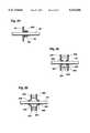
- FIG. 7is a side, cross-sectional view of a valve utilizing sphincter seals, made in accordance with the principles of the present invention.
- FIG. 8is a side, cross-sectional view of another embodiment of a valve, also utilizing sphincter seals, made in accordance with the principles of the present invention.
- FIG. 9is a side, cross-sectional view of a spool valve mechanism for use in volumetric pumps of the present invention for controlling the flow of fluid;
- FIGS. 10, 11, 12, 13 and 13Ashow five illustrative embodiments of drive mechanisms which may be utilized for driving the pump shaft of the volumetric pumps of the present invention
- FIG. 14shows a side, cross-sectional view of a fluid pressure detector for use with volumetric pumps of the present invention, among others;
- FIG. 15is a side, cross-sectional view of a further embodiment of a fluid pressure detector
- FIG. 16is a side, cross-sectional view of yet a further embodiment of a fluid pressure detector
- FIG. 17is a side, cross-sectional view of a ball valve for use with volumetric pumps of the present invention, among others;
- FIG. 18is a view along line 18--18 in FIG. 17;
- FIG. 19is a side, cross-sectional view of a plunger bottoming detector according to the invention.
- FIG. 20is a side, cross-sectional view of another embodiment of a valve according to the invention.
- FIG. 21is a side, cross-sectional view of another embodiment of a seal according to the invention.
- FIG. 22is a top, schematic view of a programming card system for controlling the driving mechanism in the present invention.
- FIG. 23is a side, cross-sectional view of the programming card system of FIG. 22;
- FIG. 24is a fragmented, side, cross-sectional view of a spring assisted seal arrangement suitable for use in the present invention.
- FIG. 25is a fragmented, side, cross-sectional view of a duplex, inwardly turned sphincter seal arrangement suitable for use in the present invention.
- FIG. 26is a fragmented, side, cross-sectional view of a duplex, outwardly turned sphincter seal arrangement suitable for use in the present invention.
- FIG. 1there is shown a perspective view of a volumetric pump made in accordance with the present invention to include a generally elongate housing 4, formed with an elongate cavity 8 therein (refer to FIG. 3 which also shows the housing 4 and the elongate cavity 8).
- the housing 4might illustratively be formed with an exterior shell 12 made of metal or hard plastic, and an interior filler 16 disposed against the shell 12, with the cavity 8 formed centrally therein.
- the fillercould similarly be metal or hard plastic.
- a resilient sheet of material 20Disposed in one end of the housing 4 is a resilient sheet of material 20 made, for example, of latex rubber, silicone rubber, or nitrile rubber.
- the sheet of material 20fills the end of the housing 4 to prevent communication between the outside of the housing and the cavity 8 except through an aperture 24 positioned in line with the cavity 8.
- An inlet duct 28is formed in the housing 4 generally adjacent to the sheet of material 20, to communicate with the cavity 8, and an outlet duct 32 is similarly formed in the housing to communicate with the cavity at the other end thereof (FIG. 3).
- Conduits 36 and 40respectively couple ducts 28 and 32 to a fluid source 44 and a fluid sink 48 (FIG. 1).
- Check valves 52 and 56are disposed respectively in conduits 36 and 40 to allow fluid to flow from the fluid source 44 into the cavity 8 and prevent the reverse flow, and to allow fluids to flow from the cavity 8 to the fluid sink 48 and prevent the reverse flow.
- the fluid source 44could be any source of fluid which it is desired to be pumped to fluid sink 48, such as an IV administration set which includes a bottle of fluid to be administered to a patient, with the fluid source 44 being the bottle and the fluid sink 48 being the patient receiving the fluid.
- an IV administration setwhich includes a bottle of fluid to be administered to a patient, with the fluid source 44 being the bottle and the fluid sink 48 being the patient receiving the fluid.
- the fluidic pump of FIG. 1could be used in a variety of environments.
- An elongate shaft or plunger 60is disposed in the aperture 24 of the sheet of material 20 to extend at least partially into the cavity 8 (FIG. 3) of the housing 4.
- the shaft 60may have a circular cross section and have a somewhat smaller circumference than that of the cavity 8 so that the shaft may be moved in a reciprocating fashion back and forth in the aperture 24 and cavity 8.
- the aperture 24is preferably shaped similarly to the cross-sectional shape of the shaft 60 and is preferably the same or slightly smaller in size in order to completely surround and grip the shaft to form a sphincter seal and prevent fluid from escaping the cavity 8.
- the apertureconforms to the shape of the shaft 60 even if their shapes are not identical, though it will be obvious to those skilled in the art that the more the shapes differ the less effective the seal will be.
- a coil spring 68is disposed about that portion of the shaft 60 which is outside of the housing to provide a bias force against the bumper pad 64 to urge the shaft outwardly from the housing.
- a support rod 72is mounted on the top of the housing 4 and extends forwardly therefrom, and a stopper finger 76 is slidably mounted on the rod 72 so that it may be slid forwardly or rearwardly along the rod.
- a set screw 80is provided in the stopper finger 76 to allow for setting or fixing the position of the stopper finger on the rod. Stopper finger 76 extends downwardly to a position in the pathway of possible movement of the bumper pad 64 to prevent the bumper pad and thus the shaft 60 from moving outwardly from the housing 4 beyond the location of the stopper finger.
- FIG. 1shows the bumper pad 64 resting against the lower end of the stopper finger 76 to illustrate that the bumper pad 64 and shaft 60 are prevented from moving any further outwardly from the housing 4.
- the setting of the stopper finger 76 by means of the set screw 80determines the stroke or excursion of movement of the shaft 60 within the cavity 8 of the housing 4.
- a driving mechanism 84such as a solenoid, is positioned in front of the housing 4 so that a solenoid drive core 88 extends toward the bumper pad 64 as shown.
- the drive mechanism 84is activated (for example by applying an electrical current to a solenoid)
- the driver core 88is caused to move towards the bumper pad 64, engage it and move the bumper pad and the shaft 60 toward the housing 4 so that the shaft moves further into the cavity 8 of the housing.
- the drive mechanism 84is deactivated, the drive core 88 retracts into the drive mechanism 84 allowing the coil spring 68 to urge the bumper pad 64 and thus the shaft 60 outwardly from the housing until the bumper pad contacts the stopper finger 76.
- Alternative activation and deactivation of the drive mechanism 84will thus result in the shaft 60 being reciprocated within the cavity 8 of the housing 4.
- One advantage to the pumps shown in FIGS. 1 and 3is that the shapes of the plunger and cavity cause gas bubbles to be swept out of the cavity with each stroke of the plunger, instead of accumulating in the cavity, especially around the seal made in the sheet 20. This allows for greater volumetric accuracy in the pumping action.
- FIG. 1Ashows a fragmented, side, cross-sectional view of the shaft 60, the aperture 24 in the resilient sheet 20, with the addition of forward and rear seal supports 90 and 92.
- the supports 90 and 92allow for greater positive or negative fluid pressure in the cavity 8 by supporting the sheet 20 at the aperture 24 so that it does not distend with the movement of the shaft 60 into the cavity (to thus stretch and degrade the resilient material and damage the seal), or collapse with the movement of the shaft 60 out of the cavity (to further degrade the material and damage the seal). Greater fluid pressure in the cavity exacerbates the problems of distending and collapsing the sheet 20, which the supports 90 and 92 help prevent.
- the rear support 92preferably comprises an inflexible flat plate with an aperture 92a formed therein.
- the aperture 92ais preferably similar in shape and slightly larger in size than the shaft 60 to allow free movement of the shaft therein, and is located close to the sheet 20. During movement of the shaft 60 into the cavity 8, the friction of the shaft 60 against the sheet 20 at the aperture 24 tends to cause the latter to distend toward the cavity 8. The sheet 20 at the aperture 24, however, contacts the support 92 before distending enough to damage the material or loosen the seal.
- the support 90preferably comprises a plate with an aperture 90a formed therein, but also a lip 90b around the aperture, extending toward the cavity 8.
- the lipis preferably shaped to approximate the shape of the sheet 20 at the aperture 24 after the shaft 60 has been inserted therein.
- the support 90prevents collapsing and maintains the desired position of the sheet 20 at the aperture 24 during withdrawal of the shaft 60 from the cavity 8.
- the support 90also bears a large amount of fluid pressure from the cavity 8, relieving somewhat the pressure on the sheet 20.
- FIG. 1Bshows another pump similar to that shown in FIG. 1 except that the cavity 8 is close to the shape and size of the plunger 60 in cross section except for a trough 94 which runs adjacent the length of the cavity. Also, the cavity 8 is enlarged in an area 8a around the sphincter seal to be in fluid communication with an inlet conduit 36, such that fluid can flow from the conduit 36 into the cavity 8 and trough 94 even when the plunger 60 is inserted into the cavity.
- the pumping action in the embodiment of FIG. 1Bis the same as in FIGS. 1, and the cavity 8 shape and size with trough 94 helps to further eliminate bubbles from low-flow areas in the cavity.
- FIG. 2shows a fragmented, side, cross-sectional view of one embodiment of a drive/pump shaft interface for terminating the pumping action if too little or too much pressure is created in the pump cavity 8.
- the shaft 60is slidably disposed in the cavity 8 and extends outwardly through an aperture 24 in the resilient sheet of material 20 to terminate at a free end 60a.
- the magnet cap 100is magnetically attracted to the free end 60a of the shaft 60 to remain in place until a force greater than the magnetic attraction force pulls the magnet cap from off the free end 60a of the shaft 60.
- bracket 104Formed on the end of a driver core 88 is a bracket 104, made of a ferro-magnetic material, which branches into two fingers outwardly and then behind the magnet cap 100, to positions in contact with a rear surface of the magnet cap. The two fingers of the bracket 104 are magnetically attracted into contact with the magnet cap 100 and will remain in contact until a force greater than the magnetic force of attraction is applied to the bracket in a direction toward the housing 4.
- the pumping action of movement of the shaft 60 in the cavity 8will be stopped if a resistance force to movement of the shaft is encountered either in pushing the shaft further into the cavity 8 or pulling the shaft outwardly of the cavity.
- the resistance force to pulling the shaft 60 outwardly of the cavity 8exceeds the force of attraction of the magnet cap 100 to the free end 60a of the shaft, the magnet cap will be pulled from off the free end by the bracket 104, and the pumping action will stop.
- the resistance force to pushing the shaft 60 further into the cavity 8exceeds the force of magnetic attraction of the bracket 104 to the magnet cap 100, then the bracket will be pushed free from contact with the magnet cap and, again, the pumping action will stop.
- the advantage of this arrangementis that unexpected resistance to pumping, such as a clogged inlet or a clogged outlet, or other clogging in the fluid pathway, will result in the pumping action being stopped.
- the stopping of the pumping actioncould also be used to alert the pump user of a problem in the fluid pathway.
- FIG. 3is a side, cross-sectional, schematic view of another embodiment of a volumetric pump in which the same housing structure 4 as that of FIG. 1 is employed.
- valves 110 and 114disposed respectively in conduits 36 and 40, are not check valves as in FIG. 1, but rather are controlled by a control unit 118.
- the valves 110 and 114still control the flow of fluid from a fluid source 44 to the cavity 8 and from the cavity 8 to a fluid sink 48, but this is all done under control of the control unit 118.
- the control unit 118also controls operation of an electric motor 122 whose drive shaft 126 is coupled to a drive wheel 130.
- the motor 22operates to rotate the drive shaft 126, the wheel 130 is rotated.
- a drive nipple 134is mounted near the perimeter of the drive wheel 130 and is pivotally coupled to one end of a drive shaft 138 which, in turn, is pivotally coupled at its other end to the free end of the pump shaft 60.
- the drive shaft 138is caused to reciprocate back and forth and, in turn, cause the shaft 60 to reciprocate in the cavity 8.
- a second housing 140is provided in the preferred embodiment around the housing 4, pump shaft 60, drive shaft 138, drive wheel 130, and a portion of the drive shaft 126, to seal the components from outside contamination or interference.
- the housing 140preferably comprises rigid material such as steel or plastic except around the drive shaft 126, where it comprises a sheet of resilient material 142, similar to the sheet 20, with an aperture 144 formed therein to create a sphincter seal on the drive shaft 126 similar to the seal of the sheet 20 around the pump shaft 60.
- the sheet 142 at the aperture 144seals the drive shaft 126 during rotational, rather than reciprocal, movement.
- control unit 118causes the motor 122 to operate and rotate, with the angular position of the drive shaft 126 being fed back to the control unit. Based on the angular position of the drive shaft 126 and thus the drive wheel 130, the control unit will cause valves 110 and 114 to alternately open and close to allow fluid to flow from the fluid source 44 into the cavity 8 on the withdrawal stroke or movement of the shaft 60, and allow fluid to flow from the cavity 8 to the fluid sink 48 on the pump stroke of the shaft 60.
- control unit 118might illustratively be any conventional microprocessor used for controlling operation of electrical equipment.
- FIG. 4shows a side, cross-sectional view of a volumetric pump according to the invention, incorporated into a hypodermic needle 150.
- the embodiment of FIG. 4may be used, for example, to pump medication directly into a patient's bloodstream without the need for intervening tubes and the like.
- the needle 150has an elongate interior cavity 152 and an open outlet end 154.
- a resilient sheet of material 20is disposed over the opposite end of the needle, and a shaft or plunger 60 is disposed through an aperture in the sheet 20 for movement inwardly and outwardly of the cavity 152, in the same manner as previously described with regard to FIGS. 1 through 3.
- An inlet conduit 156extends through the side of the needle 150 into the cavity 152 for supply of a fluid into the cavity from a fluid source 44.
- a valve 52which may be a mechanical check valve or electronically controlled valve as have been previously described, is located in the inlet conduit 156 and allows fluid to flow from the fluid source through the inlet conduit to the cavity 152, while preventing flow in the opposite direction.
- a similar valve 158is provided in the cavity 152 forwardly of the shaft 60 to allow forward movement of fluid from the shaft to the outlet end 154 of the needle, while preventing flow in the opposite direction.
- the shaft 60In operation, when the shaft 60 is moved rearwardly (outwardly) from the cavity 152 under power of a drive means (not shown but described in this specification or other suitable drive means), it creates a negative pressure in the cavity 152, causing fluid from the fluid source 44 to enter the inlet conduit 156 and pass through the valve 52 into the cavity 152.
- a drive meansnot shown but described in this specification or other suitable drive means
- the shaft 60reverses direction and moves forwardly (inwardly) into the cavity 152, it creates a positive pressure that pushes the fluid in the cavity through the valve 158 out the outlet end 154 of the needle and into, for example, the patient in which the needle is inserted.
- medication or other fluidcan be steadily pumped directly into a patient.
- FIG. 5is a fragmented, side, cross-sectional view of another embodiment of a volumetric pump in accordance with the invention.
- the elongate housing 172 of the pumpcontains two interior cavities: an inlet cavity 174 at the rear of the housing and an outlet cavity 176 at the front of the housing.
- a passage 178provides communication between the two cavities.
- a sheet of resilient material 20is disposed in the inlet cavity 174, closing off a portion of the cavity such that the only openings to it are an aperture 24 in the sheet 20 and the passage 178.
- An elongate pump shaft or plunger 180is disposed in the inlet cavity 174 through the aperture 24 forming a sphincter seal as previously described.
- a drive bracket 182, driven by suitable drive means (not shown),is connected to the pump shaft 180 and moves the latter back and forth in reciprocal movement inwardly and outwardly of the inlet cavity 174. As in previously-described embodiments, the drive bracket 182 does not move the pump shaft 180 so far as to pull it out of the sphincter seal.
- a forward portion 180a of the pump shaft 180which extends through the sphincter seal formed by the resilient sheet 20 and aperture 24 and which is connected to the drive bracket 182, is rigid in the preferred embodiment.
- a rear portion 180b of the pump shaftis flexible. One end of the rear portion 180b attaches to the forward portion 180a, while the other end attaches to a fluid source (not shown).
- the rear portion 180b of the pump shaftis flexible to accommodate the reciprocating movement of the forward portion of the shaft while enabling it to remain connected to a stationary fluid source.
- An inlet conduit 184is formed in the pump shaft 180 for supplying fluid from the fluid source into the inlet cavity 174.
- a plug 186is disposed at the end of the inlet conduit 184 in the inlet cavity.
- the plugis connected by a coil spring 188 to a pin 190 fixed in the interior of the inlet conduit 184, the arrangement being configured such that the spring urges the plug against the opening of the inlet conduit 184 absent other forces.
- a second plug 192is urged against the passage 178 under force of a coil spring 194 attached at one end to the plug 192 and at the other to a pin 196 fixed in the outlet cavity. Absent other forces, the plug 192 closes communication via the passage between the inlet cavity 174 and the outlet cavity 176.
- the pump shaft 180When the pump shaft 180 reverses direction and moves forwardly (inwardly) into the cavity 174, it creates a positive pressure in the cavity 174 which pushes the plug 186 back on its seat with the assistance of the spring 188.
- the positive pressurealso overcomes the force of the spring 194 holding the plug 192 against the passage 178, forcing the plug back and allowing fluid to flow from the inlet cavity 174 into the outlet cavity 176, and from there to, for example, a fluid sink or patient.
- FIG. 6is a fragmented, side, cross-sectional view of a further embodiment of a volumetric pump according to the invention.
- a fluid inlet passage 200formed of suitable tubing or piping leads from a fluid source (not shown) into dual inlet conduits 202 and 204, each having a check valve 206 for prevention of backward flow.
- the inlet conduitsare connected to opposite ends of an elongate housing 208 which contains interior cavities 210 and 212 which, in turn, are separated by a sheet 20 of resilient material disposed in the housing.
- the inlet conduit 202leads into the cavity 210, while the inlet conduit 204 leads into the cavity 212.
- An elongate pump shaft 60is disposed within the two cavities and through an aperture 24 in the sheet 20, forming a sphincter seal as previously described.
- a drive shaft 214attaches to one end of the pump shaft 60 to drive the pump shaft back and forth within the cavities 210 and 212 and through the sheet 20.
- the drive shaft 214is powered by any suitable drive means apparent to those skilled in the art in light of this disclosure.
- a resilient sheet of material 20ahaving an aperture 24a is disposed at one end of the housing 208, through which the drive shaft 214 passes, forms a sphincter seal as previously described.
- Outlet conduits 216 and 218lead out of the cavities 210 and 212, respectively, into a combined fluid outlet passage 220.
- each outlet conduit 216 and 218has a check valve 206 for prevention of backward flow of fluid.
- valves 206prevent fluid from flowing in the conduits in any direction but from the fluid inlet 200 toward the fluid outlet 220.
- FIG. 6Ais a side, cross-sectional view of an embodiment of a volumetric pump similar to that illustrated in FIG. 6, but with a different drive system which eliminates the need for a drive shaft entering the housing.
- drive coils 230 and 232are disposed around the cavities 210 and 212, respectively, each coil comprising in the preferred embodiment a series of conductive wires wrapped around the housing 208 defining the cavities.
- Wires 234connect the coils to sources of electrical current (not shown).
- a pump shaft 236, disposed in the cavities 210 and 212 and through an aperture 24 in sheet of material 20,is preferably constructed of ferro-magnetic or permanent magnet material.
- the coil 230When the coil 230 is supplied electrical current through the wires 234, it creates a magnetic field which draws the pump shaft 236 into the cavity 210, as will be apparent to those skilled in the art, until it reaches a fixed permanent magnet 238.
- the fixed magnet 238serves to keep the shaft in position without assistance from the coil 230. Electrical current to the coil 230, therefore, is supplied only momentarily to initially draw the shaft into the cavity 210.
- the coil 232when the coil 232 is momentarily energized, it creates a magnetic field which, in the preferred embodiment, overcomes the force of the magnet 238 against the shaft 236 and draws the shaft into the cavity 212 until it reaches a fixed permanent magnet 240, which keeps the shaft in position.
- FIG. 6Afurther shows diaphragms 242 and 244 made of resilient material located at the ends of the housing 208.
- the diaphragmshave some give in them and each bows outwardly when the shaft moves toward it with sufficient force, creating positive pressure in the cavity; for example, diaphragm 242 bows outwardly when the shaft moves into cavity 210.
- each diaphragmmoves inwardly when the shaft moves away from its corresponding cavity, creating a negative pressure.
- the diaphragmslessen the pressure in the cavities caused by movement of the shaft, allowing the shaft to move quickly from one side to the other without power loss in the drive coils 230 and 232 in cases where the inlet and/or outlet conduits are long or otherwise restrictive to fluid flow.
- the diaphragmscan be made more or less compliant depending on the degree to which the pressure caused by shaft movement is desired to be modified.
- the diaphragmsmay also be added to other embodiments of the volumetric pump described herein.
- FIG. 6Bis a fragmented, side, cross-sectional view of a further embodiment of a pump similar to that illustrated in FIG. 6, but again with a different drive system.
- the housing 208contains three cavities: the cavities 210 and 212 in their usual positions at the juncture of the inlet and outlet conduits, and an additional interior cavity 252 between the cavities 210 and 212, each cavity separated from the other by a resilient sheet 20 with an aperture through which the pump shaft 60 passes, forming sphincter seals in the manner previously described.
- the interior cavity 252is not used to pump fluid. Rather, it houses a slider 254, preferably cylindrical with a bore through its center and through which the shaft 60 passes.
- the slider 254is made of ferro-magnetic or permanent magnet material, disposed coaxially around the pump shaft 60, and has recesses 258 and 260 on either end adjacent the pump shaft.
- Drive coils 230 and 232 and magnets 238 and 240are provided to move the slider 254 back and forth in the same manner of moving the shaft 236 back and forth in FIG. 6A.
- the shaft 60 in FIG. 6Bpreferably is non-magnetic in order not to be affected by the coils and magnets.
- the slider 254is positioned on and connected to the pump shaft 60 by means of flanges 262 and 264 extending outwardly from the shaft near opposite ends, and coil springs 266 and 268 disposed respectively in the recesses 258 and 260 around the shaft and between the flanges and the slider.
- the spring 266urges the slider 254 away from the flange 262
- the spring 268urges the slider away from the flange 264.
- the coil 230In operation, when the coil 230 is energized (by an electrical current source not shown) it draws slider 254 in the direction of the cavity 210 until it abuts the magnet 238, which holds it in position.
- the sliderapplies directional force to the pump shaft 60 through the spring 266, causing the shaft to move into the cavity 210.
- the springis compliant and will lessen the momentary force of the shaft relative to the slider, slightly lessening the momentary positive pressure in the cavity 210 and negative pressure in the cavity 212.
- the springs 266 and 268thus perform the same function as the diaphragms 242 and 244 in FIG. 6A.
- FIG. 6Cis a fragmented, side, cross-sectional view of a further embodiment of a pump similar in all respects to the embodiment of FIG. 6A except that a pump shaft 236 is driven by a single elongate annular magnet 280 instead of by coils 230 and 232 and magnets 238 and 240.
- the magnet 280is slidably disposed around the housing 208 and is moved back and forth by any suitable mechanical means such as the drive mechanisms of FIGS. 1 and 3. As the magnet moves toward the cavity 210, it draws the shaft 236 toward the cavity 210 by magnetic attraction, and as it moves toward the cavity 212, it draws the shaft 236 toward the cavity 212 by magnetic attraction.
- FIG. 7shows a side, cross-sectional view of a valve using sphincter seals in accordance with the invention.
- an elongate housing 292is formed of suitable rigid material with a closed end 294. The other end is closed by a resilient sheet of material 20 with an aperture 24 through which a shaft 60 passes, forming a sphincter seal in the manner previously described.
- a second sheet of resilient material 20a with an aperture 24ais disposed within the housing 292, dividing it into two cavities 296 and 298, with the aperture 24a serving as a passage therebetween.
- the shaft 60passes only selectively, rather than continuously, through the aperture 24a.
- a fluid inlet 300is formed in the housing 292 leading into the cavity 296, and a fluid outlet 302 is formed in the housing leading from the cavity 298.
- a fluid source 304is connected to the fluid inlet 300, and a fluid sink 306 is connected to the fluid outlet 302.
- One or both of the source 304 and sink 306is pressurized to urge fluid from the source to the sink through the valve.
- the apertureserves as a passage between the cavities 296 and 298, allowing fluid to flow from the fluid source 304, through the inlet 300, into the cavity 296, through the aperture 24a, into the cavity 298, through the outlet 302, and into the fluid sink 306.
- a sphincter sealis formed and communication between the cavities 296 and 298 is blocked, stopping fluid flow. In this manner, the structure of FIG. 7 operates as a valve.
- FIG. 8shows a side, cross-sectional view of another embodiment of a valve using sphincter seals according to the invention, which can be used to switch fluid flow from one destination to another, or stop flow altogether.
- a housing 310is divided into three interior cavities 312, 314, and 316 by two sheets of resilient material 20 and 20a, each having an aperture 24 and 24a, respectively.
- An elongate shaft 60moves back and forth through the cavities and apertures, driven by a drive shaft 318 which passes through an aperture 24b in a sheet of resilient material 20b disposed in an opening 311 in the side of the housing 310, forming a sphincter seal as previously described.
- An inlet conduit 320 leading from a fluid sourceleads into the middle cavity 314.
- Outlet conduits 322 and 324lead out of cavities 312 and 316, respectively, to fluid sinks (not shown). Either the fluid source or fluid sinks, or both, are pressurized to urge fluid from the source to the sinks.
- the shaft 60selectively passes through the apertures 24 and 24a, selectively forming sphincter seals and blocking fluid flow between the cavities.
- the shaft 60may be made long enough to enable it to pass through both apertures 24 and 24a at the same time, completely blocking fluid flow, or may be made shorter so that it is unable to pass through both apertures at the same time.
- the shaft 60moves toward the cavity 312, it passes through the aperture 24, forming a sphincter seal therein and blocking fluid flow between the cavities 312 and 314.
- the shaft 60comes out of the aperture 24a, opening the aperture and enabling fluid to flow from the inlet cavity 314 into the cavity 316 and through the outlet conduit 324 to the fluid sink.
- the shaft 60moves toward the cavity 316, it passes through the aperture 24a, forming a sphincter seal therein and blocking fluid flow between the cavities 314 and 316.
- the shaftcomes out of the aperture 24, opening the aperture and enabling fluid to flow from the inlet cavity 314 into the cavity 312 and through the inlet conduit 322 to the fluid sink. If the shaft has been made long enough, it may be centered in the cavity 314, passing through both apertures 24 and 24a and blocking all fluid flow.
- FIG. 9shows a side, cross-sectional view of a spool valve mechanism for controlling the flow of fluid, combined with a pump similar to that of FIG. 3.
- This embodiment of the inventioncomprises a housing 320 containing an interior cavity 322.
- An elongate valve shaft 324is disposed inside the cavity 322, and an elongate drive shaft 326, of smaller diameter than the valve shaft 324 in the preferred embodiment, is connected to one end of the valve shaft.
- the drive shaft 326passes through a passage 328 formed in the housing to extend from the cavity 322 to the exterior.
- a resilient sheet of material 20 having an aperture 24is disposed on the housing on the exterior side of the passage 328, and the drive shaft 326 passes through the aperture to form a sphincter seal as previously described.
- the drive shaft 326can be used to move the valve shaft 324 back and forth in a reciprocating motion, or merely to stabilize the valve shaft in position, or simply not be used or removed from the apparatus.
- the valve shaft 324includes two flanges 330 and 332 spaced apart from one another.
- the flangesmay extend only partially around the circumference of the valve shaft 324, as shown, or completely around, if desired, though in the latter case, the bottom of the cavity 322 would need to be lowered from what is shown in the drawing.
- a piston 334is disposed in the cavity above the valve shaft 324 and substantially parallel thereto.
- a tab 336extends downwardly from the piston sufficiently far to abut either of the flanges 330 or 332 when the piston is moved longitudinally a sufficient distance.
- the piston 334extends from the cavity to the exterior of the housing 320 through a passage 338 formed in the housing.
- a resilient sheet of material 20a, with an aperture 24a,is disposed across the passage 338, and the piston passes through the aperture to form a sphincter seal as previously described.
- An inlet conduit 340passes through the housing into the cavity 322, near the connection of the valve shaft 324 to the drive shaft 326.
- a resilient sheet of material 20b, with an aperture 24b,is disposed across the inlet conduit substantially parallel to the sheet 20, with the apertures 20 and 20b aligned along the drive shaft 326.
- the aperture 24bis larger than the aperture 24, enabling the drive shaft 326 to pass through the aperture 24b without forming a sphincter seal, though the aperture 24b is small enough to form a sphincter seal with the valve shaft 324 when the latter passes therethrough.
- An outlet conduit 342passes through the housing into the cavity 322 near the opposite end of the valve shaft 324 from the inlet conduit 340.
- the valve shaft 324selectively passes through the aperture 24c, forming a sphincter seal therewith when passing through it.
- the inlet and outlet conduitsare attached to a fluid source and a fluid sink, respectively (not shown).
- the valve shaft 324may be made long enough so that when it is centered between the sheets 20b and 20c it passes through both corresponding apertures 24b and 24c and forms sphincter seals with both. Alternatively, the shaft may be made short enough so that when centered between the two sheets it passes through neither aperture.
- the valve shaftmay be moved back and forth by either the drive shaft 326 attached to suitable drive means, or the piston 334 attached to suitable drive means. If moved by the piston 334, the shaft 324 is moved in the following way: to cut off fluid flow to the outlet conduit 342, the piston is moved toward the outlet conduit until the tab 336 abuts the flange 332 on the valve shaft 324 and pushes the shaft into the aperture 24c.
- the pistonis moved toward the inlet conduit 340 until the tab 336 abuts the flange 330 on the valve shaft 324 and pushes the shaft into the aperture 24b.
- the location of the drive shaft 326 through the aperture 24bdoes not prevent fluid flow from the inlet conduit into the cavity since, as previously noted, the aperture is of a larger diameter than the drive shaft.
- the positive and negative pressures required to cause fluid flow from the fluid source into the cavity 322, and from the cavity 327 to the fluid sinkare produced by the motion of the piston 334, i.e., a pumping action.
- FIGS. 10, 11, 12, 13 and 13Ashow five illustrative embodiments of drive mechanisms which may be used to drive the pump or valve shafts of the present invention.
- FIG. 10shows a side view of a drive mechanism which includes an elongate drive shaft 350 attached to a pump or valve shaft 60, with a notch 352 cut on the bottom of the drive shaft 350.
- a ramp 354 containing a shoulder 356is disposed beneath the drive shaft 350. The shoulder 356 divides the ramp into a lower portion 354a and a higher portion 354b. Rollers 358 or other suitable adjustment means are disposed on the underside of the ramp to allow adjusting its longitudinal position to thus vary the stroke length of the pump shaft 60, as described below.
- a secondary driver 360is disposed on rollers 362 which rest on the lower portion 354a of the ramp.
- a tab 364extends upwardly from the forward end of the secondary driver nearest the shoulder 356.
- a disc 366 given rotary motion by a motor or other drive meansconnects to the end of the secondary driver opposite the tab 364 by a rod 368, which is pivotally attached at one end to the disc and at the other to the secondary driver.
- the rotary motion of the disc 366moves the secondary driver 360 back and forth in a conventional manner.
- the notch 352must initially be placed in position to receive the tab 364 when the latter is elevated by the shoulder 356.
- the stroke of the drive shaft 350may be easily adjusted by moving the ramp 354 forwardly or rearwardly. If the ramp is moved rearwardly (with appropriate adjustment of the drive shaft 350 to align the notch), the tab 364 enters the notch earlier in the forward movement of the secondary driver 360, moving the drive shaft farther forward, and correspondingly farther rearward. If the ramp is moved forwardly, the tab enters the notch later in the forward movement of the secondary driver 360, moving the drive shaft a lesser distance forward and a correspondingly lesser distance rearward.
- Varying the stroke of the drive shaft 350adjusts the flow rate of the pump while allowing the driver to be run at a constant rate.
- Other control or drive mechanismsmay be used to accomplish the same end (i.e., adjust the flow rate) such as variable speed drive mechanisms, and variable delay of constant speed drive mechanisms.
- FIG. 11shows another drive mechanism comprising a pump or valve shaft 60 driven by a drive shaft 372 having teeth 374 on one side.
- a wheel 376 having teeth 378 spaced circumferentially therearoundengages the teeth 374, converting rotary movement of the wheel into longitudinal movement of the drive shaft. The rotary movement of the wheel reverses direction to reverse direction of the drive shaft.
- FIG. 12shows another drive mechanism comprising an elongate drive shaft 380 connected to a pump or valve shaft 60.
- the drive shaft 380has a threaded interior recess 382 into which a threaded rod 384 fits.
- the rodis caused to rotate by a motor 386.
- the rotational motion of the rod 384moves the drive shaft 380 back or forth.
- FIG. 13shows a perspective view of another drive mechanism for a pump shaft 60 attached at one end to a rigid anvil 390 which is oval-shaped in side cross section.
- a flexible filament 392 made of suitably strong materialis wrapped snugly around the anvil, with a loop of the filament wrapped around a drive shaft 394 which is given rotational motion by a motor 396.
- the drive shaftrotates to thus move the filament 392
- the anvil and thus the pump shaftare caused to move longitudinally, as the drive shaft 394 gathers in and lets out filament 392 to accommodate its rotational movement, the manipulated filament forces the anvil to move in turn.
- FIG. 13Ashows a plunger 60 driven by a drive shaft 430 which is pivotally connected at an outer end 60a to an end 432 of the drive shaft.
- a crank 434is pivotally connected to the other end 435 of the drive shaft 430.
- the crankis rotated by any suitable means, moving the drive shaft 430 in a reciprocating fashion and thus the plunger 60 back and forth in longitudinal movement.
- sphincter seals as described aboveare formed at fluid interfaces with the components.
- FIGS. 14 through 16show fluid pressure detectors for use, for example, with the volumetric pumps of the present invention to detect when pressure exceeds a certain level or falls below a certain pressure.
- a housing 400is formed with an interior cavity 402 which is bisected by a conventional compliant diaphragm 404.
- a flexible conductive disc 405is disposed on top of the diaphragm 404.
- Two conductivity sensors 466are disposed at the top of the cavity 402.
- An inlet conduit 408leads into the cavity 402 from a fluid port 410.
- the fluid entering the cavitycauses the diaphragm 404 to bow upwardly, until at a predetermined pressure it bows sufficiently far to cause the conductive disc 405 to contact the conductivity sensors 406, electrically shorting them to indicate overpressure in the port.
- a fluid port 412includes an opening 414 through its wall and a diaphragm 404 covering the opening.
- a T-shaped lever 416pivotally attached at one end to a stationary point 419, with arms 416a and 416b disposed between and contacting at their ends the diaphragm 404 and a flexible conductive dome contact 418.
- the dome contactis disposed on a support 420.
- a conductivity sensor 406is positioned on the support in alignment with the dome contact.
- the fluid entering the opening 414causes the diaphragm 404 to bow upwardly, causing, through the arms 416a and 416b of the lever 416, the dome contact 419 to flatten against the support 420.
- the diaphragmbows sufficiently far to cause the dome contact 419 to flatten and contact the conductivity sensor 406, indicating overpressure in the port 412.
- FIG. 16shows a fragmented, side, cross-sectional view of a detector for detecting underpressure of fluid in a port 412 (instead of overpressure as in FIGS. 14 and 15).
- an opening 414is formed with shoulders 422 to limit upward bowing of a diaphragm 404 disposed in the opening.
- a coil spring 424together with normal fluid pressure in the port 412, urges the diaphragm 404 against arm 416 which flattens a dome contact 419 to contact a conductivity sensor 406.
- the diaphragm 404begins to flatten toward the port, causing the dome contact 419 to break its connection with the conductivity sensor 406, indicating underpressure in the port.
- FIGS. 17 and 18show respectively a side, cross-sectional view, and a view taken along lines 18--18 of FIG. 17, a ball valve for use with volumetric pumps of the present invention, among other mechanisms.
- the ball valvecomprises a housing 440 defining therein two adjacent cavities 442 and 444 (FIG. 18) having a passage 446 therebetween.
- An inlet conduit 448leads into the cavity 442 from the exterior of the housing, and an outlet conduit 450 leads from the cavity 444 to the exterior of the housing on the opposite side of the housing from the inlet conduit.
- Walls 454separate the cavities from the exterior and each other.
- a resilient sheet of material 456(FIG. 17) made of, for example, latex or silicone rubber, is disposed over the cavities and is pressed against the walls 454 by a top portion 440a of the housing 440, sealing the cavities against fluid communication with the exterior or with each other except through the passage 446.
- An aperture 458is formed through the top portion 440a of the housing to extend down to the sheet 456 in alignment with the passage 446, and a ball 460 is disposed in the aperture.
- fluid from the inlet conduit 448flows into the cavity 442.
- the valveWhen the valve is in open position (shown in FIG. 17), the fluid continues through the passage 446 into the cavity 444 and out the outlet conduit 450.
- the ball 460To close the valve, the ball 460 is pushed down, forcing the sheet 456 to bend downwardly into the passage 446, sealing it from fluid flow. This action stops fluid flow between the cavities.
- FIG. 19shows a fragmented, side, cross-sectional view of a plunger "bottoming" detector using the principles of the present invention.
- a generally elongate housing 470includes therein an elongate cavity 472 which is divided into adjacent compartments 472a and 472b by a resilient sheet of material 20 containing an aperture which forms a sphincter seal with a shaft or plunger 60 as previously described.
- a passage 474connects the compartment 472b with a fluid chamber 476 having an aperture 478 through which is disposed a rod 480 having a piston 482 disposed on one end in the fluid chamber 476.
- the other end 480a of the rod 480is preferably operatively connected to a valve or switch (not shown).
- the bottoming detector of FIG. 19is designed to detect when the plunger 60 reaches the end of a stroke, or, alternatively, if it has gone beyond the anticipated reciprocating distance, to take appropriate action.
- the plunger 60moves in reciprocating motion.
- its end 60areaches the sheet 20, it forms a sphincter seal with the sheet.
- fluidis forced from the compartment through the passage 474 and into the fluid chamber 476, increasing pressure in the latter and urging the piston 482 toward the aperture 478, moving the rod 480 and activating the valve or switch to which it is connected.
- movement of the plunger 60 beyond the sheet 20may be detected to alert a user.
- FIG. 20shows another embodiment of a valve according to the invention, comprising a generally elongate housing 490 defining an elongate internal cavity 491 with three sheets of resilient material 20a, 20b, and 20c disposed therein, each sheet containing an aperture for formation of sphincter seals, as previously described.
- the sheets 20a, 20b, and 20care spaced from each other, forming four fluid compartments 490a, 490b, 490c, and 490d in the cavity 490.
- a plunger 60is disposed in the cavity through the aligned apertures in the sheets, forming sphincter seals therewith.
- the shaftcontains an internal passage 492 running partially along its length with spaced openings 494 and 496 at each end of the passage, in fluid communication with the cavity.
- An inlet 498is formed through the housing wall into the compartment 490b, and an outlet 500 is formed through the housing wall into the adjacent compartment 490c.
- the openings 494 and 496are spaced such that when the opening 494 is located in the compartment 490b, the opening 496 is located in the compartment 490c, providing fluid communication from the inlet 498, through the compartment 490b, opening 494, passage 492, opening 496, and compartment 490c to the outlet 500.
- the openingsare moved from their respective positions in the compartments 490b and 490c, blocking communication between the inlet and outlet. This, of course, defines typical valve operation.
- the apparatus of FIG. 20can also be used to direct fluid received, for example, at the left side of the apparatus (indicated by arrow 493) either to inlet 498 (which would become an outlet) or to outlet 500.
- the passage 492would be long enough to allow positioning opening 496 in compartment 490c while opening 494 is still positioned in compartment 490a. Then, with opening 496 positioned in compartment 490c, fluid would flow through opening 494 and passage 492, out the opening 496 into compartment 490c, and then out the outlet 500.
- FIG. 21shows another embodiment of a seal suitable for use in certain applications of pumps or valves of the present invention. In some applications, this seal may be used instead of a sphincter seal as previously described.
- a generally elongate housing 510defines an interior cavity 512 which may be configured for the particular pump or valve application, such as with inlet and outlet passages 514 and 516.
- a shaft or plunger 60is disposed in the cavity and lengthwise aligned therewith.
- a portion 510a of the housingis configured to have a very close fit with the shaft 60, with just enough space between them to allow the shaft to slide in reciprocating movement back and forth in the cavity.
- the housing portion 510ais thicker than the resilient sheets used for sphincter seals in previous embodiments, and is preferably made of more rigid material such as glass, sapphire or metal. The seal formed between the housing portion 510a and the shaft, therefore, is not complete and leaks slowly. However, if the pump action is fast enough the leakage is comparatively insignificant and the seal is satisfactory.
- the seal of FIG. 21can be used in place of any sphincter seal previously described in connection with apparatuses of the present invention if the volume of fluid flowing through the apparatus is large compared to the leakage through the seal or the leakage is otherwise deemed unimportant to the operation of the apparatus.
- FIGS. 22 and 23show a top view and side, cross-sectional view respectively of a programming card system for controlling the drive systems of the present invention.
- the embodiment shown in FIGS. 22 and 23show only one of many ways of controlling the driving of the shafts or other moveable parts in embodiments of the present invention, such as the amplitude and frequency of the shaft's reciprocating movement.
- Other means of communicating the "program" to a system controllerinclude switches, including rotary switches, bar code readers, and electronic communication from a programming unit to the driver unit, etc.
- the programming card system of FIGS. 22 and 23is especially convenient for programming an IV pump controller, such as the control unit 118 of FIG. 3. A physician or pharmacist could readily prepare a card (as will be discussed momentarily) to control the parameters and operational mode of an IV pump as required for a particular patient.
- the programming card system of FIGS. 22 and 23comprises a programming card 520 containing selectively punched holes 522 (punched, for example, by a physician or pharmacist) and index tracks 524.
- the holes and tracksare arranged in columns and rows.
- the cardis designed for placement in a card reader 526, which comprises a series of conductive fingers 528 which are mounted on and biased against a printed circuit board 529 or equivalent structure which contains traces 530 electrically connected to a control unit or circuit 532.
- the tracesare disposed beneath the portion of the fingers which contacts the board 529, and detect when the fingers contact the board.
- the holes and index tracks in the programming cardare aligned with the fingers 528.
- the holeswhich are selectively chosen on the card, allow contact between the fingers and the traces, while other portions of the card which have not been punched out do not allow the electrical connection to be made, thus allowing the reader to interpret the information on the card and appropriately program the controller for the driver of the apparatus of the present invention.
- FIG. 24shows a fragmented, side, cross-sectional view of a sphincter seal, including a shaft 60 disposed in an aperture 24 formed in a sheet of flexible material 20.
- a lip 602 of the aperture 24 of the sheet of material 20is formed to turn inwardly toward the interior of the pump housing (not shown) to effectively lie snugly about a portion of the shaft 60.
- a coil spring 606is disposed about the lip 602 to urge the lip tightly against the shaft 60 to further enhance the seal between the sheet of material 20 and the shaft 60.
- FIG. 25shows a fragmented, side, cross-sectional view of a duplex sphincter shield arrangement, including a shaft 60, a first flexible sheet of material 620 having an aperture 624 formed therein, and a second sheet of flexible material 628 having an aperture 632 formed therein.
- a lip 636 of the aperture 624 of the sheet of material 620is turned inwardly as shown, as is a lip 640 of the aperture 632 of the sheet of material 628, so that the lips are facing inwardly towards one another.
- a ring 644is disposed between the sheets of material 620 and 628 to define a substantially airtight cavity 648 between the sheets of material 620 and 628, the ring 644, and the shaft 60.
- FIG. 26is a fragmented, side, cross-sectional view of a duplex sphincter seal arrangement again including a shaft 60, a pair of flexible sheets of material 650 and 654, each with apertures 658 and 662 respectively, for receiving the shaft 60.
- lips 664 of the sheet of material 650, and 668 of the sheet of material 654turning inwardly towards one another as in FIG. 25, the lips are turned outwardly away from one another as shown.
- a ring 672is disposed between the sheets of material 650 and 654 to define a cavity 676 similar to the cavity 648 of FIG. 25.
Landscapes
- Engineering & Computer Science (AREA)
- General Engineering & Computer Science (AREA)
- Mechanical Engineering (AREA)
- Health & Medical Sciences (AREA)
- Animal Behavior & Ethology (AREA)
- General Health & Medical Sciences (AREA)
- Biomedical Technology (AREA)
- Heart & Thoracic Surgery (AREA)
- Hematology (AREA)
- Life Sciences & Earth Sciences (AREA)
- Vascular Medicine (AREA)
- Anesthesiology (AREA)
- Public Health (AREA)
- Veterinary Medicine (AREA)
- Infusion, Injection, And Reservoir Apparatuses (AREA)
- Reciprocating Pumps (AREA)
- Electromagnetic Pumps, Or The Like (AREA)
- Lift Valve (AREA)
- Details Of Reciprocating Pumps (AREA)
- Lubrication Of Internal Combustion Engines (AREA)
Abstract
Description
Claims (34)
Priority Applications (20)
| Application Number | Priority Date | Filing Date | Title |
|---|---|---|---|
| US08/157,693US5632606A (en) | 1993-11-23 | 1993-11-23 | Volumetric pump/valve |
| CA002135836ACA2135836C (en) | 1993-11-23 | 1994-11-15 | Volumetric pump/valve |
| DE69432508TDE69432508T2 (en) | 1993-11-23 | 1994-11-22 | Volumetric pump and valve |
| EP94118364AEP0654278B1 (en) | 1993-11-23 | 1994-11-22 | Volumetric pump/valve |
| AT94118364TATE237377T1 (en) | 1993-11-23 | 1994-11-22 | VOLUMETRIC PUMP AND VALVE |
| KR1019940030681AKR100360302B1 (en) | 1993-11-23 | 1994-11-22 | Displacement pump |
| JP28825194AJP4112641B2 (en) | 1993-11-23 | 1994-11-22 | Volumetric pump |
| US08/469,473US5556263A (en) | 1993-11-23 | 1995-06-06 | Volumetric pump and value |
| US08/467,032US5618163A (en) | 1993-11-23 | 1995-06-06 | Volumetric pump shift bottoming detector |
| US08/470,034US5647575A (en) | 1993-11-23 | 1995-06-06 | Volumetric shaft/valve |
| US08/467,713US5603354A (en) | 1993-11-23 | 1995-06-06 | Volumetric pump/valve |
| US08/470,999US5710401A (en) | 1993-11-23 | 1995-06-06 | Volumetric pump/valve |
| US08/643,472US5807075A (en) | 1993-11-23 | 1996-05-06 | Disposable ambulatory microprocessor controlled volumetric pump |
| US08/692,298US5799690A (en) | 1993-11-23 | 1996-08-05 | Volumetric pump valve |
| US08/703,937US5941533A (en) | 1993-11-23 | 1996-08-16 | Volumetric pump/valve sphincter seal |
| US08/704,395US5655779A (en) | 1993-11-23 | 1996-08-27 | Resilient rectangular lip seal arrangement |
| US08/786,936US5931647A (en) | 1993-11-23 | 1997-01-23 | Volumetric pump with bi-directional piston seal |
| US08/803,871US5944495A (en) | 1993-11-23 | 1997-02-24 | Volumetric pump actuator |
| US08/862,972US6007310A (en) | 1993-11-23 | 1997-05-23 | Volumetric pump with sterility seal |
| JP2007066012AJP2007162709A (en) | 1993-11-23 | 2007-03-15 | Volumetric pump |
Applications Claiming Priority (1)
| Application Number | Priority Date | Filing Date | Title |
|---|---|---|---|
| US08/157,693US5632606A (en) | 1993-11-23 | 1993-11-23 | Volumetric pump/valve |
Related Child Applications (12)
| Application Number | Title | Priority Date | Filing Date |
|---|---|---|---|
| US08/467,713DivisionUS5603354A (en) | 1993-11-23 | 1995-06-06 | Volumetric pump/valve |
| US08/469,473DivisionUS5556263A (en) | 1993-11-23 | 1995-06-06 | Volumetric pump and value |
| US08/470,034DivisionUS5647575A (en) | 1993-11-23 | 1995-06-06 | Volumetric shaft/valve |
| US46608295ADivision | 1993-11-23 | 1995-06-06 | |
| US46896595ADivision | 1993-11-23 | 1995-06-06 | |
| US08/470,999DivisionUS5710401A (en) | 1993-11-23 | 1995-06-06 | Volumetric pump/valve |
| US46730795ADivision | 1993-11-23 | 1995-06-06 | |
| US08/467,032DivisionUS5618163A (en) | 1993-11-23 | 1995-06-06 | Volumetric pump shift bottoming detector |
| US08/643,472Continuation-In-PartUS5807075A (en) | 1993-11-23 | 1996-05-06 | Disposable ambulatory microprocessor controlled volumetric pump |
| US08/786,936Continuation-In-PartUS5931647A (en) | 1993-11-23 | 1997-01-23 | Volumetric pump with bi-directional piston seal |
| US08/803,871DivisionUS5944495A (en) | 1993-11-23 | 1997-02-24 | Volumetric pump actuator |
| US08/862,972Continuation-In-PartUS6007310A (en) | 1993-11-23 | 1997-05-23 | Volumetric pump with sterility seal |
Publications (1)
| Publication Number | Publication Date |
|---|---|
| US5632606Atrue US5632606A (en) | 1997-05-27 |
Family
ID=22564867
Family Applications (10)
| Application Number | Title | Priority Date | Filing Date |
|---|---|---|---|
| US08/157,693Expired - LifetimeUS5632606A (en) | 1993-11-23 | 1993-11-23 | Volumetric pump/valve |
| US08/470,034Expired - LifetimeUS5647575A (en) | 1993-11-23 | 1995-06-06 | Volumetric shaft/valve |
| US08/469,473Expired - LifetimeUS5556263A (en) | 1993-11-23 | 1995-06-06 | Volumetric pump and value |
| US08/470,999Expired - LifetimeUS5710401A (en) | 1993-11-23 | 1995-06-06 | Volumetric pump/valve |
| US08/467,713Expired - LifetimeUS5603354A (en) | 1993-11-23 | 1995-06-06 | Volumetric pump/valve |
| US08/467,032Expired - LifetimeUS5618163A (en) | 1993-11-23 | 1995-06-06 | Volumetric pump shift bottoming detector |
| US08/692,298Expired - LifetimeUS5799690A (en) | 1993-11-23 | 1996-08-05 | Volumetric pump valve |
| US08/703,937Expired - LifetimeUS5941533A (en) | 1993-11-23 | 1996-08-16 | Volumetric pump/valve sphincter seal |
| US08/704,395Expired - LifetimeUS5655779A (en) | 1993-11-23 | 1996-08-27 | Resilient rectangular lip seal arrangement |
| US08/803,871Expired - LifetimeUS5944495A (en) | 1993-11-23 | 1997-02-24 | Volumetric pump actuator |
Family Applications After (9)
| Application Number | Title | Priority Date | Filing Date |
|---|---|---|---|
| US08/470,034Expired - LifetimeUS5647575A (en) | 1993-11-23 | 1995-06-06 | Volumetric shaft/valve |
| US08/469,473Expired - LifetimeUS5556263A (en) | 1993-11-23 | 1995-06-06 | Volumetric pump and value |
| US08/470,999Expired - LifetimeUS5710401A (en) | 1993-11-23 | 1995-06-06 | Volumetric pump/valve |
| US08/467,713Expired - LifetimeUS5603354A (en) | 1993-11-23 | 1995-06-06 | Volumetric pump/valve |
| US08/467,032Expired - LifetimeUS5618163A (en) | 1993-11-23 | 1995-06-06 | Volumetric pump shift bottoming detector |
| US08/692,298Expired - LifetimeUS5799690A (en) | 1993-11-23 | 1996-08-05 | Volumetric pump valve |
| US08/703,937Expired - LifetimeUS5941533A (en) | 1993-11-23 | 1996-08-16 | Volumetric pump/valve sphincter seal |
| US08/704,395Expired - LifetimeUS5655779A (en) | 1993-11-23 | 1996-08-27 | Resilient rectangular lip seal arrangement |
| US08/803,871Expired - LifetimeUS5944495A (en) | 1993-11-23 | 1997-02-24 | Volumetric pump actuator |
Country Status (7)
| Country | Link |
|---|---|
| US (10) | US5632606A (en) |
| EP (1) | EP0654278B1 (en) |
| JP (2) | JP4112641B2 (en) |
| KR (1) | KR100360302B1 (en) |
| AT (1) | ATE237377T1 (en) |
| CA (1) | CA2135836C (en) |
| DE (1) | DE69432508T2 (en) |
Cited By (33)
| Publication number | Priority date | Publication date | Assignee | Title |
|---|---|---|---|---|
| WO1999022783A1 (en) | 1997-10-31 | 1999-05-14 | Sorenson Development, Inc. | Portable peristaltic pump for peritoneal dialysis |
| US5916197A (en)* | 1997-02-14 | 1999-06-29 | Medrad, Inc. | Injection system, pump system for use therein and method of use of pumping system |
| US6007310A (en)* | 1993-11-23 | 1999-12-28 | Sarcos, Lc | Volumetric pump with sterility seal |
| US6149403A (en)* | 1999-03-02 | 2000-11-21 | Dyax Corporation | Pump drive decoupler |
| US6270478B1 (en)* | 1997-10-23 | 2001-08-07 | Mernoee Morton | Infusion pump system and an infusion pump unit |
| US20020198494A1 (en)* | 2001-02-23 | 2002-12-26 | Diaz Luis A. | Port assembly for an integrated medication delivery system |
| US20030121724A1 (en)* | 2001-11-08 | 2003-07-03 | Yoshiaki Hori | Oil passage structure in rotary shaft |
| US20030217962A1 (en)* | 2002-05-24 | 2003-11-27 | Robert Childers | Medical fluid pump |
| US20040034331A1 (en)* | 2001-02-23 | 2004-02-19 | Jason Toman | Integrated medication delivery system |
| US20040234380A1 (en)* | 2001-04-27 | 2004-11-25 | Moutafis Timothy E. | High pressure pumping cartridges for medical and surgical pumping and infusion applications |
| US20050191196A1 (en)* | 2000-09-22 | 2005-09-01 | Tanner Howard M. | Micro-volume infusion pump systems and methods of making the same |
| US20050254972A1 (en)* | 2004-05-14 | 2005-11-17 | Baker Rodney W | Bench top pump |
| US20060127250A1 (en)* | 2004-12-10 | 2006-06-15 | Lg Electronics Inc. | Piston displacement device for reciprocating compressor |
| US7153286B2 (en) | 2002-05-24 | 2006-12-26 | Baxter International Inc. | Automated dialysis system |
| US20090198174A1 (en)* | 2000-02-10 | 2009-08-06 | Baxter International Inc. | System for monitoring and controlling peritoneal dialysis |
| JP2009186015A (en)* | 1997-06-12 | 2009-08-20 | Raytheon Sarcos Llc | Band controlled valve/actuator |
| US20090281484A1 (en)* | 2003-10-28 | 2009-11-12 | Baxter International Inc. | Peritoneal dialysis machine |
| US20100100038A1 (en)* | 2008-10-15 | 2010-04-22 | Symbios Medical Products, Llc | Electronic flow control |
| US20100209268A1 (en)* | 2009-02-18 | 2010-08-19 | Davis David L | Low cost disposable infusion pump |
| US20100209267A1 (en)* | 2009-02-18 | 2010-08-19 | Davis David L | Infusion pump with integrated permanent magnet |
| US20100211002A1 (en)* | 2009-02-18 | 2010-08-19 | Davis David L | Electromagnetic infusion pump with integral flow monitor |
| US20110106003A1 (en)* | 2002-07-19 | 2011-05-05 | Baxter International Inc. | Dialysis system and method for cassette-based pumping and valving |
| US20110152681A1 (en)* | 2009-12-21 | 2011-06-23 | Reilly David M | Pumping devices, systems and methods for use with medical fluids including compensation for variations in pressure or flow rate |
| US8944780B2 (en) | 2011-03-25 | 2015-02-03 | Bayer Medical Care Inc. | Pumping devices, systems including multiple pistons and methods for use with medical fluids |
| US8992462B2 (en) | 2002-07-19 | 2015-03-31 | Baxter International Inc. | Systems and methods for performing peritoneal dialysis |
| US9514283B2 (en) | 2008-07-09 | 2016-12-06 | Baxter International Inc. | Dialysis system having inventory management including online dextrose mixing |
| US9582645B2 (en) | 2008-07-09 | 2017-02-28 | Baxter International Inc. | Networked dialysis system |
| US9649436B2 (en) | 2011-09-21 | 2017-05-16 | Bayer Healthcare Llc | Assembly method for a fluid pump device for a continuous multi-fluid delivery system |
| US9675744B2 (en) | 2002-05-24 | 2017-06-13 | Baxter International Inc. | Method of operating a disposable pumping unit |
| US9675745B2 (en) | 2003-11-05 | 2017-06-13 | Baxter International Inc. | Dialysis systems including therapy prescription entries |
| US10507319B2 (en) | 2015-01-09 | 2019-12-17 | Bayer Healthcare Llc | Multiple fluid delivery system with multi-use disposable set and features thereof |
| US10765806B2 (en) | 2014-11-27 | 2020-09-08 | Nitto Denko Corporation | Medication mechanism |
| US11179516B2 (en) | 2017-06-22 | 2021-11-23 | Baxter International Inc. | Systems and methods for incorporating patient pressure into medical fluid delivery |
Families Citing this family (39)
| Publication number | Priority date | Publication date | Assignee | Title |
|---|---|---|---|---|
| US5807075A (en)* | 1993-11-23 | 1998-09-15 | Sarcos, Inc. | Disposable ambulatory microprocessor controlled volumetric pump |
| US6224572B1 (en)* | 1995-05-04 | 2001-05-01 | Sarcos L.C. | Piston-actuated attachable topical fluid delivery system |
| US6056734A (en)* | 1997-02-07 | 2000-05-02 | Sarcos Lc | Method for automatic dosing of drugs |
| US6010492A (en)* | 1997-02-07 | 2000-01-04 | Sarcos, Lc | Apparatus for automatic administration of multiple doses of drugs |
| US6852090B2 (en) | 1997-02-14 | 2005-02-08 | Nxstage Medical, Inc. | Fluid processing systems and methods using extracorporeal fluid flow panels oriented within a cartridge |
| US6554789B1 (en)* | 1997-02-14 | 2003-04-29 | Nxstage Medical, Inc. | Layered fluid circuit assemblies and methods for making them |
| BR9909316A (en)* | 1999-02-01 | 2000-11-21 | Baxter Int | Set for intravascular administration, intravascular infusion pump, and, intravascular fluid infusion process to a patient |
| US6132187A (en)* | 1999-02-18 | 2000-10-17 | Ericson; Paul Leonard | Flex-actuated bistable dome pump |
| US7780619B2 (en) | 1999-11-29 | 2010-08-24 | Nxstage Medical, Inc. | Blood treatment apparatus |
| US6404204B1 (en)* | 2000-05-01 | 2002-06-11 | ARETé ASSOCIATES | Sensor and sensor system for liquid conductivity, temperature and depth |
| US6447472B1 (en)* | 2000-10-19 | 2002-09-10 | Gerald Moss | Method and pump apparatus for combined gastro-intestinal feeding and aspiration |
| US20030220607A1 (en)* | 2002-05-24 | 2003-11-27 | Don Busby | Peritoneal dialysis apparatus |
| EP1426662A1 (en)* | 2002-12-06 | 2004-06-09 | Boehringer Ingelheim International GmbH | Piston pump |
| US8562310B1 (en) | 2004-09-16 | 2013-10-22 | Fluid Metering, Inc. | Chlorination system with corrosion minimizing components |
| US7785084B1 (en) | 2004-09-16 | 2010-08-31 | Fluid Metering, Inc. | Method and apparatus for elimination of gases in pump feed/injection equipment |
| CN1327131C (en)* | 2005-09-08 | 2007-07-18 | 吴长海 | Multiple double-cavity conjoined capsule type high flow leakproof pump |
| US7540814B2 (en)* | 2006-02-10 | 2009-06-02 | Socci Sport, Llc | Collapsible ball game goal |
| DE102008041542A1 (en)* | 2008-08-26 | 2010-03-04 | Robert Bosch Gmbh | micropump |
| US8864475B2 (en)* | 2009-05-28 | 2014-10-21 | Ivek Corporation | Pump with wash flow path for washing displacement piston and seal |
| DE202009013851U1 (en)* | 2009-10-12 | 2010-03-04 | Triboserv Gmbh & Co. Kg | lubrication pump |
| JP2011146688A (en)* | 2009-12-14 | 2011-07-28 | Yabegawa Denki Kogyo Kk | Holding circuit, solenoid valve, valve selector, and fluid transport device |
| WO2012051154A1 (en) | 2010-10-11 | 2012-04-19 | Lisa Nibauer | Non powered concepts for a wire frame of fluid filled lenses |
| ES2634438T3 (en) | 2010-11-10 | 2017-09-27 | Adlens Beacon, Inc. | Fluid-filled lenses and their drive systems |
| JP5725823B2 (en)* | 2010-12-06 | 2015-05-27 | 日曹エンジニアリング株式会社 | Multiple syringe pump device |
| EP2468106B1 (en)* | 2010-12-22 | 2015-05-06 | Albert Handtmann Maschinenfabrik GmbH & Co. KG | Device and method for distributing residual air in paste masses, in particular for producing sausages |
| US9261085B2 (en) | 2011-06-10 | 2016-02-16 | Fluid Metering, Inc. | Fluid pump having liquid reservoir and modified pressure relief slot |
| DE102012018652B4 (en)* | 2012-09-20 | 2016-03-10 | Eagleburgmann Germany Gmbh & Co. Kg | Cartridge assembly with sealing ring and agitator with such a cartridge assembly |
| DE102014110602A1 (en)* | 2014-02-28 | 2015-09-03 | Johnson Electric Germany GmbH & Co. KG | Device with a moving component |
| US9724463B2 (en)* | 2014-04-24 | 2017-08-08 | Hong Jen Wang | Fluid dispensing or feeding device |
| CA3041234A1 (en) | 2015-10-23 | 2017-04-27 | Aoi (Advanced Oilfield Innovations, Dba A.O. International Ii, Inc.) | Prime mover system and methods utilizing balanced flow within bi-directional power units |
| US10871174B2 (en) | 2015-10-23 | 2020-12-22 | Aol | Prime mover system and methods utilizing balanced flow within bi-directional power units |
| GB201612791D0 (en)* | 2016-07-24 | 2016-09-07 | Deans Terence K | The accurate circuit |
| US10544770B2 (en)* | 2017-06-29 | 2020-01-28 | Woodward, Inc. | Mecha-hydraulic actuated inlet control valve |
| US10718170B2 (en) | 2017-07-10 | 2020-07-21 | Vermeer Manufacturing Company | Vise arrangement for an underground drilling machine |
| WO2020028709A1 (en)* | 2018-08-01 | 2020-02-06 | Jacobsen Innovations, Inc. | Pump |
| CN109578238B (en)* | 2018-11-29 | 2020-12-04 | 张梅 | Piston type petroleum delivery pump |
| JP7469752B2 (en)* | 2019-12-02 | 2024-04-17 | リップラップ カンパニー ソシエテ アノニム | Metering Pump |
| KR102378501B1 (en)* | 2019-12-17 | 2022-03-25 | 이오플로우(주) | Drug injection device, driving time symmetry method and recording medium using driving time symmetry algorithm |
| CN111207052B (en)* | 2019-12-31 | 2022-01-28 | 平高集团有限公司 | Oil pump assembly |
Citations (11)
| Publication number | Priority date | Publication date | Assignee | Title |
|---|---|---|---|---|
| US247360A (en)* | 1881-09-20 | Pieeee e | ||
| US2750746A (en)* | 1953-06-29 | 1956-06-19 | Lee D Brannen | Safety diaphragms for hydraulic brakes |
| US2766701A (en)* | 1953-03-09 | 1956-10-16 | Nat Supply Co | Plunger and cylinder for pump |
| US3019739A (en)* | 1959-03-23 | 1962-02-06 | Union Carbide Corp | High pressure pumping apparatus |
| US3509890A (en)* | 1968-03-18 | 1970-05-05 | Phillips Petroleum Co | Spring biased gasket for bath housing |
| US3742822A (en)* | 1971-08-03 | 1973-07-03 | Union Carbide Corp | Close clearance viscous fluid seal system |
| US4042248A (en)* | 1976-09-16 | 1977-08-16 | General Motors Corporation | High pressure shaft seals |
| US4280741A (en)* | 1978-09-05 | 1981-07-28 | Kurt Stoll | Piston rod support |
| US4384511A (en)* | 1980-10-17 | 1983-05-24 | Mefferd Roy J | Hydraulic cylinder |
| US4437821A (en)* | 1980-07-23 | 1984-03-20 | Mitsubishi Denki Kabushiki Kaisha | Shaft seal for pump means |
| US4637295A (en)* | 1985-04-09 | 1987-01-20 | Powers Frederick A | Pump seal with curved backup plate |
Family Cites Families (105)
| Publication number | Priority date | Publication date | Assignee | Title |
|---|---|---|---|---|
| US412416A (en)* | 1889-10-08 | Try-gage for boilers | ||
| US556153A (en)* | 1896-03-10 | Akdrew b | ||
| US247401A (en)* | 1881-09-20 | Julius a | ||
| US749248A (en)* | 1904-01-12 | Joseph willmann | ||
| US695589A (en)* | 1901-07-08 | 1902-03-18 | Ole O Storle | Valve. |
| US789430A (en)* | 1904-06-24 | 1905-05-09 | William G Jewson | Oil-pump. |
| US1032187A (en)* | 1911-12-26 | 1912-07-09 | William Clifford | Shaft-packing. |
| GB119145A (en)* | 1917-11-16 | 1918-09-26 | Chance And Hunt Ltd | Improvements in Pumps. |
| US1489540A (en)* | 1921-07-08 | 1924-04-08 | Solomon M Miller | Pump for refrigerating systems |
| US1460628A (en)* | 1921-11-16 | 1923-07-03 | Wertz Peter | Safety locomotive-cab valve |
| US1587172A (en)* | 1923-12-15 | 1926-06-01 | Frederick W Muller | Liquid-level-controlling device |
| US1536415A (en)* | 1924-06-20 | 1925-05-05 | Luciean G Beck | Self-cleaning tank valve |
| US1726402A (en)* | 1927-03-10 | 1929-08-27 | Moore Bros Company | Dispensing valve |
| US1815907A (en)* | 1928-03-24 | 1931-07-28 | Wayne Co | Elevator |
| US1795815A (en)* | 1929-01-18 | 1931-03-10 | Master Domestic Refrigerating | Valve |
| US2022443A (en)* | 1934-12-17 | 1935-11-26 | Walter C Stollberg | Liquid control apparatus |
| US2168818A (en)* | 1936-11-27 | 1939-08-08 | Robert S Condon | Fluid packing |
| US2300331A (en)* | 1938-07-16 | 1942-10-27 | Avigdor Rifat | Sealing of shafts |
| US2284424A (en)* | 1940-05-31 | 1942-05-26 | George N Hein | Packing gland with oversize floating gasket |
| US2393442A (en)* | 1942-07-25 | 1946-01-22 | Republic Flow Meters Co | Valve |
| FR964645A (en)* | 1947-07-31 | 1950-08-19 | ||
| US2653580A (en)* | 1947-12-31 | 1953-09-29 | Iii William R Moore | Fluid control system and valve |
| US2645449A (en)* | 1948-04-28 | 1953-07-14 | Eljer Co | Faucet with pressure sealed expanding washer valve seat |
| DE855649C (en)* | 1948-08-31 | 1952-11-13 | Hans Weyeneth | Plunger valve |
| US2771880A (en)* | 1953-01-13 | 1956-11-27 | Gotthart Fred | Syringes |
| US2782801A (en)* | 1953-01-16 | 1957-02-26 | Walter D Ludwig | Sliding valve spool seal |
| US2856961A (en)* | 1954-07-02 | 1958-10-21 | Rich Klinger Ag | Valves |
| US2709118A (en)* | 1955-02-07 | 1955-05-24 | Ralph W Walsh | Seals for pistons and the like |
| US2990220A (en)* | 1959-10-12 | 1961-06-27 | Malone Joseph | Bearing retainer and seal structure for tractor track roller |
| US3038448A (en)* | 1960-03-11 | 1962-06-12 | Tomkins Johnson Co | Cylinder construction |
| US3095785A (en)* | 1960-08-18 | 1963-07-02 | Specialties Inc | Positioning device |
| GB931949A (en)* | 1960-11-02 | 1963-07-24 | Zeiss Stiftung | Fluid control valve system |
| FR1283209A (en)* | 1960-12-09 | 1962-02-02 | Improvements to distributors for pressurized fluid | |
| US3198188A (en)* | 1961-03-29 | 1965-08-03 | Perfect Circle Corp | Valve stem seal |
| FR1328918A (en)* | 1961-07-11 | 1963-06-07 | ejector intended to deliver intermittently an always equal volume of a liquid | |
| US3268201A (en)* | 1962-11-16 | 1966-08-23 | Rkl Controls | Positive opening pinch valve |
| US3188098A (en)* | 1962-12-10 | 1965-06-08 | Robert T Skinner | Flexible seal |
| US3275331A (en)* | 1962-12-21 | 1966-09-27 | Johns Manville | Seal and method of manufacture |
| US3177780A (en)* | 1963-05-27 | 1965-04-13 | Roger K Andersen | Locking cylinder |
| US3300703A (en)* | 1963-06-04 | 1967-01-24 | Yardney International Corp | Pressure switch and apparatus incorporating same |
| US3216332A (en)* | 1963-06-24 | 1965-11-09 | Lionel Pacific Inc | Retractable shock strut |
| US3401692A (en)* | 1964-06-26 | 1968-09-17 | Micro Tek Instr Corp | Syringe provided with a lateral vent and having high compression seals within the syringe bore |
| US3335724A (en)* | 1964-07-24 | 1967-08-15 | Erich M Gienapp | Remote control, repeating, variable stroke hypodermic syringe device |
| US3414693A (en)* | 1966-04-29 | 1968-12-03 | Tomkins Johnson Co | Cylinder head limit switch assembly |
| US3463193A (en)* | 1966-12-01 | 1969-08-26 | Oscar A Yost | Slide valve construction |
| US3510177A (en)* | 1967-08-22 | 1970-05-05 | Rigaku Denki Co Ltd | Seal for a rotary shaft |
| US3552441A (en)* | 1967-09-26 | 1971-01-05 | Hartmut Luhleich | Piercable closure diaphragm for a chamber |
| AU418022B2 (en)* | 1967-10-19 | 1971-10-18 | Unisearch Limited | Improved piston unit |
| US3515169A (en)* | 1968-05-13 | 1970-06-02 | Berg Mfg & Sales Co | Shutoff cock |
| US3648568A (en)* | 1970-03-09 | 1972-03-14 | Mosier Ind Inc | Signal valve |
| US3802805A (en)* | 1970-06-24 | 1974-04-09 | Otto Engineering | Pumping apparatus |
| US3695149A (en)* | 1970-10-23 | 1972-10-03 | Walter W Eberhart | Seal for ram |
| GB1414778A (en)* | 1972-01-13 | 1975-11-19 | Herbert C W | Rotational drive shaft arrangements |
| AU5894773A (en)* | 1972-08-07 | 1975-02-06 | Borgwarner Corporation | Pressure transfer unit |
| US4055107A (en)* | 1974-12-16 | 1977-10-25 | Wean United, Inc. | Apparatus for removing fluid in a piston cylinder assembly |
| DE2546488A1 (en)* | 1975-10-17 | 1977-04-21 | Itw Ateco Gmbh | DIAPHRAGM VALVE |
| SE405636B (en)* | 1976-03-19 | 1978-12-18 | Sunnex Equip | POWER-CONTROLLED VALVE WITH A FLEXIBLE MEMBRANE IN A VALVE HOUSE |
| US4085941A (en)* | 1976-06-11 | 1978-04-25 | Crane Packing Limited | Stern seals for ships |
| JPS53109062A (en)* | 1977-03-03 | 1978-09-22 | Yoshio Arai | Oil seal of fluorine resin incorporating elastic body such as spring* and packing or the like* and manufacturing method thereof |
| FR2388171A1 (en)* | 1977-04-21 | 1978-11-17 | Pont A Mousson | SUPPORT CYLINDER, PARTICULARLY SUITABLE FOR SUPPORTING A MACHINE TOOL HOLDER, AND PARTICULARLY A POLISHING MACHINE |
| US4082295A (en)* | 1977-05-25 | 1978-04-04 | Garlock Inc. | Reed valve with crankshaft seal and method |
| US4095566A (en)* | 1977-05-27 | 1978-06-20 | Borg-Warner Corporation | Vacuum timing system |
| US4159024A (en)* | 1977-06-16 | 1979-06-26 | Commercial Shearing, Inc. | Fluid control valve |
| DE2755239C2 (en)* | 1977-12-10 | 1985-11-07 | VAT Aktiengesellschaft für Vakuum-Apparate-Technik, Haag | Pneumatic drive for switching and actuating elements |
| US4197848A (en)* | 1978-01-06 | 1980-04-15 | Baxter Travenol Laboratories, Inc. | Closed urinary irrigation site |
| JPS54140165U (en)* | 1978-03-23 | 1979-09-28 | ||
| US4209040A (en)* | 1978-09-01 | 1980-06-24 | W-K-M Wellhead Systems, Inc. | Seal means for high pressure control valves |
| FR2459933A1 (en)* | 1979-06-27 | 1981-01-16 | Renault | SEAL FOR PASSING A SLIDING ROD IN A GUIDE SLEEVE |
| IT1123311B (en)* | 1979-09-25 | 1986-04-30 | A T G S P A Applic Tecniche Go | RADIAL SEAL GASKET |
| GB2074665B (en)* | 1979-11-19 | 1983-11-09 | Bionostics Sa | Double acting continuous flow system type pump |
| SE430531B (en)* | 1980-07-10 | 1983-11-21 | Atlas Copco Ab | PRESSURE FLUIDUM DRIVE CYLINDER DEVICE WITH FINAL INDICATION |
| US4468170A (en)* | 1980-07-11 | 1984-08-28 | Beta Technology, Inc. | Low level indicator |
| US4392034A (en)* | 1980-09-15 | 1983-07-05 | Robertshaw Controls Company | Electrical switch construction |
| US4433795A (en)* | 1981-07-31 | 1984-02-28 | Romaine R. Maiefski | Liquid metering and dispensing system |
| US4403989A (en)* | 1981-09-14 | 1983-09-13 | Syntex (U.S.A.) Inc. | Injection device |
| GB2121893B (en)* | 1981-10-21 | 1985-05-22 | Mitsubishi Rubber | Sealing arrangements for bearings |
| DE3143866A1 (en)* | 1981-11-05 | 1983-05-11 | Howaldtswerke-Deutsche Werft Ag Hamburg Und Kiel, 2300 Kiel | SEALING ARRANGEMENT WITH A RADIAL SLIDING RING |
| DE3211763A1 (en)* | 1982-03-30 | 1983-10-13 | Linde Ag, 6200 Wiesbaden | PISTON COMPRESSOR |
| JPS5979746A (en)* | 1982-10-30 | 1984-05-09 | Mitsubishi Heavy Ind Ltd | Control apparatus for vulcanizing machine |
| JPS59117902A (en)* | 1982-12-23 | 1984-07-07 | S G:Kk | Positioning control device of fluid pressure cylinder |
| US4549718A (en)* | 1984-05-07 | 1985-10-29 | Smith International, Inc. | Low noise valve |
| JPH0238144Y2 (en)* | 1985-06-01 | 1990-10-15 | ||
| NL8502033A (en)* | 1985-07-15 | 1987-02-02 | Ihc Holland Nv | SHAFT SEAL. |
| US4721133A (en)* | 1985-09-26 | 1988-01-26 | Alcon Laboratories, Inc. | Multiple use valving device |
| US4759553A (en)* | 1986-01-27 | 1988-07-26 | The Fluorocarbon Company | Dynamic rotary face seal |
| JPH028565A (en)* | 1988-01-11 | 1990-01-12 | Taiho Kogyo Co Ltd | lip seal device |
| US4811960A (en)* | 1987-08-10 | 1989-03-14 | Microdot Inc. | Fixed valve stem oil seal |
| US4975679A (en)* | 1988-06-06 | 1990-12-04 | Jan Ballyns | Pressure sensor system |
| US4900883A (en)* | 1988-06-14 | 1990-02-13 | Whitman Controls Corporation | Fluid-operated compound switch |
| SU1613676A1 (en)* | 1989-01-12 | 1990-12-15 | Московский Автомобильно-Дорожный Институт | Sealed piston pump |
| US4974755A (en)* | 1989-04-20 | 1990-12-04 | Reagent Chemical & Research, Inc. | Dispensing valve assembly and system |
| US4947811A (en)* | 1989-06-30 | 1990-08-14 | Dana Corporation | Floating valve stem seal |
| DE8912315U1 (en)* | 1989-10-17 | 1989-11-30 | Hewlett-Packard GmbH, 7030 Böblingen | Sealing arrangement for a piston pump |
| US5104374A (en)* | 1990-01-16 | 1992-04-14 | Bishko Jay R | Electronic fluid flow rate controller for controlling the infusion of intravenous drugs into a patient |
| NL9000881A (en)* | 1990-04-12 | 1991-11-01 | Nyloplast Europ Bv | SEAL FOR USE WITH A PIPE COUPLING. |
| US5140113A (en)* | 1991-05-22 | 1992-08-18 | United Electric Controls Company | Differential pressure control switch with a pivoting actuating lever and a biasing spring sealed in a housing |
| DE9205025U1 (en)* | 1991-06-19 | 1992-11-19 | Ross Europa GmbH, 6070 Langen | Valve arrangement, in particular for returning fuel vapors |
| US5326111A (en)* | 1991-07-19 | 1994-07-05 | Mather Seal Company | Separately bonded elastomeric sleeve for seal casing |
| CA2076912C (en)* | 1991-08-28 | 1999-05-04 | Jerry F. Carlin | Hydraulic cylinder and improved wear ring assembly for use therein |
| US5253981A (en)* | 1992-03-05 | 1993-10-19 | Frank Ji-Ann Fu Yang | Multichannel pump apparatus with microflow rate capability |
| US5199718A (en)* | 1992-04-13 | 1993-04-06 | Vickers, Incorporated | Rotary machine shaft seal |
| FR2690622B1 (en)* | 1992-04-29 | 1995-01-20 | Chronotec | Programmable ambulatory infusion pump system. |
| US5209502A (en)* | 1992-06-23 | 1993-05-11 | Mather Seal Company | Dual lip seal and method of forming the seal |
| JP2598210B2 (en)* | 1992-12-01 | 1997-04-09 | エスエムシー株式会社 | Cylinder device |
| DE19602553C2 (en)* | 1996-01-25 | 1999-10-14 | Kaup Gmbh & Co Kg | Pressure medium drive with a cylinder and a plunger |
- 1993
- 1993-11-23USUS08/157,693patent/US5632606A/ennot_activeExpired - Lifetime
- 1994
- 1994-11-15CACA002135836Apatent/CA2135836C/ennot_activeExpired - Fee Related
- 1994-11-22KRKR1019940030681Apatent/KR100360302B1/ennot_activeExpired - Fee Related
- 1994-11-22EPEP94118364Apatent/EP0654278B1/ennot_activeExpired - Lifetime
- 1994-11-22JPJP28825194Apatent/JP4112641B2/ennot_activeExpired - Fee Related
- 1994-11-22DEDE69432508Tpatent/DE69432508T2/ennot_activeExpired - Lifetime
- 1994-11-22ATAT94118364Tpatent/ATE237377T1/ennot_activeIP Right Cessation
- 1995
- 1995-06-06USUS08/470,034patent/US5647575A/ennot_activeExpired - Lifetime
- 1995-06-06USUS08/469,473patent/US5556263A/ennot_activeExpired - Lifetime
- 1995-06-06USUS08/470,999patent/US5710401A/ennot_activeExpired - Lifetime
- 1995-06-06USUS08/467,713patent/US5603354A/ennot_activeExpired - Lifetime
- 1995-06-06USUS08/467,032patent/US5618163A/ennot_activeExpired - Lifetime
- 1996
- 1996-08-05USUS08/692,298patent/US5799690A/ennot_activeExpired - Lifetime
- 1996-08-16USUS08/703,937patent/US5941533A/ennot_activeExpired - Lifetime
- 1996-08-27USUS08/704,395patent/US5655779A/ennot_activeExpired - Lifetime
- 1997
- 1997-02-24USUS08/803,871patent/US5944495A/ennot_activeExpired - Lifetime
- 2007
- 2007-03-15JPJP2007066012Apatent/JP2007162709A/enactivePending
Patent Citations (11)
| Publication number | Priority date | Publication date | Assignee | Title |
|---|---|---|---|---|
| US247360A (en)* | 1881-09-20 | Pieeee e | ||
| US2766701A (en)* | 1953-03-09 | 1956-10-16 | Nat Supply Co | Plunger and cylinder for pump |
| US2750746A (en)* | 1953-06-29 | 1956-06-19 | Lee D Brannen | Safety diaphragms for hydraulic brakes |
| US3019739A (en)* | 1959-03-23 | 1962-02-06 | Union Carbide Corp | High pressure pumping apparatus |
| US3509890A (en)* | 1968-03-18 | 1970-05-05 | Phillips Petroleum Co | Spring biased gasket for bath housing |
| US3742822A (en)* | 1971-08-03 | 1973-07-03 | Union Carbide Corp | Close clearance viscous fluid seal system |
| US4042248A (en)* | 1976-09-16 | 1977-08-16 | General Motors Corporation | High pressure shaft seals |
| US4280741A (en)* | 1978-09-05 | 1981-07-28 | Kurt Stoll | Piston rod support |
| US4437821A (en)* | 1980-07-23 | 1984-03-20 | Mitsubishi Denki Kabushiki Kaisha | Shaft seal for pump means |
| US4384511A (en)* | 1980-10-17 | 1983-05-24 | Mefferd Roy J | Hydraulic cylinder |
| US4637295A (en)* | 1985-04-09 | 1987-01-20 | Powers Frederick A | Pump seal with curved backup plate |
Cited By (101)
| Publication number | Priority date | Publication date | Assignee | Title |
|---|---|---|---|---|
| US6007310A (en)* | 1993-11-23 | 1999-12-28 | Sarcos, Lc | Volumetric pump with sterility seal |
| US6234992B1 (en) | 1996-11-01 | 2001-05-22 | Sorenson Development, Inc. | Portable peristaltic pump for peritoneal dialysis |
| US5916197A (en)* | 1997-02-14 | 1999-06-29 | Medrad, Inc. | Injection system, pump system for use therein and method of use of pumping system |
| US6197000B1 (en) | 1997-02-14 | 2001-03-06 | Medrad, Inc. | Injection system, pump system for use therein and method of use of pumping system |
| JP2009186015A (en)* | 1997-06-12 | 2009-08-20 | Raytheon Sarcos Llc | Band controlled valve/actuator |
| US6270478B1 (en)* | 1997-10-23 | 2001-08-07 | Mernoee Morton | Infusion pump system and an infusion pump unit |
| WO1999022783A1 (en) | 1997-10-31 | 1999-05-14 | Sorenson Development, Inc. | Portable peristaltic pump for peritoneal dialysis |
| US6129699A (en)* | 1997-10-31 | 2000-10-10 | Sorenson Development, Inc. | Portable persistaltic pump for peritoneal dialysis |
| US6149403A (en)* | 1999-03-02 | 2000-11-21 | Dyax Corporation | Pump drive decoupler |
| WO2000052338A3 (en)* | 1999-03-02 | 2001-04-12 | Dyax Corp | Pump drive decoupler |
| EP1157212A4 (en)* | 1999-03-02 | 2005-05-04 | Dyax Corp | Pump drive decoupler |
| US8323231B2 (en) | 2000-02-10 | 2012-12-04 | Baxter International, Inc. | Method and apparatus for monitoring and controlling peritoneal dialysis therapy |
| US10322224B2 (en) | 2000-02-10 | 2019-06-18 | Baxter International Inc. | Apparatus and method for monitoring and controlling a peritoneal dialysis therapy |
| US9474842B2 (en) | 2000-02-10 | 2016-10-25 | Baxter International Inc. | Method and apparatus for monitoring and controlling peritoneal dialysis therapy |
| US8172789B2 (en) | 2000-02-10 | 2012-05-08 | Baxter International Inc. | Peritoneal dialysis system having cassette-based-pressure-controlled pumping |
| US8206339B2 (en) | 2000-02-10 | 2012-06-26 | Baxter International Inc. | System for monitoring and controlling peritoneal dialysis |
| US20090198174A1 (en)* | 2000-02-10 | 2009-08-06 | Baxter International Inc. | System for monitoring and controlling peritoneal dialysis |
| US20050191196A1 (en)* | 2000-09-22 | 2005-09-01 | Tanner Howard M. | Micro-volume infusion pump systems and methods of making the same |
| US20060282040A1 (en)* | 2001-02-23 | 2006-12-14 | Stryker Corporation | Infusion assembly that simultaneously delivers therapeutic fluid to plural body sites |
| US6679862B2 (en) | 2001-02-23 | 2004-01-20 | Stryker Instruments | Integrated medication delivery system |
| US7497842B2 (en) | 2001-02-23 | 2009-03-03 | Stryker Corporation | Medication delivery system comprising a combined medication reservoir, pump assembly and an actuator allowing continuous fluid communication through the pump assembly |
| US6908452B2 (en) | 2001-02-23 | 2005-06-21 | Stryker Instruments | Port assembly for an integrated medication delivery system |
| US20080275425A1 (en)* | 2001-02-23 | 2008-11-06 | Stryker Corporation | Method of controlling a medication delivery system with a removable label containing instructions for setting medication delivery rate overlying a second label with patient instructions |
| US8328786B2 (en) | 2001-02-23 | 2012-12-11 | Stryker Corporation | Method of controlling a medication delivery system with a removable label containing instructions for setting medication delivery rate overlying a second label with patient instructions |
| US20040106902A1 (en)* | 2001-02-23 | 2004-06-03 | Diaz Luis A. | Integrated medication delivery system |
| US20040034331A1 (en)* | 2001-02-23 | 2004-02-19 | Jason Toman | Integrated medication delivery system |
| US20020198494A1 (en)* | 2001-02-23 | 2002-12-26 | Diaz Luis A. | Port assembly for an integrated medication delivery system |
| US7722574B2 (en) | 2001-02-23 | 2010-05-25 | Stryker Corporation | Infusion assembly that simultaneously delivers therapeutic fluid to plural body sites |
| US7048715B2 (en) | 2001-02-23 | 2006-05-23 | Stryker Instruments | Pump assembly for an integrated medication delivery system |
| US7717685B2 (en)* | 2001-04-27 | 2010-05-18 | Hydrocision, Inc. | High pressure pumping cartridges for medical and surgical pumping and infusion applications |
| US20040234380A1 (en)* | 2001-04-27 | 2004-11-25 | Moutafis Timothy E. | High pressure pumping cartridges for medical and surgical pumping and infusion applications |
| US8851866B2 (en) | 2001-04-27 | 2014-10-07 | Hydrocision, Inc. | Methods and apparatuses for joining a pumping cartridge to a pump drive |
| US6860366B2 (en)* | 2001-11-08 | 2005-03-01 | Honda Giken Kogyo Kabushiki Kaisha | Oil passage structure in rotary shaft |
| AU2002301855B2 (en)* | 2001-11-08 | 2007-02-08 | Honda Giken Kogyo Kabushiki Kaisha | Oil Passage Structure in Rotary Shaft |
| US20030121724A1 (en)* | 2001-11-08 | 2003-07-03 | Yoshiaki Hori | Oil passage structure in rotary shaft |
| US9504778B2 (en) | 2002-05-24 | 2016-11-29 | Baxter International Inc. | Dialysis machine with electrical insulation for variable voltage input |
| US8403880B2 (en) | 2002-05-24 | 2013-03-26 | Baxter International Inc. | Peritoneal dialysis machine with variable voltage input control scheme |
| US7153286B2 (en) | 2002-05-24 | 2006-12-26 | Baxter International Inc. | Automated dialysis system |
| US10751457B2 (en) | 2002-05-24 | 2020-08-25 | Baxter International Inc. | Systems with disposable pumping unit |
| US20030217962A1 (en)* | 2002-05-24 | 2003-11-27 | Robert Childers | Medical fluid pump |
| US7087036B2 (en) | 2002-05-24 | 2006-08-08 | Baxter International Inc. | Fail safe system for operating medical fluid valves |
| US10137235B2 (en) | 2002-05-24 | 2018-11-27 | Baxter International Inc. | Automated peritoneal dialysis system using stepper motor |
| US9775939B2 (en) | 2002-05-24 | 2017-10-03 | Baxter International Inc. | Peritoneal dialysis systems and methods having graphical user interface |
| US9744283B2 (en) | 2002-05-24 | 2017-08-29 | Baxter International Inc. | Automated dialysis system using piston and negative pressure |
| US9675744B2 (en) | 2002-05-24 | 2017-06-13 | Baxter International Inc. | Method of operating a disposable pumping unit |
| US7789849B2 (en) | 2002-05-24 | 2010-09-07 | Baxter International Inc. | Automated dialysis pumping system using stepper motor |
| US7815595B2 (en) | 2002-05-24 | 2010-10-19 | Baxter International Inc. | Automated dialysis pumping system |
| US20110040244A1 (en)* | 2002-05-24 | 2011-02-17 | Baxter International Inc. | Automated dialysis system including a piston and stepper motor |
| US9511180B2 (en) | 2002-05-24 | 2016-12-06 | Baxter International Inc. | Stepper motor driven peritoneal dialysis machine |
| US20030220609A1 (en)* | 2002-05-24 | 2003-11-27 | Robert Childers | Medical fluid pump |
| US20040010223A1 (en)* | 2002-05-24 | 2004-01-15 | Don Busby | Fail safe system for operating medical fluid valves |
| US8066671B2 (en) | 2002-05-24 | 2011-11-29 | Baxter International Inc. | Automated dialysis system including a piston and stepper motor |
| US6814547B2 (en) | 2002-05-24 | 2004-11-09 | Baxter International Inc. | Medical fluid pump |
| US8075526B2 (en) | 2002-05-24 | 2011-12-13 | Baxter International Inc. | Automated dialysis system including a piston and vacuum source |
| US20060113249A1 (en)* | 2002-05-24 | 2006-06-01 | Robert Childers | Medical fluid machine with air purging pump |
| US7500962B2 (en) | 2002-05-24 | 2009-03-10 | Baxter International Inc. | Medical fluid machine with air purging pump |
| US8684971B2 (en) | 2002-05-24 | 2014-04-01 | Baxter International Inc. | Automated dialysis system using piston and negative pressure |
| US8529496B2 (en) | 2002-05-24 | 2013-09-10 | Baxter International Inc. | Peritoneal dialysis machine touch screen user interface |
| US6953323B2 (en) | 2002-05-24 | 2005-10-11 | Baxter International Inc. | Medical fluid pump |
| US6939111B2 (en) | 2002-05-24 | 2005-09-06 | Baxter International Inc. | Method and apparatus for controlling medical fluid pressure |
| US8506522B2 (en) | 2002-05-24 | 2013-08-13 | Baxter International Inc. | Peritoneal dialysis machine touch screen user interface |
| US8376999B2 (en) | 2002-05-24 | 2013-02-19 | Baxter International Inc. | Automated dialysis system including touch screen controlled mechanically and pneumatically actuated pumping |
| US8740836B2 (en) | 2002-07-19 | 2014-06-03 | Baxter International Inc. | Pumping systems for cassette-based dialysis |
| US8992462B2 (en) | 2002-07-19 | 2015-03-31 | Baxter International Inc. | Systems and methods for performing peritoneal dialysis |
| US9795729B2 (en) | 2002-07-19 | 2017-10-24 | Baxter International Inc. | Pumping systems for cassette-based dialysis |
| US8679054B2 (en) | 2002-07-19 | 2014-03-25 | Baxter International Inc. | Pumping systems for cassette-based dialysis |
| US20110106003A1 (en)* | 2002-07-19 | 2011-05-05 | Baxter International Inc. | Dialysis system and method for cassette-based pumping and valving |
| US11020519B2 (en) | 2002-07-19 | 2021-06-01 | Baxter International Inc. | Systems and methods for performing peritoneal dialysis |
| US8740837B2 (en) | 2002-07-19 | 2014-06-03 | Baxter International Inc. | Pumping systems for cassette-based dialysis |
| US10525184B2 (en) | 2002-07-19 | 2020-01-07 | Baxter International Inc. | Dialysis system and method for pumping and valving according to flow schedule |
| US9283312B2 (en) | 2002-07-19 | 2016-03-15 | Baxter International Inc. | Dialysis system and method for cassette-based pumping and valving |
| US8206338B2 (en) | 2002-12-31 | 2012-06-26 | Baxter International Inc. | Pumping systems for cassette-based dialysis |
| US20090281484A1 (en)* | 2003-10-28 | 2009-11-12 | Baxter International Inc. | Peritoneal dialysis machine |
| US8900174B2 (en) | 2003-10-28 | 2014-12-02 | Baxter International Inc. | Peritoneal dialysis machine |
| US8070709B2 (en) | 2003-10-28 | 2011-12-06 | Baxter International Inc. | Peritoneal dialysis machine |
| US10117986B2 (en) | 2003-10-28 | 2018-11-06 | Baxter International Inc. | Peritoneal dialysis machine |
| US9675745B2 (en) | 2003-11-05 | 2017-06-13 | Baxter International Inc. | Dialysis systems including therapy prescription entries |
| US20050254972A1 (en)* | 2004-05-14 | 2005-11-17 | Baker Rodney W | Bench top pump |
| US20060127250A1 (en)* | 2004-12-10 | 2006-06-15 | Lg Electronics Inc. | Piston displacement device for reciprocating compressor |
| US7934910B2 (en)* | 2004-12-10 | 2011-05-03 | Lg Electronics Inc. | Piston displacement device for reciprocating compressor |
| US10561780B2 (en) | 2008-07-09 | 2020-02-18 | Baxter International Inc. | Dialysis system having inventory management including online dextrose mixing |
| US9514283B2 (en) | 2008-07-09 | 2016-12-06 | Baxter International Inc. | Dialysis system having inventory management including online dextrose mixing |
| US9582645B2 (en) | 2008-07-09 | 2017-02-28 | Baxter International Inc. | Networked dialysis system |
| US9690905B2 (en) | 2008-07-09 | 2017-06-27 | Baxter International Inc. | Dialysis treatment prescription system and method |
| US9697334B2 (en) | 2008-07-09 | 2017-07-04 | Baxter International Inc. | Dialysis system having approved therapy prescriptions presented for selection |
| US20100100038A1 (en)* | 2008-10-15 | 2010-04-22 | Symbios Medical Products, Llc | Electronic flow control |
| US20100209267A1 (en)* | 2009-02-18 | 2010-08-19 | Davis David L | Infusion pump with integrated permanent magnet |
| US8353864B2 (en) | 2009-02-18 | 2013-01-15 | Davis David L | Low cost disposable infusion pump |
| US8197235B2 (en) | 2009-02-18 | 2012-06-12 | Davis David L | Infusion pump with integrated permanent magnet |
| US20100209268A1 (en)* | 2009-02-18 | 2010-08-19 | Davis David L | Low cost disposable infusion pump |
| US20100211002A1 (en)* | 2009-02-18 | 2010-08-19 | Davis David L | Electromagnetic infusion pump with integral flow monitor |
| US20110152681A1 (en)* | 2009-12-21 | 2011-06-23 | Reilly David M | Pumping devices, systems and methods for use with medical fluids including compensation for variations in pressure or flow rate |
| US9480791B2 (en) | 2009-12-21 | 2016-11-01 | Bayer Healthcare Llc | Pumping devices, systems and methods for use with medical fluids including compensation for variations in pressure or flow rate |
| US8944780B2 (en) | 2011-03-25 | 2015-02-03 | Bayer Medical Care Inc. | Pumping devices, systems including multiple pistons and methods for use with medical fluids |
| US9700672B2 (en) | 2011-09-21 | 2017-07-11 | Bayer Healthcare Llc | Continuous multi-fluid pump device, drive and actuating system and method |
| US9649436B2 (en) | 2011-09-21 | 2017-05-16 | Bayer Healthcare Llc | Assembly method for a fluid pump device for a continuous multi-fluid delivery system |
| US10765806B2 (en) | 2014-11-27 | 2020-09-08 | Nitto Denko Corporation | Medication mechanism |
| US10507319B2 (en) | 2015-01-09 | 2019-12-17 | Bayer Healthcare Llc | Multiple fluid delivery system with multi-use disposable set and features thereof |
| US11491318B2 (en) | 2015-01-09 | 2022-11-08 | Bayer Healthcare Llc | Multiple fluid delivery system with multi-use disposable set and features thereof |
| US12201802B2 (en) | 2015-01-09 | 2025-01-21 | Bayer Healthcare Llc | Multiple fluid delivery system with multi-use disposable set and features thereof |
| US11179516B2 (en) | 2017-06-22 | 2021-11-23 | Baxter International Inc. | Systems and methods for incorporating patient pressure into medical fluid delivery |
Also Published As
| Publication number | Publication date |
|---|---|
| US5944495A (en) | 1999-08-31 |
| JP4112641B2 (en) | 2008-07-02 |
| EP0654278A2 (en) | 1995-05-24 |
| EP0654278A3 (en) | 1996-03-13 |
| US5655779A (en) | 1997-08-12 |
| US5710401A (en) | 1998-01-20 |
| KR100360302B1 (en) | 2003-02-11 |
| ATE237377T1 (en) | 2003-05-15 |
| US5556263A (en) | 1996-09-17 |
| US5647575A (en) | 1997-07-15 |
| CA2135836C (en) | 2007-05-01 |
| US5941533A (en) | 1999-08-24 |
| US5603354A (en) | 1997-02-18 |
| KR950014579A (en) | 1995-06-16 |
| CA2135836A1 (en) | 1995-05-24 |
| US5799690A (en) | 1998-09-01 |
| US5618163A (en) | 1997-04-08 |
| JPH07269459A (en) | 1995-10-17 |
| DE69432508D1 (en) | 2003-05-22 |
| DE69432508T2 (en) | 2003-11-13 |
| JP2007162709A (en) | 2007-06-28 |
| EP0654278B1 (en) | 2003-04-16 |
Similar Documents
| Publication | Publication Date | Title |
|---|---|---|
| US5632606A (en) | Volumetric pump/valve | |
| US4919649A (en) | Fluid delivery system | |
| US4273121A (en) | Medical infusion system | |
| JP5543216B2 (en) | Capacity pump | |
| US6007310A (en) | Volumetric pump with sterility seal | |
| US4199307A (en) | Medical infusion system | |
| US8087906B2 (en) | Fluid pump with disposable component | |
| CA2227859C (en) | Volumetric pump with bi-directional sphincter seal | |
| EP0812217B1 (en) | Pump chamber and valve for a pump chamber | |
| EP2373374B1 (en) | Miniature pump device with an anti-free flow valve | |
| EP1305522B1 (en) | Resonator pumping system | |
| US6224572B1 (en) | Piston-actuated attachable topical fluid delivery system | |
| JP2000070358A (en) | Medical pump | |
| EP0044217A1 (en) | Volumetric pump | |
| GB2071223A (en) | Medical infusion system |
Legal Events
| Date | Code | Title | Description |
|---|---|---|---|
| AS | Assignment | Owner name:SARCOS GROUP, UTAH Free format text:ASSIGNMENT OF ASSIGNORS INTEREST;ASSIGNORS:JACOBSEN, STEPHEN C.;DAVIS, CLARK C.;REEL/FRAME:006880/0337 Effective date:19940121 | |
| STCF | Information on status: patent grant | Free format text:PATENTED CASE | |
| FEPP | Fee payment procedure | Free format text:PAYOR NUMBER ASSIGNED (ORIGINAL EVENT CODE: ASPN); ENTITY STATUS OF PATENT OWNER: LARGE ENTITY | |
| FPAY | Fee payment | Year of fee payment:4 | |
| FPAY | Fee payment | Year of fee payment:8 | |
| AS | Assignment | Owner name:SARCOS INVESTMENTS LC, UTAH Free format text:ASSIGNMENT OF ASSIGNORS INTEREST;ASSIGNOR:SARCOS GROUP;REEL/FRAME:020024/0600 Effective date:20071026 | |
| FEPP | Fee payment procedure | Free format text:PAT HOLDER NO LONGER CLAIMS SMALL ENTITY STATUS, ENTITY STATUS SET TO UNDISCOUNTED (ORIGINAL EVENT CODE: STOL); ENTITY STATUS OF PATENT OWNER: LARGE ENTITY | |
| REFU | Refund | Free format text:REFUND - PAYMENT OF MAINTENANCE FEE, 12TH YR, SMALL ENTITY (ORIGINAL EVENT CODE: R2553); ENTITY STATUS OF PATENT OWNER: LARGE ENTITY | |
| AS | Assignment | Owner name:STERLING INVESTMENTS LC, UTAH Free format text:CHANGE OF NAME;ASSIGNOR:SARCOS INVESTMENTS LC;REEL/FRAME:020741/0152 Effective date:20071102 | |
| FPAY | Fee payment | Year of fee payment:12 | |
| REMI | Maintenance fee reminder mailed |