US5632399A - Self-sealing reagent container and reagent container system - Google Patents
Self-sealing reagent container and reagent container systemDownload PDFInfo
- Publication number
- US5632399A US5632399AUS08/670,994US67099496AUS5632399AUS 5632399 AUS5632399 AUS 5632399AUS 67099496 AUS67099496 AUS 67099496AUS 5632399 AUS5632399 AUS 5632399A
- Authority
- US
- United States
- Prior art keywords
- arm
- vessel
- self
- reagent container
- lid
- Prior art date
- Legal status (The legal status is an assumption and is not a legal conclusion. Google has not performed a legal analysis and makes no representation as to the accuracy of the status listed.)
- Expired - Lifetime
Links
- 0CCNC*C=*=CC*Chemical compoundCCNC*C=*=CC*0.000description1
Images


Classifications
- B—PERFORMING OPERATIONS; TRANSPORTING
- B01—PHYSICAL OR CHEMICAL PROCESSES OR APPARATUS IN GENERAL
- B01L—CHEMICAL OR PHYSICAL LABORATORY APPARATUS FOR GENERAL USE
- B01L3/00—Containers or dishes for laboratory use, e.g. laboratory glassware; Droppers
- B01L3/50—Containers for the purpose of retaining a material to be analysed, e.g. test tubes
- B01L3/508—Containers for the purpose of retaining a material to be analysed, e.g. test tubes rigid containers not provided for above
- B01L3/5085—Containers for the purpose of retaining a material to be analysed, e.g. test tubes rigid containers not provided for above for multiple samples, e.g. microtitration plates
- B01L3/50853—Containers for the purpose of retaining a material to be analysed, e.g. test tubes rigid containers not provided for above for multiple samples, e.g. microtitration plates with covers or lids
- G—PHYSICS
- G01—MEASURING; TESTING
- G01N—INVESTIGATING OR ANALYSING MATERIALS BY DETERMINING THEIR CHEMICAL OR PHYSICAL PROPERTIES
- G01N35/00—Automatic analysis not limited to methods or materials provided for in any single one of groups G01N1/00 - G01N33/00; Handling materials therefor
- G01N35/02—Automatic analysis not limited to methods or materials provided for in any single one of groups G01N1/00 - G01N33/00; Handling materials therefor using a plurality of sample containers moved by a conveyor system past one or more treatment or analysis stations
- G—PHYSICS
- G01—MEASURING; TESTING
- G01N—INVESTIGATING OR ANALYSING MATERIALS BY DETERMINING THEIR CHEMICAL OR PHYSICAL PROPERTIES
- G01N35/00—Automatic analysis not limited to methods or materials provided for in any single one of groups G01N1/00 - G01N33/00; Handling materials therefor
- G01N35/10—Devices for transferring samples or any liquids to, in, or from, the analysis apparatus, e.g. suction devices, injection devices
- G01N35/1002—Reagent dispensers
- G—PHYSICS
- G01—MEASURING; TESTING
- G01N—INVESTIGATING OR ANALYSING MATERIALS BY DETERMINING THEIR CHEMICAL OR PHYSICAL PROPERTIES
- G01N35/00—Automatic analysis not limited to methods or materials provided for in any single one of groups G01N1/00 - G01N33/00; Handling materials therefor
- G01N2035/00346—Heating or cooling arrangements
- G01N2035/00435—Refrigerated reagent storage
- G—PHYSICS
- G01—MEASURING; TESTING
- G01N—INVESTIGATING OR ANALYSING MATERIALS BY DETERMINING THEIR CHEMICAL OR PHYSICAL PROPERTIES
- G01N35/00—Automatic analysis not limited to methods or materials provided for in any single one of groups G01N1/00 - G01N33/00; Handling materials therefor
- G01N35/02—Automatic analysis not limited to methods or materials provided for in any single one of groups G01N1/00 - G01N33/00; Handling materials therefor using a plurality of sample containers moved by a conveyor system past one or more treatment or analysis stations
- G01N35/04—Details of the conveyor system
- G01N2035/0401—Sample carriers, cuvettes or reaction vessels
- G01N2035/0403—Sample carriers with closing or sealing means
- G01N2035/0405—Sample carriers with closing or sealing means manipulating closing or opening means, e.g. stoppers, screw caps, lids or covers
Definitions
- the inventiongenerally relates to a self-sealing reagent container, and a reagent container system particularly well-suited for dispensing and preserving chemical or biochemical reagents for use in an automated analyzer.
- An immunoassayis a well known laboratory method used to determine the amount of an analyte in a sample such as plasma or urine. It is based on the interaction of antibodies with antigens, and because of the degree of selectivity for the analyte (either antigen or antibody), an immunoassay can be used to quantitatively determine very low concentrations of drugs, hormones, polypeptides, or other analyte compounds found in a test sample. For many years, immunoassays were performed by hand by trained laboratory technicians.
- a sampleis mixed with a reagent and a solid support having a bound antigen or antibody, the sample is incubated such that the corresponding antigen or antibody in the sample and a labeled antigen or antibody provided in the reagent can be bound to the antigen or antibody on the solid support, then the solid support is thoroughly washed and the label (fluorescent, radioactive, chemiluminescent, or the like) is detected by an appropriate mechanism, and finally the analyte of interest (antigen or antibody) is quantified from the detected label.
- the labelfluorescent, radioactive, chemiluminescent, or the like
- One conventional technique and system for automated immunoassayincludes means for selecting a reagent involving a reagent carousel with an associated bar code reader, where the selecting means can include means for periodically determining a position for each reagent on the reagent carousel.
- the reagent carousel described in U.S. Pat. No. 5,316,726has slots each of which holds a reagent bottle, and each reagent bottle has bar coded identifying means to allow identification of the bottle's contents.
- a known reagent vessel and sealing mechanism sold by Organon Teknikainvolves side-by-side reagent compartments in wedge shapes that are fitted with a common reagent vessel cover including an access hole to each compartment.
- Track meansare integrally formed on the cover to hold and guide a slidable lid back and forth across the access holes to cover the access holes, or expose same through alignment with via holes in the lid.
- the lidloosely sits flat on the cover surface in this device.
- the lidis attached loosely to the cover surface to reduce friction during movement of the lid back-and-forth over the cover surface. This loose attachment of the lid precludes tight sealing of the contents of the reagent vessel.
- the flip up lidsare living hinges that each involve a cap that pivots about a hinge adjacent the reagent compartment access opening such that the cap can be translated through an arc extending from a horizontal position directly over the reagent compartment opening to an upright position, and back. These lids require an external force to be pushed upward to the upright position and thus exposing the reagent compartment opening.
- a reagent withdrawing devicecan be inserted through the opening to extract reagent, and once the reagent withdrawing device clears the access opening of the reagent compartment, the lid partly descend backs over the opening on its own accord by virtue of the living hinge.
- an external forceis needed to tightly reseal the lid on the mouth of the opening.
- the provision of such individual living hinges for each reagent compartment openingis relatively complicated and expensive.
- a unique reagent container devicebeing a multi-compartmented vessel having reagent contents thereof accessible via a self-sealing lid means that functions according to a "living hinge" principle. That is, the lid means generally is a hinged appendage having a substantially vertical arm attached at its lower end to the wall of the reagent vessel and a substantially horizontal arm located above the upper surface of the reagent vessel. The horizontal arm has alternating caps and openings along its length to permit sealing and unsealing of underlying vessel compartment openings, depending on the location of the horizontal arm over the upper surface of vessel. The horizontal and vertical arms of the lid means are connected by the hinge which is the point of flexure.
- the lidis subject to a normal bias force generated by a bend formed in vertical arm located below the hinge which causes the horizontal arm to move into a normal position where its sealing caps normally align with underlying reagent compartment openings to seal same.
- the lidcan be displaced by an operator or by electromechanical actuator means to uncover the caps from the compartment opening to align the access openings provided in the horizontal arm with openings in the compartments vessels to permit reagent extraction therefrom.
- the normal bias on the horizontal armacts to move the horizontal arm back to its normal position so as to reseal the vessel compartment openings with the caps.
- the lid meansis biased to provide automatic self-sealing action such that the lid reseals access holes of the multi-compartmented vessel once a reagent extraction device clears the access holes of the vessel compartment openings and openings provided in the lid.
- reagent sealing device of this inventionis that the alternating caps and openings in the horizontal arm of the lid means are maintained in translational alignment over the openings of the reagent vessel compartments by use of guide means to restrict sideways movement of the horizontal arm.
- a pair of hooksis provided on the opposing sides of the bottom of the horizontal arm which mechanically interlock with and are capable of intersliding movement with an opposing hooked ramp guide means provided on the upper surface of the vessel compartments.
- the ramp guide meanspreferably are inclined at a small angle such that when external force is applied to push the horizontal arm backward to align the horizontal arm holes with vessel holes for reagent extraction procedures, the horizontal arm travels slightly upward such that the caps do not frictionally engage or contact the upper surface of the vessel compartments during this displacement.
- the guide meansthus serves two functions of guiding the direction of horizontal motion of the horizontal arm and also to restrain and delimit vertical movement of the horizontal arm as it translates up and down the ramp guide means.
- the lid meanscan be pre-installed, or attached to the reagent storage vessel by the operator on site, to become an integral member thereof. Moreover, a plurality of the reaction containers can be arrayed together on a common carousel to allow for selective picking and accessing of a desired type of reagent from the collection of reagents.
- FIG. 1is a fragmentary cross-sectional side view of a reagent container with re-sealable lid of the invention
- FIG. 2is a top view of the reagent container with re-sealable lid of FIG. 1;
- FIG. 3is a rear view of the reagent container and re-sealable lid along the direction 3--3 indicated in FIG. 2;
- FIG. 4is a fragmentary top view of the lid means of the invention.
- FIG. 5is a fragmentary side view along direction A--A of FIG. 2 of the of the self-sealing horizontal arm of the lid means and ramp guide means system of the present invention
- FIG. 6is a fragmentary end view along direction B--B Of FIG. 2 showing an interlocking ramp guide means and horizontal arm system for the lid means;
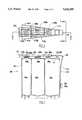
- FIG. 7is a side exterior view of a reagent container with a re-sealable lid of the invention in a closed position
- FIG. 8is a side exterior view of a reagent container with a re-sealable lid of the invention in an open position.
- the reagent container device and reagent container device system of the present inventionare a subsystem of an analytical instrument intended to produce reportable assay results through the processing of specimens and various other components of the chemistry system. This processing involves the control and timing of various internal operations as well as the acquisition and processing of data generated internally or through interaction with an external computer system such as LIS.
- the analytic instrumentis an integrated electromechanical apparatus which processes specimens in order to generate test results. It is comprised of all the mechanical hardware, electronic hardware and software required to perform either the chemical or the immunoassays desired.
- a reagent container 300 of the inventionwith its self-sealing lid mechanism 303 attached thereto.
- the container 300itself has a reagent vessel 301 comprised of a plurality of separate reagent storing compartments or wells, indicated as three compartments in this example of 301a, 301b, and 301c. These compartments share a common cover 314, which provides compartment openings 308a, 308b, and 308c, respectively.
- the openings 308a-chave a size adequate to permit a reagent extracting pipette (not shown) to be introduced into and retracted from the compartment in an unencumbered manner.
- the reagent containercan have any convenient geometric shape.
- the reagent container 300preferably is provided in an overall wedge-like shape, as indicated in the top view of FIG. 2, which allows a plurality of such reagent "wedges" to be situated side-by-side in a pie-like configuration on a carousel, thereby permitting a wide variety of reagents types to be accessible for immunoassay operations.
- the reagent compartmentscan be positioned in a linear array to provide an overall rectangular shaped reagent container.
- the reagent vessel 301can be prepackaged with its compartments pre-filled with selected reagents deposited in the various compartments.
- the openingscan be optionally pre-sealed with a detachable adhesive-coated metallic foil.
- the reagent containercan be loaded on a reagent carousel; sealing foil removed (if any); and then lid means 303 attached to the exterior of vessel 301, in a manner described in greater detail below.
- the lid means 303is a molded plastic member with spring-like biasing force generated by a bend 316 located below the hinge 307 that compels the lid means to release any bias force by movement of the horizontal arm 306 along the x-direction towards projection 310 until caps 309a-c cover openings 308a-c to return lid means 303 to a "closed" position (see FIG. 7).
- the arm 306displaces rearward in the direction of hinge 307 until caps 309a-c are pushed far enough to horizontally clear the underlying compartment openings 308a-c.
- the lid caps 309a-calternate with openings 315a-c.
- either the caps 309a-c or openings 315a-ccan be aligned with the underlying openings 308a-c in the cover 314 of the reagent vessels.
- the caps 309a-care sized slightly larger in diameter than openings 308a-c, respectively, such that the caps cover the openings when the lid means is in its normal position, versus its active position (described in greater detail below).
- a second hinge 313is provided at a location approximately midway between opening 315a and hinge 307.
- Hinges 307 and 313can be formed as thinned portions in the lid means 303 during its molding.
- the first hinge 307allows the arm 306 to generally slide forwards and backwards.
- the second hinge 313relieves stress created in the arm 306 when it is pushed backwards while traversing and restrained by the ramp guide means 51a, 51b (FIG.
- Both hinges 307 and 313are formed as thinned plastic regions in the arm molding which form flexure points along the arm 311 and arm 306, respectively. The thickness of the hinge must left sufficiently thick to prevent failure of the crimped or thinned hinge-like portion after only limited numbers of flexures.
- the lid means 303also is attached to the side wall 312 of reagent vessel 301 at its lower end.
- the lid means 303can be preassembled with the reagent vessel or attached on site when used. For example, when a fresh reagent wedge 300 is provided to a carousel of an immunoassay analyzer, the protective foil can be stripped from the upper surfaces of openings 308a-c to expose openings 308a-c, and the lid means 303 can be attached to the container before or after these steps.
- Another aspect of the reagent container sealing system 303 of this inventionis that the alternating caps 309a-c and openings 315a-c in the horizontal arm 306 of the lid means 303 are maintained in translational alignment over the underlying openings 308a-c of the reagent vessel compartments by use of guide means (not shown in FIG. 1 for sake of clarity as to other above-discussed features) to restrict sideways movement of the horizontal arm 306 during its movement over the upper surface of cover 314.
- ramp guide means 51a and 51bare provided on the upper surface of cover 314.
- the ramps 51a and 51b, and corresponding lid projections 52a and 52bare inclined at the same relatively small acute angle ⁇ relative to the horizontal plane P extending coplanar with the upper flat surface portion of cover 314, such as inclined from the horizontal direction (i.e., the x-direction) at angle ranging from about 5° to 15°, preferably about 10°.
- the direction of inclination of the ramp guide means 51a, 51bsteeps up from the front F of cover 314 towards the rear R of cover 314.
- the acute angle ⁇ established for ramps 51a and 5lb(and projections 52a and 52b)must be large enough such that as soon as lid means 303 is pushed rightward along the x-direction via force applied at projection 310 (in the perspective of FIG. 5), that the caps 309a-c of lid means 303 are contemporaneously translated upward up the ramps 51a and 51b and out of contact with the surfaces of the cap openings 308a-c of the cover 314.
- sliding friction between the cover 314 and lid means 303is avoided without resorting to a loose interfit of lid 303 and cover 314.
- the acute angle ⁇ of the ramps 51a and 51bmust be not be set too large so as to make access difficult to openings 309a-c of cover 314 when lid means 303 is pushed rightward along the x-direction via force applied at projection 310. That is, with an ever steeper angle for ramps 51a and 5lb, the horizontal profile of openings 315a-c in the lid 303 is diminished.
- the ratio of the vertical height H of the ramps 51a, 51b, relative to overall gap T between arm 306 and cover 314, that is, the ratio H/T,is about 40-50% for the highest point of each ramp and about 5-15% at the lowest end of each ramp.
- the arm 306, when horizontally displaced over the upper surface of cover 314,is mechanically guided by ramp means 51a, 51b via downward projections 52a, 52b on arm 305 having means to interconnect with the ramp means 51a, 51b while permitting intersliding movement along a single line of direction.
- interlockable hookscan be integrally formed on the ends of projections 52a, 52b and ramps 51a and 51b to allow slidable interfitting of these components.
- projection 52aactually is comprised of a pair of projections 152a and 152b located on opposite sides of the related cap 309a on arm 306.
- ramp guide means 51ais actually comprised of a pair of upstanding members 151a and 151b extending from cover 314 on either side of cover opening 308a.
- Projection 152blike its companion projection 152a, terminates in a downward projecting hook 521 which mechanically interfits with an upstanding hook or rail 511 formed in ramp guide portion 151b.
- an important aspect of the inventionis that when force is applied to projection 310 in the x-direction by an operator or electromechanical actuator, the projections 52a and 52b will slide up ramp guide means 51a and 5lb, respectively, avoiding sliding friction without resorting to loose interfit between the lid 303 and cover 314.
- projection 310is horizontally pushed with adequate force to overcome the normal opposing bias force in the lid means 303 caused by spring-arm 311 until caps 309a-c in the arm 306 clear compartment openings 308a-c and openings 315a-c instead align over the compartment openings 308a-c.
- the lower end of arm 311 of lid means 303can be attached to the sidewall 312 of the reagent vessel by any convenient means.
- the inner vertical wall 312 of the reagent vessel 301can have a sleeve 305 comprised of two upstanding walls 305a and 305b, which define an opening sized to receive tongue member 304 of arm 311 of lid 303, and a cover side 305c(see FIG. 1) integral with side walls 305a, 305b which prevents prevents movement of the arm off the sidewall 312.
- the tongue member 304has a pair of prongs 304a and 304b that are normally biased outward in the y-direction, but which can be displaced inward in the y-direction by operator handling.
- FIG. 4is a fragmentary view of the lid means 303 alone, where the labeled elements have the descriptions set forth herein.
- the prongs 304a and 304b of tongue 304 of the lid meansare inserted into the sleeve 305 through opening 313 to grip the respective walls 305a and 305b due to the outward spring-like bias of the prongs 304a and 304b, to attach the lid means 303 to the reagent vessel 301.
- Ribs or flangesalso can be formed on the inner sides of walls 305a and 305b of sleeve 305 to mechanically enhance the interlock between the tongue 304 and sleeve 305.
- the reagent wedgesi.e., "reagent packs" of the invention will simultaneously support a relatively large number of assay types, e.g., up to 24 or more, each requiring up to 3 or even more liquid reagents, without reduction of the on-board assay capacity of an automated chemical/biochemical analyzer.
- the reagent packs of the inventionalso provide the ability to store and preserve reagents on-board an immunoanalyzer, for example, for relatively extended periods of time, e.g. one month, without detectable degradation.
- the reagent packs of the inventionalso permit reagents to be positively identified via an attached bar code.
- a rotating carouselaccommodates a plurality of wedge-shaped reagent packs, each reagent pack capable of holding a plurality of different reagents in different compartments thereof.
- These packsinclude instrument actuated covers as well as vertical bar codes which are accessible to the specimen and diluent bar code reader.
- the entire carouselis housed within a refrigerator chamber maintained at about 4° C.
- the reagentsare supplied in liquid form, and are used to generate a detectable signal proportional or inversely proportional to the concentration of analyte in a specimen.
- theyare deposited into individual reaction tubes associated with a bead having an appropriate biomaterial coated on its surface for the test needed on the sample.
- Reagentsare contained within disposable packs, each bearing a plurality, e.g., up to three or more, different reagents in separate respective compartments. These packs protect their contents from the environment by virtue of their instrument actuated lids and their construction from colored transparent materials.
- the packsare also constructed of a material, such as plastic, that is sufficiently translucent to permit operators to visually observe from the outside the fluid levels within.
- a plurality, e.g., up to 24 or more, of different reagent packscan be simultaneously resident on the analyzer instrument, and the operator may replace or supplement the supply of packs at any time.
- a quantity of reagentmay be consumed from one or more of the chambers of a reagent pack for each test conducted.
- a particular reagent packmay be used for several different test types, but reagent/bead lot matching is required for each test type the reagent pack supports.
- a given testmust use reagents from one and only type of reagent pack. More than one pack of a given type may be resident on the analyzer instrument simultaneously.
- Reagent packsserve the following functions:
- Reagent packscan be bar code labeled with all the information needed to identify them to both an analyzer instrument and the operator.
- reaction tube load chainto a pipetting station for depositing the specimen (analyte of interest) and liquid reagent from a reagent container into the reaction tube (already containing the bead);
- An analyzer using the reagent container system and scheme of the present inventionrepresents a high throughput automated analyzer system capable of assaying a broad range of chemicals, or analytes in serum, plasma, and urine. It is also contemplated within the scope of the invention that specific chemistry kits might also handle clarified cerebrospinal fluid or saliva. Also, the system can impart a high degree of automation to a diverse set of immunoassays, such as encountered in hospital and commercial laboratory settings. As such, high volume testing (up to even 200 tests results per hour) is expected and must be accommodated. In addition, the urgency of medical decisions that will depend on the results of these assays dictates a rapid analytical response time.
- the reagent container systemhas been exemplified in terms of an immunoanalysis environment, it will be understood that the reagent container system of this invention has general applicability encompassing chemical reagent storage in general, as an individual device, or as used on board an automated chemical or biochemical analyzer.
Landscapes
- Health & Medical Sciences (AREA)
- Chemical & Material Sciences (AREA)
- Analytical Chemistry (AREA)
- General Health & Medical Sciences (AREA)
- Biochemistry (AREA)
- Physics & Mathematics (AREA)
- Life Sciences & Earth Sciences (AREA)
- General Physics & Mathematics (AREA)
- Immunology (AREA)
- Pathology (AREA)
- Clinical Laboratory Science (AREA)
- Chemical Kinetics & Catalysis (AREA)
- Hematology (AREA)
- Automatic Analysis And Handling Materials Therefor (AREA)
Abstract
Description
Claims (18)
Priority Applications (4)
| Application Number | Priority Date | Filing Date | Title |
|---|---|---|---|
| US08/670,994US5632399A (en) | 1996-06-28 | 1996-06-28 | Self-sealing reagent container and reagent container system |
| DE19781837TDE19781837T1 (en) | 1996-06-28 | 1997-06-27 | Automatic immunoassay analyzer |
| AU35827/97AAU3582797A (en) | 1996-06-28 | 1997-06-27 | Automated immunoassay analyzer |
| PCT/US1997/011245WO1998000697A1 (en) | 1996-06-28 | 1997-06-27 | Automated immunoassay analyzer |
Applications Claiming Priority (1)
| Application Number | Priority Date | Filing Date | Title |
|---|---|---|---|
| US08/670,994US5632399A (en) | 1996-06-28 | 1996-06-28 | Self-sealing reagent container and reagent container system |
Publications (1)
| Publication Number | Publication Date |
|---|---|
| US5632399Atrue US5632399A (en) | 1997-05-27 |
Family
ID=24692723
Family Applications (1)
| Application Number | Title | Priority Date | Filing Date |
|---|---|---|---|
| US08/670,994Expired - LifetimeUS5632399A (en) | 1996-06-28 | 1996-06-28 | Self-sealing reagent container and reagent container system |
Country Status (1)
| Country | Link |
|---|---|
| US (1) | US5632399A (en) |
Cited By (44)
| Publication number | Priority date | Publication date | Assignee | Title |
|---|---|---|---|---|
| WO1999052635A1 (en)* | 1998-04-10 | 1999-10-21 | Abbott Laboratories | Carrier with releasably fastened container retaining member and its use |
| US6056923A (en)* | 1997-06-25 | 2000-05-02 | Clmp, Inc. | Dual injector for chemiluminescence immunoanalyzing system |
| US6066296A (en)* | 1997-09-23 | 2000-05-23 | Array Medical, Inc. | Sample addition, reagent application, and testing chamber |
| USD427692S (en)* | 1998-06-30 | 2000-07-04 | Bayer Corporation | Plug for reagent package |
| WO2002064252A1 (en)* | 2001-02-15 | 2002-08-22 | Technische Universiteit Delft | Reaction plate with slidable cover and method to use the same |
| US6568552B1 (en)* | 1997-11-28 | 2003-05-27 | Mattson Technology, Inc. | Systems and methods for low contamination, high throughput handling of workpieces for vacuum processing |
| USD475917S1 (en) | 2002-07-08 | 2003-06-17 | Warner-Lambert Company | Dispenser |
| EP1132135A3 (en)* | 2000-03-09 | 2003-06-25 | Brand Gmbh + Co Kg | Individual closure and closure carrier for reaction wells, storage and dispensing device for individual closures |
| FR2837726A1 (en)* | 2002-03-26 | 2003-10-03 | Centre Nat Rech Scient | DEVICE AND COVER FOR ACCESSING SAMPLES OF A SAMPLE PLATE |
| US20040004083A1 (en)* | 2002-07-08 | 2004-01-08 | Bradford Grant | Hand held dispenser device |
| USD485490S1 (en) | 2002-07-08 | 2004-01-20 | Warner-Lambert Company Llc | Dispenser |
| USD485751S1 (en) | 2002-07-08 | 2004-01-27 | Warner-Lambert Company Llc | Dispenser |
| US20040110275A1 (en)* | 2002-12-04 | 2004-06-10 | Sandell Donald R | Sample substrate for use in biological testing and method for filling a sample substrate |
| USD491458S1 (en) | 2002-07-08 | 2004-06-15 | Warner-Lambert Company | Dispenser |
| USD491461S1 (en) | 2002-07-08 | 2004-06-15 | Warner-Lambert Company Llc | Dispenser |
| USD492898S1 (en) | 2002-07-08 | 2004-07-13 | Warner-Lambert Company Llc | Dispenser |
| USD492899S1 (en) | 2002-07-08 | 2004-07-13 | Warner-Lambert Company Llc | Dispenser |
| US20040171170A1 (en)* | 2003-02-28 | 2004-09-02 | Applera Corporation | Sample substrate having a divided sample chamber and method of loading thereof |
| USD499640S1 (en) | 2002-07-08 | 2004-12-14 | Warner-Lambert Company Llc | Dispenser |
| USD502093S1 (en) | 2003-06-16 | 2005-02-22 | Warner-Lambert Company Llc | Dispenser |
| USD505318S1 (en) | 2003-06-16 | 2005-05-24 | Warner-Lambert Company Llc | Dispenser |
| US20060245865A1 (en)* | 2005-03-24 | 2006-11-02 | Babson Arthur L | Carousel system for automated chemical or biological analyzers employing linear racks |
| USD590658S1 (en) | 2007-03-05 | 2009-04-21 | Richard Pola & Associates, Inc. | Cup with spritzing mechanism |
| US20090129987A1 (en)* | 2005-05-17 | 2009-05-21 | Wako Pure Chemical Industries, Ltd. | Connected Reagent Container |
| US20090129988A1 (en)* | 2007-02-08 | 2009-05-21 | Mark Talmer | Reagent Container Pack |
| US7607592B1 (en) | 2004-11-08 | 2009-10-27 | Kim Sang B | Accessories for water and beverage bottles |
| USD620603S1 (en) | 2007-02-08 | 2010-07-27 | Biokit S.A. | Reagent container pack |
| EP2371731A1 (en) | 2010-03-31 | 2011-10-05 | Roche Diagnostics GmbH | Reagent kit with transit support |
| JP2012047738A (en)* | 2010-08-24 | 2012-03-08 | Siemens Healthcare Diagnostics Products Gmbh | Sealing device for reagent container |
| US20120146477A1 (en)* | 2009-09-02 | 2012-06-14 | BSH Bosch und Siemens Hausgeräte GmbH | Refrigeration device with a vegetable drawer |
| CN103543281A (en)* | 2010-07-23 | 2014-01-29 | 贝克曼考尔特公司 | Automated analyzer and method |
| WO2014134331A1 (en)* | 2013-03-01 | 2014-09-04 | Siemens Healthcare Diagnostics Inc. | Self aligning wedge container with anti-evaporation tube |
| WO2015069546A3 (en)* | 2013-11-05 | 2015-11-12 | Siemens Healthcare Diagnostics Inc. | Multi-well wedge-shaped reagent container with auto-open capability |
| US9335338B2 (en) | 2013-03-15 | 2016-05-10 | Toshiba Medical Systems Corporation | Automated diagnostic analyzers having rear accessible track systems and related methods |
| US9400285B2 (en) | 2013-03-15 | 2016-07-26 | Abbot Laboratories | Automated diagnostic analyzers having vertically arranged carousels and related methods |
| US9535082B2 (en) | 2013-03-13 | 2017-01-03 | Abbott Laboratories | Methods and apparatus to agitate a liquid |
| JP2017075789A (en)* | 2015-10-13 | 2017-04-20 | 株式会社日立ハイテクノロジーズ | Automatic analysis device |
| US10001497B2 (en) | 2013-03-15 | 2018-06-19 | Abbott Laboratories | Diagnostic analyzers with pretreatment carousels and related methods |
| USD822224S1 (en) | 2013-03-13 | 2018-07-03 | Abbott Laboratories | Reagent kit with multiple bottles |
| US20210270860A1 (en)* | 2018-06-28 | 2021-09-02 | Fujifilm Wako Pure Chemical Corporation | Reagent storage device, reagent storage method, and shutter |
| USD962471S1 (en) | 2013-03-13 | 2022-08-30 | Abbott Laboratories | Reagent container |
| USD978375S1 (en) | 2013-03-13 | 2023-02-14 | Abbott Laboratories | Reagent container |
| US20230184797A1 (en)* | 2020-05-11 | 2023-06-15 | Hitachi High-Tech Corporation | Automatic Analyzer and Insertion Method of Reaction Container |
| USD1098486S1 (en) | 2022-08-03 | 2025-10-14 | Abbott Laboratories | Container for a diagnostic analyzer |
Citations (7)
| Publication number | Priority date | Publication date | Assignee | Title |
|---|---|---|---|---|
| US1162791A (en)* | 1915-08-16 | 1915-12-07 | Mike Lubas | Ink-well. |
| US3169679A (en)* | 1963-12-06 | 1965-02-16 | Bernard A Hunter | Closure for top perforated cans |
| US3392060A (en)* | 1966-04-27 | 1968-07-09 | Phillips Petroleum Co | Quick-opening battery cap closure |
| US4673813A (en)* | 1985-05-30 | 1987-06-16 | Nuclear Medical Products, Inc. | Multi-dose radio-isotope container |
| US4718570A (en)* | 1986-04-05 | 1988-01-12 | Vita Zahnfabrik H. Rauter Gmbh & Co. | Dispenser for pasty compositions |
| US5282543A (en)* | 1990-11-29 | 1994-02-01 | The Perkin Elmer Corporation | Cover for array of reaction tubes |
| US5316726A (en)* | 1991-07-26 | 1994-05-31 | Cirrus Diagnostics, Inc. | Automated immunoassay analyzer with pictorial display of assay information |
- 1996
- 1996-06-28USUS08/670,994patent/US5632399A/ennot_activeExpired - Lifetime
Patent Citations (7)
| Publication number | Priority date | Publication date | Assignee | Title |
|---|---|---|---|---|
| US1162791A (en)* | 1915-08-16 | 1915-12-07 | Mike Lubas | Ink-well. |
| US3169679A (en)* | 1963-12-06 | 1965-02-16 | Bernard A Hunter | Closure for top perforated cans |
| US3392060A (en)* | 1966-04-27 | 1968-07-09 | Phillips Petroleum Co | Quick-opening battery cap closure |
| US4673813A (en)* | 1985-05-30 | 1987-06-16 | Nuclear Medical Products, Inc. | Multi-dose radio-isotope container |
| US4718570A (en)* | 1986-04-05 | 1988-01-12 | Vita Zahnfabrik H. Rauter Gmbh & Co. | Dispenser for pasty compositions |
| US5282543A (en)* | 1990-11-29 | 1994-02-01 | The Perkin Elmer Corporation | Cover for array of reaction tubes |
| US5316726A (en)* | 1991-07-26 | 1994-05-31 | Cirrus Diagnostics, Inc. | Automated immunoassay analyzer with pictorial display of assay information |
Non-Patent Citations (2)
| Title |
|---|
| Trade Brochure, entitled "PK310 Fully Automated Enzyme Analyser", a publication of Olympus Biomedical Products Div., Wendenstrasse 14-16, 2 Hamburg 1, Germany, 15 pages, undated. |
| Trade Brochure, entitled PK310 Fully Automated Enzyme Analyser , a publication of Olympus Biomedical Products Div., Wendenstrasse 14 16, 2 Hamburg 1, Germany, 15 pages, undated.* |
Cited By (100)
| Publication number | Priority date | Publication date | Assignee | Title |
|---|---|---|---|---|
| US6056923A (en)* | 1997-06-25 | 2000-05-02 | Clmp, Inc. | Dual injector for chemiluminescence immunoanalyzing system |
| US6066296A (en)* | 1997-09-23 | 2000-05-23 | Array Medical, Inc. | Sample addition, reagent application, and testing chamber |
| US6568552B1 (en)* | 1997-11-28 | 2003-05-27 | Mattson Technology, Inc. | Systems and methods for low contamination, high throughput handling of workpieces for vacuum processing |
| WO1999052635A1 (en)* | 1998-04-10 | 1999-10-21 | Abbott Laboratories | Carrier with releasably fastened container retaining member and its use |
| USD427692S (en)* | 1998-06-30 | 2000-07-04 | Bayer Corporation | Plug for reagent package |
| EP1132135A3 (en)* | 2000-03-09 | 2003-06-25 | Brand Gmbh + Co Kg | Individual closure and closure carrier for reaction wells, storage and dispensing device for individual closures |
| US20040142479A1 (en)* | 2001-02-15 | 2004-07-22 | Robert Moerman | Reaction plate with slidable cover and method to use the same |
| WO2002064252A1 (en)* | 2001-02-15 | 2002-08-22 | Technische Universiteit Delft | Reaction plate with slidable cover and method to use the same |
| FR2837726A1 (en)* | 2002-03-26 | 2003-10-03 | Centre Nat Rech Scient | DEVICE AND COVER FOR ACCESSING SAMPLES OF A SAMPLE PLATE |
| USD492898S1 (en) | 2002-07-08 | 2004-07-13 | Warner-Lambert Company Llc | Dispenser |
| USD493713S1 (en) | 2002-07-08 | 2004-08-03 | Warner-Lambert Company Llc | Dispenser |
| USD485751S1 (en) | 2002-07-08 | 2004-01-27 | Warner-Lambert Company Llc | Dispenser |
| USD475917S1 (en) | 2002-07-08 | 2003-06-17 | Warner-Lambert Company | Dispenser |
| USD491458S1 (en) | 2002-07-08 | 2004-06-15 | Warner-Lambert Company | Dispenser |
| USD491459S1 (en) | 2002-07-08 | 2004-06-15 | Warner-Lambert Company Llc | Dispenser |
| USD491460S1 (en) | 2002-07-08 | 2004-06-15 | Warner-Lambert Company Llc | Dispenser |
| USD491462S1 (en) | 2002-07-08 | 2004-06-15 | Warner-Lambert Company Llc | Dispenser |
| USD491461S1 (en) | 2002-07-08 | 2004-06-15 | Warner-Lambert Company Llc | Dispenser |
| USD499640S1 (en) | 2002-07-08 | 2004-12-14 | Warner-Lambert Company Llc | Dispenser |
| USD492899S1 (en) | 2002-07-08 | 2004-07-13 | Warner-Lambert Company Llc | Dispenser |
| USD493102S1 (en) | 2002-07-08 | 2004-07-20 | Warner-Lambert Company Llc | Dispenser |
| USD493103S1 (en) | 2002-07-08 | 2004-07-20 | Warner-Lambert Company Llc | Dispenser |
| US20040004083A1 (en)* | 2002-07-08 | 2004-01-08 | Bradford Grant | Hand held dispenser device |
| USD493712S1 (en) | 2002-07-08 | 2004-08-03 | Warner-Lambert Company Llc | Dispenser |
| USD485490S1 (en) | 2002-07-08 | 2004-01-20 | Warner-Lambert Company Llc | Dispenser |
| US20040110275A1 (en)* | 2002-12-04 | 2004-06-10 | Sandell Donald R | Sample substrate for use in biological testing and method for filling a sample substrate |
| US7169602B2 (en) | 2002-12-04 | 2007-01-30 | Applera Corporation | Sample substrate for use in biological testing and method for filling a sample substrate |
| US20070122912A1 (en)* | 2002-12-04 | 2007-05-31 | Applera Corporation | Sample Substrate for Use in Biological Testing and Method for Filling a Sample Substrate |
| US7332348B2 (en) | 2003-02-28 | 2008-02-19 | Applera Corporation | Sample substrate having a divided sample chamber and method of loading thereof |
| US20080267829A1 (en)* | 2003-02-28 | 2008-10-30 | Applera Corporation | Sample Substrate Having a Divided Sample Chamber and Method of Loading Thereof |
| US20040171170A1 (en)* | 2003-02-28 | 2004-09-02 | Applera Corporation | Sample substrate having a divided sample chamber and method of loading thereof |
| US8628730B2 (en) | 2003-02-28 | 2014-01-14 | Applied Biosystems, Llc | Sample substrate having a divided sample chamber and method of loading thereof |
| USD502093S1 (en) | 2003-06-16 | 2005-02-22 | Warner-Lambert Company Llc | Dispenser |
| USD505318S1 (en) | 2003-06-16 | 2005-05-24 | Warner-Lambert Company Llc | Dispenser |
| US7607592B1 (en) | 2004-11-08 | 2009-10-27 | Kim Sang B | Accessories for water and beverage bottles |
| US7670553B2 (en) | 2005-03-24 | 2010-03-02 | Siemens Healthcare Diagnostics Inc. | Carousel system for automated chemical or biological analyzers employing linear racks |
| US20060245865A1 (en)* | 2005-03-24 | 2006-11-02 | Babson Arthur L | Carousel system for automated chemical or biological analyzers employing linear racks |
| US20090129987A1 (en)* | 2005-05-17 | 2009-05-21 | Wako Pure Chemical Industries, Ltd. | Connected Reagent Container |
| US8728413B2 (en) | 2007-02-08 | 2014-05-20 | Biokit, S.A. | Reagent container pack |
| AU2009314184B2 (en)* | 2007-02-08 | 2013-12-12 | Biokit, S.A. | Reagent container pack |
| USD620603S1 (en) | 2007-02-08 | 2010-07-27 | Biokit S.A. | Reagent container pack |
| US9383296B2 (en) | 2007-02-08 | 2016-07-05 | Biokit, S.A. | Reagent container pack |
| US20090129988A1 (en)* | 2007-02-08 | 2009-05-21 | Mark Talmer | Reagent Container Pack |
| USD590658S1 (en) | 2007-03-05 | 2009-04-21 | Richard Pola & Associates, Inc. | Cup with spritzing mechanism |
| JP2012508885A (en)* | 2008-11-14 | 2012-04-12 | バイオキット,エス.アー. | Reagent container pack |
| WO2010056701A1 (en)* | 2008-11-14 | 2010-05-20 | Biokit S.A. | Reagent container pack |
| US9677806B2 (en)* | 2009-09-02 | 2017-06-13 | BSH Hausgeräte GmbH | Refrigeration device with a vegetable drawer |
| US20120146477A1 (en)* | 2009-09-02 | 2012-06-14 | BSH Bosch und Siemens Hausgeräte GmbH | Refrigeration device with a vegetable drawer |
| WO2011121030A1 (en) | 2010-03-31 | 2011-10-06 | Roche Diagnostics Gmbh | A reagent kit with in-transit securing means |
| JP2013524190A (en)* | 2010-03-31 | 2013-06-17 | エフ.ホフマン−ラ ロシュ アーゲー | Reagent kit with fixing means during transportation |
| CN102811918B (en)* | 2010-03-31 | 2014-10-29 | 霍夫曼-拉罗奇有限公司 | A reagent kit with in-transit securing means |
| US8906321B2 (en) | 2010-03-31 | 2014-12-09 | Roche Diagnostics Operations, Inc. | Reagent kit with in-transit securing means |
| CN102811918A (en)* | 2010-03-31 | 2012-12-05 | 霍夫曼-拉罗奇有限公司 | Kits with In-Transit Fastening Mechanisms |
| EP2371731A1 (en) | 2010-03-31 | 2011-10-05 | Roche Diagnostics GmbH | Reagent kit with transit support |
| CN103543281A (en)* | 2010-07-23 | 2014-01-29 | 贝克曼考尔特公司 | Automated analyzer and method |
| US8840848B2 (en) | 2010-07-23 | 2014-09-23 | Beckman Coulter, Inc. | System and method including analytical units |
| JP2012047738A (en)* | 2010-08-24 | 2012-03-08 | Siemens Healthcare Diagnostics Products Gmbh | Sealing device for reagent container |
| WO2014134331A1 (en)* | 2013-03-01 | 2014-09-04 | Siemens Healthcare Diagnostics Inc. | Self aligning wedge container with anti-evaporation tube |
| US10500589B2 (en)* | 2013-03-01 | 2019-12-10 | Siemens Healthcare Diagnostics Inc. | Self aligning wedge container with anti-evaporation tube |
| US20160016162A1 (en)* | 2013-03-01 | 2016-01-21 | Siemens Healthcare Diagnostics Inc. | Self aligning wedge container with anti-evaporation tube |
| CN108325439A (en)* | 2013-03-13 | 2018-07-27 | 雅培制药有限公司 | Mitigate the method and apparatus of the bubble formation in liquid |
| USD962471S1 (en) | 2013-03-13 | 2022-08-30 | Abbott Laboratories | Reagent container |
| US9535082B2 (en) | 2013-03-13 | 2017-01-03 | Abbott Laboratories | Methods and apparatus to agitate a liquid |
| CN114950220B (en)* | 2013-03-13 | 2024-07-26 | 雅培制药有限公司 | Method and apparatus for mitigating bubble formation in a liquid |
| US11738346B2 (en) | 2013-03-13 | 2023-08-29 | Abbott Laboratories | Methods and apparatus to mitigate bubble formation in a liquid |
| US9789454B2 (en) | 2013-03-13 | 2017-10-17 | Abbott Laboratories | Methods and apparatus to agitate a liquid |
| US11712671B2 (en) | 2013-03-13 | 2023-08-01 | Abbott Laboratories | Methods and apparatus to agitate a liquid |
| USD815299S1 (en) | 2013-03-13 | 2018-04-10 | Abbott Laboratories | Reagent kit with multiple bottles |
| USD978375S1 (en) | 2013-03-13 | 2023-02-14 | Abbott Laboratories | Reagent container |
| USD822224S1 (en) | 2013-03-13 | 2018-07-03 | Abbott Laboratories | Reagent kit with multiple bottles |
| CN114950220A (en)* | 2013-03-13 | 2022-08-30 | 雅培制药有限公司 | Method and apparatus for mitigating bubble formation in a liquid |
| US10058866B2 (en) | 2013-03-13 | 2018-08-28 | Abbott Laboratories | Methods and apparatus to mitigate bubble formation in a liquid |
| US20180353964A1 (en)* | 2013-03-13 | 2018-12-13 | Abbott Laboratories | Methods and apparatus to mitigate bubble formation in a liquid |
| JP2022106936A (en)* | 2013-03-13 | 2022-07-20 | アボット・ラボラトリーズ | Methods and apparatus to mitigate bubble formation in liquid |
| JP2021043208A (en)* | 2013-03-13 | 2021-03-18 | アボット・ラボラトリーズAbbott Laboratories | Methods and devices for reducing bubble formation in liquids |
| US10926263B2 (en) | 2013-03-13 | 2021-02-23 | Abbott Laboratories | Methods and apparatus to mitigate bubble formation in a liquid |
| USD875269S1 (en) | 2013-03-13 | 2020-02-11 | Abbott Laboratories | Reagent kit with multiple bottles |
| USD875270S1 (en) | 2013-03-13 | 2020-02-11 | Abbott Laboratories | Reagent kit with multiple bottles |
| US10639600B2 (en) | 2013-03-13 | 2020-05-05 | Abbott Laboratories | Methods and apparatus to agitate a liquid |
| USD892350S1 (en) | 2013-03-13 | 2020-08-04 | Abbott Laboratories | Reagent kit frame |
| USD905866S1 (en) | 2013-03-13 | 2020-12-22 | Abbott Laboratories | Reagent kit frame |
| US11435372B2 (en) | 2013-03-15 | 2022-09-06 | Abbott Laboratories | Diagnostic analyzers with pretreatment carousels and related methods |
| US10001497B2 (en) | 2013-03-15 | 2018-06-19 | Abbott Laboratories | Diagnostic analyzers with pretreatment carousels and related methods |
| US10267818B2 (en) | 2013-03-15 | 2019-04-23 | Abbott Laboratories | Automated diagnostic analyzers having rear accessible track systems and related methods |
| US11536739B2 (en) | 2013-03-15 | 2022-12-27 | Abbott Laboratories | Automated diagnostic analyzers having vertically arranged carousels and related methods |
| US11125766B2 (en) | 2013-03-15 | 2021-09-21 | Abbott Laboratories | Automated diagnostic analyzers having rear accessible track systems and related methods |
| US10197585B2 (en) | 2013-03-15 | 2019-02-05 | Abbott Laboratories | Automated diagnostic analyzers having vertically arranged carousels and related methods |
| US9335338B2 (en) | 2013-03-15 | 2016-05-10 | Toshiba Medical Systems Corporation | Automated diagnostic analyzers having rear accessible track systems and related methods |
| US12228583B2 (en) | 2013-03-15 | 2025-02-18 | Abbott Laboratories | Automated diagnostic analyzers having vertically arranged carousels and related methods |
| US12007403B2 (en) | 2013-03-15 | 2024-06-11 | Abbott Laboratories | Automated diagnostic analyzers having rear accessible track systems and related methods |
| US10775398B2 (en) | 2013-03-15 | 2020-09-15 | Abbott Laboratories | Automated diagnostic analyzers having vertically arranged carousels and related methods |
| US9400285B2 (en) | 2013-03-15 | 2016-07-26 | Abbot Laboratories | Automated diagnostic analyzers having vertically arranged carousels and related methods |
| US9823261B2 (en)* | 2013-11-05 | 2017-11-21 | Siemens Healthcare Diagnostics Inc. | Multi-well wedge-shaped reagent container with auto-open capability |
| WO2015069546A3 (en)* | 2013-11-05 | 2015-11-12 | Siemens Healthcare Diagnostics Inc. | Multi-well wedge-shaped reagent container with auto-open capability |
| US20160266155A1 (en)* | 2013-11-05 | 2016-09-15 | Siemens Healthcare Diagnostics Inc. | Multi-well wedge-shaped reagent container with auto-open capability |
| JP2017075789A (en)* | 2015-10-13 | 2017-04-20 | 株式会社日立ハイテクノロジーズ | Automatic analysis device |
| US20210270860A1 (en)* | 2018-06-28 | 2021-09-02 | Fujifilm Wako Pure Chemical Corporation | Reagent storage device, reagent storage method, and shutter |
| US11782066B2 (en)* | 2018-06-28 | 2023-10-10 | Fujifilm Wako Pure Chemical Corporation | Reagent storage device, reagent storage method, and shutter |
| US20230184797A1 (en)* | 2020-05-11 | 2023-06-15 | Hitachi High-Tech Corporation | Automatic Analyzer and Insertion Method of Reaction Container |
| USD1098486S1 (en) | 2022-08-03 | 2025-10-14 | Abbott Laboratories | Container for a diagnostic analyzer |
Similar Documents
| Publication | Publication Date | Title |
|---|---|---|
| US5632399A (en) | Self-sealing reagent container and reagent container system | |
| US12153061B2 (en) | Cartridge assembly tray for immunoassay tests | |
| US5885529A (en) | Automated immunoassay analyzer | |
| EP0204109B1 (en) | A self-contained reagent package device for an assay | |
| US5167922A (en) | Assay cartridge | |
| DK2031406T3 (en) | Automatic analyzer for several purposes for in-vitro diagnostic | |
| US8728413B2 (en) | Reagent container pack | |
| EP2192411A1 (en) | System and method for the processing of liquid samples | |
| EP0521299A2 (en) | Reagent bottle and cap | |
| WO1998000697A1 (en) | Automated immunoassay analyzer | |
| EP2743703B1 (en) | Method for holding multiple types of diagnostic test consumables in a random access single container | |
| US9731847B2 (en) | Method for holding multiple types of diagnostic test consumables in a random access single container | |
| US9823261B2 (en) | Multi-well wedge-shaped reagent container with auto-open capability | |
| JPH08506893A (en) | Solid phase immunoassay with a carrier that conforms to the shape of the sample well | |
| US5773296A (en) | Bead dispenser and bead dispenser system for immunoassay analysis | |
| WO2002037078A2 (en) | Automated immunoassay analyzer and method of using the same | |
| JPH06509175A (en) | Reagent processing system for medical automatic analyzers | |
| AU2013257454B2 (en) | Reagent container pack |
Legal Events
| Date | Code | Title | Description |
|---|---|---|---|
| AS | Assignment | Owner name:DPC CIRRUS INC., NEW JERSEY Free format text:ASSIGNMENT OF ASSIGNORS INTEREST;ASSIGNORS:PALMIERI, THOMAS;BABSON, ARTHUR L.;REEL/FRAME:008087/0314 Effective date:19960627 | |
| STCF | Information on status: patent grant | Free format text:PATENTED CASE | |
| FEPP | Fee payment procedure | Free format text:PAYOR NUMBER ASSIGNED (ORIGINAL EVENT CODE: ASPN); ENTITY STATUS OF PATENT OWNER: LARGE ENTITY | |
| FPAY | Fee payment | Year of fee payment:4 | |
| FPAY | Fee payment | Year of fee payment:8 | |
| FEPP | Fee payment procedure | Free format text:PAYER NUMBER DE-ASSIGNED (ORIGINAL EVENT CODE: RMPN); ENTITY STATUS OF PATENT OWNER: LARGE ENTITY Free format text:PAYOR NUMBER ASSIGNED (ORIGINAL EVENT CODE: ASPN); ENTITY STATUS OF PATENT OWNER: LARGE ENTITY | |
| AS | Assignment | Owner name:SIEMENS MEDICAL SOLUTIONS DIAGNOSTICS, NEW YORK Free format text:CHANGE OF NAME;ASSIGNOR:DPC CIRRUS, INC.;REEL/FRAME:019440/0617 Effective date:20061227 | |
| AS | Assignment | Owner name:SIEMENS HEALTHCARE DIAGNOSTICS INC., NEW YORK Free format text:CHANGE OF NAME;ASSIGNOR:SIEMENS MEDICAL SOLUTIONS DIAGNOSTICS;REEL/FRAME:021423/0942 Effective date:20071231 | |
| FPAY | Fee payment | Year of fee payment:12 |