US5631920A - Spread spectrum clock generator - Google Patents
Spread spectrum clock generatorDownload PDFInfo
- Publication number
- US5631920A US5631920AUS08/425,832US42583295AUS5631920AUS 5631920 AUS5631920 AUS 5631920AUS 42583295 AUS42583295 AUS 42583295AUS 5631920 AUS5631920 AUS 5631920A
- Authority
- US
- United States
- Prior art keywords
- clock
- counter
- spread spectrum
- input
- signal
- Prior art date
- Legal status (The legal status is an assumption and is not a legal conclusion. Google has not performed a legal analysis and makes no representation as to the accuracy of the status listed.)
- Expired - Lifetime
Links
- 238000001228spectrumMethods0.000titleclaimsabstractdescription51
- 230000003595spectral effectEffects0.000abstractdescription16
- 230000001360synchronised effectEffects0.000abstractdescription6
- 230000000737periodic effectEffects0.000description5
- 230000008859changeEffects0.000description4
- 239000013078crystalSubstances0.000description4
- 238000010586diagramMethods0.000description4
- 230000006870functionEffects0.000description4
- 230000009467reductionEffects0.000description4
- 230000008901benefitEffects0.000description3
- 238000000034methodMethods0.000description3
- 238000013459approachMethods0.000description2
- 238000012986modificationMethods0.000description2
- 230000004048modificationEffects0.000description2
- 230000001105regulatory effectEffects0.000description2
- 230000001629suppressionEffects0.000description2
- 230000033228biological regulationEffects0.000description1
- 230000015556catabolic processEffects0.000description1
- 238000004891communicationMethods0.000description1
- 238000006731degradation reactionMethods0.000description1
- 230000001419dependent effectEffects0.000description1
- 230000000694effectsEffects0.000description1
- 238000010894electron beam technologyMethods0.000description1
- 230000003993interactionEffects0.000description1
- 238000005259measurementMethods0.000description1
- ZYHMJXZULPZUED-UHFFFAOYSA-NpropargiteChemical compoundC1=CC(C(C)(C)C)=CC=C1OC1C(OS(=O)OCC#C)CCCC1ZYHMJXZULPZUED-UHFFFAOYSA-N0.000description1
- 238000010408sweepingMethods0.000description1
- 238000012956testing procedureMethods0.000description1
Images


Classifications
- H—ELECTRICITY
- H03—ELECTRONIC CIRCUITRY
- H03C—MODULATION
- H03C3/00—Angle modulation
- H03C3/02—Details
- H03C3/09—Modifications of modulator for regulating the mean frequency
- H03C3/0908—Modifications of modulator for regulating the mean frequency using a phase locked loop
- H03C3/0966—Modifications of modulator for regulating the mean frequency using a phase locked loop modulating the reference clock
- H—ELECTRICITY
- H03—ELECTRONIC CIRCUITRY
- H03B—GENERATION OF OSCILLATIONS, DIRECTLY OR BY FREQUENCY-CHANGING, BY CIRCUITS EMPLOYING ACTIVE ELEMENTS WHICH OPERATE IN A NON-SWITCHING MANNER; GENERATION OF NOISE BY SUCH CIRCUITS
- H03B29/00—Generation of noise currents and voltages
- H—ELECTRICITY
- H03—ELECTRONIC CIRCUITRY
- H03C—MODULATION
- H03C3/00—Angle modulation
- H03C3/02—Details
- H03C3/09—Modifications of modulator for regulating the mean frequency
- H03C3/0908—Modifications of modulator for regulating the mean frequency using a phase locked loop
- H03C3/0916—Modifications of modulator for regulating the mean frequency using a phase locked loop with frequency divider or counter in the loop
- H03C3/0925—Modifications of modulator for regulating the mean frequency using a phase locked loop with frequency divider or counter in the loop applying frequency modulation at the divider in the feedback loop
- H—ELECTRICITY
- H03—ELECTRONIC CIRCUITRY
- H03C—MODULATION
- H03C3/00—Angle modulation
- H03C3/02—Details
- H03C3/09—Modifications of modulator for regulating the mean frequency
- H03C3/0908—Modifications of modulator for regulating the mean frequency using a phase locked loop
- H03C3/0941—Modifications of modulator for regulating the mean frequency using a phase locked loop applying frequency modulation at more than one point in the loop
- H—ELECTRICITY
- H03—ELECTRONIC CIRCUITRY
- H03L—AUTOMATIC CONTROL, STARTING, SYNCHRONISATION OR STABILISATION OF GENERATORS OF ELECTRONIC OSCILLATIONS OR PULSES
- H03L7/00—Automatic control of frequency or phase; Synchronisation
- H03L7/06—Automatic control of frequency or phase; Synchronisation using a reference signal applied to a frequency- or phase-locked loop
- H03L7/07—Automatic control of frequency or phase; Synchronisation using a reference signal applied to a frequency- or phase-locked loop using several loops, e.g. for redundant clock signal generation
- H—ELECTRICITY
- H03—ELECTRONIC CIRCUITRY
- H03L—AUTOMATIC CONTROL, STARTING, SYNCHRONISATION OR STABILISATION OF GENERATORS OF ELECTRONIC OSCILLATIONS OR PULSES
- H03L7/00—Automatic control of frequency or phase; Synchronisation
- H03L7/06—Automatic control of frequency or phase; Synchronisation using a reference signal applied to a frequency- or phase-locked loop
- H03L7/08—Details of the phase-locked loop
- H03L7/0805—Details of the phase-locked loop the loop being adapted to provide an additional control signal for use outside the loop
- H—ELECTRICITY
- H03—ELECTRONIC CIRCUITRY
- H03L—AUTOMATIC CONTROL, STARTING, SYNCHRONISATION OR STABILISATION OF GENERATORS OF ELECTRONIC OSCILLATIONS OR PULSES
- H03L7/00—Automatic control of frequency or phase; Synchronisation
- H03L7/06—Automatic control of frequency or phase; Synchronisation using a reference signal applied to a frequency- or phase-locked loop
- H03L7/08—Details of the phase-locked loop
- H03L7/085—Details of the phase-locked loop concerning mainly the frequency- or phase-detection arrangement including the filtering or amplification of its output signal
- H03L7/087—Details of the phase-locked loop concerning mainly the frequency- or phase-detection arrangement including the filtering or amplification of its output signal using at least two phase detectors or a frequency and phase detector in the loop
- H—ELECTRICITY
- H03—ELECTRONIC CIRCUITRY
- H03L—AUTOMATIC CONTROL, STARTING, SYNCHRONISATION OR STABILISATION OF GENERATORS OF ELECTRONIC OSCILLATIONS OR PULSES
- H03L7/00—Automatic control of frequency or phase; Synchronisation
- H03L7/06—Automatic control of frequency or phase; Synchronisation using a reference signal applied to a frequency- or phase-locked loop
- H03L7/16—Indirect frequency synthesis, i.e. generating a desired one of a number of predetermined frequencies using a frequency- or phase-locked loop
- H03L7/18—Indirect frequency synthesis, i.e. generating a desired one of a number of predetermined frequencies using a frequency- or phase-locked loop using a frequency divider or counter in the loop
- H03L7/197—Indirect frequency synthesis, i.e. generating a desired one of a number of predetermined frequencies using a frequency- or phase-locked loop using a frequency divider or counter in the loop a time difference being used for locking the loop, the counter counting between numbers which are variable in time or the frequency divider dividing by a factor variable in time, e.g. for obtaining fractional frequency division
- H—ELECTRICITY
- H04—ELECTRIC COMMUNICATION TECHNIQUE
- H04B—TRANSMISSION
- H04B2215/00—Reducing interference at the transmission system level
- H04B2215/064—Reduction of clock or synthesizer reference frequency harmonics
- H—ELECTRICITY
- H04—ELECTRIC COMMUNICATION TECHNIQUE
- H04B—TRANSMISSION
- H04B2215/00—Reducing interference at the transmission system level
- H04B2215/064—Reduction of clock or synthesizer reference frequency harmonics
- H04B2215/067—Reduction of clock or synthesizer reference frequency harmonics by modulation dispersion
Definitions
- This inventionrelates to the field of digital circuits, and more particularly, to a clock circuit having reduced measurable electromagnetic interference (EMI) emissions.
- EMIelectromagnetic interference
- a clock signalpermits the precise timing of events in the microprocessor, for example.
- Typical microprocessorsmay be supervised or synchronized by a free-running oscillator, such as driven by a crystal, an LC-tuned circuit, or an external clock source. Clocking rates up to and beyond 40 MHz are common in personal computers.
- the parameters of a clock signalare typically specified for a microprocessor and may include minimum and maximum allowable clock frequencies, tolerances on the high and low voltage levels, maximum rise and fall times on the waveform edges, pulse-width tolerance if the waveform is not a square wave, and the timing relationship between clock phases if two-clock phase signals are needed. (See Electronics Engineers' Handbook, by Fink et al., p. 8-111, 1989.)
- EMIelectromagnetic interference
- the spectral components of the EMI emissionstypically have peak amplitudes at harmonics of the fundamental frequency of the clock circuit.
- regulatory agenciessuch as the FCC in the United States, have established testing procedures and maximum allowable emissions for such products.
- the Commission Electrotechnique InternationalCommission International Special Des Perturbations Radiocies (C.I.S.P.R.)
- C.I.S.P.R.Commission Electrotechnique International
- the measured 6 dB bandwidthis a relatively wide 120 KHz.
- digital spread spectrum modulation circuitsare preferably used. These circuits are synchronized by resetting a counter which controls the circuit.
- Spread spectrum clock implementations employing a voltage controlled oscillator but not digital controlare disclosed in U.S Pat. No. 4,507,796 to Stumfall.
- Digital control circuits of some similarity, not for spread spectrum clock controlare disclosed in U.S. Pat. No. 3,764,933 to Fletcher et al, U.S. Pat. No.
- a clock circuitincluding an oscillator for generating a reference frequency signal, and spread spectrum clock generating means for generating a spread spectrum clock output signal having a fundamental or center frequency and reduced amplitude EMI spectral components at harmonics of the fundamental frequency.
- the spread spectrum clock generating meanspreferably includes clock pulse generating means for generating a series of clock pulses, and spread spectrum modulating means for modulating the clock pulse generating means to broaden and flatten amplitudes of EMI spectral components which would otherwise be produced by the clock pulse generating means. A starting point in such modulation is precisely controllable to facilitate synchronization.
- the clock pulse generating meansif unmodulated, would typically produce generally rectangular or trapezoidal electrical pulses which, in turn, would generate corresponding impulse-shaped EMI spectral components at harmonics of the fundamental frequency.
- the spread spectrum modulating meansreduces the peak amplitude of the EMI spectral components that would otherwise be produced. Accordingly, expensive shielding or other EMI suppression techniques may be reduced or eliminated in an electronic device including the spread spectrum clock generating circuit of the present invention.
- the spread spectrum clock generating circuitmay find wide application in a number of electronic devices, particularly those including a microprocessor or microcontroller, such as a personal computer.
- the spread spectrum modulating meanspreferably includes frequency modulating means for frequency modulating the clock pulse generating means.
- the frequency modulating meansin turn, preferably includes profile modulating means for frequency modulating the clock pulse generating means with a periodic waveform having a predetermined period and a predetermined frequency deviation profile as a function of the predetermined period.
- profile modulating meansfor frequency modulating the clock pulse generating means with a periodic waveform having a predetermined period and a predetermined frequency deviation profile as a function of the predetermined period.
- the clock pulse generating meanspreferably includes a phase locked loop as is commonly used in a conventional clock generating circuit.
- the frequency modulation meansmay be implemented by a programmable modulating generator which can produce a predetermined profile for the frequency deviation.
- the frequency modulating meansis preferably capable of modulating the clock pulse generating means with a periodic waveform having a period of less than about 500 microseconds, that is, the frequency of modulation is desirably greater than about 2 KHz.
- FIG. 1is a schematic block diagram of a personal computer including a spread spectrum clock generating circuit in accordance with the invention.
- FIG. 2is a graph illustrating a reduction of peak spectral amplitude of a harmonic of the clock fundamental frequency produced by the spread spectrum clock generating circuit in accordance with the present invention.
- FIG. 3is a graph illustrating an embodiment of a desired modulation profile for producing a spread spectrum modulated clock signal in accordance with the present invention.
- FIG. 4is a graph illustrating several modulation profile ranges for producing a spread spectrum modulated clock output signal in accordance with the present invention.
- FIG. 5is a graph illustrating yet another embodiment of a desired modulation profile for producing a spread spectrum modulated clock output signal in accordance with the present invention.
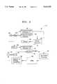
- FIG. 6is a schematic block diagram illustrating a circuit embodiment for producing the precisely controlled spread spectrum modulated clock output signal in accordance with the present invention.
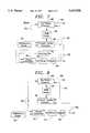
- FIG. 7is a schematic block diagram illustrating another embodiment for producing a precisely controlled spread spectrum modulated clock output signal in accordance with the present invention.
- FIG. 8is a variation of the circuit of FIG. 7 eliminating one counter.
- an electronic devicesuch as the schematically illustrated personal computer 10 may benefit by having reduced measurable EMI spectral component emissions provided by the spread spectrum clock generator 14 (SSCG) according to the invention.
- a reference frequency generator 15such as a piezoelectric crystal driven at its resonant frequency by a suitable driver or oscillator circuit, provides a reference frequency for the SSCG14.
- the illustrated personal computer 10also includes a display 12 and a keyboard 13.
- a number of electronic devices incorporating microprocessors or other digital circuits requiring a clock signal for synchronizationmay also desirably incorporate the SSCG14.
- computer printersmay also desirably include the SSCG 14.
- the SSCG 14generates the spread spectrum output clock signal by frequency modulating a typical clock signal including a series of trapezoidal or generally rectangularly-shaped electrical dock pulses.
- the modulationreduces the spectral amplitude of the EMI components at each harmonic of the clock when compared to the spectrum of the same clocking signal without modulation.
- FIG. 2is a schematic representation of this effect where the spectral amplitude versus frequency at a harmonic (NF) is indicated by the plot labelled M.
- the spectrum at the same harmonic of a standard clock signalis given as an impulse function labelled I.
- the spectrum of the SSCG output clock signal at the same harmonicideally assumes a trapezoidal shape as illustrated by the plot labelled T.
- the spectral "width" of the spread spectrum output clock signal at a harmonicis greater that the width of the standard non-modulated clock signal, the maximum amplitude for the harmonic is reduced,
- the amplitude of the spread spectrum modulated harmonicwill not be uniform, but will exhibit some peaking near the center frequency and at the edges as illustrated by the plot M.
- the SSCG 14includes profile modulation means for frequency modulating the clock pulse generating means with a periodic waveform having a predetermined period and a predetermined frequency deviation profile as a function of the predetermined period.
- the modulation profiles described hereinproduce relatively optimized flat spectral amplitudes at each harmonic, In general, the preferred profiles are more complicated that a simple sine wave in order to thereby reduce the measurable spectral peaks of the EMI components.
- the present inventionconverts narrow band harmonics into broadband signals that significantly reduce the measured emissions for the FCC and other regulatory bodies worldwide. These emission reductions may permit corresponding cost reductions of about $20 or more per product, as compared to the cost of conventional measures to suppress or shield EMI emissions.
- FIG. 3illustrates a typical profile of the frequency deviation versus time as may be used within the SSCG 14.
- the maximum deviation illustratedis 100 KHz.
- This maximum frequency deviationis desirably programmable via a serial link with an upper limit of the maximum deviation being preferably about 250 KHz for typical current applications. However, depending on the application, the maximum deviation may be much greater that 250 KHz as would be readily understood by those skilled in the art.
- a standard, non-modulated clock signalmay be obtained by programming the maximum deviation to 0.
- the frequency of the signal modulating the profile shown in FIG. 3is 30 KHz. Significant peak amplitude reduction may also be achieved where the frequency is above 2 KHz, that is, where the period of the modulating waveform or profile is less than about 500 microseconds. This frequency is also desirably programmable via the serial link or may be fixed dependent on the application.
- the modulating profile illustratedis a linear combination of a standard triangular wave and its cubic. The values of the profile are given in TABLE 1 of the foregoing related application of which this application is a continuation-in-part.
- the profilesare expressed as a percentage of frequency deviation versus a percentage of the period (% Period) of the periodic waveform.
- the outermost range or envelopeis illustrated by the dotted lines labelled F 1 ,F 2 in the second quadrant II, that is, between 0% and 25% of the period.
- Straightforward symmetrydefines the boundaries in the other indicated quadrants as described. Accordingly, those of skill in the are may readily implement and scale the ranges for a desired application.
- the dotted linesmay be defined mathematically by predetermined upper and lower bounds for the second quadrant II.
- the upper bound Fis defined by ##EQU1## while the lower bound F 2 is defined by ##EQU2##
- F 1 and F 2are defined by ##EQU2##
- Quadrant I(-25% to 0% Period):
- Quadrant III(25% to 50% Period):
- Quadrant IV(50% to 75% Period):
- Quadrant IIA more preferred profile range is indicated by the dashed lines indicated in FIG. 4.
- this profileis defined by an upper bound F 3 and a lower bound F 4 .
- the upper bound F 3is defined in quadrant II by ##EQU3## and the lower bound is defined in quadrant II by ##EQU4## Accordingly, the other boundaries are given by: Quadrant I (-25% to 0% Period):
- Quadrant III(25% to 50% Period):
- Quadrant IV(50% to 75% Period):
- the solid line P 1 of FIG. 4illustrates the linear combination of a triangular waveform and its cubic. More particularly, this profile is defined quadrant II by F 5 which is equal to
- the solid lineis defined in the other quadrants as follows:
- Quadrant I(-25% to 0% Period):
- Quadrant III(25% to 50% Period):
- Quadrant IV(50% to 75% Period):
- FIG. 5illustrates yet another embodiment of a profile for the frequency deviation modulation which may be scaled to fit within the outermost profile defined by F 1 and F 2 as would be readily appreciated by those of skill in the art.
- FIG. 6a circuit embodiment for the SSCG 14 is described.
- the block diagramsare similar to several conventional phase locked loop (PLL) frequency synthesizer chips; however, a modulation section is added which includes a programmable modulation generator in several embodiments, or an analog modulation generator in other embodiments.
- the modulationis fed into a voltage controlled oscillator (VCO) or oscillator tank circuit to give the desired modulation index.
- VCOvoltage controlled oscillator
- the SSCG 14may desirably be programmable via an I 2 C serial bus or select lines to allow variation of the center frequency, maximum frequency deviation and modulation frequency.
- I 2 C serial bus or select linesto allow variation of the center frequency, maximum frequency deviation and modulation frequency.
- a single +5 V supply, minimal external circuitry and a crystalwill produce a TTL and CMOS compatible output with controlled rise and fall times.
- all inputsare standard TTL compatible.
- Y1 22is a piezoelectric crystal used with an oscillator circuit 24 to generate a stable clock pulse train or unmodulated clock signal.
- a first programmable counter 26divides the unmodulated clock signal by an integer number (M).
- a voltage controlled oscillator 28(UCO) generates an output clock signal that is proportional to the input voltage from the phase detector 30 through filter 32.
- a second programmable counter 34divides the signal from VCO 28 by an integer number (N).
- Counters 26 and 34are the two inputs to phase detector 30.
- Phase detector 30 and filter 32generate an analog signal that is proportional to the errors in phase between first and second programmable counters 26, 34 respectively. Accordingly, the output for phase detector 30 and filter 32 each represents the oscillator 24 frequency times N/M; When N and M are constant, as they are in the embodiment of FIG. 6, VCO 28 is operated as in a standard phase locked loop circuit.
- the spread spectrum modulationis introduced in this embodiment by a ROM 36 having stored therein modulation variation values that are fed into a digital to analog convertor (DAC) 38.
- DACdigital to analog convertor
- An up/down counter 40is used to index the value of ROM 36 while a third programmable counter 42 sets the modulation frequency.
- a second voltage controlled oscillator 44receives from adder 45 an input of the constant output from filter 32 combined with plus the input from DAC 38, which varies the frequency of VCO 44 according to the changes in input from DAC 38.
- VCO 44is connected through buffer 46 as the spread spectrum clock output.
- the modulationcan be brought to a known condition by setting up/down counter 40.
- the input to VCO 44represents that for the start of a cycle and VCO 44 promptly adjusts to provide a corresponding frequency.
- Element 50is a reference frequency clock, which may be identical to the combination of elements 22 and 24 in the FIG. 6 embodiment.
- Clock 50serves as a clock input to count-down counter 52.
- a second input on line 54 to counter 52,is a reset input.
- Counter 52receives number data from ROM table memory 56, which data is counted down once with each clock signal from clock 50 until counter 52 reaches zero and produces a signal on output line 58. That signal on line 58 is an input signal to up/down counter 60 and phase detector 62.
- Each count change of counter 60produces a different output, which changes the address to ROM table 56 and thereby applies the count data at that address to counter 52, to again begin a count down to zero by counter 52.
- counter 60when counter 60 is reset by a signal on line 54, it produces a signal on line 64 suitable as a reset signal of another spread spectrum clock circuit, which may be identical to that of FIG. 7.
- Phase detector 62 and the remaining elements of FIG. 7are a standard phased locked loop.
- the second input to phase detector 62is the output of voltage controlled oscillator 66 on line 68 divided by an integral number by a counter 70.
- Phase detector 62produces a signal proportional to the time difference between leading edges of the signal on line 58 and the signal from counter 70. This output is smoothed by filter 72, as is conventional.
- reference clock 50steps down counter 52, which has been loaded by ROM table 56.
- the number from table 56defines a delay before counter 52 reaches zero and issue a signal on line 58. That signal is one input to phase detector 62, while a divided feedback from the output 68 of the phased locked loop is the other.
- the signal from counter 52 on line 58also steps up/down counter 60.
- the next status of counter 60define an output which selects the next location in ROM table 56, thereby entering a different number in counter 52.
- subsequent clock pulsesdecrement the new count in counter 52 to zero, the next signal is issued on line 58 and the operations just recited are repeated.
- ROM table 56can directly correspond to the desired change.
- a very simplified and illustrative contentmight be 17 followed by 14, followed by 10, followed by 6, followed by 3, followed by 0. These are addressed as counter 60 increases from 0 (which addresses the 17) to 5 (which addresses the 0), after which counter 60 would decrement on the next count, so that the next count is 4 (which addresses the 3).
- phase locked loop 62, 72, 66, and 70may be optimized in various ways. If the inputs on line 58 may be relatively frequent with respect to the frequency band which filter 72 passes, than the output does not closely follow individual changes. In that event the number contents in ROM table 56 might differ somewhat in order to achieve the desired output through filter 72, although the gross change in numbers in ROM table 56 would continue to correspond to the desired spread spectrum pattern. In such event the specific numbers in ROM table 56 will be best determined empirically.
- the clock timingmay vary provided certain functions are synchronized to that varying pattern.
- a laser beamis swept across a photoconductor as it is pulsed or not pulsed at the clock times.
- Those clock timesmay be in a spread spectrum without significant degradation of the printing if each sweep is synchronized to the same point in the spread spectrum.
- a similar problemexists for video displays created by electron beam sweep or similar sweeping.
- the reset input on line 54provides such synchronization.
- a start-of-sweep signalis conventionally available from a laser printhead (conventionally termed HSync).
- HSyncThis HSync signal is applied to the 54. That signal resets counter 60 and counter 52 to zero. This immediately brings the frequency of pulses on line 58 to that defined by the counter 60 being zero and then being stepped as described.
- Phase detector 62immediately begins to change the frequency of VCO 66 if the other input to phase detector 62 represents a different phase.
- the resetting of counter 60produces a signal on line 64, which can reset a second spread spectrum clock circuit so that the two spread spectrum clock circuit are synchronized with themselves and with the input on the line 54.
- FIG. 8is an alternative embodiment which eliminates the counter 70.
- Other elementsare numbered the same as the corresponding element in FIG. 7, as the other difference is in the content of ROM table 56. Since the reference clock is one of the two inputs to phase detector 62, the content of ROM table 56 must be adjusted accordingly. In practice, the exact content of ROM table 56 will be best determined empirically.
- SSCGspread spectrum clock generating circuits
- a standard phase locked loop frequency synthesizermay also be located in the same DIP to provide standard clock signals, if desired,
- the SSCGmay also be included internally with a microprocessor or any other digital or analog circuit.
Landscapes
- Stabilization Of Oscillater, Synchronisation, Frequency Synthesizers (AREA)
- Facsimile Scanning Arrangements (AREA)
Abstract
Description
RELATED APPLICATION
This is a continuation-in-part of U.S. Ser. No. 160,077 filed Nov. 29, 1993 now U.S. Pat No. 5,488,627 and assigned to the same assignee to which this application is assigned. That application is hereby incorporated by reference in full into this application.
This invention relates to the field of digital circuits, and more particularly, to a clock circuit having reduced measurable electromagnetic interference (EMI) emissions.
Many electronic devices employ microprocessors or other digital circuits which require one or more clock signals for synchronization. A clock signal permits the precise timing of events in the microprocessor, for example. Typical microprocessors may be supervised or synchronized by a free-running oscillator, such as driven by a crystal, an LC-tuned circuit, or an external clock source. Clocking rates up to and beyond 40 MHz are common in personal computers. The parameters of a clock signal are typically specified for a microprocessor and may include minimum and maximum allowable clock frequencies, tolerances on the high and low voltage levels, maximum rise and fall times on the waveform edges, pulse-width tolerance if the waveform is not a square wave, and the timing relationship between clock phases if two-clock phase signals are needed. (See Electronics Engineers' Handbook, by Fink et al., p. 8-111, 1989.)
Unfortunately, high performance, microprocessor-based devices using leading edge, high speed circuits are particularly susceptible to generating and radiating electromagnetic interference (EMI). The spectral components of the EMI emissions typically have peak amplitudes at harmonics of the fundamental frequency of the clock circuit. Accordingly, many regulatory agencies, such as the FCC in the United States, have established testing procedures and maximum allowable emissions for such products. For example, the Commission Electrotechnique International (Comite International Special Des Perturbations Radioelectriques (C.I.S.P.R.)) has guidelines establishing measurement equipment and techniques for determining compliance with regulations. More particularly, for the frequency band of interest to clock circuits, the measured 6 dB bandwidth is a relatively wide 120 KHz.
In order to comply with such government limits on EMI emissions, costly suppression measures or extensive shielding may be required. Other approaches for reducing EMI include careful routing of signal traces on printed circuit boards to minimize loops and other potentially radiating structures. Unfortunately, such an approach often leads to more expensive multilayer circuit boards with internal ground planes. In addition, greater engineering effort must go into reducing EMI emissions. The difficulties caused by EMI emissions are made worse at higher processor and clock speeds.
In certain applications it is necessary to precisely synchronizes the period of one clock with that of another. Accordingly, precise control of the modulation of a clock signal can be significant. In this invention digital spread spectrum modulation circuits are preferably used. These circuits are synchronized by resetting a counter which controls the circuit. Spread spectrum clock implementations employing a voltage controlled oscillator but not digital control are disclosed in U.S Pat. No. 4,507,796 to Stumfall. Digital control circuits of some similarity, not for spread spectrum clock control, are disclosed in U.S. Pat. No. 3,764,933 to Fletcher et al, U.S. Pat. No. 3,962,653 to Basset, 4,943,786 to Cordwell et al, and 5,028,887 to Gilmore. Digital FM communication circuits of some similarity are disclosed in U.S. Pat. No. 5,272,454 to Ikai et al, 5,301,367 to Heinonen, and 5,329,253 to Ichihara.
A digital implementation mentioned beginning at page 19,line 21 in the foregoing parent application, but not shown in the drawing, is now prior art with respect to the filing date of this application. That has data digitally stored which is applied to an adder and accumulated. The output of the accumulator is one input to a phase detector of a phase locked loop, the other input being a divided feedback from the output of the voltage controlled oscillator of the phase locked loop. The output of that oscillator is divided and used as the spread spectrum clock signal.--No disclosed embodiment of this invention employs such an adder or accumulator.
In view of the foregoing background, it is therefore an object of the present invention to provide a clock circuit and associated method for generating a clock signal, such as for driving a microprocessor or other digital circuit at relatively high frequencies, while reducing the spectral amplitude of EMI components as measured over a relatively large bandwidth.
This and other objects, features, and advantages of the present invention are provided by a clock circuit including an oscillator for generating a reference frequency signal, and spread spectrum clock generating means for generating a spread spectrum clock output signal having a fundamental or center frequency and reduced amplitude EMI spectral components at harmonics of the fundamental frequency. More particularly, the spread spectrum clock generating means preferably includes clock pulse generating means for generating a series of clock pulses, and spread spectrum modulating means for modulating the clock pulse generating means to broaden and flatten amplitudes of EMI spectral components which would otherwise be produced by the clock pulse generating means. A starting point in such modulation is precisely controllable to facilitate synchronization.
The clock pulse generating means, if unmodulated, would typically produce generally rectangular or trapezoidal electrical pulses which, in turn, would generate corresponding impulse-shaped EMI spectral components at harmonics of the fundamental frequency. The spread spectrum modulating means reduces the peak amplitude of the EMI spectral components that would otherwise be produced. Accordingly, expensive shielding or other EMI suppression techniques may be reduced or eliminated in an electronic device including the spread spectrum clock generating circuit of the present invention. As would be readily understood by those skilled in the art, the spread spectrum clock generating circuit may find wide application in a number of electronic devices, particularly those including a microprocessor or microcontroller, such as a personal computer.
The spread spectrum modulating means preferably includes frequency modulating means for frequency modulating the clock pulse generating means. The frequency modulating means, in turn, preferably includes profile modulating means for frequency modulating the clock pulse generating means with a periodic waveform having a predetermined period and a predetermined frequency deviation profile as a function of the predetermined period. Several preferred or effective ranges for such modulating periodic waveforms are described later herein. In general, the preferred waveforms are more complicated than a simple sine wave in order to thereby reduce the spectral peak of EMI components by broadening and flattening their shape.
The clock pulse generating means preferably includes a phase locked loop as is commonly used in a conventional clock generating circuit. The frequency modulation means may be implemented by a programmable modulating generator which can produce a predetermined profile for the frequency deviation. In addition, the frequency modulating means is preferably capable of modulating the clock pulse generating means with a periodic waveform having a period of less than about 500 microseconds, that is, the frequency of modulation is desirably greater than about 2 KHz.
FIG. 1 is a schematic block diagram of a personal computer including a spread spectrum clock generating circuit in accordance with the invention.
FIG. 2 is a graph illustrating a reduction of peak spectral amplitude of a harmonic of the clock fundamental frequency produced by the spread spectrum clock generating circuit in accordance with the present invention.
FIG. 3 is a graph illustrating an embodiment of a desired modulation profile for producing a spread spectrum modulated clock signal in accordance with the present invention.
FIG. 4 is a graph illustrating several modulation profile ranges for producing a spread spectrum modulated clock output signal in accordance with the present invention.
FIG. 5 is a graph illustrating yet another embodiment of a desired modulation profile for producing a spread spectrum modulated clock output signal in accordance with the present invention.
FIG. 6 is a schematic block diagram illustrating a circuit embodiment for producing the precisely controlled spread spectrum modulated clock output signal in accordance with the present invention.
FIG. 7 is a schematic block diagram illustrating another embodiment for producing a precisely controlled spread spectrum modulated clock output signal in accordance with the present invention.
FIG. 8 is a variation of the circuit of FIG. 7 eliminating one counter.
The present invention will now be described more fully hereinafter with reference to the accompanying drawings, in which preferred embodiments of the invention are shown. This invention may, however, be embodied in many different forms and should not be construed as limited to the embodiments set forth herein. Rather, applicants provide these embodiments so that this disclosure will be thorough and complete, and will fully convey the scope of the invention to those skilled in the art. Like numbers refer to like elements throughout.
Referring first to FIGS. 1 through 5, an electronic device incorporating the spread spectrum clock generating circuit and its basic operation are first explained, As shown in FIG. 1, an electronic device, such as the schematically illustratedpersonal computer 10, may benefit by having reduced measurable EMI spectral component emissions provided by the spread spectrum clock generator 14 (SSCG) according to the invention. Areference frequency generator 15, such as a piezoelectric crystal driven at its resonant frequency by a suitable driver or oscillator circuit, provides a reference frequency for the SSCG14. The illustratedpersonal computer 10 also includes adisplay 12 and akeyboard 13.
As would be readily understood by those of skill in the art, a number of electronic devices incorporating microprocessors or other digital circuits requiring a clock signal for synchronization may also desirably incorporate the SSCG14. For example, computer printers may also desirably include theSSCG 14.
TheSSCG 14 generates the spread spectrum output clock signal by frequency modulating a typical clock signal including a series of trapezoidal or generally rectangularly-shaped electrical dock pulses. The modulation reduces the spectral amplitude of the EMI components at each harmonic of the clock when compared to the spectrum of the same clocking signal without modulation. FIG. 2 is a schematic representation of this effect where the spectral amplitude versus frequency at a harmonic (NF) is indicated by the plot labelled M. As also shown, the spectrum at the same harmonic of a standard clock signal is given as an impulse function labelled I. The spectrum of the SSCG output clock signal at the same harmonic ideally assumes a trapezoidal shape as illustrated by the plot labelled T.
Although in general the spectral "width" of the spread spectrum output clock signal at a harmonic is greater that the width of the standard non-modulated clock signal, the maximum amplitude for the harmonic is reduced, In an actual implementation, the amplitude of the spread spectrum modulated harmonic will not be uniform, but will exhibit some peaking near the center frequency and at the edges as illustrated by the plot M.
In order to minimize the amplitude of the signal for all frequencies, the modulation of the standard clock signal must by uniquely specified, Accordingly, theSSCG 14 includes profile modulation means for frequency modulating the clock pulse generating means with a periodic waveform having a predetermined period and a predetermined frequency deviation profile as a function of the predetermined period. The modulation profiles described herein produce relatively optimized flat spectral amplitudes at each harmonic, In general, the preferred profiles are more complicated that a simple sine wave in order to thereby reduce the measurable spectral peaks of the EMI components. Stated in other terms, the present invention converts narrow band harmonics into broadband signals that significantly reduce the measured emissions for the FCC and other regulatory bodies worldwide. These emission reductions may permit corresponding cost reductions of about $20 or more per product, as compared to the cost of conventional measures to suppress or shield EMI emissions.
FIG. 3 illustrates a typical profile of the frequency deviation versus time as may be used within theSSCG 14. The maximum deviation illustrated is 100 KHz. This maximum frequency deviation is desirably programmable via a serial link with an upper limit of the maximum deviation being preferably about 250 KHz for typical current applications. However, depending on the application, the maximum deviation may be much greater that 250 KHz as would be readily understood by those skilled in the art. As would be also readily understood by those skilled in the art, a standard, non-modulated clock signal may be obtained by programming the maximum deviation to 0.
The frequency of the signal modulating the profile shown in FIG. 3 is 30 KHz. Significant peak amplitude reduction may also be achieved where the frequency is above 2 KHz, that is, where the period of the modulating waveform or profile is less than about 500 microseconds. This frequency is also desirably programmable via the serial link or may be fixed dependent on the application. The modulating profile illustrated is a linear combination of a standard triangular wave and its cubic. The values of the profile are given in TABLE 1 of the foregoing related application of which this application is a continuation-in-part.
Referring now more particularly to FIG. 4, several preferred ranges of profiles of frequency deviation are illustrated. In particular, the profiles are expressed as a percentage of frequency deviation versus a percentage of the period (% Period) of the periodic waveform. The outermost range or envelope is illustrated by the dotted lines labelled F1,F2 in the second quadrant II, that is, between 0% and 25% of the period. Straightforward symmetry defines the boundaries in the other indicated quadrants as described. Accordingly, those of skill in the are may readily implement and scale the ranges for a desired application.
The dotted lines may be defined mathematically by predetermined upper and lower bounds for the second quadrant II. The upper bound F, is defined by ##EQU1## while the lower bound F2 is defined by ##EQU2## As would be readily understood by those skilled in the art, the boundaries for the other quadrants defined by F1 and F2 as follows:
Quadrant I (-25% to 0% Period):
Lower bound=-F1 (-% Period),
Upper bound=-F2 (-% Period);
Quadrant III (25% to 50% Period):
Lower bound=F2 (50-% Period),
Upper bound=F1 (50-% Period);
Quadrant IV (50% to 75% Period):
Lower bound=-F1 (% Period-50)
Upper bound=-F2 (% Period-50).
A more preferred profile range is indicated by the dashed lines indicated in FIG. 4. In quadrant II, this profile is defined by an upper bound F3 and a lower bound F4. The upper bound F3 is defined in quadrant II by ##EQU3## and the lower bound is defined in quadrant II by ##EQU4## Accordingly, the other boundaries are given by: Quadrant I (-25% to 0% Period):
Lower bound=-F3 (-% Period),
Upper bound=-F4 (-% Period);
Quadrant III (25% to 50% Period):
Lower bound=F4 (50-% Period),
Upper bound=F3 (50-% Period); and
Quadrant IV (50% to 75% Period):
Lower bound=-F3 (% Period-50)
Upper bound=-F4 (% Period-50).
As also shown in FIG. 3, the solid line P1 of FIG. 4 illustrates the linear combination of a triangular waveform and its cubic. More particularly, this profile is defined quadrant II by F5 which is equal to
100%[0.45(% Period/25).sup.3 +0.55(% Period/25)].
Accordingly, the solid line is defined in the other quadrants as follows:
Quadrant I (-25% to 0% Period):
-F5 (-% Period);
Quadrant III (25% to 50% Period):
F5 (50-% Period); and
Quadrant IV (50% to 75% Period):
-F5 (% Period-50)
FIG. 5 illustrates yet another embodiment of a profile for the frequency deviation modulation which may be scaled to fit within the outermost profile defined by F1 and F2 as would be readily appreciated by those of skill in the art.
Referring now to FIG. 6 a circuit embodiment for theSSCG 14 is described. The block diagrams are similar to several conventional phase locked loop (PLL) frequency synthesizer chips; however, a modulation section is added which includes a programmable modulation generator in several embodiments, or an analog modulation generator in other embodiments. The modulation is fed into a voltage controlled oscillator (VCO) or oscillator tank circuit to give the desired modulation index.
TheSSCG 14 may desirably be programmable via an I2 C serial bus or select lines to allow variation of the center frequency, maximum frequency deviation and modulation frequency. A single +5 V supply, minimal external circuitry and a crystal will produce a TTL and CMOS compatible output with controlled rise and fall times. In addition, all inputs are standard TTL compatible.
The following electrical characteristics (TABLE 2) and switching characteristics (TABLE 3) given below are also desirably met by the embodiments of theSSCG 14 to be compatible with conventional digital circuits or microprocessors clock input requirements.
TABLE 2 ______________________________________ Electrical Characteristics Characteristic Symbol Min Typ Max Units ______________________________________ Load Capacitance C.sub.L -- 30 50 pF Quiescent Supply Current I.sub.cc -- -- 45 mA ______________________________________
TABLE 3 ______________________________________ Switching Characteristics Characteristic Symbol Min Typ Max Units ______________________________________ Output Rise (0.8 to 2.0 V) t.sub.TLH,t.sub.HL 1 2 3 ns and Fall Time (2.0 V to 0.8 V) Maximum Frequency ΔF.sub.max 0 100 250 KHz Deviation* Modulating Frequency*F.sub.mod 15 30 50 KHz ______________________________________ *Programmable via serial link.
Referring now to FIG. 6,Y1 22 is a piezoelectric crystal used with anoscillator circuit 24 to generate a stable clock pulse train or unmodulated clock signal. A firstprogrammable counter 26 divides the unmodulated clock signal by an integer number (M). A voltage controlled oscillator 28 (UCO) generates an output clock signal that is proportional to the input voltage from thephase detector 30 throughfilter 32.
A secondprogrammable counter 34 divides the signal fromVCO 28 by an integer number (N).Counters detector 30.Phase detector 30 andfilter 32 generate an analog signal that is proportional to the errors in phase between first and secondprogrammable counters phase detector 30 andfilter 32 each represents theoscillator 24 frequency times N/M; When N and M are constant, as they are in the embodiment of FIG. 6,VCO 28 is operated as in a standard phase locked loop circuit.
The spread spectrum modulation is introduced in this embodiment by aROM 36 having stored therein modulation variation values that are fed into a digital to analog convertor (DAC) 38. An up/downcounter 40 is used to index the value ofROM 36 while a thirdprogrammable counter 42 sets the modulation frequency.
A second voltage controlledoscillator 44 receives fromadder 45 an input of the constant output fromfilter 32 combined with plus the input fromDAC 38, which varies the frequency ofVCO 44 according to the changes in input fromDAC 38.VCO 44 is connected throughbuffer 46 as the spread spectrum clock output.
It will be apparent that the modulation can be brought to a known condition by setting up/downcounter 40. Thus, by resettingcounter 40, the input toVCO 44 represents that for the start of a cycle andVCO 44 promptly adjusts to provide a corresponding frequency.
A second implementation circuit suitable for synchronization is shown in FIG. 7.Element 50 is a reference frequency clock, which may be identical to the combination ofelements Clock 50 serves as a clock input to count-down counter 52. A second input online 54 to counter 52, is a reset input.
Each count change ofcounter 60 produces a different output, which changes the address to ROM table 56 and thereby applies the count data at that address to counter 52, to again begin a count down to zero bycounter 52. Separately, whencounter 60 is reset by a signal online 54, it produces a signal online 64 suitable as a reset signal of another spread spectrum clock circuit, which may be identical to that of FIG. 7.
Summarizing the operation,reference clock 50 steps down counter 52, which has been loaded by ROM table 56. Thus, the number from table 56 defines a delay beforecounter 52 reaches zero and issue a signal online 58. That signal is one input to phasedetector 62, while a divided feedback from theoutput 68 of the phased locked loop is the other.
The signal from counter 52 online 58 also steps up/downcounter 60. The next status ofcounter 60 define an output which selects the next location in ROM table 56, thereby entering a different number incounter 52. When subsequent clock pulses decrement the new count incounter 52 to zero, the next signal is issued online 58 and the operations just recited are repeated.
Assuming that the desired changes in frequency are not rapid and filter 72 readily passes changes corresponding to the frequency of those changes, the content of ROM table 56 can directly correspond to the desired change. A very simplified and illustrative content might be 17 followed by 14, followed by 10, followed by 6, followed by 3, followed by 0. These are addressed ascounter 60 increases from 0 (which addresses the 17) to 5 (which addresses the 0), after which counter 60 would decrement on the next count, so that the next count is 4 (which addresses the 3).
The interplay between the phase lockedloop line 58 may be relatively frequent with respect to the frequency band which filter 72 passes, than the output does not closely follow individual changes. In that event the number contents in ROM table 56 might differ somewhat in order to achieve the desired output throughfilter 72, although the gross change in numbers in ROM table 56 would continue to correspond to the desired spread spectrum pattern. In such event the specific numbers in ROM table 56 will be best determined empirically.
Synchronization
In certain applications the clock timing may vary provided certain functions are synchronized to that varying pattern. In a laser printer, a laser beam is swept across a photoconductor as it is pulsed or not pulsed at the clock times. Those clock times may be in a spread spectrum without significant degradation of the printing if each sweep is synchronized to the same point in the spread spectrum. A similar problem exists for video displays created by electron beam sweep or similar sweeping.
The reset input online 54 provides such synchronization. A start-of-sweep signal is conventionally available from a laser printhead (conventionally termed HSync). This HSync signal is applied to the 54. That signal resets counter 60 and counter 52 to zero. This immediately brings the frequency of pulses online 58 to that defined by thecounter 60 being zero and then being stepped as described.Phase detector 62 immediately begins to change the frequency ofVCO 66 if the other input to phasedetector 62 represents a different phase. The resetting ofcounter 60 produces a signal online 64, which can reset a second spread spectrum clock circuit so that the two spread spectrum clock circuit are synchronized with themselves and with the input on theline 54.
FIG. 8 is an alternative embodiment which eliminates thecounter 70. Other elements are numbered the same as the corresponding element in FIG. 7, as the other difference is in the content of ROM table 56. Since the reference clock is one of the two inputs to phasedetector 62, the content of ROM table 56 must be adjusted accordingly. In practice, the exact content of ROM table 56 will be best determined empirically.
As would be readily understood by those skilled in the art, in an implementation of any of the circuits described herein in a physical package, several such spread spectrum clock generating circuits (SSCG's) may be found in the same DIP. In addition, a standard phase locked loop frequency synthesizer may also be located in the same DIP to provide standard clock signals, if desired, The SSCG may also be included internally with a microprocessor or any other digital or analog circuit.
Many modifications and other embodiments of the invention will come to the mind of one skilled in the art having the benefit of the teachings presented in the foregoing descriptions and the associated drawings. Therefore, it is to be understood that the invention is not to be limited to the specific embodiments disclosed, and that modifications and embodiments are intended to be included within the scope of the appended claims.
Claims (9)
1. A clock controlled electronic device having a clock to provide spread spectrum clock signals to said device, said spread spectrum clock comprising a reference frequency clock, a stored table of digital values, a counter to address said table at different counts of said counter counting signals from said reference frequency clock, a voltage controlled oscillator having a control input, means to receive said stored digital values addressed by said different counts of said counter and to convert said received digital values to control signals to said input of said voltage controlled oscillator, the output of said voltage controlled oscillator providing said spread spectrum clock signals to said device.
2. The clock controlled device as in claim 1 also comprising a reset input to said counter to receive a reset signal to synchronize said spread spectrum clock signal with said reset signal.
3. The clock controlled device as in claim 1 also comprising a phase locked loop, a second counter counting signals from said reference frequency clock and providing a control input to said phase locked loop, and means to combine a signal from said phase locked loop and a signal defined by said received digital values, and to provide said combined signals as said control signal to said voltage controlled oscillator.
4. A clock controlled electronic device having a clock to provide spread spectrum clock signals to said device, said spread spectrum clock comprising a reference frequency clock, a stored table of digital values, a first counter to address said table at different parts of said table determined by different counts of said first counter, a second counter to receive said stored digital values addressed by said different counts of said first counter, said second counter being responsive to clock signals of said reference frequency clock to step said second counter after said second counter receives each said digital value, a phase detector responsive to the difference in phase of two inputs to produce an output representative of the phase difference of said two inputs of said phase detector, said second counter providing an output signal upon reaching a predetermined value, said output signal providing a control signal to step the count of said first counter and said output signal providing one input to said phase detector, a voltage controlled oscillator having an input receiving said output of said phase detector and an output providing the second input of said phase detector to form a phase locked loop, the output of said phase locked loop providing said spread spectrum clock signals to said device.
5. The clock controlled device of claim 4 also comprising a reset input to said first counter and to said second counter to receive a reset signal to synchronize said spread spectrum clock signal with said reset signal.
6. The clock controlled device of claim 5 in which said second counter receives said reference frequency clock signals and said one input of said phase detector is provided by said second counter reaching a predetermined value.
7. The clock controlled device of claim 5 in which, in addition to said reset input to said first counter and to said second counter, the input of said second counter is connected to said output of said voltage controlled oscillator and the output of said second counter is connected as said second input of said phase detector, and said reference frequency clock signals are connected to provide said one input of said phase detector.
8. The clock controlled device of claim 4 in which said second counter receives said reference frequency clock signals and said one input of said phase detector is provided by said second counter reaching a predetermined value.
9. The clock controlled device of claim 4 in which the input of said second counter is connected to said output of said voltage controlled oscillator and the output of said second counter is connected as said second input of said phase detector, and said reference frequency clock signals are connected to provide said one input of said phase detector.
Priority Applications (8)
| Application Number | Priority Date | Filing Date | Title |
|---|---|---|---|
| US08/425,832US5631920A (en) | 1993-11-29 | 1995-04-20 | Spread spectrum clock generator |
| JP12217296AJP3899395B2 (en) | 1995-04-20 | 1996-04-19 | Spread spectrum clock generator |
| DE69636488TDE69636488T2 (en) | 1995-04-20 | 1996-04-22 | Clock generator with spectral dispersion |
| EP04023722AEP1494349B1 (en) | 1995-04-20 | 1996-04-22 | Spread spectrum clock generator |
| EP96302821AEP0739089B1 (en) | 1995-04-20 | 1996-04-22 | Spread spectrum clock generator |
| DE69633651TDE69633651T2 (en) | 1995-04-20 | 1996-04-22 | Clock generator with spectral dispersion |
| US08/799,914US5872807A (en) | 1993-11-29 | 1997-02-13 | Spread spectrum clock generator and associated method |
| US08/800,890US5867524A (en) | 1993-11-29 | 1997-02-13 | Spread spectrum clock generator and associated method |
Applications Claiming Priority (2)
| Application Number | Priority Date | Filing Date | Title |
|---|---|---|---|
| US08/160,077US5488627A (en) | 1993-11-29 | 1993-11-29 | Spread spectrum clock generator and associated method |
| US08/425,832US5631920A (en) | 1993-11-29 | 1995-04-20 | Spread spectrum clock generator |
Related Parent Applications (2)
| Application Number | Title | Priority Date | Filing Date |
|---|---|---|---|
| US08/160,077Continuation-In-PartUS5488627A (en) | 1993-11-29 | 1993-11-29 | Spread spectrum clock generator and associated method |
| US08/160,077ContinuationUS5488627A (en) | 1993-11-29 | 1993-11-29 | Spread spectrum clock generator and associated method |
Related Child Applications (2)
| Application Number | Title | Priority Date | Filing Date |
|---|---|---|---|
| US08/799,914ContinuationUS5872807A (en) | 1993-11-29 | 1997-02-13 | Spread spectrum clock generator and associated method |
| US08/800,890ContinuationUS5867524A (en) | 1993-11-29 | 1997-02-13 | Spread spectrum clock generator and associated method |
Publications (1)
| Publication Number | Publication Date |
|---|---|
| US5631920Atrue US5631920A (en) | 1997-05-20 |
Family
ID=23688216
Family Applications (2)
| Application Number | Title | Priority Date | Filing Date |
|---|---|---|---|
| US08/425,832Expired - LifetimeUS5631920A (en) | 1993-11-29 | 1995-04-20 | Spread spectrum clock generator |
| US08/799,914Expired - LifetimeUS5872807A (en) | 1993-11-29 | 1997-02-13 | Spread spectrum clock generator and associated method |
Family Applications After (1)
| Application Number | Title | Priority Date | Filing Date |
|---|---|---|---|
| US08/799,914Expired - LifetimeUS5872807A (en) | 1993-11-29 | 1997-02-13 | Spread spectrum clock generator and associated method |
Country Status (4)
| Country | Link |
|---|---|
| US (2) | US5631920A (en) |
| EP (2) | EP1494349B1 (en) |
| JP (1) | JP3899395B2 (en) |
| DE (2) | DE69636488T2 (en) |
Cited By (103)
| Publication number | Priority date | Publication date | Assignee | Title |
|---|---|---|---|---|
| US5757338A (en)* | 1996-08-21 | 1998-05-26 | Neomagic Corp. | EMI reduction for a flat-panel display controller using horizontal-line based spread spectrum |
| US5943382A (en)* | 1996-08-21 | 1999-08-24 | Neomagic Corp. | Dual-loop spread-spectrum clock generator with master PLL and slave voltage-modulation-locked loop |
| US5966219A (en)* | 1996-10-15 | 1999-10-12 | Brother Kogyo Kabushiki Kaisha | Image reading system and information recording medium and methods for operating same |
| US5982831A (en)* | 1996-02-21 | 1999-11-09 | Hewlett-Packard Company | Feed forward method and apparatus for generating a clock signal |
| WO2000021237A1 (en)* | 1998-10-08 | 2000-04-13 | Lexmark International, Inc. | Variable spread spectrum clock |
| US6077191A (en)* | 1992-09-16 | 2000-06-20 | Hitachi, Ltd. | Driving force control system using target driving torque, gear ratio and inertial torque to determine engine torque during shifting |
| EP0969660A3 (en)* | 1998-07-03 | 2000-11-08 | Canon Kabushiki Kaisha | Clock control device used in image formation |
| US6169889B1 (en) | 1997-08-04 | 2001-01-02 | Motorola | Method and electronic device using random pulse characteristics in digital signals |
| US6175259B1 (en) | 1999-02-09 | 2001-01-16 | Cypress Semiconductor Corp. | Clock generator with programmable two-tone modulation for EMI reduction |
| US6292507B1 (en) | 1999-09-01 | 2001-09-18 | Lexmark International, Inc. | Method and apparatus for compensating a spread spectrum clock generator |
| US6294936B1 (en) | 1998-09-28 | 2001-09-25 | American Microsystems, Inc. | Spread-spectrum modulation methods and circuit for clock generator phase-locked loop |
| WO2002025806A1 (en)* | 2000-09-20 | 2002-03-28 | Lexmark International, Inc. | Segmented spectrum clock generator apparatus and method for using same |
| US6366174B1 (en) | 2000-02-21 | 2002-04-02 | Lexmark International, Inc. | Method and apparatus for providing a clock generation circuit for digitally controlled frequency or spread spectrum clocking |
| US20020060672A1 (en)* | 2000-11-18 | 2002-05-23 | Seung-Gi Shin | Computer system and image processing method therefor |
| US6442188B1 (en)* | 1998-07-20 | 2002-08-27 | Intel Corporation | Phase locked loop |
| WO2002078188A1 (en)* | 2001-03-23 | 2002-10-03 | Neomicros, Inc. | Apparatus for generating spread spectrum frequency-modulated clock pulses having reduced electromagnetic interference (emi) |
| US6462705B1 (en) | 2000-08-17 | 2002-10-08 | Mcewan Technologies, Llc | Spread spectrum radar clock |
| US20020172029A1 (en)* | 2001-05-02 | 2002-11-21 | Hwangbo Sang Kyu | Electromagnetic interference prevention apparatus for flat panel display |
| US6501307B1 (en) | 2001-11-12 | 2002-12-31 | Pericom Semiconductor Corp. | Spread-spectrum clock buffer/driver that modulates clock period by switching loads |
| US6525842B1 (en) | 1998-07-09 | 2003-02-25 | Canon Kabushiki Kaisha | Image processing apparatus and method of the same and storage medium |
| US20030039330A1 (en)* | 2001-08-24 | 2003-02-27 | Corrado Castiglione | Process for generating a variable frequency signal, for instance for spreading the spectrum of a clock signal, and device therefor |
| US6553057B1 (en)* | 1999-11-09 | 2003-04-22 | Cypress Semiconductor Corp. | Circuit and method for linear control of a spread spectrum transition |
| US6559698B1 (en) | 1999-10-18 | 2003-05-06 | Nippon Precision Circuits, Inc. | Spread spectrum type clock generating circuit |
| US6597226B1 (en) | 2000-07-13 | 2003-07-22 | Lexmark International, Inc. | Application specific integrated circuit architecture utilizing spread spectrum clock generator module for reducing EMI emissions |
| US6643317B1 (en) | 2000-02-25 | 2003-11-04 | Electronics For Imaging, Inc. | Digital spread spectrum circuit |
| US6642758B1 (en)* | 1998-11-03 | 2003-11-04 | Altera Corporation | Voltage, temperature, and process independent programmable phase shift for PLL |
| US6658043B2 (en) | 2001-10-26 | 2003-12-02 | Lexmark International, Inc. | Method and apparatus for providing multiple spread spectrum clock generator circuits with overlapping output frequencies |
| US6665019B1 (en)* | 2000-07-28 | 2003-12-16 | Koninklijke Philips Electronics N.V. | Method and apparatus for spread spectrum clocking of digital video |
| US6687319B1 (en) | 1999-02-04 | 2004-02-03 | Rambus Inc. | Spread spectrum clocking of digital signals |
| US6697416B1 (en)* | 1999-10-29 | 2004-02-24 | Texas Instruments Incorporated | Digital programmable, spread spectrum clock generator |
| US20040083067A1 (en)* | 2002-10-18 | 2004-04-29 | Bisset David Alexander | Apparatus and method for generating wander noise |
| US6744277B1 (en) | 2001-05-06 | 2004-06-01 | Altera Corporation | Programmable current reference circuit |
| US6762784B2 (en) | 2002-01-16 | 2004-07-13 | Xerox Corporation | Method of reducing electromagnetic emissions (EMI) from LED bar systems |
| US20040136440A1 (en)* | 2002-12-24 | 2004-07-15 | Fujitsu Limited | Spread spectrum clock generation circuit, jitter generation circuit and semiconductor device |
| US6798302B2 (en)* | 2001-05-06 | 2004-09-28 | Altera Corporation | Analog implementation of spread spectrum frequency modulation in a programmable phase locked loop (PLL) system |
| US20040196212A1 (en)* | 2001-10-25 | 2004-10-07 | Fujitsu Limited | Display control device |
| US20040213324A1 (en)* | 2003-04-22 | 2004-10-28 | Hall Paul Kevin | High frequency spread spectrum clock generation |
| EP1473861A1 (en)* | 2003-04-28 | 2004-11-03 | Accent S.r.l. | A spread-spectrum clock signal generator |
| US20040240522A1 (en)* | 2003-05-29 | 2004-12-02 | Bu Lin-Kai | Apparatus for reducing electromagnetic interference and method therefor |
| US20050001827A1 (en)* | 2003-05-16 | 2005-01-06 | Canon Kabushiki Kaisha | Drive control apparatus and drive control method for display panel |
| US6850554B1 (en)* | 1999-11-09 | 2005-02-01 | Cypress Semiconductor Corp. | Circuit and method for controlling a spread spectrum transition |
| US6856180B1 (en) | 2001-05-06 | 2005-02-15 | Altera Corporation | Programmable loop bandwidth in phase locked loop (PLL) circuit |
| US20050053120A1 (en)* | 2003-09-08 | 2005-03-10 | Kim Kyu-Hyoun | Spread spectrum clock generator |
| US20050062525A1 (en)* | 2003-09-22 | 2005-03-24 | Matsushita Electric Industrial Co., Ltd. | Clock resynchronizer |
| US20050069019A1 (en)* | 2003-08-26 | 2005-03-31 | Masao Kaizuka | Spread spectrum clock generator |
| US20050077935A1 (en)* | 2003-10-10 | 2005-04-14 | Horia Giuroiu | Spread-spectrum clock generator using processing in the bitstream domain |
| US6895046B1 (en) | 1999-10-18 | 2005-05-17 | Bae Systems Information And Electronic Systems Integration Inc. | System and method of providing a spread spectrum pulse width modulator clock |
| US20050122145A1 (en)* | 2003-12-04 | 2005-06-09 | Fujitsu Limited | Clock generator |
| US20050180490A1 (en)* | 2004-02-18 | 2005-08-18 | Yuji Hattori | Spread spectrum type clock generation circuit for improving frequency modulation efficiency |
| US20050225402A1 (en)* | 2004-04-08 | 2005-10-13 | Abraham Robert A | Circuit for generating spread spectrum clock |
| US6980581B1 (en) | 2000-07-18 | 2005-12-27 | Cypress Semiconductor Corp. | Adaptive spread spectrum |
| US7010014B1 (en)* | 1998-06-22 | 2006-03-07 | Xilinx, Inc. | Digital spread spectrum circuitry |
| US20060056490A1 (en)* | 2004-09-10 | 2006-03-16 | Chia-Ping Chen | Spread spectrum clock generator and method of generating spread spectrum clock |
| US20060056491A1 (en)* | 2004-09-10 | 2006-03-16 | Ftd Solutions Pte., Ltd. | Spread spectrum clock generator |
| US7015738B1 (en)* | 2003-06-18 | 2006-03-21 | Weixun Cao | Direct modulation of a voltage-controlled oscillator (VCO) with adaptive gain control |
| US20060146971A1 (en)* | 2003-08-26 | 2006-07-06 | Masao Kaizuka | Spread spectrum clock generator |
| EP1133056A3 (en)* | 2000-03-10 | 2006-08-23 | Konica Corporation | Clock generating device |
| US7109765B1 (en) | 1998-11-03 | 2006-09-19 | Altera Corporation | Programmable phase shift circuitry |
| US7187742B1 (en) | 2000-10-06 | 2007-03-06 | Xilinx, Inc. | Synchronized multi-output digital clock manager |
| US7242229B1 (en) | 2001-05-06 | 2007-07-10 | Altera Corporation | Phase locked loop (PLL) and delay locked loop (DLL) counter and delay element programming in user mode |
| US20070194817A1 (en)* | 2006-02-22 | 2007-08-23 | Analog Devices, Inc. | Spread-spectrum clocking |
| US20070201543A1 (en)* | 2006-02-24 | 2007-08-30 | Ludmil Nikolov | Dynamic phase offset measurement |
| CN100345382C (en)* | 2002-06-19 | 2007-10-24 | 精工爱普生株式会社 | Expansion control device |
| US20070290894A1 (en)* | 2006-06-15 | 2007-12-20 | Ng Wai T | Circuit and method for reducing electromagnetic interference |
| US7346095B1 (en) | 2004-02-20 | 2008-03-18 | Zilog, Inc. | Spread spectrum clock generator with controlled delay elements |
| US7423494B1 (en) | 2005-01-05 | 2008-09-09 | National Semiconductor Corporation | Apparatus and method for a spread-spectrum oscillator for magnetic switched power converters |
| US7443905B1 (en)* | 2004-03-19 | 2008-10-28 | National Semiconductor Corporation | Apparatus and method for spread spectrum clock generator with accumulator |
| CN100438599C (en)* | 2003-06-13 | 2008-11-26 | 奇景光电股份有限公司 | Apparatus for reducing electromagnetic wave interference and method thereof |
| US7504810B1 (en) | 2005-02-18 | 2009-03-17 | National Semiconductor Corporation | Apparatus and method for generating a spread-spectrum clock for a switching regulator |
| US7512205B1 (en)* | 2005-03-01 | 2009-03-31 | Network Equipment Technologies, Inc. | Baud rate generation using phase lock loops |
| US7515646B2 (en) | 2004-02-05 | 2009-04-07 | Lexmark International, Inc. | Method and apparatus for reducing EMI emissions for data signals traveling over a data pathway |
| US20090140782A1 (en)* | 2007-12-03 | 2009-06-04 | Industrial Technology Research Institute | Spread spectrum clock generating apparatus |
| US20090179678A1 (en)* | 2008-01-11 | 2009-07-16 | Keith Bryan Hardin | Spread Spectrum Clock Interoperability Control and Inspection Circuit |
| US7564283B1 (en) | 1998-06-22 | 2009-07-21 | Xilinx, Inc. | Automatic tap delay calibration for precise digital phase shift |
| US7590163B1 (en) | 2006-05-19 | 2009-09-15 | Conexant Systems, Inc. | Spread spectrum clock generation |
| US7656214B1 (en)* | 2008-11-18 | 2010-02-02 | Faraday Technology Corp. | Spread-spectrum clock generator |
| US7701297B1 (en) | 2005-06-30 | 2010-04-20 | Cypress Semiconductor Corporation | Spread spectrum frequency synthesizer with improved frequency shape by adjusting the length of a standard curve used for spread spectrum modulation |
| US20100097102A1 (en)* | 2008-10-16 | 2010-04-22 | Fujitsu Microelectronics Limited | Semiconductor integrated circuit and method for testing semiconductor integrated circuit |
| US7741918B1 (en) | 2005-06-30 | 2010-06-22 | Cypress Semiconductor Corporation | System and method for an enhanced noise shaping for spread spectrum modulation |
| US7813410B1 (en) | 2005-09-02 | 2010-10-12 | Cypress Semiconductor Corporation | Initiating spread spectrum modulation |
| US7813411B1 (en) | 2005-06-30 | 2010-10-12 | Cypress Semiconductor Corporation | Spread spectrum frequency synthesizer with high order accumulation for frequency profile generation |
| US20110054463A1 (en)* | 2008-01-14 | 2011-03-03 | Peter Selig | Method for controlling an electro-surgical hf generator and electro-surgical device |
| DE102004044099B4 (en)* | 2003-09-08 | 2011-03-10 | Samsung Electronics Co., Ltd. | Spread spectrum clock, memory system and clock delay method |
| US7912109B1 (en) | 2005-06-30 | 2011-03-22 | Cypress Semiconductor Corporation | Spread spectrum frequency synthesizer with first order accumulation for frequency profile generation |
| US7932787B1 (en) | 2005-06-30 | 2011-04-26 | Cypress Semiconductor Corporation | Phase lock loop control system and method |
| US7948327B1 (en) | 2005-06-30 | 2011-05-24 | Cypress Semiconductor Corporation | Simplified phase lock loop control model system and method |
| US7961059B1 (en) | 2005-06-30 | 2011-06-14 | Cypress Semiconductor Corporation | Phase lock loop control system and method with non-consecutive feedback divide values |
| US20110150168A1 (en)* | 2008-12-26 | 2011-06-23 | Industrial Technology Research Institute | Clock generator and deta-sigma modulater thereof |
| US20110156782A1 (en)* | 2009-12-30 | 2011-06-30 | Industrial Technology Research Institute | Onion waveform generator and spread spectrum clock generator using the same |
| US8035455B1 (en) | 2005-12-21 | 2011-10-11 | Cypress Semiconductor Corporation | Oscillator amplitude control network |
| US8072277B1 (en) | 2005-06-30 | 2011-12-06 | Cypress Semiconductor Corporation | Spread spectrum frequency synthesizer |
| US8174326B1 (en) | 2005-06-30 | 2012-05-08 | Cypress Semiconductor Corporation | Phase lock loop control error selection system and method |
| US8254430B1 (en)* | 2001-09-10 | 2012-08-28 | Narendar Venugopal | Method and apparatus for detection and control of spread spectrum EMI reduction |
| US8339689B1 (en)* | 2006-06-30 | 2012-12-25 | Marvell International Ltd. | Exposure correction for scanners |
| US20140269848A1 (en)* | 2013-03-15 | 2014-09-18 | Gerhard Schrom | Spread-spectrum apparatus for voltage regulator |
| CN104378108A (en)* | 2014-12-04 | 2015-02-25 | 龙迅半导体科技(合肥)有限公司 | Clock signal outputting method and circuit |
| US9191128B2 (en) | 2013-12-17 | 2015-11-17 | National Applied Research Laboratories | Spread spectrum clock generator and method for generating spread spectrum clock signal |
| US20160099719A1 (en)* | 2014-10-03 | 2016-04-07 | Ricoh Company, Ltd. | Spread spectrum clock generator, electronic apparatus, and spread spectrum clock generation method |
| US9660848B2 (en) | 2014-09-15 | 2017-05-23 | Analog Devices Global | Methods and structures to generate on/off keyed carrier signals for signal isolators |
| US9998301B2 (en) | 2014-11-03 | 2018-06-12 | Analog Devices, Inc. | Signal isolator system with protection for common mode transients |
| CN109428549A (en)* | 2017-08-29 | 2019-03-05 | 德州仪器公司 | The high Q resonator oscillator of beat frequency |
| US10270630B2 (en) | 2014-09-15 | 2019-04-23 | Analog Devices, Inc. | Demodulation of on-off-key modulated signals in signal isolator systems |
| US10536309B2 (en) | 2014-09-15 | 2020-01-14 | Analog Devices, Inc. | Demodulation of on-off-key modulated signals in signal isolator systems |
Families Citing this family (63)
| Publication number | Priority date | Publication date | Assignee | Title |
|---|---|---|---|---|
| GB9614561D0 (en)* | 1996-07-11 | 1996-09-04 | 4Links Ltd | Communication system with improved code |
| US6240123B1 (en)* | 1998-07-20 | 2001-05-29 | Intel Corporation | Asynchronous spread spectrum clocking |
| US6351485B1 (en)* | 1998-09-08 | 2002-02-26 | Fairchild Semiconductor Corporation | Spread spectrum modulation technique for frequency synthesizers |
| JP3267260B2 (en) | 1999-01-18 | 2002-03-18 | 日本電気株式会社 | Phase locked loop circuit and frequency modulation method using the same |
| KR100326200B1 (en)* | 1999-04-12 | 2002-02-27 | 구본준, 론 위라하디락사 | Data Interfacing Apparatus And Liquid Crystal Panel Driving Apparatus, Monitor Apparatus, And Method Of Driving Display Apparatus Using The Same |
| JP3295777B2 (en)* | 1999-06-01 | 2002-06-24 | ローム株式会社 | PLL circuit |
| JP3780794B2 (en) | 2000-01-17 | 2006-05-31 | コニカミノルタホールディングス株式会社 | Image forming apparatus and image reading apparatus |
| US7050478B1 (en)* | 2000-08-03 | 2006-05-23 | International Business Machines Corporation | Apparatus and method for synchronizing clock modulation with power supply modulation in a spread spectrum clock system |
| DE10049531C2 (en)* | 2000-10-06 | 2002-07-18 | Texas Instruments Deutschland | clock generator |
| JP3567905B2 (en) | 2001-04-06 | 2004-09-22 | セイコーエプソン株式会社 | Oscillator with noise reduction function, writing device, and method of controlling writing device |
| US6952138B2 (en)* | 2001-09-12 | 2005-10-04 | Telefonaktiebolaget Lm Ericsson (Publ) | Generation of a phase locked loop output signal having reduced spurious spectral components |
| JP2003101408A (en)* | 2001-09-21 | 2003-04-04 | Citizen Watch Co Ltd | Oscillator |
| KR100493024B1 (en)* | 2001-09-25 | 2005-06-07 | 삼성전자주식회사 | Phased locked loop for reducing the electro magnetic interference |
| JP3591503B2 (en) | 2001-11-08 | 2004-11-24 | セイコーエプソン株式会社 | An image processing apparatus that operates based on a frequency-spread clock and processes an input image signal |
| KR100840673B1 (en)* | 2001-12-29 | 2008-06-24 | 엘지디스플레이 주식회사 | Flat panel display device and driving method |
| EP1333581B1 (en) | 2002-01-30 | 2015-04-08 | Infineon Technologies AG | Clock signal generator |
| US7305020B2 (en)* | 2002-02-04 | 2007-12-04 | Vizionware, Inc. | Method and system of reducing electromagnetic interference emissions |
| US6982707B2 (en)* | 2002-03-14 | 2006-01-03 | Genesis Microchip Inc. | Method and apparatus utilizing direct digital synthesizer and spread spectrum techniques for reducing EMI in digital display devices |
| JP2004023556A (en)* | 2002-06-18 | 2004-01-22 | Seiko Epson Corp | Electronics |
| KR100456285B1 (en)* | 2003-02-12 | 2004-11-09 | 한국과학기술원 | Spread spectrum clock generator based on phase inversion |
| US20050105591A1 (en)* | 2003-02-28 | 2005-05-19 | Xemi, Inc. | Noise source synchronization for power spread signals |
| US6919744B2 (en)* | 2003-08-20 | 2005-07-19 | Agere Systems Inc. | Spectrum profile control for a PLL and the like |
| JP4698136B2 (en)* | 2003-09-11 | 2011-06-08 | 富士通セミコンダクター株式会社 | Band distribution inspection device and band distribution inspection method |
| JP4389872B2 (en) | 2004-02-17 | 2009-12-24 | 株式会社村田製作所 | Voltage controlled oscillator |
| US7676012B1 (en)* | 2004-04-22 | 2010-03-09 | Pulsecore Semiconductor Corp. | Spread spectrum controllable delay clock buffer with zero cycle slip |
| US7362191B2 (en)* | 2004-04-29 | 2008-04-22 | Linear Technology Corporation | Methods and circuits for frequency modulation that reduce the spectral noise of switching regulators |
| US7042258B2 (en)* | 2004-04-29 | 2006-05-09 | Agere Systems Inc. | Signal generator with selectable mode control |
| JP4390646B2 (en)* | 2004-07-09 | 2009-12-24 | Necエレクトロニクス株式会社 | Spread spectrum clock generator and modulation method thereof |
| KR100712501B1 (en)* | 2004-11-08 | 2007-05-02 | 삼성전자주식회사 | Spread-Spectrum Clock Generators with Frequency Modulation Ratio Independent of PPT |
| ES2267364B1 (en)* | 2004-11-23 | 2008-03-01 | Universitat Politecnica De Catalunya | CIRCUIT AND MODULATION TECHNIQUE TO REDUCE PARTICULAR HARMONICS OF THE SPECTRUM OF DISTURBANCE IN SWITCHED POWER CONVERTERS. |
| JP4587798B2 (en)* | 2004-12-08 | 2010-11-24 | ルネサスエレクトロニクス株式会社 | Spread spectrum clock generator |
| US7330078B1 (en)* | 2004-12-20 | 2008-02-12 | Cypress Semiconductor Corporation | Apparatus and method for limiting the overshoot and undershoot when turning on the spread spectrum of a reference signal |
| DE102005050147B8 (en)* | 2005-10-19 | 2008-01-24 | Infineon Technologies Ag | Circuit arrangement and method for reducing electromagnetic interference |
| US20070206642A1 (en)* | 2005-11-10 | 2007-09-06 | X-Emi, Inc. | Bidirectional active signal management in cables and other interconnects |
| JP2006154820A (en)* | 2005-11-24 | 2006-06-15 | Olympus Corp | Image display device |
| JP4308191B2 (en)* | 2005-11-24 | 2009-08-05 | オリンパス株式会社 | Portable communication device |
| JP2006101549A (en)* | 2005-11-24 | 2006-04-13 | Olympus Corp | Image recording apparatus |
| JP4104624B2 (en)* | 2005-11-25 | 2008-06-18 | シャープ株式会社 | Image processing apparatus, image reading apparatus, and image forming apparatus |
| JP4568690B2 (en) | 2006-03-17 | 2010-10-27 | 株式会社リコー | Black level feedback device, image reading device, and black level feedback control method |
| DE602007001415D1 (en)* | 2006-05-15 | 2009-08-13 | St Microelectronics Pvt Ltd | Clock generator system with spectral dispersion |
| JP4874020B2 (en)* | 2006-07-13 | 2012-02-08 | 株式会社リコー | Spread spectrum clock generation circuit |
| US20080250175A1 (en)* | 2007-04-03 | 2008-10-09 | Vizionware, Inc. | Cable assembly having an adaptive two-wire bus |
| US20080250170A1 (en)* | 2007-04-03 | 2008-10-09 | Vizionware, Inc. | Clock mode detection in an adaptive two-wire bus |
| US20080246626A1 (en)* | 2007-04-03 | 2008-10-09 | Vizionware, Inc. | Data transaction direction detection in an adaptive two-wire bus |
| US20080250184A1 (en)* | 2007-04-03 | 2008-10-09 | Vizionware, Inc. | Adaptive two-wire bus |
| US20080247414A1 (en)* | 2007-04-03 | 2008-10-09 | Vizionware, Inc. | Clock stretching in an adaptive two-wire bus |
| US7953175B2 (en)* | 2007-07-27 | 2011-05-31 | On Semiconductor Trading, Ltd. | USB system with spread spectrum EMI reduction |
| GB0715254D0 (en) | 2007-08-03 | 2007-09-12 | Wolfson Ltd | Amplifier circuit |
| US7929929B2 (en)* | 2007-09-25 | 2011-04-19 | Motorola Solutions, Inc. | Method and apparatus for spur reduction in a frequency synthesizer |
| US20090147827A1 (en)* | 2007-12-06 | 2009-06-11 | Richard Holmquist | Methods, Systems, and Computer Program Products for Implementing Spread Spectrum Using Digital Signal Processing Techniques |
| US8171332B2 (en)* | 2009-05-12 | 2012-05-01 | Himax Technologies Limited | Integrated circuit with reduced electromagnetic interference induced by memory access and method for the same |
| EP2475122A1 (en) | 2009-09-04 | 2012-07-11 | NTT Advanced Technology Corporation | Information leakage prevention device and method |
| JP5365437B2 (en)* | 2009-09-11 | 2013-12-11 | 株式会社リコー | Image reading apparatus and image forming apparatus |
| US8842767B2 (en)* | 2009-11-04 | 2014-09-23 | Broadcom Corporation | System and method for un-interrupted operation of communications during interference |
| JP5636754B2 (en)* | 2010-06-16 | 2014-12-10 | 株式会社リコー | Image reading apparatus and image forming apparatus |
| US20120033772A1 (en)* | 2010-08-08 | 2012-02-09 | Freescale Semiconductor, Inc | Synchroniser circuit and method |
| US9661348B2 (en) | 2012-03-29 | 2017-05-23 | Intel Corporation | Method and system for generating side information at a video encoder to differentiate packet data |
| CN104221296B (en) | 2012-03-30 | 2016-05-18 | 英特尔公司 | Spread Spectrum Clocking Method for Wireless Mobile Platforms |
| EP2853029B1 (en) | 2012-05-23 | 2016-05-18 | Silicon Line GmbH | Circuit arrangement and method for calibrating activation signals for voltage-controlled oscillators |
| KR101925042B1 (en) | 2017-08-17 | 2018-12-04 | 국민대학교산학협력단 | Clock Generator |
| EP3549990A1 (en) | 2018-04-04 | 2019-10-09 | Covestro Deutschland AG | Bicomponent system with improved adhesion |
| US11139819B2 (en) | 2019-04-23 | 2021-10-05 | Boe Technology Group Co., Ltd. | Parameter determination method and device for spread spectrum circuit, and clock spread spectrum method and device |
| JP7294051B2 (en)* | 2019-10-15 | 2023-06-20 | 富士電機株式会社 | Switching control circuit, power supply circuit |
Citations (8)
| Publication number | Priority date | Publication date | Assignee | Title |
|---|---|---|---|---|
| US3764933A (en)* | 1972-09-27 | 1973-10-09 | Nasa | Controlled oscillator system with a time dependent output frequency |
| US3962653A (en)* | 1973-12-27 | 1976-06-08 | Telecommunications Radioelectriques Et Telephoniques T.R.T. | Arrangement for simultaneously producing signals having an increasing frequency and signals having a decreasing frequency |
| US4507796A (en)* | 1982-10-20 | 1985-03-26 | Printronix, Inc. | Electronic apparatus having low radio frequency interference from system clock signal |
| US4943786A (en)* | 1984-12-21 | 1990-07-24 | Plessey Overseas Limited | Digital control of phase locked loops |
| US5028887A (en)* | 1989-08-31 | 1991-07-02 | Qualcomm, Inc. | Direct digital synthesizer driven phase lock loop frequency synthesizer with hard limiter |
| US5272454A (en)* | 1991-08-14 | 1993-12-21 | Nec Corporation | Digital FM modulator using direct digital synthesizer |
| US5301367A (en)* | 1991-09-04 | 1994-04-05 | Nokia Mobile Phones Ltd. | Direct digital synthesizer for producing a modulated intermediate frequency in a radio apparatus |
| US5329253A (en)* | 1991-10-25 | 1994-07-12 | Nec Corporation | Frequency synthesis using frequency controlled carrier modulated with PLL feedback signal |
Family Cites Families (29)
| Publication number | Priority date | Publication date | Assignee | Title |
|---|---|---|---|---|
| FR671928A (en)* | 1929-03-22 | 1929-12-20 | Sparks Whithington Company | Improvements to warning devices |
| US2671896A (en)* | 1942-12-18 | 1954-03-09 | Itt | Random impulse system |
| US2352254A (en)* | 1943-07-23 | 1944-06-27 | Bell Telephone Labor Inc | Frequency modulated wave transmission |
| US2953780A (en)* | 1959-04-09 | 1960-09-20 | Gen Precision Inc | Doppler simulator |
| GB1090760A (en)* | 1964-04-24 | 1967-11-15 | Ass Elect Ind | Improvements in or relating to frequency modulated oscillator circuits |
| US3388349A (en)* | 1964-11-09 | 1968-06-11 | Bell Telephone Labor Inc | Method for reducing interference caused by electromagnetic radiation from clock controlled systems |
| US3354410A (en)* | 1965-07-22 | 1967-11-21 | Bell Telephone Labor Inc | Method for reducing interference caused by electromagnetic radiation from clock controlled systems |
| US3878527A (en)* | 1970-10-07 | 1975-04-15 | Itt | Radiant energy receiver circuits |
| US4009450A (en)* | 1975-04-14 | 1977-02-22 | Motorola, Inc. | Phase locked loop tracking filter having enhanced attenuation of unwanted signals |
| EP0060246A1 (en)* | 1980-09-10 | 1982-09-22 | Mostek Corporation | Delay stage for a clock generator |
| US4585997A (en)* | 1983-12-08 | 1986-04-29 | Televideo Systems, Inc. | Method and apparatus for blanking noise present in an alternating electrical signal |
| US4695808A (en)* | 1984-02-27 | 1987-09-22 | Ncr Corporation | Varying frequency oscillator for the reduction of radiated emissions of electronic equipment |
| JPS6124321A (en)* | 1984-05-30 | 1986-02-03 | テクトロニツクス・インコ−ポレイテツド | Radiation reducing device of digital equipment |
| US4578649A (en)* | 1985-02-04 | 1986-03-25 | Motorola, Inc. | Random voltage source with substantially uniform distribution |
| US4737968A (en)* | 1985-10-25 | 1988-04-12 | Phillips Petroleum Company | QPSK transmission system having phaselocked tracking filter for spectrum shaping |
| JPS6489823A (en)* | 1987-09-30 | 1989-04-05 | Toshiba Corp | Control circuit for radio equipment |
| WO1990014710A1 (en)* | 1989-05-22 | 1990-11-29 | Motorola, Inc. | Modulated clock source for logic circuits |
| US4996684A (en)* | 1989-07-06 | 1991-02-26 | Northern Telecom Limited | Electronic systems and effective reduction of electromagnetic interference energy propagation from electronic systems |
| SE8903799D0 (en)* | 1989-11-13 | 1989-11-13 | Ericsson Telefon Ab L M | PROCEDURE AND DEVICE TO VARY THE WIRE BANDWIDTH OF A FIXED TIP |
| JPH03265014A (en)* | 1990-03-15 | 1991-11-26 | Hitachi Ltd | Computer system |
| US5036298A (en)* | 1990-04-26 | 1991-07-30 | Analog Devices, Inc. | Clock recovery circuit without jitter peaking |
| SE500276C2 (en)* | 1991-06-24 | 1994-05-24 | Shield Research In Sweden Ab | Method and apparatus for preventing external detection of signal information |
| US5144260A (en)* | 1991-09-25 | 1992-09-01 | Rose Communications, Inc. | Method and apparatus for perturbation cancellation of a phase locked oscillator |
| US5263055A (en)* | 1991-11-04 | 1993-11-16 | Motorola, Inc. | Apparatus and method for reducing harmonic interference generated by a clock signal |
| US5249199A (en)* | 1992-10-30 | 1993-09-28 | Motorola, Inc. | Method and apparatus for reducing spurious noise levels in an audio system |
| US5416434A (en)* | 1993-03-05 | 1995-05-16 | Hewlett-Packard Corporation | Adaptive clock generation with pseudo random variation |
| US5488627A (en)* | 1993-11-29 | 1996-01-30 | Lexmark International, Inc. | Spread spectrum clock generator and associated method |
| US5491458A (en)* | 1994-11-08 | 1996-02-13 | Mccune, Jr.; Earl W. | Apparatus for spreading the spectrum of a signal and method therefor |
| US5659587A (en)* | 1994-11-23 | 1997-08-19 | Tektronix, Inc. | Spread spectrum phase-locked loop clock generator with VCO driven by a symmetrical voltage ramp signal |
- 1995
- 1995-04-20USUS08/425,832patent/US5631920A/ennot_activeExpired - Lifetime
- 1996
- 1996-04-19JPJP12217296Apatent/JP3899395B2/ennot_activeExpired - Lifetime
- 1996-04-22EPEP04023722Apatent/EP1494349B1/ennot_activeExpired - Lifetime
- 1996-04-22EPEP96302821Apatent/EP0739089B1/ennot_activeExpired - Lifetime
- 1996-04-22DEDE69636488Tpatent/DE69636488T2/ennot_activeExpired - Fee Related
- 1996-04-22DEDE69633651Tpatent/DE69633651T2/ennot_activeExpired - Fee Related
- 1997
- 1997-02-13USUS08/799,914patent/US5872807A/ennot_activeExpired - Lifetime
Patent Citations (8)
| Publication number | Priority date | Publication date | Assignee | Title |
|---|---|---|---|---|
| US3764933A (en)* | 1972-09-27 | 1973-10-09 | Nasa | Controlled oscillator system with a time dependent output frequency |
| US3962653A (en)* | 1973-12-27 | 1976-06-08 | Telecommunications Radioelectriques Et Telephoniques T.R.T. | Arrangement for simultaneously producing signals having an increasing frequency and signals having a decreasing frequency |
| US4507796A (en)* | 1982-10-20 | 1985-03-26 | Printronix, Inc. | Electronic apparatus having low radio frequency interference from system clock signal |
| US4943786A (en)* | 1984-12-21 | 1990-07-24 | Plessey Overseas Limited | Digital control of phase locked loops |
| US5028887A (en)* | 1989-08-31 | 1991-07-02 | Qualcomm, Inc. | Direct digital synthesizer driven phase lock loop frequency synthesizer with hard limiter |
| US5272454A (en)* | 1991-08-14 | 1993-12-21 | Nec Corporation | Digital FM modulator using direct digital synthesizer |
| US5301367A (en)* | 1991-09-04 | 1994-04-05 | Nokia Mobile Phones Ltd. | Direct digital synthesizer for producing a modulated intermediate frequency in a radio apparatus |
| US5329253A (en)* | 1991-10-25 | 1994-07-12 | Nec Corporation | Frequency synthesis using frequency controlled carrier modulated with PLL feedback signal |
Cited By (160)
| Publication number | Priority date | Publication date | Assignee | Title |
|---|---|---|---|---|
| US6077191A (en)* | 1992-09-16 | 2000-06-20 | Hitachi, Ltd. | Driving force control system using target driving torque, gear ratio and inertial torque to determine engine torque during shifting |
| US5982831A (en)* | 1996-02-21 | 1999-11-09 | Hewlett-Packard Company | Feed forward method and apparatus for generating a clock signal |
| US5757338A (en)* | 1996-08-21 | 1998-05-26 | Neomagic Corp. | EMI reduction for a flat-panel display controller using horizontal-line based spread spectrum |
| US5943382A (en)* | 1996-08-21 | 1999-08-24 | Neomagic Corp. | Dual-loop spread-spectrum clock generator with master PLL and slave voltage-modulation-locked loop |
| US5966219A (en)* | 1996-10-15 | 1999-10-12 | Brother Kogyo Kabushiki Kaisha | Image reading system and information recording medium and methods for operating same |
| US6169889B1 (en) | 1997-08-04 | 2001-01-02 | Motorola | Method and electronic device using random pulse characteristics in digital signals |
| US7564283B1 (en) | 1998-06-22 | 2009-07-21 | Xilinx, Inc. | Automatic tap delay calibration for precise digital phase shift |
| US7010014B1 (en)* | 1998-06-22 | 2006-03-07 | Xilinx, Inc. | Digital spread spectrum circuitry |
| US6493830B2 (en) | 1998-07-03 | 2002-12-10 | Canon Kabushiki Kaisha | Clock control device used in image formation |
| EP0969660A3 (en)* | 1998-07-03 | 2000-11-08 | Canon Kabushiki Kaisha | Clock control device used in image formation |
| US6917449B2 (en) | 1998-07-09 | 2005-07-12 | Canon Kabushiki Kaisha | Image processing apparatus and method of the same, and storage medium |
| US6525842B1 (en) | 1998-07-09 | 2003-02-25 | Canon Kabushiki Kaisha | Image processing apparatus and method of the same and storage medium |
| US6442188B1 (en)* | 1998-07-20 | 2002-08-27 | Intel Corporation | Phase locked loop |
| US6294936B1 (en) | 1998-09-28 | 2001-09-25 | American Microsystems, Inc. | Spread-spectrum modulation methods and circuit for clock generator phase-locked loop |
| US6167103A (en)* | 1998-10-08 | 2000-12-26 | Lexmark International, Inc. | Variable spread spectrum clock |
| WO2000021237A1 (en)* | 1998-10-08 | 2000-04-13 | Lexmark International, Inc. | Variable spread spectrum clock |
| US6642758B1 (en)* | 1998-11-03 | 2003-11-04 | Altera Corporation | Voltage, temperature, and process independent programmable phase shift for PLL |
| US7358783B1 (en) | 1998-11-03 | 2008-04-15 | Altera Corporation | Voltage, temperature, and process independent programmable phase shift for PLL |
| US7109765B1 (en) | 1998-11-03 | 2006-09-19 | Altera Corporation | Programmable phase shift circuitry |
| US6687319B1 (en) | 1999-02-04 | 2004-02-03 | Rambus Inc. | Spread spectrum clocking of digital signals |
| US6175259B1 (en) | 1999-02-09 | 2001-01-16 | Cypress Semiconductor Corp. | Clock generator with programmable two-tone modulation for EMI reduction |
| US6373306B1 (en) | 1999-02-09 | 2002-04-16 | Cypress Semiconductor Corp. | Clock generator with programmable two-tone modulation for EMI reduction |
| US6292507B1 (en) | 1999-09-01 | 2001-09-18 | Lexmark International, Inc. | Method and apparatus for compensating a spread spectrum clock generator |
| US6895046B1 (en) | 1999-10-18 | 2005-05-17 | Bae Systems Information And Electronic Systems Integration Inc. | System and method of providing a spread spectrum pulse width modulator clock |
| US6559698B1 (en) | 1999-10-18 | 2003-05-06 | Nippon Precision Circuits, Inc. | Spread spectrum type clock generating circuit |
| US6697416B1 (en)* | 1999-10-29 | 2004-02-24 | Texas Instruments Incorporated | Digital programmable, spread spectrum clock generator |
| US6850554B1 (en)* | 1999-11-09 | 2005-02-01 | Cypress Semiconductor Corp. | Circuit and method for controlling a spread spectrum transition |
| US6553057B1 (en)* | 1999-11-09 | 2003-04-22 | Cypress Semiconductor Corp. | Circuit and method for linear control of a spread spectrum transition |
| US6366174B1 (en) | 2000-02-21 | 2002-04-02 | Lexmark International, Inc. | Method and apparatus for providing a clock generation circuit for digitally controlled frequency or spread spectrum clocking |
| US6643317B1 (en) | 2000-02-25 | 2003-11-04 | Electronics For Imaging, Inc. | Digital spread spectrum circuit |
| EP1133056A3 (en)* | 2000-03-10 | 2006-08-23 | Konica Corporation | Clock generating device |
| US6597226B1 (en) | 2000-07-13 | 2003-07-22 | Lexmark International, Inc. | Application specific integrated circuit architecture utilizing spread spectrum clock generator module for reducing EMI emissions |
| US6980581B1 (en) | 2000-07-18 | 2005-12-27 | Cypress Semiconductor Corp. | Adaptive spread spectrum |
| US6665019B1 (en)* | 2000-07-28 | 2003-12-16 | Koninklijke Philips Electronics N.V. | Method and apparatus for spread spectrum clocking of digital video |
| US6462705B1 (en) | 2000-08-17 | 2002-10-08 | Mcewan Technologies, Llc | Spread spectrum radar clock |
| WO2002025806A1 (en)* | 2000-09-20 | 2002-03-28 | Lexmark International, Inc. | Segmented spectrum clock generator apparatus and method for using same |
| CN100399698C (en)* | 2000-09-20 | 2008-07-02 | 莱克斯马克国际公司 | Segmented spectrum clock generator apparatus and method of using the same |
| KR100744663B1 (en) | 2000-09-20 | 2007-08-06 | 렉스마크 인터내셔널, 인코포레이티드 | Segmented Spectrum Clock Generator and Method for Using the Same |
| US6404834B1 (en) | 2000-09-20 | 2002-06-11 | Lexmark International, Inc. | Segmented spectrum clock generator apparatus and method for using same |
| US7187742B1 (en) | 2000-10-06 | 2007-03-06 | Xilinx, Inc. | Synchronized multi-output digital clock manager |
| US20020060672A1 (en)* | 2000-11-18 | 2002-05-23 | Seung-Gi Shin | Computer system and image processing method therefor |
| US6894684B2 (en) | 2000-11-18 | 2005-05-17 | Samsung Electronics Co., Ltd. | Computer system and image processing method therefor |
| WO2002078188A1 (en)* | 2001-03-23 | 2002-10-03 | Neomicros, Inc. | Apparatus for generating spread spectrum frequency-modulated clock pulses having reduced electromagnetic interference (emi) |
| US20060187218A1 (en)* | 2001-05-02 | 2006-08-24 | Lg Electronics Inc. | Electromagnetic interference prevention apparatus for flat panel display |
| US7973780B2 (en) | 2001-05-02 | 2011-07-05 | Lg Electronics Inc. | Electromagnetic interference prevention apparatus for flat panel display |
| US20020172029A1 (en)* | 2001-05-02 | 2002-11-21 | Hwangbo Sang Kyu | Electromagnetic interference prevention apparatus for flat panel display |
| US7057609B2 (en)* | 2001-05-02 | 2006-06-06 | Lg Electronics Inc. | Electromagnetic interference prevention apparatus for flat panel display |
| US6856180B1 (en) | 2001-05-06 | 2005-02-15 | Altera Corporation | Programmable loop bandwidth in phase locked loop (PLL) circuit |
| US20050030114A1 (en)* | 2001-05-06 | 2005-02-10 | Starr Gregory W. | Analog implementation of spread spectrum frequency modulation in a programmable phase locked loop (PLL) system |
| US7015764B2 (en)* | 2001-05-06 | 2006-03-21 | Altera Corporation | Analog implementation of spread spectrum frequency modulation in a programmable phase locked loop (PLL) system |
| US7242229B1 (en) | 2001-05-06 | 2007-07-10 | Altera Corporation | Phase locked loop (PLL) and delay locked loop (DLL) counter and delay element programming in user mode |
| US6744277B1 (en) | 2001-05-06 | 2004-06-01 | Altera Corporation | Programmable current reference circuit |
| US6798302B2 (en)* | 2001-05-06 | 2004-09-28 | Altera Corporation | Analog implementation of spread spectrum frequency modulation in a programmable phase locked loop (PLL) system |
| EP1289150A1 (en)* | 2001-08-24 | 2003-03-05 | STMicroelectronics S.r.l. | A process for generating a variable frequency signal, for instance for spreading the spectrum of a clock signal, and device therefor |
| US20030039330A1 (en)* | 2001-08-24 | 2003-02-27 | Corrado Castiglione | Process for generating a variable frequency signal, for instance for spreading the spectrum of a clock signal, and device therefor |
| US7079616B2 (en) | 2001-08-24 | 2006-07-18 | Stmicroelectronics S.R.L. | Process for generating a variable frequency signal, for instance for spreading the spectrum of a clock signal, and device therefor |
| US8254430B1 (en)* | 2001-09-10 | 2012-08-28 | Narendar Venugopal | Method and apparatus for detection and control of spread spectrum EMI reduction |
| US20040196212A1 (en)* | 2001-10-25 | 2004-10-07 | Fujitsu Limited | Display control device |
| US7446732B2 (en) | 2001-10-25 | 2008-11-04 | Fujitsu Limited | Display control device |
| US6658043B2 (en) | 2001-10-26 | 2003-12-02 | Lexmark International, Inc. | Method and apparatus for providing multiple spread spectrum clock generator circuits with overlapping output frequencies |
| US6501307B1 (en) | 2001-11-12 | 2002-12-31 | Pericom Semiconductor Corp. | Spread-spectrum clock buffer/driver that modulates clock period by switching loads |
| US6762784B2 (en) | 2002-01-16 | 2004-07-13 | Xerox Corporation | Method of reducing electromagnetic emissions (EMI) from LED bar systems |
| CN100345382C (en)* | 2002-06-19 | 2007-10-24 | 精工爱普生株式会社 | Expansion control device |
| US20040083067A1 (en)* | 2002-10-18 | 2004-04-29 | Bisset David Alexander | Apparatus and method for generating wander noise |
| US7020568B2 (en)* | 2002-10-18 | 2006-03-28 | Agilent Technologies, Inc. | Apparatus and method for generating wander noise |
| US20050285641A1 (en)* | 2002-12-24 | 2005-12-29 | Fujitsu Limited | Spread spectrum clock generation circuit, jitter generation circuit and semiconductor device |
| US20060244499A1 (en)* | 2002-12-24 | 2006-11-02 | Fujitsu Limited | Jitter generation circuit and semiconductor device |
| US6975148B2 (en) | 2002-12-24 | 2005-12-13 | Fujitsu Limited | Spread spectrum clock generation circuit, jitter generation circuit and semiconductor device |
| US20040136440A1 (en)* | 2002-12-24 | 2004-07-15 | Fujitsu Limited | Spread spectrum clock generation circuit, jitter generation circuit and semiconductor device |
| US7095260B2 (en) | 2002-12-24 | 2006-08-22 | Fujitsu Limited | Spread spectrum clock generation circuit, jitter generation circuit and semiconductor device |
| US7561652B2 (en) | 2003-04-22 | 2009-07-14 | Paul Kevin Hall | High frequency spread spectrum clock generation |
| US20040213324A1 (en)* | 2003-04-22 | 2004-10-28 | Hall Paul Kevin | High frequency spread spectrum clock generation |
| US7394885B2 (en) | 2003-04-28 | 2008-07-01 | Accent S.R.L. | Spread-spectrum clock signal generator |
| US20050013343A1 (en)* | 2003-04-28 | 2005-01-20 | Accent S.R.I. | Spread-spectrum clock signal generator |
| EP1473861A1 (en)* | 2003-04-28 | 2004-11-03 | Accent S.r.l. | A spread-spectrum clock signal generator |
| US20050001827A1 (en)* | 2003-05-16 | 2005-01-06 | Canon Kabushiki Kaisha | Drive control apparatus and drive control method for display panel |
| US7154489B2 (en) | 2003-05-16 | 2006-12-26 | Canon Kabushiki Kaisha | Drive control apparatus and drive control method for display panel |
| KR101011077B1 (en) | 2003-05-29 | 2011-01-25 | 하이맥스 테크놀러지스, 아이엔씨. | Electromagnetic interference reduction device and method thereof |
| US7532658B2 (en)* | 2003-05-29 | 2009-05-12 | Himax Technologies Limited | Apparatus for reducing electromagnetic interference and method therefor |
| US20040240522A1 (en)* | 2003-05-29 | 2004-12-02 | Bu Lin-Kai | Apparatus for reducing electromagnetic interference and method therefor |
| CN100438599C (en)* | 2003-06-13 | 2008-11-26 | 奇景光电股份有限公司 | Apparatus for reducing electromagnetic wave interference and method thereof |
| US7015738B1 (en)* | 2003-06-18 | 2006-03-21 | Weixun Cao | Direct modulation of a voltage-controlled oscillator (VCO) with adaptive gain control |
| US20060146971A1 (en)* | 2003-08-26 | 2006-07-06 | Masao Kaizuka | Spread spectrum clock generator |
| US7233210B2 (en) | 2003-08-26 | 2007-06-19 | Toshiba America Electric Components, Inc. | Spread spectrum clock generator |
| US7236057B2 (en) | 2003-08-26 | 2007-06-26 | Toshiba America Electronic Components, Inc. | Spread spectrum clock generator |
| US20050069019A1 (en)* | 2003-08-26 | 2005-03-31 | Masao Kaizuka | Spread spectrum clock generator |
| US7573932B2 (en) | 2003-09-08 | 2009-08-11 | Samsung Electronics Co., Ltd. | Spread spectrum clock generator |
| DE102004044099B4 (en)* | 2003-09-08 | 2011-03-10 | Samsung Electronics Co., Ltd. | Spread spectrum clock, memory system and clock delay method |
| US20050053120A1 (en)* | 2003-09-08 | 2005-03-10 | Kim Kyu-Hyoun | Spread spectrum clock generator |
| US7135897B2 (en) | 2003-09-22 | 2006-11-14 | Matsushita Electric Industrial Co., Ltd. | Clock resynchronizer |
| US20050062525A1 (en)* | 2003-09-22 | 2005-03-24 | Matsushita Electric Industrial Co., Ltd. | Clock resynchronizer |
| US20050077935A1 (en)* | 2003-10-10 | 2005-04-14 | Horia Giuroiu | Spread-spectrum clock generator using processing in the bitstream domain |
| US7015733B2 (en) | 2003-10-10 | 2006-03-21 | Oki Electric Industry Co., Ltd. | Spread-spectrum clock generator using processing in the bitstream domain |
| US7098709B2 (en)* | 2003-12-04 | 2006-08-29 | Fujitsu Limited | Spread-spectrum clock generator |
| US20050122145A1 (en)* | 2003-12-04 | 2005-06-09 | Fujitsu Limited | Clock generator |
| US7515646B2 (en) | 2004-02-05 | 2009-04-07 | Lexmark International, Inc. | Method and apparatus for reducing EMI emissions for data signals traveling over a data pathway |
| US20050180490A1 (en)* | 2004-02-18 | 2005-08-18 | Yuji Hattori | Spread spectrum type clock generation circuit for improving frequency modulation efficiency |
| US7397883B2 (en) | 2004-02-18 | 2008-07-08 | Seiko Npc Corporation | Spread spectrum type clock generation circuit for improving frequency modulation efficiency |
| US8320428B1 (en) | 2004-02-20 | 2012-11-27 | Ixys Ch Gmbh | Spread spectrum clock generator with controlled delay elements |
| US7346095B1 (en) | 2004-02-20 | 2008-03-18 | Zilog, Inc. | Spread spectrum clock generator with controlled delay elements |
| US7742552B1 (en) | 2004-02-20 | 2010-06-22 | Zilog, Inc. | Spread spectrum clock generator with controlled delay elements |
| US7443905B1 (en)* | 2004-03-19 | 2008-10-28 | National Semiconductor Corporation | Apparatus and method for spread spectrum clock generator with accumulator |
| US20050225402A1 (en)* | 2004-04-08 | 2005-10-13 | Abraham Robert A | Circuit for generating spread spectrum clock |
| US7167059B2 (en) | 2004-04-08 | 2007-01-23 | Avago Technologies General Ip (Singapore) Pte. Ltd. | Circuit for generating spread spectrum clock |
| US20060056491A1 (en)* | 2004-09-10 | 2006-03-16 | Ftd Solutions Pte., Ltd. | Spread spectrum clock generator |
| US7400696B2 (en) | 2004-09-10 | 2008-07-15 | Elite Semiconductor Memory Technology, Inc. | Spread spectrum clock generator and method of generating spread spectrum clock |
| US20060056490A1 (en)* | 2004-09-10 | 2006-03-16 | Chia-Ping Chen | Spread spectrum clock generator and method of generating spread spectrum clock |
| US7161970B2 (en) | 2004-09-10 | 2007-01-09 | Ftd Solutions Pte, Ltd. | Spread spectrum clock generator |
| US20060056562A1 (en)* | 2004-09-10 | 2006-03-16 | Chia-Ping Chen | Spread spectrum clock generator and method of generating spread spectrum clock |
| US7313161B2 (en) | 2004-09-10 | 2007-12-25 | Elite Semiconductor Memory Technology Inc. | Spread spectrum clock generator and method of generating spread spectrum clock |
| US7423494B1 (en) | 2005-01-05 | 2008-09-09 | National Semiconductor Corporation | Apparatus and method for a spread-spectrum oscillator for magnetic switched power converters |
| US7504810B1 (en) | 2005-02-18 | 2009-03-17 | National Semiconductor Corporation | Apparatus and method for generating a spread-spectrum clock for a switching regulator |
| US7512205B1 (en)* | 2005-03-01 | 2009-03-31 | Network Equipment Technologies, Inc. | Baud rate generation using phase lock loops |
| US7813411B1 (en) | 2005-06-30 | 2010-10-12 | Cypress Semiconductor Corporation | Spread spectrum frequency synthesizer with high order accumulation for frequency profile generation |
| US8174326B1 (en) | 2005-06-30 | 2012-05-08 | Cypress Semiconductor Corporation | Phase lock loop control error selection system and method |
| US7701297B1 (en) | 2005-06-30 | 2010-04-20 | Cypress Semiconductor Corporation | Spread spectrum frequency synthesizer with improved frequency shape by adjusting the length of a standard curve used for spread spectrum modulation |
| US8072277B1 (en) | 2005-06-30 | 2011-12-06 | Cypress Semiconductor Corporation | Spread spectrum frequency synthesizer |
| US7741918B1 (en) | 2005-06-30 | 2010-06-22 | Cypress Semiconductor Corporation | System and method for an enhanced noise shaping for spread spectrum modulation |
| US7961059B1 (en) | 2005-06-30 | 2011-06-14 | Cypress Semiconductor Corporation | Phase lock loop control system and method with non-consecutive feedback divide values |
| US7948327B1 (en) | 2005-06-30 | 2011-05-24 | Cypress Semiconductor Corporation | Simplified phase lock loop control model system and method |
| US7932787B1 (en) | 2005-06-30 | 2011-04-26 | Cypress Semiconductor Corporation | Phase lock loop control system and method |
| US7912109B1 (en) | 2005-06-30 | 2011-03-22 | Cypress Semiconductor Corporation | Spread spectrum frequency synthesizer with first order accumulation for frequency profile generation |
| US7813410B1 (en) | 2005-09-02 | 2010-10-12 | Cypress Semiconductor Corporation | Initiating spread spectrum modulation |
| US8035455B1 (en) | 2005-12-21 | 2011-10-11 | Cypress Semiconductor Corporation | Oscillator amplitude control network |
| US7437590B2 (en) | 2006-02-22 | 2008-10-14 | Analog Devices, Inc. | Spread-spectrum clocking |
| US20070194817A1 (en)* | 2006-02-22 | 2007-08-23 | Analog Devices, Inc. | Spread-spectrum clocking |
| US7759926B2 (en)* | 2006-02-24 | 2010-07-20 | Lattice Semiconductor Corporation | Dynamic phase offset measurement |
| US20070201543A1 (en)* | 2006-02-24 | 2007-08-30 | Ludmil Nikolov | Dynamic phase offset measurement |
| US7590163B1 (en) | 2006-05-19 | 2009-09-15 | Conexant Systems, Inc. | Spread spectrum clock generation |
| CN101093955B (en)* | 2006-06-15 | 2013-03-06 | 半导体元件工业有限责任公司 | Circuit and method for reducing electromagnetic interference |
| US7342528B2 (en)* | 2006-06-15 | 2008-03-11 | Semiconductor Components Industries, L.L.C. | Circuit and method for reducing electromagnetic interference |
| US20070290894A1 (en)* | 2006-06-15 | 2007-12-20 | Ng Wai T | Circuit and method for reducing electromagnetic interference |
| US8339689B1 (en)* | 2006-06-30 | 2012-12-25 | Marvell International Ltd. | Exposure correction for scanners |
| US8599453B1 (en) | 2006-06-30 | 2013-12-03 | Marvell International Ltd. | Exposure correction for scanners |
| US9041988B1 (en) | 2006-06-30 | 2015-05-26 | Marvell International Ltd. | Exposure correction for scanners |
| US20090140782A1 (en)* | 2007-12-03 | 2009-06-04 | Industrial Technology Research Institute | Spread spectrum clock generating apparatus |
| US7791385B2 (en) | 2007-12-03 | 2010-09-07 | Industrial Technology Research Institute | Spread spectrum clock generating apparatus |
| US7970042B2 (en) | 2008-01-11 | 2011-06-28 | Lexmark International, Inc. | Spread spectrum clock interoperability control and inspection circuit |
| US20090179678A1 (en)* | 2008-01-11 | 2009-07-16 | Keith Bryan Hardin | Spread Spectrum Clock Interoperability Control and Inspection Circuit |
| US20110054463A1 (en)* | 2008-01-14 | 2011-03-03 | Peter Selig | Method for controlling an electro-surgical hf generator and electro-surgical device |
| US9585710B2 (en)* | 2008-01-14 | 2017-03-07 | Erbe Elektromedizin Gmbh | Method for controlling an electro-surgical HF generator and electro-surgical device |
| US8006154B2 (en) | 2008-10-16 | 2011-08-23 | Fujitsu Semiconductor Limited | Semiconductor integrated circuit and method for testing semiconductor integrated circuit |
| US20100097102A1 (en)* | 2008-10-16 | 2010-04-22 | Fujitsu Microelectronics Limited | Semiconductor integrated circuit and method for testing semiconductor integrated circuit |
| US7656214B1 (en)* | 2008-11-18 | 2010-02-02 | Faraday Technology Corp. | Spread-spectrum clock generator |
| US20110150168A1 (en)* | 2008-12-26 | 2011-06-23 | Industrial Technology Research Institute | Clock generator and deta-sigma modulater thereof |
| US8269536B2 (en) | 2009-12-30 | 2012-09-18 | Industrial Technology Research Institute | Onion waveform generator and spread spectrum clock generator using the same |
| US20110156782A1 (en)* | 2009-12-30 | 2011-06-30 | Industrial Technology Research Institute | Onion waveform generator and spread spectrum clock generator using the same |
| TWI403091B (en)* | 2009-12-30 | 2013-07-21 | Ind Tech Res Inst | Onion waveform generator and spread spectrum clock generator using the same |
| US20140269848A1 (en)* | 2013-03-15 | 2014-09-18 | Gerhard Schrom | Spread-spectrum apparatus for voltage regulator |
| US9048851B2 (en)* | 2013-03-15 | 2015-06-02 | Intel Corporation | Spread-spectrum apparatus for voltage regulator |
| US9191128B2 (en) | 2013-12-17 | 2015-11-17 | National Applied Research Laboratories | Spread spectrum clock generator and method for generating spread spectrum clock signal |
| US9660848B2 (en) | 2014-09-15 | 2017-05-23 | Analog Devices Global | Methods and structures to generate on/off keyed carrier signals for signal isolators |
| US10270630B2 (en) | 2014-09-15 | 2019-04-23 | Analog Devices, Inc. | Demodulation of on-off-key modulated signals in signal isolator systems |
| US10536309B2 (en) | 2014-09-15 | 2020-01-14 | Analog Devices, Inc. | Demodulation of on-off-key modulated signals in signal isolator systems |
| US20160099719A1 (en)* | 2014-10-03 | 2016-04-07 | Ricoh Company, Ltd. | Spread spectrum clock generator, electronic apparatus, and spread spectrum clock generation method |
| US9813068B2 (en)* | 2014-10-03 | 2017-11-07 | Ricoh Company, Ltd. | Spread spectrum clock generator, electronic apparatus, and spread spectrum clock generation method |
| US9998301B2 (en) | 2014-11-03 | 2018-06-12 | Analog Devices, Inc. | Signal isolator system with protection for common mode transients |
| CN104378108A (en)* | 2014-12-04 | 2015-02-25 | 龙迅半导体科技(合肥)有限公司 | Clock signal outputting method and circuit |
| CN109428549A (en)* | 2017-08-29 | 2019-03-05 | 德州仪器公司 | The high Q resonator oscillator of beat frequency |
| CN109428549B (en)* | 2017-08-29 | 2023-03-21 | 德州仪器公司 | Beat frequency high Q resonator oscillator |
Also Published As
| Publication number | Publication date |
|---|---|
| DE69633651D1 (en) | 2004-11-25 |
| DE69636488D1 (en) | 2006-10-05 |
| JPH0998152A (en) | 1997-04-08 |
| EP1494349A1 (en) | 2005-01-05 |
| EP0739089A2 (en) | 1996-10-23 |
| JP3899395B2 (en) | 2007-03-28 |
| DE69636488T2 (en) | 2007-08-16 |
| DE69633651T2 (en) | 2006-03-09 |
| EP1494349B1 (en) | 2006-08-23 |
| EP0739089A3 (en) | 1998-09-16 |
| EP0739089B1 (en) | 2004-10-20 |
| US5872807A (en) | 1999-02-16 |
Similar Documents
| Publication | Publication Date | Title |
|---|---|---|
| US5631920A (en) | Spread spectrum clock generator | |
| EP0655829B1 (en) | Spread spectrum clock generator and associated method | |
| EP1329019B1 (en) | Segmented spectrum clock generator apparatus and method for using same | |
| US5943382A (en) | Dual-loop spread-spectrum clock generator with master PLL and slave voltage-modulation-locked loop | |
| EP0521859B1 (en) | Direct digital synthesizer driven phase lock loop frequency synthesizer with hard limiter | |
| US6046646A (en) | Modulation of a phase locked loop for spreading the spectrum of an output clock signal | |
| US5736893A (en) | Digital method and apparatus for reducing EMI emissions in digitally-clocked systems | |
| US5463356A (en) | FM band multiple signal modulator | |
| US7929929B2 (en) | Method and apparatus for spur reduction in a frequency synthesizer | |
| US6697416B1 (en) | Digital programmable, spread spectrum clock generator | |
| US7397883B2 (en) | Spread spectrum type clock generation circuit for improving frequency modulation efficiency | |
| US7313161B2 (en) | Spread spectrum clock generator and method of generating spread spectrum clock | |
| US5430392A (en) | Clock system and method for reducing the measured level of unintentional electromagnetic emissions from an electronic device | |
| EP1543622B1 (en) | Waveform lineariser | |
| EP1013100B1 (en) | Video synchronizing signal generator and method | |
| JPH05243994A (en) | Spurious cancel circuit for fractional n synthesizer |
Legal Events
| Date | Code | Title | Description |
|---|---|---|---|
| AS | Assignment | Owner name:LEXMARK INTERNATIONAL, INC., CONNECTICUT Free format text:ASSIGNMENT OF ASSIGNORS INTEREST;ASSIGNOR:HARDIN, KEITH B.;REEL/FRAME:007466/0786 Effective date:19950420 | |
| STCF | Information on status: patent grant | Free format text:PATENTED CASE | |
| FEPP | Fee payment procedure | Free format text:PAYOR NUMBER ASSIGNED (ORIGINAL EVENT CODE: ASPN); ENTITY STATUS OF PATENT OWNER: LARGE ENTITY | |
| FPAY | Fee payment | Year of fee payment:4 | |
| FPAY | Fee payment | Year of fee payment:8 | |
| FPAY | Fee payment | Year of fee payment:12 | |
| REMI | Maintenance fee reminder mailed |