US5631771A - Optical isolator with polarization dispersion and differential transverse deflection correction - Google Patents
Optical isolator with polarization dispersion and differential transverse deflection correctionDownload PDFInfo
- Publication number
- US5631771A US5631771AUS08/176,359US17635993AUS5631771AUS 5631771 AUS5631771 AUS 5631771AUS 17635993 AUS17635993 AUS 17635993AUS 5631771 AUS5631771 AUS 5631771A
- Authority
- US
- United States
- Prior art keywords
- discrimination means
- polarization discrimination
- polarization
- rays
- optical isolator
- Prior art date
- Legal status (The legal status is an assumption and is not a legal conclusion. Google has not performed a legal analysis and makes no representation as to the accuracy of the status listed.)
- Expired - Lifetime
Links
Images


Classifications
- G—PHYSICS
- G02—OPTICS
- G02B—OPTICAL ELEMENTS, SYSTEMS OR APPARATUS
- G02B6/00—Light guides; Structural details of arrangements comprising light guides and other optical elements, e.g. couplings
- G02B6/24—Coupling light guides
- G02B6/26—Optical coupling means
- G02B6/27—Optical coupling means with polarisation selective and adjusting means
- G02B6/2746—Optical coupling means with polarisation selective and adjusting means comprising non-reciprocal devices, e.g. isolators, FRM, circulators, quasi-isolators
- G—PHYSICS
- G02—OPTICS
- G02F—OPTICAL DEVICES OR ARRANGEMENTS FOR THE CONTROL OF LIGHT BY MODIFICATION OF THE OPTICAL PROPERTIES OF THE MEDIA OF THE ELEMENTS INVOLVED THEREIN; NON-LINEAR OPTICS; FREQUENCY-CHANGING OF LIGHT; OPTICAL LOGIC ELEMENTS; OPTICAL ANALOGUE/DIGITAL CONVERTERS
- G02F1/00—Devices or arrangements for the control of the intensity, colour, phase, polarisation or direction of light arriving from an independent light source, e.g. switching, gating or modulating; Non-linear optics
- G02F1/01—Devices or arrangements for the control of the intensity, colour, phase, polarisation or direction of light arriving from an independent light source, e.g. switching, gating or modulating; Non-linear optics for the control of the intensity, phase, polarisation or colour
- G02F1/09—Devices or arrangements for the control of the intensity, colour, phase, polarisation or direction of light arriving from an independent light source, e.g. switching, gating or modulating; Non-linear optics for the control of the intensity, phase, polarisation or colour based on magneto-optical elements, e.g. exhibiting Faraday effect
- G02F1/093—Devices or arrangements for the control of the intensity, colour, phase, polarisation or direction of light arriving from an independent light source, e.g. switching, gating or modulating; Non-linear optics for the control of the intensity, phase, polarisation or colour based on magneto-optical elements, e.g. exhibiting Faraday effect used as non-reciprocal devices, e.g. optical isolators, circulators
- G—PHYSICS
- G02—OPTICS
- G02F—OPTICAL DEVICES OR ARRANGEMENTS FOR THE CONTROL OF LIGHT BY MODIFICATION OF THE OPTICAL PROPERTIES OF THE MEDIA OF THE ELEMENTS INVOLVED THEREIN; NON-LINEAR OPTICS; FREQUENCY-CHANGING OF LIGHT; OPTICAL LOGIC ELEMENTS; OPTICAL ANALOGUE/DIGITAL CONVERTERS
- G02F2203/00—Function characteristic
- G02F2203/06—Polarisation independent
- Y—GENERAL TAGGING OF NEW TECHNOLOGICAL DEVELOPMENTS; GENERAL TAGGING OF CROSS-SECTIONAL TECHNOLOGIES SPANNING OVER SEVERAL SECTIONS OF THE IPC; TECHNICAL SUBJECTS COVERED BY FORMER USPC CROSS-REFERENCE ART COLLECTIONS [XRACs] AND DIGESTS
- Y10—TECHNICAL SUBJECTS COVERED BY FORMER USPC
- Y10S—TECHNICAL SUBJECTS COVERED BY FORMER USPC CROSS-REFERENCE ART COLLECTIONS [XRACs] AND DIGESTS
- Y10S372/00—Coherent light generators
- Y10S372/703—Optical isolater
Definitions
- an isolatorshould operate independently of the polarization state of the applied signal.
- One arrangement for eliminating polarization dependenceis discussed in the article "Compact Optical Isolator For Fibers Using Birefringent Wedges" by M. Shirasaki et al., 21 Applied Optics, 4296-99 (1982).
- Shirasaki et al.utilize a pair of birefringent wedges, at the input and output of the Faraday rotator, to separate an incident beam into orthogonal, linear polarizations which travel independently through the isolator.
- the Shirasaki et al. arrangement, and other commercially available isolatorsmay be polarization independent, they may often exhibit polarization dispersion in that the propagation time of the rays through the birefringent material is a function of polarization state (i.e. extraordinary polarization state vs. ordinary polarization state).
- the birefringent materialwill have a different refractive index for each polarization state.
- a net dispersioni.e., propagation delay between polarization states
- typically on the order of a few picoseconds, but in some instances less than a picosecondwill exist as the rays emerge from the isolator.
- this dispersionmay present a problem.
- the polarization dispersionmay result in a change in the polarization state of the input light.
- the wavelength dispersion of the propagation delayproduces pseudo-depolarization in a non-monochromatic input light ray by transferring each spectral component into a different polarization state. Both of these effects may be harmful to system performance.
- the cumulative result of using several such devices in a systemmay also be significant and substantial. Therefore, a need exists in the art for a means for compensating for, or eliminating, the polarization dispersion introduced in conventional optical isolator arrangements.
- Another phenomenon encountered in conventional optical isolators of the type here under considerationis a transverse deflection of each of the two polarized signals into which the applied or incoming optical signal is divided by the first polarization discrimination means encountered by the incoming signal as it proceeds into the isolator.
- each of the two polarized signals"sees" (that is, is subjected to) a different one of the aforementioned indices of refraction during its passage through the polarization discrimination means associated or concatenated with the Faraday rotator, depending on its polarization state, the extent of such transverse deflection is different for each of the two polarized optical signals so that these polarized signals emerge from the polarization discrimination/rotator unit or the concatenation in mutual parallelism but with a transverse offset from each other.
- the differential between the transverse deflections of the polarized optical signalsmay create problems.
- Still another object of the present inventionis to construct an optical isolator device of the above type so as to achieve simultaneous compensation of both polarization dispersion and transverse deflection occurring subsequent to polarization of the incoming optical signal. It is yet another object of the invention to develop an optical isolator device design, which simultaneously gives extremely low polarization dispersion and extremely low polarization dependent loss.
- a concomitant object of the present inventionis to provide a device of the above type that is relatively simple in construction, easy to manufacture and assemble, inexpensive, and yet reliable in operation.
- one feature of the present inventionresides in a polarization dispersion-compensated and deflection-equalized optical isolator that incorporates optical isolation means including main polarization discrimination means and Faraday rotation means for subjecting light propagating therethrough in and opposite to a forward direction to a nonreciprocal 45° polarization rotation, and auxiliary polarization discrimination means.
- the Faraday rotation means and the main and auxiliary polarization discrimination meansare mounted on a support in such relative positions and orientations that an applied optical signal propagating in an optical input path section along a reference axis initially encounters one of the main and auxiliary polarization discrimination means and is divided thereby into two polarized optical signals with mutually orthogonal polarization states that experience polarization dispersion and transverse deflection as they pass through the one polarization discrimination means.
- the mounting of these elementsis further such that the optical isolation means permits the polarized optical signals to pass therethrough in the forward direction substantially without attenuation while preventing replicas of said polarized optical signals traveling opposite to said forward direction from returning into the input path section.
- the other polarization discrimination meansis arranged to compensate for polarization dispersion by substantially equalizing the lengths of the optical paths traversed by the two polarized optical signals during their passage through the optical isolation means and the auxiliary polarization discrimination means, and extends at such a tilt angle with respect to a plane normal to the reference axis as to bring the polarized optical signals leaving the other polarization discrimination means in said forward direction into substantial coincidence.
- the present inventionas thus far described is based on a recognition of the fact that, although a transverse offset between the two polarized optical signals may not be unduly acceptable in some instances, the ,here existence of transverse deflections of the polarized optical signals as such may not be bothersome even if relatively substantial, as for example where they fall within the limits of acceptable design tolerances or leeway, or where they can easily be taken into account when designing or manufacturing the optical isolator device.
- the transverse deflection equalization obtained in accordance with the present invention as a result of the tilting of the auxiliary polarization discrimination meansresults in a total transverse deflection of each of the polarized optical signals that is substantially the sum total of the transverse deflections that such polarized optical signals would have suffered individually in the absence of the transverse deflection equalization attributable to the tilt.
- This increase in the total amount of transverse deflectionis nevertheless a small price to pay for elimination of the previously-existing difference between the individual transverse deflections.
- polarization discriminationwhen reference is made herein to polarization discrimination, what is meant is that the affected component affects light with different polarizations in a discriminatory manner based on its polarization states.
- polarization discriminatione.g., birefringent
- the auxiliary polarization discrimination meanswhen the incoming or applied optical signal, in one implementation of the present invention, reaches the main polarization discrimination means that is associated with the Faraday rotation means, such polarization discrimination (e.g., birefringent) means operates as a polarization selecting means in that it splits the incoming optical signal into orthogonal polarization states (i.e., ordinary and extraordinary) while the auxiliary polarization discrimination means performs as a compensating means in that it eliminates the mode dispersion between and simultaneously equalizes the ultimate transverse deflection of the two differently orthogonally polarized optical signals.
- polarization discriminatione.g., birefringent
- auxiliary polarization discrimination meansconstitutes the polarization selecting means and splits the incoming signal into the two polarized signals, and the compensation function is accomplished by the main polarization discrimination means.
- the optical axes of two birefringent members constituting the main polarization discrimination meansare oriented such that, in combination with the 45° polarization rotation (nonreciprocal) associated with the Faraday rotation means, the polarization states of a signal propagating in the forward direction retain their identity as they pass through such birefringent members.
- the above-described combinationresults in no net angular deviation of either ray as the ordinary and extraordinary waves exit the output birefringent member of the main polarization discrimination means.
- This combinationprovides optical isolation in the reverse direction since the Faraday rotation means causes the two polarization states to switch identities in going through the birefringent members of the main polarization discrimination means. The result is that both rays (i.e. the o-ray and the e-ray) experience angular deviation, and neither polarization state is coupled to the input signal path of the isolator.
- the inventionwill be discussed primarily in connection with the initially-desired implementation thereof, that is with the main polarization discrimination means preceding the auxiliary polarization means.
- the polarization propagation delayi.e. dispersion
- a first polarization statee.g. the o-ray
- orthogonal polarization statee.g.
- the e-rayis cancelled in accordance with the teachings of the present invention by inserting a birefringent plate of a predetermined effective thickness L along the signal path, where L is a function of the material used to form the birefringent plate and is chosen to essentially cancel any dispersion in propagation between the e-ray and o-ray.
- the birefringent platecomprises the same material (e.g. rutile) as the polarization selective members or devices
- the effective thickness Lis essentially equal to the optical path length through the polarization selective birefringent members of the main polarization discrimination means.
- the birefringent compensating plate of the inventionis oriented, for one, to delay the leading ray (e.g. ordinary) with respect to the lagging ray (e.g. extraordinary) such that the total propagation time through the isolator structure, for each polarization state, is essentially equalized.
- the aforementioned orientation of the main and auxiliary polarization discrimination means with respect to one anotheris such that of the polarized optical signals which passes through the one polarization discrimination means in one of the polarization states passes through the other polarization discrimination means in the other of the polarization states, and vice versa. It is further advantageous when the arrangement is such that the polarized optical signals encounter different indices of refraction during their passage through the main and auxiliary polarization discrimination means in the one and the other polarization state, respectively.
- the auxiliary polarization discrimination meanshas a substantially uniform effective thickness throughout, in which case the tilt angle is determined for the effective thickness of the auxiliary polarization discrimination means such that a difference in the amounts of the transverse deflection experienced by the polarized optical signals during their passage through the one polarization discrimination means due to the different indices of refraction encountered therein is substantially eliminated during the passage of the polarized optical signals through the other polarization discrimination means owing to the different indices of refraction encountered therein.
- the tilt anglehas a value substantially corresponding to that obtained from the equation ##EQU1## wherein ⁇ y is the amount of said transverse deflection occurring in said main polarization discrimination means, n o and n e are said indices of refraction effective in said auxiliary polarization discrimination means, and L is said effective thickness of said auxiliary polarization means, and the small angle approximation is used.
- the auxiliary polarization discrimination meansincludes a birefringent plate positioned at the output of the isolator.
- the birefringent platemay be positioned at the isolator input since it does not affect the isolation function of the device.
- the birefringent platemay be positioned anywhere along the optical signal path as long as the plate is oriented to provide polarization dispersion and transverse deflection equalization correction in accordance with the teachings of the present invention, whether such correction is done after the tact, as in the first disclosed implementation, or in anticipation of phenomena yet to take place, or in some combination of the two.
- polarization dispersionmay be easily corrected by determining the total optical path length through the birefringent material within a standard isolator and incorporating a birefringent plate of the same material and essentially the same thickness (and proper orientation) within the conventional package.
- the transverse deflectioncan be easily equalized (albeit not eliminated) by giving the birefringent plate the proper amount of tilt in the correct sense.
- the addition of the birefringent plate and its tiltingdo not appreciably alter the performance of the isolator and only slightly increase the overall size of the arrangement.
- FIG. 1is a perspective view of an exemplary polarization dispersion compensation and transverse deflection equalization optical isolator assembly formed in accordance with the teachings of the present invention
- FIG. 2is a somewhat simplified side elevational view of the assembly of FIG. 1, illustrating in an exaggerated form the behavior of differently polarized rays during their passage therethrough;
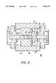
- FIG. 3is an axial sectional view of an exemplary packaged optical isolator including the assembly of FIG. 1.
- FIG. 1illustrates an exemplary (simplified) optical isolator 10 including polarization dispersion and transverse deflection corrective means in accordance with the teachings of the present invention. It is to be understood that in actual operation, such an isolator 10 requires a permanent magnet and may include lensing elements, as discussed hereinbelow in association with FIG. 3. For the sake of clarity, these components are not shown in FIG. 1 and are not considered as necessary for an understanding of the operation of the isolator in accordance with the teachings of the present invention.
- the e-ray emerging from the second birefringent wedge 16will be delayed relative to the o-ray, where the delay (defined as polarization dispersion) may be on the order of a few picoseconds.
- this polarization dispersionis essentially canceled by inserting an additional birefringent device 22 along the optical signal path which functions to adjust the delay between the polarization states such that the e- and- o-rays emerge essentially simultaneously from the isolator 10.
- polarization dispersion correctionis accomplished in this particular embodiment of the present invention by including a birefringent plate 22 of an effective thickness or length L along the optical signal path.
- the plate 22is oriented with respect to the birefringent wedge 16 such that the rays entering the plate 22 exchange polarization states. That is, assuming that, as called for above, the incoming signal propagates from left to right as shown in FIG.
- the plate 22sees the e-ray exiting the second birefringent wedge 16 as an "o" ray, and the o-ray exiting the wedge 16 as an "e" ray.
- the plate 22is shown having its C-axis at an angle of -22.5° with respect to an edge 25 of a front face 24 so as to provide the exchange of polarization state identity.
- the C-axis of the plate 22is rotated a total of 90° so as to be orthogonal to the C-axis of the second wedge 16.
- the C-axis of the plate 22would be oriented at an angle of 90° with respect to the C-axis of the first wedge 14.
- Thisis optically equivalent to having the incoming optical signal propagate through the isolator 10 from right to left, provided that this contemplated propagation direction is taken into consideration in orienting and/or operating the Faraday rotator 10, and especially in choosing the polarity of the applied magnetic field.
- the effective thickness L of plate 22is chosen so that the delay allows the e- and o-rays to exit the isolator 10 simultaneously.
- the plate thickness Lis a function of the refractive indices (i.e., n e and n o ) of the chosen material (e.g. calcite) and is calculated to essentially cancel the polarization dispersion.
- the compensating plate 22extends at an angle ⁇ with respect to a plane normal to a reference axis that forms an extension of an incoming ray R 1 (again adhering to the above convention concerning the incoming ray propagation direction).
- each of such polarized raysencounters a different index of refraction during its passage through the plate 22 than during its passage through the unit 30. This fact is used in accordance with the present invention to achieve the desired restoration of the axial coincidence of such polarized rays on leaving the plate 22 as an output ray R o .
- the tilt angle ⁇is that which will result in a transverse offset ⁇ y with the same sense as if the light were traveling from right to left--i.e. in the opposite direction.
- the unit 30does not contain only the wedges 14 and 16; rather, it also includes the Faraday rotator 12 that is typically separated from the wedges 14 and 16 by respective air gaps.
- the presence of the rotator 12 and/or the air gapshas an influence on the paths of the rays R 1 (o) and R 2 (e) through the isolator unit 10, but this influence may be readily determined or calculated and taken into consideration when choosing the effective thickness L of the plate 22.
- the effective thickness or length Ldoes not exactly correspond to the thickness of the plate 22; rather, L represents the average length of the optical path of the rays R 1 (e) and R 2 (o) through the plate 22, corresponding to the actual thickness of the plate 22 divided by cos ⁇ .
- This differencewhile not negligible, merely constitutes one of the factors,--including the influence of the air gap and the rotator--which are to be taken care of when optimizing the design of the optical isolator assembly 10 during its fabrication and/or assembly.
- the angle ⁇has been determined for several isolator constructions resembling those currently available but with the compensation plate tilt added. Best results have been obtained with an optical isolator structure in which the wedges 14 and 16 had 3.5° crown angles and the aforementioned air gaps were 0.005" in size. In this situation, the tilt angle ⁇ was found to amount to approximately 12.4°. Of course, this is not the only possible, and perhaps not even the most advantageous, implementation; rather, some additional experimentation may still provide further optimization of the isolator design embodying the present invention.
- the main polarization discrimination means implemented by the birefringent wedges 14 and 16, and the auxiliary polarization means comprised of the plate 22,are functionally interchangeable with one another at least insofar as the transverse deflection of polarized light signals is concerned, so that either one could be arranged at the input end and serve for polarizing and splitting the incoming light, while the other would then serve to bring the transversely deflected polarized light signals together.
- the plate 22may be considered to be a transverse offset compensating element that performs actual compensation for the transverse offset ⁇ y when the incoming light travels from left to right, and anticipatory compensation for conditions to be encountered by incoming light propagating from right to left during its passage through the unit 30.
- FIG. 3illustrates an exemplary packaged isolator 40 including a birefringent compensating plate of the present invention.
- the Faraday rotator 12, the first wedge 14 and the second wedge 16are joined (using all optically transparent and anti-reflective material) and disposed within a permanent magnet 42, the magnet 42 being utilized to provide the requisite 45° rotation of polarized light during its passage through the magneto-optic material of the Faraday rotator 12.
- This assemblyis then fixed within an outer package 44.
- An input lensing arrangement 46(again as considered tier the left-to-right incoming light beam propagation direction), used to form a collimated beam, is held within a fixture 48, with the fixture 48 being attached to the outer package 44.
- an output lensing arrangement 50used to form a focused beam, is held within a fixture 52 which is also attached to the outer package 44.
- the polarization dispersion compensation birefringent plate 22 of the present inventionis disposed between the second wedge 16 and the output lensing arrangement 50, extending at an angle ⁇ as shown in FIG. 2.
- the plate 22is held within a fixture 54 that is attached to the outer package 44.
Landscapes
- Physics & Mathematics (AREA)
- Nonlinear Science (AREA)
- General Physics & Mathematics (AREA)
- Optics & Photonics (AREA)
- Engineering & Computer Science (AREA)
- Power Engineering (AREA)
Abstract
Description
Claims (8)
Priority Applications (4)
| Application Number | Priority Date | Filing Date | Title |
|---|---|---|---|
| US08/176,359US5631771A (en) | 1991-09-19 | 1993-12-29 | Optical isolator with polarization dispersion and differential transverse deflection correction |
| EP94309177AEP0661578A3 (en) | 1993-12-29 | 1994-12-09 | Optical isolator with polarization dispersion. |
| JP6336991AJPH07209606A (en) | 1993-12-29 | 1994-12-27 | Optical isolator with polarized-wave dispersion compensation and deflection equalization |
| US08/785,836US5930038A (en) | 1991-09-19 | 1997-01-13 | Optical isolator with polarization dispersion and differential transverse deflection correction |
Applications Claiming Priority (2)
| Application Number | Priority Date | Filing Date | Title |
|---|---|---|---|
| US76266591A | 1991-09-19 | 1991-09-19 | |
| US08/176,359US5631771A (en) | 1991-09-19 | 1993-12-29 | Optical isolator with polarization dispersion and differential transverse deflection correction |
Related Parent Applications (1)
| Application Number | Title | Priority Date | Filing Date |
|---|---|---|---|
| US76266591AContinuation-In-Part | 1991-09-19 | 1991-09-19 |
Related Child Applications (1)
| Application Number | Title | Priority Date | Filing Date |
|---|---|---|---|
| US08/785,836ContinuationUS5930038A (en) | 1991-09-19 | 1997-01-13 | Optical isolator with polarization dispersion and differential transverse deflection correction |
Publications (1)
| Publication Number | Publication Date |
|---|---|
| US5631771Atrue US5631771A (en) | 1997-05-20 |
Family
ID=22644034
Family Applications (2)
| Application Number | Title | Priority Date | Filing Date |
|---|---|---|---|
| US08/176,359Expired - LifetimeUS5631771A (en) | 1991-09-19 | 1993-12-29 | Optical isolator with polarization dispersion and differential transverse deflection correction |
| US08/785,836Expired - LifetimeUS5930038A (en) | 1991-09-19 | 1997-01-13 | Optical isolator with polarization dispersion and differential transverse deflection correction |
Family Applications After (1)
| Application Number | Title | Priority Date | Filing Date |
|---|---|---|---|
| US08/785,836Expired - LifetimeUS5930038A (en) | 1991-09-19 | 1997-01-13 | Optical isolator with polarization dispersion and differential transverse deflection correction |
Country Status (3)
| Country | Link |
|---|---|
| US (2) | US5631771A (en) |
| EP (1) | EP0661578A3 (en) |
| JP (1) | JPH07209606A (en) |
Cited By (27)
| Publication number | Priority date | Publication date | Assignee | Title |
|---|---|---|---|---|
| US5734762A (en)* | 1995-09-15 | 1998-03-31 | Qualop Systems Corporation | Optical isolator system and method |
| US5930038A (en)* | 1991-09-19 | 1999-07-27 | Lucent Technologies Inc. | Optical isolator with polarization dispersion and differential transverse deflection correction |
| US6167174A (en)* | 1998-10-27 | 2000-12-26 | Adc Telecommunications, Inc. | Multiple port, fiber optic isolator |
| US6278547B1 (en)* | 1998-05-06 | 2001-08-21 | Hughes Electronics Corporation | Polarization insensitive faraday attenuator |
| US6331912B1 (en)* | 1997-12-08 | 2001-12-18 | U.S.A. Kaifa Technology, Inc. | Optical circulator |
| US6339492B1 (en)* | 1998-01-23 | 2002-01-15 | Fujitsu Limited | Tunable optical filter |
| US6445499B1 (en)* | 1999-12-31 | 2002-09-03 | Jds Uniphase Corporation | Optical circulators |
| US6553156B1 (en)* | 2000-06-30 | 2003-04-22 | Oplink Communications, Inc. | Optical isolators with ultra-low polarization mode dispersion |
| US6580558B2 (en)* | 2001-04-27 | 2003-06-17 | Hon Hai Precision Ind. Co., Ltd. | Optical isolator |
| EP1164724A3 (en)* | 2000-06-13 | 2004-03-10 | Lucent Technologies Inc. | Polarization mode dispersion compensator for optical fiber communication systems |
| US20040070827A1 (en)* | 2002-10-15 | 2004-04-15 | Wei-Zhong Li | Reflective variable attenuator and tap monitor |
| US7173762B2 (en)* | 2000-10-13 | 2007-02-06 | Finisar Corporation | Optical isolator with reduced insertion loss and minimized polarization mode dispersion |
| US20070110354A1 (en)* | 2005-11-16 | 2007-05-17 | Raydiance, Inc. | Method and apparatus for optical isolation in high power fiber-optic systems |
| US20110069387A1 (en)* | 2009-09-24 | 2011-03-24 | Smm Precision Co., Ltd. | In-line optical isolator |
| US8125704B2 (en) | 2008-08-18 | 2012-02-28 | Raydiance, Inc. | Systems and methods for controlling a pulsed laser by combining laser signals |
| US8135050B1 (en) | 2005-07-19 | 2012-03-13 | Raydiance, Inc. | Automated polarization correction |
| US8139910B2 (en) | 2006-01-23 | 2012-03-20 | Raydiance, Inc. | Systems and methods for control of ultra short pulse amplification |
| US8150271B1 (en) | 2006-03-28 | 2012-04-03 | Raydiance, Inc. | Active tuning of temporal dispersion in an ultrashort pulse laser system |
| US8173929B1 (en) | 2003-08-11 | 2012-05-08 | Raydiance, Inc. | Methods and systems for trimming circuits |
| US8189971B1 (en) | 2006-01-23 | 2012-05-29 | Raydiance, Inc. | Dispersion compensation in a chirped pulse amplification system |
| US8232687B2 (en) | 2006-04-26 | 2012-07-31 | Raydiance, Inc. | Intelligent laser interlock system |
| US8398622B2 (en) | 2003-05-20 | 2013-03-19 | Raydiance, Inc. | Portable optical ablation system |
| US8554037B2 (en) | 2010-09-30 | 2013-10-08 | Raydiance, Inc. | Hybrid waveguide device in powerful laser systems |
| CN103995323A (en)* | 2014-05-13 | 2014-08-20 | 青岛海信宽带多媒体技术有限公司 | Optical module assembly and optical module |
| US8921733B2 (en) | 2003-08-11 | 2014-12-30 | Raydiance, Inc. | Methods and systems for trimming circuits |
| US9022037B2 (en) | 2003-08-11 | 2015-05-05 | Raydiance, Inc. | Laser ablation method and apparatus having a feedback loop and control unit |
| US10969560B2 (en) | 2017-05-04 | 2021-04-06 | Lightpath Technologies, Inc. | Integrated optical assembly and manufacturing the same |
Families Citing this family (16)
| Publication number | Priority date | Publication date | Assignee | Title |
|---|---|---|---|---|
| KR100200210B1 (en)* | 1996-11-30 | 1999-06-15 | 윤종용 | Optical isolator |
| JPH1195054A (en)* | 1997-09-25 | 1999-04-09 | Fujitsu Ltd | Optical device |
| DE19807120A1 (en)* | 1998-02-20 | 1999-08-26 | Zeiss Carl Fa | Optical system with polarization compensator |
| US6421176B1 (en)* | 1998-09-18 | 2002-07-16 | 3M Innovative Properties Company | Optical isolator |
| US6417962B1 (en)* | 1999-07-07 | 2002-07-09 | Corning Incorporated | Optical waveguide amplifier optical service channel accessor device and method of making |
| US6580540B1 (en)* | 2000-06-02 | 2003-06-17 | Northrop Grumman Corporation | Time compensation architectures for controlling timing of optical signals |
| DE60234081D1 (en)* | 2001-02-14 | 2009-12-03 | Finisar Corp | OPTICAL POLARIZATION BEAM SPREADER / COMBINER WITH INSULATION IN THE OPTICAL REVERSE PATH |
| US6654127B2 (en)* | 2001-03-01 | 2003-11-25 | Carl Zeiss Ophthalmic Systems, Inc. | Optical delay line |
| US7301974B2 (en)* | 2001-05-08 | 2007-11-27 | Mitsubishi Denki Kabushiki Kaisha | Wavelength monitoring apparatus |
| US6587273B2 (en)* | 2001-06-25 | 2003-07-01 | Jds Uniphase Corporation | Beam splitting device |
| US6697550B2 (en)* | 2001-10-24 | 2004-02-24 | Renka Corporation | Fast 1×N fiber-optic switch |
| TW505241U (en)* | 2001-12-12 | 2002-10-01 | Hon Hai Prec Ind Co Ltd | Optical fiber isolator |
| JP2003287713A (en)* | 2002-03-27 | 2003-10-10 | Shin Etsu Chem Co Ltd | Optical isolator |
| US7474813B2 (en)* | 2003-11-10 | 2009-01-06 | Finisar Corporation | Connector mountable asymmetric free space optical isolators |
| US8891166B2 (en)* | 2008-08-06 | 2014-11-18 | Seikoh Giken Co., Ltd. | Polarization dependent type optical isolator |
| US8800677B2 (en) | 2012-03-30 | 2014-08-12 | Deere & Company | Aerator hole spacing control with lockout |
Citations (20)
| Publication number | Priority date | Publication date | Assignee | Title |
|---|---|---|---|---|
| US4178073A (en)* | 1977-05-31 | 1979-12-11 | Nippon Electric Co., Ltd. | Optical isolator |
| JPS54159245A (en)* | 1978-06-06 | 1979-12-15 | Mitsubishi Electric Corp | Optical device |
| US4239329A (en)* | 1978-08-04 | 1980-12-16 | Nippon Telegraph And Telephone Public Corporation | Optical nonreciprocal device |
| JPS5816515A (en)* | 1981-07-22 | 1983-01-31 | Top Denshi Kk | Inverter transformer for fluorescent lamp |
| US4548478A (en)* | 1980-12-15 | 1985-10-22 | Fujitsu Limited | Optical device |
| JPS6145219A (en)* | 1984-08-09 | 1986-03-05 | Fujitsu Ltd | optical isolator |
| US4712880A (en)* | 1982-06-28 | 1987-12-15 | Fujitsu Limited | Polarization rotation compensator and optical isolator using the same |
| JPS63139318A (en)* | 1986-12-02 | 1988-06-11 | Fujitsu Ltd | Ld module optical system |
| JPS63244015A (en)* | 1987-03-31 | 1988-10-11 | Nec Corp | Non-polarization type optical isolator |
| JPS63276020A (en)* | 1987-05-08 | 1988-11-14 | Fujitsu Ltd | Polarization preserving optical isolator |
| JPH0283523A (en)* | 1988-09-20 | 1990-03-23 | Nec Corp | Optical isolator |
| JPH02188715A (en)* | 1989-01-18 | 1990-07-24 | Nec Corp | Optical isolator |
| WO1991014193A1 (en)* | 1990-03-14 | 1991-09-19 | Toyo Communication Equipment Co., Ltd. | Optical isolator |
| US5052786A (en)* | 1990-03-05 | 1991-10-01 | Massachusetts Institute Of Technology | Broadband faraday isolator |
| US5151955A (en)* | 1990-06-20 | 1992-09-29 | Kabushiki Kaisha Shinkosha | Optical isolator |
| US5237445A (en)* | 1990-11-30 | 1993-08-17 | Shimadzu Corporation | Optical isolator |
| US5251058A (en)* | 1989-10-13 | 1993-10-05 | Xerox Corporation | Multiple beam exposure control |
| US5278853A (en)* | 1991-05-28 | 1994-01-11 | Mitsubishi Gas Chemical Co., Ltd. | Optical isolator |
| US5315431A (en)* | 1992-04-20 | 1994-05-24 | Fuji Electrochemical Co., Ltd. | Optical isolator |
| US5446578A (en)* | 1988-07-21 | 1995-08-29 | Hewlett-Packard Company | Polarization preserving optical isolator |
Family Cites Families (7)
| Publication number | Priority date | Publication date | Assignee | Title |
|---|---|---|---|---|
| JPH02126219A (en)* | 1988-11-04 | 1990-05-15 | Fuji Elelctrochem Co Ltd | Optical isolator |
| JPH0561000A (en)* | 1991-08-31 | 1993-03-12 | Namiki Precision Jewel Co Ltd | Optical isolator |
| US5631771A (en)* | 1991-09-19 | 1997-05-20 | Lucent Technologies Inc. | Optical isolator with polarization dispersion and differential transverse deflection correction |
| EP0533398A1 (en)* | 1991-09-19 | 1993-03-24 | AT&T Corp. | Optical isolator with polarization dispersion correction |
| US5276747A (en)* | 1993-01-21 | 1994-01-04 | E-Tek Dynamics, Inc. | Polarization-independent optical switch/attenuator |
| JPH08505961A (en)* | 1993-01-21 | 1996-06-25 | イー−テック・ダイナミックス・インコーポレイテッド | Optical device with low polarization mode dispersion |
| US5602673A (en)* | 1993-12-29 | 1997-02-11 | Lucent Technologies Inc. | Optical isolator without polarization mode dispersion |
- 1993
- 1993-12-29USUS08/176,359patent/US5631771A/ennot_activeExpired - Lifetime
- 1994
- 1994-12-09EPEP94309177Apatent/EP0661578A3/ennot_activeWithdrawn
- 1994-12-27JPJP6336991Apatent/JPH07209606A/enactivePending
- 1997
- 1997-01-13USUS08/785,836patent/US5930038A/ennot_activeExpired - Lifetime
Patent Citations (20)
| Publication number | Priority date | Publication date | Assignee | Title |
|---|---|---|---|---|
| US4178073A (en)* | 1977-05-31 | 1979-12-11 | Nippon Electric Co., Ltd. | Optical isolator |
| JPS54159245A (en)* | 1978-06-06 | 1979-12-15 | Mitsubishi Electric Corp | Optical device |
| US4239329A (en)* | 1978-08-04 | 1980-12-16 | Nippon Telegraph And Telephone Public Corporation | Optical nonreciprocal device |
| US4548478A (en)* | 1980-12-15 | 1985-10-22 | Fujitsu Limited | Optical device |
| JPS5816515A (en)* | 1981-07-22 | 1983-01-31 | Top Denshi Kk | Inverter transformer for fluorescent lamp |
| US4712880A (en)* | 1982-06-28 | 1987-12-15 | Fujitsu Limited | Polarization rotation compensator and optical isolator using the same |
| JPS6145219A (en)* | 1984-08-09 | 1986-03-05 | Fujitsu Ltd | optical isolator |
| JPS63139318A (en)* | 1986-12-02 | 1988-06-11 | Fujitsu Ltd | Ld module optical system |
| JPS63244015A (en)* | 1987-03-31 | 1988-10-11 | Nec Corp | Non-polarization type optical isolator |
| JPS63276020A (en)* | 1987-05-08 | 1988-11-14 | Fujitsu Ltd | Polarization preserving optical isolator |
| US5446578A (en)* | 1988-07-21 | 1995-08-29 | Hewlett-Packard Company | Polarization preserving optical isolator |
| JPH0283523A (en)* | 1988-09-20 | 1990-03-23 | Nec Corp | Optical isolator |
| JPH02188715A (en)* | 1989-01-18 | 1990-07-24 | Nec Corp | Optical isolator |
| US5251058A (en)* | 1989-10-13 | 1993-10-05 | Xerox Corporation | Multiple beam exposure control |
| US5052786A (en)* | 1990-03-05 | 1991-10-01 | Massachusetts Institute Of Technology | Broadband faraday isolator |
| WO1991014193A1 (en)* | 1990-03-14 | 1991-09-19 | Toyo Communication Equipment Co., Ltd. | Optical isolator |
| US5151955A (en)* | 1990-06-20 | 1992-09-29 | Kabushiki Kaisha Shinkosha | Optical isolator |
| US5237445A (en)* | 1990-11-30 | 1993-08-17 | Shimadzu Corporation | Optical isolator |
| US5278853A (en)* | 1991-05-28 | 1994-01-11 | Mitsubishi Gas Chemical Co., Ltd. | Optical isolator |
| US5315431A (en)* | 1992-04-20 | 1994-05-24 | Fuji Electrochemical Co., Ltd. | Optical isolator |
Cited By (35)
| Publication number | Priority date | Publication date | Assignee | Title |
|---|---|---|---|---|
| US5930038A (en)* | 1991-09-19 | 1999-07-27 | Lucent Technologies Inc. | Optical isolator with polarization dispersion and differential transverse deflection correction |
| US5734762A (en)* | 1995-09-15 | 1998-03-31 | Qualop Systems Corporation | Optical isolator system and method |
| US6331912B1 (en)* | 1997-12-08 | 2001-12-18 | U.S.A. Kaifa Technology, Inc. | Optical circulator |
| US6339492B1 (en)* | 1998-01-23 | 2002-01-15 | Fujitsu Limited | Tunable optical filter |
| US6278547B1 (en)* | 1998-05-06 | 2001-08-21 | Hughes Electronics Corporation | Polarization insensitive faraday attenuator |
| US6167174A (en)* | 1998-10-27 | 2000-12-26 | Adc Telecommunications, Inc. | Multiple port, fiber optic isolator |
| US6445499B1 (en)* | 1999-12-31 | 2002-09-03 | Jds Uniphase Corporation | Optical circulators |
| EP1164724A3 (en)* | 2000-06-13 | 2004-03-10 | Lucent Technologies Inc. | Polarization mode dispersion compensator for optical fiber communication systems |
| US6801721B1 (en) | 2000-06-13 | 2004-10-05 | Lucent Technologies Inc. | Polarization mode dispersion compensator for optical fiber communication systems |
| US6553156B1 (en)* | 2000-06-30 | 2003-04-22 | Oplink Communications, Inc. | Optical isolators with ultra-low polarization mode dispersion |
| US7173762B2 (en)* | 2000-10-13 | 2007-02-06 | Finisar Corporation | Optical isolator with reduced insertion loss and minimized polarization mode dispersion |
| US6580558B2 (en)* | 2001-04-27 | 2003-06-17 | Hon Hai Precision Ind. Co., Ltd. | Optical isolator |
| US20040070827A1 (en)* | 2002-10-15 | 2004-04-15 | Wei-Zhong Li | Reflective variable attenuator and tap monitor |
| US6839170B2 (en)* | 2002-10-15 | 2005-01-04 | Oplink Communications, Inc. | Optical isolator |
| US8398622B2 (en) | 2003-05-20 | 2013-03-19 | Raydiance, Inc. | Portable optical ablation system |
| US8173929B1 (en) | 2003-08-11 | 2012-05-08 | Raydiance, Inc. | Methods and systems for trimming circuits |
| US8921733B2 (en) | 2003-08-11 | 2014-12-30 | Raydiance, Inc. | Methods and systems for trimming circuits |
| US9022037B2 (en) | 2003-08-11 | 2015-05-05 | Raydiance, Inc. | Laser ablation method and apparatus having a feedback loop and control unit |
| US8135050B1 (en) | 2005-07-19 | 2012-03-13 | Raydiance, Inc. | Automated polarization correction |
| US7433558B2 (en)* | 2005-11-16 | 2008-10-07 | Raydiance, Inc | Methods for optical isolation in high power fiber-optic systems |
| US20080063340A1 (en)* | 2005-11-16 | 2008-03-13 | Raydiance, Inc. | Methods for optical isolation in high power fiber-optic systems |
| US7308171B2 (en)* | 2005-11-16 | 2007-12-11 | Raydiance, Inc. | Method and apparatus for optical isolation in high power fiber-optic systems |
| US20070110354A1 (en)* | 2005-11-16 | 2007-05-17 | Raydiance, Inc. | Method and apparatus for optical isolation in high power fiber-optic systems |
| US8139910B2 (en) | 2006-01-23 | 2012-03-20 | Raydiance, Inc. | Systems and methods for control of ultra short pulse amplification |
| US8189971B1 (en) | 2006-01-23 | 2012-05-29 | Raydiance, Inc. | Dispersion compensation in a chirped pulse amplification system |
| US8150271B1 (en) | 2006-03-28 | 2012-04-03 | Raydiance, Inc. | Active tuning of temporal dispersion in an ultrashort pulse laser system |
| US9281653B2 (en) | 2006-04-26 | 2016-03-08 | Coherent, Inc. | Intelligent laser interlock system |
| US8232687B2 (en) | 2006-04-26 | 2012-07-31 | Raydiance, Inc. | Intelligent laser interlock system |
| US8125704B2 (en) | 2008-08-18 | 2012-02-28 | Raydiance, Inc. | Systems and methods for controlling a pulsed laser by combining laser signals |
| US8115998B2 (en)* | 2009-09-24 | 2012-02-14 | Smm Precision Co., Ltd. | In-line optical isolator |
| US20110069387A1 (en)* | 2009-09-24 | 2011-03-24 | Smm Precision Co., Ltd. | In-line optical isolator |
| US8554037B2 (en) | 2010-09-30 | 2013-10-08 | Raydiance, Inc. | Hybrid waveguide device in powerful laser systems |
| CN103995323A (en)* | 2014-05-13 | 2014-08-20 | 青岛海信宽带多媒体技术有限公司 | Optical module assembly and optical module |
| CN103995323B (en)* | 2014-05-13 | 2015-11-25 | 青岛海信宽带多媒体技术有限公司 | A kind of optical module assembly and optical module |
| US10969560B2 (en) | 2017-05-04 | 2021-04-06 | Lightpath Technologies, Inc. | Integrated optical assembly and manufacturing the same |
Also Published As
| Publication number | Publication date |
|---|---|
| EP0661578A3 (en) | 1996-10-30 |
| EP0661578A2 (en) | 1995-07-05 |
| JPH07209606A (en) | 1995-08-11 |
| US5930038A (en) | 1999-07-27 |
Similar Documents
| Publication | Publication Date | Title |
|---|---|---|
| US5631771A (en) | Optical isolator with polarization dispersion and differential transverse deflection correction | |
| US5446578A (en) | Polarization preserving optical isolator | |
| US6480331B1 (en) | Reflection-type polarization-independent optical isolator, optical isolator/amplifier/monitor, and optical system | |
| JP2757093B2 (en) | Non-polarization dispersion type optical isolator | |
| EP0661579B1 (en) | Optical isolator without polarization mode dispersion | |
| US5682446A (en) | Polarization mode dispersion-free circulator | |
| US7081996B2 (en) | Isolated polarization beam splitter and combiner | |
| EP1176451A2 (en) | Isolated polarization beam splitter and combiner | |
| JPH0954283A (en) | Polarization independent type optical isolator device | |
| CA2344021C (en) | Polarization beam splitter or combiner | |
| EP0533398A1 (en) | Optical isolator with polarization dispersion correction | |
| US5066092A (en) | Optical arrangement for a feedback-free coupling of a laser emission emitted by a semiconductor laser into an optical fiber | |
| US7173762B2 (en) | Optical isolator with reduced insertion loss and minimized polarization mode dispersion | |
| US20030053209A1 (en) | Dual stage optical isolator with reduced polarization mode dispersion and beam offset | |
| JPH07191280A (en) | Optical isolator | |
| US11719965B2 (en) | Optical isolators | |
| US6449091B1 (en) | Optical isolator | |
| JP2930431B2 (en) | Polarization-independent optical isolator | |
| JPH0477713A (en) | Optical isolator independent of polarization | |
| JP3716981B2 (en) | Optical isolator | |
| JPH07191279A (en) | Optical isolator | |
| JPH04102821A (en) | Polarization nondependent type optical isolator | |
| JPH0454929B2 (en) | ||
| JP2989983B2 (en) | Optical isolator | |
| JPH0634916A (en) | Optical isolator |
Legal Events
| Date | Code | Title | Description |
|---|---|---|---|
| AS | Assignment | Owner name:AMERICAN TELEPHONE AND TELEGRAPH COMPANY, NEW YORK Free format text:ASSIGNMENT OF ASSIGNORS INTEREST;ASSIGNOR:SWAN, CLARENCE BURKE;REEL/FRAME:006877/0609 Effective date:19940225 | |
| AS | Assignment | Owner name:LUCENT TECHNOLOGIES INC., NEW JERSEY Free format text:ASSIGNMENT OF ASSIGNORS INTEREST;ASSIGNOR:AT&T CORP.;REEL/FRAME:008684/0001 Effective date:19960329 | |
| STCF | Information on status: patent grant | Free format text:PATENTED CASE | |
| FEPP | Fee payment procedure | Free format text:PAYOR NUMBER ASSIGNED (ORIGINAL EVENT CODE: ASPN); ENTITY STATUS OF PATENT OWNER: LARGE ENTITY | |
| FPAY | Fee payment | Year of fee payment:4 | |
| FEPP | Fee payment procedure | Free format text:PAYER NUMBER DE-ASSIGNED (ORIGINAL EVENT CODE: RMPN); ENTITY STATUS OF PATENT OWNER: LARGE ENTITY Free format text:PAYOR NUMBER ASSIGNED (ORIGINAL EVENT CODE: ASPN); ENTITY STATUS OF PATENT OWNER: LARGE ENTITY | |
| FPAY | Fee payment | Year of fee payment:8 | |
| FPAY | Fee payment | Year of fee payment:12 | |
| AS | Assignment | Owner name:AGERE SYSTEMS INC., PENNSYLVANIA Free format text:ASSIGNMENT OF ASSIGNORS INTEREST;ASSIGNOR:LUCENT TECHNOLOGIES INC.;REEL/FRAME:024697/0450 Effective date:20020531 | |
| AS | Assignment | Owner name:DEUTSCHE BANK AG NEW YORK BRANCH, AS COLLATERAL AG Free format text:PATENT SECURITY AGREEMENT;ASSIGNORS:LSI CORPORATION;AGERE SYSTEMS LLC;REEL/FRAME:032856/0031 Effective date:20140506 | |
| AS | Assignment | Owner name:LSI CORPORATION, CALIFORNIA Free format text:TERMINATION AND RELEASE OF SECURITY INTEREST IN PATENT RIGHTS (RELEASES RF 032856-0031);ASSIGNOR:DEUTSCHE BANK AG NEW YORK BRANCH, AS COLLATERAL AGENT;REEL/FRAME:037684/0039 Effective date:20160201 Owner name:AGERE SYSTEMS LLC, PENNSYLVANIA Free format text:TERMINATION AND RELEASE OF SECURITY INTEREST IN PATENT RIGHTS (RELEASES RF 032856-0031);ASSIGNOR:DEUTSCHE BANK AG NEW YORK BRANCH, AS COLLATERAL AGENT;REEL/FRAME:037684/0039 Effective date:20160201 |