US5631685A - Apparatus and method for drying ink deposited by ink jet printing - Google Patents
Apparatus and method for drying ink deposited by ink jet printingDownload PDFInfo
- Publication number
- US5631685A US5631685AUS08/159,908US15990893AUS5631685AUS 5631685 AUS5631685 AUS 5631685AUS 15990893 AUS15990893 AUS 15990893AUS 5631685 AUS5631685 AUS 5631685A
- Authority
- US
- United States
- Prior art keywords
- ink
- paper
- microwave
- cut sheet
- applying
- Prior art date
- Legal status (The legal status is an assumption and is not a legal conclusion. Google has not performed a legal analysis and makes no representation as to the accuracy of the status listed.)
- Expired - Lifetime
Links
Images


Classifications
- H—ELECTRICITY
- H05—ELECTRIC TECHNIQUES NOT OTHERWISE PROVIDED FOR
- H05B—ELECTRIC HEATING; ELECTRIC LIGHT SOURCES NOT OTHERWISE PROVIDED FOR; CIRCUIT ARRANGEMENTS FOR ELECTRIC LIGHT SOURCES, IN GENERAL
- H05B6/00—Heating by electric, magnetic or electromagnetic fields
- H05B6/64—Heating using microwaves
- H05B6/78—Arrangements for continuous movement of material
- B—PERFORMING OPERATIONS; TRANSPORTING
- B41—PRINTING; LINING MACHINES; TYPEWRITERS; STAMPS
- B41J—TYPEWRITERS; SELECTIVE PRINTING MECHANISMS, i.e. MECHANISMS PRINTING OTHERWISE THAN FROM A FORME; CORRECTION OF TYPOGRAPHICAL ERRORS
- B41J11/00—Devices or arrangements of selective printing mechanisms, e.g. ink-jet printers or thermal printers, for supporting or handling copy material in sheet or web form
- B41J11/0015—Devices or arrangements of selective printing mechanisms, e.g. ink-jet printers or thermal printers, for supporting or handling copy material in sheet or web form for treating before, during or after printing or for uniform coating or laminating the copy material before or after printing
- B41J11/002—Curing or drying the ink on the copy materials, e.g. by heating or irradiating
- B41J11/0021—Curing or drying the ink on the copy materials, e.g. by heating or irradiating using irradiation
- B41J11/00216—Curing or drying the ink on the copy materials, e.g. by heating or irradiating using irradiation using infrared [IR] radiation or microwaves
- H—ELECTRICITY
- H05—ELECTRIC TECHNIQUES NOT OTHERWISE PROVIDED FOR
- H05B—ELECTRIC HEATING; ELECTRIC LIGHT SOURCES NOT OTHERWISE PROVIDED FOR; CIRCUIT ARRANGEMENTS FOR ELECTRIC LIGHT SOURCES, IN GENERAL
- H05B6/00—Heating by electric, magnetic or electromagnetic fields
- H05B6/64—Heating using microwaves
- H05B6/70—Feed lines
- H05B6/705—Feed lines using microwave tuning
- H—ELECTRICITY
- H05—ELECTRIC TECHNIQUES NOT OTHERWISE PROVIDED FOR
- H05B—ELECTRIC HEATING; ELECTRIC LIGHT SOURCES NOT OTHERWISE PROVIDED FOR; CIRCUIT ARRANGEMENTS FOR ELECTRIC LIGHT SOURCES, IN GENERAL
- H05B6/00—Heating by electric, magnetic or electromagnetic fields
- H05B6/64—Heating using microwaves
- H05B6/76—Prevention of microwave leakage, e.g. door sealings
- H—ELECTRICITY
- H05—ELECTRIC TECHNIQUES NOT OTHERWISE PROVIDED FOR
- H05B—ELECTRIC HEATING; ELECTRIC LIGHT SOURCES NOT OTHERWISE PROVIDED FOR; CIRCUIT ARRANGEMENTS FOR ELECTRIC LIGHT SOURCES, IN GENERAL
- H05B2206/00—Aspects relating to heating by electric, magnetic, or electromagnetic fields covered by group H05B6/00
- H05B2206/04—Heating using microwaves
- H05B2206/046—Microwave drying of wood, ink, food, ceramic, sintering of ceramic, clothes, hair
Definitions
- the present inventionrelates generally to drying ink deposited by an ink jet printer and more particularly relates to an apparatus and method for controlling paper deformation due to ink jet printing by the use of microwave energy.
- thermal ink jet inksinclude a colorant and a liquid which is typically an aqueous liquid vehicle.
- Some thermal ink jet inksalso include a low vapor pressure solvent.
- the inkis deposited on the substrate to form an image in the form of text and/or graphics. Once deposited, the liquid is removed from the ink and paper to fix the ink to the substrate.
- the amount of liquid to be removedvaries with the amount of ink deposited on the substrate. If a sheet is covered with 10% printing, as in text only printing, the amount of liquid to be removed is quite small. If the sheet is covered with 90% printing, however, as when a graphic image is printed, the amount of liquid to be removed is substantially more and can cause image defects and paper deformation if not removed very rapidly.
- Liquidcan be removed from the ink and printed substrate by a number of methods.
- One simple methodis natural air drying in which the liquid component of the ink deposited on the substrate is allowed to evaporate without mechanical assistance resulting in natural drying.
- Another methodis to send the printed substrate through a dryer to evaporate the liquid.
- a special paperis used in which the liquid is absorbed by a thin coating of absorptive material deposited on the surface of the paper. Blotting of the printed substrate is also known.
- Ink compositionsalso have an effect on the drying rates and drying efficiency. For example, highly absorptive (fast drying) inks while requiring less ink to be removed by a dryer are prone to image quality defects such as feathering, raggedness, and strike through. On the other hand, slightly absorbtive inks require more power from a dryer to dry since more ink requires evaporation.
- the rate at which the image is driedis also critical for controlling the print quality.
- a slow drying ratecan achieve ink permanence or drying effectiveness but also can result in image quality defects such as excessive image feathering or strike through. Additionally, a slow drying rate can result in image offset (ink from one sheet of paper is transferred to another sheet of paper because the ink has not dried completely), smear and spreading from contact with exit rolls, baffles and output stacking of the individual sheets.
- a very fast drying ratecan result in image mottle and image spatter.
- Drying ratesare particularly critical when substrates are printed at high rates of speeds. Not only must image deformations and paper deformations be controlled, but the drying times must be short due to the high printing rates to ensure no offset at exit rolls.
- a dryermust achieve image fixing (no offset/smear) and good image quality to reduce or prevent image disturbance, distortion, feathering and strike through.
- the dryermust preferably reduce or eliminate cockle and curl.
- many dryersproduce uneven drying rates resulting in uneven drying patterns.
- infrared drying techniqueshave been adopted. This method can, however, cause browning of paper during paper jams due to the elevated temperatures produced by the infrared heat.
- U.S. Pat. No. 3,617,953 to Kingma et al.describes a microwave impedance matching system for matching a microwave input waveguide to a microwave output waveguide.
- a first and second electromechanical phase shifterare moved transversely in waveguide sections to produce varying amount of differential phase shift.
- U.S. Pat. No. 3,672,066 to Stephansendiscloses a microwave drying apparatus which includes a serpentine waveguide
- the deviceincludes two opposed air cushions which force a web of material passing through the device to stay midway between the opposite waveguides.
- U.S. Pat. No. 3,739,130 to Whitediscloses a multicavity microwave applicator for uniformly treating a moving web of material with microwave energy.
- the applicatoris formed of two separate sets of cavity resonators which are intermeshed with one another so that the resonators of one set are alternated with the resonators of the second set in a side-by-side relationship.
- U.S. Pat. No. 3,783,414 to Klein et al.describes a termination for a transmission line or waveguide of small weight and size capable of absorbing high levels of power and capable of achieving a VSWR in the order of 1.05 to 1.20 over 10-20 percent frequency bands.
- U.S. Pat. No. 4,234,775 to Wolfberg et al.discloses a device which has a serpentine waveguide and uses microwave energy to remove moisture from a moving web.
- the microwave energytakes the form of standing waves which are purposefully disrupted to cause the peaks of the standing waves to continuously oscillate along the various sections of the waveguide, resulting in a more uniform application of the microwave energy across the width the web.
- U.S. Pat. No. 4,286,135 to Green et al.describes a waveguide isolator having microwave ferrite bars to reduce energy reflected into the microwave source.
- a blower fandraws air past the microwave source and through a waveguide to provide cooling.
- U.S. Pat. No. 4,352,691 to Owatari et al.describes liquid ink compositions including a water-soluble dye, an alkali material, at least one wetting agent and water suited for ink jet type printers. Ink drying time is about five seconds.
- U.S. Pat. No. 4,469,026 to Irwindescribes a method and apparatus for drying ink printed on print media. Drying is controlled according to print parameters such as print data density, characteristics of the ink, and ambient humidity.
- the dryermay be a conventional hot roll, a hot platen, a lamp or a microwave dryer.
- U.S. Pat. No. 4,482,239 to Hosono et al.describes an electrophotographic copying machine which visualizes electrostatic latent images with developer fixed by microwave radiation.
- the developeris a colored developing powder composed of thermoplastic resin having a high dielectric constant and magnetic powder having magnetic loss.
- U.S. Pat. No. 4,754,238 to Schuller et al.describes a microwave absorber including a hollow body consisting of microwave-absorbing material which is arranged in a housing. At least one inlet and one outlet are provided for a gaseous cooling fluid which streams through the container to carry away heat produced by microwave energy which has been absorbed by the absorbing body.
- U.S. Pat. No. 4,970,528 to Beaufort et al.describes a method for uniformly drying ink on paper from an ink jet printer. While paper is transferred from an input paper supply tray to an output paper collection tray, the paper receives the uniform heat flux from an infrared bulb which is located on the axis of symmetry for the paper transport path. The per page processing speed for this apparatus was increased from 2 minutes per page using no dryer at all, to 13 seconds per page using the described uniform dryer.
- U.S. Pat. No. 5,079,507 to Ishida et al.describes an automatic impedance adjusting apparatus for adjusting an impedance seen looking toward a microwave load.
- a cooling air outletexhausts cooling air into a circular waveguide.
- U.S. Pat. No. 5,207,824 to Moffatt et al.describes ink formulations for control of paper cockle in thermal ink jet printing.
- the inkcontains the components of water, dye, and a low vapor pressure solvent, which contains an organic compound or anti-cockle agent.
- U.S. Pat. No. 5,214,442 to Rollerdescribes an adaptive dryer to minimize heating power requirements of a printer by determining mass-area coverage of ink on a page prior to drying.
- U.S. Pat. No. 5,220,346 to Carreira et al.describes a printing process using an ink composition comprising an aqueous liquid vehicle, a colorant and an ionic compound at least partially ionizable in the liquid vehicle applied to a substrate in an imagewise fashion and subsequently exposed to microwave radiation to dry the images on the substrate.
- the apparatuscomprises a plurality of waveguide sections provided with slots in the sides thereof through which a sheet of material can be passed for drying.
- the waveguide sectionsare arranged in a serpentine manner.
- a microwave sourceis attached to one end of the waveguide and a load is attached to the other end of the waveguide.
- Japanese Laid Open Publication 107,490 to Yamaguishidescribes an apparatus to dry ink printed out by means of an ink jet printer by utilizing a microwave.
- European Patent Application Publication No. 538 071-A2 to Yasuhiko et al.describes an ink jet recording apparatus having a low temperature heater and a high temperature heater to dry the ink.
- the low temperature heaterheats the recording sheet and the high temperature heater heats the ink recorded on the recording sheet to a temperature at which the ink is dried and fixed.
- an apparatus for drying ink deposited on a cut sheet of paperincludes a microwave generating member, an applying member to apply microwave power to the paper, and a transport member for transporting the paper through the applying member.
- a method for drying ink deposited on a cut sheet of paperby applying microwave power using a microwave dryer generating resonating traveling waves to the deposited ink within about five seconds or less after depositing the ink on the paper and removing excess liquid from the deposited ink through continued application of the microwave power.
- the short time period between printing and dryingis essential for paper deformation control.
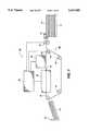
- FIG. 1is a schematic view of an ink jet printer suitable for use with the present invention
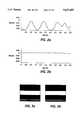
- FIG. 2ais a graph of the cockle profile of a non-microwave dried image
- FIG. 2bis a graph of the cockle profile of a microwave dried image in accordance with the present invention.
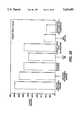
- FIG. 2cis a bar graph showing the final steady state cockle for various drying modes
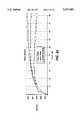
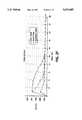
- FIG. 2dis a graph showing cockle reduction as a function of increasing microwave drying rate
- FIG. 2eis a graph showing the amount of cockle versus time with no active drying by allowing ambient drying
- FIG. 2fis a graph showing the amount of cockle versus time with active drying by contacting the sheet on a heated platen
- FIG. 3ais a sample panel of a tri-color non-microwave dried image with intercolor bleed
- FIG. 3ba sample panel of a tri-color microwave dried image in accordance with the present invention
- FIG. 4ais a bar graph illustrating hanging radius curl for both ambient (natural) and microwave dried images
- FIG. 4bshows the hanging radius curl state with and without microwave drying
- FIG. 5is a bar graph illustrating surface and show through optical densities for ambient and microwave dried images
- FIG. 6is a perspective view of a microwave dryer in accordance with the present invention.
- FIG. 7is an elevational view of the FIG. 6 microwave dryer
- FIG. 8is a sectional plan view of a three-branch coupler
- FIG. 9is a sectional view of a three-branch coupler and an eight pass serpentine applicator in accordance with the present invention.
- FIG. 10is a plan view of a paper entrance slot
- FIG. 11is a sectional plan view of a U-shaped connecting member of the serpentine applicator
- FIG. 12is a graph showing a reduction in standing wave ratios with respect to the cut distance of the U-shaped connecting member
- FIG. 13is a perspective view of a microwave dryer and a manifold of the present invention.
- FIG. 14is a plan view of the serpentine applicator defining holes for the application of convective hot air for drying.
- FIG. 1illustrates a schematic view of an ink jet printer 10 of the present invention.
- the ink jet printer 10includes an input tray 12 containing cut sheets 14 of paper stock to be printed upon by the ink jet printer 10. Single sheets 14 of paper are removed from the input tray 12 by a pick-up roller 16 and fed by feed rollers 18 to a paper transport mechanism 20.
- the paper transport mechanism 20moves the sheet 14 by a feed belt or belts 22 driven by rollers 24 beneath a printing member 26.
- the belts 22are made of a material transparent to microwave power having a low dielectric constant.
- the printing member 26includes a pagewidth ink jet printhead which deposits ink on the sheet 14 as the sheet moves past the printhead.
- the pagewidth ink jet printheadis a linear array of print nozzles as wide as the sheet so that ink is deposited across the entire width of a sheet.
- the present inventionis equally applicable, however, to printers having an ink jet printhead which moves across the sheet 14 periodically, in swaths, to form the image, much like a typewriter.
- the print member 26includes an ink supply and the necessary electronics to control the deposition of ink on the page.
- ink specially formulated to be heated by microwave poweris used.
- Such inkmay include compounds designed to couple with the microwave power for increasing the amount of heat conducted thereby.
- One such compoundis an ionic compound at least partially ionizable in the liquid vehicle.
- the sheet 14is carried by the paper transport, immediately after printing or within about 5 seconds or less, to a microwave dryer 28.
- the sheetenters an input slot 30 and exits an output slot 32.
- a transport mechanismsuch as one using a vacuum applied to the bottom side of the paper or one using a static mat carries the paper through the microwave dryer 28.
- microwave poweris delivered to the sheet 14 to thereby dry the ink deposited thereon.
- the sheetis sent to an output tray 34.
- a controller 36controls the printing member 26, the microwave dryer 28, and the paper transport mechanism 20 as would be understood by one skilled in the art.
- an adaptive dryer control for ink jet processorscan also be used.
- Microwave dryer 28has such a fast drying rate that the excess liquid in the ink on the substrate is evaporated from the surface of the printed sheet before any appreciable absorption occurs. Additionally, microwave power generated in the dryer 28 produces an electric field sufficiently large to effectively dry a thin layer of ink on the paper substrate.
- inkis deposited on the substrate from printhead 26, and the printed substrate is passed to dryer 28 for rapid drying.
- the substratetravels through dryer 28 at a speed ranging from about 2 inches to 20 inches per second, or from about 10 prints to 200 prints per minute.
- input slot 30is located approximately three inches from printhead 26. With the paper speed of 2 to 20 inches per second, the total time from depositing the ink on the substrate to entering the dryer is approximately 1.5 seconds to 0.15 seconds.
- a serpentine dryerfor example, with a total drying zone of 6.75 inches, the substrate exits the dryer in 5 to 0.5 seconds.
- FIG. 2ais a graph of the cockle profile for non-microwave dried ink.
- FIG. 2bshows the cockle profile of microwave dried ink.
- the microwave dried inkhas a generally flat profile, whereas the non-microwave dried ink has an uneven, choppy profile.
- microwave dried inkdoes not show through the back of the substrate or paper as opposed to non-microwave dried ink which has a tendency to show through the other side.
- FIG. 2cshows average cockle magnitudes for various drying modes and for Xerographic copying.
- the bars for each categoryrepresent average heights of cockle in inches.
- the sample paper used for this experimentwas Xerox 4024 20# Champion Courtland. It can be seen from this graph that microwave dried images have significantly reduced cockle, close to the cockle of an image produced by Xerographic copying. It is preferable to keep cockle height below 15 mil.
- FIG. 2dshows the way in which the average cockle magnitude decreases with increasing magnetron output power.
- the magnetron powerincreases, the cockle magnitude decreases, approaching cockle of virgin paper run through a microwave dryer having no image. Also, as the heating rate increases, drying time is reduced and cockle growth is suppressed.
- Courtland 4200 paper 5.2% MCfull tone, 1.8 mg/cm 2 ink density was used, and the conditions for the test were 73° F. ambient and 65% relative humidity.
- the paperhad a 5 inches per second (IPS) travel rate, and time between printing and exit of dryer was 4 seconds.
- IPSinches per second
- FIG. 2eis a graph showing the amount of cockle or cockle height versus time with no active drying for full tone (1.6 mg/cm 2 ), half tone (0.8 mg/cm 2 ) and quarter tone (0.4 mg/cm 2 ) printing of carbon black ink, with 0.25 inches of H 2 O hold down of the sheet.
- cockle height shown in inchesincreases rapidly until approximately 3 seconds at which time cockle height begins to gradually level off. If cockle height is to be controlled or suppressed drying must be applied within about 3 to 5 seconds after printing.
- FIG. 2fis a graph showing the amount of cockle versus time with active drying using a 100° C. platen for test purposes. Again, measurements were made for full tone, half tone and quarter tone printing of carbon black ink with 2" of H 2 O holdown.
- FIG. 2eshows that if a full tone printed sheet is dried in less than 5 seconds, cockle height can be effectively suppressed. In this example, the image is dried in about 5 seconds, and the cockle is suppressed when compared to FIG. 2e. After 5 seconds, the curve for full tone drops off rapidly, indicating the paper equilibrates to a lower cockle height once dry. With a faster heating rate as in the case of microwave drying, cockle is suppressed much more rapidly.
- FIGS. 3a and 3billustrate bleeding between colors.
- FIG. 3ashows an ambient dried tri-color panel of ink in which the outer two darker colors have bled into the lighter interior panel.
- FIG. 3bshows a microwave dried tri-color panel in which the colors have not bled together at their interface.
- image qualityis greatly enhanced by rapid drying. It is important to deliver the printed sheet to the microwave dryer before significant bleed occurs. The application of microwave power will then stop any additional bleed.
- microwave heatingis very effective in halting and controlling image quality defects immediately after exposure since the internal heating of absorbed ink insures that all the moisture is driven out by evaporation.
- FIG. 4ashows the output curl magnitudes for various area coverage for both ambient (natural air drying) and microwave drying measured at the output slot 32.
- the hanging radius curlcharacterizes the flatness of the sheet, i.e., the greater the hanging radius curl, the flatter the sheet.
- Very flat paperhas a hanging radius of greater than 20 inches but paper having a hanging radius of greater than 10 inches is acceptable for paper handling (Duplex Feeder).
- the microwave dried sheethas a greater hanging radius curl.
- the paper used in these testswas 4024 20# Champion Courtland run at 5 IPS on the test fixture with an initial MC equal to 4.9%, and the ink used was the ink disclosed in co-pending U.S. Pat. No. 5,220,346.
- FIG. 4bshows the hanging radius curl state before and after microwave drying for virgin paper, printed paper, microwave dried virgin paper and microwave dried printed paper of Champion/Courtland 20# paper having ambient moisture content.
- hanging radius curlis considered to be acceptable if the curl exceeds approximately 12 inches in either direction.
- Tlindicates that the curl is towards the image and Al indicates the curl is away from the image.
- line 1the paper, after printing with 100% area coverage and exiting the printing zone, approaches in the direction of the arrow, unacceptable levels of hanging radius curl.
- the sheetnow enters the microwave dryer just after printing with ink, shown as line 2.
- the dotted line 2'indicates the drying of virgin paper without printing which goes from approximately 25 inches to 15 inches of curl.
- FIG. 5compares optical density of two different color inks for both ambient (natural air drying) and microwave drying.
- surface optical densityon the image side
- strike throughon the non-image side
- the densityis less for microwave drying due to fast evaporation rates and reduced penetration.
- Champion Courtland paperwas used in this test with 100% area coverage, full tone, 1.8 mg/cm 2 ink density, and the lab ambient was 73° F., 45% RH. Process speed was 7.5 IPS.
- FIG. 6illustrates one embodiment of the microwave dryer 28.
- the microwave dryer 28comprises a traveling wave resonator which enhances the field intensity to which the paper is exposed.
- a traveling wave resonatorBy using a traveling wave resonator, the electric field intensity sufficient to dry ink effectively is possible with a relatively low power (less than 1.5 kW) magnetron.
- uniformity of heatingis much better than if standing waves are used and the applicator is not greatly affected by differences in the load or the paper and the amount of ink coverage.
- the paper transport mechanism 20moves paper through the microwave dryer 28 by a belt or plurality of belts carried by the rollers 24.
- the microwave dryer 28includes a microwave generator 40 for generating microwaves.
- the microwave generator 40includes a 2455 MHz fixed frequency magnetron and a magnetron power supply as is understood by one skilled in the art. Such magnetrons are commonly used in household microwave oven applications and are available from several Japanese manufacturers at low cost. A magnetron generator with a power in the range of approximately 500-1500 watts is preferably used to generate the microwaves.
- the microwave generator 40is connected to a waveguide launcher 42.
- the waveguide launcher 42is a mount for the magnetron that allows the magnetron to radiate efficiently into a waveguide.
- the waveguide launcher 42includes a transition section 43.
- the transition section 43connects the output of the launcher 42 to a circulator 44 having a first port 46, a second port 48 and a third port or main waveguide feed 50.
- the second port 48is coupled to a matched load 52.
- the circulator 44is used to ensure stable operation of the magnetron under the operating conditions.
- the circulatoris a non-reciprocal ferrite device that allows power to flow from the microwave generator 40 to a microwave applicator.
- the matched load 52absorbs reflected power to protect the magnetron 40 from damage.
- the matched load 52includes a tuning screw to permit fine tuning of the circuit to have a termination Voltage Standing Wave Ratio (VSWR) of less than 1.02.
- a branch guide directional coupler 60is connected to the main waveguide feed 50 as shown in FIG. 7.
- the directional coupler 60comprises a main waveguide 62 and an auxiliary waveguide 64 more clearly seen in FIG. 8.
- the main and auxiliary waveguidesare connected together by a first, a second and a third branch waveguide 66, 68, and 70 respectively.
- Each of the branch guidesis nominally a quarter of a guide wavelength long.
- the main waveguide 62has a first arm 72 and a second arm 74.
- the auxiliary waveguide 64has a third arm 76 and a fourth arm 78.
- When power flows in the main waveguide 62 from the first arm 72some power will be coupled to the auxiliary waveguide through the branch waveguides 66, 68 and 70 and some power flows out the fourth arm 78.
- the extent to which power is coupled between the main and auxiliary waveguides, i.e. the coupling,is determined by the dimensions of the branch guides.
- a matching termination or matched load 80is coupled to the second arm 74 for terminating thereof.
- a dummy or matched load suitable for use in the present inventionis described in detail in cross-referenced patent application Attorney Docket No. D/92371, U.S. patent application Ser. No. 08/159,358, now U.S. Pat. No. 5,422,463 "Dummy Load for Microwave Dryer" filed concurrently herewith which is herein incorporated by reference.
- a first arrow 82 and a second arrow 84 shown in FIG. 7illustrate the flow of power through the branch guide directional coupler 60.
- the first arrow 82illustrates the flow of power from the first arm 72 to the fourth arm 78 and into a serpentine applicator 100.
- the second arrow 84illustrates the flow of power from the third arm 76 into the second arm 74 and into the matching termination 80.
- the branch guide directional coupler 60is connected to a serpentine applicator 100 as illustrated in both FIGS. 6 and 7.
- the serpentine applicator 100receives microwave power from the fourth arm 78 of the coupler 60 through a first microwave guide 102. Power exiting the serpentine applicator 100 enters the third arm 76 of the coupler 60 through a second microwave guide 104.
- the second microwave guide 104can include an adjustable phase shifter for fine tuning the microwave circuit.
- a suitable phase shifter for use in the present inventionis described in detail in cross-referenced patent application Attorney Docket No. D/93144, U.S. patent application Ser. No. 08/160,002, now U.S. Pat. No. 5,410,283 "Phase Shifter for Fine Tuning Microwave Applicator" filed concurrently herewith which is herein incorporated by reference.
- the serpentine applicator 100has an input 106 connected to the first microwave guide 102 and an output 108 connected to the second microwave guide 104.
- a sheet of paper 14passes through the serpentine applicator 100 and exits through a slot 110.
- the paper 14enters the applicator on the opposite side but is not shown in FIG. 6.
- the serpentine applicator 100is an eight branch serpentine applicator having generally parallel guide sections or branches 120a through 120h. Each branch 120 has a height of 2.84 inches and a width of 0.67 inches. As microwave power enters the input 106, the power travels through each branch starting at the first branch 120a and ending at the branch 120h and to the output 108.
- the serpentine applicator 100has a length selected so that the effective electrical length of the traveling wave resonant circuit comprising the serpentine applicator 100 and the directional coupler 60 is equivalent to an integral number of guide wavelengths. With proper adjustment of the length, the microwave circuit becomes a traveling wave circuit resonating at the resonant frequency. In order for the resonant system to function properly, the system resonant frequency and the magnetron frequency must be matched to within a frequency of up to ⁇ 5 MHz.
- the waveguide launcher 42includes a tuning screw or a phase shifter to permit a one-time optimization of system performance.
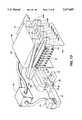
- FIG. 9illustrates a sectional plan view of one-half, of the coupler 60 and the serpentine applicator 100.
- the coupler 60 and the guides 106 and 108are shown on the same plane as the serpentine applicator 100 for illustration.
- the interior of the serially interconnected generally parallel guide sections 120a through 120h joined by U-shaped connecting sections 124is also shown.
- Each guide section 120is connected to the next and partially separated therefrom by a member 122.
- the connecting sections 124transmit the microwave power from one guide section to the next guide section with minimum reflections and loss of power.
- a sheet of paperenters through a slot 126 which is substantially similar to the slot 110 previously described and exits through the slot 110.
- Paper guide memberscomprising microwave transparent material such as TeflonTM or polytetraflouroethylene string are attached to the underneath side of the top half of the serpentine applicator 100 from one slot to the other slot to prevent paper from being caught therein when passing from the slot 126 to the slot 110.
- TeflonTMis hydrophobic and consequently does not disturb the ink.
- Both the slot 126 and the slot 110are surrounded by a lip member 128 shown in FIGS. 6 and 10. Only one half of the lip is illustrated in FIG. 9.
- the lip member 128comprising one-half on the top half and one-half on the bottom half of the serpentine applicator serves as a guide and also as a choke for preventing leakage of microwave power from the serpentine applicator 100.
- the ratio of electric field strength, in the first guide section 120a to electric field strength in the last guide section 120his approximately 2 to 1.
- paper printed with inks having rapid penetration ratesmay be input to the slot 126 and exit the slot 110 to apply the greatest amount of power to the ink/paper as soon as possible.
- Paper printed with inks having slow penetrating ratesmay be input to the slot 110 and exit the slot 126 so that the amount of microwave power applied to the ink/paper increases as the paper travels through the applicator 100.
- FIG. 10further illustrates the slot 110 and the lip member 128.
- the slot 110is tapered at each end as illustrated.
- the length of the slot from the end of the taper to the other end of the taperis eight and one/half inches long shown as dimension A.
- the height of the slotis 0.25 inches shown as dimension B.
- the tapers located at either end of slot 110begin to taper approximately 0.5 inch from the ends. This dimension is shown as C.
- each of the slotsis surrounded by the lip 128 previously described.
- the combination of the tapered slot 110 and the lip 128reduce both VSWR and leakage.
- the lip 128minimizes microwave radiation leakage less than 1 mW/sq. cm.
- the lipserves as a waveguide beyond cutoff for those modes which may be excited in the slot 110.
- the microwave applicator 100is further optimized for the efficient application of microwave power by the U-shaped connecting sections 124 that connect the parallel guide sections 120.
- a preferred embodiment of the connection of parallel guide sections 120 by the U-shaped connecting section 124is illustrated in FIG. 11.
- a single inner wall 142separates the parallel guide sections 120.
- the first, second, and third pieces 136, 138, and 140comprise the U-shaped guide section 124.
- the first and third piece 136 and 140are angled at 135 degrees with respect to the walls 134.
- FIG. 12is a plot of the VSWR versus cut distance. Cut distance is the distance in inches from the end of the second piece 138 at point A to the wall 134 at point B. As illustrated in FIG. 12, as the cut distance approaches 1.4 inches, the VSWR is also reduced in the waveguide having branches with the dimensions of 2.84 inches in height and 0.67 inches in width.
- the single inner wall 142is dimensioned to have a width which is sufficiently wide to choke off any microwave energy from passing from one of the parallel guide sections to another of the parallel guide sections traveling through the slots in the inner walls 142.
- the single inner wall 142has a width of one-sixteenth of an inch. Double walls are also possible wherein each of the guide sections 120 has a wall and the walls of adjacent guide sections are spaced apart.
- FIG. 13illustrates the microwave dryer 28 including a manifold 150 which sits atop the serpentine applicator 100.
- the applicator 100is hinged at locations 130 and 131 to provide access to the interior thereof for paper removal if necessary.
- the applicator 100 and manifold 150are shown in a raised position.
- the manifold 150supplies forced hot air to the top surface of the paper to provide convective hot air drying. Hot air is scavenged from the magnetron 40 and the matching termination 80 and forced by a blower 151 into the manifold 150.
- the manifold 150is shaped like a wedge in which the height at the portion receiving forced air from the blower 151 is greater than the height at the distant end thereof.
- the serpentine applicatormay be opened without being obstructed by the manifold due to any frame or machine which may be located above the manifold 150.
- the hot airpasses through a plurality of holes 152 and/or slots 153 defined in the top of the serpentine applicator 100 as illustrated in FIG. 14.
- FIG. 14also illustrates the interior of the serpentine applicator located above the side of paper having wet ink. Hot air impinges upon the wet surface of the sheet of paper through the holes 152 and slots 153.
- a plurality of microwave transparent baffles 154made of a microwave transparent material such as polystyrene, directs the flow of air to the sheet. Air is removed by means of a vacuum transport which is located below the bottom half of the applicator.
- the holes and slotsare sized to reduce or prevent microwave leakage from and/or reflections in the waveguides 120.
- the holesare 3 mm in diameter and the slots are 3 mm wide and 9 mm long.
- Other combinations of holes and slotscan be used, but it has been found the slots allow for increased air flow to a sheet of paper for drying.
- a minimum of approximately 150 watts of thermal poweris potentially available from the matched loads and the magnetron due to its inherent inefficiencies.
- the magnitude of the power available from the matched loaddepends on the area coverage of ink on the paper. For instance, with low area coverage (20%) approximately 250 watts is dissipated in the termination and for high area coverage (greater than 60%) less than 50 watts is dumped into the matching termination. Thus energy from the termination 80 is not fixed.
- the amount of power dissipated in the matching termination 80depends on the amount of ink deposited on the sheet 14 and the type of coupler 60. It is possible to design a system in which no power is dissipated in the matching termination 80 if the amount of ink deposited on the paper is a known quantity each time. In such a system, the coupler 60 can be designed to couple the required amount of power to the applicator 100 so that no excess power is absorbed by the termination 80. If the ink covered paper is not a matched load, then microwave power which is absorbed in the termination and converted to thermal power can be recycled for convective drying. Consequently, since ink coverage varies over a wide range, the present invention has a wide latitude in drying all types of printed sheets.
- a microwave drying apparatushaving the features of the present invention incorporated herein is capable of controlling paper deformation caused by printing with liquid inks.
- the application of microwave energy to such an ink-laden substrateeffectively prevents the formation of cockle and other paper deforming conditions.
Landscapes
- Physics & Mathematics (AREA)
- Electromagnetism (AREA)
- Health & Medical Sciences (AREA)
- General Health & Medical Sciences (AREA)
- Toxicology (AREA)
- Ink Jet (AREA)
- Drying Of Solid Materials (AREA)
- Accessory Devices And Overall Control Thereof (AREA)
- Supply, Installation And Extraction Of Printed Sheets Or Plates (AREA)
Abstract
Description
Claims (41)
Priority Applications (2)
| Application Number | Priority Date | Filing Date | Title |
|---|---|---|---|
| US08/159,908US5631685A (en) | 1993-11-30 | 1993-11-30 | Apparatus and method for drying ink deposited by ink jet printing |
| JP6287797AJPH07195683A (en) | 1993-11-30 | 1994-11-22 | Ink drying device and method for ink jet printer |
Applications Claiming Priority (1)
| Application Number | Priority Date | Filing Date | Title |
|---|---|---|---|
| US08/159,908US5631685A (en) | 1993-11-30 | 1993-11-30 | Apparatus and method for drying ink deposited by ink jet printing |
Publications (1)
| Publication Number | Publication Date |
|---|---|
| US5631685Atrue US5631685A (en) | 1997-05-20 |
Family
ID=22574623
Family Applications (1)
| Application Number | Title | Priority Date | Filing Date |
|---|---|---|---|
| US08/159,908Expired - LifetimeUS5631685A (en) | 1993-11-30 | 1993-11-30 | Apparatus and method for drying ink deposited by ink jet printing |
Country Status (2)
| Country | Link |
|---|---|
| US (1) | US5631685A (en) |
| JP (1) | JPH07195683A (en) |
Cited By (64)
| Publication number | Priority date | Publication date | Assignee | Title |
|---|---|---|---|---|
| US6089702A (en)* | 1999-01-19 | 2000-07-18 | Xerox Corporation | Method and apparatus for degassing ink utilizing microwaves |
| US6149327A (en)* | 1999-12-22 | 2000-11-21 | Hewlett-Packard Company | Method and apparatus for determining and controlling inkjet printing drying time |
| US6203151B1 (en)* | 1999-06-08 | 2001-03-20 | Hewlett-Packard Company | Apparatus and method using ultrasonic energy to fix ink to print media |
| US6224203B1 (en)* | 1999-05-13 | 2001-05-01 | Hewlett-Packard Company | Hard copy print media path for reducing cockle |
| EP1101621A1 (en)* | 1999-11-18 | 2001-05-23 | Eastman Kodak Company | Inkjet printer having accelerated print drying |
| WO2001089835A2 (en) | 2000-05-25 | 2001-11-29 | Encad, Inc. | Microwave energy ink drying system and method |
| US6425663B1 (en) | 2000-05-25 | 2002-07-30 | Encad, Inc. | Microwave energy ink drying system |
| US6428161B1 (en)* | 2001-04-30 | 2002-08-06 | Hewlett-Packard Company | Drying apparatus |
| US6428159B1 (en) | 1999-07-19 | 2002-08-06 | Xerox Corporation | Apparatus for achieving high quality aqueous ink-jet printing on plain paper at high print speeds |
| US6444964B1 (en) | 2000-05-25 | 2002-09-03 | Encad, Inc. | Microwave applicator for drying sheet material |
| US6450712B1 (en)* | 2001-01-29 | 2002-09-17 | Xerox Corporation | Method and apparatus for optimizing substrate speed in a printer device |
| US6508550B1 (en) | 2000-05-25 | 2003-01-21 | Eastman Kodak Company | Microwave energy ink drying method |
| US6578959B1 (en)* | 2000-06-30 | 2003-06-17 | Hewlett-Packard Development Company, L.P. | Printer including microwave dryer |
| US20030154620A1 (en)* | 2002-02-15 | 2003-08-21 | International Business Machines Corporation | Method and apparatus for electromagnetic drying of printed media |
| US20030160852A1 (en)* | 2002-02-28 | 2003-08-28 | Pickup Ray L. | Ink assist air knife |
| US6612240B1 (en)* | 2000-09-15 | 2003-09-02 | Silverbrook Research Pty Ltd | Drying of an image on print media in a modular commercial printer |
| US6663239B2 (en) | 2001-10-31 | 2003-12-16 | Hewlett-Packard Development Company, L.P. | Microwave applicator for inkjet printer |
| US6683287B2 (en)* | 2000-12-22 | 2004-01-27 | Nexpress Solutions Llc | Process and device for fixing toner onto a substrate or printed material |
| US6686573B2 (en)* | 2000-12-22 | 2004-02-03 | Nexpress Solutions Llc | Process and device for warming up printing material and/or toner |
| US20040218962A1 (en)* | 2002-07-25 | 2004-11-04 | Kia Silverbrook | Print engine having a pair of feed rollers and a print zone proximal thereto |
| US6827435B2 (en) | 2002-01-07 | 2004-12-07 | Xerox Corporation | Moving air jet image conditioner for liquid ink |
| US6866378B2 (en) | 2002-10-28 | 2005-03-15 | Hewlett-Packard Development Company, L.P. | Conductive additives for use in printing processes employing radiational drying |
| US20050073565A1 (en)* | 2003-08-08 | 2005-04-07 | Kia Silverbrook | Print engine for a pagewidth inkjet printer |
| AU2005203477B2 (en)* | 2000-09-13 | 2005-10-06 | Zamtec Limited | Modular printer with ink drying means for print media |
| US20060096480A1 (en)* | 2004-09-25 | 2006-05-11 | Techno-Graphica Gmbh | Device for heat-treating a coating of flat-bed offset printing plates |
| US20060168299A1 (en)* | 2004-12-20 | 2006-07-27 | Yamaha Corporation | Music contents providing apparatus and program |
| EP1217461A3 (en)* | 2000-12-22 | 2006-11-15 | Eastman Kodak Company | Method and unit for fixing toner on a support, in particular a printing support |
| EP1217462A3 (en)* | 2000-12-22 | 2006-11-15 | Eastman Kodak Company | Method and unit for heating printing support and/or toner |
| US20070046723A1 (en)* | 2005-08-25 | 2007-03-01 | Seiko Epson Corporation | Liquid ejection apparatus |
| US20070101609A1 (en)* | 2003-07-30 | 2007-05-10 | Bsh Bosch Und Siemens Hausgerate Gmbh | Method for operating a device with at least one partial programme step of drying |
| US20070175061A1 (en)* | 2005-11-23 | 2007-08-02 | The Sherwin-Williams Company | System and Method to Control Energy Input to a Material |
| US20080155765A1 (en)* | 2006-12-28 | 2008-07-03 | Kimberly-Clark Worldwide, Inc. | Process for dyeing a textile web |
| US20080155764A1 (en)* | 2006-12-28 | 2008-07-03 | Kimberly-Clark Worldwide, Inc. | Process for dyeing a textile web |
| US20080156427A1 (en)* | 2006-12-28 | 2008-07-03 | Kimberly-Clark Worldwide, Inc. | Process For Bonding Substrates With Improved Microwave Absorbing Compositions |
| US20090031579A1 (en)* | 2007-07-31 | 2009-02-05 | Piatt Michael J | Micro-structured drying for inkjet printers |
| US20090165223A1 (en)* | 2007-12-27 | 2009-07-02 | Kimberly-Clark Worldwide, Inc. | Process for applying one or more treatment agents to a textile web |
| US20090184987A1 (en)* | 2008-01-21 | 2009-07-23 | Seiko Epson Corporation | Recording apparatus in which recording medium is heated and method for the same |
| US7568251B2 (en) | 2006-12-28 | 2009-08-04 | Kimberly-Clark Worldwide, Inc. | Process for dyeing a textile web |
| EP2085227A1 (en)* | 2008-01-31 | 2009-08-05 | Mimaki Engineering Co., Ltd. | Inkjet printer and printing method |
| EP2138316A1 (en)* | 2008-06-26 | 2009-12-30 | Mimaki Engineering Co., Ltd. | Inkjet printer and printing method |
| US20090322843A1 (en)* | 2008-06-25 | 2009-12-31 | Mimaki Engineering Co., Ltd. | Inkjet printer and ink dryer |
| EP2143562A1 (en)* | 2008-07-07 | 2010-01-13 | Mimaki Engineering Co., Ltd. | Inkjet printer and printing method |
| US20100053291A1 (en)* | 2008-08-28 | 2010-03-04 | Seiko Epson Corporation | Printing apparatus |
| US20100157504A1 (en)* | 2008-12-20 | 2010-06-24 | Alvin Marion Post | Electrostatic blower systems |
| US20100302318A1 (en)* | 2008-10-07 | 2010-12-02 | Mimaki Engineering Co., Ltd. | Inkjet printer |
| US20110115864A1 (en)* | 2008-07-31 | 2011-05-19 | Domingo Rohde | Method for drying a printing substrate and/or a printing medium located thereon and a printing machine |
| DE102009058960A1 (en)* | 2009-12-18 | 2011-06-22 | Eastman Kodak Co., N.Y. | Apparatus and method for applying and fixing a toner image on a substrate |
| US8182552B2 (en) | 2006-12-28 | 2012-05-22 | Kimberly-Clark Worldwide, Inc. | Process for dyeing a textile web |
| US20120212532A1 (en)* | 2004-08-06 | 2012-08-23 | Seccombe S Dana | Means For Higher Speed Inkjet Printing |
| US20130134155A1 (en)* | 2011-11-28 | 2013-05-30 | The Doshisha | Microwave Heating Device and Image Fixing Apparatus Using the Same |
| US9068775B2 (en) | 2009-02-09 | 2015-06-30 | Heat Technologies, Inc. | Ultrasonic drying system and method |
| US9272301B2 (en) | 2013-03-01 | 2016-03-01 | S. Dana Seccombe | Apparatus and method for non-contact manipulation, conditioning, shaping and drying of surfaces |
| US9358809B2 (en) | 2014-01-24 | 2016-06-07 | Palo Alto Research Center Incorporated | Microwave drying of ink for an ink jet printer |
| US9387698B2 (en) | 2014-07-24 | 2016-07-12 | Xerox Corporation | Printer convection dryer |
| US9671166B2 (en) | 2014-07-24 | 2017-06-06 | Heat Technologies, Inc. | Acoustic-assisted heat and mass transfer device |
| US9849708B1 (en) | 2017-02-23 | 2017-12-26 | Ricoh Company, Ltd. | Microwave dryer of a print system with modulation of the microwave source using frequency shift keying |
| US9975276B2 (en) | 2015-11-11 | 2018-05-22 | Xerox Corporation | System and method for removing support structure from three-dimensional printed objects using microwave energy |
| US10052901B1 (en)* | 2017-02-20 | 2018-08-21 | Ricoh Company, Ltd. | Multi-pass microwave dryers for printing systems |
| US20180244076A1 (en)* | 2017-02-26 | 2018-08-30 | Ricoh Company, Ltd. | Selectively powering multiple microwave energy sources of a dryer for a printing system |
| US10118205B2 (en) | 2015-11-11 | 2018-11-06 | Xerox Corporation | System and method for removing support structure from three-dimensional printed objects using microwave energy |
| US10137632B2 (en) | 2015-11-11 | 2018-11-27 | Xerox Corporation | Method of removing support structure using integrated fluid paths |
| US10350873B2 (en) | 2015-11-11 | 2019-07-16 | Xerox Corporation | System and method for removing support structure from three-dimensional printed objects using microwave energy and nanoparticles |
| US10488108B2 (en) | 2014-07-01 | 2019-11-26 | Heat Technologies, Inc. | Indirect acoustic drying system and method |
| US10821747B1 (en)* | 2019-06-10 | 2020-11-03 | Xerox Corporation | Printer having an aqueous ink drying system that attenuates image quality defects |
Families Citing this family (8)
| Publication number | Priority date | Publication date | Assignee | Title |
|---|---|---|---|---|
| JPH10323974A (en) | 1997-03-25 | 1998-12-08 | Canon Inc | Ink jet recording method and apparatus, and fixing heating element used in the apparatus |
| JP3472470B2 (en)* | 1998-01-27 | 2003-12-02 | シャープ株式会社 | Ink jet recording device |
| JP6512529B2 (en) | 2014-10-22 | 2019-05-15 | 株式会社リコー | Inkjet image forming apparatus |
| JP6443031B2 (en) | 2014-12-17 | 2018-12-26 | 株式会社リコー | Drying apparatus and inkjet image forming apparatus |
| JP2018126990A (en)* | 2017-01-20 | 2018-08-16 | イマジニアリング株式会社 | Printer |
| JP2018122561A (en)* | 2017-02-03 | 2018-08-09 | 株式会社Screenホールディングス | Image recorder, drying device and image recording method |
| US11619446B2 (en) | 2020-09-08 | 2023-04-04 | Wave Power Technology Inc. | Microwave drying device and processing box thereof |
| JP7086154B2 (en)* | 2020-10-05 | 2022-06-17 | 宏碩系統股▲フン▼有限公司 | Microwave dryer and its processing box |
Citations (31)
| Publication number | Priority date | Publication date | Assignee | Title |
|---|---|---|---|---|
| GB1050493A (en)* | ||||
| US2560903A (en)* | 1949-08-27 | 1951-07-17 | Raytheon Mfg Co | Wave guide dielectric heating apparatus |
| US3434220A (en)* | 1967-10-10 | 1969-03-25 | Exxon Research Engineering Co | Microwave drying process for synthetic polymers |
| US3463894A (en)* | 1966-07-08 | 1969-08-26 | Canadian Patents Dev | Microwave drying system using phase shifters |
| US3471672A (en)* | 1967-04-28 | 1969-10-07 | Varian Associates | Slotted waveguide applicator |
| US3584389A (en)* | 1969-02-03 | 1971-06-15 | Hirst Microwave Heating Ltd | Print drying |
| US3617953A (en)* | 1971-03-16 | 1971-11-02 | Canadian Patents Dev | Microwave impedance matching system |
| US3672066A (en)* | 1970-10-30 | 1972-06-27 | Bechtel Int Corp | Microwave drying apparatus |
| US3739130A (en)* | 1972-05-25 | 1973-06-12 | Guardian Packaging Corp | Multi cavity microwave applicator |
| US3783414A (en)* | 1973-02-06 | 1974-01-01 | Westinghouse Electric Corp | Liquid dielectric cooled terminations |
| US3796973A (en)* | 1971-10-18 | 1974-03-12 | Westinghouse Electric Corp | Terminations |
| JPS55107490A (en)* | 1979-02-14 | 1980-08-18 | Fujitsu Ltd | Water ink drying method |
| US4234775A (en)* | 1978-08-17 | 1980-11-18 | Technical Developments, Inc. | Microwave drying for continuously moving webs |
| US4286135A (en)* | 1979-10-09 | 1981-08-25 | Raytheon Company | Compact microwave isolator |
| US4332091A (en)* | 1979-06-08 | 1982-06-01 | C. G. R. Mev | Microwave drying device for drying products in form of grains |
| US4352691A (en)* | 1979-10-17 | 1982-10-05 | Shinshu Seiki Kabushiki Kaisha | Liquid ink for printers |
| EP0089288A1 (en)* | 1982-03-16 | 1983-09-21 | Etablissement Public dit: CENTRE NATIONAL DE LA RECHERCHE SCIENTIFIQUE (CNRS) | Device for heating sheet products by microwaves |
| US4469026A (en)* | 1979-09-20 | 1984-09-04 | Ibm Corporation | Method and apparatus for controlling drying and detaching of printed material |
| US4482239A (en)* | 1981-04-25 | 1984-11-13 | Canon Kabushiki Kaisha | Image recorder with microwave fixation |
| US4754238A (en)* | 1986-04-14 | 1988-06-28 | Max-Planck-Gesellschaft Zur Foerderung Der Wissenschaften E.V. | Microwave absorber using gaseous cooling fluid |
| US4970528A (en)* | 1988-11-02 | 1990-11-13 | Hewlett-Packard Company | Method for uniformly drying ink on paper from an ink jet printer |
| US5079507A (en)* | 1989-01-30 | 1992-01-07 | Daihen Corporation | Automatic impedance adjusting apparatus for microwave load and automatic impedance adjusting method therefor |
| EP0538071A2 (en)* | 1991-10-18 | 1993-04-21 | Canon Kabushiki Kaisha | Ink jet apparatus provided with a fixing mechanism |
| US5207824A (en)* | 1992-04-16 | 1993-05-04 | Hewlett-Packard Company | Formulation for control of paper cockle in thermal ink-jet printing |
| US5214442A (en)* | 1991-09-27 | 1993-05-25 | Xerox Corporation | Adaptive dryer control for ink jet processors |
| US5220346A (en)* | 1992-02-03 | 1993-06-15 | Xerox Corporation | Printing processes with microwave drying |
| US5278375A (en)* | 1990-03-07 | 1994-01-11 | Microondes Energie Systemes | Microwave applicator device for the treatment of sheet or lap products |
| US5349905A (en)* | 1992-03-24 | 1994-09-27 | Xerox Corporation | Method and apparatus for controlling peak power requirements of a printer |
| US5371531A (en)* | 1992-11-12 | 1994-12-06 | Xerox Corporation | Thermal ink-jet printing with fast- and slow-drying inks |
| US5410283A (en)* | 1993-11-30 | 1995-04-25 | Xerox Corporation | Phase shifter for fine tuning a microwave applicator |
| US5422463A (en)* | 1993-11-30 | 1995-06-06 | Xerox Corporation | Dummy load for a microwave dryer |
- 1993
- 1993-11-30USUS08/159,908patent/US5631685A/ennot_activeExpired - Lifetime
- 1994
- 1994-11-22JPJP6287797Apatent/JPH07195683A/enactivePending
Patent Citations (31)
| Publication number | Priority date | Publication date | Assignee | Title |
|---|---|---|---|---|
| GB1050493A (en)* | ||||
| US2560903A (en)* | 1949-08-27 | 1951-07-17 | Raytheon Mfg Co | Wave guide dielectric heating apparatus |
| US3463894A (en)* | 1966-07-08 | 1969-08-26 | Canadian Patents Dev | Microwave drying system using phase shifters |
| US3471672A (en)* | 1967-04-28 | 1969-10-07 | Varian Associates | Slotted waveguide applicator |
| US3434220A (en)* | 1967-10-10 | 1969-03-25 | Exxon Research Engineering Co | Microwave drying process for synthetic polymers |
| US3584389A (en)* | 1969-02-03 | 1971-06-15 | Hirst Microwave Heating Ltd | Print drying |
| US3672066A (en)* | 1970-10-30 | 1972-06-27 | Bechtel Int Corp | Microwave drying apparatus |
| US3617953A (en)* | 1971-03-16 | 1971-11-02 | Canadian Patents Dev | Microwave impedance matching system |
| US3796973A (en)* | 1971-10-18 | 1974-03-12 | Westinghouse Electric Corp | Terminations |
| US3739130A (en)* | 1972-05-25 | 1973-06-12 | Guardian Packaging Corp | Multi cavity microwave applicator |
| US3783414A (en)* | 1973-02-06 | 1974-01-01 | Westinghouse Electric Corp | Liquid dielectric cooled terminations |
| US4234775A (en)* | 1978-08-17 | 1980-11-18 | Technical Developments, Inc. | Microwave drying for continuously moving webs |
| JPS55107490A (en)* | 1979-02-14 | 1980-08-18 | Fujitsu Ltd | Water ink drying method |
| US4332091A (en)* | 1979-06-08 | 1982-06-01 | C. G. R. Mev | Microwave drying device for drying products in form of grains |
| US4469026A (en)* | 1979-09-20 | 1984-09-04 | Ibm Corporation | Method and apparatus for controlling drying and detaching of printed material |
| US4286135A (en)* | 1979-10-09 | 1981-08-25 | Raytheon Company | Compact microwave isolator |
| US4352691A (en)* | 1979-10-17 | 1982-10-05 | Shinshu Seiki Kabushiki Kaisha | Liquid ink for printers |
| US4482239A (en)* | 1981-04-25 | 1984-11-13 | Canon Kabushiki Kaisha | Image recorder with microwave fixation |
| EP0089288A1 (en)* | 1982-03-16 | 1983-09-21 | Etablissement Public dit: CENTRE NATIONAL DE LA RECHERCHE SCIENTIFIQUE (CNRS) | Device for heating sheet products by microwaves |
| US4754238A (en)* | 1986-04-14 | 1988-06-28 | Max-Planck-Gesellschaft Zur Foerderung Der Wissenschaften E.V. | Microwave absorber using gaseous cooling fluid |
| US4970528A (en)* | 1988-11-02 | 1990-11-13 | Hewlett-Packard Company | Method for uniformly drying ink on paper from an ink jet printer |
| US5079507A (en)* | 1989-01-30 | 1992-01-07 | Daihen Corporation | Automatic impedance adjusting apparatus for microwave load and automatic impedance adjusting method therefor |
| US5278375A (en)* | 1990-03-07 | 1994-01-11 | Microondes Energie Systemes | Microwave applicator device for the treatment of sheet or lap products |
| US5214442A (en)* | 1991-09-27 | 1993-05-25 | Xerox Corporation | Adaptive dryer control for ink jet processors |
| EP0538071A2 (en)* | 1991-10-18 | 1993-04-21 | Canon Kabushiki Kaisha | Ink jet apparatus provided with a fixing mechanism |
| US5220346A (en)* | 1992-02-03 | 1993-06-15 | Xerox Corporation | Printing processes with microwave drying |
| US5349905A (en)* | 1992-03-24 | 1994-09-27 | Xerox Corporation | Method and apparatus for controlling peak power requirements of a printer |
| US5207824A (en)* | 1992-04-16 | 1993-05-04 | Hewlett-Packard Company | Formulation for control of paper cockle in thermal ink-jet printing |
| US5371531A (en)* | 1992-11-12 | 1994-12-06 | Xerox Corporation | Thermal ink-jet printing with fast- and slow-drying inks |
| US5410283A (en)* | 1993-11-30 | 1995-04-25 | Xerox Corporation | Phase shifter for fine tuning a microwave applicator |
| US5422463A (en)* | 1993-11-30 | 1995-06-06 | Xerox Corporation | Dummy load for a microwave dryer |
Non-Patent Citations (4)
| Title |
|---|
| Gilbert M. Elchinger, "Electrostatic Dryer for Ink Jet Printers", Xerox Disclosure Journal, vol. 7, No. 6, Nov./Dec. 1982, pp. 373-375. |
| Gilbert M. Elchinger, Electrostatic Dryer for Ink Jet Printers , Xerox Disclosure Journal, vol. 7, No. 6, Nov./Dec. 1982, pp. 373 375.* |
| Van Kooghnett et al; A Microwave Dryer for Ink Lines; Journal of Microwave Power, 7(4), 1972, pp. 347 351.* |
| Van Kooghnett et al; A Microwave Dryer for Ink Lines; Journal of Microwave Power, 7(4), 1972, pp. 347-351. |
Cited By (197)
| Publication number | Priority date | Publication date | Assignee | Title |
|---|---|---|---|---|
| US6089702A (en)* | 1999-01-19 | 2000-07-18 | Xerox Corporation | Method and apparatus for degassing ink utilizing microwaves |
| US6224203B1 (en)* | 1999-05-13 | 2001-05-01 | Hewlett-Packard Company | Hard copy print media path for reducing cockle |
| US6203151B1 (en)* | 1999-06-08 | 2001-03-20 | Hewlett-Packard Company | Apparatus and method using ultrasonic energy to fix ink to print media |
| US6431702B2 (en) | 1999-06-08 | 2002-08-13 | Hewlett-Packard Company | Apparatus and method using ultrasonic energy to fix ink to print media |
| US6428159B1 (en) | 1999-07-19 | 2002-08-06 | Xerox Corporation | Apparatus for achieving high quality aqueous ink-jet printing on plain paper at high print speeds |
| US6428160B2 (en) | 1999-07-19 | 2002-08-06 | Xerox Corporation | Method for achieving high quality aqueous ink-jet printing on plain paper at high print speeds |
| EP1101621A1 (en)* | 1999-11-18 | 2001-05-23 | Eastman Kodak Company | Inkjet printer having accelerated print drying |
| US6149327A (en)* | 1999-12-22 | 2000-11-21 | Hewlett-Packard Company | Method and apparatus for determining and controlling inkjet printing drying time |
| WO2001089835A2 (en) | 2000-05-25 | 2001-11-29 | Encad, Inc. | Microwave energy ink drying system and method |
| US6425663B1 (en) | 2000-05-25 | 2002-07-30 | Encad, Inc. | Microwave energy ink drying system |
| WO2001089835A3 (en)* | 2000-05-25 | 2002-08-15 | Encad Inc | Microwave energy ink drying system and method |
| US6444964B1 (en) | 2000-05-25 | 2002-09-03 | Encad, Inc. | Microwave applicator for drying sheet material |
| US6508550B1 (en) | 2000-05-25 | 2003-01-21 | Eastman Kodak Company | Microwave energy ink drying method |
| US6578959B1 (en)* | 2000-06-30 | 2003-06-17 | Hewlett-Packard Development Company, L.P. | Printer including microwave dryer |
| AU2005203477B2 (en)* | 2000-09-13 | 2005-10-06 | Zamtec Limited | Modular printer with ink drying means for print media |
| US7284822B2 (en) | 2000-09-15 | 2007-10-23 | Silverbrook Research Pty Ltd | Printhead assembly having modular ink distribution |
| US7878629B2 (en) | 2000-09-15 | 2011-02-01 | Silverbrook Research Pty Ltd | Stackable printer module with two pairs of printheads |
| US8113650B2 (en) | 2000-09-15 | 2012-02-14 | Silverbrook Resesarch Pty Ltd | Printer having arcuate printhead |
| US20110199451A1 (en)* | 2000-09-15 | 2011-08-18 | Silverbrook Research Pty Ltd | Printer having arcuate printhead |
| US6612240B1 (en)* | 2000-09-15 | 2003-09-02 | Silverbrook Research Pty Ltd | Drying of an image on print media in a modular commercial printer |
| US7959281B2 (en)* | 2000-09-15 | 2011-06-14 | Silverbrook Research Pty Ltd | Simultaneous duplex digital printer |
| US7946702B2 (en) | 2000-09-15 | 2011-05-24 | Silverbrook Research Pty Ltd | Printer incorporating partially arcuate printhead |
| US7901067B2 (en) | 2000-09-15 | 2011-03-08 | Silverbrook Research Pty Ltd. | Print media loading mechanism having displaceable endless belts |
| US20040027437A1 (en)* | 2000-09-15 | 2004-02-12 | Kia Silverbrook | Printer with printhead close to the media |
| US20040028446A1 (en)* | 2000-09-15 | 2004-02-12 | Kia Silverbrook | Gas supply to a printhead chip |
| US20040028445A1 (en)* | 2000-09-15 | 2004-02-12 | Kia Silverbrook | Elongate printhead assembly including multiple fluid supply galleries |
| US20040032437A1 (en)* | 2000-09-15 | 2004-02-19 | Kia Silverbrook | Continuous media printer including memory for buffering pages |
| US20040032439A1 (en)* | 2000-09-15 | 2004-02-19 | Kia Silverbrook | Modular print engine controllers |
| US20040032478A1 (en)* | 2000-09-15 | 2004-02-19 | Kia Silverbrook | Continuous media printer with downstream drying |
| US20040032475A1 (en)* | 2000-09-15 | 2004-02-19 | Kia Silverbrook | Fixative drying of fluid printed by an inkjet type printer |
| US20040032476A1 (en)* | 2000-09-15 | 2004-02-19 | Silverbrook Research Pty Ltd | Forced drying of printed ink |
| US7857536B2 (en) | 2000-09-15 | 2010-12-28 | Silverbrook Research Pty Ltd | Lockable printer |
| US6752549B2 (en) | 2000-09-15 | 2004-06-22 | Silverbrook Research Pty Ltd | Print engine for a modular commercial printer |
| US6805049B2 (en) | 2000-09-15 | 2004-10-19 | Silverbrook Research Pty Ltd | Drying of an image on print media in a commercial printer |
| US7845791B2 (en) | 2000-09-15 | 2010-12-07 | Kia Silverbrook | Double sided printer module with a pair of endless drying belts |
| US7810902B2 (en) | 2000-09-15 | 2010-10-12 | Silverbrook Research Pty Ltd | Inkjet printer having printed media transport of drying length |
| US6860664B2 (en) | 2000-09-15 | 2005-03-01 | Silverbrook Research Pty Ltd | Printer with printhead close to the media |
| US7806611B2 (en) | 2000-09-15 | 2010-10-05 | Silverbrook Research Pty Ltd | Modular printer having a print engine with two opposed arcuate printheads feeding media at a predetermined rate |
| US20050056177A1 (en)* | 2000-09-15 | 2005-03-17 | Kia Silverbrook | Modular commercial printer |
| US20050062788A1 (en)* | 2000-09-15 | 2005-03-24 | Kia Silverbrook | High volume printing assembly |
| US20050062821A1 (en)* | 2000-09-15 | 2005-03-24 | Kia Silverbrook | Double-sided print engine assembly |
| US20050062823A1 (en)* | 2000-09-15 | 2005-03-24 | Kia Silverbrook | Printer with an ink drying arrangement |
| US20050068370A1 (en)* | 2000-09-15 | 2005-03-31 | Kia Silverbrook | Printhead assembly |
| US7771019B2 (en) | 2000-09-15 | 2010-08-10 | Silverbrook Research Pty Ltd | Stackable printer module for effecting double-sided printing |
| US20050073568A1 (en)* | 2000-09-15 | 2005-04-07 | Kia Silverbrook | Print media air drying inkjet printer |
| US20050093915A1 (en)* | 2000-09-15 | 2005-05-05 | Kia Silverbrook | Double-sided printer |
| US20050099483A1 (en)* | 2000-09-15 | 2005-05-12 | Kia Silverbrook | Printing zone with closely located printhead and media |
| US20050099484A1 (en)* | 2000-09-15 | 2005-05-12 | Kia Silverbrook | Printing path having closely coupled media rollers and printhead |
| US20050099481A1 (en)* | 2000-09-15 | 2005-05-12 | Kia Silverbrook | Print media loading mechanism for a printer |
| US6899480B2 (en) | 2000-09-15 | 2005-05-31 | Silverbrook Research Pty Ltd | Close coupled printhead and media rollers |
| US20100149271A1 (en)* | 2000-09-15 | 2010-06-17 | Silverbrook Research Pty Ltd. | Modular, duplexed printer with substantially identical printhead assemblies |
| US20050140766A1 (en)* | 2000-09-15 | 2005-06-30 | Kia Silverbrook | Drying equipment for high speed printer |
| US20050140756A1 (en)* | 2000-09-15 | 2005-06-30 | Kia Silverbrook | Printhead assembly having modular ink distribution |
| US20050157135A1 (en)* | 2000-09-15 | 2005-07-21 | Kia Silverbrook | Print engine |
| US6926455B2 (en) | 2000-09-15 | 2005-08-09 | Silverbrook Research Pty Ltd | Continuous media printer including memory for buffering pages |
| US6925935B2 (en) | 2000-09-15 | 2005-08-09 | Silverbrook Research Pty Ltd | Gas supply to a printhead chip |
| US20100149270A1 (en)* | 2000-09-15 | 2010-06-17 | Silverbrook Research Pty Ltd | Modular printer assembly with arcuate printheads |
| US6948870B2 (en) | 2000-09-15 | 2005-09-27 | Silverbrook Research Pty Ltd | Print media loading mechanism for a printer |
| US20100134563A1 (en)* | 2000-09-15 | 2010-06-03 | Silverbrook Research Pty Ltd | Modular Printer With Arcuate Printheads |
| US20050238400A1 (en)* | 2000-09-15 | 2005-10-27 | Silverbrook Research Pty Ltd | Inkjet printer having associated printhead, control and memory modules |
| US6964533B2 (en) | 2000-09-15 | 2005-11-15 | Silverbrook Research Pty Ltd | Printing zone with closely located printhead and media |
| US6966636B2 (en) | 2000-09-15 | 2005-11-22 | Silverbrook Research Pty Ltd | Elongate printhead assembly including multiple fluid supply galleries |
| US6971313B2 (en) | 2000-09-15 | 2005-12-06 | Silverbrook Research Pty Ltd | Forced drying of printed ink |
| US7677682B2 (en) | 2000-09-15 | 2010-03-16 | Silverbrook Research Pty Ltd | Modular printer with substantially identical duplexed printhead assemblies |
| US20050275702A1 (en)* | 2000-09-15 | 2005-12-15 | Silverbrook Research Pty Ltd | Printer for duplex printing with multiple printhead modules |
| US6981809B2 (en) | 2000-09-15 | 2006-01-03 | Silverbrook Research Pty Ltd | Printing path having closely coupled media rollers and printhead |
| US6988845B2 (en) | 2000-09-15 | 2006-01-24 | Silverbrook Research Pty Ltd | Modular commercial printer |
| US20060029454A1 (en)* | 2000-09-15 | 2006-02-09 | Silverbrook Research Pty Ltd. | Printhead assembly for use proximate a drive roller nip |
| US7371024B2 (en) | 2000-09-15 | 2008-05-13 | Silverbrook Research Pty Ltd | Printhead assembly |
| US20060067775A1 (en)* | 2000-09-15 | 2006-03-30 | Silverbrook Research Pty Ltd | Modular printhead assembly with opposed sets of serially arranged printhead modules |
| US20060067779A1 (en)* | 2000-09-15 | 2006-03-30 | Silverbrook Research Pty Ltd | Modular printer for double-sided high-speed printing |
| US7021843B2 (en) | 2000-09-15 | 2006-04-04 | Silverbrook Research Pty Ltd | Modular print engine controllers |
| US7024995B2 (en) | 2000-09-15 | 2006-04-11 | Silverbrook Research Pty Ltd | Continuous media printer with downstream drying |
| US7673967B2 (en) | 2000-09-15 | 2010-03-09 | Silverbrook Research Pty Ltd | Modular printer assembly with a loading mechanism |
| US20080105152A1 (en)* | 2000-09-15 | 2008-05-08 | Silverbrook Research Pty Ltd | Modular Printer With A Print Media Drying Housing |
| US7070257B2 (en) | 2000-09-15 | 2006-07-04 | Silverbrook Research Pty Ltd | Double-sided printer |
| US7077590B2 (en) | 2000-09-15 | 2006-07-18 | Kia Silverbrook | Printhead assembly for use proximate a drive roller nip |
| US7648294B2 (en) | 2000-09-15 | 2010-01-19 | Silverbrook Research Pty Ltd | Modular printer with a print media drying housing |
| US20090273644A1 (en)* | 2000-09-15 | 2009-11-05 | Silverbrook Research Pty Ltd | Modular Printer With Printheads Proximate Feed Roller Nip |
| US7364286B2 (en) | 2000-09-15 | 2008-04-29 | Silverbrook Research Pty Ltd | Print engine incorporating a quartet of printhead modules arranged in pairs |
| US20090237481A1 (en)* | 2000-09-15 | 2009-09-24 | Silverbrook Research Pty Ltd | Printer Incorporating Partially Arcuate Printhead |
| US7566125B2 (en) | 2000-09-15 | 2009-07-28 | Silverbrook Research Pty Ltd | Print engine with printheads located proximal to a pinching zone |
| US7556369B2 (en) | 2000-09-15 | 2009-07-07 | Silverbrook Research Pty Ltd | Printer with set spacing between a print engine and an exit roller assembly |
| US7195336B2 (en) | 2000-09-15 | 2007-03-27 | Silverbrook Research Pty Ltd | High volume printing assembly |
| US20090123211A1 (en)* | 2000-09-15 | 2009-05-14 | Silverbrook Research Pty Ltd | Lockable printer |
| US7472989B2 (en) | 2000-09-15 | 2009-01-06 | Silverbrook Research Pty Ltd | Print media loading mechanism having displaceable endless belts |
| US20070109388A1 (en)* | 2000-09-15 | 2007-05-17 | Silverbrook Research Pty Ltd | Ink jet printer with a belt-loading mechanism |
| US7222940B2 (en) | 2000-09-15 | 2007-05-29 | Silverbrook Research Pty Ltd | Print engine |
| US7222941B2 (en) | 2000-09-15 | 2007-05-29 | Silverbrook Research Pty Ltd | Printer for duplex printing with multiple printhead modules |
| US7226159B2 (en) | 2000-09-15 | 2007-06-05 | Silverbrook Research Pty Ltd | Printer with an ink drying arrangement |
| US20070139503A1 (en)* | 2000-09-15 | 2007-06-21 | Silverbrook Research Pty Ltd. | Print engine with printheads located proximal to a pinching zone |
| US20070172295A1 (en)* | 2000-09-15 | 2007-07-26 | Silverbrook Research Pty Ltd | Print engine with end moldings |
| US7249904B2 (en) | 2000-09-15 | 2007-07-31 | Silverbrook Research Pty Ltd | Modular printer for double-sided high-speed printing |
| US20090000501A1 (en)* | 2000-09-15 | 2009-01-01 | Silverbrook Research Pty Ltd | Modular printer assembly with a loading mechanism |
| US7258067B2 (en) | 2000-09-15 | 2007-08-21 | Silverbrook Research Pty Ltd | Drying equipment for high speed printer |
| US20070217854A1 (en)* | 2000-09-15 | 2007-09-20 | Silverbrook Research Pty Ltd | Simultaneous duplex digital printer |
| US7278795B2 (en) | 2000-09-15 | 2007-10-09 | Silverbrook Research Pty Ltd | Modular printhead assembly with opposed sets of serially arranged printhead modules |
| US7284925B2 (en) | 2000-09-15 | 2007-10-23 | Silverbrook Research Pty Ltd | Printer module for a printing array |
| US7467903B2 (en) | 2000-09-15 | 2008-12-23 | Silverbrook Research Pty Ltd | Print engine with end moldings |
| US7284852B2 (en) | 2000-09-15 | 2007-10-23 | Silverbrook Research Pty Ltd | Fixative drying of fluid printed by an inkjet type printer |
| US20070280770A1 (en)* | 2000-09-15 | 2007-12-06 | Silverbrook Research Pty Ltd | Modular Printer With Substantially Identical Duplexed Printhead Assemblies |
| US20080012902A1 (en)* | 2000-09-15 | 2008-01-17 | Silverbrook Research Pty Ltd | Stackable printer module for effecting double-sided printing |
| US20080012901A1 (en)* | 2000-09-15 | 2008-01-17 | Silverbrook Research Pty Ltd | Stackable printer module with two pairs of printheads |
| US7322757B2 (en) | 2000-09-15 | 2008-01-29 | Silverbrook Research Pty Ltd | Inkjet printer having associated printhead, control and memory modules |
| US7329061B2 (en) | 2000-09-15 | 2008-02-12 | Silverbrook Research Pty Ltd | Ink jet printer with a belt-loading mechanism |
| US7441866B2 (en) | 2000-09-15 | 2008-10-28 | Silverbrook Research Pty Ltd | Print media air drying inkjet printer |
| US20080252687A1 (en)* | 2000-09-15 | 2008-10-16 | Silverbrook Research Pty Ltd | Inkjet printer having printed media transport of drying length |
| US20060033798A1 (en)* | 2000-09-15 | 2006-02-16 | Silverbrook Research Pty Ltd | Printer module for a printing array |
| US20080240836A1 (en)* | 2000-09-15 | 2008-10-02 | Silverbrook Research Pty Ltd | Double sided printer module with a pair of endless drying belts |
| US20080159801A1 (en)* | 2000-09-15 | 2008-07-03 | Silverbrook Research Pty Ltd | Print media loading mechanism having displaceable endless belts |
| US20080193189A1 (en)* | 2000-09-15 | 2008-08-14 | Silverbrook Research Pty Ltd | Modular printer having a print engine with two opposed arcuate printheads feeding media at a predetermined rate |
| US20080166171A1 (en)* | 2000-09-15 | 2008-07-10 | Silverbrook Research Pty Ltd | Printer with set spacing between a print engine and an exit roller assembly |
| US6686573B2 (en)* | 2000-12-22 | 2004-02-03 | Nexpress Solutions Llc | Process and device for warming up printing material and/or toner |
| EP1217459A3 (en)* | 2000-12-22 | 2006-11-15 | Eastman Kodak Company | Method and unit for fixing toner on a support, in particular a printing support |
| EP1217460A3 (en)* | 2000-12-22 | 2006-11-15 | Eastman Kodak Company | Method and unit for heating a printing support and/or toner |
| EP1217461A3 (en)* | 2000-12-22 | 2006-11-15 | Eastman Kodak Company | Method and unit for fixing toner on a support, in particular a printing support |
| US6683287B2 (en)* | 2000-12-22 | 2004-01-27 | Nexpress Solutions Llc | Process and device for fixing toner onto a substrate or printed material |
| EP1217462A3 (en)* | 2000-12-22 | 2006-11-15 | Eastman Kodak Company | Method and unit for heating printing support and/or toner |
| US6450712B1 (en)* | 2001-01-29 | 2002-09-17 | Xerox Corporation | Method and apparatus for optimizing substrate speed in a printer device |
| US6428161B1 (en)* | 2001-04-30 | 2002-08-06 | Hewlett-Packard Company | Drying apparatus |
| EP1261237A1 (en)* | 2001-04-30 | 2002-11-27 | Hewlett-Packard Company | Drying apparatus |
| US6663239B2 (en) | 2001-10-31 | 2003-12-16 | Hewlett-Packard Development Company, L.P. | Microwave applicator for inkjet printer |
| US6827435B2 (en) | 2002-01-07 | 2004-12-07 | Xerox Corporation | Moving air jet image conditioner for liquid ink |
| US6938358B2 (en)* | 2002-02-15 | 2005-09-06 | International Business Machines Corporation | Method and apparatus for electromagnetic drying of printed media |
| US20040055175A1 (en)* | 2002-02-15 | 2004-03-25 | International Business Machines Corporation | Method and apparatus for electromagnetic drying of printed media |
| US6901683B2 (en)* | 2002-02-15 | 2005-06-07 | International Business Machines Corporation | Method and apparatus for electromagnetic drying of printed media |
| US20030154620A1 (en)* | 2002-02-15 | 2003-08-21 | International Business Machines Corporation | Method and apparatus for electromagnetic drying of printed media |
| US7052124B2 (en) | 2002-02-28 | 2006-05-30 | Hewlett-Packard Development Company, L.P. | Ink assist air knife |
| US20030160852A1 (en)* | 2002-02-28 | 2003-08-28 | Pickup Ray L. | Ink assist air knife |
| US6971811B2 (en) | 2002-07-25 | 2005-12-06 | Silverbrook Research Pty Ltd | Print engine having a pair of feed rollers and a print zone proximal thereto |
| US20040218962A1 (en)* | 2002-07-25 | 2004-11-04 | Kia Silverbrook | Print engine having a pair of feed rollers and a print zone proximal thereto |
| US6866378B2 (en) | 2002-10-28 | 2005-03-15 | Hewlett-Packard Development Company, L.P. | Conductive additives for use in printing processes employing radiational drying |
| US20070101609A1 (en)* | 2003-07-30 | 2007-05-10 | Bsh Bosch Und Siemens Hausgerate Gmbh | Method for operating a device with at least one partial programme step of drying |
| US8601716B2 (en)* | 2003-07-30 | 2013-12-10 | Bsh Bosch Und Siemens Hausgeraete Gmbh | Method for operating a device with at least one partial programme step of drying |
| US20050073565A1 (en)* | 2003-08-08 | 2005-04-07 | Kia Silverbrook | Print engine for a pagewidth inkjet printer |
| US7201523B2 (en) | 2003-08-08 | 2007-04-10 | Silverbrook Research Pty Ltd | Print engine for a pagewidth inkjet printer |
| US8585169B2 (en)* | 2004-08-06 | 2013-11-19 | S Dana Seccombe | Means for higher speed inkjet printing |
| US20120212532A1 (en)* | 2004-08-06 | 2012-08-23 | Seccombe S Dana | Means For Higher Speed Inkjet Printing |
| US20060096480A1 (en)* | 2004-09-25 | 2006-05-11 | Techno-Graphica Gmbh | Device for heat-treating a coating of flat-bed offset printing plates |
| US20060168299A1 (en)* | 2004-12-20 | 2006-07-27 | Yamaha Corporation | Music contents providing apparatus and program |
| US20070046723A1 (en)* | 2005-08-25 | 2007-03-01 | Seiko Epson Corporation | Liquid ejection apparatus |
| US7665820B2 (en)* | 2005-08-25 | 2010-02-23 | Seiko Epson Corporation | Liquid ejection apparatus |
| US20070175061A1 (en)* | 2005-11-23 | 2007-08-02 | The Sherwin-Williams Company | System and Method to Control Energy Input to a Material |
| US7913417B2 (en)* | 2005-11-23 | 2011-03-29 | The Sherwin-Williams Company | System and method to control energy input to a material |
| US20080155765A1 (en)* | 2006-12-28 | 2008-07-03 | Kimberly-Clark Worldwide, Inc. | Process for dyeing a textile web |
| US7740666B2 (en) | 2006-12-28 | 2010-06-22 | Kimberly-Clark Worldwide, Inc. | Process for dyeing a textile web |
| US20080155764A1 (en)* | 2006-12-28 | 2008-07-03 | Kimberly-Clark Worldwide, Inc. | Process for dyeing a textile web |
| US8182552B2 (en) | 2006-12-28 | 2012-05-22 | Kimberly-Clark Worldwide, Inc. | Process for dyeing a textile web |
| US7568251B2 (en) | 2006-12-28 | 2009-08-04 | Kimberly-Clark Worldwide, Inc. | Process for dyeing a textile web |
| US7674300B2 (en) | 2006-12-28 | 2010-03-09 | Kimberly-Clark Worldwide, Inc. | Process for dyeing a textile web |
| US20080156427A1 (en)* | 2006-12-28 | 2008-07-03 | Kimberly-Clark Worldwide, Inc. | Process For Bonding Substrates With Improved Microwave Absorbing Compositions |
| US20090031579A1 (en)* | 2007-07-31 | 2009-02-05 | Piatt Michael J | Micro-structured drying for inkjet printers |
| US7966743B2 (en) | 2007-07-31 | 2011-06-28 | Eastman Kodak Company | Micro-structured drying for inkjet printers |
| US8632613B2 (en) | 2007-12-27 | 2014-01-21 | Kimberly-Clark Worldwide, Inc. | Process for applying one or more treatment agents to a textile web |
| US20090165223A1 (en)* | 2007-12-27 | 2009-07-02 | Kimberly-Clark Worldwide, Inc. | Process for applying one or more treatment agents to a textile web |
| US20090184987A1 (en)* | 2008-01-21 | 2009-07-23 | Seiko Epson Corporation | Recording apparatus in which recording medium is heated and method for the same |
| EP2085227A1 (en)* | 2008-01-31 | 2009-08-05 | Mimaki Engineering Co., Ltd. | Inkjet printer and printing method |
| US20090195626A1 (en)* | 2008-01-31 | 2009-08-06 | Mimaki Engineering Co., Ltd. | Inkjet printer and printing method |
| US8007098B2 (en)* | 2008-01-31 | 2011-08-30 | Mimaki Engineering Co., Ltd. | Inkjet printer and printing method |
| US8136935B2 (en)* | 2008-06-25 | 2012-03-20 | Mimaki Engineering Co., Ltd. | Inkjet printer and ink dryer |
| US20090322843A1 (en)* | 2008-06-25 | 2009-12-31 | Mimaki Engineering Co., Ltd. | Inkjet printer and ink dryer |
| EP2138316A1 (en)* | 2008-06-26 | 2009-12-30 | Mimaki Engineering Co., Ltd. | Inkjet printer and printing method |
| CN101612829B (en)* | 2008-06-26 | 2012-05-02 | 株式会社御牧工程 | Inkjet printer and printing method |
| EP2143562A1 (en)* | 2008-07-07 | 2010-01-13 | Mimaki Engineering Co., Ltd. | Inkjet printer and printing method |
| US20110115864A1 (en)* | 2008-07-31 | 2011-05-19 | Domingo Rohde | Method for drying a printing substrate and/or a printing medium located thereon and a printing machine |
| US20100053291A1 (en)* | 2008-08-28 | 2010-03-04 | Seiko Epson Corporation | Printing apparatus |
| US8342673B2 (en)* | 2008-08-28 | 2013-01-01 | Seiko Epson Corporation | Printing apparatus |
| US8267502B2 (en)* | 2008-10-07 | 2012-09-18 | Mimaki Engineering Co., Ltd. | Inkjet printer |
| US20100302318A1 (en)* | 2008-10-07 | 2010-12-02 | Mimaki Engineering Co., Ltd. | Inkjet printer |
| US20100157504A1 (en)* | 2008-12-20 | 2010-06-24 | Alvin Marion Post | Electrostatic blower systems |
| US8059383B2 (en) | 2008-12-20 | 2011-11-15 | Hewlett-Packard Development Company, L.P. | Electrostatic blower systems |
| US9068775B2 (en) | 2009-02-09 | 2015-06-30 | Heat Technologies, Inc. | Ultrasonic drying system and method |
| US10006704B2 (en) | 2009-02-09 | 2018-06-26 | Heat Technologies, Inc. | Ultrasonic drying system and method |
| US11353263B2 (en) | 2009-02-09 | 2022-06-07 | Heat Technologies, Inc. | Ultrasonic drying system and method |
| US10775104B2 (en) | 2009-02-09 | 2020-09-15 | Heat Technologies, Inc. | Ultrasonic drying system and method |
| DE102009058960A1 (en)* | 2009-12-18 | 2011-06-22 | Eastman Kodak Co., N.Y. | Apparatus and method for applying and fixing a toner image on a substrate |
| US8843048B2 (en) | 2009-12-18 | 2014-09-23 | Eastman Kodak Company | Device and method for applying and fusing a toner image on a substrate |
| US9258850B2 (en)* | 2011-11-28 | 2016-02-09 | Murata Machinery, Ltd. | Microwave heating device and image fixing apparatus using the same |
| US20130134155A1 (en)* | 2011-11-28 | 2013-05-30 | The Doshisha | Microwave Heating Device and Image Fixing Apparatus Using the Same |
| US9272301B2 (en) | 2013-03-01 | 2016-03-01 | S. Dana Seccombe | Apparatus and method for non-contact manipulation, conditioning, shaping and drying of surfaces |
| US9358809B2 (en) | 2014-01-24 | 2016-06-07 | Palo Alto Research Center Incorporated | Microwave drying of ink for an ink jet printer |
| US10488108B2 (en) | 2014-07-01 | 2019-11-26 | Heat Technologies, Inc. | Indirect acoustic drying system and method |
| US10139162B2 (en) | 2014-07-24 | 2018-11-27 | Heat Technologies, Inc. | Acoustic-assisted heat and mass transfer device |
| US9671166B2 (en) | 2014-07-24 | 2017-06-06 | Heat Technologies, Inc. | Acoustic-assisted heat and mass transfer device |
| US9387698B2 (en) | 2014-07-24 | 2016-07-12 | Xerox Corporation | Printer convection dryer |
| US10350873B2 (en) | 2015-11-11 | 2019-07-16 | Xerox Corporation | System and method for removing support structure from three-dimensional printed objects using microwave energy and nanoparticles |
| US10118205B2 (en) | 2015-11-11 | 2018-11-06 | Xerox Corporation | System and method for removing support structure from three-dimensional printed objects using microwave energy |
| US10137632B2 (en) | 2015-11-11 | 2018-11-27 | Xerox Corporation | Method of removing support structure using integrated fluid paths |
| US9975276B2 (en) | 2015-11-11 | 2018-05-22 | Xerox Corporation | System and method for removing support structure from three-dimensional printed objects using microwave energy |
| US10562211B2 (en) | 2015-11-11 | 2020-02-18 | Xerox Corporation | System for removing support structure from three-dimensional printed objects using microwave energy |
| US10710298B2 (en) | 2015-11-11 | 2020-07-14 | Xerox Corporation | System for removing support structure using integrated fluid paths |
| US11318666B2 (en) | 2015-11-11 | 2022-05-03 | Xerox Corporation | System for removing support structure using integrated fluid paths |
| US10052901B1 (en)* | 2017-02-20 | 2018-08-21 | Ricoh Company, Ltd. | Multi-pass microwave dryers for printing systems |
| US9849708B1 (en) | 2017-02-23 | 2017-12-26 | Ricoh Company, Ltd. | Microwave dryer of a print system with modulation of the microwave source using frequency shift keying |
| US10065435B1 (en)* | 2017-02-26 | 2018-09-04 | Ricoh Company, Ltd. | Selectively powering multiple microwave energy sources of a dryer for a printing system |
| US20180244076A1 (en)* | 2017-02-26 | 2018-08-30 | Ricoh Company, Ltd. | Selectively powering multiple microwave energy sources of a dryer for a printing system |
| US10821747B1 (en)* | 2019-06-10 | 2020-11-03 | Xerox Corporation | Printer having an aqueous ink drying system that attenuates image quality defects |
Also Published As
| Publication number | Publication date |
|---|---|
| JPH07195683A (en) | 1995-08-01 |
Similar Documents
| Publication | Publication Date | Title |
|---|---|---|
| US5631685A (en) | Apparatus and method for drying ink deposited by ink jet printing | |
| US5422463A (en) | Dummy load for a microwave dryer | |
| US5410283A (en) | Phase shifter for fine tuning a microwave applicator | |
| US6901683B2 (en) | Method and apparatus for electromagnetic drying of printed media | |
| DE69307010T2 (en) | Air flow system for a thermal inkjet printer | |
| US6463674B1 (en) | Hot air impingement drying system for inkjet images | |
| EP0284215B1 (en) | Method and apparatus for uniformly drying ink on paper from an ink jet printer | |
| US5423260A (en) | Device for heating a printed web for a printing press | |
| DE69310994T2 (en) | Thermal inkjet printer with a heating element, which is supplied with variable thermal energy for different printing media | |
| US20070079719A1 (en) | Ink jet printing and drying a printing material | |
| US6121595A (en) | Applicator to provide uniform electric and magnetic fields over a large area and for continuous processing | |
| US6428161B1 (en) | Drying apparatus | |
| US6665516B2 (en) | Fixation device for fixation of toner material | |
| US6904260B2 (en) | Fixing apparatus and fixing method for a printer | |
| JPS5826979A (en) | Heating and drying device by microwave | |
| JP2003534164A (en) | Microwave energy ink drying system and method | |
| JP3472470B2 (en) | Ink jet recording device | |
| US7298994B2 (en) | Process and printing machine for the use of liquid print colors | |
| JP2000211116A (en) | Ink drying apparatus | |
| JP2004046158A (en) | Method and device for fixing toner on substrate | |
| CA1038458A (en) | Microwave paint dryer | |
| US10052901B1 (en) | Multi-pass microwave dryers for printing systems | |
| YOSHIKADO et al. | Fixing Electrophotographic Toner Particles by Microwave Heating | |
| JP2018158508A (en) | Printer and printing method | |
| US20070211127A1 (en) | Ink-jet printing device including a microwave heating device |
Legal Events
| Date | Code | Title | Description |
|---|---|---|---|
| AS | Assignment | Owner name:XEROX CORPORATION, CONNECTICUT Free format text:ASSIGNMENT OF ASSIGNORS INTEREST;ASSIGNORS:GOORAY, ARTHUR M.;PETER, KENNETH C.;SIRKIS, MURRAY D.;REEL/FRAME:006787/0196 Effective date:19931130 | |
| STCF | Information on status: patent grant | Free format text:PATENTED CASE | |
| FPAY | Fee payment | Year of fee payment:4 | |
| AS | Assignment | Owner name:BANK ONE, NA, AS ADMINISTRATIVE AGENT, ILLINOIS Free format text:SECURITY INTEREST;ASSIGNOR:XEROX CORPORATION;REEL/FRAME:013153/0001 Effective date:20020621 | |
| AS | Assignment | Owner name:JPMORGAN CHASE BANK, AS COLLATERAL AGENT, TEXAS Free format text:SECURITY AGREEMENT;ASSIGNOR:XEROX CORPORATION;REEL/FRAME:015134/0476 Effective date:20030625 Owner name:JPMORGAN CHASE BANK, AS COLLATERAL AGENT,TEXAS Free format text:SECURITY AGREEMENT;ASSIGNOR:XEROX CORPORATION;REEL/FRAME:015134/0476 Effective date:20030625 | |
| FPAY | Fee payment | Year of fee payment:8 | |
| FPAY | Fee payment | Year of fee payment:12 | |
| AS | Assignment | Owner name:XEROX CORPORATION, CONNECTICUT Free format text:RELEASE BY SECURED PARTY;ASSIGNOR:JPMORGAN CHASE BANK, N.A. AS SUCCESSOR-IN-INTEREST ADMINISTRATIVE AGENT AND COLLATERAL AGENT TO JPMORGAN CHASE BANK;REEL/FRAME:066728/0193 Effective date:20220822 |