US5631503A - Apparatus for generating power for use in a communications device - Google Patents
Apparatus for generating power for use in a communications deviceDownload PDFInfo
- Publication number
- US5631503A US5631503AUS08/307,933US30793394AUS5631503AUS 5631503 AUS5631503 AUS 5631503AUS 30793394 AUS30793394 AUS 30793394AUS 5631503 AUS5631503 AUS 5631503A
- Authority
- US
- United States
- Prior art keywords
- battery
- voltage
- transmitter
- power
- coupled
- Prior art date
- Legal status (The legal status is an assumption and is not a legal conclusion. Google has not performed a legal analysis and makes no representation as to the accuracy of the status listed.)
- Expired - Lifetime
Links
- 238000004891communicationMethods0.000titleclaimsabstractdescription38
- 230000005540biological transmissionEffects0.000claimsdescription15
- 238000012545processingMethods0.000claimsdescription15
- 230000007246mechanismEffects0.000claimsdescription11
- 230000005669field effectEffects0.000claimsdescription2
- 238000007599dischargingMethods0.000claims2
- 238000000034methodMethods0.000abstractdescription6
- 238000010248power generationMethods0.000abstractdescription6
- 230000000135prohibitive effectEffects0.000abstractdescription2
- 239000003990capacitorSubstances0.000description6
- HBBGRARXTFLTSG-UHFFFAOYSA-NLithium ionChemical compound[Li+]HBBGRARXTFLTSG-UHFFFAOYSA-N0.000description2
- OJIJEKBXJYRIBZ-UHFFFAOYSA-Ncadmium nickelChemical compound[Ni].[Cd]OJIJEKBXJYRIBZ-UHFFFAOYSA-N0.000description2
- 238000010586diagramMethods0.000description2
- 230000009977dual effectEffects0.000description2
- 229910001416lithium ionInorganic materials0.000description2
- 238000012546transferMethods0.000description2
- 239000002253acidSubstances0.000description1
- 230000004075alterationEffects0.000description1
- 230000008901benefitEffects0.000description1
- 230000001413cellular effectEffects0.000description1
- 238000006243chemical reactionMethods0.000description1
- 229910044991metal oxideInorganic materials0.000description1
- 150000004706metal oxidesChemical class0.000description1
- 238000012986modificationMethods0.000description1
- 230000004048modificationEffects0.000description1
- 239000013307optical fiberSubstances0.000description1
- 230000002093peripheral effectEffects0.000description1
- 230000010363phase shiftEffects0.000description1
- 230000004044responseEffects0.000description1
- 238000005070samplingMethods0.000description1
- 239000004065semiconductorSubstances0.000description1
Images

Classifications
- H—ELECTRICITY
- H02—GENERATION; CONVERSION OR DISTRIBUTION OF ELECTRIC POWER
- H02J—CIRCUIT ARRANGEMENTS OR SYSTEMS FOR SUPPLYING OR DISTRIBUTING ELECTRIC POWER; SYSTEMS FOR STORING ELECTRIC ENERGY
- H02J7/00—Circuit arrangements for charging or depolarising batteries or for supplying loads from batteries
- H02J7/34—Parallel operation in networks using both storage and other DC sources, e.g. providing buffering
- H—ELECTRICITY
- H02—GENERATION; CONVERSION OR DISTRIBUTION OF ELECTRIC POWER
- H02J—CIRCUIT ARRANGEMENTS OR SYSTEMS FOR SUPPLYING OR DISTRIBUTING ELECTRIC POWER; SYSTEMS FOR STORING ELECTRIC ENERGY
- H02J7/00—Circuit arrangements for charging or depolarising batteries or for supplying loads from batteries
- H02J7/0013—Circuit arrangements for charging or depolarising batteries or for supplying loads from batteries acting upon several batteries simultaneously or sequentially
- H—ELECTRICITY
- H04—ELECTRIC COMMUNICATION TECHNIQUE
- H04B—TRANSMISSION
- H04B1/00—Details of transmission systems, not covered by a single one of groups H04B3/00 - H04B13/00; Details of transmission systems not characterised by the medium used for transmission
- H04B1/06—Receivers
- H04B1/16—Circuits
- H04B1/1607—Supply circuits
- H04B1/1615—Switching on; Switching off, e.g. remotely
Definitions
- the field of the inventionrelates to battery power generators; more particularly, the present invention relates to the field of battery-based power generation in communications devices such as wireless communications systems.
- a communication systemtransfers information between a source and a destination.
- a communication systemincludes a transmitter and a receiver which transmit and receive information signals over some media. This media may be cable wiring or atmosphere. When communications occur over atmosphere, or airwaves, they are commonly referred to as "wireless" communications. Examples of wireless communication systems include digital cellular, packet data, paging and digital cordless telephones, wireless modems, wireless local and wide area networks, digital satellite communications and personal communications networks.
- wireless communications equipmentmay be portable. If the equipment is portable, this communication equipment must provide its own source of power, such as a battery unit.
- Typical batteries used in portable devicesmay include AA batteries or AAA batteries producing 1.5 volts. In other portable devices, batteries such as Nickel Cadmium (NiCd) battery cells and lithium-ion battery cells may be used.
- AA or AAA batteriesbecause of their internal series resistance and low voltage, they cannot satisfy the power requirements for certain portable devices.
- a transmitter in a communications devicemay require a high voltage and high current power source to supply bursts of power to function, typically one that generates 3 to 5 watts of power.
- a 1.5 volt AA batterycannot generate this much power.
- One solution for generating more power in a deviceis to increase the size or number of batteries used to power the portable device.
- space in portable devicesis usually at a premium, and the battery size that may be used is often limited to the space available.
- a non-rechargeable battery of the size necessary to produce, for example, 3 to 5 watts,is much larger in size than the current batteries used in the portable devices. Therefore, it is desirable to generate the necessary power. In a device using as little space within the unit as possible.
- Another solution for generating more power in a portable systemis to use a capacitive discharge system wherein a capacitor is charged such that it discharges power at the desired wattage.
- a capacitive discharge systemwherein a capacitor is charged such that it discharges power at the desired wattage.
- problems with using a capacitive discharge system in portable devicesFor instance, either the size of the capacitors which are required are prohibitive given the size constraints of the portable devices or existing capacitors have too much internal resistance. Even though the capacitors have enough capacity to power short transmitter bursts, they do not have enough capacity to power amplifiers in a transmitter for the time required to send a short message, particularly at low data rates typically used in portable wireless communications systems. Also, capacitive discharge systems cannot accommodate worst case duty cycles where a transmitter or other device is repeatedly placed on and off for short periods of time.
- a single capacitorcould not provide bursts of power for a short period of time and then recharge fast enough for currently desired duty cycles. Therefore, using a capacitor discharge scheme limits the size of data packets that could be sent and the time between data packets has to be lengthened to accommodate intervening recharge cycles.
- the present inventionprovides a technique to generate high-current pulses in a small area. This allows the size of a transmitter to be miniaturized specifically for certain applications.
- the apparatuscomprises a first battery (power source), a second battery and a charging mechanism.
- the first battery (power source)supplies power at a first voltage and a first current
- the second batterysupplies power at a second voltage and second current.
- the power from the second batteryis greater than the power from the first battery.
- the charging mechanismcharges the second battery using a third voltage derived from the first battery.
- the charging mechanismincludes an upconverter that converts the first voltage to the third voltage which is large enough to charge the second battery.
- a controllermonitors the second voltage of the second battery and controls the flow of current between the first battery and the second battery, such that the controller causes current to flow from the first battery to the second battery to charge the second battery when the second battery voltage is below a first level and stops the flow of current between the first battery and the second battery when the second battery has been fully charged.
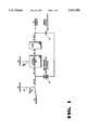
- FIG. 1is a circuit schematic for a battery power generation mechanism of the present invention.
- FIG. 2illustrates a block diagram of an exemplary communication system according to the present invention.
- the present inventionprovides a dual battery system designed to operate from a low voltage primary battery and a secondary rechargeable battery.
- the voltage from the low voltage batterye.g., the primary battery
- the higher voltage batterye.g., the secondary battery
- the secondary batteryis then used to discharge at a higher current and voltage that would be achievable from the low voltage primary battery.
- the primary batterycomprises a 1.5 volt alkaline AA battery or a AAA battery
- the secondary batteryis a rechargeable battery such as a series combination of three 1/3 AA nickel cadmium (NiCd) batteries producing 3.6 volts.
- the volume of the three NiCd batteries combinedis roughly equivalent to the volume of one alkaline AA battery.
- the secondary batterymay be a lithium-ion battery, lead acid battery or other batteries that have a low internal resistance and are rechargeable.
- both the primary battery and the secondary batterymay comprise other battery types.
- the secondary rechargeable batteryis used to discharge into a communications transmitter at a higher current and voltage than the alkaline AA or AAA batteries could achieve. After that transmission or multiple transmissions, the rechargeable secondary battery is recharged again from the primary battery.
- FIG. 1illustrates the power generation technique of the present invention.
- a primary battery 101is shown coupled to provide power to analog and/or digital circuitry (not shown). This circuitry may be located in a portable communications device. In another embodiment, primary battery 101 does not provide power to a portion of the circuitry of the unit.
- the primary battery 101is also coupled to the input of a DC/DC converter 102.
- the output of the DC/DC converter 102is coupled to one input of a battery management unit (BMU) 103.
- BMU 103is also coupled to a controller for the device via bus 104.
- An output of BMU 103is coupled to the output of secondary battery 105.
- the output of secondary battery 105is also coupled to one input of switch 106.
- Switch 106is also coupled to another portion of the circuitry of the device. Switch 106 is controlled via controller signal 107. Also note that one terminal of each of the secondary battery 105 and primary battery 101 are coupled to ground.
- primary battery 101comprises a 1.5 volt AA alkaline cell
- the secondary battery 105comprises 3N-110AA NiCd batteries coupled in series.
- the primary battery 101represents the main replaceable battery in the system, and may be replaced in a manner well-known in the art (e.g., by exchanging cells).
- the secondary battery 105may be replaceable.
- the secondary battery 105is not as accessible as the primary battery 101. For instance, removal of the secondary battery 105 may require removing screws to gain access to the battery's location.
- the DC/DC converter 102is powered by primary battery 101 and converts the voltage produced by the primary battery 101 to a higher voltage necessary to charge the secondary battery 105.
- the DC/DC converter 102receives 1.5 volts at 50 milliamps of current and produces a 5 volt voltage which is received by the BMU 103.
- BMU 103controls the flow of current from the primary battery 101 to the secondary (rechargeable) battery 105 and outputs the 5 volt voltage at 11 milliamps to the secondary battery 105.
- BMU 103allows current to flow from the primary battery 101 to the secondary battery 105.
- the flow of currentmay be controlled using a switch (e.g., a transistor) in BMU 103 that is turned on and off.
- the BMU 103also monitors the voltage of the secondary battery 105 to ensure that it charges correctly. That is, the BMU 103 monitors the voltage and determines when it has reached its peak charging and shuts off the current to the secondary battery 105 from the primary battery 101. In one embodiment, BMU 103 monitors the slope of the voltage curve in a manner well-known in the art and when the slope has attained a certain point (based on the battery type), BMU 103 determines that the battery has reached its peak charging and stops charging the battery. In one embodiment, BMU 103 monitors voltage of the secondary battery 105 using a resistor (e.g., a transistor) in a manner well-known in the art.
- a resistore.g., a transistor
- BMU 103operates in conjunction with an external controller located in the device being powered.
- the external controlleris used to control the BMU 104 and indicate when it is to operate.
- a bus 104 between the external controller and the BMU 103allows for communication of specific information between the two.
- bus 104is bi-directional.
- Bus 104may be used by BMU 103 to indicate to the external controller that it is charging the secondary battery 105.
- bus 104may be used to indicate to the external controller that the secondary battery 104 requires charging.
- Bus 104may also be used by the external controller to indicate to BMU 103 that transmission is to occur and to cause charging to stop to allow for such transmission.
- the bus 104may be used to indicate that the secondary battery 105 is fully charged.
- Switch 106 in the systemis used to disable the secondary battery 105 from the circuitry to which it is providing power when the secondary battery 105 is being charged. This is accomplished by opening the switch 106.
- switch 106comprises a transistor, such as a metal-oxide semiconductor field-effect transistor (MOSFET).
- MOSFETmetal-oxide semiconductor field-effect transistor
- switch 106is controlled by the external controller in the system. For instance, when disabling the power from the secondary battery to the circuitry, the gate of the transistor may receive a voltage causing the transistor to turn off.
- the secondary battery 105is used to power the transmitter in a transceiver.
- the transmitteris operated according to a duty cycle having an "on" period of time followed by an “off” period of time and continually repeating the on and off periods where the sending of data requires multiple transmission periods.
- the duration of the time periodsis variable, with the worst case duty cycle having a 1.2 second "on” period followed by a 0.6 second “off” period (and continually repeating the on/off periods).
- a data packet transferis performed.
- the external controllerturns on switch 106 and indicates to the BMU 103 to stop charging the battery.
- the BMU 103disables current flow to the secondary battery 105 from the primary battery 101.
- the BMU 103still monitors the secondary battery 105 during transmission to determine its voltage level. When the voltage level has dropped to a predetermined low level (and the transmitter is off during its duty cycle), the BMU 103 allows the current to flow between the two batteries to charge the secondary battery 105.
- the voltage from the primary battery 101is converted by the DC/DC converter 102 to 5 volts.
- the voltageis converted to 5 volts because the voltage used to charge the secondary battery 105 must be greater than the voltage produced by the secondary battery 105.
- the secondary batteryis a 3.6 volt battery
- the up-converted 5 volt voltageis able to charge the secondary battery 105.
- the primary battery 101may be also powering the remaining circuitry, or some portion thereof, in the transceiver.
- the BMU 103allows the current to flow to charge the secondary battery 105.
- the BMU 103shuts down the current from the primary battery 101 to the secondary battery 105.
- the external controllerswitches the rechargeable secondary battery 105 to discharge into the transmitter to provide the bursts of high voltage and high current power necessary for the transmission.
- the secondary battery 105generates power with a 2 amp current at 3.6 volts.
- One advantage of the present inventionis that a rechargeable battery with a much lower series resistance than a primary battery can be used to power the transmitter.
- the available voltageis much higher in the dual battery system (over a single battery system)
- the available currentis also much higher as well.
- the discharge pulse time of the systemis limited only by the capacity of the rechargeable battery, thereby allowing long transmission times not achievable with capacitive discharge schemes.
- the sizeis reduced significantly over using a single primary battery system. In an embodiment described above, six AA alkaline cells would be required to generate the power equivalent to that generated by a volume equivalent of 2 AA cells.
- Applicationsinclude wireless communications transceiver where the duration of the transmit time will be short and the size of the portable unit is required to be small, such as in two-way paging and packet radio systems.
- the present inventionis, however, not limited to communications and can be used whenever the power required for the application exceeds that available from a small commonly available battery.
- FIG. 2illustrates a block diagram of an exemplary digital communications system.
- the present inventionis advantageously employed in wireless data communication systems. However, the present invention may be employed in other data communications systems.
- digital communications system 200comprises transmitter 210 and receiver 211.
- Transmitter 210includes data processing block 201 (optional), modulator 202, amplifier 203, antenna 204, and power supply 214, (such as shown in FIG. 1).
- Power supply 214provides power to components of transmitter 210.
- Data processing block 201is coupled to receive a message 220.
- the output of data processing block 201is coupled to the input of modulator 202.
- the output of modulator 202is coupled to input of amplifier 203.
- the output of amplifier 203is coupled to transmitting antenna 204.
- the output from transmitting antenna 204is radiated into the transmission medium and subsequently received by receiver antenna 208 of receiver 211.
- the output of receiver antenna 208is coupled to the input of low-noise amplifier 207.
- the output of low-noise amplifier 207is coupled to the input of demodulator 206.
- the output of demodulator 206is coupled to the input of data processing block 205 (optional).
- the output of data processing block 205is message 220.
- Power supply 215, such as shown in FIG. 1,provides power to components in receiver 211. Note that controller logic coordinating the operations of the components has not been shown to avoid obscuring the present invention.
- Transmitter 210transmits the signals throughout the digital communications system.
- Message signal 220is initially received at the input of transmitter 210 and filtered to eliminate undesired components. Then, assuming message signal 220 is suitable for transmission, data processing block 201 samples message signal 220 and performs any necessary analog-to-digital conversion.
- Data processing block 201may perform encoding, and any peripheral functions, such as output, displays, storage, etc.
- the output of data processing block 201is a group of binary symbols. These binary symbols may undergo source coding.
- the digitized output symbols from data processing block 201are then modulated onto a carrier.
- a parameter of the carriersuch as amplitude, frequency or phase, is modulated by the digital symbols.
- the modulation scheme of the present inventionmay be one of the many well-known modulation techniques, such as frequency shift keying, phase shift keying, amplitude shift keying (or on-off keying), and their many variations.
- the modulated signal output from modulator 202is amplified by amplifier 203 and input to the channel, wherein the modulated signals are transferred to their destination.
- the channelincludes transmitting antenna 204, the space between transmitter 210 and receiver 211, and receiving antenna 208.
- the channelmay include airwaves, cables, optical fiber, or other means for transferring the signals between transmitter 210 and receiver 211.
- the signalis amplified by low-noise amplifier 207, demodulated by demodulator 206, and then processed by data processing block 205 (if required) to reproduce message 220, where data processing block performs any desired output, display, or storage functions as well as any desired decoding.
- data processing 201controls sampling of the data stream.
- digital communication system 200is shown with only a small set of components, other components may be included in the system.
- coders and decodersmay be employed in transmitter 210 and receiver 211 respectively.
- transmitter 210 and receiver 211are shown as individual components, each may be part of a transceiver capable of performing both the transmit and receive functions.
- amplifier 203 as part of the transmitter 210receives power generated by one battery (e.g., battery 105 in FIG. 1) while the remainder of the transmitter 210 is powered by another battery (e.g., battery 101 in FIG. 1).
- the power supplied to amplifier 203is higher than that generated by the other battery that powers the remainder of transmitter 210.
- power supply 215functions in the same manner with respect to the receiver and amplifier 207 as power supply 214.
Landscapes
- Engineering & Computer Science (AREA)
- Power Engineering (AREA)
- Charge And Discharge Circuits For Batteries Or The Like (AREA)
Abstract
Description
Claims (28)
Priority Applications (1)
| Application Number | Priority Date | Filing Date | Title |
|---|---|---|---|
| US08/307,933US5631503A (en) | 1994-09-16 | 1994-09-16 | Apparatus for generating power for use in a communications device |
Applications Claiming Priority (1)
| Application Number | Priority Date | Filing Date | Title |
|---|---|---|---|
| US08/307,933US5631503A (en) | 1994-09-16 | 1994-09-16 | Apparatus for generating power for use in a communications device |
Publications (1)
| Publication Number | Publication Date |
|---|---|
| US5631503Atrue US5631503A (en) | 1997-05-20 |
Family
ID=23191801
Family Applications (1)
| Application Number | Title | Priority Date | Filing Date |
|---|---|---|---|
| US08/307,933Expired - LifetimeUS5631503A (en) | 1994-09-16 | 1994-09-16 | Apparatus for generating power for use in a communications device |
Country Status (1)
| Country | Link |
|---|---|
| US (1) | US5631503A (en) |
Cited By (30)
| Publication number | Priority date | Publication date | Assignee | Title |
|---|---|---|---|---|
| EP0975081A2 (en)* | 1998-07-22 | 2000-01-26 | Sharp Kabushiki Kaisha | A power supply circuit and a disk drive device provided with same |
| US6153949A (en)* | 1998-03-17 | 2000-11-28 | Telefonaktiebolaget Lm Ericsson | Electrical power management system providing momentarily high power to a load |
| US6411062B1 (en)* | 1999-09-21 | 2002-06-25 | Sony Corporation | Quick release battery and clip for portable device and method of implementing same |
| US6473630B1 (en)* | 1999-10-22 | 2002-10-29 | Sony Corporation | Method and apparatus for powering a wireless headset used with a personal electronic device |
| US20030035308A1 (en)* | 2001-07-23 | 2003-02-20 | Northern Power Systems, Inc. | Control system for a power converter and method of controlling operation of a power converter |
| US20030052547A1 (en)* | 2001-03-01 | 2003-03-20 | Fischer Daniel M. | Multifunctional charger system and method |
| US20030054703A1 (en)* | 2001-03-01 | 2003-03-20 | Fischer Daniel M. | System and method for powering and charging a mobile communication device |
| US6628107B1 (en) | 2001-10-31 | 2003-09-30 | Symbol Technologies, Inc. | Power management for a portable electronic device |
| US6661975B1 (en)* | 2000-03-10 | 2003-12-09 | Northrop Grumman Corporation | Multi-rate variable duty cycle modem for use in an optical communication system |
| US20040121793A1 (en)* | 2002-12-24 | 2004-06-24 | Weigele Ingo W. | Methods and apparatus for controlling power to electrical circuitry of a wireless communication device having a subscriber identity module (SIM) interface |
| US20040164708A1 (en)* | 2003-02-21 | 2004-08-26 | Dusan Veselic | Circuit and method of operation for an electrical power supply |
| US20040164707A1 (en)* | 2003-02-21 | 2004-08-26 | Dusan Veselic | Circuit and method of operation for an adaptive charge rate power supply |
| US6856654B1 (en) | 1997-09-15 | 2005-02-15 | Research In Motion Limited | Power supply system for a packet-switched radio transmitter |
| US20050046384A1 (en)* | 2000-11-06 | 2005-03-03 | Simoes Felipe Oliveira | Portable battery charger |
| US7038333B2 (en) | 2002-02-15 | 2006-05-02 | The Gillette Company | Hybrid power supply |
| US20060193095A1 (en)* | 2002-09-26 | 2006-08-31 | Hunter Phillip M | Modular battery management apparatus with cell sensing and energy redistribution capabilities |
| WO2008046600A3 (en)* | 2006-10-17 | 2008-09-25 | Wilo Ag | Method for transmitting data and data transmission device for remote control and/or remote inquiry |
| US20110043033A1 (en)* | 2009-08-19 | 2011-02-24 | Microelectronics Technology Inc. | Out-Door Unit with Multiple Ports |
| US20110143699A1 (en)* | 2009-12-10 | 2011-06-16 | Lg Electronics Inc. | Method and apparatus for transmitting data in wireless communication system |
| US20110175452A1 (en)* | 2010-01-21 | 2011-07-21 | Tomonori Hoshino | Power supply device and method of controlling the same |
| US20120235485A1 (en)* | 2011-03-18 | 2012-09-20 | Medtronic Minimed, Inc. | Power control techniques for an electronic device |
| US20130255335A1 (en)* | 2012-03-28 | 2013-10-03 | Master Lock Company | Systems and methods for electronic locking device power management |
| US20140368486A1 (en)* | 2006-12-28 | 2014-12-18 | Semiconductor Energy Laboratory Co., Ltd. | Display device |
| US20150333513A1 (en)* | 2012-11-09 | 2015-11-19 | Volvo Truck Corporation | Power supply device |
| US20160020632A1 (en)* | 2014-07-18 | 2016-01-21 | Honda Motor Co., Ltd. | Keyless entry device and method for powering the keyless entry device |
| EP2932575A4 (en)* | 2012-11-20 | 2016-12-07 | Badger Meter Inc | System and method for improving chemical efficiency of a battery in a flow measurement system |
| CN107863571A (en)* | 2017-10-13 | 2018-03-30 | 常州普莱德新能源电池科技有限公司 | A kind of electrokinetic cell parameter acquisition system |
| US10224831B1 (en) | 2018-01-22 | 2019-03-05 | Northern Power Systems, Inc. | Control systems, methods, and software for keeping power converters within operating limits during disturbances |
| US11061058B2 (en)* | 2006-11-16 | 2021-07-13 | Semiconductor Energy Laboratory Co., Ltd. | Radio field intensity measurement device, and radio field intensity detector and game console using the same |
| US20230291217A1 (en)* | 2022-03-10 | 2023-09-14 | Itron, Inc. | Operations management of battery-powered devices |
Citations (6)
| Publication number | Priority date | Publication date | Assignee | Title |
|---|---|---|---|---|
| US4504861A (en)* | 1982-02-18 | 1985-03-12 | Emcee A Division Of Electronics, Missiles & Communications, Inc. | Portable TV transmitter |
| US4939770A (en)* | 1987-07-16 | 1990-07-03 | Nec Corporation | Cordless telephone with battery saving function |
| US5130634A (en)* | 1989-07-05 | 1992-07-14 | Nec Corporation | Battery charger for a portable wireless telephone set having means for tricklingly charging the battery with an increased current during a stand-by period of the telephone set |
| US5237259A (en)* | 1990-11-13 | 1993-08-17 | Sony Corporation | Charging method for secondary battery |
| US5391974A (en)* | 1990-10-15 | 1995-02-21 | Toshiba Battery Co., Ltd. | Secondary battery charging circuit |
| US5455637A (en)* | 1993-09-10 | 1995-10-03 | Comdisco, Inc. | Electrochromic eyewear system, rechargeable eyewear and external charger therefor |
- 1994
- 1994-09-16USUS08/307,933patent/US5631503A/ennot_activeExpired - Lifetime
Patent Citations (6)
| Publication number | Priority date | Publication date | Assignee | Title |
|---|---|---|---|---|
| US4504861A (en)* | 1982-02-18 | 1985-03-12 | Emcee A Division Of Electronics, Missiles & Communications, Inc. | Portable TV transmitter |
| US4939770A (en)* | 1987-07-16 | 1990-07-03 | Nec Corporation | Cordless telephone with battery saving function |
| US5130634A (en)* | 1989-07-05 | 1992-07-14 | Nec Corporation | Battery charger for a portable wireless telephone set having means for tricklingly charging the battery with an increased current during a stand-by period of the telephone set |
| US5391974A (en)* | 1990-10-15 | 1995-02-21 | Toshiba Battery Co., Ltd. | Secondary battery charging circuit |
| US5237259A (en)* | 1990-11-13 | 1993-08-17 | Sony Corporation | Charging method for secondary battery |
| US5455637A (en)* | 1993-09-10 | 1995-10-03 | Comdisco, Inc. | Electrochromic eyewear system, rechargeable eyewear and external charger therefor |
Cited By (70)
| Publication number | Priority date | Publication date | Assignee | Title |
|---|---|---|---|---|
| US6856654B1 (en) | 1997-09-15 | 2005-02-15 | Research In Motion Limited | Power supply system for a packet-switched radio transmitter |
| US6153949A (en)* | 1998-03-17 | 2000-11-28 | Telefonaktiebolaget Lm Ericsson | Electrical power management system providing momentarily high power to a load |
| EP0975081A2 (en)* | 1998-07-22 | 2000-01-26 | Sharp Kabushiki Kaisha | A power supply circuit and a disk drive device provided with same |
| US6411062B1 (en)* | 1999-09-21 | 2002-06-25 | Sony Corporation | Quick release battery and clip for portable device and method of implementing same |
| US6473630B1 (en)* | 1999-10-22 | 2002-10-29 | Sony Corporation | Method and apparatus for powering a wireless headset used with a personal electronic device |
| US6661975B1 (en)* | 2000-03-10 | 2003-12-09 | Northrop Grumman Corporation | Multi-rate variable duty cycle modem for use in an optical communication system |
| US7554285B2 (en) | 2000-11-06 | 2009-06-30 | Research In Motion Limited | Portable battery charger |
| US7268519B2 (en) | 2000-11-06 | 2007-09-11 | Research In Motion Limited | Portable battery charger for a mobile device |
| US20050046384A1 (en)* | 2000-11-06 | 2005-03-03 | Simoes Felipe Oliveira | Portable battery charger |
| US20100148724A1 (en)* | 2001-03-01 | 2010-06-17 | Research In Motion Limited | System and Method for Charging a Battery in a Mobile Device |
| US7239111B2 (en) | 2001-03-01 | 2007-07-03 | Research In Motion Limited | Universal serial bus adapter for a mobile device |
| US20030052547A1 (en)* | 2001-03-01 | 2003-03-20 | Fischer Daniel M. | Multifunctional charger system and method |
| US8624550B2 (en) | 2001-03-01 | 2014-01-07 | Blackberry Limited | Multifunctional charger system and method |
| US8232766B2 (en) | 2001-03-01 | 2012-07-31 | Research In Motion Limited | Multifunctional charger system and method |
| US8169187B2 (en) | 2001-03-01 | 2012-05-01 | Research In Motion Limited | Multifunctional charger system and method |
| US20090058359A1 (en)* | 2001-03-01 | 2009-03-05 | Research In Motion Limited | Multifunction Charger System and Method |
| US7986127B2 (en) | 2001-03-01 | 2011-07-26 | Research In Motion Limited | Communication device with a USB port for charging |
| US7453233B2 (en) | 2001-03-01 | 2008-11-18 | Research In Motion Limited | Adapter system and method for powering a device |
| US6936936B2 (en) | 2001-03-01 | 2005-08-30 | Research In Motion Limited | Multifunctional charger system and method |
| US6946817B2 (en) | 2001-03-01 | 2005-09-20 | Research In Motion Limited | System and method for powering and charging a mobile communication device |
| US20050245138A1 (en)* | 2001-03-01 | 2005-11-03 | Fischer Daniel M | Multifunctional charger system and method |
| US20110025262A1 (en)* | 2001-03-01 | 2011-02-03 | Research In Motion Limited | Multifunctional Charger System and Method |
| US7834586B2 (en) | 2001-03-01 | 2010-11-16 | Research In Motion Limited | Multifunctional charger system and method |
| US20100171463A9 (en)* | 2001-03-01 | 2010-07-08 | Research In Motion Limited | System and method for charging a battery in a mobile device |
| US20070216353A1 (en)* | 2001-03-01 | 2007-09-20 | Research In Motion Limited | Multifunction Charger System and Method |
| US7737657B2 (en) | 2001-03-01 | 2010-06-15 | Research In Motion Limited | System and method for charging a battery in a mobile device |
| US20030054703A1 (en)* | 2001-03-01 | 2003-03-20 | Fischer Daniel M. | System and method for powering and charging a mobile communication device |
| US7145266B2 (en) | 2001-07-23 | 2006-12-05 | Northern Power Systems, Inc. | Parallel-connected inverters with separate controllers having impedance current regulators |
| US20030035308A1 (en)* | 2001-07-23 | 2003-02-20 | Northern Power Systems, Inc. | Control system for a power converter and method of controlling operation of a power converter |
| US6693409B2 (en)* | 2001-07-23 | 2004-02-17 | Northern Power Systems, Inc. | Control system for a power converter and method of controlling operation of a power converter |
| US20040145357A1 (en)* | 2001-07-23 | 2004-07-29 | Lynch Jonathan A. | Control system for a power converter and method of controlling operation of a power converter |
| US6628107B1 (en) | 2001-10-31 | 2003-09-30 | Symbol Technologies, Inc. | Power management for a portable electronic device |
| US7038333B2 (en) | 2002-02-15 | 2006-05-02 | The Gillette Company | Hybrid power supply |
| US7579842B2 (en)* | 2002-09-26 | 2009-08-25 | Eaton Power Quality Company | Battery management apparatus |
| US20060193095A1 (en)* | 2002-09-26 | 2006-08-31 | Hunter Phillip M | Modular battery management apparatus with cell sensing and energy redistribution capabilities |
| US20040121793A1 (en)* | 2002-12-24 | 2004-06-24 | Weigele Ingo W. | Methods and apparatus for controlling power to electrical circuitry of a wireless communication device having a subscriber identity module (SIM) interface |
| US7847520B2 (en) | 2003-02-21 | 2010-12-07 | Research In Motion Limited | Circuit and method of operation for an electrical power supply |
| US8541983B2 (en) | 2003-02-21 | 2013-09-24 | Blackberry Limited | Circuit and method of operation for an electrical power supply |
| US20100219797A1 (en)* | 2003-02-21 | 2010-09-02 | Research In Motion Limited | Circuit and Method of Operation for an Electrical Power Supply |
| US7034503B2 (en) | 2003-02-21 | 2006-04-25 | Research In Motion Limited | Circuit and method of operation for an adaptive charge rate power supply |
| US7791319B2 (en) | 2003-02-21 | 2010-09-07 | Research In Motion Limited | Circuit and method of operation for an electrical power supply |
| US20050046391A1 (en)* | 2003-02-21 | 2005-03-03 | Research In Motion Limited | Circuit and method of operation for an adaptive charge rate power supply |
| US6833686B2 (en)* | 2003-02-21 | 2004-12-21 | Research In Motion Limited | Circuit and method of operation for an adaptive charge rate power supply |
| US20040164707A1 (en)* | 2003-02-21 | 2004-08-26 | Dusan Veselic | Circuit and method of operation for an adaptive charge rate power supply |
| US20040164708A1 (en)* | 2003-02-21 | 2004-08-26 | Dusan Veselic | Circuit and method of operation for an electrical power supply |
| WO2008046600A3 (en)* | 2006-10-17 | 2008-09-25 | Wilo Ag | Method for transmitting data and data transmission device for remote control and/or remote inquiry |
| US11656258B2 (en) | 2006-11-16 | 2023-05-23 | Semiconductor Energy Laboratory Co., Ltd. | Radio field intensity measurement device, and radio field intensity detector and game console using the same |
| US11061058B2 (en)* | 2006-11-16 | 2021-07-13 | Semiconductor Energy Laboratory Co., Ltd. | Radio field intensity measurement device, and radio field intensity detector and game console using the same |
| US20140368486A1 (en)* | 2006-12-28 | 2014-12-18 | Semiconductor Energy Laboratory Co., Ltd. | Display device |
| US8368245B2 (en)* | 2009-08-19 | 2013-02-05 | Microelectronics Technology, Inc. | Out-door unit with multiple ports |
| US20110043033A1 (en)* | 2009-08-19 | 2011-02-24 | Microelectronics Technology Inc. | Out-Door Unit with Multiple Ports |
| US20110143699A1 (en)* | 2009-12-10 | 2011-06-16 | Lg Electronics Inc. | Method and apparatus for transmitting data in wireless communication system |
| US8467836B2 (en)* | 2009-12-10 | 2013-06-18 | Lg Electronics Inc. | Method and apparatus for transmitting data in wireless communication system |
| US9054556B2 (en)* | 2010-01-21 | 2015-06-09 | Nec Corporation | Power supply device and method of controlling the same |
| US20110175452A1 (en)* | 2010-01-21 | 2011-07-21 | Tomonori Hoshino | Power supply device and method of controlling the same |
| US9755452B2 (en) | 2011-03-18 | 2017-09-05 | Medtronic Minimed, Inc. | Power control techniques for an electronic device |
| US9018893B2 (en)* | 2011-03-18 | 2015-04-28 | Medtronic Minimed, Inc. | Power control techniques for an electronic device |
| US20120235485A1 (en)* | 2011-03-18 | 2012-09-20 | Medtronic Minimed, Inc. | Power control techniques for an electronic device |
| US20130255335A1 (en)* | 2012-03-28 | 2013-10-03 | Master Lock Company | Systems and methods for electronic locking device power management |
| US20150333513A1 (en)* | 2012-11-09 | 2015-11-19 | Volvo Truck Corporation | Power supply device |
| US9831671B2 (en)* | 2012-11-09 | 2017-11-28 | Volvo Truck Corporation | Power supply device |
| EP2932575A4 (en)* | 2012-11-20 | 2016-12-07 | Badger Meter Inc | System and method for improving chemical efficiency of a battery in a flow measurement system |
| US9910094B2 (en)* | 2012-11-20 | 2018-03-06 | Badger Meter, Inc. | System and method for improving chemical efficiency of a battery in a flow measurement system |
| US20200021141A1 (en)* | 2014-07-18 | 2020-01-16 | Honda Motor Co., Ltd. | Keyless entry device and method for powering the keyless entry device |
| US10454315B2 (en)* | 2014-07-18 | 2019-10-22 | Honda Motor Co., Ltd. | Keyless entry device and method for powering the keyless entry device |
| US10855113B2 (en)* | 2014-07-18 | 2020-12-01 | Honda Motor Co., Ltd. | Keyless entry device and method for powering the keyless entry device |
| US20160020632A1 (en)* | 2014-07-18 | 2016-01-21 | Honda Motor Co., Ltd. | Keyless entry device and method for powering the keyless entry device |
| CN107863571A (en)* | 2017-10-13 | 2018-03-30 | 常州普莱德新能源电池科技有限公司 | A kind of electrokinetic cell parameter acquisition system |
| US10224831B1 (en) | 2018-01-22 | 2019-03-05 | Northern Power Systems, Inc. | Control systems, methods, and software for keeping power converters within operating limits during disturbances |
| US20230291217A1 (en)* | 2022-03-10 | 2023-09-14 | Itron, Inc. | Operations management of battery-powered devices |
Similar Documents
| Publication | Publication Date | Title |
|---|---|---|
| US5631503A (en) | Apparatus for generating power for use in a communications device | |
| EP0654911B1 (en) | Switch-mode power supply for time division multiple access radio phone systems | |
| EP1201006B1 (en) | Rechargeable battery packs | |
| US5859522A (en) | Accessory identification apparatus and method | |
| US9893552B2 (en) | Charging circuits, charging systems, and wireless power reception devices including the same | |
| CA2247102C (en) | Improved power supply system for a packet-switched radio transmitter | |
| US4709201A (en) | Portable radio battery pack with on-off switch | |
| US6140807A (en) | Electronic device and associated method for charging an energy storage circuit with a DC-DC converter | |
| US5925942A (en) | Power supply control apparatus and method suitable for use in an electronic device | |
| CN101447684A (en) | Wireless power charging system | |
| US5628054A (en) | Portable radio apparatus having batteries for supplying a plurality of voltages | |
| JP3158833B2 (en) | Mobile radio equipment | |
| JP2002330095A (en) | Base station, base station control method, and mobile communication system | |
| US5005198A (en) | Cordless telephone apparatus | |
| WO1995006994A1 (en) | Tracking external power supply | |
| KR100487622B1 (en) | Device and the Method for variating the charging current of battery | |
| US20230369882A1 (en) | Parallel battery charger | |
| JP2000078766A (en) | Portable electronic devices and charging circuits | |
| RU2263384C2 (en) | Universal intelligent mobile phone battery charger | |
| KR20020063050A (en) | Cordless charging system for mobile-phone | |
| KR100222428B1 (en) | Battery charging current control device and method by portable unit | |
| JP4774981B2 (en) | Charging device and portable electronic device | |
| US20130099578A1 (en) | Method of operating a mobile device, apparatus and wireless device | |
| GB2309360A (en) | Portable terminal power supply with primary and secondary cells | |
| RU2180465C1 (en) | Emergency power supply for cellular radiophones |
Legal Events
| Date | Code | Title | Description |
|---|---|---|---|
| AS | Assignment | Owner name:WIRELESS ACCESS, INC., CALIFORNIA Free format text:ASSIGNMENT OF ASSIGNORS INTEREST;ASSIGNOR:CIOFFI, KENNETH R.;REEL/FRAME:007158/0826 Effective date:19940912 | |
| FEPP | Fee payment procedure | Free format text:PAYOR NUMBER ASSIGNED (ORIGINAL EVENT CODE: ASPN); ENTITY STATUS OF PATENT OWNER: LARGE ENTITY | |
| FPAY | Fee payment | Year of fee payment:4 | |
| AS | Assignment | Owner name:GLENAYRE ELECTRONICS, INC., GEORGIA Free format text:ASSIGNMENT OF ASSIGNORS INTEREST;ASSIGNOR:WIRELESS ACCESS, INC.;REEL/FRAME:012569/0116 Effective date:20011025 | |
| AS | Assignment | Owner name:PERCOMM, INC., MASSACHUSETTS Free format text:ASSIGNMENT OF ASSIGNORS INTEREST;ASSIGNOR:GLENAYRE ELECTRONICS INC.;REEL/FRAME:013705/0772 Effective date:20020507 | |
| AS | Assignment | Owner name:GLENAYRE ELECTRONICS, INC., GEORGIA Free format text:STATEMENT OF SECURITY INTEREST IN PATENT RIGHTS;ASSIGNOR:PERCOMM, INC.;REEL/FRAME:015541/0899 Effective date:20020102 | |
| REMI | Maintenance fee reminder mailed | ||
| REIN | Reinstatement after maintenance fee payment confirmed | ||
| LAPS | Lapse for failure to pay maintenance fees | Free format text:PATENT EXPIRED FOR FAILURE TO PAY MAINTENANCE FEES (ORIGINAL EVENT CODE: EXP.); ENTITY STATUS OF PATENT OWNER: LARGE ENTITY | |
| FP | Lapsed due to failure to pay maintenance fee | Effective date:20050520 | |
| FEPP | Fee payment procedure | Free format text:PETITION RELATED TO MAINTENANCE FEES GRANTED (ORIGINAL EVENT CODE: PMFG); ENTITY STATUS OF PATENT OWNER: LARGE ENTITY | |
| FEPP | Fee payment procedure | Free format text:PETITION RELATED TO MAINTENANCE FEES FILED (ORIGINAL EVENT CODE: PMFP); ENTITY STATUS OF PATENT OWNER: LARGE ENTITY | |
| AS | Assignment | Owner name:PERCOMM, INC., MASSACHUSETTS Free format text:NUNC PRO TUNC ASSIGNMENT;ASSIGNOR:GLENAYRE ELECTRONICS, INC.;REEL/FRAME:017681/0583 Effective date:20060515 | |
| FPAY | Fee payment | Year of fee payment:8 | |
| SULP | Surcharge for late payment | ||
| PRDP | Patent reinstated due to the acceptance of a late maintenance fee | Effective date:20061121 | |
| AS | Assignment | Owner name:PERCOMM, INC., MASSACHUSETTS Free format text:NUNC PRO TUNC ASSIGNMENT;ASSIGNOR:GLENAYRE ELECTRONICS, INC.;REEL/FRAME:018545/0514 Effective date:20060515 | |
| AS | Assignment | Owner name:GLENAYRE ELECTRONICS, INC., GEORGIA Free format text:ASSIGNMENT OF ASSIGNORS INTEREST;ASSIGNOR:ZIMMERMAN, PETER L.;REEL/FRAME:018679/0285 Effective date:20041115 Owner name:ZIMMERMAN, PETER L., MASSACHUSETTS Free format text:ASSIGNMENT OF ASSIGNORS INTEREST;ASSIGNOR:PERCOMM, INC.;REEL/FRAME:018679/0261 Effective date:20040709 | |
| REMI | Maintenance fee reminder mailed | ||
| FEPP | Fee payment procedure | Free format text:PETITION RELATED TO MAINTENANCE FEES FILED (ORIGINAL EVENT CODE: PMFP); ENTITY STATUS OF PATENT OWNER: LARGE ENTITY | |
| FEPP | Fee payment procedure | Free format text:PETITION RELATED TO MAINTENANCE FEES GRANTED (ORIGINAL EVENT CODE: PMFG); ENTITY STATUS OF PATENT OWNER: LARGE ENTITY | |
| REIN | Reinstatement after maintenance fee payment confirmed | ||
| FP | Lapsed due to failure to pay maintenance fee | Effective date:20090520 | |
| FPAY | Fee payment | Year of fee payment:12 | |
| SULP | Surcharge for late payment | ||
| PRDP | Patent reinstated due to the acceptance of a late maintenance fee | Effective date:20090821 | |
| STCF | Information on status: patent grant | Free format text:PATENTED CASE | |
| AS | Assignment | Owner name:WI-LAN INC., CANADA Free format text:ASSIGNMENT OF ASSIGNORS INTEREST;ASSIGNOR:GLENAYRE ELECTRONICS, INC;REEL/FRAME:026627/0144 Effective date:20110630 | |
| AS | Assignment | Owner name:WI-LAN USA, INC, MINNESOTA Free format text:ASSIGNMENT OF ASSIGNORS INTEREST;ASSIGNOR:WI-LAN INC;REEL/FRAME:027493/0176 Effective date:20120106 |