US5630830A - Device and method for mounting stents on delivery systems - Google Patents
Device and method for mounting stents on delivery systemsDownload PDFInfo
- Publication number
- US5630830A US5630830AUS08/631,750US63175096AUS5630830AUS 5630830 AUS5630830 AUS 5630830AUS 63175096 AUS63175096 AUS 63175096AUS 5630830 AUS5630830 AUS 5630830A
- Authority
- US
- United States
- Prior art keywords
- stent
- sleeve
- aperture
- axial aperture
- balloon
- Prior art date
- Legal status (The legal status is an assumption and is not a legal conclusion. Google has not performed a legal analysis and makes no representation as to the accuracy of the status listed.)
- Expired - Fee Related
Links
- 238000000034methodMethods0.000titleclaimsabstractdescription23
- 239000002783friction materialSubstances0.000claimsabstractdescription11
- 239000000463materialSubstances0.000claimsabstractdescription10
- 230000006835compressionEffects0.000claimsabstractdescription3
- 238000007906compressionMethods0.000claimsabstractdescription3
- 238000004519manufacturing processMethods0.000claimsdescription7
- 239000000203mixtureSubstances0.000claimsdescription6
- 239000004812Fluorinated ethylene propyleneSubstances0.000claimsdescription5
- 229920009441perflouroethylene propylenePolymers0.000claimsdescription5
- -1polytetrafluoroethylenePolymers0.000claimsdescription5
- 229920001343polytetrafluoroethylenePolymers0.000claimsdescription5
- 239000004810polytetrafluoroethyleneSubstances0.000claimsdescription5
- 229920005989resinPolymers0.000claimsdescription5
- 239000011347resinSubstances0.000claimsdescription5
- 229920001577copolymerPolymers0.000claims4
- 230000000452restraining effectEffects0.000claims1
- 230000003902lesionEffects0.000description10
- 238000002399angioplastyMethods0.000description4
- 239000004033plasticSubstances0.000description4
- 229920003023plasticPolymers0.000description4
- 238000002224dissectionMethods0.000description3
- 238000003780insertionMethods0.000description3
- 230000037431insertionEffects0.000description3
- 230000002792vascularEffects0.000description3
- 239000000853adhesiveSubstances0.000description2
- 230000001070adhesive effectEffects0.000description2
- HVYWMOMLDIMFJA-DPAQBDIFSA-NcholesterolChemical compoundC1C=C2C[C@@H](O)CC[C@]2(C)[C@@H]2[C@@H]1[C@@H]1CC[C@H]([C@H](C)CCCC(C)C)[C@@]1(C)CC2HVYWMOMLDIMFJA-DPAQBDIFSA-N0.000description2
- 210000004351coronary vesselAnatomy0.000description2
- 238000002788crimpingMethods0.000description2
- 238000001746injection mouldingMethods0.000description2
- 238000009434installationMethods0.000description2
- 230000013011matingEffects0.000description2
- 239000004417polycarbonateSubstances0.000description2
- 229920000515polycarbonatePolymers0.000description2
- 229920002635polyurethanePolymers0.000description2
- 239000004814polyurethaneSubstances0.000description2
- 239000012780transparent materialSubstances0.000description2
- 206010002329AneurysmDiseases0.000description1
- 208000037260Atherosclerotic PlaqueDiseases0.000description1
- 241001465754MetazoaSpecies0.000description1
- 208000031481Pathologic ConstrictionDiseases0.000description1
- 230000001154acute effectEffects0.000description1
- 210000001367arteryAnatomy0.000description1
- 210000000621bronchiAnatomy0.000description1
- 235000012000cholesterolNutrition0.000description1
- 230000001684chronic effectEffects0.000description1
- 230000008602contractionEffects0.000description1
- 238000007887coronary angioplastyMethods0.000description1
- 238000004132cross linkingMethods0.000description1
- 230000000916dilatatory effectEffects0.000description1
- 238000001125extrusionMethods0.000description1
- 239000003925fatSubstances0.000description1
- 210000000232gallbladderAnatomy0.000description1
- 239000007943implantSubstances0.000description1
- 238000002513implantationMethods0.000description1
- 210000004185liverAnatomy0.000description1
- 229910052751metalInorganic materials0.000description1
- 239000002184metalSubstances0.000description1
- 238000004806packaging method and processMethods0.000description1
- 229920000642polymerPolymers0.000description1
- 210000002307prostateAnatomy0.000description1
- 208000037803restenosisDiseases0.000description1
- 230000000717retained effectEffects0.000description1
- 229910001220stainless steelInorganic materials0.000description1
- 239000010935stainless steelSubstances0.000description1
- 230000036262stenosisEffects0.000description1
- 208000037804stenosisDiseases0.000description1
- 238000003860storageMethods0.000description1
- 238000001356surgical procedureMethods0.000description1
- 229910052715tantalumInorganic materials0.000description1
- GUVRBAGPIYLISA-UHFFFAOYSA-Ntantalum atomChemical compound[Ta]GUVRBAGPIYLISA-UHFFFAOYSA-N0.000description1
- 238000002560therapeutic procedureMethods0.000description1
- 210000003437tracheaAnatomy0.000description1
- 210000001177vas deferenAnatomy0.000description1
Images


Classifications
- A—HUMAN NECESSITIES
- A61—MEDICAL OR VETERINARY SCIENCE; HYGIENE
- A61F—FILTERS IMPLANTABLE INTO BLOOD VESSELS; PROSTHESES; DEVICES PROVIDING PATENCY TO, OR PREVENTING COLLAPSING OF, TUBULAR STRUCTURES OF THE BODY, e.g. STENTS; ORTHOPAEDIC, NURSING OR CONTRACEPTIVE DEVICES; FOMENTATION; TREATMENT OR PROTECTION OF EYES OR EARS; BANDAGES, DRESSINGS OR ABSORBENT PADS; FIRST-AID KITS
- A61F2/00—Filters implantable into blood vessels; Prostheses, i.e. artificial substitutes or replacements for parts of the body; Appliances for connecting them with the body; Devices providing patency to, or preventing collapsing of, tubular structures of the body, e.g. stents
- A61F2/95—Instruments specially adapted for placement or removal of stents or stent-grafts
- A61F2/958—Inflatable balloons for placing stents or stent-grafts
- A—HUMAN NECESSITIES
- A61—MEDICAL OR VETERINARY SCIENCE; HYGIENE
- A61F—FILTERS IMPLANTABLE INTO BLOOD VESSELS; PROSTHESES; DEVICES PROVIDING PATENCY TO, OR PREVENTING COLLAPSING OF, TUBULAR STRUCTURES OF THE BODY, e.g. STENTS; ORTHOPAEDIC, NURSING OR CONTRACEPTIVE DEVICES; FOMENTATION; TREATMENT OR PROTECTION OF EYES OR EARS; BANDAGES, DRESSINGS OR ABSORBENT PADS; FIRST-AID KITS
- A61F2/00—Filters implantable into blood vessels; Prostheses, i.e. artificial substitutes or replacements for parts of the body; Appliances for connecting them with the body; Devices providing patency to, or preventing collapsing of, tubular structures of the body, e.g. stents
- A61F2/0095—Packages or dispensers for prostheses or other implants
- A—HUMAN NECESSITIES
- A61—MEDICAL OR VETERINARY SCIENCE; HYGIENE
- A61F—FILTERS IMPLANTABLE INTO BLOOD VESSELS; PROSTHESES; DEVICES PROVIDING PATENCY TO, OR PREVENTING COLLAPSING OF, TUBULAR STRUCTURES OF THE BODY, e.g. STENTS; ORTHOPAEDIC, NURSING OR CONTRACEPTIVE DEVICES; FOMENTATION; TREATMENT OR PROTECTION OF EYES OR EARS; BANDAGES, DRESSINGS OR ABSORBENT PADS; FIRST-AID KITS
- A61F2/00—Filters implantable into blood vessels; Prostheses, i.e. artificial substitutes or replacements for parts of the body; Appliances for connecting them with the body; Devices providing patency to, or preventing collapsing of, tubular structures of the body, e.g. stents
- A61F2/95—Instruments specially adapted for placement or removal of stents or stent-grafts
- A61F2/9522—Means for mounting a stent or stent-graft onto or into a placement instrument
- A—HUMAN NECESSITIES
- A61—MEDICAL OR VETERINARY SCIENCE; HYGIENE
- A61M—DEVICES FOR INTRODUCING MEDIA INTO, OR ONTO, THE BODY; DEVICES FOR TRANSDUCING BODY MEDIA OR FOR TAKING MEDIA FROM THE BODY; DEVICES FOR PRODUCING OR ENDING SLEEP OR STUPOR
- A61M25/00—Catheters; Hollow probes
- A61M25/01—Introducing, guiding, advancing, emplacing or holding catheters
- A61M25/06—Body-piercing guide needles or the like
- A61M25/0662—Guide tubes
- A61M25/0668—Guide tubes splittable, tear apart
Definitions
- This inventionrelates in general to intervascular stent implants for maintaining vascular patency in humans and animals and more particularly to a method and tool assembly for supporting a stent and for transferring the stent to a delivery system such as a balloon catheter.
- Percutaneous transluminal coronary angioplastyis used to reduce arterial build-up of cholesterol fats or atherosclerotic plaque.
- a guidewireis steered through the vascular system to the site of therapy.
- a guiding catheterfor example, can then be advanced over the guidewire and a balloon catheter advanced within the guiding catheter over the guidewire.
- the balloon at the distal end of the catheteris inflated causing the site of the stenosis to widen.
- the dilatation of the occlusioncan form flaps, fissures and dissections which threaten re-closure of the dilated vessel or even perforations in the vessel wall.
- Implantation of a metal stentcan provide support for such flaps and dissections and thereby prevent reclosure of the vessel or provide a patch repair for a perforated vessel wall until corrective surgery can be performed. Reducing the possibility of restenosis after angioplasty reduces the likelihood that a secondary angioplasty procedure or a surgical bypass operation will be necessary.
- An implanted prosthesissuch as a stent can preclude additional procedures and maintain vascular patency by mechanically supporting dilated vessels to prevent vessel collapse.
- Stentscan also be used to repair aneurysms, to support artificial vessels as liners of vessels or to repair dissections.
- Stentsare suited to the treatment of any body lumen, including the vas deferens, ducts of the gallbladder, prostate gland, trachea, bronchus and liver.
- the body lumensrange in size from the small coronary vessels to the 30 mm aortic vessel.
- the inventionapplies to acute and chronic closure or reclosure of body lumens.
- a stenttypically is a cylindrically shaped device formed from wires or a slotted tube and intended to act as a permanent prosthesis.
- a stentis deployed in a body lumen from a radially compressed configuration into a radially expanded configuration which allows it to contact and support a body lumen.
- the stentcan be made to be radially self-expanding or expandable by the use of an expansion device.
- the self expanding stentis made from a resilient springy material while the device expandable stent is made from a material which is plastically deformable.
- a plastically deformable stentcan be implanted during a single angioplasty procedure by using a balloon catheter bearing a stent which has been crimped onto the balloon.
- Stentsradially expand as the balloon is inflated, forcing the stent into contact with the body lumen thereby forming a supporting relationship with the vessel walls. Deployment is effected after the stent has been introduced percutaneously, transported transluminally and positioned at a desired location by means of the balloon catheter.
- the stainless-steel or tantalum mesh stentthat props open blocked coronary arteries, keeps them from reclosing after balloon angioplasty.
- a balloon of appropriate size and pressureis first used to open the lesion. The process is repeated with a stent crimped on a balloon. The stent is deployed when the balloon is inflated. The stent remains as a permanent scaffold after the balloon is withdrawn.
- Wall in U.S. Pat. No. 5,266,073describes a rolled tubular stent carried at the end of a tubular catheter with a second catheter threaded therethrough to carry a balloon.
- the assemblyis inserted into an artery until the stent is at the proper location, then the balloon catheter is positioned within the stent and expanded to expand, unroll and lock the stent.
- This arrangementusually requires an undesirably large diameter catheter for carrying the stent and includes a complex and possibly unreliable locking method for holding the stent in the expanded position.
- non-uniform stent expansionmay occur, since the expanding balloon cannot directly contact the portion of the stent that overlaps its carrier catheter.
- stent delivery systemshave a self-expanding stent compressed in a tube, such as that described by Burton et al. in U.S. Pat. No. 5,026,377.
- the tubeis inserted until the stent is in the desired location and the stent is forced from the tube and expands into contact with the vessel wall.
- a balloon cathetermay be inserted and expanded to further expand the stent. Problems may arise with maintaining the partially expanded stent in position and preventing pushing the stent out of position during insertion of the balloon catheter.
- Balloon cathetersare available with a stent preloaded around the balloon. This requires a second balloon catheter to be used to dilate the lesion enough to allow the stent to enter. Subsequently, the catheter bearing the stent is introduced and the stent emplaced. This requires the use of two expensive catheters to complete placement of the stent and two catheterization.
- Loose stentsare available which users simply slip over a balloon catheter and crimp against the catheter balloon with the fingers. While this arrangement is simple and quick, the stent may be damaged during storage and handling prior to use, while it is being placed over the catheter balloon or during the crimping step. Damaged stents cannot be used. If damage to the stent is not noticed, the stent may not perform as intended in use. Further, depending on the type of delivery system, fitting the stent over the delivery end without damage is sometimes difficult.
- a stent mounting devicecomprising an elongated body formed from two, usually identical, halves bonded together.
- the bodyhas an axial aperture in which a stent is retained.
- a low friction sleeve memberis inserted into the axial aperture for receiving a delivery system, such as a balloon catheter.
- the inventionincludes a method of making such a device and a method of mounting a stent on a delivery system with the device.
- the stent mounting devicebasically consists of two body halves each having a longitudinal recess on mating surfaces. The mating surfaces are bonded together with a stent in one recess. The stent is held in place in the axial aperture formed when the two recesses abut.
- shallow channelsare formed in the wall of the axial aperture to fit the stent configuration and help hold the stent in place. For example, with Wiktor stents, a shallow, relatively wide, helical channel would be appropriate.
- the stentIn order to place a stent into the aperture, the stent is mounted on a sleeve that is placed in the recess in one body half before the body halves are bonded together.
- the sleeveis formed from a thin, low friction material such as tetrafluroethylene and has an outside diameter corresponding substantially to the inside diameter of the body axial aperture.
- the sleevehas a handle or knob formed on one end abutting an end of the body aperture for removal of the sleeve.
- the stentis placed over the sleeve and a pin having a diameter substantially the same as the sleeve internal diameter is inserted into the pin to support the sleeve.
- the stent diameteris slightly less than the outside diameter of the sleeve so as to be held in place by stent resiliency.
- the assembly of pin, sleeve and stentis placed between the body halves with the stent aligned with the aperture internal channel and the knob just outside an end of the axial aperture.
- the body halvesare bonded together in any suitable manner, such as adhesive, ultrasonic, or thermal bonding. Once bonding is complete, the pin is slipped out of the sleeve.
- a delivery systemsuch as a catheter carrying a wrapped balloon, is slipped into the sleeve and aligned with the stent.
- the body and sleeveare formed from a transparent material so that the position of the delivery system in the device can be observed.
- the delivery systemis inserted through a hole in the sleeve knob that is coaxial with the sleeve. Since the delivery system, (e.g. a balloon catheter) is preferably slightly compressible and slightly greater in diameter that the inside sleeve diameter, the hole in the sleeve knob is preferably conical to compress the delivery system during insertion.
- the sleeveis pulled from between the stent and the delivery system.
- the stentcontracts slightly and the delivery system expands slightly, so that the two are held tightly together.
- a V-shaped grooveis preferably provided along two opposite sides of the body and two outwardly extending tabs are formed between the grooves so that the tabs can be grasped and pulled apart to split the body apart to release the stent mounted on the delivery system.
- the bodyis formed from a longitudinally oriented plastic material that preferentially splits in the longitudinal direction. Typical such materials include mixtures of polyurethane and polycarbonate.
- one balloon catheteris inserted and expanded to dilate the lesion.
- a second balloon catheter carrying a stentis inserted and expanded to place the stent at the location of the lesion.
- a single cathetercan perform both functions, using the device and method of this invention.
- the catheteris inserted and the balloon is expanded to dilate the lesion.
- the balloonis deflated, the catheter removed and the balloon rewrapped.
- the device of this inventionis then fitted over the balloon and the stent is transferred to the balloon as described above.
- the catheteris reinserted so that the balloon is again at the original lesion site.
- the balloonis expanded to expand and place the stent.
- the balloonis deflated and the catheter is removed, leaving the stent in place.
- an object of this inventionto provide an improved device and method for placing stents onto any of a variety of delivery systems.
- Another object of the inventionis to provide a stent mounting device that permits use of a single catheter for dilating a lesion and for placing a stent at the lesion site.
- a further objectis to provide a device for mechanically applying a stent to a delivery system which does not require manual finger crimping of the stent.
- Yet another objectis to provide a disposable device that can be preloaded with a stent for applying stents to balloon catheter.
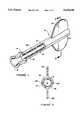
- FIG. 1is a perspective view, partly cut-away, or stent mounting device of this invention
- FIG. 2is a section view taken on line 2--2 in FIG. 1;
- FIG. 3is a perspective view of the sleeve portion of the stent mounting device on a supporting pin
- FIG. 4is a perspective view of the sleeve portion of the stent mounting device carrying a stent
- FIG. 5is a perspective view showing the assembly of the body portion of the stent mounting device
- FIG. 6is a perspective view showing the completed stent mounting device and removal of the support pin
- FIG. 7is a side elevation view of the stent mounting device on a catheter body shaft
- FIG. 8is a side elevation view of the stent mounting device positioned over a catheter balloon.
- FIG. 9is a side elevation view of the stent mounting device being axially split to release the balloon and stent assembly.
- the stent mounting device of this inventionprimarily comprises a body 10, a sleeve 12 having a knob 14 at one end and a stent 16.
- Body 10has an axial aperture 18 therethrough for receiving sleeve 12.
- Knob 14has any suitable shape to permit sleeve 12 to be easily pulled from axial aperture 18 during installation of a stent, as detailed below.
- the interior of knob 14preferably has a conical entrance section 15.
- Sleeve 12is preferably formed from a low friction material, such as fluorinated ethylene-propylene resins, polytetrafluoroethylene etc.
- Recesses 20are preferably provided in the wall of aperture 18 which are configured to receive stent 16 and help retain the stent in place.
- recesses 20would have a generally helical configuration to match the shape of the stent.
- Body 10may be formed from any suitable plastic material. Optimally, body 10 will be formed from a linearly oriented plastic material such as a mixture of polyurethane and polycarbonate which can be preferentially torn or split along lines parallel to the axis of aperture 18. Tabs 22 are provided at one end of body 10 to be grasped by a user's fingers and twisted or pulled apart to cause body 10 to split along grooves 24 on opposite sides of body 10.
- FIGS. 3-6The basic steps in manufacturing the stent mounting device are illustrated in FIGS. 3-6.
- a combination of sleeve 12 and knob 14are formed from a suitable low friction material by any suitable process, such as injection molding.
- An elongated pin 26 having a diameter substantially equal to the inside diameter of sleeve 12is inserted through sleeve 12 and knob 14 to support the sleeve.
- FIG. 4illustrates the placement of a stent 16 on sleeve 12.
- stent 16has a normal diameter slightly less than that of sleeve 12 and is expanded slightly as it is slid onto low friction sleeve 12. Stent 16 is thus held in place on sleeve 12 by spring forces.
- two halves of body 10formed by any suitable process, such as injection molding, are brought together, as indicated by arrow 28, over stent 16 and sleeve 12 and bonded together.
- Any suitable bonding methodmay be used, such as adhesive, ultrasonic or thermal bonding may be used.
- Recesses 20 in the surfaces of the two halves of aperture 18are configured to fit over stent 16.
- tubular portion of body 10it may be preferred to form the tubular portion of body 10 by a method such as extrusion that can produce a body having loser strength in an axial direction than in a transverse direction and having a low resistance to splitting in the axial direction.
- a methodsuch as extrusion that can produce a body having loser strength in an axial direction than in a transverse direction and having a low resistance to splitting in the axial direction.
- plasticsare polymers having long chain lengths and little cross linking.
- tabs 22may be bonded to the body in any suitable manner.
- pin 26is removed as indicated by arrow 30 and the stent mounting device is complete.
- These devicescan be assembled in a factory environment, maintained in a sterile condition and shipped to the user in sterile packaging.
- FIGS. 7-9illustrate the steps in using the stent mounting device to mount a stent onto the balloon of a balloon catheter.
- the deviceis placed on a catheter body shaft 32.
- Catheter 32carries a balloon 36.
- This catheter 32could have been used to dilate a lesion at the site where the stent is to be placed, then removed and balloon 36 rewrapped for use in placing the stent.
- Balloon 36is wrapped and is slightly larger in cross section than is aperture 18, so that the balloon is compressed somewhat as it enters the aperture, until the position shown in FIG. 8 is reached. If body 10 is formed from a transparent material, the relative positions of stent 16 and balloon 36 can be observed during placement.
- knob 14is pulled in the direction indicated by arrow 40 until sleeve 12 is pulled out from between balloon 36 and stent 16. Since sleeve 12 is formed from a low friction material, neither the balloon nor stent is disturbed by movement of sleeve 12.
- tabs 22are grasped by the user's fingers and twisted and/or pulled apart, as indicated by arrows 40 in FIG. 9, until body 10 splits along grooves 24.
- the stentis then held in place on the balloon by a combination of elastic contraction of the stent occurring when sleeve 12 is removed and the compression of balloon 36 that occurred when forced through conical entrance 15. While not necessary, ends of stent 16 could be lightly crimped by finger pressure, if desired.
Landscapes
- Health & Medical Sciences (AREA)
- Engineering & Computer Science (AREA)
- Biomedical Technology (AREA)
- Cardiology (AREA)
- Oral & Maxillofacial Surgery (AREA)
- Transplantation (AREA)
- Heart & Thoracic Surgery (AREA)
- Vascular Medicine (AREA)
- Life Sciences & Earth Sciences (AREA)
- Animal Behavior & Ethology (AREA)
- General Health & Medical Sciences (AREA)
- Public Health (AREA)
- Veterinary Medicine (AREA)
- Media Introduction/Drainage Providing Device (AREA)
Abstract
Description
This invention relates in general to intervascular stent implants for maintaining vascular patency in humans and animals and more particularly to a method and tool assembly for supporting a stent and for transferring the stent to a delivery system such as a balloon catheter.
Percutaneous transluminal coronary angioplasty (PTCA) is used to reduce arterial build-up of cholesterol fats or atherosclerotic plaque. Typically a guidewire is steered through the vascular system to the site of therapy. A guiding catheter, for example, can then be advanced over the guidewire and a balloon catheter advanced within the guiding catheter over the guidewire. The balloon at the distal end of the catheter is inflated causing the site of the stenosis to widen. The dilatation of the occlusion, however, can form flaps, fissures and dissections which threaten re-closure of the dilated vessel or even perforations in the vessel wall. Implantation of a metal stent can provide support for such flaps and dissections and thereby prevent reclosure of the vessel or provide a patch repair for a perforated vessel wall until corrective surgery can be performed. Reducing the possibility of restenosis after angioplasty reduces the likelihood that a secondary angioplasty procedure or a surgical bypass operation will be necessary.
An implanted prosthesis such as a stent can preclude additional procedures and maintain vascular patency by mechanically supporting dilated vessels to prevent vessel collapse. Stents can also be used to repair aneurysms, to support artificial vessels as liners of vessels or to repair dissections. Stents are suited to the treatment of any body lumen, including the vas deferens, ducts of the gallbladder, prostate gland, trachea, bronchus and liver. The body lumens range in size from the small coronary vessels to the 30 mm aortic vessel. The invention applies to acute and chronic closure or reclosure of body lumens.
A stent typically is a cylindrically shaped device formed from wires or a slotted tube and intended to act as a permanent prosthesis. A stent is deployed in a body lumen from a radially compressed configuration into a radially expanded configuration which allows it to contact and support a body lumen. The stent can be made to be radially self-expanding or expandable by the use of an expansion device. The self expanding stent is made from a resilient springy material while the device expandable stent is made from a material which is plastically deformable. A plastically deformable stent can be implanted during a single angioplasty procedure by using a balloon catheter bearing a stent which has been crimped onto the balloon. Stents radially expand as the balloon is inflated, forcing the stent into contact with the body lumen thereby forming a supporting relationship with the vessel walls. Deployment is effected after the stent has been introduced percutaneously, transported transluminally and positioned at a desired location by means of the balloon catheter.
The stainless-steel or tantalum mesh stent that props open blocked coronary arteries, keeps them from reclosing after balloon angioplasty. A balloon of appropriate size and pressure is first used to open the lesion. The process is repeated with a stent crimped on a balloon. The stent is deployed when the balloon is inflated. The stent remains as a permanent scaffold after the balloon is withdrawn.
A number of different stent structures and placement instruments have been developed. For example, Wall in U.S. Pat. No. 5,266,073 describes a rolled tubular stent carried at the end of a tubular catheter with a second catheter threaded therethrough to carry a balloon. The assembly is inserted into an artery until the stent is at the proper location, then the balloon catheter is positioned within the stent and expanded to expand, unroll and lock the stent. This arrangement usually requires an undesirably large diameter catheter for carrying the stent and includes a complex and possibly unreliable locking method for holding the stent in the expanded position. Also, non-uniform stent expansion may occur, since the expanding balloon cannot directly contact the portion of the stent that overlaps its carrier catheter.
Other stent delivery systems have a self-expanding stent compressed in a tube, such as that described by Burton et al. in U.S. Pat. No. 5,026,377. The tube is inserted until the stent is in the desired location and the stent is forced from the tube and expands into contact with the vessel wall. A balloon catheter may be inserted and expanded to further expand the stent. Problems may arise with maintaining the partially expanded stent in position and preventing pushing the stent out of position during insertion of the balloon catheter.
Others have used a rolled tubular stent placed around a balloon catheter and covered by a tubular sheath connected to a guidewire extending through the catheter, such as is described by Lau et al. in U.S. Pat. No. 5,158,548. The assembly is inserted in to a desired location in a body lumen, the sheath is moved longitudinally by the guidewire away from the stent and the balloon is expanded to expand the stent. This requires a complex tubular catheter, sheath and stent assembly.
Balloon catheters are available with a stent preloaded around the balloon. This requires a second balloon catheter to be used to dilate the lesion enough to allow the stent to enter. Subsequently, the catheter bearing the stent is introduced and the stent emplaced. This requires the use of two expensive catheters to complete placement of the stent and two catheterization.
Loose stents are available which users simply slip over a balloon catheter and crimp against the catheter balloon with the fingers. While this arrangement is simple and quick, the stent may be damaged during storage and handling prior to use, while it is being placed over the catheter balloon or during the crimping step. Damaged stents cannot be used. If damage to the stent is not noticed, the stent may not perform as intended in use. Further, depending on the type of delivery system, fitting the stent over the delivery end without damage is sometimes difficult.
Excellent methods and apparatus for mounting stents on catheter balloons and the like are described by Rupp et al. in U.S. patent application Ser. No. 08/576,720, filed Dec. 21, 1995, now pending and assigned to the assignee of this application. While the methods and apparatus described in that application provide excellent results, I have found that in some instances a disposable mounting device is preferable.
Thus, there is a continuing need for improved devices and methods for mounting a stent onto a delivery system such as a balloon catheter that are simpler, less expensive, more convenient, more reliable, avoid damage to the stent and include a sterile, disposable, mounting device to avoid contact between a sterile stent and catheter and a non-sterile surface.
The above-noted problems, and others, are overcome in accordance with this invention by a stent mounting device comprising an elongated body formed from two, usually identical, halves bonded together. The body has an axial aperture in which a stent is retained. A low friction sleeve member is inserted into the axial aperture for receiving a delivery system, such as a balloon catheter. In addition, the invention includes a method of making such a device and a method of mounting a stent on a delivery system with the device.
The stent mounting device basically consists of two body halves each having a longitudinal recess on mating surfaces. The mating surfaces are bonded together with a stent in one recess. The stent is held in place in the axial aperture formed when the two recesses abut. Preferably, shallow channels are formed in the wall of the axial aperture to fit the stent configuration and help hold the stent in place. For example, with Wiktor stents, a shallow, relatively wide, helical channel would be appropriate.
In order to place a stent into the aperture, the stent is mounted on a sleeve that is placed in the recess in one body half before the body halves are bonded together. The sleeve is formed from a thin, low friction material such as tetrafluroethylene and has an outside diameter corresponding substantially to the inside diameter of the body axial aperture. The sleeve has a handle or knob formed on one end abutting an end of the body aperture for removal of the sleeve. The stent is placed over the sleeve and a pin having a diameter substantially the same as the sleeve internal diameter is inserted into the pin to support the sleeve. Preferably the stent diameter is slightly less than the outside diameter of the sleeve so as to be held in place by stent resiliency. The assembly of pin, sleeve and stent is placed between the body halves with the stent aligned with the aperture internal channel and the knob just outside an end of the axial aperture.
The body halves are bonded together in any suitable manner, such as adhesive, ultrasonic, or thermal bonding. Once bonding is complete, the pin is slipped out of the sleeve.
A delivery system, such as a catheter carrying a wrapped balloon, is slipped into the sleeve and aligned with the stent. Preferably, the body and sleeve are formed from a transparent material so that the position of the delivery system in the device can be observed. The delivery system is inserted through a hole in the sleeve knob that is coaxial with the sleeve. Since the delivery system, (e.g. a balloon catheter) is preferably slightly compressible and slightly greater in diameter that the inside sleeve diameter, the hole in the sleeve knob is preferably conical to compress the delivery system during insertion.
Once insertion is complete, the sleeve is pulled from between the stent and the delivery system. The stent contracts slightly and the delivery system expands slightly, so that the two are held tightly together.
A V-shaped groove is preferably provided along two opposite sides of the body and two outwardly extending tabs are formed between the grooves so that the tabs can be grasped and pulled apart to split the body apart to release the stent mounted on the delivery system. Preferably, the body is formed from a longitudinally oriented plastic material that preferentially splits in the longitudinal direction. Typical such materials include mixtures of polyurethane and polycarbonate. The delivery system with mounted stent is now ready for use.
In conventional practice, to repair a lesion in a bodily vessel, generally one balloon catheter is inserted and expanded to dilate the lesion. Then a second balloon catheter carrying a stent is inserted and expanded to place the stent at the location of the lesion. A single catheter can perform both functions, using the device and method of this invention. The catheter is inserted and the balloon is expanded to dilate the lesion. Then the balloon is deflated, the catheter removed and the balloon rewrapped. The device of this invention is then fitted over the balloon and the stent is transferred to the balloon as described above. The catheter is reinserted so that the balloon is again at the original lesion site. The balloon is expanded to expand and place the stent. Finally, the balloon is deflated and the catheter is removed, leaving the stent in place.
It is, therefore, an object of this invention to provide an improved device and method for placing stents onto any of a variety of delivery systems. Another object of the invention is to provide a stent mounting device that permits use of a single catheter for dilating a lesion and for placing a stent at the lesion site. A further object is to provide a device for mechanically applying a stent to a delivery system which does not require manual finger crimping of the stent. Yet another object is to provide a disposable device that can be preloaded with a stent for applying stents to balloon catheter. Other objects and advantages of the stent installation device and method of this invention will become apparent upon reading the following description of preferred embodiments.
Details of the invention, and of preferred embodiments thereof, will be further understood upon reference to the drawing, wherein:
FIG. 1 is a perspective view, partly cut-away, or stent mounting device of this invention;
FIG. 2 is a section view taken online 2--2 in FIG. 1;
FIG. 3 is a perspective view of the sleeve portion of the stent mounting device on a supporting pin;
FIG. 4 is a perspective view of the sleeve portion of the stent mounting device carrying a stent;
FIG. 5 is a perspective view showing the assembly of the body portion of the stent mounting device;
FIG. 6 is a perspective view showing the completed stent mounting device and removal of the support pin;
FIG. 7 is a side elevation view of the stent mounting device on a catheter body shaft;
FIG. 8 is a side elevation view of the stent mounting device positioned over a catheter balloon; and
FIG. 9 is a side elevation view of the stent mounting device being axially split to release the balloon and stent assembly.
As seen in FIGS. 1 and 2, the stent mounting device of this invention primarily comprises abody 10, asleeve 12 having aknob 14 at one end and astent 16.Body 10 has anaxial aperture 18 therethrough for receivingsleeve 12.Knob 14 has any suitable shape to permitsleeve 12 to be easily pulled fromaxial aperture 18 during installation of a stent, as detailed below. The interior ofknob 14 preferably has aconical entrance section 15.Sleeve 12 is preferably formed from a low friction material, such as fluorinated ethylene-propylene resins, polytetrafluoroethylene etc.
The basic steps in manufacturing the stent mounting device are illustrated in FIGS. 3-6.
Initially, as seen in FIG. 3, a combination ofsleeve 12 andknob 14 are formed from a suitable low friction material by any suitable process, such as injection molding. Anelongated pin 26 having a diameter substantially equal to the inside diameter ofsleeve 12 is inserted throughsleeve 12 andknob 14 to support the sleeve.
FIG. 4 illustrates the placement of astent 16 onsleeve 12. Preferably,stent 16 has a normal diameter slightly less than that ofsleeve 12 and is expanded slightly as it is slid ontolow friction sleeve 12.Stent 16 is thus held in place onsleeve 12 by spring forces.
Next, as seen in FIG. 5, two halves ofbody 10, formed by any suitable process, such as injection molding, are brought together, as indicated byarrow 28, overstent 16 andsleeve 12 and bonded together. Any suitable bonding method may be used, such as adhesive, ultrasonic or thermal bonding may be used.Recesses 20 in the surfaces of the two halves ofaperture 18 are configured to fit overstent 16.
In some cases, it may be preferred to form the tubular portion ofbody 10 by a method such as extrusion that can produce a body having loser strength in an axial direction than in a transverse direction and having a low resistance to splitting in the axial direction. Typically, such plastics are polymers having long chain lengths and little cross linking. Then,tabs 22 may be bonded to the body in any suitable manner.
When bonding of the body and tab halves together is complete,pin 26 is removed as indicated byarrow 30 and the stent mounting device is complete. These devices can be assembled in a factory environment, maintained in a sterile condition and shipped to the user in sterile packaging.
FIGS. 7-9 illustrate the steps in using the stent mounting device to mount a stent onto the balloon of a balloon catheter.
Initially, as seen in FIG. 7, the device is placed on acatheter body shaft 32.Catheter 32 carries aballoon 36. Thiscatheter 32 could have been used to dilate a lesion at the site where the stent is to be placed, then removed andballoon 36 rewrapped for use in placing the stent.
As the device is moved alongcatheter 32, in the direction indicated byarrow 38 untilballoon 36 begins to enter the conical entrance (not seen in FIGS. 7-9).Balloon 36 is wrapped and is slightly larger in cross section than isaperture 18, so that the balloon is compressed somewhat as it enters the aperture, until the position shown in FIG. 8 is reached. Ifbody 10 is formed from a transparent material, the relative positions ofstent 16 andballoon 36 can be observed during placement.
Onceballoon 36 is properly placed,knob 14 is pulled in the direction indicated byarrow 40 untilsleeve 12 is pulled out from betweenballoon 36 andstent 16. Sincesleeve 12 is formed from a low friction material, neither the balloon nor stent is disturbed by movement ofsleeve 12.
Finally,tabs 22 are grasped by the user's fingers and twisted and/or pulled apart, as indicated byarrows 40 in FIG. 9, untilbody 10 splits alonggrooves 24. The stent is then held in place on the balloon by a combination of elastic contraction of the stent occurring whensleeve 12 is removed and the compression ofballoon 36 that occurred when forced throughconical entrance 15. While not necessary, ends ofstent 16 could be lightly crimped by finger pressure, if desired.
While certain specific relationships, materials and other parameters have been detailed in the above description of preferred embodiments, those can be varied, where suitable, with similar results. Other applications, variations and ramifications of the present invention will occur to those skilled in the art upon reading the present disclosure. Those are intended to be included within the scope of this invention as defined in the appended claims.
Claims (21)
1. A device for mounting a stent on a delivery system which comprises:
an elongated body having an axial aperture therethrough;
a stent in said axial aperture in engagement with a wail of said aperture;
a sleeve of low friction material in said stent;
tubular entrance means having a proximal end secured to said sleeve and extending beyond an end of said axial aperture for axially moving said sleeve from said axial aperture; and
means for permitting said body to be split along said axial aperture comprising grooves running substantially parallel to said axial aperture in an exterior surface of said body to remove said body from said stent.
2. The device according to claim 1 wherein said tubular entrance tapers from a wider distal end to a narrower proximal end for receiving an end of a delivery means and guiding said delivery means into said axial aperture.
3. The device according to claim 1 wherein said delivery means is a balloon catheter.
4. The device according to claim 1 wherein said body is formed from a material having less resistance to splitting in a direction substantially parallel to said axial aperture than in a direction transverse thereto.
5. The device according to claim 1 further including tabs secured to said body for gripping by a user's fingers in splitting said body.
6. The device according to claim 1 further including recesses in an interior wall of said aperture, said recesses configured to receive said stent therein.
7. The device according to claim 1 wherein said sleeve is formed from a low friction material selected from the group consisting of fluorinated ethylene-propylene resins, polytetrafluoroethylene and mixtures and copolymers thereof.
8. A device for mounting a stent on a balloon catheter which comprises:
elongated body means having an axial aperture therethrough for receiving a stent;
a stent within said elongated aperture in engagement with a wall of said axial aperture;
retaining means in said axial aperture for restraining said stent against axial movement relative to said axial aperture;
tubular sleeve means formed from low friction material within and in pressure contact with said stent;
entrance means secured to said sleeve for guiding a balloon catheter into said axial aperture and for manually withdrawing said sleeve from said axial aperture; and
means for splitting said body along said axial aperture comprising grooves running substantially parallel to said axial aperture in an exterior surface of said body and tabs secured to said body for gripping by a user's fingers in splitting said body.
9. The device according to claim 8 wherein said tubular entrance tapers from a wider distal end to a narrower proximal end for receiving an end of a delivery means and guiding said delivery means into said axial aperture.
10. The device according to claim 8 wherein said body is formed from a material having less resistance to splitting in a direction substantially parallel to said axial aperture than in a direction transverse thereto.
11. The device according to claim 8 further including recesses in an interior wall of said aperture, said recesses configured to receive said stent therein.
12. The device according to claim 8 wherein said sleeve is formed from a low friction material selected from the group consisting of fluorinated ethylene-propylene resins, polytetrafluoroethylene and mixtures and copolymers thereof.
13. A method of making an assembly for mounting a stent on a delivery system which comprises the steps of:
forming an elongated tubular sleeve having a handle portion at one end;
placing a stent over said sleeve;
forming two halves of a body having axial depressions therealong for cooperatively forming an axial aperture and having manually separable weakened lines along said body;
placing said sleeve on one of said halves; and
bonding said halves together with said stent in said central aperture.
14. The method of making an assembly according to claim 13 including the further steps of inserting a pin having a cross section substantially equal to sleeve interior cross section into said sleeve prior to placing said stent over said sleeve and of removing said pin after bonding said halves together.
15. The method of making an assembly according to claim 14 wherein said tubular sleeve is formed with an outside diameter greater than stent inside diameter so that said stent is in tension over said sleeve.
16. The method of making an assembly according to claim 13 further including forming an outwardly extending tab on each said body half adjacent to an end of said body half.
17. The method of making an assembly according to claim 13 wherein said sleeve is formed from a low friction material selected from the group consisting of fluorinated ethylene-propylene resins, polytetrafluoroethylene and mixtures and copolymers thereof.
18. A method of mounting a stent on a delivery system which comprises the steps of:
providing a body having an axial aperture therethrough, a sleeve in said aperture and a stent between the outer surface of said sleeve and said aperture, said stent in tension over said sleeve;
inserting a delivery system into said sleeve, said delivery system's balloon in compression is said sleeve;
removing said sleeve from said axial aperture, leaving an assembly of said stent surrounding and in pressure contact with said delivery system; and
tearing said body into two portions along lines that intersect the length of said aperture to release said assembly.
19. The method of mounting a stent on a delivery system according to claim 18 wherein said body has grooves on an external surface substantially parallel with said axial aperture and tabs extending from said body adjacent to one end of said body and said tearing is accomplished by pulling said tabs apart to split said body along said grooves.
20. The method of mounting a stent on a delivery system according to claim 18 wherein said sleeve includes a handle portion extending beyond said axial aperture having a generally conical central opening communicating with said sleeve, said delivery system's balloon is inserted through said central opening and compressed during entry into said sleeve and said sleeve is removed from said axial aperture by pulling on said handle.
21. The method of mounting a stent on a delivery system according to claim 18 wherein said sleeve is formed from a low friction material selected from the group consisting of fluorinated ethylene-propylene resins, polytetrafluoroethylene and mixtures and copolymers thereof.
Priority Applications (1)
| Application Number | Priority Date | Filing Date | Title |
|---|---|---|---|
| US08/631,750US5630830A (en) | 1996-04-10 | 1996-04-10 | Device and method for mounting stents on delivery systems |
Applications Claiming Priority (1)
| Application Number | Priority Date | Filing Date | Title |
|---|---|---|---|
| US08/631,750US5630830A (en) | 1996-04-10 | 1996-04-10 | Device and method for mounting stents on delivery systems |
Publications (1)
| Publication Number | Publication Date |
|---|---|
| US5630830Atrue US5630830A (en) | 1997-05-20 |
Family
ID=24532582
Family Applications (1)
| Application Number | Title | Priority Date | Filing Date |
|---|---|---|---|
| US08/631,750Expired - Fee RelatedUS5630830A (en) | 1996-04-10 | 1996-04-10 | Device and method for mounting stents on delivery systems |
Country Status (1)
| Country | Link |
|---|---|
| US (1) | US5630830A (en) |
Cited By (93)
| Publication number | Priority date | Publication date | Assignee | Title |
|---|---|---|---|---|
| US5725519A (en)* | 1996-09-30 | 1998-03-10 | Medtronic Instent Israel Ltd. | Stent loading device for a balloon catheter |
| US5738674A (en)* | 1993-05-24 | 1998-04-14 | Advanced Cardiovascular Systems, Inc. | Stent loading mechanism |
| US5810838A (en)* | 1997-03-13 | 1998-09-22 | Solar; Ronald J. | Hydraulic method and apparatus for uniform radial compression and catheter mounting of radially expandable intraluminal stents and stented grafts |
| US5810873A (en)* | 1997-07-15 | 1998-09-22 | Advanced Cardiovascular Systems, Inc. | Stent crimping tool and method of use |
| US5836952A (en)* | 1996-08-21 | 1998-11-17 | Cordis Corporation | Hand-held stent crimper |
| US5893852A (en)* | 1998-04-28 | 1999-04-13 | Advanced Cardiovascular Systems, Inc. | Stent crimping tool and method of use |
| EP0916318A1 (en)* | 1997-10-16 | 1999-05-19 | SciMed Life Systems, Inc. | Stent crimper |
| US5911452A (en)* | 1997-02-04 | 1999-06-15 | Advanced Cardiovascular Systems, Inc. | Apparatus and method for mounting a stent onto a catheter |
| EP0904746A3 (en)* | 1997-09-30 | 1999-07-07 | Cordis Corporation | A tool for inserting a stent into a catheter |
| US5920975A (en)* | 1997-11-03 | 1999-07-13 | Advanced Cardiovascular Systems, Inc. | Stent crimping tool and method of use |
| US5928258A (en)* | 1997-09-26 | 1999-07-27 | Corvita Corporation | Method and apparatus for loading a stent or stent-graft into a delivery sheath |
| US5931851A (en)* | 1998-04-21 | 1999-08-03 | Advanced Cardiovascular Systems, Inc. | Method and apparatus for rubber-tube crimping tool with premount stent |
| US5951540A (en)* | 1998-10-22 | 1999-09-14 | Medtronic, Inc. | Device and method for mounting stents |
| US5972016A (en)* | 1997-04-22 | 1999-10-26 | Advanced Cardiovascular Systems, Inc. | Stent crimping device and method of use |
| US5971992A (en)* | 1997-03-13 | 1999-10-26 | Solar; Ronald J. | Hydraulic method and apparatus for uniform radial compression and catheter mounting of radially expandable intraluminal stents and stented grafts |
| US5974652A (en)* | 1998-05-05 | 1999-11-02 | Advanced Cardiovascular Systems, Inc. | Method and apparatus for uniformly crimping a stent onto a catheter |
| WO1999062428A1 (en)* | 1998-06-04 | 1999-12-09 | Scimed Life Systems, Inc. | Stent loading tool |
| US6009614A (en)* | 1998-04-21 | 2000-01-04 | Advanced Cardiovascular Systems, Inc. | Stent crimping tool and method of use |
| US6018857A (en)* | 1997-10-30 | 2000-02-01 | Ave Connaught | Device and method for mounting a stent onto a balloon catheter |
| US6024737A (en)* | 1998-02-25 | 2000-02-15 | Advanced Cardiovascular Systems, Inc. | Stent crimping device |
| US6068635A (en)* | 1998-03-04 | 2000-05-30 | Schneider (Usa) Inc | Device for introducing an endoprosthesis into a catheter shaft |
| US6082990A (en)* | 1998-02-17 | 2000-07-04 | Advanced Cardiovascular Systems, Inc. | Stent crimping tool |
| US6090035A (en)* | 1999-03-19 | 2000-07-18 | Isostent, Inc. | Stent loading assembly for a self-expanding stent |
| US6096027A (en)* | 1998-09-30 | 2000-08-01 | Impra, Inc., A Subsidiary Of C.R. Bard, Inc. | Bag enclosed stent loading apparatus |
| US6125523A (en)* | 1998-11-20 | 2000-10-03 | Advanced Cardiovascular Systems, Inc. | Stent crimping tool and method of use |
| US6132458A (en)* | 1998-05-15 | 2000-10-17 | American Medical Systems, Inc. | Method and device for loading a stent |
| US6141855A (en)* | 1998-04-28 | 2000-11-07 | Advanced Cardiovascular Systems, Inc. | Stent crimping tool and method of use |
| US6162237A (en)* | 1999-04-19 | 2000-12-19 | Chan; Winston Kam Yew | Temporary intravascular stent for use in retrohepatic IVC or hepatic vein injury |
| US6167605B1 (en) | 1997-09-12 | 2001-01-02 | Advanced Cardiovascular Systems, Inc. | Collet type crimping tool |
| US6203551B1 (en)* | 1999-10-04 | 2001-03-20 | Advanced Cardiovascular Systems, Inc. | Chamber for applying therapeutic substances to an implant device |
| US6352547B1 (en) | 1999-09-22 | 2002-03-05 | Scimed Life Systems, Inc. | Stent crimping system |
| US6360577B2 (en) | 1999-09-22 | 2002-03-26 | Scimed Life Systems, Inc. | Apparatus for contracting, or crimping stents |
| US6364870B1 (en) | 1998-12-22 | 2002-04-02 | Medinol Ltd. | Apparatus and method for securing a stent on a balloon |
| US6387117B1 (en) | 1999-09-22 | 2002-05-14 | Scimed Life Systems, Inc. | Stent crimping system |
| US20020138129A1 (en)* | 1999-01-22 | 2002-09-26 | Armstrong Joseph R. | Method of producing low profile stent and graft combination |
| US20020163104A1 (en)* | 2001-03-26 | 2002-11-07 | Tom Motsenbocker | Balloon folding technology |
| US6481262B2 (en) | 1999-12-30 | 2002-11-19 | Advanced Cardiovascular Systems, Inc. | Stent crimping tool |
| US6510722B1 (en) | 2000-05-10 | 2003-01-28 | Advanced Cardiovascular Systems, Inc. | Stent crimping tool for producing a grooved crimp |
| US6533806B1 (en) | 1999-10-01 | 2003-03-18 | Scimed Life Systems, Inc. | Balloon yielded delivery system and endovascular graft design for easy deployment |
| US6568235B1 (en) | 2000-08-10 | 2003-05-27 | Advanced Cardiovascular Systems, Inc. | Assembly for crimping an intraluminal device or measuring the radial strength of the intraluminal device and method of use |
| US20030139795A1 (en)* | 2002-01-23 | 2003-07-24 | Scimed Life Systems, Inc. | Stent delivery system loading tool |
| US6629350B2 (en) | 2000-06-08 | 2003-10-07 | Tom Motsenbocker | Stent crimping apparatus and method |
| US6640412B2 (en) | 2001-04-26 | 2003-11-04 | Endovascular Technologies, Inc. | Method for loading a stent using a collapsing machine |
| US20040010265A1 (en)* | 2002-05-31 | 2004-01-15 | Wilson-Cook Medical, Inc. | Stent introducer apparatus |
| US6689123B2 (en) | 1998-12-22 | 2004-02-10 | Medinol Ltd. | Apparatus and method for securing a stent on a balloon |
| US6739033B2 (en) | 2001-03-29 | 2004-05-25 | Scimed Life Systems, Inc. | Thermal regulation of a coated work-piece during the reconfiguration of the coated work-piece |
| US20040123437A1 (en)* | 2002-12-26 | 2004-07-01 | Arkady Kokish | Assembly for crimping an intraluminal device and method of use |
| US6769161B2 (en) | 1997-10-16 | 2004-08-03 | Scimed Life Systems, Inc. | Radial stent crimper |
| US20040155053A1 (en)* | 2003-02-10 | 2004-08-12 | Sanchez Khiro M. | Stent package |
| US6840081B2 (en) | 2000-08-10 | 2005-01-11 | Advanced Cardiovascular Systems, Inc. | Assembly for crimping an intraluminal device or measuring the radial strength of the intraluminal device and method of use |
| US20050021122A1 (en)* | 2002-10-26 | 2005-01-27 | Peter Eisenkolb | Device for compressing tubular endoprostheses and for inserting a compressed endoprosthesis into an application tube |
| WO2005065764A1 (en)* | 2003-12-22 | 2005-07-21 | Boston Scientific Limited | Balloon catheter retrieval device |
| US20050234537A1 (en)* | 2004-04-16 | 2005-10-20 | Scimed Life Systems, Inc. | Stent crimper |
| US20050229670A1 (en)* | 2004-04-16 | 2005-10-20 | Scimed Life Systems, Inc. | Stent crimper |
| US7112055B1 (en) | 2002-07-02 | 2006-09-26 | Endovascular Technologies, Inc. | Nitinol frame heating and setting mandrel |
| US20060229712A1 (en)* | 2005-04-12 | 2006-10-12 | Advanced Cardiovascular Systems, Inc. | Method of stent mounting to form a balloon catheter having improved retention of a drug delivery stent |
| US20070288034A1 (en)* | 2006-06-07 | 2007-12-13 | Maccollum Michael W | Stent Expanding device |
| US20070288080A1 (en)* | 2006-06-07 | 2007-12-13 | Maccollum Michael W | Stent expanding device |
| US20080001328A1 (en)* | 2006-06-30 | 2008-01-03 | Kent Darrin J | Stent retention mold and method |
| US20080127707A1 (en)* | 2006-11-30 | 2008-06-05 | Abbott Laboratories | Stent crimping assembly and method |
| US7389670B1 (en) | 2004-07-26 | 2008-06-24 | Abbott Laboratories | Stent crimping system |
| US20080307668A1 (en)* | 2007-06-15 | 2008-12-18 | Sidney Watterodt | Methods and devices for drying coated stents |
| US20080312728A1 (en)* | 2007-06-15 | 2008-12-18 | Sang Joon Park | Method and device for aligning a stent with a stent support |
| US20090105806A1 (en)* | 2007-10-23 | 2009-04-23 | Endologix, Inc | Stent |
| WO2010014779A1 (en)* | 2008-08-01 | 2010-02-04 | Boston Scientific Scimed, Inc. | Bifurcation catheter assembly side catheter branch construction and methods |
| US20100057185A1 (en)* | 2008-09-04 | 2010-03-04 | Cook Incorporated | Sliding Split-Sleeve Implant Compressor |
| US7708548B2 (en)* | 2005-04-12 | 2010-05-04 | Advanced Cardiovascular Systems, Inc. | Molds for fabricating stents with profiles for gripping a balloon catheter |
| US20100204773A1 (en)* | 2006-03-06 | 2010-08-12 | Elmaleh David R | Delivery system for intravascular device with netting |
| US7846171B2 (en) | 2004-05-27 | 2010-12-07 | C.R. Bard, Inc. | Method and apparatus for delivering a prosthetic fabric into a patient |
| US20110100086A1 (en)* | 2004-02-26 | 2011-05-05 | Boston Scientific Scimed, Inc. | Crimper |
| US8003157B2 (en) | 2007-06-15 | 2011-08-23 | Abbott Cardiovascular Systems Inc. | System and method for coating a stent |
| US8034100B2 (en) | 1999-03-11 | 2011-10-11 | Endologix, Inc. | Graft deployment system |
| US8118856B2 (en) | 2009-07-27 | 2012-02-21 | Endologix, Inc. | Stent graft |
| US8167925B2 (en) | 1999-03-11 | 2012-05-01 | Endologix, Inc. | Single puncture bifurcation graft deployment system |
| US8216295B2 (en) | 2008-07-01 | 2012-07-10 | Endologix, Inc. | Catheter system and methods of using same |
| US8221112B2 (en) | 2005-04-12 | 2012-07-17 | Abbott Cardiovascular Systems, Inc. | Method for retaining a vascular stent on a catheter |
| US8236040B2 (en) | 2008-04-11 | 2012-08-07 | Endologix, Inc. | Bifurcated graft deployment systems and methods |
| US8491646B2 (en) | 2009-07-15 | 2013-07-23 | Endologix, Inc. | Stent graft |
| US20130218139A1 (en)* | 2012-02-16 | 2013-08-22 | Biotronik Ag | Crimping device and method for mounting a vascular stent |
| US8523931B2 (en) | 2007-01-12 | 2013-09-03 | Endologix, Inc. | Dual concentric guidewire and methods of bifurcated graft deployment |
| CH706684A1 (en)* | 2012-06-28 | 2013-12-31 | Qvanteq Ag | Packaging and transfer system for implant application. |
| US8808350B2 (en) | 2011-03-01 | 2014-08-19 | Endologix, Inc. | Catheter system and methods of using same |
| US8945202B2 (en) | 2009-04-28 | 2015-02-03 | Endologix, Inc. | Fenestrated prosthesis |
| US9393100B2 (en) | 2010-11-17 | 2016-07-19 | Endologix, Inc. | Devices and methods to treat vascular dissections |
| US9433991B2 (en) | 2011-12-21 | 2016-09-06 | Edwards Lifesciences Corporation | Apparatus and method for stent shaping |
| US9533120B1 (en) | 2011-12-02 | 2017-01-03 | Greatbatch Ltd. | Transseptal needle assembly |
| US9579103B2 (en) | 2009-05-01 | 2017-02-28 | Endologix, Inc. | Percutaneous method and device to treat dissections |
| US9974672B2 (en) | 2012-10-15 | 2018-05-22 | David R Elmaleh | Material structures for intravascular device |
| US10245166B2 (en) | 2008-02-22 | 2019-04-02 | Endologix, Inc. | Apparatus and method of placement of a graft or graft system |
| US10772717B2 (en) | 2009-05-01 | 2020-09-15 | Endologix, Inc. | Percutaneous method and device to treat dissections |
| US11129737B2 (en) | 2015-06-30 | 2021-09-28 | Endologix Llc | Locking assembly for coupling guidewire to delivery system |
| US11406518B2 (en) | 2010-11-02 | 2022-08-09 | Endologix Llc | Apparatus and method of placement of a graft or graft system |
| USD1046133S1 (en)* | 2020-03-04 | 2024-10-08 | Olympus Corporation | Handle of stent placement device |
Citations (24)
| Publication number | Priority date | Publication date | Assignee | Title |
|---|---|---|---|---|
| US3382872A (en)* | 1965-06-07 | 1968-05-14 | Melvin L. Rubin | Venous catheter and needle |
| US3677244A (en)* | 1969-08-04 | 1972-07-18 | Extracorporeal Med Spec | Removable catheter needle |
| US3877429A (en)* | 1973-11-30 | 1975-04-15 | David L Rasumoff | Catheter placement device |
| US4166469A (en)* | 1977-12-13 | 1979-09-04 | Littleford Philip O | Apparatus and method for inserting an electrode |
| US4243050A (en)* | 1977-12-13 | 1981-01-06 | Littleford Philip O | Method for inserting pacemaker electrodes and the like |
| US4345606A (en)* | 1977-12-13 | 1982-08-24 | Littleford Philip O | Split sleeve introducers for pacemaker electrodes and the like |
| US4830003A (en)* | 1988-06-17 | 1989-05-16 | Wolff Rodney G | Compressive stent and delivery system |
| US4913141A (en)* | 1988-10-25 | 1990-04-03 | Cordis Corporation | Apparatus and method for placement of a stent within a subject vessel |
| US5026377A (en)* | 1989-07-13 | 1991-06-25 | American Medical Systems, Inc. | Stent placement instrument and method |
| US5108416A (en)* | 1990-02-13 | 1992-04-28 | C. R. Bard, Inc. | Stent introducer system |
| US5158548A (en)* | 1990-04-25 | 1992-10-27 | Advanced Cardiovascular Systems, Inc. | Method and system for stent delivery |
| US5190058A (en)* | 1991-05-22 | 1993-03-02 | Medtronic, Inc. | Method of using a temporary stent catheter |
| US5192297A (en)* | 1991-12-31 | 1993-03-09 | Medtronic, Inc. | Apparatus and method for placement and implantation of a stent |
| US5201757A (en)* | 1992-04-03 | 1993-04-13 | Schneider (Usa) Inc. | Medial region deployment of radially self-expanding stents |
| US5226889A (en)* | 1990-07-30 | 1993-07-13 | Imad Sheiban | Double balloon catheter for stent implantation |
| US5242399A (en)* | 1990-04-25 | 1993-09-07 | Advanced Cardiovascular Systems, Inc. | Method and system for stent delivery |
| US5266073A (en)* | 1987-12-08 | 1993-11-30 | Wall W Henry | Angioplasty stent |
| US5306294A (en)* | 1992-08-05 | 1994-04-26 | Ultrasonic Sensing And Monitoring Systems, Inc. | Stent construction of rolled configuration |
| US5338296A (en)* | 1993-01-06 | 1994-08-16 | Ethicon, Inc. | Catheter and sheath assembly |
| US5344426A (en)* | 1990-04-25 | 1994-09-06 | Advanced Cardiovascular Systems, Inc. | Method and system for stent delivery |
| US5360401A (en)* | 1993-02-18 | 1994-11-01 | Advanced Cardiovascular Systems, Inc. | Catheter for stent delivery |
| US5368566A (en)* | 1992-04-29 | 1994-11-29 | Cardiovascular Dynamics, Inc. | Delivery and temporary stent catheter having a reinforced perfusion lumen |
| US5387235A (en)* | 1991-10-25 | 1995-02-07 | Cook Incorporated | Expandable transluminal graft prosthesis for repair of aneurysm |
| US5391172A (en)* | 1993-05-24 | 1995-02-21 | Advanced Cardiovascular Systems, Inc. | Stent delivery system with coaxial catheter handle |
- 1996
- 1996-04-10USUS08/631,750patent/US5630830A/ennot_activeExpired - Fee Related
Patent Citations (24)
| Publication number | Priority date | Publication date | Assignee | Title |
|---|---|---|---|---|
| US3382872A (en)* | 1965-06-07 | 1968-05-14 | Melvin L. Rubin | Venous catheter and needle |
| US3677244A (en)* | 1969-08-04 | 1972-07-18 | Extracorporeal Med Spec | Removable catheter needle |
| US3877429A (en)* | 1973-11-30 | 1975-04-15 | David L Rasumoff | Catheter placement device |
| US4243050A (en)* | 1977-12-13 | 1981-01-06 | Littleford Philip O | Method for inserting pacemaker electrodes and the like |
| US4166469A (en)* | 1977-12-13 | 1979-09-04 | Littleford Philip O | Apparatus and method for inserting an electrode |
| US4345606A (en)* | 1977-12-13 | 1982-08-24 | Littleford Philip O | Split sleeve introducers for pacemaker electrodes and the like |
| US5266073A (en)* | 1987-12-08 | 1993-11-30 | Wall W Henry | Angioplasty stent |
| US4830003A (en)* | 1988-06-17 | 1989-05-16 | Wolff Rodney G | Compressive stent and delivery system |
| US4913141A (en)* | 1988-10-25 | 1990-04-03 | Cordis Corporation | Apparatus and method for placement of a stent within a subject vessel |
| US5026377A (en)* | 1989-07-13 | 1991-06-25 | American Medical Systems, Inc. | Stent placement instrument and method |
| US5108416A (en)* | 1990-02-13 | 1992-04-28 | C. R. Bard, Inc. | Stent introducer system |
| US5158548A (en)* | 1990-04-25 | 1992-10-27 | Advanced Cardiovascular Systems, Inc. | Method and system for stent delivery |
| US5242399A (en)* | 1990-04-25 | 1993-09-07 | Advanced Cardiovascular Systems, Inc. | Method and system for stent delivery |
| US5344426A (en)* | 1990-04-25 | 1994-09-06 | Advanced Cardiovascular Systems, Inc. | Method and system for stent delivery |
| US5226889A (en)* | 1990-07-30 | 1993-07-13 | Imad Sheiban | Double balloon catheter for stent implantation |
| US5190058A (en)* | 1991-05-22 | 1993-03-02 | Medtronic, Inc. | Method of using a temporary stent catheter |
| US5387235A (en)* | 1991-10-25 | 1995-02-07 | Cook Incorporated | Expandable transluminal graft prosthesis for repair of aneurysm |
| US5192297A (en)* | 1991-12-31 | 1993-03-09 | Medtronic, Inc. | Apparatus and method for placement and implantation of a stent |
| US5201757A (en)* | 1992-04-03 | 1993-04-13 | Schneider (Usa) Inc. | Medial region deployment of radially self-expanding stents |
| US5368566A (en)* | 1992-04-29 | 1994-11-29 | Cardiovascular Dynamics, Inc. | Delivery and temporary stent catheter having a reinforced perfusion lumen |
| US5306294A (en)* | 1992-08-05 | 1994-04-26 | Ultrasonic Sensing And Monitoring Systems, Inc. | Stent construction of rolled configuration |
| US5338296A (en)* | 1993-01-06 | 1994-08-16 | Ethicon, Inc. | Catheter and sheath assembly |
| US5360401A (en)* | 1993-02-18 | 1994-11-01 | Advanced Cardiovascular Systems, Inc. | Catheter for stent delivery |
| US5391172A (en)* | 1993-05-24 | 1995-02-21 | Advanced Cardiovascular Systems, Inc. | Stent delivery system with coaxial catheter handle |
Non-Patent Citations (2)
| Title |
|---|
| Rupp, et al., Patent Application "Stent Mounting and Transfer Device and Method", filed Dec. 21, 1995, USSN 08/576,720. |
| Rupp, et al., Patent Application Stent Mounting and Transfer Device and Method , filed Dec. 21, 1995, USSN 08/576,720.* |
Cited By (170)
| Publication number | Priority date | Publication date | Assignee | Title |
|---|---|---|---|---|
| US5738674A (en)* | 1993-05-24 | 1998-04-14 | Advanced Cardiovascular Systems, Inc. | Stent loading mechanism |
| US5836952A (en)* | 1996-08-21 | 1998-11-17 | Cordis Corporation | Hand-held stent crimper |
| WO1998014120A1 (en)* | 1996-09-30 | 1998-04-09 | Medtronic Instent Israel Ltd. | Stent loading device for a balloon catheter |
| US5725519A (en)* | 1996-09-30 | 1998-03-10 | Medtronic Instent Israel Ltd. | Stent loading device for a balloon catheter |
| US5911452A (en)* | 1997-02-04 | 1999-06-15 | Advanced Cardiovascular Systems, Inc. | Apparatus and method for mounting a stent onto a catheter |
| US5971992A (en)* | 1997-03-13 | 1999-10-26 | Solar; Ronald J. | Hydraulic method and apparatus for uniform radial compression and catheter mounting of radially expandable intraluminal stents and stented grafts |
| US5810838A (en)* | 1997-03-13 | 1998-09-22 | Solar; Ronald J. | Hydraulic method and apparatus for uniform radial compression and catheter mounting of radially expandable intraluminal stents and stented grafts |
| US6063102A (en)* | 1997-04-22 | 2000-05-16 | Advanced Cardivascular Systems, Inc. | Stent crimping device and method of use |
| US5972016A (en)* | 1997-04-22 | 1999-10-26 | Advanced Cardiovascular Systems, Inc. | Stent crimping device and method of use |
| US5810873A (en)* | 1997-07-15 | 1998-09-22 | Advanced Cardiovascular Systems, Inc. | Stent crimping tool and method of use |
| US5947993A (en)* | 1997-07-15 | 1999-09-07 | Advanced Cardiovascular Systems, Inc. | Stent crimping tool and method of use |
| US6167605B1 (en) | 1997-09-12 | 2001-01-02 | Advanced Cardiovascular Systems, Inc. | Collet type crimping tool |
| US5928258A (en)* | 1997-09-26 | 1999-07-27 | Corvita Corporation | Method and apparatus for loading a stent or stent-graft into a delivery sheath |
| EP0904746A3 (en)* | 1997-09-30 | 1999-07-07 | Cordis Corporation | A tool for inserting a stent into a catheter |
| US5992000A (en)* | 1997-10-16 | 1999-11-30 | Scimed Life Systems, Inc. | Stent crimper |
| US6769161B2 (en) | 1997-10-16 | 2004-08-03 | Scimed Life Systems, Inc. | Radial stent crimper |
| EP0916318A1 (en)* | 1997-10-16 | 1999-05-19 | SciMed Life Systems, Inc. | Stent crimper |
| US6018857A (en)* | 1997-10-30 | 2000-02-01 | Ave Connaught | Device and method for mounting a stent onto a balloon catheter |
| US5920975A (en)* | 1997-11-03 | 1999-07-13 | Advanced Cardiovascular Systems, Inc. | Stent crimping tool and method of use |
| US6082990A (en)* | 1998-02-17 | 2000-07-04 | Advanced Cardiovascular Systems, Inc. | Stent crimping tool |
| US6277110B1 (en) | 1998-02-25 | 2001-08-21 | Advanced Cardiovascular Systems, Inc. | Method of crimping an intravascular stent onto a balloon catheter |
| US6024737A (en)* | 1998-02-25 | 2000-02-15 | Advanced Cardiovascular Systems, Inc. | Stent crimping device |
| US6068635A (en)* | 1998-03-04 | 2000-05-30 | Schneider (Usa) Inc | Device for introducing an endoprosthesis into a catheter shaft |
| US6009614A (en)* | 1998-04-21 | 2000-01-04 | Advanced Cardiovascular Systems, Inc. | Stent crimping tool and method of use |
| US5931851A (en)* | 1998-04-21 | 1999-08-03 | Advanced Cardiovascular Systems, Inc. | Method and apparatus for rubber-tube crimping tool with premount stent |
| US5893852A (en)* | 1998-04-28 | 1999-04-13 | Advanced Cardiovascular Systems, Inc. | Stent crimping tool and method of use |
| US6141855A (en)* | 1998-04-28 | 2000-11-07 | Advanced Cardiovascular Systems, Inc. | Stent crimping tool and method of use |
| US5974652A (en)* | 1998-05-05 | 1999-11-02 | Advanced Cardiovascular Systems, Inc. | Method and apparatus for uniformly crimping a stent onto a catheter |
| US6108886A (en)* | 1998-05-05 | 2000-08-29 | Kimes; Richard M. | Method and apparatus for uniformly crimping a stent onto a catheter |
| US6240615B1 (en) | 1998-05-05 | 2001-06-05 | Advanced Cardiovascular Systems, Inc. | Method and apparatus for uniformly crimping a stent onto a catheter |
| US6471718B1 (en) | 1998-05-15 | 2002-10-29 | American Medical Systems, Inc. | Method and device for loading a stent |
| US6132458A (en)* | 1998-05-15 | 2000-10-17 | American Medical Systems, Inc. | Method and device for loading a stent |
| US6149680A (en)* | 1998-06-04 | 2000-11-21 | Scimed Life Systems, Inc. | Stent loading tool |
| WO1999062428A1 (en)* | 1998-06-04 | 1999-12-09 | Scimed Life Systems, Inc. | Stent loading tool |
| US6096027A (en)* | 1998-09-30 | 2000-08-01 | Impra, Inc., A Subsidiary Of C.R. Bard, Inc. | Bag enclosed stent loading apparatus |
| US5951540A (en)* | 1998-10-22 | 1999-09-14 | Medtronic, Inc. | Device and method for mounting stents |
| US6125523A (en)* | 1998-11-20 | 2000-10-03 | Advanced Cardiovascular Systems, Inc. | Stent crimping tool and method of use |
| US6364870B1 (en) | 1998-12-22 | 2002-04-02 | Medinol Ltd. | Apparatus and method for securing a stent on a balloon |
| US6689123B2 (en) | 1998-12-22 | 2004-02-10 | Medinol Ltd. | Apparatus and method for securing a stent on a balloon |
| US20060015167A1 (en)* | 1999-01-22 | 2006-01-19 | Armstrong Joseph R | Method of producing low profile stent and graft combination |
| US6981982B2 (en) | 1999-01-22 | 2006-01-03 | Gore Enterprise Holdings, Inc. | Method of producing low profile stent and graft combination |
| US9056001B2 (en) | 1999-01-22 | 2015-06-16 | W. L. Gore & Associates, Inc. | Method of producing low profile stent and graft combination |
| US7691109B2 (en) | 1999-01-22 | 2010-04-06 | Gore Enterprise Holdings, Inc. | Method of producing low profile stent and graft combination |
| US20020138129A1 (en)* | 1999-01-22 | 2002-09-26 | Armstrong Joseph R. | Method of producing low profile stent and graft combination |
| US20100011976A1 (en)* | 1999-01-22 | 2010-01-21 | Armstrong Joseph A | Method of Producing Low Profile Stent and Graft Combination |
| US8034100B2 (en) | 1999-03-11 | 2011-10-11 | Endologix, Inc. | Graft deployment system |
| US8167925B2 (en) | 1999-03-11 | 2012-05-01 | Endologix, Inc. | Single puncture bifurcation graft deployment system |
| US6090035A (en)* | 1999-03-19 | 2000-07-18 | Isostent, Inc. | Stent loading assembly for a self-expanding stent |
| US6162237A (en)* | 1999-04-19 | 2000-12-19 | Chan; Winston Kam Yew | Temporary intravascular stent for use in retrohepatic IVC or hepatic vein injury |
| US8533925B2 (en) | 1999-09-22 | 2013-09-17 | Boston Scientific Scimed, Inc. | Method for contracting or crimping stents |
| US6352547B1 (en) | 1999-09-22 | 2002-03-05 | Scimed Life Systems, Inc. | Stent crimping system |
| US20050240256A1 (en)* | 1999-09-22 | 2005-10-27 | Boston Scientific Scimed, Inc. | Method and apparatus for contracting, loading or crimping self-expanding and balloon expandable stent devices |
| US6915560B2 (en) | 1999-09-22 | 2005-07-12 | Boston Scientific Scimed, Inc. | Apparatus for contracting, loading or crimping self-expanding and balloon expandable stent devices |
| US6823576B2 (en) | 1999-09-22 | 2004-11-30 | Scimed Life Systems, Inc. | Method and apparatus for contracting, loading or crimping self-expanding and balloon expandable stent devices |
| US7587801B2 (en) | 1999-09-22 | 2009-09-15 | Boston Scientific Scimed, Inc. | Stent crimper |
| US20100154195A1 (en)* | 1999-09-22 | 2010-06-24 | Boston Scientific Scimed, Inc. | Method and apparatus for contracting, or crimping stents |
| US7992273B2 (en) | 1999-09-22 | 2011-08-09 | Boston Scientific Scimed, Inc. | Crimping apparatus for reducing size of a stent |
| US6387117B1 (en) | 1999-09-22 | 2002-05-14 | Scimed Life Systems, Inc. | Stent crimping system |
| US6360577B2 (en) | 1999-09-22 | 2002-03-26 | Scimed Life Systems, Inc. | Apparatus for contracting, or crimping stents |
| US6533806B1 (en) | 1999-10-01 | 2003-03-18 | Scimed Life Systems, Inc. | Balloon yielded delivery system and endovascular graft design for easy deployment |
| US8048138B2 (en) | 1999-10-01 | 2011-11-01 | Boston Scientific Scimed, Inc. | Medical device retaining sheath and medical device delivery system employing same |
| US6346110B2 (en) | 1999-10-04 | 2002-02-12 | Advanced Cardiovascular Systems, Inc. | Chamber for applying therapeutic substances to an implantable device |
| US6203551B1 (en)* | 1999-10-04 | 2001-03-20 | Advanced Cardiovascular Systems, Inc. | Chamber for applying therapeutic substances to an implant device |
| US6481262B2 (en) | 1999-12-30 | 2002-11-19 | Advanced Cardiovascular Systems, Inc. | Stent crimping tool |
| US6510722B1 (en) | 2000-05-10 | 2003-01-28 | Advanced Cardiovascular Systems, Inc. | Stent crimping tool for producing a grooved crimp |
| US20040093720A1 (en)* | 2000-06-08 | 2004-05-20 | Tom Motsenbocker | Stent crimping method |
| US6629350B2 (en) | 2000-06-08 | 2003-10-07 | Tom Motsenbocker | Stent crimping apparatus and method |
| US6968607B2 (en) | 2000-06-08 | 2005-11-29 | Tom Motsenbocker | Stent crimping method |
| US6651478B1 (en) | 2000-08-10 | 2003-11-25 | Advanced Cardiovascular Systems, Inc. | Assembly for crimping an intraluminal device or measuring the radial strength of the intraluminal device and method of use |
| US6840081B2 (en) | 2000-08-10 | 2005-01-11 | Advanced Cardiovascular Systems, Inc. | Assembly for crimping an intraluminal device or measuring the radial strength of the intraluminal device and method of use |
| US6568235B1 (en) | 2000-08-10 | 2003-05-27 | Advanced Cardiovascular Systems, Inc. | Assembly for crimping an intraluminal device or measuring the radial strength of the intraluminal device and method of use |
| US20020163104A1 (en)* | 2001-03-26 | 2002-11-07 | Tom Motsenbocker | Balloon folding technology |
| US8679398B2 (en) | 2001-03-26 | 2014-03-25 | Machine Solutions, Inc. | Balloon folding technology |
| US20050277877A1 (en)* | 2001-03-26 | 2005-12-15 | Tom Motsenbocker | Balloon technology |
| US20050275140A1 (en)* | 2001-03-26 | 2005-12-15 | Tom Motsenbocker | Balloon folding technology |
| US6988881B2 (en) | 2001-03-26 | 2006-01-24 | Machine Solutions, Inc. | Balloon folding technology |
| US8128860B2 (en) | 2001-03-26 | 2012-03-06 | Machine Solutions, Inc. | Balloon folding technology |
| US7010850B2 (en) | 2001-03-29 | 2006-03-14 | Boston Scientific Scimed, Inc. | Thermal regulation of a coated work-piece during the reconfiguration of the coated work-piece |
| US20040177805A1 (en)* | 2001-03-29 | 2004-09-16 | Luuk Hijlkema | Thermal regulation of a coated work-piece during the reconfiguration of the coated work-piece |
| US6739033B2 (en) | 2001-03-29 | 2004-05-25 | Scimed Life Systems, Inc. | Thermal regulation of a coated work-piece during the reconfiguration of the coated work-piece |
| US6640412B2 (en) | 2001-04-26 | 2003-11-04 | Endovascular Technologies, Inc. | Method for loading a stent using a collapsing machine |
| US20030139795A1 (en)* | 2002-01-23 | 2003-07-24 | Scimed Life Systems, Inc. | Stent delivery system loading tool |
| US20040010265A1 (en)* | 2002-05-31 | 2004-01-15 | Wilson-Cook Medical, Inc. | Stent introducer apparatus |
| US7314481B2 (en) | 2002-05-31 | 2008-01-01 | Wilson-Cook Medical Inc. | Stent introducer apparatus |
| US7112055B1 (en) | 2002-07-02 | 2006-09-26 | Endovascular Technologies, Inc. | Nitinol frame heating and setting mandrel |
| US20060267247A1 (en)* | 2002-07-02 | 2006-11-30 | Boris Anukhin | Nitinol frame heating and setting mandrel |
| US7708925B2 (en) | 2002-07-02 | 2010-05-04 | Abbott Vascular Solutions Inc. | Nitinol frame heating and setting mandrel |
| US7485129B2 (en)* | 2002-10-26 | 2009-02-03 | Karl Storz Gmbh & Co. Kg | Device for compressing tubular endoprostheses and for inserting a compressed endoprosthesis into an application tube |
| US20050021122A1 (en)* | 2002-10-26 | 2005-01-27 | Peter Eisenkolb | Device for compressing tubular endoprostheses and for inserting a compressed endoprosthesis into an application tube |
| US7152452B2 (en) | 2002-12-26 | 2006-12-26 | Advanced Cardiovascular Systems, Inc. | Assembly for crimping an intraluminal device and method of use |
| US7308748B2 (en) | 2002-12-26 | 2007-12-18 | Advanced Cardiovascular Systems, Inc. | Method for compressing an intraluminal device |
| US20040123437A1 (en)* | 2002-12-26 | 2004-07-01 | Arkady Kokish | Assembly for crimping an intraluminal device and method of use |
| US20070068216A1 (en)* | 2002-12-26 | 2007-03-29 | Arkady Kokish | Assembly for crimping an intraluminal device and method of use |
| US20040155053A1 (en)* | 2003-02-10 | 2004-08-12 | Sanchez Khiro M. | Stent package |
| WO2005065764A1 (en)* | 2003-12-22 | 2005-07-21 | Boston Scientific Limited | Balloon catheter retrieval device |
| US20110100086A1 (en)* | 2004-02-26 | 2011-05-05 | Boston Scientific Scimed, Inc. | Crimper |
| US8516871B2 (en) | 2004-02-26 | 2013-08-27 | Boston Scientific Scimed, Inc. | Crimper |
| US7143625B2 (en) | 2004-04-16 | 2006-12-05 | Boston Scientific Scimed, Inc. | Stent crimper |
| US7021114B2 (en) | 2004-04-16 | 2006-04-04 | Boston Scientific Scimed, Inc. | Stent crimper |
| US20050229670A1 (en)* | 2004-04-16 | 2005-10-20 | Scimed Life Systems, Inc. | Stent crimper |
| US20050234537A1 (en)* | 2004-04-16 | 2005-10-20 | Scimed Life Systems, Inc. | Stent crimper |
| US7846171B2 (en) | 2004-05-27 | 2010-12-07 | C.R. Bard, Inc. | Method and apparatus for delivering a prosthetic fabric into a patient |
| US8221440B2 (en) | 2004-05-27 | 2012-07-17 | C.R. Bard, Inc. | Method and apparatus for delivering a prosthetic fabric into a patient |
| US7389670B1 (en) | 2004-07-26 | 2008-06-24 | Abbott Laboratories | Stent crimping system |
| US8215149B1 (en) | 2004-07-26 | 2012-07-10 | Abbott Laboratories | Stent crimping system and method |
| US7628051B1 (en) | 2004-07-26 | 2009-12-08 | Abbott Laboratories | Stent crimping system |
| US7708548B2 (en)* | 2005-04-12 | 2010-05-04 | Advanced Cardiovascular Systems, Inc. | Molds for fabricating stents with profiles for gripping a balloon catheter |
| US8221112B2 (en) | 2005-04-12 | 2012-07-17 | Abbott Cardiovascular Systems, Inc. | Method for retaining a vascular stent on a catheter |
| US20100217378A1 (en)* | 2005-04-12 | 2010-08-26 | Daniel Gene Brown | Stents With Profiles For Gripping A Balloon Catheter And Molds For Fabricating Stents |
| US20090259289A1 (en)* | 2005-04-12 | 2009-10-15 | Advanced Cardiovascular Systems, Inc. | Method of stent mounting to form a balloon catheter having improved retention of a drug delivery stent |
| US7563400B2 (en) | 2005-04-12 | 2009-07-21 | Advanced Cardiovascular Systems, Inc. | Method of stent mounting to form a balloon catheter having improved retention of a drug delivery stent |
| US8393887B2 (en) | 2005-04-12 | 2013-03-12 | Advanced Cardiovascular Systems, Inc. | Stents with profiles for gripping a balloon catheter and molds for fabricating stents |
| US20060229712A1 (en)* | 2005-04-12 | 2006-10-12 | Advanced Cardiovascular Systems, Inc. | Method of stent mounting to form a balloon catheter having improved retention of a drug delivery stent |
| US20100204773A1 (en)* | 2006-03-06 | 2010-08-12 | Elmaleh David R | Delivery system for intravascular device with netting |
| US9452041B2 (en)* | 2006-03-06 | 2016-09-27 | David R. Elmaleh | Delivery system for intravascular device with netting |
| US20070288034A1 (en)* | 2006-06-07 | 2007-12-13 | Maccollum Michael W | Stent Expanding device |
| US20070288080A1 (en)* | 2006-06-07 | 2007-12-13 | Maccollum Michael W | Stent expanding device |
| US8240020B2 (en)* | 2006-06-30 | 2012-08-14 | Advanced Cardiovascular Systems, Inc. | Stent retention mold and method |
| US20080001328A1 (en)* | 2006-06-30 | 2008-01-03 | Kent Darrin J | Stent retention mold and method |
| US20080127707A1 (en)* | 2006-11-30 | 2008-06-05 | Abbott Laboratories | Stent crimping assembly and method |
| US8523931B2 (en) | 2007-01-12 | 2013-09-03 | Endologix, Inc. | Dual concentric guidewire and methods of bifurcated graft deployment |
| US8677650B2 (en)* | 2007-06-15 | 2014-03-25 | Abbott Cardiovascular Systems Inc. | Methods and devices for drying coated stents |
| US8003157B2 (en) | 2007-06-15 | 2011-08-23 | Abbott Cardiovascular Systems Inc. | System and method for coating a stent |
| US7853340B2 (en)* | 2007-06-15 | 2010-12-14 | Abbott Cardiovascular Systems Inc. | Method for aligning a stent with a stent support |
| US20090320261A1 (en)* | 2007-06-15 | 2009-12-31 | Park Sang Joo | Method and Device for Aligning a Stent with a Stent Support |
| US7606625B2 (en)* | 2007-06-15 | 2009-10-20 | Abbott Cardiovascular Systems Inc. | Method and device for aligning a stent with a stent support |
| US20080307668A1 (en)* | 2007-06-15 | 2008-12-18 | Sidney Watterodt | Methods and devices for drying coated stents |
| US8055360B2 (en)* | 2007-06-15 | 2011-11-08 | Abbott Cardiovascular Systems Inc. | Method and system for aligning a stent with a stent support |
| US20110040394A1 (en)* | 2007-06-15 | 2011-02-17 | Sang Joon Park | Method and system for aligning a stent with a stent support |
| US20080312728A1 (en)* | 2007-06-15 | 2008-12-18 | Sang Joon Park | Method and device for aligning a stent with a stent support |
| US20090105806A1 (en)* | 2007-10-23 | 2009-04-23 | Endologix, Inc | Stent |
| US10245166B2 (en) | 2008-02-22 | 2019-04-02 | Endologix, Inc. | Apparatus and method of placement of a graft or graft system |
| US8764812B2 (en) | 2008-04-11 | 2014-07-01 | Endologix, Inc. | Bifurcated graft deployment systems and methods |
| US8357192B2 (en) | 2008-04-11 | 2013-01-22 | Endologix, Inc. | Bifurcated graft deployment systems and methods |
| US8236040B2 (en) | 2008-04-11 | 2012-08-07 | Endologix, Inc. | Bifurcated graft deployment systems and methods |
| US10512758B2 (en) | 2008-07-01 | 2019-12-24 | Endologix, Inc. | Catheter system and methods of using same |
| US8216295B2 (en) | 2008-07-01 | 2012-07-10 | Endologix, Inc. | Catheter system and methods of using same |
| US9700701B2 (en) | 2008-07-01 | 2017-07-11 | Endologix, Inc. | Catheter system and methods of using same |
| WO2010014779A1 (en)* | 2008-08-01 | 2010-02-04 | Boston Scientific Scimed, Inc. | Bifurcation catheter assembly side catheter branch construction and methods |
| US20100057185A1 (en)* | 2008-09-04 | 2010-03-04 | Cook Incorporated | Sliding Split-Sleeve Implant Compressor |
| US8359721B2 (en) | 2008-09-04 | 2013-01-29 | Cook Medical Technologies Llc | Sliding split-sleeve implant compressor |
| US10603196B2 (en) | 2009-04-28 | 2020-03-31 | Endologix, Inc. | Fenestrated prosthesis |
| US8945202B2 (en) | 2009-04-28 | 2015-02-03 | Endologix, Inc. | Fenestrated prosthesis |
| US10772717B2 (en) | 2009-05-01 | 2020-09-15 | Endologix, Inc. | Percutaneous method and device to treat dissections |
| US9579103B2 (en) | 2009-05-01 | 2017-02-28 | Endologix, Inc. | Percutaneous method and device to treat dissections |
| US9757262B2 (en) | 2009-07-15 | 2017-09-12 | Endologix, Inc. | Stent graft |
| US8491646B2 (en) | 2009-07-15 | 2013-07-23 | Endologix, Inc. | Stent graft |
| US8821564B2 (en) | 2009-07-27 | 2014-09-02 | Endologix, Inc. | Stent graft |
| US9907642B2 (en) | 2009-07-27 | 2018-03-06 | Endologix, Inc. | Stent graft |
| US10874502B2 (en) | 2009-07-27 | 2020-12-29 | Endologix Llc | Stent graft |
| US8118856B2 (en) | 2009-07-27 | 2012-02-21 | Endologix, Inc. | Stent graft |
| US11406518B2 (en) | 2010-11-02 | 2022-08-09 | Endologix Llc | Apparatus and method of placement of a graft or graft system |
| US9393100B2 (en) | 2010-11-17 | 2016-07-19 | Endologix, Inc. | Devices and methods to treat vascular dissections |
| US8808350B2 (en) | 2011-03-01 | 2014-08-19 | Endologix, Inc. | Catheter system and methods of using same |
| US10660775B2 (en) | 2011-03-01 | 2020-05-26 | Endologix, Inc. | Catheter system and methods of using same |
| US12239558B2 (en) | 2011-03-01 | 2025-03-04 | Endologix Llc | Catheter system and methods of using same |
| US9549835B2 (en) | 2011-03-01 | 2017-01-24 | Endologix, Inc. | Catheter system and methods of using same |
| US9687374B2 (en) | 2011-03-01 | 2017-06-27 | Endologix, Inc. | Catheter system and methods of using same |
| US9533120B1 (en) | 2011-12-02 | 2017-01-03 | Greatbatch Ltd. | Transseptal needle assembly |
| US11590550B2 (en) | 2011-12-21 | 2023-02-28 | Edwards Lifesciences Corporation | Apparatuses for stent shaping |
| US10537929B2 (en) | 2011-12-21 | 2020-01-21 | Edwards Lifesciences Corporation | Methods for stent shaping |
| US9433991B2 (en) | 2011-12-21 | 2016-09-06 | Edwards Lifesciences Corporation | Apparatus and method for stent shaping |
| US9889487B2 (en) | 2011-12-21 | 2018-02-13 | Edwards Lifesciences Corporation | Method for stent shaping |
| US20130218139A1 (en)* | 2012-02-16 | 2013-08-22 | Biotronik Ag | Crimping device and method for mounting a vascular stent |
| CH706684A1 (en)* | 2012-06-28 | 2013-12-31 | Qvanteq Ag | Packaging and transfer system for implant application. |
| WO2014001018A3 (en)* | 2012-06-28 | 2014-08-07 | Qvanteq Ag | Packaging and transfer system for an implant application |
| US9974672B2 (en) | 2012-10-15 | 2018-05-22 | David R Elmaleh | Material structures for intravascular device |
| US11129737B2 (en) | 2015-06-30 | 2021-09-28 | Endologix Llc | Locking assembly for coupling guidewire to delivery system |
| US12186215B2 (en) | 2015-06-30 | 2025-01-07 | Endologix Llc | Locking assembly for coupling guidewire to delivery system |
| USD1046133S1 (en)* | 2020-03-04 | 2024-10-08 | Olympus Corporation | Handle of stent placement device |
Similar Documents
| Publication | Publication Date | Title |
|---|---|---|
| US5630830A (en) | Device and method for mounting stents on delivery systems | |
| US5672169A (en) | Stent mounting device | |
| US5693066A (en) | Stent mounting and transfer device and method | |
| EP1272124B1 (en) | Method for assembling a stent delivery catheter | |
| US6656213B2 (en) | Stent delivery system | |
| US5951540A (en) | Device and method for mounting stents | |
| EP0409929B1 (en) | Stent delivery system | |
| US6254608B1 (en) | Sheathless delivery catheter for radially expandable intraluminal stents and stented grafts | |
| US5810873A (en) | Stent crimping tool and method of use | |
| US6755855B2 (en) | Apparatus for deploying body implantable stents | |
| KR100504072B1 (en) | Expansion catheter for inserting an expandable stent | |
| US6790224B2 (en) | Medical devices | |
| US6740105B2 (en) | Expandable delivery appliance particularly for delivering intravascular devices | |
| EP1517650B1 (en) | Stent delivery catheter with retention bands | |
| US5593412A (en) | Stent delivery method and apparatus | |
| US6013092A (en) | Folding of catheter-mounted balloons to facilitate non-rotational radial expansion of intraluminal devices | |
| US6056906A (en) | Method of making an intervascular catheter system for implanting a radially expandable stent within a body vessel | |
| JPH09276414A (en) | Catheter assembly |
Legal Events
| Date | Code | Title | Description |
|---|---|---|---|
| AS | Assignment | Owner name:MEDTRONIC, INC., MINNESOTA Free format text:ASSIGNMENT OF ASSIGNORS INTEREST;ASSIGNOR:VERBEEK, MARCEL A.E.;REEL/FRAME:007958/0626 Effective date:19960409 | |
| FEPP | Fee payment procedure | Free format text:PAYOR NUMBER ASSIGNED (ORIGINAL EVENT CODE: ASPN); ENTITY STATUS OF PATENT OWNER: LARGE ENTITY | |
| CC | Certificate of correction | ||
| FEPP | Fee payment procedure | Free format text:PAYER NUMBER DE-ASSIGNED (ORIGINAL EVENT CODE: RMPN); ENTITY STATUS OF PATENT OWNER: LARGE ENTITY Free format text:PAYOR NUMBER ASSIGNED (ORIGINAL EVENT CODE: ASPN); ENTITY STATUS OF PATENT OWNER: LARGE ENTITY | |
| FPAY | Fee payment | Year of fee payment:4 | |
| REMI | Maintenance fee reminder mailed | ||
| LAPS | Lapse for failure to pay maintenance fees | ||
| STCH | Information on status: patent discontinuation | Free format text:PATENT EXPIRED DUE TO NONPAYMENT OF MAINTENANCE FEES UNDER 37 CFR 1.362 | |
| FP | Lapsed due to failure to pay maintenance fee | Effective date:20050520 |