US5630816A - Double barrel spinal fixation system and method - Google Patents
Double barrel spinal fixation system and methodDownload PDFInfo
- Publication number
- US5630816A US5630816AUS08/431,842US43184295AUS5630816AUS 5630816 AUS5630816 AUS 5630816AUS 43184295 AUS43184295 AUS 43184295AUS 5630816 AUS5630816 AUS 5630816A
- Authority
- US
- United States
- Prior art keywords
- spinal
- spine
- fixation system
- longitudinal
- spinal fixation
- Prior art date
- Legal status (The legal status is an assumption and is not a legal conclusion. Google has not performed a legal analysis and makes no representation as to the accuracy of the status listed.)
- Expired - Lifetime
Links
Images


Classifications
- A—HUMAN NECESSITIES
- A61—MEDICAL OR VETERINARY SCIENCE; HYGIENE
- A61B—DIAGNOSIS; SURGERY; IDENTIFICATION
- A61B17/00—Surgical instruments, devices or methods
- A61B17/56—Surgical instruments or methods for treatment of bones or joints; Devices specially adapted therefor
- A61B17/58—Surgical instruments or methods for treatment of bones or joints; Devices specially adapted therefor for osteosynthesis, e.g. bone plates, screws or setting implements
- A61B17/68—Internal fixation devices, including fasteners and spinal fixators, even if a part thereof projects from the skin
- A61B17/70—Spinal positioners or stabilisers, e.g. stabilisers comprising fluid filler in an implant
- A61B17/7049—Connectors, not bearing on the vertebrae, for linking longitudinal elements together
- A61B17/7052—Connectors, not bearing on the vertebrae, for linking longitudinal elements together of variable angle or length
- A—HUMAN NECESSITIES
- A61—MEDICAL OR VETERINARY SCIENCE; HYGIENE
- A61B—DIAGNOSIS; SURGERY; IDENTIFICATION
- A61B17/00—Surgical instruments, devices or methods
- A61B17/56—Surgical instruments or methods for treatment of bones or joints; Devices specially adapted therefor
- A61B17/58—Surgical instruments or methods for treatment of bones or joints; Devices specially adapted therefor for osteosynthesis, e.g. bone plates, screws or setting implements
- A61B17/68—Internal fixation devices, including fasteners and spinal fixators, even if a part thereof projects from the skin
- A61B17/70—Spinal positioners or stabilisers, e.g. stabilisers comprising fluid filler in an implant
- A61B17/7001—Screws or hooks combined with longitudinal elements which do not contact vertebrae
- A61B17/7002—Longitudinal elements, e.g. rods
- A61B17/701—Longitudinal elements with a non-circular, e.g. rectangular, cross-section
- A—HUMAN NECESSITIES
- A61—MEDICAL OR VETERINARY SCIENCE; HYGIENE
- A61B—DIAGNOSIS; SURGERY; IDENTIFICATION
- A61B17/00—Surgical instruments, devices or methods
- A61B17/56—Surgical instruments or methods for treatment of bones or joints; Devices specially adapted therefor
- A61B17/58—Surgical instruments or methods for treatment of bones or joints; Devices specially adapted therefor for osteosynthesis, e.g. bone plates, screws or setting implements
- A61B17/68—Internal fixation devices, including fasteners and spinal fixators, even if a part thereof projects from the skin
- A61B17/70—Spinal positioners or stabilisers, e.g. stabilisers comprising fluid filler in an implant
- A61B17/7001—Screws or hooks combined with longitudinal elements which do not contact vertebrae
- A61B17/7002—Longitudinal elements, e.g. rods
- A61B17/7011—Longitudinal element being non-straight, e.g. curved, angled or branched
- A—HUMAN NECESSITIES
- A61—MEDICAL OR VETERINARY SCIENCE; HYGIENE
- A61B—DIAGNOSIS; SURGERY; IDENTIFICATION
- A61B17/00—Surgical instruments, devices or methods
- A61B17/56—Surgical instruments or methods for treatment of bones or joints; Devices specially adapted therefor
- A61B17/58—Surgical instruments or methods for treatment of bones or joints; Devices specially adapted therefor for osteosynthesis, e.g. bone plates, screws or setting implements
- A61B17/68—Internal fixation devices, including fasteners and spinal fixators, even if a part thereof projects from the skin
- A61B17/70—Spinal positioners or stabilisers, e.g. stabilisers comprising fluid filler in an implant
- A61B17/7001—Screws or hooks combined with longitudinal elements which do not contact vertebrae
- A61B17/7041—Screws or hooks combined with longitudinal elements which do not contact vertebrae with single longitudinal rod offset laterally from single row of screws or hooks
- A—HUMAN NECESSITIES
- A61—MEDICAL OR VETERINARY SCIENCE; HYGIENE
- A61B—DIAGNOSIS; SURGERY; IDENTIFICATION
- A61B17/00—Surgical instruments, devices or methods
- A61B17/56—Surgical instruments or methods for treatment of bones or joints; Devices specially adapted therefor
- A61B17/58—Surgical instruments or methods for treatment of bones or joints; Devices specially adapted therefor for osteosynthesis, e.g. bone plates, screws or setting implements
- A61B17/68—Internal fixation devices, including fasteners and spinal fixators, even if a part thereof projects from the skin
- A61B17/70—Spinal positioners or stabilisers, e.g. stabilisers comprising fluid filler in an implant
- A61B17/7049—Connectors, not bearing on the vertebrae, for linking longitudinal elements together
- A61B17/705—Connectors, not bearing on the vertebrae, for linking longitudinal elements together for linking adjacent ends of longitudinal elements
- A—HUMAN NECESSITIES
- A61—MEDICAL OR VETERINARY SCIENCE; HYGIENE
- A61B—DIAGNOSIS; SURGERY; IDENTIFICATION
- A61B17/00—Surgical instruments, devices or methods
- A61B17/56—Surgical instruments or methods for treatment of bones or joints; Devices specially adapted therefor
- A61B17/58—Surgical instruments or methods for treatment of bones or joints; Devices specially adapted therefor for osteosynthesis, e.g. bone plates, screws or setting implements
- A61B17/68—Internal fixation devices, including fasteners and spinal fixators, even if a part thereof projects from the skin
- A61B17/70—Spinal positioners or stabilisers, e.g. stabilisers comprising fluid filler in an implant
- A61B17/7001—Screws or hooks combined with longitudinal elements which do not contact vertebrae
- A61B17/7044—Screws or hooks combined with longitudinal elements which do not contact vertebrae also having plates, staples or washers bearing on the vertebrae
- A—HUMAN NECESSITIES
- A61—MEDICAL OR VETERINARY SCIENCE; HYGIENE
- A61B—DIAGNOSIS; SURGERY; IDENTIFICATION
- A61B17/00—Surgical instruments, devices or methods
- A61B17/56—Surgical instruments or methods for treatment of bones or joints; Devices specially adapted therefor
- A61B17/58—Surgical instruments or methods for treatment of bones or joints; Devices specially adapted therefor for osteosynthesis, e.g. bone plates, screws or setting implements
- A61B17/68—Internal fixation devices, including fasteners and spinal fixators, even if a part thereof projects from the skin
- A61B17/70—Spinal positioners or stabilisers, e.g. stabilisers comprising fluid filler in an implant
- A61B17/7056—Hooks with specially-designed bone-contacting part
Definitions
- the present inventionrelates to the field of spinal correction devices. More specifically, the present invention is directed to a double barrel spinal fixation system and method that allow an operating surgeon to construct a rigid laminal claw across one or more vertebrae and provide subsequent independent reduction and fixation of a spinal deformity.
- spinal fixation systemsare known. Such systems are used to correct spinal deformities such as: kyphosis, lordosis, hemivertebra, spondylolisthesis, scoliosis and others.
- Kyphosisis a sharp, angular rearward curvature.
- Lordosisis a forward accentuation of the cervical or lumbar regions beyond physiological levels.
- Hemivertebrais a developmental error in the spine caused by lack of formation of a vertebral body growth center which results in the production of wedge-shaped vertebrae or one-half of a vertebra.
- Spondylolisthesisis a spinal deformity in which a vertebral body with the vertebral column above it subluxes or glides forward on the vertebral body below. Scoliosis is characterized by a lateral curvature of a segment of the spine from the normally straight midline position. Other causes of spinal deformities include, but are not limited to, fractured vertrebral bodies or dislocated spinal segments. Spinal fixation systems are also used to correct spinal instability. Primary instability may be acute, for example, as caused by trauma; or may be chronic, for example, as caused by degeneration or by a tumor. Secondary instability may be caused by resection, for example, by a facetectomy. Secondary instability may also be caused by overload, for example, by a misalignment or from stress concentrations.
- U.S. Pat. No. 5,102,412 to Rogozinskishows a spinal rod system and method for instrumenting the spine in the treatment of spinal abnormalities.
- the systemcomprises many intricate parts. Such parts include U-shaped screw couplers for use with pedicular screws.
- the screw couplersare assembled with cross bars and set screws.
- the laminar clawing configurationrequires the additional assembly of a hook bar and a set screw.
- Another example of spinal instrumentationis known as the Multiple Axial Stabilization System (MASS).
- MASSMultiple Axial Stabilization System
- This systemuses open hooks and cable hooks. Clawing of lamina is accomplished by interconnecting either cable hooks with open hooks, or by interconnecting a pair of cable hooks.
- a longitudinal rodcan subsequently be inserted into the groove in the open slot outside of the open hook.
- a sleevecan be positioned outside the rod and integral with the open hook to secure the hook to the rod. It has been found in practice that it is often cumbersome to align the rod with the groove in the clamp. The improper alignment between the rod and the groove can cause the insertion of the sleeve into the hook to be difficult.
- the cabling systemis not sufficiently rigid to provide rotational stability.
- the Isola spinal implant systemis a further example of spinal instrumentation and is described in Spinal Instrumentation, pp. 324-351 (1992).
- the Isola systemuses anchor components consisting of screws, posts, hooks and wires. Closed body and open body hooks are used.
- the anchors, and in particular, the hooksare used to interconnect longitudinal rods to achieve the desired correction of spinal deformity about the sagittal plane.
- the hooksare placed in operative association with selected lamina while simultaneously interconnecting the longitudinal rod members.
- the Correl-Dubousset Instrumentationincludes closed and open hook bodies.
- the hooksare used as anchor points to interconnect a flexible rod.
- a closed body hook and an open body hookmay be used to span one or more lamina but such an installation is still integral to the total longitudinal rod component and does not allow an independent clawing of the selected lamina.
- the deviceshould allow the surgeon to be able to concentrate upon the task of clawing one or multiple lamina without having to simultaneously coordinate the installation of the rod system.
- the deviceshould also be easy to assemble and should provide torsional stability to correct rotational deformity of the spine.
- the deviceshould be adaptable for use with pedicular bolts and with laminar hooks.
- the deviceshould also be easy to install by allowing the surgeon to readily insert the longitudinal rod into the slot of the clamp and thereafter to secure the longitudinal rod when it is in the correct position.
- the present inventionprovides a new and improved system and method for constructing a rigid laminal claw that is independent of the rod system.
- the clawing actionmay include a single lamina process or may include several lamina segments.
- the operating surgeoncan proceed with the installation of secondary rods to effect the desired reduction and fixation of the spinal deformity.
- the present inventionis directed to a method of constructing a rigid laminal claw system which is independent of the spinal rod system and comprises the steps of: (a) surgically exposing the spine posteriorly, (b) clawing single or multiple lamina by interconnecting at least two clawing apparatus, (c) reducing and fixating the deformity of the spine by interconnecting the at least two clawing apparatus.
- the present inventionis readily adaptable to be used with both laminar claw engagements and to pedicular attachments with pedicular screws.
- the deviceis modular in configuration which allows the operating surgeon flexibility during the surgical installation procedure.
- the appropriate modular component of the inventioncan be implemented as needed at the appropriate time during the installation.
- a surgically implantable spinal fixation systemwhich comprises a body member having two parallel faces and an orifice therethrough which is adapted to receive a longitudinal rod member.
- the rod memberis typically circular or quadrilateral in cross section.
- the body memberalso has a slot that is positioned along at least one end along the spinal axis whereby a second rod member can easily be inserted into the slot from one end of the body.
- a laminar hook memberis attached to the outer surface of one leg member.
- One leg memberincludes a threaded hole adapted to receive a threaded set screw. The set screw extends through the leg member and engages the outer surface of the rod member.
- the leg memberalso includes a second threaded hole adapted to receive a second set screw.
- the second set screwextends through the first leg member and engages the outer surface of the second rod member.
- the first leg memberalso includes a threaded hole adapted to receive a third set screw whereby the third threaded member extends through the first leg member and extends along at least one side of the second rod member.
- the engagement between the rod members and the set screw membersprovides a secure and stable overall interface between the clamping members and the rod system.
- the secure overall interfaceprovides desired torsional strength to the resulting spinal fixation assembly.
- this inventionprovides the operating surgeon with the advantage of being able to successfully seat the rod member securely into the clamp slot with relative ease.
- the slots provided on the present inventive clamp memberstypically are wider across than the cross section of the rod to be inserted therein. It becomes a relatively simple matter for the surgeon to align the rod within the slot in which the appropriate set screw can be rotated into position to secure the rod within the rod slot. After the rod has been secured within the slot, the appropriate set screw can be rotated into position to bear against the side of the rod member.
- An additional advantage of the present inventionis that the modular components which comprise the system are relatively few. As a result, the system is less complicated, requiring a smaller inventory of parts to create a fully functional spinal fixation system.
- slotted pedicular bolt clampallows the surgeon to position the pedicular bolt clamp to the pedicular bolt in a wide range of different positions.
- the slotted pedicular bolt clampmay be rotated and repositioned laterally relative to the spinal axis to provide the optimum alignment of the clamp slot to the longitudinal rod member.
- the installation of the present inventionis simplified for the surgeon, the total time required for surgical installation is reduced.
- a patientmay indeed experience stress because of prolonged exposure to invasive surgery.
- the reduction in the time required for surgery provided by the present inventionbenefits the patient by reducing the patient's exposure to the corresponding amount of time and surgical related stress.
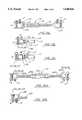
- FIG. 1is a posterior view of a spinal column with a certain embodiment of the present invention surgically installed thereon
- FIG. 2is a left side view of the left most portion of the embodiment of the present invention shown in FIG. 1;
- FIG. 3is a right side view of the right most portion of the embodiment of the present invention shown in FIG. 1;
- FIG. 4is a perspective view of a certain embodiment of the right-hand double barrel laminar hook
- FIG. 4ais a bottom view of the right-hand double barrel laminar hook shown in FIG. 4;
- FIG. 5is a perspective view of a certain embodiment of the left-hand double barrel laminar hook
- FIG. 6is a bottom view of a certain embodiment of the left-hand double barrel laminar hook configured to accommodate quadrilateral shaped rods;
- FIG. 7aillustrates a front view of a certain embodiment of the single barrel laminar hook
- FIG. 7billustrates a side view of a certain embodiment of the single barrel laminar hook
- FIG. 7cillustrates a bottom view of a certain embodiment of the single barrel laminar hook
- FIG. 8ais an exploded view of a certain embodiment of the pedicular bolt clamp and a corresponding pedicular bolt;
- FIG. 8bis an exploded view of a certain embodiment of the slotted pedicular bolt clamp and a corresponding pedicular bolt;
- FIG. 8cis a side view of a certain embodiment of the pedicular bolt clamp
- FIG. 8dis a side view of a certain embodiment of the pedicular bolt clamp configured to accommodate a quadrilateral shaped rod;
- FIG. 9is an exploded view of a cylindrical rod assembly which shows a female rod and two possible embodiments of interchangeable male cylindrical rod components
- FIG. 10is an exploded view of a quadrilateral rod assembly which shows a female rod and two possible embodiments of interchangeable male quadrilateral rod components;
- FIG. 11aillustrates a certain embodiment of an adjustable cross bar assembly
- FIG. 11bshows a detail of one end of the adjustable cross bar assembly shown in FIG. 11a;
- FIG. 11cshows a detail of one end of a certain embodiment of an adjustable cross bar assembly which is configured to accommodate a quadrilateral shaped rod;
- FIG. 12ashows a certain embodiment of a turnbuckle cross bar assembly
- FIG. 12bshows a detail of one end of the turnbuckle cross bar assembly shown in FIG. 12a.
- FIG. 1a spinal fixation system is illustrated showing one of many different potential arrangements of the individual components which are a part of this novel spinal fixation system.
- the arrangementillustrates one possible combined use of the right-hand double barrel laminar hook 40a, 40b (FIGS. 4, 4a), the single barrel laminar hook 70a, 70b (FIGS. 7a, 7b, 7c), the pedicular bolt clamp assembly 80 (FIGS. 8a, 8c, 8d), the cylindrical rod assembly 90 (FIG. 9) and the adjustable cross bar assembly 110 (FIGS. 11a, 11b, 11c).
- the double barrel laminar hook 40(FIGS. 4, 4a) is identical to the double barrel laminar hook 40a, 40b shown installed in FIGS. 1, 2 and 3.
- the single barrel laminar hook 70(FIGS. 7a, 7b, 7c) is identical to the single barrel laminar hook 70a, 70b shown installed in FIGS. 1, 2 and 3.
- FIG. 2illustrates a side view of the spine shown posteriorly in FIG. 1 and also shows the construct installed on the left most side of the spine.
- a single barrel laminar hook 70b(FIGS. 7a, 7b, 7c) is shown surgically connected to the inferior border of the lamina of the L1 vertebra.
- a right-hand double barrel laminar hook 40a(FIG. 4) is shown surgically connected to the superior border of the T11 lamina.
- a cylindrical rod 92b(FIG.
- FIG. 9is shown connected to the single barrel laminar hook 70b at one end and the right-hand double barrel laminar hook 40a (FIG. 4) at the other end.
- the combined assembly of the installed single barrel laminar hook 70b and the right-hand double barrel laminar hook 40a interconnected with the cylindrical rod member 92bcreates a clawing action across the L1 and the T11 vertebra.
- One end of the cylindrical rod member 92bis secured within the bore of the single barrel laminar hook 70b with a set screw 12; while the other end of the cylindrical rod member 92b is secured within the bore of the right-hand double barrel laminar hook 40a with set screw 12a (See FIGS. 4a, 7b).
- a single barrel laminar hook 70a(FIGS. 7a,7b,7c) is shown surgically attached to the inferior border of the lamina of the T4 vertebra.
- the offset cylindrical male rod member 94awhich is one component of the overall cylindrical rod assembly 90 (FIG. 9), is attached to the single barrel laminar hook 70a.
- the offset cylindrical male rod member 94ais inserted into the cylindrical rod coupler 96a (FIG. 9) and secured therein with at least one (1) rod coupler set screw 16.
- the cylindrical rod coupleris integral to the straight cylindrical female rod member 98a (FIG. 9) which is secured within the slot of the right-hand double barrel laminar hook 40a (FIG. 4).
- a right-hand double barrel laminar hook 40b(FIG. 4) is shown surgically connected to the inferior border of the lamina of the L1 vertebra.
- a single barrel laminar hook 70c(FIGS. 7a, 7b, 7c) is shown surgically connected to the superior border of the lamina of the T11 vertebra.
- the cylindrical rod member 92c(FIG. 9) is interconnected between the single barrel laminar hook 70c and the right-hand double barrel laminar hook 40b.
- One end of the cylindrical rod member 92cis secured within the bore of the single barrel laminar hook 70c with a set screw 12; while the other end of the cylindrical rod member 92c is secured within the bore of the right-hand double barrel laminar hook 40b (FIG. 4) with set screw 12a.
- a pedicular bolt clamp 80(FIG. 8a) is shown installed on the pedicle of the T5 vertebra
- the pedicular bolt clamp 80attaches to a previously installed pedicular bolt.
- the slotted pedicular bolt clamp 85(FIG. 8b) may also be used in combination with a pedicular bolt and the present invention.
- a detailed explanation of the operation of the pedicular bolt clamp and the slotted pedicular bolt clampis included in the pedicular bolt clamp section below.
- the pedicular bolt clamp 80is interconnected to the lower right-hand double barrel laminar hook 40b with a cylindrical rod construct 90b (FIG. 9).
- the cylindrical rod assembly 90bincludes an offset cylindrical male rod member 94b which is connected to a straight cylindrical female rod member 98d with a cylindrical rod coupler 96b.
- the offset cylindrical male rod member 96bis inserted into the cylindrical rod coupler 96 and securely attached with at least one (1) set screw 16.
- the cylindrical rod assembly 90bis inserted into the slot in the right-hand double barrel laminar hook 40b and the slot 810 in the slotted clamp of the pedicular bolt clamp (see FIG. 8a).
- the slot 810is wider than the diameter of the rod members, it is relatively easy to position the rod member within the slot. Precise alignment is generally not necessary. This can reduce the amount of time required for the surgical installation.
- FIGS. 1,2 and 3An adjustable cross bar assembly 110, (FIG. 11a, 11b, 11c) embodiment of the present invention is illustrated in FIGS. 1,2 and 3 on the upper portion of the construct.
- a turnbuckle crossbar assemblyis shown on the lower portion of the construct.
- the adjustable cross bar assembly 110ais connected between the individual spinal fixation constructs to provide structural support and rigidity between the constructs.
- the rotating C-shaped end member 112a of the adjustable cross bar assembly 110ais positioned around the offset cylindrical male rod member 94a and secured to the rod member 94a with set screw 12 (see FIG. 11).
- Set screw 14secures the rod member 94a within the interior of the C-shaped end member 112b.
- the stationary C-shaped end member 112b of the adjustable cross bar assembly 110ais positioned around the offset cylindrical male rod member 94b and secured to the offset cylindrical male rod member 94b with set screw 12.
- Set screw 14secures the cylindrical male rod member 94b within the interior of the C-shaped end member 112b.
- turnbuckle cross bar assembly 120(FIG. 12a, 12b) is connected between the straight cylindrical male rod member 98a and the straight cylindrical male rod member 98d.
- the turnbuckle cross bar assembly 120may also be used to selectively adjust and secure the spinal fixation constructs shown in FIGS. 1,2 and 3.
- the quadrilateral assembly 100(FIG. 10) may be used instead of the cylindrical rod assembly 90 (FIG. 9).
- the quadrilateral rodsprovide torsional stability and help to prevent undesireable rotation and micromotion of the spinal fixation system.
- Table 1lists a summary of parts, including the corresponding description and figure numbers.
- the right-hand double barrel laminar hook 40includes a laminar hook 42, a body 45, an upper leg member 43, a lower leg member 44, short set screws 12a, 12b and a long set screw 14.
- the laminar hook 42is attached to the face 43 of the body 45.
- the laminar hook 42is arcuate in shape and may be formed with a relatively small or a relatively large radius of curvature. In this way, the overall profile of the hook body 17 or 25 can be kept to a minimum.
- the radius of curvaturecan be relatively small but when the hook is used on the thoracic or lumbar portions of the spine, a relatively large radius of curvature may be desired.
- a variety of different hookscan be made available to be used with the present invention, including, but not limited to hooks that can be used for laminar attachments and hooks that can be used for pedicular attachments.
- the body 45includes a bore 48 that is adapted to receive a cylindrical connecting rod 92, 94, 98 (FIG. 9) therethrough.
- the bore 48may also be oval in shape to provide the double barrel laminar hook with additional range of movement relative to the cylindrical member during installation.
- FIG. 4aa bottom view of the right-hand double barrel laminar hook 40 is shown.
- Two short set screws 12a and 12bare threaded into the side of body 45 wherein the short set screws 12a and 12b engage and secure the side of the cylindrical rods 92, 94, 98 (FIG. 9).
- the bodyincludes a slot 46 on one end which allows the relatively easy insertion of a cylindrical rod 92, 94, 98 (FIG. 9) therein.
- the cylindrical rod 92, 94, 98 (FIG. 9)is securely positioned in the base of the slot 46 by rotating the long set screw 14 until it resistively engages against the inside of the opposite fork wall.
- the left-hand double barrel laminar hook 50 embodiment of the present inventionis illustrated.
- the left-hand double barrel laminar hook 50is essentially identical to the right-hand double barrel laminar hook 40.
- the left-hand orientation of the left-hand double barrel laminar hookallows the surgeon to position the slot 46, away from the spinal axis during the surgical installation.
- the bore 66is quadrilateral in cross section to accommodate any of the quadrilateral rods 102, 104, 108 (FIG. 10).
- the square bore 66may be larger in the clamping width than the width of the quadrilateral rod to be used thereby allowing a greater range of motion of the quadrilateral double barrel laminar hook 60 relative to the quadrilateral rod during the surgical installation.
- cylindrical rods 92, 94, 98(FIG. 9) may also be installed in the bore 66.
- the square slot 64is adapted to receive a quadrilateral rod member 102, 104, 108 (FIG. 10) therein.
- the quadrilateral right-hand double barrel laminar hook 60includes long set screw 14 that is rotated clockwise until it resistively engages against the inside of the opposite fork wall.
- the quadrilateral rod member 102, 104, 108(FIG. 10) is still free to move within slot 64 relative to the body 62.
- the quadrilateral rod member 102, 104, 108(FIG.
- the unitary laminar hook clamp 70includes a body 72 and a laminar hook 42.
- the body 72is substantially cylindrical and includes a bore 73 therethrough to receive one of the cylindrical rods 92, 94, 98 (FIG. 9).
- Bore 73may also be oval in cross section to provide a greater range of motion of the unitary laminar hook clamp 70 relative to the rod 92, 94, 98 during the surgical installation.
- Short set screw 12is threaded into the corresponding threaded hole 74 to engage and firmly secure the outer surface of cylindrical rod 92, 94 or 98.
- the bore 73 of the unitary laminar hookmay also be quadrilateral in shape to correspond to quadrilateral rods 102, 104 or 108 (FIG. 10).
- FIG. 8aan exploded view of the pedicular bolt clamp 80 embodiment of the present invention is illustrated.
- the pedicular bolt clampincludes a body 826, a C-shaped clamp 806, a nut 802, a short set screw 12 and a long set screw 14. Also illustrated in FIG. 8a is a pedicular bolt 88.
- a pedicular boltis shown in U.S. Pat. No. 5,242,443, which is incorporated herein by reference.
- the body 826includes an inner bore 820 and an outer bore 822.
- the inner boreis sufficiently large in diameter to allow the threaded end 828 of the pedicular bolt 88 to extend therethrough.
- the diameter of the middle portion 830 of the pedicular bolt 88is larger than the diameter of the inner bore 820 thereby causing the upper ledge 832 to engage the inner surface between the inner bore 820 and the outer bore 822 of the body 826.
- the C-shaped clamp 806includes a bore 804 through which the threaded end 828 of the pedicular bolt 88 extends.
- the C-shaped clampalso includes interdigitating grooves 808 on the inner surface thereof.
- the flat region 816 of the body 826also includes corresponding interdigitating grooves 818.
- the interdigitating grooves 808 on the C-shaped clampare designed to engage the interdigitating grooves 818 of the flat region 816. Furthermore, when the C-shaped clamp 806 is positioned on the top of the flat region 816 of the body 826, the threaded end 828 of the pedicular bolt 88 will extend through the bore 804. The nut 802 is then threaded onto the threaded end 828 of the pedicular bolt 88. Once the body 826 has been oriented to the desired position, the nut 802 is tightened to secure the body 826 to the pedicular bolt.
- the C-shaped clampprovides a superior compressive bearing surface between the nut 802 and the flat region 816 of the body 826.
- FIG. 8ba certain slotted pedicular bolt clamp 85 embodiment of the present invention is illustrated.
- the slotted pedicular bolt clamp 85is similar in configuration to the pedicular bolt clamp 80.
- a slotted opening 854having an inner slot 850 and an outer slot 852 is also provided.
- the inner slot 850is sufficiently wide to allow the threaded end 828 of the pedicular bolt 88 to extend therethrough.
- the diameter of the middle portion 830 of the pedicular bolt 88is larger than the diameter of the inner slot 850 thereby causing the upper ledge 832 to engage the inner surface between the inner slot 850 and the outer slot 852 of the body 826.
- the slotted opening 854allows the slotted bolt clamp 85 to be adjusted by positioning the slotted opening 854 at the desired position relative to the pedicular bolt 88.
- the C-shaped clamp 806, which is described above,is placed on top of the flat region 816 of the body 826.
- the interdigitating grooves 808 on the C-shaped clampengage the corresponding interdigitating grooves on the flat region 816 of the body 826.
- the threaded end 828extends through the slot opening 854 and through the bore 804.
- the nut 802is threaded onto the threaded end 828 to secure the pedicular bolt body 826 to the pedicular bolt 88.
- FIG. 8ca side view of the pedicular bolt clamp 80 embodiment of the present invention is illustrated.
- FIG. 8cillustrates the slot 810 designed to be used with cylindrical rod members (90, 92, 94).
- FIG. 8da side view of the pedicular bolt clamp 80 is illustrated having a slot 812 designed to be used with quadrilateral rod members (100, 102, 104).
- the slot configurations shown in FIGS. 8c and 8dmay, of course, also be used with the slotted pedicular bolt clamp 85.
- the cylindrical rod assembly 90includes a straight cylindrical female rod member 98, a cylindrical rod coupler 96, a straight cylindrical male rod member 92, an offset cylindrical male rod member 94 and a rod coupler set screw 16.
- the cylindrical connecting rods 92, 94, 98are typically five or seven millimeters in diameter.
- the rod coupler 96is welded or otherwise coupled to the stationary straight rod member 98. Either the straight cylindrical male rod member 92 or the offset cylindrical male rod member 94 may be inserted into the rod coupler bore 97. Once inserted, the removable cylindrical rod member 92, 94 may be securely attached within the rod coupler by tightening the rod coupler set screw 16 against the outer surface of the cylindrical male rod member 92, 94. It is understood that the lengths of the cylindrical rod members 92, 94 and 98 may be provided in varying lengths to suit the particular surgical requirement. The rod members may also be cut to the appropriate length during the surgical installation procedure.
- quadrilateral rod assembly 100is illustrated.
- the quadrilateral rod assembly 100is substantially identical to the cylindrical rod assembly 90 which was previously described in detail.
- the essential difference between quadrilateral rod assembly 100 and the cylindrical rod assembly 90is the shape of the rod members and rod coupler members. It may be desirable to use quadrilateral members because of the superior torsional characteristics which the quadrilateral members provide.
- FIG. 11aan adjustable cross bar assembly 110 embodiment of the present invention is illustrated.
- the adjustable cross bar assembly 110includes a rotating C-shaped end member 112a, a swivel connector 114, an oval head member 119a, a socket member 115, a threaded pin member 118, a stationary C-shaped end member 112b, a short set screw 12 and a long set screw 14.
- the swivel connector 114is attached to the closed end of the socket member 115 and extends through the base of the rotating C-shaped end member 112a.
- An oval head member 119ais attached to the end of the swivel connector thereby securing the rotating C-shaped end member 112a to the socket member 115.
- the socket member 115may have a knurled outer surface or other engagement surface such as a hexagonal surface for engagement by a wrench.
- the threaded pin member 118engages corresponding threads in the threaded bore of the socket member 115.
- the stationary C-shaped end member 112bis integral to one end of the threaded pin 118. Both of the C-shaped end members 112a, 112b have a short set screw 12 and a long set screw 14 threaded into one side thereof. Each of the short set screws 12 on the rotating C-shape end member 112a and on the stationary C-shaped end member 112b are used to engage the outside surface of a cylindrical rod member 92, 94, 98 (FIG. 9) or a quadrilateral rod member 102, 104, 108 (FIG. 10).
- Each of the long set screws 14 on the rotating C-shape end members 112a and on the stationary C-shaped end member 112bare used to secure cylindrical rod member 92, 94, 98 or a quadrilateral rod member 102, 104, 108 within the interior of the respective C-shaped end member 112a, 112b.
- FIG. 11ban alternative end member embodiment of the present invention is shown.
- the C-shaped end member 112cincludes a countersunk bore 113 in which the head member 119b is positioned.
- the threaded swivel pin 111may have a countersunk hex head to engage for tightening.
- the threaded swivel pin 111is threaded into the corresponding bore 117.
- a slight gapis created between the head 119b of the threaded swivel pin 111 and the countersunk bore 113.
- a washer 116provides a bearing surface between the end of the C-shaped end member 112c and the socket member 115.
- FIG. 11ca C-shaped end member 112d embodiment of the present invention is shown.
- the C-shaped end member 112dis substantially identical to the C-shaped end member 112c shown in FIG. 11b. However, the C-shaped end member has orthogonal inner surfaces and 112d is thereby adapted to receive one of the quadrilateral rod members 102, 104 or 108.
- the quadrilateral rod member 102, 104 or 108may be secured within the C-shaped end member 112d by tightening the short set screw 12.
- the quadrilateral rod member 102, 104 or 108may be further secured by tightening the long set screw 14 until it contacts the inner wall of the opposite leg member as illustrated in FIG. 11c.
- FIG. 12aa turnbuckle cross bar assembly 120 embodiment of the present invention is shown.
- the turnbuckle cross bar assembly 120includes two (2) C-shaped end members 122a, 122b, two (2) threaded pin members 124a, 124b, a turnbuckle nut 126, a short set screw 12 (one on each end) and a long set screw (one on each end).
- the C-shaped end member 122ais adapted to receive a cylindrical rod member 92, 94, 98.
- Both of the C-shaped end members 122a, 122bhave a short set screw 12 and a long set screw 14 threaded into one side thereof.
- Each of the short set screws 12 on the rotating C-shape end members 122a, 122bare used to engage the outside surface of a cylindrical rod member 92, 94, 98 (FIG. 9).
- Each of the long set screws 14 on the rotating C-shape end members 122a, 122bare used to secure cylindrical rod member 92, 94, 98 within the interior of the respective C-shaped end member 122a, 122b.
- the C-shaped end member 122ais integral to the threaded pin 124a.
- the threaded pin 124ais threaded into one end of the turnbuckle nut 126.
- Threaded pin 124bis integral to the C-shaped end member 122b.
- the threaded pin 124bis threaded into the opposite end of the turnbuckle nut 126.
- Threaded pin 124a and threaded pin 124bhave alternate thread directions wherein one of the threaded pins 124a, 124b has a right hand thread, and the other of the threaded pins 124a, 124b has a left hand thread.
- the corresponding turnbuckle nut 126has right hand threads on one end and left hand threads on the other end.
- FIG. 12ban alternative embodiment of a quadrilateral end member 128 is shown.
- the quadrilateral end member 128is configured with an orthogonal internal pocket wherein the quadrilateral end member 129 can be attached to one of the quadrilateral rod members 102, 104, 108.
- the quadrilateral rod member 102, 104, 108is secured within the pocket of the quadrilateral end member by tightening the short set screw 12.
- the quadrilateral rod member 102, 104, 108is further restrained within the internal pocket by fully tightening the long set screw 14 until the long set screw 14 resistively engages the inside wall of the opposite leg of the quadrilateral end member 129.
- FIGS. 1, 2 and 3wherein the double barrel spinal fixation system is illustrated which allows the surgeon to construct a rigid, laminal claw that is independent of the rod system.
- the surgeonfollows conventional surgical procedures to expose the effected portion of the spine.
- the following method descriptionis one possible variation illustrated in FIGS. 1, 2 and 3. It should be understood that the surgeon is free to assemble the spinal construct with individual components described variously herein and assemble the construct in the most desired manner.
- a single laminar hook 70(FIG. 7) is typically surgically attached to the lamina of the selected vertebra.
- a straight cylindrical male rod member 92 or offset cylindrical male rod member 94may be loosely inserted into the bore 73 (FIG. 7) of the single laminar hook.
- a right hand or left hand double barrel laminar hook 40, 50(FIGS. 4, 5) is then surgically attached to the lamina of the selected vertebra.
- a right-hand double barrel laminar hook 40ais shown in FIGS. 1 and 2 surgically connected to the lamina of the superior border of the T11 lamina.
- the cylindrical rod member 92may be inserted into the bore 48a, 48b of the double barrel laminar hook 40a, 40b either after the double barrel laminar hook has been connected to the desired lamina or prior to the surgical installation.
- the short set screw 12 on the single barrel laminar hook 70 and the short set screw 12a on the double barrel laminar hookmay be tightened to secure the cylindrical rod member to the laminar hooks and to prevent any micromotion across the lamina.
- the compressire clawing actionmay be across single lamina or across multiple lamina.
- the surgeoncan then proceed with the installation of an additional single barrel laminar hook 70 (FIGS. 7a, 7b, 7c) or a pedicular bolt clamp assembly 80 (FIGS. 8a, 8b, 8c).
- an additional single barrel laminar hook 70 or pedicular bolt assembly 80the surgeon can proceed with the reduction and fixation of the spine by connecting a rod assembly 90 (FIG. 9) between the single barrel laminar hook 70 or the pedicular bolt clamp assembly 80 and the double barrel laminar clamp 40, 50.
- a single barrel laminar hook 70ais shown surgically attached to the inferior border of the proximal lamina of the T4 vertebra on the left most concave side of the spine.
- the cylindrical rod assembly 90ainterconnects the single barrel laminar hook 70a and the right-hand double barrel laminar hook 40a.
- the offset cylindrical male rod member 94ais inserted into the bore 73 of the single barrel laminar hook 70a (FIGS. 7a, 7b, 7c) and secured by tightening the short set screw 12.
- the straight cylindrical female rod member 98ais inserted into the slot 46a of the right-hand double barrel laminar hook 40a (FIG. 4).
- the short set screw 12bmay then be tightened to secure the straight cylindrical female rod member 98a within the slot 46a.
- the long set screw 14may then be fully tightened to engage the inside of the opposite inside wall to confine the straight cylindrical female rod member within the slot 46a.
- the long set screw 14may be tightened first, securing the rod member within the slot 46a, and subsequently the short set screw 12 may be tightened to secure the rod member to the double barrel clamp.
- the cylindrical rod assembly 90ais comprised of several individual components which may be installed as an assembly or may be installed one piece at a time. This flexible design can save the surgeon time by permitting him or her to complete the connection between the laminar clamps or between a laminar clamp and a pedicular bolt in two stages.
- a pedicular bolt clamp 80is shown surgically installed on the pedicle of the T5 vertebra on the right most convex side of the spine.
- the pedicular bolt clamp 80is installed by first placing the body 826 onto the previously installed pedicular bolt (FIG. 8a, 8b).
- the threaded end 828 of the pedicular bolt 88extends through the inner bore 820 whereby the C-shaped clamp 806 may be placed over the body 826.
- the threaded end 828then extends through the bore 804 of the C-shaped clamp 806.
- the interdigitating grooves 808 on the inside surface of the C-shaped clamp 806engage the interdigitating grooves 818 on the outside of the pedicular bolt clamp 80.
- the body 826may be rotated about the pedicular bolt 88 until the desired orientation is achieved.
- the nut 802may be attached prior to, or after, the desired orientation is achieved. Once the body 826 is in the desired position, the nut 802 may be tightened with an appropriate wrench.
- a slotted pedicular bolt clamp 85may be installed on an existing pedicular bolt.
- the installation of the slotted pedicular bolt clamp 85is similar to the installation of the pedicular bolt clamp 80.
- the slotted pedicular bolt clamp 85allows the surgeon to variably position the body 826 relative to the spinal axis.
- the body 826 of the slotted pedicular bolt clamp 85is placed onto the previously installed pedicular bolt 88, wherein the threaded end 828 of the pedicular bolt 88 extends through the slot opening 854.
- the position of the body 826is then adjusted relative to the spinal axis by positioning threaded end 828 in the desired position within the slotted opening 850.
- the slotted opening 854allows the body 826 to be rotated and adjusted laterally relative to the pedicular bolt 88 and the spinal axis.
- the C-shaped clampis placed over the threaded end 828 of the pedicular bolt 88 and the nut 802 is threaded onto the threaded end 828 and tightened to the desired torsion.
- the interdigitating grooves 808 on the inside of the C-shaped clampengage the interdigitating grooves 818 on the outside of the body 826 to provide a secure assembly.
- the clawing construct and the pedicular bolt clamp 80are interconnected with the cylindrical rod assembly 90b (FIG. 9).
- the offset cylindrical male rod member 94bis inserted into the slot 810 of the pedicular bolt clamp 80 and secured to the pedicular bolt clamp 80 by tightening the short set screw 12 (FIG. 8a).
- the long set screw 14is tightened to further secure the rod member within the slot 810.
- the long set screwmay be tightened first, securing the rod within the slot, and subsequently the short set screw may be tightened.
- the straight cylindrical female rod member 98dis inserted into the slot 46a of the right-hand double barrel laminar hook 40b.
- the rod memberis secured within the slot by tightening the short set screw 12 first, and then tightening the long set screw 14.
- the long set screw 14may be tightened first and then the short set screw may be tightened, depending upon the surgeon's preference.
- An adjustable cross bar memberis typically installed by the surgeon after the spinal fixation assemblies have been installed.
- Two (2) adjustable cross bar member embodiments of the present inventionare shown in FIGS. 1, 2 and 3.
- the adjustable cross bar assembly 110is shown on the upper, thoracic region of the spine.
- the turnbuckle cross bar assembly 120is shown on the lower thoracic region of the spine.
- Either of the cross bar assemblies 110 or 120may be attached to the rod system at the end of the operative procedure without the need to place the appropriate parts for construction of the cross bar on the rod before the laminar hooks or pedicular clamps are installed. If the adjustable cross bar assembly 110 is being used, the C-shaped end members 112a and 112b are positioned around the longitudinal or quadrilateral rods which are being used in the spinal fixation system. Subsequently, the long set screws 14 are tightened to secure the C-shaped end members onto the corresponding rod members.
- the socket memberis adjusted with a corresponding nut or pliers to achieve the desired degree of separation or tension between the longitudinal rod constructs positioned on each side of the spine.
- the adjustable cross bar assembly 110is properly adjusted, the short set screws are tightened against the longitudinal cylindrical or quadrilateral members.
- the overall structureprevents micromotion between the vertebra, and between the individual components of the assembly.
- the overall structurealso helps to provide torsional stability.
- the socket member 115may also be secured to the threaded pin member with a cotter pin or other restraining device.
- the turnbuckle cross bar assembly 120is installed in essentially the same manner as the adjustable cross bar assembly 110. However, the turnbuckle cross bar assembly 120 is adjusted between the cylindrical or quadrilateral longitudinal members by rotating the turnbuckle nut clockwise or counterclockwise until the desired separation and tension between the longitudinal members is achieved.
- the nut 126may also be secured to one or both of the threaded pin members 124a, 124b with a cotter pin, or other restraining device.
Landscapes
- Health & Medical Sciences (AREA)
- Orthopedic Medicine & Surgery (AREA)
- Life Sciences & Earth Sciences (AREA)
- Neurology (AREA)
- Surgery (AREA)
- Heart & Thoracic Surgery (AREA)
- Engineering & Computer Science (AREA)
- Biomedical Technology (AREA)
- Nuclear Medicine, Radiotherapy & Molecular Imaging (AREA)
- Medical Informatics (AREA)
- Molecular Biology (AREA)
- Animal Behavior & Ethology (AREA)
- General Health & Medical Sciences (AREA)
- Public Health (AREA)
- Veterinary Medicine (AREA)
- Surgical Instruments (AREA)
Abstract
Description
The present invention relates to the field of spinal correction devices. More specifically, the present invention is directed to a double barrel spinal fixation system and method that allow an operating surgeon to construct a rigid laminal claw across one or more vertebrae and provide subsequent independent reduction and fixation of a spinal deformity.
The use of spinal fixation systems is known. Such systems are used to correct spinal deformities such as: kyphosis, lordosis, hemivertebra, spondylolisthesis, scoliosis and others. Kyphosis is a sharp, angular rearward curvature. Lordosis is a forward accentuation of the cervical or lumbar regions beyond physiological levels. Hemivertebra is a developmental error in the spine caused by lack of formation of a vertebral body growth center which results in the production of wedge-shaped vertebrae or one-half of a vertebra. Spondylolisthesis is a spinal deformity in which a vertebral body with the vertebral column above it subluxes or glides forward on the vertebral body below. Scoliosis is characterized by a lateral curvature of a segment of the spine from the normally straight midline position. Other causes of spinal deformities include, but are not limited to, fractured vertrebral bodies or dislocated spinal segments. Spinal fixation systems are also used to correct spinal instability. Primary instability may be acute, for example, as caused by trauma; or may be chronic, for example, as caused by degeneration or by a tumor. Secondary instability may be caused by resection, for example, by a facetectomy. Secondary instability may also be caused by overload, for example, by a misalignment or from stress concentrations.
Many existing spinal fixation systems include rod and hook components used for reduction and fixation of the spinal column. However, the existing systems require the assembly of many different intricate components that ultimately cause the surgical procedure to be complicated and unnecessarily delayed.
For example, U.S. Pat. No. 5,102,412 to Rogozinski shows a spinal rod system and method for instrumenting the spine in the treatment of spinal abnormalities. The system comprises many intricate parts. Such parts include U-shaped screw couplers for use with pedicular screws. The screw couplers are assembled with cross bars and set screws. The laminar clawing configuration requires the additional assembly of a hook bar and a set screw. Another example of spinal instrumentation is known as the Multiple Axial Stabilization System (MASS). This system uses open hooks and cable hooks. Clawing of lamina is accomplished by interconnecting either cable hooks with open hooks, or by interconnecting a pair of cable hooks. A longitudinal rod can subsequently be inserted into the groove in the open slot outside of the open hook. Provided absolute alignment with the groove is established, a sleeve can be positioned outside the rod and integral with the open hook to secure the hook to the rod. It has been found in practice that it is often cumbersome to align the rod with the groove in the clamp. The improper alignment between the rod and the groove can cause the insertion of the sleeve into the hook to be difficult. In addition, the cabling system is not sufficiently rigid to provide rotational stability.
The Isola spinal implant system is a further example of spinal instrumentation and is described in Spinal Instrumentation, pp. 324-351 (1992). The Isola system uses anchor components consisting of screws, posts, hooks and wires. Closed body and open body hooks are used. The anchors, and in particular, the hooks, are used to interconnect longitudinal rods to achieve the desired correction of spinal deformity about the sagittal plane. The hooks are placed in operative association with selected lamina while simultaneously interconnecting the longitudinal rod members.
Similarly, the Correl-Dubousset Instrumentation includes closed and open hook bodies. The hooks are used as anchor points to interconnect a flexible rod. A closed body hook and an open body hook may be used to span one or more lamina but such an installation is still integral to the total longitudinal rod component and does not allow an independent clawing of the selected lamina.
It is desirable to have a device that will allow an operating surgeon to construct a rigid laminal clamp that is independent of the rod system. The device should allow the surgeon to be able to concentrate upon the task of clawing one or multiple lamina without having to simultaneously coordinate the installation of the rod system. The device should also be easy to assemble and should provide torsional stability to correct rotational deformity of the spine. The device should be adaptable for use with pedicular bolts and with laminar hooks. The device should also be easy to install by allowing the surgeon to readily insert the longitudinal rod into the slot of the clamp and thereafter to secure the longitudinal rod when it is in the correct position.
The present invention provides a new and improved system and method for constructing a rigid laminal claw that is independent of the rod system. The clawing action may include a single lamina process or may include several lamina segments. When the clawing action is completed, the operating surgeon can proceed with the installation of secondary rods to effect the desired reduction and fixation of the spinal deformity.
In certain embodiments, the present invention is directed to a method of constructing a rigid laminal claw system which is independent of the spinal rod system and comprises the steps of: (a) surgically exposing the spine posteriorly, (b) clawing single or multiple lamina by interconnecting at least two clawing apparatus, (c) reducing and fixating the deformity of the spine by interconnecting the at least two clawing apparatus.
The present invention is readily adaptable to be used with both laminar claw engagements and to pedicular attachments with pedicular screws. The device is modular in configuration which allows the operating surgeon flexibility during the surgical installation procedure. The appropriate modular component of the invention can be implemented as needed at the appropriate time during the installation.
In another certain embodiment of the present invention a surgically implantable spinal fixation system is shown which comprises a body member having two parallel faces and an orifice therethrough which is adapted to receive a longitudinal rod member. The rod member is typically circular or quadrilateral in cross section. During the surgical installation the orifice is positioned generally along the spinal axis. The body member also has a slot that is positioned along at least one end along the spinal axis whereby a second rod member can easily be inserted into the slot from one end of the body. A laminar hook member is attached to the outer surface of one leg member. One leg member includes a threaded hole adapted to receive a threaded set screw. The set screw extends through the leg member and engages the outer surface of the rod member. The leg member also includes a second threaded hole adapted to receive a second set screw. The second set screw extends through the first leg member and engages the outer surface of the second rod member. The first leg member also includes a threaded hole adapted to receive a third set screw whereby the third threaded member extends through the first leg member and extends along at least one side of the second rod member.
The engagement between the rod members and the set screw members provides a secure and stable overall interface between the clamping members and the rod system. The secure overall interface provides desired torsional strength to the resulting spinal fixation assembly.
In addition, this invention provides the operating surgeon with the advantage of being able to successfully seat the rod member securely into the clamp slot with relative ease. The slots provided on the present inventive clamp members typically are wider across than the cross section of the rod to be inserted therein. It becomes a relatively simple matter for the surgeon to align the rod within the slot in which the appropriate set screw can be rotated into position to secure the rod within the rod slot. After the rod has been secured within the slot, the appropriate set screw can be rotated into position to bear against the side of the rod member.
An additional advantage of the present invention is that the modular components which comprise the system are relatively few. As a result, the system is less complicated, requiring a smaller inventory of parts to create a fully functional spinal fixation system.
Another advantage of the present invention is that the slotted pedicular bolt clamp allows the surgeon to position the pedicular bolt clamp to the pedicular bolt in a wide range of different positions. The slotted pedicular bolt clamp may be rotated and repositioned laterally relative to the spinal axis to provide the optimum alignment of the clamp slot to the longitudinal rod member.
Yet further, because the installation of the present invention is simplified for the surgeon, the total time required for surgical installation is reduced. In practice, a patient may indeed experience stress because of prolonged exposure to invasive surgery. The reduction in the time required for surgery provided by the present invention benefits the patient by reducing the patient's exposure to the corresponding amount of time and surgical related stress.
The foregoing and other features of the invention will become more apparent upon a consideration of the following description taken with the accompanying drawings, wherein:
FIG. 1 is a posterior view of a spinal column with a certain embodiment of the present invention surgically installed thereon
FIG. 2 is a left side view of the left most portion of the embodiment of the present invention shown in FIG. 1;
FIG. 3 is a right side view of the right most portion of the embodiment of the present invention shown in FIG. 1;
FIG. 4 is a perspective view of a certain embodiment of the right-hand double barrel laminar hook;
FIG. 4a is a bottom view of the right-hand double barrel laminar hook shown in FIG. 4;
FIG. 5 is a perspective view of a certain embodiment of the left-hand double barrel laminar hook;
FIG. 6 is a bottom view of a certain embodiment of the left-hand double barrel laminar hook configured to accommodate quadrilateral shaped rods;
FIG. 7a illustrates a front view of a certain embodiment of the single barrel laminar hook;
FIG. 7b illustrates a side view of a certain embodiment of the single barrel laminar hook;
FIG. 7c illustrates a bottom view of a certain embodiment of the single barrel laminar hook;
FIG. 8a is an exploded view of a certain embodiment of the pedicular bolt clamp and a corresponding pedicular bolt;
FIG. 8b is an exploded view of a certain embodiment of the slotted pedicular bolt clamp and a corresponding pedicular bolt;
FIG. 8c is a side view of a certain embodiment of the pedicular bolt clamp;
FIG. 8d is a side view of a certain embodiment of the pedicular bolt clamp configured to accommodate a quadrilateral shaped rod;
FIG. 9 is an exploded view of a cylindrical rod assembly which shows a female rod and two possible embodiments of interchangeable male cylindrical rod components;
FIG. 10 is an exploded view of a quadrilateral rod assembly which shows a female rod and two possible embodiments of interchangeable male quadrilateral rod components;
FIG. 11a illustrates a certain embodiment of an adjustable cross bar assembly;
FIG. 11b shows a detail of one end of the adjustable cross bar assembly shown in FIG. 11a;
FIG. 11c shows a detail of one end of a certain embodiment of an adjustable cross bar assembly which is configured to accommodate a quadrilateral shaped rod;
FIG. 12a shows a certain embodiment of a turnbuckle cross bar assembly;
FIG. 12b shows a detail of one end of the turnbuckle cross bar assembly shown in FIG. 12a.
In FIG. 1, a spinal fixation system is illustrated showing one of many different potential arrangements of the individual components which are a part of this novel spinal fixation system. The arrangement illustrates one possible combined use of the right-hand double barrellaminar hook 40a, 40b (FIGS. 4, 4a), the single barrellaminar hook laminar hook 40a, 40b shown installed in FIGS. 1, 2 and 3. Similarly, the single barrel laminar hook 70 (FIGS. 7a, 7b, 7c) is identical to the single barrellaminar hook
Refer now to FIG. 1, a posterior view of a portion of the lumbar and the thoracic spine are illustrated. FIG. 2 illustrates a side view of the spine shown posteriorly in FIG. 1 and also shows the construct installed on the left most side of the spine. On the left most, distal side of the spinal axis, a single barrellaminar hook 70b (FIGS. 7a, 7b, 7c) is shown surgically connected to the inferior border of the lamina of the L1 vertebra. A right-hand double barrellaminar hook 40a (FIG. 4) is shown surgically connected to the superior border of the T11 lamina. A cylindrical rod 92b (FIG. 9) is shown connected to the single barrellaminar hook 70b at one end and the right-hand double barrellaminar hook 40a (FIG. 4) at the other end. The combined assembly of the installed single barrellaminar hook 70b and the right-hand double barrellaminar hook 40a interconnected with the cylindrical rod member 92b creates a clawing action across the L1 and the T11 vertebra. One end of the cylindrical rod member 92b is secured within the bore of the single barrellaminar hook 70b with aset screw 12; while the other end of the cylindrical rod member 92b is secured within the bore of the right-hand double barrellaminar hook 40a withset screw 12a (See FIGS. 4a, 7b).
On the left most proximal side, a single barrellaminar hook 70a (FIGS. 7a,7b,7c) is shown surgically attached to the inferior border of the lamina of the T4 vertebra. The offset cylindrical male rod member 94a, which is one component of the overall cylindrical rod assembly 90 (FIG. 9), is attached to the single barrellaminar hook 70a. The offset cylindrical male rod member 94a is inserted into the cylindrical rod coupler 96a (FIG. 9) and secured therein with at least one (1) rod coupler setscrew 16. The cylindrical rod coupler is integral to the straight cylindricalfemale rod member 98a (FIG. 9) which is secured within the slot of the right-hand double barrellaminar hook 40a (FIG. 4).
Refer now to the right side of the spine in FIG. 1, and to FIG. 3, wherein the spinal construct which is installed on the right most portion of the spine is illustrated. A right-hand double barrel laminar hook 40b (FIG. 4) is shown surgically connected to the inferior border of the lamina of the L1 vertebra. A single barrel laminar hook 70c (FIGS. 7a, 7b, 7c) is shown surgically connected to the superior border of the lamina of the T11 vertebra. Thecylindrical rod member 92c (FIG. 9) is interconnected between the single barrel laminar hook 70c and the right-hand double barrel laminar hook 40b. The combined assembly of the installed single barrel laminar hook 70c and the right-hand double barrel laminar hook 40b interconnected with the straight cylindricalmale rod member 92c (FIG. 9) creates a clawing action across the L1 and the T11 vertebrae.
One end of thecylindrical rod member 92c is secured within the bore of the single barrel laminar hook 70c with aset screw 12; while the other end of thecylindrical rod member 92c is secured within the bore of the right-hand double barrel laminar hook 40b (FIG. 4) withset screw 12a.
On the top of the right most spinal fixation embodiment, a pedicular bolt clamp 80 (FIG. 8a) is shown installed on the pedicle of the T5 vertebra Thepedicular bolt clamp 80 attaches to a previously installed pedicular bolt. The slotted pedicular bolt clamp 85 (FIG. 8b) may also be used in combination with a pedicular bolt and the present invention. A detailed explanation of the operation of the pedicular bolt clamp and the slotted pedicular bolt clamp is included in the pedicular bolt clamp section below. Thepedicular bolt clamp 80 is interconnected to the lower right-hand double barrel laminar hook 40b with a cylindrical rod construct 90b (FIG. 9). The cylindrical rod assembly 90b includes an offset cylindrical male rod member 94b which is connected to a straight cylindricalfemale rod member 98d with a cylindrical rod coupler 96b. The offset cylindrical male rod member 96b is inserted into thecylindrical rod coupler 96 and securely attached with at least one (1)set screw 16. The cylindrical rod assembly 90b is inserted into the slot in the right-hand double barrel laminar hook 40b and theslot 810 in the slotted clamp of the pedicular bolt clamp (see FIG. 8a).
Because theslot 810 is wider than the diameter of the rod members, it is relatively easy to position the rod member within the slot. Precise alignment is generally not necessary. This can reduce the amount of time required for the surgical installation.
An adjustablecross bar assembly 110, (FIG. 11a, 11b, 11c) embodiment of the present invention is illustrated in FIGS. 1,2 and 3 on the upper portion of the construct. On the lower portion of the construct a turnbuckle crossbar assembly is shown. The adjustable cross bar assembly 110a is connected between the individual spinal fixation constructs to provide structural support and rigidity between the constructs. The rotating C-shapedend member 112a of the adjustable cross bar assembly 110a is positioned around the offset cylindrical male rod member 94a and secured to the rod member 94a with set screw 12 (see FIG. 11). Setscrew 14 secures the rod member 94a within the interior of the C-shaped end member 112b. The stationary C-shaped end member 112b of the adjustable cross bar assembly 110a is positioned around the offset cylindrical male rod member 94b and secured to the offset cylindrical male rod member 94b with setscrew 12. Setscrew 14 secures the cylindrical male rod member 94b within the interior of the C-shaped end member 112b.
Similarly, the turnbuckle cross bar assembly 120 (FIG. 12a, 12b) is connected between the straight cylindricalmale rod member 98a and the straight cylindricalmale rod member 98d. The turnbucklecross bar assembly 120 may also be used to selectively adjust and secure the spinal fixation constructs shown in FIGS. 1,2 and 3.
The quadrilateral assembly 100 (FIG. 10) may be used instead of the cylindrical rod assembly 90 (FIG. 9). The quadrilateral rods provide torsional stability and help to prevent undesireable rotation and micromotion of the spinal fixation system.
For clarity, Table 1 lists a summary of parts, including the corresponding description and figure numbers.
TABLE 1 ______________________________________ PARTS LIST Reference Number Description (FIG. No.) ______________________________________ 12short set screw 14long set screw 16 rod coupler setscrew 40 right-hand double barrel laminar hook (FIGS. 4,4a) 42laminar hook 43 upper leg member 44lower leg member 45body 46slot 48 bore 50 left-hand double barrel laminar hook (FIG. 5) 52body 60 right-hand quadrilateral double barrel laminar hook (FIG. 6) 62body 64square slot 66 square bore 70 single barrel hook device (FIGS. 7a,7b,7c) 72body 73 bore 74 threadedhole 80 pedicular bolt clamp (FIGS. 8a,8c,8d) 802pedicular attaching nut 804 bore 806 c-shapedclamp 808interdigitating grooves 810 slot forcylindrical rods 812 slot forquadrilateral rods 816flat region 818 interdigitatinggrooves 820inner bore 822outer bore 826body 88pedicular bolt 828 threadedend 830middle portion 832upper ledge 85 slotted pedicular bolt clamp (FIG. 8b) 850inner slot 852outer slot 854 slot opening 90 cylindrical rod assembly (FIG. 9) 92 straight cylindricalmale rod member 94 offset cylindricalmale rod member 96cylindrical rod coupler 97 cylindricalrod coupler pocket 98 straight cylindrical female rod member 100 quadrilateral rod assembly (FIG. 10) 102 straight quadrilateralmale rod member 104 offset quadrilateralmale rod member 106 quadrilateral rod coupler 107 quadrilateralrod coupler pocket 108 straight quadrilateralfemale rod member 110 adjustable cross bar assembly (FIGS. 11a,11b,11c) 111 threadedswivel pin 112a rotating C-shaped end member 112b stationary C-shaped end member 112c recessed rotating C-shaped end member 112d quadrilateral rotating C-shapedend member 113countersink 114swivel connector 115socket member 116washer 117 threadedhole 118 threaded pin member 119a oval head member 119bflat head member 120 turnbuckle cross bar assembly (FIGS. 12a,12b) 122a C-shaped end member (left end) 122b C-shaped end member (right end) 124a threaded pin member (left end) 124b threaded pin member (right end) 126turnbuckle nut 128quadrilateral end member 129 threaded pin member ______________________________________
Refer now to FIG. 4, wherein an embodiment of the right-hand double barrellaminar hook 40 embodiment of the present invention is shown. The right-hand double barrellaminar hook 40 includes alaminar hook 42, abody 45, anupper leg member 43, a lower leg member 44,short set screws long set screw 14. Thelaminar hook 42 is attached to theface 43 of thebody 45. Thelaminar hook 42 is arcuate in shape and may be formed with a relatively small or a relatively large radius of curvature. In this way, the overall profile of the hook body 17 or 25 can be kept to a minimum. For example, when the hook is used on the cervical portion of the spine, the radius of curvature can be relatively small but when the hook is used on the thoracic or lumbar portions of the spine, a relatively large radius of curvature may be desired. A variety of different hooks can be made available to be used with the present invention, including, but not limited to hooks that can be used for laminar attachments and hooks that can be used for pedicular attachments. Thebody 45 includes abore 48 that is adapted to receive a cylindrical connectingrod bore 48 may also be oval in shape to provide the double barrel laminar hook with additional range of movement relative to the cylindrical member during installation.
In FIG. 4a, a bottom view of the right-hand double barrellaminar hook 40 is shown. Twoshort set screws body 45 wherein theshort set screws cylindrical rods slot 46 on one end which allows the relatively easy insertion of acylindrical rod cylindrical rod slot 46 by rotating thelong set screw 14 until it resistively engages against the inside of the opposite fork wall. When thelong set screw 14 has been fully rotated clockwise to its innermost position, thecylindrical rod member slot 46 relative to thebody 45. Thecylindrical rod slot 46 by tightening theshort set screw 12b. The surgeon may also tighten setscrew 12b initially, and subsequently redundantly restrain therod slot 46 by rotating setscrew 14 fully clockwise.
In FIG. 5, the left-hand double barrellaminar hook 50 embodiment of the present invention is illustrated. The left-hand double barrellaminar hook 50 is essentially identical to the right-hand double barrellaminar hook 40. The left-hand orientation of the left-hand double barrel laminar hook allows the surgeon to position theslot 46, away from the spinal axis during the surgical installation.
In FIG. 6, the quadrilateral right-hand double barrellaminar hook 60 embodiment of the present invention is illustrated. Thebore 66 is quadrilateral in cross section to accommodate any of thequadrilateral rods laminar hook 60 relative to the quadrilateral rod during the surgical installation. Although thebore 66 is quadrilateral in cross section,cylindrical rods bore 66.
Thesquare slot 64, also illustrated in FIG. 6, is adapted to receive aquadrilateral rod member laminar hook 40, the quadrilateral right-hand double barrellaminar hook 60 includes long setscrew 14 that is rotated clockwise until it resistively engages against the inside of the opposite fork wall. When thelong set screw 14 has been fully rotated clockwise to its innermost position, thequadrilateral rod member slot 64 relative to thebody 62. Thequadrilateral rod member slot 64 by tightening theshort set screw 12b. The surgeon may also tighten setscrew 12b initially, and subsequently redundantly restrain therod slot 64 by rotating setscrew 14 fully clockwise.
In FIGS. 7a, 7b and 7c, a unitarylaminar hook clamp 70 embodiment of the present invention is illustrated. The unitarylaminar hook clamp 70 includes abody 72 and alaminar hook 42. Thebody 72 is substantially cylindrical and includes abore 73 therethrough to receive one of thecylindrical rods Bore 73 may also be oval in cross section to provide a greater range of motion of the unitarylaminar hook clamp 70 relative to therod Short set screw 12 is threaded into the corresponding threadedhole 74 to engage and firmly secure the outer surface ofcylindrical rod bore 73 of the unitary laminar hook may also be quadrilateral in shape to correspond toquadrilateral rods
In FIG. 8a, an exploded view of thepedicular bolt clamp 80 embodiment of the present invention is illustrated. The pedicular bolt clamp includes abody 826, a C-shapedclamp 806, anut 802, ashort set screw 12 and along set screw 14. Also illustrated in FIG. 8a is apedicular bolt 88. Such a pedicular bolt is shown in U.S. Pat. No. 5,242,443, which is incorporated herein by reference.
Thebody 826 includes aninner bore 820 and anouter bore 822. The inner bore is sufficiently large in diameter to allow the threadedend 828 of thepedicular bolt 88 to extend therethrough. The diameter of themiddle portion 830 of thepedicular bolt 88 is larger than the diameter of theinner bore 820 thereby causing theupper ledge 832 to engage the inner surface between theinner bore 820 and theouter bore 822 of thebody 826. The C-shapedclamp 806 includes abore 804 through which the threadedend 828 of thepedicular bolt 88 extends. The C-shaped clamp also includesinterdigitating grooves 808 on the inner surface thereof. Theflat region 816 of thebody 826 also includes corresponding interdigitatinggrooves 818. When the C-shapedclamp 806 is positioned on the top of theflat region 816 of thebody 826 the interdigitatinggrooves 808 on the C-shaped clamp are designed to engage the interdigitatinggrooves 818 of theflat region 816. Furthermore, when the C-shapedclamp 806 is positioned on the top of theflat region 816 of thebody 826, the threadedend 828 of thepedicular bolt 88 will extend through thebore 804. Thenut 802 is then threaded onto the threadedend 828 of thepedicular bolt 88. Once thebody 826 has been oriented to the desired position, thenut 802 is tightened to secure thebody 826 to the pedicular bolt. The C-shaped clamp provides a superior compressive bearing surface between thenut 802 and theflat region 816 of thebody 826.
In FIG. 8b , a certain slottedpedicular bolt clamp 85 embodiment of the present invention is illustrated. The slottedpedicular bolt clamp 85 is similar in configuration to thepedicular bolt clamp 80. However, a slottedopening 854 having aninner slot 850 and anouter slot 852 is also provided. Theinner slot 850 is sufficiently wide to allow the threadedend 828 of thepedicular bolt 88 to extend therethrough. The diameter of themiddle portion 830 of thepedicular bolt 88 is larger than the diameter of theinner slot 850 thereby causing theupper ledge 832 to engage the inner surface between theinner slot 850 and theouter slot 852 of thebody 826. The slottedopening 854 allows the slottedbolt clamp 85 to be adjusted by positioning the slottedopening 854 at the desired position relative to thepedicular bolt 88. The C-shapedclamp 806, which is described above, is placed on top of theflat region 816 of thebody 826. The interdigitatinggrooves 808 on the C-shaped clamp engage the corresponding interdigitating grooves on theflat region 816 of thebody 826. When the C-shapedclamp 806 is in the desired assembled position, the threadedend 828 extends through theslot opening 854 and through thebore 804. Thenut 802 is threaded onto the threadedend 828 to secure thepedicular bolt body 826 to thepedicular bolt 88.
Referring now to FIG. 8c, a side view of thepedicular bolt clamp 80 embodiment of the present invention is illustrated. FIG. 8c illustrates theslot 810 designed to be used with cylindrical rod members (90, 92, 94). In FIG. 8d, a side view of thepedicular bolt clamp 80 is illustrated having aslot 812 designed to be used with quadrilateral rod members (100, 102, 104). The slot configurations shown in FIGS. 8c and 8d may, of course, also be used with the slottedpedicular bolt clamp 85.
In FIG. 9, a certaincylindrical rod assembly 90 embodiment of the present invention is illustrated. Thecylindrical rod assembly 90 includes a straight cylindricalfemale rod member 98, acylindrical rod coupler 96, a straight cylindricalmale rod member 92, an offset cylindricalmale rod member 94 and a rod coupler setscrew 16.
The cylindrical connectingrods
Therod coupler 96 is welded or otherwise coupled to the stationarystraight rod member 98. Either the straight cylindricalmale rod member 92 or the offset cylindricalmale rod member 94 may be inserted into the rod coupler bore 97. Once inserted, the removablecylindrical rod member screw 16 against the outer surface of the cylindricalmale rod member cylindrical rod members
In FIG. 10, a certain quadrilateral rod assembly 100 embodiment of the present invention is illustrated. The quadrilateral rod assembly 100 is substantially identical to thecylindrical rod assembly 90 which was previously described in detail. The essential difference between quadrilateral rod assembly 100 and thecylindrical rod assembly 90 is the shape of the rod members and rod coupler members. It may be desirable to use quadrilateral members because of the superior torsional characteristics which the quadrilateral members provide.
In FIG. 11a, an adjustablecross bar assembly 110 embodiment of the present invention is illustrated. The adjustablecross bar assembly 110 includes a rotating C-shapedend member 112a, aswivel connector 114, an oval head member 119a, asocket member 115, a threadedpin member 118, a stationary C-shaped end member 112b, ashort set screw 12 and along set screw 14. Theswivel connector 114 is attached to the closed end of thesocket member 115 and extends through the base of the rotating C-shapedend member 112a. An oval head member 119a is attached to the end of the swivel connector thereby securing the rotating C-shapedend member 112a to thesocket member 115. Thesocket member 115 may have a knurled outer surface or other engagement surface such as a hexagonal surface for engagement by a wrench.
The threadedpin member 118 engages corresponding threads in the threaded bore of thesocket member 115. The stationary C-shaped end member 112b is integral to one end of the threadedpin 118. Both of the C-shapedend members 112a, 112b have ashort set screw 12 and along set screw 14 threaded into one side thereof. Each of theshort set screws 12 on the rotating C-shape end member 112a and on the stationary C-shaped end member 112b are used to engage the outside surface of acylindrical rod member quadrilateral rod member long set screws 14 on the rotating C-shape end members 112a and on the stationary C-shaped end member 112b are used to securecylindrical rod member quadrilateral rod member end member 112a, 112b.
In FIG. 11b, an alternative end member embodiment of the present invention is shown. The C-shaped end member 112c includes acountersunk bore 113 in which the head member 119b is positioned. The threaded swivel pin 111 may have a countersunk hex head to engage for tightening. The threaded swivel pin 111 is threaded into thecorresponding bore 117. When the threaded swivel pin 111 is fully tightened into the threadedbore 117, a slight gap is created between the head 119b of the threaded swivel pin 111 and thecountersunk bore 113. The slight gap allows the C-shaped end member to freely swivel about the threaded swivel pin 111 while thesocket member 115 remains stationary. Awasher 116 provides a bearing surface between the end of the C-shaped end member 112c and thesocket member 115.
In FIG. 11c, a C-shaped end member 112d embodiment of the present invention is shown. The C-shaped end member 112d is substantially identical to the C-shaped end member 112c shown in FIG. 11b. However, the C-shaped end member has orthogonal inner surfaces and 112d is thereby adapted to receive one of thequadrilateral rod members quadrilateral rod member short set screw 12. Thequadrilateral rod member long set screw 14 until it contacts the inner wall of the opposite leg member as illustrated in FIG. 11c.
In FIG. 12a, a turnbucklecross bar assembly 120 embodiment of the present invention is shown. The turnbucklecross bar assembly 120 includes two (2) C-shapedend members 122a, 122b, two (2) threadedpin members 124a, 124b, aturnbuckle nut 126, a short set screw 12 (one on each end) and a long set screw (one on each end). The C-shaped end member 122a is adapted to receive acylindrical rod member end members 122a, 122b have ashort set screw 12 and along set screw 14 threaded into one side thereof. Each of theshort set screws 12 on the rotating C-shape end members 122a, 122b are used to engage the outside surface of acylindrical rod member long set screws 14 on the rotating C-shape end members 122a, 122b are used to securecylindrical rod member end member 122a, 122b.
The C-shaped end member 122a is integral to the threadedpin 124a. The threadedpin 124a is threaded into one end of theturnbuckle nut 126. Threaded pin 124b is integral to the C-shapedend member 122b. The threaded pin 124b is threaded into the opposite end of theturnbuckle nut 126. Threadedpin 124a and threaded pin 124b have alternate thread directions wherein one of the threadedpins 124a, 124b has a right hand thread, and the other of the threadedpins 124a, 124b has a left hand thread. Similarly, thecorresponding turnbuckle nut 126 has right hand threads on one end and left hand threads on the other end. When the threadedpins 124a, 124b have been threaded into theturnbuckle nut 126, a rotation ofturnbuckle nut 126 causes the C-shapedend members 122a, 122b to extend or retract, while each C-shapedend member 122a, 122b remains stationary relative to thecylindrical rod member
In FIG. 12b, an alternative embodiment of aquadrilateral end member 128 is shown. Thequadrilateral end member 128 is configured with an orthogonal internal pocket wherein thequadrilateral end member 129 can be attached to one of thequadrilateral rod members quadrilateral rod member short set screw 12. Thequadrilateral rod member long set screw 14 until thelong set screw 14 resistively engages the inside wall of the opposite leg of thequadrilateral end member 129.
Refer now to all of the figures, and in particular FIGS. 1, 2 and 3, wherein the double barrel spinal fixation system is illustrated which allows the surgeon to construct a rigid, laminal claw that is independent of the rod system. In practicing the method of the present invention, the surgeon follows conventional surgical procedures to expose the effected portion of the spine. The following method description is one possible variation illustrated in FIGS. 1, 2 and 3. It should be understood that the surgeon is free to assemble the spinal construct with individual components described variously herein and assemble the construct in the most desired manner.
A single laminar hook 70 (FIG. 7) is typically surgically attached to the lamina of the selected vertebra. During the attachment, a straight cylindricalmale rod member 92 or offset cylindricalmale rod member 94 may be loosely inserted into the bore 73 (FIG. 7) of the single laminar hook. A right hand or left hand double barrellaminar hook 40, 50 (FIGS. 4, 5) is then surgically attached to the lamina of the selected vertebra. A right-hand double barrellaminar hook 40a is shown in FIGS. 1 and 2 surgically connected to the lamina of the superior border of the T11 lamina. Thecylindrical rod member 92 may be inserted into thebore 48a, 48b of the double barrellaminar hook 40a, 40b either after the double barrel laminar hook has been connected to the desired lamina or prior to the surgical installation.
After the single barrellaminar hook 70 and double barrel laminar hook have been surgically installed, theshort set screw 12 on the single barrellaminar hook 70 and theshort set screw 12a on the double barrel laminar hook may be tightened to secure the cylindrical rod member to the laminar hooks and to prevent any micromotion across the lamina. The compressire clawing action may be across single lamina or across multiple lamina.
When the clawing of the desired lamina is completed, the surgeon can then proceed with the installation of an additional single barrel laminar hook 70 (FIGS. 7a, 7b, 7c) or a pedicular bolt clamp assembly 80 (FIGS. 8a, 8b, 8c). Following the installation of the additional single barrellaminar hook 70 orpedicular bolt assembly 80, the surgeon can proceed with the reduction and fixation of the spine by connecting a rod assembly 90 (FIG. 9) between the single barrellaminar hook 70 or the pedicularbolt clamp assembly 80 and the double barrellaminar clamp
In FIGS. 1 and 2, a single barrellaminar hook 70a is shown surgically attached to the inferior border of the proximal lamina of the T4 vertebra on the left most concave side of the spine. The cylindrical rod assembly 90a interconnects the single barrellaminar hook 70a and the right-hand double barrellaminar hook 40a. The offset cylindrical male rod member 94a is inserted into thebore 73 of the single barrellaminar hook 70a (FIGS. 7a, 7b, 7c) and secured by tightening theshort set screw 12. After fixation and distraction the straight cylindricalfemale rod member 98a is inserted into the slot 46a of the right-hand double barrellaminar hook 40a (FIG. 4). Theshort set screw 12b may then be tightened to secure the straight cylindricalfemale rod member 98a within the slot 46a. Thelong set screw 14 may then be fully tightened to engage the inside of the opposite inside wall to confine the straight cylindrical female rod member within the slot 46a. Alternatively, thelong set screw 14 may be tightened first, securing the rod member within the slot 46a, and subsequently theshort set screw 12 may be tightened to secure the rod member to the double barrel clamp. As explained above, the cylindrical rod assembly 90a is comprised of several individual components which may be installed as an assembly or may be installed one piece at a time. This flexible design can save the surgeon time by permitting him or her to complete the connection between the laminar clamps or between a laminar clamp and a pedicular bolt in two stages.
In FIGS. 1 and 3, apedicular bolt clamp 80 is shown surgically installed on the pedicle of the T5 vertebra on the right most convex side of the spine. Thepedicular bolt clamp 80 is installed by first placing thebody 826 onto the previously installed pedicular bolt (FIG. 8a, 8b). The threadedend 828 of thepedicular bolt 88 extends through theinner bore 820 whereby the C-shapedclamp 806 may be placed over thebody 826. The threadedend 828 then extends through thebore 804 of the C-shapedclamp 806. The interdigitatinggrooves 808 on the inside surface of the C-shapedclamp 806 engage the interdigitatinggrooves 818 on the outside of thepedicular bolt clamp 80. Thebody 826 may be rotated about thepedicular bolt 88 until the desired orientation is achieved. Thenut 802 may be attached prior to, or after, the desired orientation is achieved. Once thebody 826 is in the desired position, thenut 802 may be tightened with an appropriate wrench.
Alternatively, a slotted pedicular bolt clamp 85 (see FIG. 8b) may be installed on an existing pedicular bolt. The installation of the slottedpedicular bolt clamp 85 is similar to the installation of thepedicular bolt clamp 80. However, the slottedpedicular bolt clamp 85 allows the surgeon to variably position thebody 826 relative to the spinal axis. Thebody 826 of the slottedpedicular bolt clamp 85 is placed onto the previously installedpedicular bolt 88, wherein the threadedend 828 of thepedicular bolt 88 extends through theslot opening 854. The position of thebody 826 is then adjusted relative to the spinal axis by positioning threadedend 828 in the desired position within the slottedopening 850. The slottedopening 854 allows thebody 826 to be rotated and adjusted laterally relative to thepedicular bolt 88 and the spinal axis. The C-shaped clamp is placed over the threadedend 828 of thepedicular bolt 88 and thenut 802 is threaded onto the threadedend 828 and tightened to the desired torsion. The interdigitatinggrooves 808 on the inside of the C-shaped clamp engage the interdigitatinggrooves 818 on the outside of thebody 826 to provide a secure assembly.
After the compressive clawing assembly between the right-hand double barrel laminar hook 40b (shown attached to the inferior border of the distal lamina of the L1 vertebra) and the single barrel laminar hook 70c (shown attached to the superior border of the proximal lamina of the T11 vertebra) has been completed, the clawing construct and thepedicular bolt clamp 80 are interconnected with the cylindrical rod assembly 90b (FIG. 9). The offset cylindrical male rod member 94b is inserted into theslot 810 of thepedicular bolt clamp 80 and secured to thepedicular bolt clamp 80 by tightening the short set screw 12 (FIG. 8a). Thelong set screw 14 is tightened to further secure the rod member within theslot 810. Alternatively, the long set screw may be tightened first, securing the rod within the slot, and subsequently the short set screw may be tightened. This offers the advantage of allowing the rod member to be able to move relative to thepedicular bolt clamp 80 during the reduction and prior to the fixation of the spine.
On the lower end of the cylindrical rod assembly 90b, the straight cylindricalfemale rod member 98d is inserted into the slot 46a of the right-hand double barrel laminar hook 40b. The rod member is secured within the slot by tightening theshort set screw 12 first, and then tightening thelong set screw 14. As previously mentioned, thelong set screw 14 may be tightened first and then the short set screw may be tightened, depending upon the surgeon's preference.
An adjustable cross bar member is typically installed by the surgeon after the spinal fixation assemblies have been installed. Two (2) adjustable cross bar member embodiments of the present invention are shown in FIGS. 1, 2 and 3. The adjustablecross bar assembly 110 is shown on the upper, thoracic region of the spine. The turnbucklecross bar assembly 120 is shown on the lower thoracic region of the spine.
Either of thecross bar assemblies 110 or 120 (FIGS. 11a, 11b, 11c,12a, 12b) may be attached to the rod system at the end of the operative procedure without the need to place the appropriate parts for construction of the cross bar on the rod before the laminar hooks or pedicular clamps are installed. If the adjustablecross bar assembly 110 is being used, the C-shapedend members 112a and 112b are positioned around the longitudinal or quadrilateral rods which are being used in the spinal fixation system. Subsequently, thelong set screws 14 are tightened to secure the C-shaped end members onto the corresponding rod members. The socket member is adjusted with a corresponding nut or pliers to achieve the desired degree of separation or tension between the longitudinal rod constructs positioned on each side of the spine. Once the adjustablecross bar assembly 110 is properly adjusted, the short set screws are tightened against the longitudinal cylindrical or quadrilateral members. The overall structure prevents micromotion between the vertebra, and between the individual components of the assembly. The overall structure also helps to provide torsional stability. Thesocket member 115 may also be secured to the threaded pin member with a cotter pin or other restraining device.
The turnbucklecross bar assembly 120 is installed in essentially the same manner as the adjustablecross bar assembly 110. However, the turnbucklecross bar assembly 120 is adjusted between the cylindrical or quadrilateral longitudinal members by rotating the turnbuckle nut clockwise or counterclockwise until the desired separation and tension between the longitudinal members is achieved. Thenut 126 may also be secured to one or both of the threadedpin members 124a, 124b with a cotter pin, or other restraining device.
Because many varying and different embodiments may be made within the scope of the inventive concept herein taught, and because many modifications may be made in the embodiments herein detailed in accordance with the descriptive requirement of the law, it is to be understood that the details herein disclosed are to be interpreted as illustrative and not in a limiting sense. Moreover, it is to be understood that the present inventive concept may be used to assist with the correction of many varied diseases of the spine including but not limited to fractures, dislocations and other physiological abnormalities.
Claims (24)
1. A surgically installed spinal fixation system comprising:
(a) a body member having two generally parallel faces and a first opening therethrough adapted to receive a first longitudinal member; the centerline of said first opening is positioned generally along a spinal axis;
(b) said body member also having a slotted second opening is positioned generally along said spinal axis whereby a second longitudinal member can be inserted into said slotted second opening;
(c) a hook member connected to the outer surface of one of said generally parallel faces;
(d) means for securing the outer surface of said first longitudinal member to the body member;
(e) means for securing the outer surface of said second longitudinal member to the body member.
2. A surgically installed spinal fixation system as claimed in claim 1 wherein said first opening has a circular cross section.
3. A surgically installed spinal fixation system as claimed in claim 1 wherein said first opening has a quadrilateral cross section.
4. A spinal fixation system as claimed in claim 1 wherein at least one said body member is surgically installed on each side of the spine.
5. A spinal fixation system as claimed in claim 4, wherein said longitudinal members are separated by an adjustment means for selectively spacing said second longitudinal members.
6. A spinal fixation system as claimed in claim 4, wherein said adjustment means has two bifurcated ends adapted to engage said second longitudinal members; said bifurcated ends being separated by a linearly adjustable coupler therebetween; each said bifurcated end having two forks; one of each said forks having an engagement member for engaging at least one wall of each of said longitudinal members.
7. A spinal fixation system as claimed in claim 1, including at least two of said body members which are adapted to be surgically installed together with two of said longitudinal members; and each of said longitudinal members being separated by an adjustment means for selectively adjusting the distance between said longitudinal members;
(a) said adjustment means having two bifurcated ends adapted to engage said longitudinal members;
(b) said bifurcated ends being separated by a linearly adjustable threaded coupler therebetween;
(c) each said bifurcated end having two forks; one of each said forks having an engagement means for engaging at least one wall of each of said longitudinal members.
8. A surgically installed spinal fixation system comprising:
(a) a body member having a first leg member and a second leg member and a slotted opening therebetween for receiving a first longitudinal member laterally into said slotted opening;
(b) said first leg member having a first engagement means for engaging the outer surface of said first longitudinal member; and
(c) said first leg member further having a second engagement means for engaging the outer surface of said first longitudinal members.
9. The system of claim 8, wherein said body member includes a body extension from said first and second leg members having a aperture therethrough; and a pedicular screw adapted to secure a second longitudinal member in said bore.
10. A surgically installed spinal fixation system as claimed in claim 9, wherein said first leg member is further adapted to receive a restraining means for restraining said first longitudinal member; said restraining member extends through said first leg member and along at least one side of said first longitudinal member.
11. A surgically installed spinal fixation system as claimed in claim 9, wherein said body extension has a substantially flat end with an outer surface having a first set of interdigitating splines; a substantially C-shaped member having an inner surface with a second set of interdigitating splines whereby said second set of interdigitating splines engages said first set of interdigitating splines; and a connecting means positioned above said C-shaped member for engaging said pedicular screw whereby said connecting means provides compression between said body member and said pedicular screw.
12. A spinal fixation system comprising:
(a) a clamping means having a through bore with a center line positioned substantially parallel to the spinal axis and a slot having a center line aligned substantially parallel with said spinal axis;
(b) a first interconnecting means for interconnecting at least two said clamping means;
(c) a second interconnecting means for interconnecting one of said at least two clamping means to at least one other said clamping means.
13. A spinal fixation system as claimed in claim 12, wherein at least one said spinal fixation system is positioned on each side of said spinal axis.
14. A spinal fixation system as claimed in claim 13, further comprising an adjustment means for selectively adjusting the distance between each of said second interconnecting means.
15. A spinal fixation system as claimed in claim 14, wherein said interconnecting means is cylindrical.
16. A spinal fixation system as claimed in claim 14, wherein said interconnecting means is quadrilateral.
17. An apparatus for selectively separating surgically installed longitudinal members comprising:
A first C-shaped member having a bore positioned at the base thereof; said bore adapted to rotatably receive a first elongated member having a threaded bore; A second elongated member having a threaded pin portion on one end and a second C-shaped member on the other end; said threaded pin portion adjustably threaded into said threaded bore of said first elongated member; whereby the distance between said first C-shaped member and said second C-shaped member can be selectively adjusted by rotating said first elongated member.
18. An apparatus as claimed in claim 17, wherein each of said C-shaped members define an internal radial pocket; said C-shaped members further having means for securing an elongated member within said internal radial pocket.
19. A method of constructing a rigid laminal claw independent of the spinal rod system to correct a spinal deformity comprising the steps of:
(a) surgically exposing the spine posteriorly;
(b) clawing single or multiple lamina by interconnecting at least two clawing means for attaching to the spine;
(c) reducing and fixating the deformity of the spine by attaching said at least two clawing means to a longitudinal member extending generally along the spine; and
(d) attaching at least one end of said longitudinal member to the spine with a combination pedicular screw and clamping member.
20. A method of constructing a rigid laminal claw as claimed in claim 19, wherein each of said steps a, b, c and d is performed on each side of the spine.
21. A method of constructing a rigid laminal claw as claimed in claim 20, including the additional step of attaching adjustment means for adjusting the distance between each of said longitudinal members.
22. A method of constructing a rigid laminal claw independent of the spinal rod system to correct a spinal deformity comprising the steps of:
(a) surgically exposing the spine posteriorly;
(b) clawing single or multiple lamina by interconnecting at least two clawing means for attaching to the spine;
(c) reducing and fixating the deformity of the spine by attaching said at least two clawing means to a longitudinal member extending generally along the spine; and
(d) attaching said clawing means to said spine with a combination laminar hook and clamping member.
23. A method of constructing a rigid laminal claw as claimed in claim 22, wherein each of said steps a, b, c and d is performed on each side of the spine.
24. A method of constructing a rigid laminal claw as claimed in claim 23, including the additional step of attaching adjustment means for adjusting the distance between each of said longitudinal members.
Priority Applications (1)
| Application Number | Priority Date | Filing Date | Title |
|---|---|---|---|
| US08/431,842US5630816A (en) | 1995-05-01 | 1995-05-01 | Double barrel spinal fixation system and method |
Applications Claiming Priority (1)
| Application Number | Priority Date | Filing Date | Title |
|---|---|---|---|
| US08/431,842US5630816A (en) | 1995-05-01 | 1995-05-01 | Double barrel spinal fixation system and method |
Publications (1)
| Publication Number | Publication Date |
|---|---|
| US5630816Atrue US5630816A (en) | 1997-05-20 |
Family
ID=23713683
Family Applications (1)
| Application Number | Title | Priority Date | Filing Date |
|---|---|---|---|
| US08/431,842Expired - LifetimeUS5630816A (en) | 1995-05-01 | 1995-05-01 | Double barrel spinal fixation system and method |
Country Status (1)
| Country | Link |
|---|---|
| US (1) | US5630816A (en) |
Cited By (248)
| Publication number | Priority date | Publication date | Assignee | Title |
|---|---|---|---|---|
| FR2763831A1 (en)* | 1997-05-29 | 1998-12-04 | Materiel Orthopedique En Abreg | Spinal surgery instrumentation rod |
| FR2767263A1 (en)* | 1997-08-13 | 1999-02-19 | Aesculap Jbs | Vertebral osteosynthesis system clamp |
| WO1999018874A1 (en)* | 1995-06-23 | 1999-04-22 | Bryan Donald W | Spinal fixation apparatus and method |
| US5928243A (en) | 1997-07-16 | 1999-07-27 | Spinal Concepts, Inc. | Pedicle probe and depth gage |
| US5935133A (en) | 1997-08-26 | 1999-08-10 | Spinal Concepts, Inc. | Surgical cable system and method |
| US5947966A (en)* | 1995-06-06 | 1999-09-07 | Sdgi Holdings, Inc. | Device for linking adjacent rods in spinal instrumentation |
| US5989250A (en) | 1996-10-24 | 1999-11-23 | Spinal Concepts, Inc. | Method and apparatus for spinal fixation |
| US6030389A (en) | 1997-08-04 | 2000-02-29 | Spinal Concepts, Inc. | System and method for stabilizing the human spine with a bone plate |
| US6045579A (en)* | 1997-05-01 | 2000-04-04 | Spinal Concepts, Inc. | Adjustable height fusion device |
| US6053921A (en) | 1997-08-26 | 2000-04-25 | Spinal Concepts, Inc. | Surgical cable system and method |
| US6110173A (en)* | 1998-09-15 | 2000-08-29 | Advanced Spine Fixation Systems, Inc. | Transverse connector for spinal fixation systems |
| US6113600A (en)* | 1995-06-06 | 2000-09-05 | Denek Medical, Inc. | Device for linking adjacent rods in spinal instrumentation |
| JP3086455B2 (en) | 1998-07-06 | 2000-09-11 | ソルコ サージカル インストゥルメント カンパニー リミティッド | Spinal fixation device |
| US6123707A (en)* | 1999-01-13 | 2000-09-26 | Spinal Concepts, Inc. | Reduction instrument |
| US6132430A (en) | 1996-10-24 | 2000-10-17 | Spinal Concepts, Inc. | Spinal fixation system |
| JP2000325373A (en)* | 1999-05-21 | 2000-11-28 | Robert Riido Shokai:Kk | Interval adjusting device of pair of rods |
| US6179841B1 (en) | 1997-01-06 | 2001-01-30 | Medtronic Sofamor Danek, Incorporated | Set screw for use with osteosynthesis apparatus |
| US6234705B1 (en) | 1999-04-06 | 2001-05-22 | Synthes (Usa) | Transconnector for coupling spinal rods |
| US6241729B1 (en)* | 1998-04-09 | 2001-06-05 | Sdgi Holdings, Inc. | Method and instrumentation for posterior interbody fusion |
| US6283967B1 (en) | 1999-12-17 | 2001-09-04 | Synthes (U.S.A.) | Transconnector for coupling spinal rods |
| US6302882B1 (en) | 1997-05-15 | 2001-10-16 | Surgical Dynamics, Inc. | Transverse rod connector clip |
| US6325827B1 (en) | 1999-02-01 | 2001-12-04 | Blacksheep Technologies, Inc. | Intervertebral implant |
| US6352537B1 (en) | 1998-09-17 | 2002-03-05 | Electro-Biology, Inc. | Method and apparatus for spinal fixation |
| US20020107573A1 (en)* | 1999-03-07 | 2002-08-08 | Discure Ltd. | Method and apparatus for computerized surgery |
| US6454769B2 (en) | 1997-08-04 | 2002-09-24 | Spinal Concepts, Inc. | System and method for stabilizing the human spine with a bone plate |
| US20020138077A1 (en)* | 2001-03-26 | 2002-09-26 | Ferree Bret A. | Spinal alignment apparatus and methods |
| US20030018334A1 (en)* | 2001-02-12 | 2003-01-23 | Marc Richelsoph | Rod to rod connector |
| US6558390B2 (en) | 2000-02-16 | 2003-05-06 | Axiamed, Inc. | Methods and apparatus for performing therapeutic procedures in the spine |
| US6558386B1 (en) | 2000-02-16 | 2003-05-06 | Trans1 Inc. | Axial spinal implant and method and apparatus for implanting an axial spinal implant within the vertebrae of the spine |
| US6575979B1 (en) | 2000-02-16 | 2003-06-10 | Axiamed, Inc. | Method and apparatus for providing posterior or anterior trans-sacral access to spinal vertebrae |
| US20030114853A1 (en)* | 2001-10-12 | 2003-06-19 | Ian Burgess | Polyaxial cross connector |
| US6610063B2 (en) | 2000-07-28 | 2003-08-26 | Synthes (Usa) | Spinal fixation system |
| US6635086B2 (en) | 2000-05-30 | 2003-10-21 | Blacksheep Technologies Incorporated | Implant for placement between cervical vertebrae |
| US20040044344A1 (en)* | 2000-02-02 | 2004-03-04 | Winquist Robert A. | Adjustable bone stabilizing frame system |
| US20040049188A1 (en)* | 2002-09-09 | 2004-03-11 | Depuy Acromed, Inc. | Snap-on spinal rod connector |
| US6740090B1 (en) | 2000-02-16 | 2004-05-25 | Trans1 Inc. | Methods and apparatus for forming shaped axial bores through spinal vertebrae |
| US6746449B2 (en) | 2001-09-12 | 2004-06-08 | Spinal Concepts, Inc. | Spinal rod translation instrument |
| US6761721B2 (en) | 2000-01-24 | 2004-07-13 | Depuy Acromed, Inc. | Transverse connector |
| US20050080416A1 (en)* | 2003-10-09 | 2005-04-14 | Ryan Christopher J. | Linking transconnector for coupling spinal rods |
| US6899716B2 (en) | 2000-02-16 | 2005-05-31 | Trans1, Inc. | Method and apparatus for spinal augmentation |
| US6902565B2 (en) | 2001-02-21 | 2005-06-07 | Synthes (U.S.A.) | Occipital plate and system for spinal stabilization |
| US20050137604A1 (en)* | 2003-10-23 | 2005-06-23 | Assell Robert L. | Method and apparatus for introducing material along an access path to a treatment site |
| US20050192569A1 (en)* | 1999-03-30 | 2005-09-01 | Howmedica Osteonics Corp. | Apparatus for spinal stabilization |
| US20050228378A1 (en)* | 2004-03-31 | 2005-10-13 | Iain Kalfas | Spinal rod connector |
| US20050228377A1 (en)* | 2004-04-07 | 2005-10-13 | Depuy Spine, Inc. | Spinal cross-connectors |
| US20050251138A1 (en)* | 2003-10-20 | 2005-11-10 | Olevsky Boris | Bone plate and method for using bone plate |
| US6964664B2 (en) | 2000-01-06 | 2005-11-15 | Spinal Concepts Inc. | System and method for stabilizing the human spine with a bone plate |
| US20050261695A1 (en)* | 2000-02-16 | 2005-11-24 | Cragg Andrew H | Method and apparatus for spinal distraction and fusion |
| US20050277926A1 (en)* | 2004-06-15 | 2005-12-15 | Farris Robert A | Spinal rod system |
| US20060009768A1 (en)* | 2002-04-05 | 2006-01-12 | Stephen Ritland | Dynamic fixation device and method of use |
| US20060015100A1 (en)* | 2004-06-23 | 2006-01-19 | Panjabi Manohar M | Spinal stabilization devices coupled by torsional member |
| US20060058789A1 (en)* | 2004-08-27 | 2006-03-16 | Depuy Spine, Inc. | Dual rod cross connectors and inserter tools |
| US20060064091A1 (en)* | 2004-03-31 | 2006-03-23 | Depuy Spine, Inc. | Rod attachment for head to head cross connector |
| US20060079892A1 (en)* | 2001-10-31 | 2006-04-13 | Suranjan Roychowdhury | Adjustable tandem connectors for corrective devices for the spinal column and other bones and joints |
| US20060136060A1 (en)* | 2002-09-10 | 2006-06-22 | Jean Taylor | Posterior vertebral support assembly |
| US20060149236A1 (en)* | 2004-12-30 | 2006-07-06 | Barry Mark A | System and method for aligning vertebrae in the amelioration of aberrant spinal column deviation conditions |
| US20060195092A1 (en)* | 2004-12-30 | 2006-08-31 | Barry Mark A | System and method for aligning vertebrae in the amelioration of aberrant spinal column deviation conditions |
| US20060247627A1 (en)* | 2005-04-29 | 2006-11-02 | Sdgi Holdings, Inc. | Spinal construct system |
| US20060265066A1 (en)* | 2005-03-21 | 2006-11-23 | St. Francis Medical Technologies, Inc. | Interspinous process implant having a thread-shaped wing and method of implantation |
| US20060271051A1 (en)* | 2003-10-22 | 2006-11-30 | Pioneer Laboratories, Inc. | Crossllink for securing spinal rods |
| US20060271049A1 (en)* | 2005-04-18 | 2006-11-30 | St. Francis Medical Technologies, Inc. | Interspinous process implant having deployable wings and method of implantation |
| US20060271045A1 (en)* | 2005-05-27 | 2006-11-30 | Depuy Spine, Inc. | Spinal cross-connector |
| US20070005063A1 (en)* | 2005-06-20 | 2007-01-04 | Sdgi Holdings, Inc. | Multi-level multi-functional spinal stabilization systems and methods |
| WO2007012025A2 (en) | 2005-07-19 | 2007-01-25 | Stephen Ritland | Rod extension for extending fusion construct |
| US20070043362A1 (en)* | 2005-02-17 | 2007-02-22 | Malandain Hugues F | Percutaneous spinal implants and methods |
| US20070043363A1 (en)* | 2005-02-17 | 2007-02-22 | Malandain Hugues F | Percutaneous spinal implants and methods |
| US20070055260A1 (en)* | 2003-06-10 | 2007-03-08 | Cragg Andrew H | Method and apparatus for providing posterior or anterior trans-sacral access to spinal vertebrae |
| US20070066977A1 (en)* | 2004-10-22 | 2007-03-22 | Assell Robert L | Exchange system for axial spinal procedures |
| US20070073292A1 (en)* | 2005-02-17 | 2007-03-29 | Kohm Andrew C | Percutaneous spinal implants and methods |
| US20070123870A1 (en)* | 2005-07-18 | 2007-05-31 | Jeon Dong M | Bi-polar screw assembly |
| US20070161990A1 (en)* | 2005-12-21 | 2007-07-12 | Zimmer Spine, Inc. | Spinal implant hooks and systems |
| US20070179501A1 (en)* | 2006-01-13 | 2007-08-02 | Paul Firkins | Spinal Rod Support Kit |
| US20070191841A1 (en)* | 2006-01-27 | 2007-08-16 | Sdgi Holdings, Inc. | Spinal rods having different flexural rigidities about different axes and methods of use |
| US20070203495A1 (en)* | 1997-01-02 | 2007-08-30 | Zucherman James F | Spine distraction implant and method |
| US20070233070A1 (en)* | 2006-03-01 | 2007-10-04 | Sdgi Holdings, Inc. | Low profile spinal rod connector system |
| US20070250060A1 (en)* | 2006-04-24 | 2007-10-25 | Sdgi Holdings, Inc. | Expandable device for insertion between anatomical structures and a procedure utilizing same |
| WO2007127602A2 (en) | 2006-04-24 | 2007-11-08 | Warsaw Orthopedic, Inc. | Connector apparatus |
| US20070265623A1 (en)* | 2005-02-17 | 2007-11-15 | Malandain Hugues F | Percutaneous Spinal Implants and Methods |
| US20070270827A1 (en)* | 2006-04-28 | 2007-11-22 | Warsaw Orthopedic, Inc | Adjustable interspinous process brace |
| US20070270819A1 (en)* | 2006-04-25 | 2007-11-22 | Justis Jeff R | Surgical instruments and techniques for controlling spinal motion segments with positioning of spinal stabilization elements |
| US20070270809A1 (en)* | 2006-04-10 | 2007-11-22 | Sdgi Holdings, Inc. | Crosslink interconnection of bone attachment devices |
| US20070270838A1 (en)* | 2006-05-08 | 2007-11-22 | Sdgi Holdings, Inc. | Dynamic spinal stabilization device with dampener |
| US20070270837A1 (en)* | 2006-05-08 | 2007-11-22 | Sdgi Holdings, Inc. | Load bearing flexible spinal connecting element |
| US20070270836A1 (en)* | 2006-05-08 | 2007-11-22 | Sdgi Holdings, Inc. | Dynamic spinal stabilization members and methods |
| US20070270805A1 (en)* | 2006-04-07 | 2007-11-22 | Sdgi Holdings, Inc. | Spinal rod connector system and method for a bone anchor |
| US20070270816A1 (en)* | 2006-04-24 | 2007-11-22 | Sdgi Holdings, Inc. | Connector apparatus |
| US20070270808A1 (en)* | 2006-04-10 | 2007-11-22 | Sdgi Holdings, Inc. | Methods and devices for the interconnection of bone attachment devices |
| US20080015588A1 (en)* | 2006-07-11 | 2008-01-17 | Hawkes David T | Transverse Connector |
| US20080033553A1 (en)* | 2002-10-29 | 2008-02-07 | Zucherman James F | Interspinous process implants and methods of use |
| US20080051904A1 (en)* | 1997-01-02 | 2008-02-28 | Zucherman James F | Supplemental spine fixation device and method |
| US20080055512A1 (en)* | 2006-08-31 | 2008-03-06 | Tae Hyuck Kim | Liquid crystal display |
| US20080065076A1 (en)* | 2000-02-16 | 2008-03-13 | Cragg Andrew H | Spinal mobility preservation apparatus |
| US20080071280A1 (en)* | 2004-04-28 | 2008-03-20 | St. Francis Medical Technologies, Inc. | System and Method for Insertion of an Interspinous Process Implant that is Rotatable in Order to Retain the Implant Relative to the Spinous Processes |
| US20080081896A1 (en)* | 2006-09-28 | 2008-04-03 | Helmut-Werner Heuer | (Co)polycarbonates having improved adhesion to metals |
| US20080114456A1 (en)* | 2006-11-15 | 2008-05-15 | Warsaw Orthopedic, Inc. | Spinal implant system |
| US20080114401A1 (en)* | 2006-11-10 | 2008-05-15 | Warsaw Orthopedic, Inc. | Posterior Fixation Devices and Methods of Use |
| US20080140124A1 (en)* | 2006-12-07 | 2008-06-12 | Dong Myung Jeon | Spinal rod transverse connector system |
| US20080177326A1 (en)* | 2007-01-19 | 2008-07-24 | Matthew Thompson | Orthosis to correct spinal deformities |
| US20080183223A1 (en)* | 2005-09-26 | 2008-07-31 | Jeon Dong M | Hybrid jointed bone screw system |
| US20080195153A1 (en)* | 2007-02-08 | 2008-08-14 | Matthew Thompson | Dynamic spinal deformity correction |
| US20080195100A1 (en)* | 2007-02-08 | 2008-08-14 | Warsaw Orthopedic, Inc. | Adjustable coupling systems for spinal stabilization members |
| WO2008128105A1 (en)* | 2007-04-12 | 2008-10-23 | Texas Scottish Rite Hospital For Children | Orthopedic fastener for stabilization and fixation |
| US20080288075A1 (en)* | 1997-01-02 | 2008-11-20 | Zucherman James F | Spine distraction implant and method |
| WO2009001978A1 (en)* | 2007-06-22 | 2008-12-31 | Gs Medical Co., Ltd. | A rod clamp |
| US20090036891A1 (en)* | 2005-08-09 | 2009-02-05 | Zimmer Technology, Inc. | Orthopaedic fixation clamp and method |
| US20090048632A1 (en)* | 2005-10-22 | 2009-02-19 | Paul Firkins | Spinal Support Rod Kit |
| US20090105766A1 (en)* | 2007-01-19 | 2009-04-23 | Matthew Thompson | Systems, Devices and Methods for the Correction of Spinal Deformities |
| US20090143823A1 (en)* | 2008-11-13 | 2009-06-04 | Jeon Dong M | Transverse connector system for spinal rods |
| US7547317B2 (en) | 2000-02-16 | 2009-06-16 | Trans1 Inc. | Methods of performing procedures in the spine |
| JP2009523562A (en)* | 2006-01-20 | 2009-06-25 | ストライカー・スピン | Spinal rod parallel coupler |
| US20090171395A1 (en)* | 2007-12-28 | 2009-07-02 | Jeon Dong M | Dynamic spinal rod system |
| US20090192548A1 (en)* | 2008-01-25 | 2009-07-30 | Jeon Dong M | Pedicle-laminar dynamic spinal stabilization device |
| US20090198273A1 (en)* | 2008-02-02 | 2009-08-06 | Texas Scottish Rite Hospital For Children | Pedicle Screw |
| US20090198338A1 (en)* | 2008-02-04 | 2009-08-06 | Phan Christopher U | Medical implants and methods |
| US20090198279A1 (en)* | 2008-02-02 | 2009-08-06 | Texas Scottish Rite Hospital For Children | Spinal Rod Link Reducer |
| US20090194206A1 (en)* | 2008-01-31 | 2009-08-06 | Jeon Dong M | Systems and methods for wrought nickel/titanium alloy flexible spinal rods |
| US20090204156A1 (en)* | 2008-02-07 | 2009-08-13 | K2M, Inc. | Automatic lengthening bone fixation device |
| US20090222042A1 (en)* | 2005-10-22 | 2009-09-03 | Paul Firkins | Implant Kit For Supporting A Spinal Column |
| US7628799B2 (en) | 2005-08-23 | 2009-12-08 | Aesculap Ag & Co. Kg | Rod to rod connector |
| US7635380B2 (en) | 2007-06-05 | 2009-12-22 | Spartek Medical, Inc. | Bone anchor with a compressor element for receiving a rod for a dynamic stabilization and motion preservation spinal implantation system and method |
| US20090318967A1 (en)* | 2007-01-23 | 2009-12-24 | Dong Myung Jeon | Spacer for use in a surgical operation for spinous process of spine |
| US20090318973A1 (en)* | 2006-05-30 | 2009-12-24 | Jean-Pierre Moulin | Bone fixing device |
| US7637952B2 (en) | 2002-03-11 | 2009-12-29 | Zimmer Spine, Inc. | Instrumentation and procedure for implanting spinal implant devices |
| US7645294B2 (en) | 2004-03-31 | 2010-01-12 | Depuy Spine, Inc. | Head-to-head connector spinal fixation system |
| US20100049256A1 (en)* | 2007-01-30 | 2010-02-25 | Dong Myung Jeon | Anterior cerivcal plating system |
| US20100094344A1 (en)* | 2008-10-14 | 2010-04-15 | Kyphon Sarl | Pedicle-Based Posterior Stabilization Members and Methods of Use |
| US20100114167A1 (en)* | 2008-10-31 | 2010-05-06 | Warsaw Orthopedic, Inc. | Transition rod |
| US20100121381A1 (en)* | 2008-06-09 | 2010-05-13 | Springback, Inc. | Surgical method and apparatus for treating spinal stenosis and stabilization of vertebrae |
| US7727263B2 (en) | 2000-02-16 | 2010-06-01 | Trans1, Inc. | Articulating spinal implant |
| US7744632B2 (en) | 2006-12-20 | 2010-06-29 | Aesculap Implant Systems, Inc. | Rod to rod connector |
| US7766947B2 (en) | 2001-10-31 | 2010-08-03 | Ortho Development Corporation | Cervical plate for stabilizing the human spine |
| WO2010056009A3 (en)* | 2008-11-14 | 2010-08-19 | (주)위노바 | Connecting rod for spinal fixation |
| US7803190B2 (en) | 2002-10-29 | 2010-09-28 | Kyphon SÀRL | Interspinous process apparatus and method with a selectably expandable spacer |
| US20100249843A1 (en)* | 2009-03-24 | 2010-09-30 | Wegrzyn Iii Thomas J | Supplementary Spinal Fixation/Stabilization Apparatus With Dynamic Inter-Vertebral Connection |
| US20100262243A1 (en)* | 1997-01-02 | 2010-10-14 | Kyphon Sarl | Spine distraction implant |
| US7833251B1 (en) | 2004-01-06 | 2010-11-16 | Nuvasive, Inc. | System and method for performing spinal fixation |
| US7846186B2 (en) | 2005-06-28 | 2010-12-07 | Kyphon SÀRL | Equipment for surgical treatment of two vertebrae |
| US20100318127A1 (en)* | 2009-06-12 | 2010-12-16 | Kyphon Sarl | Interspinous implant and methods of use |
| US7896902B2 (en) | 2006-04-05 | 2011-03-01 | Dong Myung Jeon | Multi-axial double locking bone screw assembly |
| US20110077687A1 (en)* | 2009-06-08 | 2011-03-31 | Matthew Thompson | Systems, Methods And Devices For Correcting Spinal Deformities |
| US7918876B2 (en) | 2003-03-24 | 2011-04-05 | Theken Spine, Llc | Spinal implant adjustment device |
| US20110087287A1 (en)* | 2009-10-09 | 2011-04-14 | Custom Spine, Inc. | Rod-to-Rod Connector |
| US7931674B2 (en) | 2005-03-21 | 2011-04-26 | Kyphon Sarl | Interspinous process implant having deployable wing and method of implantation |
| US20110098745A1 (en)* | 2009-10-28 | 2011-04-28 | Kyphon Sarl | Interspinous process implant and method of implantation |
| US20110118786A1 (en)* | 2008-11-14 | 2011-05-19 | Jee-Soo Jang | Spinal rod system |
| US7955392B2 (en) | 2006-12-14 | 2011-06-07 | Warsaw Orthopedic, Inc. | Interspinous process devices and methods |
| US7963978B2 (en) | 2007-06-05 | 2011-06-21 | Spartek Medical, Inc. | Method for implanting a deflection rod system and customizing the deflection rod system for a particular patient need for dynamic stabilization and motion preservation spinal implantation system |
| US20110172596A1 (en)* | 2010-01-13 | 2011-07-14 | Kyphon Sarl | Interspinous process spacer diagnostic balloon catheter and methods of use |
| US7988709B2 (en) | 2005-02-17 | 2011-08-02 | Kyphon Sarl | Percutaneous spinal implants and methods |
| US7993372B2 (en) | 2007-06-05 | 2011-08-09 | Spartek Medical, Inc. | Dynamic stabilization and motion preservation spinal implantation system with a shielded deflection rod system and method |
| US8007518B2 (en) | 2008-02-26 | 2011-08-30 | Spartek Medical, Inc. | Load-sharing component having a deflectable post and method for dynamic stabilization of the spine |
| US8012181B2 (en) | 2008-02-26 | 2011-09-06 | Spartek Medical, Inc. | Modular in-line deflection rod and bone anchor system and method for dynamic stabilization of the spine |
| US8016861B2 (en) | 2008-02-26 | 2011-09-13 | Spartek Medical, Inc. | Versatile polyaxial connector assembly and method for dynamic stabilization of the spine |
| US8021396B2 (en) | 2007-06-05 | 2011-09-20 | Spartek Medical, Inc. | Configurable dynamic spinal rod and method for dynamic stabilization of the spine |
| US20110230885A1 (en)* | 2010-03-19 | 2011-09-22 | Nextremity Solutions, Llc | Dynamic bone plate |
| US8029567B2 (en) | 2005-02-17 | 2011-10-04 | Kyphon Sarl | Percutaneous spinal implants and methods |
| US8034079B2 (en) | 2005-04-12 | 2011-10-11 | Warsaw Orthopedic, Inc. | Implants and methods for posterior dynamic stabilization of a spinal motion segment |
| US8034080B2 (en) | 2005-02-17 | 2011-10-11 | Kyphon Sarl | Percutaneous spinal implants and methods |
| US8038698B2 (en) | 2005-02-17 | 2011-10-18 | Kphon Sarl | Percutaneous spinal implants and methods |
| US8043337B2 (en) | 2006-06-14 | 2011-10-25 | Spartek Medical, Inc. | Implant system and method to treat degenerative disorders of the spine |
| US8043378B2 (en) | 2006-09-07 | 2011-10-25 | Warsaw Orthopedic, Inc. | Intercostal spacer device and method for use in correcting a spinal deformity |
| US8048129B2 (en) | 2007-08-15 | 2011-11-01 | Zimmer Spine, Inc. | MIS crosslink apparatus and methods for spinal implant |
| US8048117B2 (en) | 2003-05-22 | 2011-11-01 | Kyphon Sarl | Interspinous process implant and method of implantation |
| US8048115B2 (en) | 2007-06-05 | 2011-11-01 | Spartek Medical, Inc. | Surgical tool and method for implantation of a dynamic bone anchor |
| US8048119B2 (en) | 2006-07-20 | 2011-11-01 | Warsaw Orthopedic, Inc. | Apparatus for insertion between anatomical structures and a procedure utilizing same |
| US8057515B2 (en) | 2008-02-26 | 2011-11-15 | Spartek Medical, Inc. | Load-sharing anchor having a deflectable post and centering spring and method for dynamic stabilization of the spine |
| US8070778B2 (en) | 2003-05-22 | 2011-12-06 | Kyphon Sarl | Interspinous process implant with slide-in distraction piece and method of implantation |
| US8083775B2 (en) | 2008-02-26 | 2011-12-27 | Spartek Medical, Inc. | Load-sharing bone anchor having a natural center of rotation and method for dynamic stabilization of the spine |
| US8083795B2 (en) | 2006-01-18 | 2011-12-27 | Warsaw Orthopedic, Inc. | Intervertebral prosthetic device for spinal stabilization and method of manufacturing same |
| US8083772B2 (en) | 2007-06-05 | 2011-12-27 | Spartek Medical, Inc. | Dynamic spinal rod assembly and method for dynamic stabilization of the spine |
| US8092501B2 (en) | 2007-06-05 | 2012-01-10 | Spartek Medical, Inc. | Dynamic spinal rod and method for dynamic stabilization of the spine |
| US8096994B2 (en) | 2005-02-17 | 2012-01-17 | Kyphon Sarl | Percutaneous spinal implants and methods |
| US8097018B2 (en) | 2005-02-17 | 2012-01-17 | Kyphon Sarl | Percutaneous spinal implants and methods |
| US8097024B2 (en) | 2008-02-26 | 2012-01-17 | Spartek Medical, Inc. | Load-sharing bone anchor having a deflectable post and method for stabilization of the spine |
| US8114134B2 (en) | 2007-06-05 | 2012-02-14 | Spartek Medical, Inc. | Spinal prosthesis having a three bar linkage for motion preservation and dynamic stabilization of the spine |
| US8114132B2 (en) | 2010-01-13 | 2012-02-14 | Kyphon Sarl | Dynamic interspinous process device |
| US8114136B2 (en) | 2008-03-18 | 2012-02-14 | Warsaw Orthopedic, Inc. | Implants and methods for inter-spinous process dynamic stabilization of a spinal motion segment |
| US8114131B2 (en) | 2008-11-05 | 2012-02-14 | Kyphon Sarl | Extension limiting devices and methods of use for the spine |
| US8118839B2 (en) | 2006-11-08 | 2012-02-21 | Kyphon Sarl | Interspinous implant |
| US8147526B2 (en) | 2010-02-26 | 2012-04-03 | Kyphon Sarl | Interspinous process spacer diagnostic parallel balloon catheter and methods of use |
| US8157841B2 (en) | 2005-02-17 | 2012-04-17 | Kyphon Sarl | Percutaneous spinal implants and methods |
| US8162984B2 (en) | 2009-02-20 | 2012-04-24 | K2M, Inc. | Forced growth axial growing spine device |
| US20120158065A1 (en)* | 2009-06-22 | 2012-06-21 | Jean-Luc Jouve | Vertebral osteosynthesis equipment |
| US8211155B2 (en) | 2008-02-26 | 2012-07-03 | Spartek Medical, Inc. | Load-sharing bone anchor having a durable compliant member and method for dynamic stabilization of the spine |
| US8221459B2 (en) | 2002-02-20 | 2012-07-17 | Stephen Ritland | Pedicle screw connector apparatus and method |
| US8226653B2 (en) | 2005-04-29 | 2012-07-24 | Warsaw Orthopedic, Inc. | Spinous process stabilization devices and methods |
| US8257397B2 (en) | 2009-12-02 | 2012-09-04 | Spartek Medical, Inc. | Low profile spinal prosthesis incorporating a bone anchor having a deflectable post and a compound spinal rod |
| US8262698B2 (en) | 2006-03-16 | 2012-09-11 | Warsaw Orthopedic, Inc. | Expandable device for insertion between anatomical structures and a procedure utilizing same |
| US8267979B2 (en) | 2008-02-26 | 2012-09-18 | Spartek Medical, Inc. | Load-sharing bone anchor having a deflectable post and axial spring and method for dynamic stabilization of the spine |
| US8277489B2 (en) | 2006-09-26 | 2012-10-02 | Synthes Usa, Llc | Transconnector |
| US8328807B2 (en) | 2008-07-09 | 2012-12-11 | Icon Orthopaedic Concepts, Llc | Ankle arthrodesis nail and outrigger assembly |
| US8333792B2 (en) | 2008-02-26 | 2012-12-18 | Spartek Medical, Inc. | Load-sharing bone anchor having a deflectable post and method for dynamic stabilization of the spine |
| US8337536B2 (en) | 2008-02-26 | 2012-12-25 | Spartek Medical, Inc. | Load-sharing bone anchor having a deflectable post with a compliant ring and method for stabilization of the spine |
| US8337532B1 (en) | 2011-12-08 | 2012-12-25 | Spine Wave, Inc. | Methods for percutaneously extending an existing spinal construct |
| US8348952B2 (en) | 2006-01-26 | 2013-01-08 | Depuy International Ltd. | System and method for cooling a spinal correction device comprising a shape memory material for corrective spinal surgery |
| US8361117B2 (en) | 2006-11-08 | 2013-01-29 | Depuy Spine, Inc. | Spinal cross connectors |
| US8372117B2 (en) | 2009-06-05 | 2013-02-12 | Kyphon Sarl | Multi-level interspinous implants and methods of use |
| US8414584B2 (en) | 2008-07-09 | 2013-04-09 | Icon Orthopaedic Concepts, Llc | Ankle arthrodesis nail and outrigger assembly |
| US8430914B2 (en) | 2007-10-24 | 2013-04-30 | Depuy Spine, Inc. | Assembly for orthopaedic surgery |
| US8430916B1 (en) | 2012-02-07 | 2013-04-30 | Spartek Medical, Inc. | Spinal rod connectors, methods of use, and spinal prosthesis incorporating spinal rod connectors |
| US8480715B2 (en) | 2007-05-22 | 2013-07-09 | Zimmer Spine, Inc. | Spinal implant system and method |
| US8486111B2 (en) | 2002-05-08 | 2013-07-16 | Stephen Ritland | Dynamic fixation device and method of use |
| US8518085B2 (en) | 2010-06-10 | 2013-08-27 | Spartek Medical, Inc. | Adaptive spinal rod and methods for stabilization of the spine |
| US8591548B2 (en) | 2011-03-31 | 2013-11-26 | Warsaw Orthopedic, Inc. | Spinous process fusion plate assembly |
| US8591549B2 (en) | 2011-04-08 | 2013-11-26 | Warsaw Orthopedic, Inc. | Variable durometer lumbar-sacral implant |
| US8641762B2 (en) | 2006-10-24 | 2014-02-04 | Warsaw Orthopedic, Inc. | Systems and methods for in situ assembly of an interspinous process distraction implant |
| US20140074168A1 (en)* | 2012-09-07 | 2014-03-13 | K2M, Inc. | Growing spinal rod system |
| US8679161B2 (en) | 2005-02-17 | 2014-03-25 | Warsaw Orthopedic, Inc. | Percutaneous spinal implants and methods |
| US8771319B2 (en) | 2012-04-16 | 2014-07-08 | Aesculap Implant Systems, Llc | Rod to rod cross connector |
| US8814908B2 (en) | 2010-07-26 | 2014-08-26 | Warsaw Orthopedic, Inc. | Injectable flexible interspinous process device system |
| US8828058B2 (en) | 2008-11-11 | 2014-09-09 | Kspine, Inc. | Growth directed vertebral fixation system with distractible connector(s) and apical control |
| US8828056B2 (en) | 2012-04-16 | 2014-09-09 | Aesculap Implant Systems, Llc | Rod to rod cross connector |
| WO2014151037A1 (en)* | 2013-03-15 | 2014-09-25 | Blackstone Medical, Inc. | Hook with rotating saddle and rotatable mono axial pedicle screw |
| US20140336705A1 (en)* | 2007-07-26 | 2014-11-13 | Dynamic Spine, Llc | Segmental orthopedic device for spinal elongation and for treatment of scoliosis |
| US8920472B2 (en) | 2011-11-16 | 2014-12-30 | Kspine, Inc. | Spinal correction and secondary stabilization |
| US8920471B2 (en) | 2010-07-12 | 2014-12-30 | K2M, Inc. | Transverse connector |
| US9011491B2 (en) | 2004-08-03 | 2015-04-21 | K Spine, Inc. | Facet device and method |
| US9060813B1 (en) | 2008-02-29 | 2015-06-23 | Nuvasive, Inc. | Surgical fixation system and related methods |
| US9168071B2 (en) | 2009-09-15 | 2015-10-27 | K2M, Inc. | Growth modulation system |
| US9173681B2 (en) | 2009-03-26 | 2015-11-03 | K2M, Inc. | Alignment system with longitudinal support features |
| US9198696B1 (en) | 2010-05-27 | 2015-12-01 | Nuvasive, Inc. | Cross-connector and related methods |
| US9204908B2 (en) | 2007-07-26 | 2015-12-08 | Dynamic Spine, Llc | Segmental orthopedic device for spinal elongation and for treatment of scoliosis |
| US20160015430A1 (en)* | 2013-03-11 | 2016-01-21 | Dynamic Spine, Llc | Screw-clamp orthopedic device and methods of implementation |
| US9247964B1 (en) | 2011-03-01 | 2016-02-02 | Nuasive, Inc. | Spinal Cross-connector |
| US9247962B2 (en) | 2011-08-15 | 2016-02-02 | K2M, Inc. | Laminar hook insertion device |
| US9277950B2 (en) | 2010-06-10 | 2016-03-08 | Dynamic Spine, Llc | Low-profile, uniplanar bone screw |
| US9333009B2 (en) | 2011-06-03 | 2016-05-10 | K2M, Inc. | Spinal correction system actuators |
| US9339301B2 (en) | 2004-12-30 | 2016-05-17 | Mark A. Barry | System and method for aligning vertebrae in the amelioration of aberrant spinal column deviation conditions |
| US9345517B2 (en) | 2008-02-02 | 2016-05-24 | Globus Medical, Inc. | Pedicle screw having a removable rod coupling |
| US9387013B1 (en) | 2011-03-01 | 2016-07-12 | Nuvasive, Inc. | Posterior cervical fixation system |
| US9451987B2 (en) | 2011-11-16 | 2016-09-27 | K2M, Inc. | System and method for spinal correction |
| US9468471B2 (en) | 2013-09-17 | 2016-10-18 | K2M, Inc. | Transverse coupler adjuster spinal correction systems and methods |
| US9468468B2 (en) | 2011-11-16 | 2016-10-18 | K2M, Inc. | Transverse connector for spinal stabilization system |
| US9468469B2 (en) | 2011-11-16 | 2016-10-18 | K2M, Inc. | Transverse coupler adjuster spinal correction systems and methods |
| US9579126B2 (en) | 2008-02-02 | 2017-02-28 | Globus Medical, Inc. | Spinal rod link reducer |
| US20170135728A1 (en)* | 2015-11-17 | 2017-05-18 | Warsaw Orthopedic, Inc | Spinal implant system and method |
| US9668789B2 (en) | 2013-03-15 | 2017-06-06 | Ebi, Llc | Reduction instrument, surgical assembly including a reduction instrument and related method |
| US20170281246A1 (en)* | 2016-03-29 | 2017-10-05 | Globus Medical, Inc. | Revision connectors, systems, and methods thereof |
| US9814598B2 (en) | 2013-03-14 | 2017-11-14 | Quandary Medical, Llc | Spinal implants and implantation system |
| US10499954B2 (en) | 2016-03-10 | 2019-12-10 | Nuvasive, Inc. | Bone anchor with deployable purchase element |
| US10575876B2 (en) | 2016-04-20 | 2020-03-03 | K2M, Inc. | Spinal stabilization assemblies with bone hooks |
| US10702311B2 (en) | 2011-11-16 | 2020-07-07 | K2M, Inc. | Spinal correction and secondary stabilization |
| US10722276B2 (en) | 2013-03-14 | 2020-07-28 | K2M, Inc. | Taper lock hook |
| US10722271B2 (en) | 2014-02-20 | 2020-07-28 | K2M, Inc. | Spinal fixation device |
| US11331125B1 (en) | 2021-10-07 | 2022-05-17 | Ortho Inventions, Llc | Low profile rod-to-rod coupler |
| US20230048510A1 (en)* | 2020-01-19 | 2023-02-16 | Inno4Spine Ag | Connector implant for extending a spinal construct |
| US20230225765A1 (en)* | 2022-01-18 | 2023-07-20 | Medos International Sarl | Spinal fixation rod having a core and an outer layer |
| US20230240724A1 (en)* | 2019-05-22 | 2023-08-03 | Nuvasive, Inc. | Posterior spinal fixation screws |
Citations (31)
| Publication number | Priority date | Publication date | Assignee | Title |
|---|---|---|---|---|
| US4257409A (en)* | 1978-04-14 | 1981-03-24 | Kazimierz Bacal | Device for treatment of spinal curvature |
| US4269178A (en)* | 1979-06-04 | 1981-05-26 | Keene James S | Hook assembly for engaging a spinal column |
| US4274401A (en)* | 1978-12-08 | 1981-06-23 | Miskew Don B W | Apparatus for correcting spinal deformities and method for using |
| US4409968A (en)* | 1980-02-04 | 1983-10-18 | Drummond Denis S | Method and apparatus for engaging a hook assembly to a spinal column |
| US4567884A (en)* | 1982-12-01 | 1986-02-04 | Edwards Charles C | Spinal hook |
| US4641636A (en)* | 1983-05-04 | 1987-02-10 | Cotrel Yves P C A | Device for supporting the rachis |
| US5005562A (en)* | 1988-06-24 | 1991-04-09 | Societe De Fabrication De Material Orthopedique | Implant for spinal osteosynthesis device, in particular in traumatology |
| US5007909A (en)* | 1986-11-05 | 1991-04-16 | Chaim Rogozinski | Apparatus for internally fixing the spine |
| US5030220A (en)* | 1990-03-29 | 1991-07-09 | Advanced Spine Fixation Systems Incorporated | Spine fixation system |
| US5074864A (en)* | 1988-12-21 | 1991-12-24 | Zimmer, Inc. | Clamp assembly for use in a spinal system |
| US5102412A (en)* | 1990-06-19 | 1992-04-07 | Chaim Rogozinski | System for instrumentation of the spine in the treatment of spinal deformities |
| US5112332A (en)* | 1988-12-21 | 1992-05-12 | Zimmer, Inc. | Method of performing spinal surgery |
| US5116334A (en)* | 1988-12-21 | 1992-05-26 | Zimmer, Inc. | Posterior spinal system and method |
| US5129900A (en)* | 1990-07-24 | 1992-07-14 | Acromed Corporation | Spinal column retaining method and apparatus |
| US5147360A (en)* | 1990-02-19 | 1992-09-15 | Societe De Fabrication De Materiel Orthopedique | Osteosynthesis device for the correction of spinal curvatures |
| US5147359A (en)* | 1988-12-21 | 1992-09-15 | Zimmer, Inc. | Spinal hook body |
| US5154718A (en)* | 1988-12-21 | 1992-10-13 | Zimmer, Inc. | Spinal coupler assembly |
| US5176679A (en)* | 1991-09-23 | 1993-01-05 | Lin Chih I | Vertebral locking and retrieving system |
| US5201734A (en)* | 1988-12-21 | 1993-04-13 | Zimmer, Inc. | Spinal locking sleeve assembly |
| US5242445A (en)* | 1991-12-05 | 1993-09-07 | Danek Medical, Inc. | Split eyebolt for spinal rod |
| US5246442A (en)* | 1991-12-31 | 1993-09-21 | Danek Medical, Inc. | Spinal hook |
| US5257994A (en)* | 1991-09-23 | 1993-11-02 | Lin Chih I | Vertebral locking and retrieving system |
| WO1994000062A1 (en)* | 1992-06-19 | 1994-01-06 | Pierre Roussouly | Spinal therapy apparatus |
| EP0578320A1 (en)* | 1992-07-06 | 1994-01-12 | Bristol-Myers Squibb Company | Spinal rod coupler |
| US5281222A (en)* | 1992-06-30 | 1994-01-25 | Zimmer, Inc. | Spinal implant system |
| US5282801A (en)* | 1993-02-17 | 1994-02-01 | Danek Medical, Inc. | Top tightening clamp assembly for a spinal fixation system |
| EP0594236A1 (en)* | 1992-10-05 | 1994-04-27 | Bristol-Myers Company | Telescoping rod to rod coupler for a spinal system |
| US5330473A (en)* | 1993-03-04 | 1994-07-19 | Advanced Spine Fixation Systems, Inc. | Branch connector for spinal fixation systems |
| US5330474A (en)* | 1991-09-23 | 1994-07-19 | Lin Chih I | Vertebral locking and retrieving system |
| US5346493A (en)* | 1991-10-04 | 1994-09-13 | Acromed Corporation | Top-entry rod retainer |
| US5413576A (en)* | 1993-02-10 | 1995-05-09 | Rivard; Charles-Hilaire | Apparatus for treating spinal disorder |
- 1995
- 1995-05-01USUS08/431,842patent/US5630816A/ennot_activeExpired - Lifetime
Patent Citations (35)
| Publication number | Priority date | Publication date | Assignee | Title |
|---|---|---|---|---|
| US4257409A (en)* | 1978-04-14 | 1981-03-24 | Kazimierz Bacal | Device for treatment of spinal curvature |
| US4274401A (en)* | 1978-12-08 | 1981-06-23 | Miskew Don B W | Apparatus for correcting spinal deformities and method for using |
| US4269178A (en)* | 1979-06-04 | 1981-05-26 | Keene James S | Hook assembly for engaging a spinal column |
| US4409968A (en)* | 1980-02-04 | 1983-10-18 | Drummond Denis S | Method and apparatus for engaging a hook assembly to a spinal column |
| US4567884A (en)* | 1982-12-01 | 1986-02-04 | Edwards Charles C | Spinal hook |
| US4641636A (en)* | 1983-05-04 | 1987-02-10 | Cotrel Yves P C A | Device for supporting the rachis |
| US4815453A (en)* | 1983-05-04 | 1989-03-28 | Societe De Fabrication De Materiel Orthopedique (Sofamor) | Device for supporting the rachis |
| US5007909A (en)* | 1986-11-05 | 1991-04-16 | Chaim Rogozinski | Apparatus for internally fixing the spine |
| US5005562A (en)* | 1988-06-24 | 1991-04-09 | Societe De Fabrication De Material Orthopedique | Implant for spinal osteosynthesis device, in particular in traumatology |
| US5147359A (en)* | 1988-12-21 | 1992-09-15 | Zimmer, Inc. | Spinal hook body |
| US5112332A (en)* | 1988-12-21 | 1992-05-12 | Zimmer, Inc. | Method of performing spinal surgery |
| US5116334A (en)* | 1988-12-21 | 1992-05-26 | Zimmer, Inc. | Posterior spinal system and method |
| US5074864A (en)* | 1988-12-21 | 1991-12-24 | Zimmer, Inc. | Clamp assembly for use in a spinal system |
| US5154718A (en)* | 1988-12-21 | 1992-10-13 | Zimmer, Inc. | Spinal coupler assembly |
| US5201734A (en)* | 1988-12-21 | 1993-04-13 | Zimmer, Inc. | Spinal locking sleeve assembly |
| US5147360A (en)* | 1990-02-19 | 1992-09-15 | Societe De Fabrication De Materiel Orthopedique | Osteosynthesis device for the correction of spinal curvatures |
| US5030220A (en)* | 1990-03-29 | 1991-07-09 | Advanced Spine Fixation Systems Incorporated | Spine fixation system |
| US5181917A (en)* | 1990-06-19 | 1993-01-26 | Chaim Rogozinski | System and method for instrumentation of the spine in the treatment of spinal deformities |
| US5102412A (en)* | 1990-06-19 | 1992-04-07 | Chaim Rogozinski | System for instrumentation of the spine in the treatment of spinal deformities |
| US5129900A (en)* | 1990-07-24 | 1992-07-14 | Acromed Corporation | Spinal column retaining method and apparatus |
| US5129900B1 (en)* | 1990-07-24 | 1998-12-29 | Acromed Corp | Spinal column retaining method and apparatus |
| US5196014A (en)* | 1991-09-23 | 1993-03-23 | Lin Chih I | Vertebral locking and retrieving system |
| US5176679A (en)* | 1991-09-23 | 1993-01-05 | Lin Chih I | Vertebral locking and retrieving system |
| US5330474A (en)* | 1991-09-23 | 1994-07-19 | Lin Chih I | Vertebral locking and retrieving system |
| US5257994A (en)* | 1991-09-23 | 1993-11-02 | Lin Chih I | Vertebral locking and retrieving system |
| US5346493A (en)* | 1991-10-04 | 1994-09-13 | Acromed Corporation | Top-entry rod retainer |
| US5242445A (en)* | 1991-12-05 | 1993-09-07 | Danek Medical, Inc. | Split eyebolt for spinal rod |
| US5246442A (en)* | 1991-12-31 | 1993-09-21 | Danek Medical, Inc. | Spinal hook |
| WO1994000062A1 (en)* | 1992-06-19 | 1994-01-06 | Pierre Roussouly | Spinal therapy apparatus |
| US5281222A (en)* | 1992-06-30 | 1994-01-25 | Zimmer, Inc. | Spinal implant system |
| EP0578320A1 (en)* | 1992-07-06 | 1994-01-12 | Bristol-Myers Squibb Company | Spinal rod coupler |
| EP0594236A1 (en)* | 1992-10-05 | 1994-04-27 | Bristol-Myers Company | Telescoping rod to rod coupler for a spinal system |
| US5413576A (en)* | 1993-02-10 | 1995-05-09 | Rivard; Charles-Hilaire | Apparatus for treating spinal disorder |
| US5282801A (en)* | 1993-02-17 | 1994-02-01 | Danek Medical, Inc. | Top tightening clamp assembly for a spinal fixation system |
| US5330473A (en)* | 1993-03-04 | 1994-07-19 | Advanced Spine Fixation Systems, Inc. | Branch connector for spinal fixation systems |
Non-Patent Citations (7)
| Title |
|---|
| GDLH Posterior Spinal System by Danek (Brochure).* |
| MASS System Brochure: Multiple Axial Stabilization System Anterior Posterior Spinal Fixation.* |
| Spinal Instrumentation: Editors Howard S. and and Jerome M. Cotler "Isola Spinal Implant System: Principles, Design, and Applications". |
| Spinal Instrumentation: Editors Howard S. and and Jerome M. Cotler Isola Spinal Implant System: Principles, Design, and Applications .* |
| Tome I: Presentation of C.D. Instrumentation: Catalog/Technical Surgical Procedures (Includes: Volumes I IV).* |
| Tome I: Presentation of C.D. Instrumentation: Catalog/Technical Surgical Procedures (Includes: Volumes I-IV). |
| Universal Instrumentation (CD) For Spinal Surgery (Dr. Cotrel/Dr. Dubousset) (Data Sheet).* |
Cited By (548)
| Publication number | Priority date | Publication date | Assignee | Title |
|---|---|---|---|---|
| US5947966A (en)* | 1995-06-06 | 1999-09-07 | Sdgi Holdings, Inc. | Device for linking adjacent rods in spinal instrumentation |
| US6402751B1 (en) | 1995-06-06 | 2002-06-11 | Sdgi Holdings, Inc. | Device for linking adjacent rods in spinal instrumentation |
| US6136003A (en)* | 1995-06-06 | 2000-10-24 | Sdgi Holdings, Inc. | Device for linking adjacent rods in spinal instrumentation |
| US6113600A (en)* | 1995-06-06 | 2000-09-05 | Denek Medical, Inc. | Device for linking adjacent rods in spinal instrumentation |
| WO1999018874A1 (en)* | 1995-06-23 | 1999-04-22 | Bryan Donald W | Spinal fixation apparatus and method |
| US20080071374A1 (en)* | 1995-09-04 | 2008-03-20 | Active Implants Corporation | Method and apparatus for computerized surgery |
| US7497868B2 (en) | 1995-09-04 | 2009-03-03 | Active Implants Corporation | Method and apparatus for computerized surgery |
| US7491219B2 (en) | 1995-09-04 | 2009-02-17 | Active Implants Corporation | Method and apparatus for computerized surgery |
| US20050177239A1 (en)* | 1995-09-04 | 2005-08-11 | Amiram Steinberg | Method and apparatus for computerized surgery |
| US20050197701A1 (en)* | 1995-09-04 | 2005-09-08 | Amiram Steinberg | Method and apparatus for computerized surgery |
| US20070093689A1 (en)* | 1995-09-04 | 2007-04-26 | Active Implants Corporation | Method and apparatus for computerized surgery |
| US6132430A (en) | 1996-10-24 | 2000-10-17 | Spinal Concepts, Inc. | Spinal fixation system |
| US5989250A (en) | 1996-10-24 | 1999-11-23 | Spinal Concepts, Inc. | Method and apparatus for spinal fixation |
| US6613050B1 (en) | 1996-10-24 | 2003-09-02 | Spinal Concepts, Inc. | Method and apparatus for spinal fixation |
| US6562040B1 (en) | 1996-10-24 | 2003-05-13 | Spinal Concepts, Inc. | Spinal fixation system |
| US6416515B1 (en) | 1996-10-24 | 2002-07-09 | Spinal Concepts, Inc. | Spinal fixation system |
| US6595992B1 (en) | 1996-10-24 | 2003-07-22 | Spinal Concepts, Inc. | Method and apparatus for spinal fixation |
| US7901432B2 (en) | 1997-01-02 | 2011-03-08 | Kyphon Sarl | Method for lateral implantation of spinous process spacer |
| US20100262243A1 (en)* | 1997-01-02 | 2010-10-14 | Kyphon Sarl | Spine distraction implant |
| US20080051904A1 (en)* | 1997-01-02 | 2008-02-28 | Zucherman James F | Supplemental spine fixation device and method |
| US7993374B2 (en) | 1997-01-02 | 2011-08-09 | Kyphon Sarl | Supplemental spine fixation device and method |
| US20080288075A1 (en)* | 1997-01-02 | 2008-11-20 | Zucherman James F | Spine distraction implant and method |
| US8128663B2 (en) | 1997-01-02 | 2012-03-06 | Kyphon Sarl | Spine distraction implant |
| US7955356B2 (en) | 1997-01-02 | 2011-06-07 | Kyphon Sarl | Laterally insertable interspinous process implant |
| US8821548B2 (en) | 1997-01-02 | 2014-09-02 | Warsaw Orthopedic, Inc. | Spine distraction implant and method |
| US8740943B2 (en) | 1997-01-02 | 2014-06-03 | Warsaw Orthopedic, Inc. | Spine distraction implant and method |
| US7918877B2 (en) | 1997-01-02 | 2011-04-05 | Kyphon Sarl | Lateral insertion method for spinous process spacer with deployable member |
| US8568454B2 (en) | 1997-01-02 | 2013-10-29 | Warsaw Orthopedic, Inc. | Spine distraction implant and method |
| US20100042217A1 (en)* | 1997-01-02 | 2010-02-18 | Kyphon Sarl | Spine distraction implant and method |
| US8568455B2 (en)* | 1997-01-02 | 2013-10-29 | Warsaw Orthopedic, Inc. | Spine distraction implant and method |
| US20080015700A1 (en)* | 1997-01-02 | 2008-01-17 | Zucherman James F | Spine distraction implant and method |
| US8617211B2 (en) | 1997-01-02 | 2013-12-31 | Warsaw Orthopedic, Inc. | Spine distraction implant and method |
| US20070203495A1 (en)* | 1997-01-02 | 2007-08-30 | Zucherman James F | Spine distraction implant and method |
| US8540751B2 (en) | 1997-01-02 | 2013-09-24 | Warsaw Orthopedic, Inc. | Spine distraction implant and method |
| US8349013B2 (en) | 1997-01-02 | 2013-01-08 | Kyphon Sarl | Spine distraction implant |
| US20070265625A1 (en)* | 1997-01-02 | 2007-11-15 | Zucherman James F | Spine distraction implant and method |
| US6179841B1 (en) | 1997-01-06 | 2001-01-30 | Medtronic Sofamor Danek, Incorporated | Set screw for use with osteosynthesis apparatus |
| US6080193A (en) | 1997-05-01 | 2000-06-27 | Spinal Concepts, Inc. | Adjustable height fusion device |
| US6576016B1 (en) | 1997-05-01 | 2003-06-10 | Spinal Concepts, Inc. | Adjustable height fusion device |
| US6045579A (en)* | 1997-05-01 | 2000-04-04 | Spinal Concepts, Inc. | Adjustable height fusion device |
| US6302882B1 (en) | 1997-05-15 | 2001-10-16 | Surgical Dynamics, Inc. | Transverse rod connector clip |
| US6752807B2 (en) | 1997-05-15 | 2004-06-22 | Howmedica Osteonics Corp. | Transverse rod connector clip |
| US6783526B1 (en) | 1997-05-15 | 2004-08-31 | Howmedica Osteonics Corp. | Transverse rod connector clip |
| US6099528A (en)* | 1997-05-29 | 2000-08-08 | Sofamor S.N.C. | Vertebral rod for spinal osteosynthesis instrumentation and osteosynthesis instrumentation, including said rod |
| FR2763831A1 (en)* | 1997-05-29 | 1998-12-04 | Materiel Orthopedique En Abreg | Spinal surgery instrumentation rod |
| US6102912A (en)* | 1997-05-29 | 2000-08-15 | Sofamor S.N.C. | Vertebral rod of constant section for spinal osteosynthesis instrumentations |
| US5928243A (en) | 1997-07-16 | 1999-07-27 | Spinal Concepts, Inc. | Pedicle probe and depth gage |
| US6454769B2 (en) | 1997-08-04 | 2002-09-24 | Spinal Concepts, Inc. | System and method for stabilizing the human spine with a bone plate |
| US6030389A (en) | 1997-08-04 | 2000-02-29 | Spinal Concepts, Inc. | System and method for stabilizing the human spine with a bone plate |
| FR2767263A1 (en)* | 1997-08-13 | 1999-02-19 | Aesculap Jbs | Vertebral osteosynthesis system clamp |
| US6391030B1 (en) | 1997-08-26 | 2002-05-21 | Spinal Concepts, Inc. | Surgical cable system and method |
| US6053921A (en) | 1997-08-26 | 2000-04-25 | Spinal Concepts, Inc. | Surgical cable system and method |
| US5964769A (en) | 1997-08-26 | 1999-10-12 | Spinal Concepts, Inc. | Surgical cable system and method |
| US5935133A (en) | 1997-08-26 | 1999-08-10 | Spinal Concepts, Inc. | Surgical cable system and method |
| US6682533B1 (en) | 1997-08-26 | 2004-01-27 | Spinal Concepts, Inc. | Surgical cable system and method |
| US6241729B1 (en)* | 1998-04-09 | 2001-06-05 | Sdgi Holdings, Inc. | Method and instrumentation for posterior interbody fusion |
| US8066710B2 (en) | 1998-04-09 | 2011-11-29 | Warsaw Orthopedic, Inc. | Distractor for posterior interbody fusion |
| US7722618B2 (en) | 1998-04-09 | 2010-05-25 | Warsaw Orthopedic, Inc. | Method and instrumentation for posterior interbody fusion |
| US6506151B2 (en) | 1998-04-09 | 2003-01-14 | Sdgi Holdings, Inc. | Method and instrumentation for posterior interbody fusion |
| US20100198226A1 (en)* | 1998-04-09 | 2010-08-05 | Estes Bradley T | Method and instrumentation for posterior interbody fusion |
| US20030032865A1 (en)* | 1998-04-09 | 2003-02-13 | Estes Bradley T. | Method and instrumentation for posterior interbody fusion |
| JP3086455B2 (en) | 1998-07-06 | 2000-09-11 | ソルコ サージカル インストゥルメント カンパニー リミティッド | Spinal fixation device |
| US6592585B2 (en)* | 1998-07-06 | 2003-07-15 | Solco Surgical Instruments Co., Ltd. | Spine fixing apparatus |
| US6110173A (en)* | 1998-09-15 | 2000-08-29 | Advanced Spine Fixation Systems, Inc. | Transverse connector for spinal fixation systems |
| US6352537B1 (en) | 1998-09-17 | 2002-03-05 | Electro-Biology, Inc. | Method and apparatus for spinal fixation |
| US6123707A (en)* | 1999-01-13 | 2000-09-26 | Spinal Concepts, Inc. | Reduction instrument |
| US6325827B1 (en) | 1999-02-01 | 2001-12-04 | Blacksheep Technologies, Inc. | Intervertebral implant |
| US9827109B2 (en) | 1999-03-07 | 2017-11-28 | Nuvasive, Inc. | Methods and apparatus for performing spine surgery |
| US9668875B2 (en) | 1999-03-07 | 2017-06-06 | Nuvasive, Inc. | Method and apparatus for computerized surgery |
| US20080065067A1 (en)* | 1999-03-07 | 2008-03-13 | Active Implants Corporation | Method and apparatus for computerized surgery |
| US9017313B2 (en) | 1999-03-07 | 2015-04-28 | Nuvasive, Inc. | Method and apparatus for computerized surgery |
| US20020107573A1 (en)* | 1999-03-07 | 2002-08-08 | Discure Ltd. | Method and apparatus for computerized surgery |
| US7338526B2 (en) | 1999-03-07 | 2008-03-04 | Active Implants Corporation | Method and apparatus for computerized surgery |
| US8025679B2 (en)* | 1999-03-30 | 2011-09-27 | Howmedica Osteonics Corp. | Method for spinal stabilization using a rod connector |
| US20050192569A1 (en)* | 1999-03-30 | 2005-09-01 | Howmedica Osteonics Corp. | Apparatus for spinal stabilization |
| US6306137B2 (en) | 1999-04-06 | 2001-10-23 | Synthes (U.S.A.) | Transconnector for coupling spinal rods |
| US6234705B1 (en) | 1999-04-06 | 2001-05-22 | Synthes (Usa) | Transconnector for coupling spinal rods |
| JP2000325373A (en)* | 1999-05-21 | 2000-11-28 | Robert Riido Shokai:Kk | Interval adjusting device of pair of rods |
| US20090234399A1 (en)* | 1999-12-13 | 2009-09-17 | Trans1 Inc. | Method and apparatus for providing access to a presacral space |
| US8034055B2 (en) | 1999-12-13 | 2011-10-11 | Trans1 Inc. | Method and apparatus for providing access to a presacral space |
| US6283967B1 (en) | 1999-12-17 | 2001-09-04 | Synthes (U.S.A.) | Transconnector for coupling spinal rods |
| US20040176765A1 (en)* | 1999-12-17 | 2004-09-09 | Synthes (U.S.A.) | Transconnector for coupling spinal rods |
| US6736817B2 (en) | 1999-12-17 | 2004-05-18 | Thomas N. Troxell | Transconnector for coupling spinal rods |
| US7137986B2 (en) | 1999-12-17 | 2006-11-21 | Synthes (U.S.A.) | Transconnector for coupling spinal rods |
| US8025677B2 (en) | 2000-01-06 | 2011-09-27 | Zimmer Spine, Inc. | System and method for stabilizing the human spine with a bone plate |
| US6964664B2 (en) | 2000-01-06 | 2005-11-15 | Spinal Concepts Inc. | System and method for stabilizing the human spine with a bone plate |
| US6761721B2 (en) | 2000-01-24 | 2004-07-13 | Depuy Acromed, Inc. | Transverse connector |
| US20040044344A1 (en)* | 2000-02-02 | 2004-03-04 | Winquist Robert A. | Adjustable bone stabilizing frame system |
| US7931650B2 (en) | 2000-02-02 | 2011-04-26 | Zimmer Technology, Inc. | Adjustable bone stabilizing frame system |
| US8696668B2 (en) | 2000-02-02 | 2014-04-15 | Zimmer, Inc. | Adjustable bone stabilizing frame system |
| US6558386B1 (en) | 2000-02-16 | 2003-05-06 | Trans1 Inc. | Axial spinal implant and method and apparatus for implanting an axial spinal implant within the vertebrae of the spine |
| US7905905B2 (en) | 2000-02-16 | 2011-03-15 | Trans1, Inc. | Spinal mobility preservation apparatus |
| US6558390B2 (en) | 2000-02-16 | 2003-05-06 | Axiamed, Inc. | Methods and apparatus for performing therapeutic procedures in the spine |
| US8292928B2 (en) | 2000-02-16 | 2012-10-23 | Trans1 Inc. | Method and apparatus for spinal distraction and fusion |
| US8317867B2 (en) | 2000-02-16 | 2012-11-27 | Trans1 Inc. | Methods and apparatus for performing therapeutic procedures in the spine |
| US7087058B2 (en) | 2000-02-16 | 2006-08-08 | Trans1, Inc. | Method and apparatus for providing posterior or anterior trans-sacral access to spinal vertebrae |
| US7547317B2 (en) | 2000-02-16 | 2009-06-16 | Trans1 Inc. | Methods of performing procedures in the spine |
| US6575979B1 (en) | 2000-02-16 | 2003-06-10 | Axiamed, Inc. | Method and apparatus for providing posterior or anterior trans-sacral access to spinal vertebrae |
| US7727263B2 (en) | 2000-02-16 | 2010-06-01 | Trans1, Inc. | Articulating spinal implant |
| US7744599B2 (en) | 2000-02-16 | 2010-06-29 | Trans1 Inc. | Articulating spinal implant |
| US20080091199A1 (en)* | 2000-02-16 | 2008-04-17 | Trans1 Inc. | Methods and apparatus for performing therapeutic procedures in the spine |
| US7569056B2 (en) | 2000-02-16 | 2009-08-04 | Trans1 Inc. | Methods and apparatus for forming shaped axial bores through spinal vertebrae |
| US20030195518A1 (en)* | 2000-02-16 | 2003-10-16 | Cragg Andrew H. | Methods and apparatus for performing therapeutic procedures in the spine |
| US6899716B2 (en) | 2000-02-16 | 2005-05-31 | Trans1, Inc. | Method and apparatus for spinal augmentation |
| US20050261695A1 (en)* | 2000-02-16 | 2005-11-24 | Cragg Andrew H | Method and apparatus for spinal distraction and fusion |
| US20080065076A1 (en)* | 2000-02-16 | 2008-03-13 | Cragg Andrew H | Spinal mobility preservation apparatus |
| US6790210B1 (en) | 2000-02-16 | 2004-09-14 | Trans1, Inc. | Methods and apparatus for forming curved axial bores through spinal vertebrae |
| US20030204189A1 (en)* | 2000-02-16 | 2003-10-30 | Cragg Andrew H. | Axial spinal implant and method and apparatus for implanting an axial spinal implant within the vertebrae of the spine |
| US7905908B2 (en) | 2000-02-16 | 2011-03-15 | Trans1, Inc. | Spinal mobility preservation method |
| US20030229353A1 (en)* | 2000-02-16 | 2003-12-11 | Cragg Andrew H. | Method and apparatus for providing posterior or anterior trans-sacral access to spinal vertebrae |
| US7309338B2 (en) | 2000-02-16 | 2007-12-18 | Trans1 Inc. | Methods and apparatus for performing therapeutic procedures in the spine |
| US8709087B2 (en) | 2000-02-16 | 2014-04-29 | Baxano Surgical, Inc. | Methods and apparatus for performing therapeutic procedures in the spine |
| US6740090B1 (en) | 2000-02-16 | 2004-05-25 | Trans1 Inc. | Methods and apparatus for forming shaped axial bores through spinal vertebrae |
| US7794463B2 (en) | 2000-02-16 | 2010-09-14 | Trans1 Inc. | Methods and apparatus for performing therapeutic procedures in the spine |
| US8105365B2 (en) | 2000-02-16 | 2012-01-31 | Trans1 Inc. | Methods and apparatus for performing therapeutic procedures in the spine |
| US6921403B2 (en) | 2000-02-16 | 2005-07-26 | Trans1 Inc. | Method and apparatus for spinal distraction and fusion |
| US7608077B2 (en) | 2000-02-16 | 2009-10-27 | Trans1 Inc. | Method and apparatus for spinal distraction and fusion |
| US6635086B2 (en) | 2000-05-30 | 2003-10-21 | Blacksheep Technologies Incorporated | Implant for placement between cervical vertebrae |
| US6610063B2 (en) | 2000-07-28 | 2003-08-26 | Synthes (Usa) | Spinal fixation system |
| US20100042166A1 (en)* | 2000-07-28 | 2010-02-18 | Kumar Kris G | Spinal fixation system |
| US20040039386A1 (en)* | 2000-07-28 | 2004-02-26 | Synthes (Usa) | Spinal fixation system |
| US20070055243A1 (en)* | 2000-07-28 | 2007-03-08 | Synthes (Usa) | Spinal fixation system |
| US8221470B2 (en) | 2000-07-28 | 2012-07-17 | Synthes Usa, Llc | Spinal fixation system |
| US9504499B2 (en) | 2000-07-28 | 2016-11-29 | DePuy Synthes Products, Inc. | Spinal fixation system |
| US7118571B2 (en) | 2000-07-28 | 2006-10-10 | Synthes (U.S.A.) | Spinal fixation system |
| US8551146B2 (en) | 2000-07-28 | 2013-10-08 | DePuy Synthes Products, LLC | Spinal fixation system |
| US6602253B2 (en) | 2001-02-12 | 2003-08-05 | Marc Richelsoph | Rod to rod connector |
| US6958066B2 (en)* | 2001-02-12 | 2005-10-25 | Aesculap Ii, Inc. | Rod to rod connector |
| US20030018334A1 (en)* | 2001-02-12 | 2003-01-23 | Marc Richelsoph | Rod to rod connector |
| US20030153917A1 (en)* | 2001-02-12 | 2003-08-14 | Marc Richelsoph | Rod to rod connector |
| US7029474B2 (en)* | 2001-02-12 | 2006-04-18 | Aesculap Ii, Inc. | Rod to rod connector |
| US6902565B2 (en) | 2001-02-21 | 2005-06-07 | Synthes (U.S.A.) | Occipital plate and system for spinal stabilization |
| US6802844B2 (en) | 2001-03-26 | 2004-10-12 | Nuvasive, Inc | Spinal alignment apparatus and methods |
| US20040260287A1 (en)* | 2001-03-26 | 2004-12-23 | Nuvasive, Inc. | Spinal alignment system and related methods |
| US20020138077A1 (en)* | 2001-03-26 | 2002-09-26 | Ferree Bret A. | Spinal alignment apparatus and methods |
| US20080071275A1 (en)* | 2001-03-26 | 2008-03-20 | Nu Vasive, Inc. | Spinal alignment system and related methods |
| US6746449B2 (en) | 2001-09-12 | 2004-06-08 | Spinal Concepts, Inc. | Spinal rod translation instrument |
| US9622790B2 (en) | 2001-09-19 | 2017-04-18 | Warsaw Orthopedic, Inc. | Rod extension for extending fusion construct |
| US20030114853A1 (en)* | 2001-10-12 | 2003-06-19 | Ian Burgess | Polyaxial cross connector |
| US20060079892A1 (en)* | 2001-10-31 | 2006-04-13 | Suranjan Roychowdhury | Adjustable tandem connectors for corrective devices for the spinal column and other bones and joints |
| US7766947B2 (en) | 2001-10-31 | 2010-08-03 | Ortho Development Corporation | Cervical plate for stabilizing the human spine |
| US8221459B2 (en) | 2002-02-20 | 2012-07-17 | Stephen Ritland | Pedicle screw connector apparatus and method |
| US7637952B2 (en) | 2002-03-11 | 2009-12-29 | Zimmer Spine, Inc. | Instrumentation and procedure for implanting spinal implant devices |
| US20060009768A1 (en)* | 2002-04-05 | 2006-01-12 | Stephen Ritland | Dynamic fixation device and method of use |
| US8932334B2 (en)* | 2002-04-05 | 2015-01-13 | Stephen Ritland | Dynamic fixation device and method of use |
| US8486111B2 (en) | 2002-05-08 | 2013-07-16 | Stephen Ritland | Dynamic fixation device and method of use |
| US8685062B2 (en) | 2002-05-08 | 2014-04-01 | Stephen Ritland | Dynamic fixation device and method of use |
| US9232967B2 (en) | 2002-05-08 | 2016-01-12 | Stephen Ritland | Dynamic fixation device and method of use |
| US9918744B2 (en) | 2002-05-08 | 2018-03-20 | Stephen Ritland | Dynamic fixation device and method of use |
| US8690922B2 (en) | 2002-05-08 | 2014-04-08 | Stephen Ritland | Dynamic fixation device and method of use |
| US8585739B2 (en) | 2002-05-08 | 2013-11-19 | Stephen Ritland | Dynamic fixation device and method of use |
| US7066938B2 (en) | 2002-09-09 | 2006-06-27 | Depuy Spine, Inc. | Snap-on spinal rod connector |
| US20040049188A1 (en)* | 2002-09-09 | 2004-03-11 | Depuy Acromed, Inc. | Snap-on spinal rod connector |
| US20060136060A1 (en)* | 2002-09-10 | 2006-06-22 | Jean Taylor | Posterior vertebral support assembly |
| US7776069B2 (en) | 2002-09-10 | 2010-08-17 | Kyphon SÀRL | Posterior vertebral support assembly |
| US20080033553A1 (en)* | 2002-10-29 | 2008-02-07 | Zucherman James F | Interspinous process implants and methods of use |
| US7803190B2 (en) | 2002-10-29 | 2010-09-28 | Kyphon SÀRL | Interspinous process apparatus and method with a selectably expandable spacer |
| US8007537B2 (en) | 2002-10-29 | 2011-08-30 | Kyphon Sarl | Interspinous process implants and methods of use |
| US20100305611A1 (en)* | 2002-10-29 | 2010-12-02 | Kyphon Sarl | Interspinous process apparatus and method with a selectably expandable spacer |
| US20080065214A1 (en)* | 2002-10-29 | 2008-03-13 | Zucherman James F | Interspinous process implants and methods of use |
| US7918876B2 (en) | 2003-03-24 | 2011-04-05 | Theken Spine, Llc | Spinal implant adjustment device |
| US8048117B2 (en) | 2003-05-22 | 2011-11-01 | Kyphon Sarl | Interspinous process implant and method of implantation |
| US8070778B2 (en) | 2003-05-22 | 2011-12-06 | Kyphon Sarl | Interspinous process implant with slide-in distraction piece and method of implantation |
| US20070055260A1 (en)* | 2003-06-10 | 2007-03-08 | Cragg Andrew H | Method and apparatus for providing posterior or anterior trans-sacral access to spinal vertebrae |
| US7641657B2 (en) | 2003-06-10 | 2010-01-05 | Trans1, Inc. | Method and apparatus for providing posterior or anterior trans-sacral access to spinal vertebrae |
| US20050080416A1 (en)* | 2003-10-09 | 2005-04-14 | Ryan Christopher J. | Linking transconnector for coupling spinal rods |
| US7481827B2 (en) | 2003-10-09 | 2009-01-27 | Synthes (U.S.A.) | Linking transconnector for coupling spinal rods |
| US20050251138A1 (en)* | 2003-10-20 | 2005-11-10 | Olevsky Boris | Bone plate and method for using bone plate |
| US8246660B2 (en)* | 2003-10-20 | 2012-08-21 | Blackstone Medical, Inc. | Bone plate and method for using bone plate |
| US7927355B2 (en) | 2003-10-22 | 2011-04-19 | Pioneer Surgical Technology, Inc. | Crosslink for securing spinal rods |
| US20060271051A1 (en)* | 2003-10-22 | 2006-11-30 | Pioneer Laboratories, Inc. | Crossllink for securing spinal rods |
| US20050149034A1 (en)* | 2003-10-23 | 2005-07-07 | Assell Robert L. | Method and apparatus for manipulating material in the spine |
| US7500977B2 (en) | 2003-10-23 | 2009-03-10 | Trans1 Inc. | Method and apparatus for manipulating material in the spine |
| US8308777B2 (en) | 2003-10-23 | 2012-11-13 | Trans1 Inc. | Method and apparatus for removable spinal implant extending between at least two adjacent vertebral bodies |
| US7914535B2 (en) | 2003-10-23 | 2011-03-29 | Trans1 Inc. | Method and apparatus for manipulating material in the spine |
| US20050137604A1 (en)* | 2003-10-23 | 2005-06-23 | Assell Robert L. | Method and apparatus for introducing material along an access path to a treatment site |
| US7833251B1 (en) | 2004-01-06 | 2010-11-16 | Nuvasive, Inc. | System and method for performing spinal fixation |
| US9486247B2 (en) | 2004-03-31 | 2016-11-08 | DePuy Synthes Products, Inc. | Rod attachment for head to head cross connector |
| US7967845B2 (en) | 2004-03-31 | 2011-06-28 | Depuy Spine, Inc. | Head-to-head connector spinal fixation system |
| US8998957B2 (en) | 2004-03-31 | 2015-04-07 | Depuy Spine Sarl | Spinal rod connector |
| US7717939B2 (en) | 2004-03-31 | 2010-05-18 | Depuy Spine, Inc. | Rod attachment for head to head cross connector |
| US20050228378A1 (en)* | 2004-03-31 | 2005-10-13 | Iain Kalfas | Spinal rod connector |
| US9387014B2 (en) | 2004-03-31 | 2016-07-12 | DePuy Synthes Products, Inc. | Systems and methods for decompressing a spinal canal |
| US8192471B2 (en) | 2004-03-31 | 2012-06-05 | Depuy Spine, Inc. | Rod attachment for head to head cross connector |
| US8591550B2 (en) | 2004-03-31 | 2013-11-26 | Depuy Spine, Inc. | Rod attachement for head to head connector |
| WO2005099603A1 (en)* | 2004-03-31 | 2005-10-27 | Depuy Spine Sarl | Spinal rod connector |
| US8920470B2 (en) | 2004-03-31 | 2014-12-30 | Depuy Synthes Products Llc | Rod attachment for head to head cross connector |
| US9629663B2 (en) | 2004-03-31 | 2017-04-25 | DePuy Synthes Products, Inc. | Rod attachment for head to head cross connector |
| US8556937B2 (en) | 2004-03-31 | 2013-10-15 | DePuy Synthes Products, LLC | Rod attachment for head to head cross connector |
| US8236028B2 (en) | 2004-03-31 | 2012-08-07 | Depuy Spine Sarl | Spinal rod connector |
| US7645294B2 (en) | 2004-03-31 | 2010-01-12 | Depuy Spine, Inc. | Head-to-head connector spinal fixation system |
| US8920469B2 (en) | 2004-03-31 | 2014-12-30 | Depuy Synthes Products Llc | Rod attachment for head to head cross connector |
| US8852237B2 (en) | 2004-03-31 | 2014-10-07 | Depuy Spine Sarl | Spinal rod connector |
| EP2277465A1 (en)* | 2004-03-31 | 2011-01-26 | DePuy Spine Sàrl | Spinal rod connector |
| US20060064091A1 (en)* | 2004-03-31 | 2006-03-23 | Depuy Spine, Inc. | Rod attachment for head to head cross connector |
| EP2174609A1 (en)* | 2004-03-31 | 2010-04-14 | DePuy Spine Sàrl | Spinal Rod Connector |
| US9918748B2 (en) | 2004-03-31 | 2018-03-20 | Depuy Spine Sarl | Spinal rod connector |
| US20050228377A1 (en)* | 2004-04-07 | 2005-10-13 | Depuy Spine, Inc. | Spinal cross-connectors |
| US20080071280A1 (en)* | 2004-04-28 | 2008-03-20 | St. Francis Medical Technologies, Inc. | System and Method for Insertion of an Interspinous Process Implant that is Rotatable in Order to Retain the Implant Relative to the Spinous Processes |
| US7175622B2 (en) | 2004-06-15 | 2007-02-13 | Warsaw Orthopedic, Inc. | Spinal rod system |
| US7744634B2 (en) | 2004-06-15 | 2010-06-29 | Warsaw Orthopedic, Inc. | Spinal rod system |
| US20050277926A1 (en)* | 2004-06-15 | 2005-12-15 | Farris Robert A | Spinal rod system |
| US20050277932A1 (en)* | 2004-06-15 | 2005-12-15 | Sdgi Holdings, Inc. | Spinal rod system |
| US20060015100A1 (en)* | 2004-06-23 | 2006-01-19 | Panjabi Manohar M | Spinal stabilization devices coupled by torsional member |
| US9011491B2 (en) | 2004-08-03 | 2015-04-21 | K Spine, Inc. | Facet device and method |
| US9451997B2 (en) | 2004-08-03 | 2016-09-27 | K2M, Inc. | Facet device and method |
| US20060058789A1 (en)* | 2004-08-27 | 2006-03-16 | Depuy Spine, Inc. | Dual rod cross connectors and inserter tools |
| US7717938B2 (en) | 2004-08-27 | 2010-05-18 | Depuy Spine, Inc. | Dual rod cross connectors and inserter tools |
| US8372119B2 (en) | 2004-08-27 | 2013-02-12 | Depuy Spine, Inc. | Dual rod cross connectors and inserter tools |
| US8961572B2 (en) | 2004-08-27 | 2015-02-24 | Depuy Synthes Products Llc | Dual rod cross connectors and inserter tools |
| US20070066977A1 (en)* | 2004-10-22 | 2007-03-22 | Assell Robert L | Exchange system for axial spinal procedures |
| US20060149236A1 (en)* | 2004-12-30 | 2006-07-06 | Barry Mark A | System and method for aligning vertebrae in the amelioration of aberrant spinal column deviation conditions |
| US9668788B2 (en) | 2004-12-30 | 2017-06-06 | Mark A. Barry | System and method for aligning vertebrae in the amelioration of aberrant spinal column deviation conditions |
| US7776072B2 (en) | 2004-12-30 | 2010-08-17 | Barry Mark A | System and method for aligning vertebrae in the amelioration of aberrant spinal column deviation conditions |
| US20060195092A1 (en)* | 2004-12-30 | 2006-08-31 | Barry Mark A | System and method for aligning vertebrae in the amelioration of aberrant spinal column deviation conditions |
| US9339301B2 (en) | 2004-12-30 | 2016-05-17 | Mark A. Barry | System and method for aligning vertebrae in the amelioration of aberrant spinal column deviation conditions |
| US10765460B2 (en) | 2004-12-30 | 2020-09-08 | Mark A. Barry | System and method for aligning vertebrae in the amelioration of aberrant spinal column deviation conditions |
| US9668787B2 (en) | 2004-12-30 | 2017-06-06 | Mark A. Barry | System and method for aligning vertebrae in the amelioration of aberrant spinal column deviation conditions |
| US7670358B2 (en) | 2004-12-30 | 2010-03-02 | Barry Mark A | System and method for aligning vertebrae in the amelioration of aberrant spinal column deviation conditions |
| US8361121B2 (en) | 2004-12-30 | 2013-01-29 | Barry Mark A | System and method for aligning vertebrae in the amelioration of aberrant spinal column deviation conditions |
| US8029567B2 (en) | 2005-02-17 | 2011-10-04 | Kyphon Sarl | Percutaneous spinal implants and methods |
| US8147516B2 (en) | 2005-02-17 | 2012-04-03 | Kyphon Sarl | Percutaneous spinal implants and methods |
| US8454693B2 (en) | 2005-02-17 | 2013-06-04 | Kyphon Sarl | Percutaneous spinal implants and methods |
| US20070265623A1 (en)* | 2005-02-17 | 2007-11-15 | Malandain Hugues F | Percutaneous Spinal Implants and Methods |
| US8096994B2 (en) | 2005-02-17 | 2012-01-17 | Kyphon Sarl | Percutaneous spinal implants and methods |
| US7988709B2 (en) | 2005-02-17 | 2011-08-02 | Kyphon Sarl | Percutaneous spinal implants and methods |
| US8057513B2 (en) | 2005-02-17 | 2011-11-15 | Kyphon Sarl | Percutaneous spinal implants and methods |
| US7998174B2 (en) | 2005-02-17 | 2011-08-16 | Kyphon Sarl | Percutaneous spinal implants and methods |
| US8097018B2 (en) | 2005-02-17 | 2012-01-17 | Kyphon Sarl | Percutaneous spinal implants and methods |
| US8100943B2 (en) | 2005-02-17 | 2012-01-24 | Kyphon Sarl | Percutaneous spinal implants and methods |
| US8679161B2 (en) | 2005-02-17 | 2014-03-25 | Warsaw Orthopedic, Inc. | Percutaneous spinal implants and methods |
| US8038698B2 (en) | 2005-02-17 | 2011-10-18 | Kphon Sarl | Percutaneous spinal implants and methods |
| US8034080B2 (en) | 2005-02-17 | 2011-10-11 | Kyphon Sarl | Percutaneous spinal implants and methods |
| US20070073292A1 (en)* | 2005-02-17 | 2007-03-29 | Kohm Andrew C | Percutaneous spinal implants and methods |
| US8167890B2 (en) | 2005-02-17 | 2012-05-01 | Kyphon Sarl | Percutaneous spinal implants and methods |
| US20070043363A1 (en)* | 2005-02-17 | 2007-02-22 | Malandain Hugues F | Percutaneous spinal implants and methods |
| US8007521B2 (en) | 2005-02-17 | 2011-08-30 | Kyphon Sarl | Percutaneous spinal implants and methods |
| US8221458B2 (en) | 2005-02-17 | 2012-07-17 | Kyphon Sarl | Percutaneous spinal implants and methods |
| US20070043362A1 (en)* | 2005-02-17 | 2007-02-22 | Malandain Hugues F | Percutaneous spinal implants and methods |
| US8157841B2 (en) | 2005-02-17 | 2012-04-17 | Kyphon Sarl | Percutaneous spinal implants and methods |
| US8591546B2 (en) | 2005-03-21 | 2013-11-26 | Warsaw Orthopedic, Inc. | Interspinous process implant having a thread-shaped wing and method of implantation |
| US20060265066A1 (en)* | 2005-03-21 | 2006-11-23 | St. Francis Medical Technologies, Inc. | Interspinous process implant having a thread-shaped wing and method of implantation |
| US7931674B2 (en) | 2005-03-21 | 2011-04-26 | Kyphon Sarl | Interspinous process implant having deployable wing and method of implantation |
| US8147548B2 (en) | 2005-03-21 | 2012-04-03 | Kyphon Sarl | Interspinous process implant having a thread-shaped wing and method of implantation |
| US8034079B2 (en) | 2005-04-12 | 2011-10-11 | Warsaw Orthopedic, Inc. | Implants and methods for posterior dynamic stabilization of a spinal motion segment |
| US20060271049A1 (en)* | 2005-04-18 | 2006-11-30 | St. Francis Medical Technologies, Inc. | Interspinous process implant having deployable wings and method of implantation |
| US8128702B2 (en) | 2005-04-18 | 2012-03-06 | Kyphon Sarl | Interspinous process implant having deployable wings and method of implantation |
| US7959652B2 (en) | 2005-04-18 | 2011-06-14 | Kyphon Sarl | Interspinous process implant having deployable wings and method of implantation |
| US8109972B2 (en) | 2005-04-18 | 2012-02-07 | Kyphon Sarl | Interspinous process implant having deployable wings and method of implantation |
| US20060247627A1 (en)* | 2005-04-29 | 2006-11-02 | Sdgi Holdings, Inc. | Spinal construct system |
| US7993371B2 (en) | 2005-04-29 | 2011-08-09 | Warsaw Orthopedic, Inc. | Spinal construct system |
| US8226653B2 (en) | 2005-04-29 | 2012-07-24 | Warsaw Orthopedic, Inc. | Spinous process stabilization devices and methods |
| US20060271045A1 (en)* | 2005-05-27 | 2006-11-30 | Depuy Spine, Inc. | Spinal cross-connector |
| US20070005063A1 (en)* | 2005-06-20 | 2007-01-04 | Sdgi Holdings, Inc. | Multi-level multi-functional spinal stabilization systems and methods |
| US7828825B2 (en) | 2005-06-20 | 2010-11-09 | Warsaw Orthopedic, Inc. | Multi-level multi-functional spinal stabilization systems and methods |
| US7846186B2 (en) | 2005-06-28 | 2010-12-07 | Kyphon SÀRL | Equipment for surgical treatment of two vertebrae |
| US20070123870A1 (en)* | 2005-07-18 | 2007-05-31 | Jeon Dong M | Bi-polar screw assembly |
| WO2007012025A2 (en) | 2005-07-19 | 2007-01-25 | Stephen Ritland | Rod extension for extending fusion construct |
| EP1906885A4 (en)* | 2005-07-19 | 2010-12-01 | Stephen Ritland | Rod extension for extending fusion construct |
| US8021399B2 (en) | 2005-07-19 | 2011-09-20 | Stephen Ritland | Rod extension for extending fusion construct |
| US8845694B2 (en) | 2005-07-19 | 2014-09-30 | Warsaw Orthopedic, Inc. | Rod extension for extending fusion construct |
| US20090036891A1 (en)* | 2005-08-09 | 2009-02-05 | Zimmer Technology, Inc. | Orthopaedic fixation clamp and method |
| US7628799B2 (en) | 2005-08-23 | 2009-12-08 | Aesculap Ag & Co. Kg | Rod to rod connector |
| US20080183223A1 (en)* | 2005-09-26 | 2008-07-31 | Jeon Dong M | Hybrid jointed bone screw system |
| US20090048632A1 (en)* | 2005-10-22 | 2009-02-19 | Paul Firkins | Spinal Support Rod Kit |
| US20090222042A1 (en)* | 2005-10-22 | 2009-09-03 | Paul Firkins | Implant Kit For Supporting A Spinal Column |
| US8414614B2 (en) | 2005-10-22 | 2013-04-09 | Depuy International Ltd | Implant kit for supporting a spinal column |
| US20070161990A1 (en)* | 2005-12-21 | 2007-07-12 | Zimmer Spine, Inc. | Spinal implant hooks and systems |
| US8425563B2 (en) | 2006-01-13 | 2013-04-23 | Depuy International Ltd. | Spinal rod support kit |
| US20070179501A1 (en)* | 2006-01-13 | 2007-08-02 | Paul Firkins | Spinal Rod Support Kit |
| US8083795B2 (en) | 2006-01-18 | 2011-12-27 | Warsaw Orthopedic, Inc. | Intervertebral prosthetic device for spinal stabilization and method of manufacturing same |
| JP2009523562A (en)* | 2006-01-20 | 2009-06-25 | ストライカー・スピン | Spinal rod parallel coupler |
| US8348952B2 (en) | 2006-01-26 | 2013-01-08 | Depuy International Ltd. | System and method for cooling a spinal correction device comprising a shape memory material for corrective spinal surgery |
| US20070191841A1 (en)* | 2006-01-27 | 2007-08-16 | Sdgi Holdings, Inc. | Spinal rods having different flexural rigidities about different axes and methods of use |
| US7699874B2 (en) | 2006-03-01 | 2010-04-20 | Warsaw Orthopedic, Inc. | Low profile spinal rod connector system |
| US20070233070A1 (en)* | 2006-03-01 | 2007-10-04 | Sdgi Holdings, Inc. | Low profile spinal rod connector system |
| US8262698B2 (en) | 2006-03-16 | 2012-09-11 | Warsaw Orthopedic, Inc. | Expandable device for insertion between anatomical structures and a procedure utilizing same |
| US7896902B2 (en) | 2006-04-05 | 2011-03-01 | Dong Myung Jeon | Multi-axial double locking bone screw assembly |
| US7867255B2 (en)* | 2006-04-07 | 2011-01-11 | Warsaw Orthopedic, Inc. | Spinal rod connector system and method for a bone anchor |
| US20070270805A1 (en)* | 2006-04-07 | 2007-11-22 | Sdgi Holdings, Inc. | Spinal rod connector system and method for a bone anchor |
| US20100198259A1 (en)* | 2006-04-10 | 2010-08-05 | Warsaw Orthopedic, Inc. | Crosslink Interconnection of Bone Attachment Devices |
| US8353934B2 (en) | 2006-04-10 | 2013-01-15 | Warsaw Orthopedic, Inc. | Crosslink interconnection of bone attachment devices |
| US7722648B2 (en) | 2006-04-10 | 2010-05-25 | Warsaw Orthopedic, Inc. | Crosslink interconnection of bone attachment devices |
| US20070270809A1 (en)* | 2006-04-10 | 2007-11-22 | Sdgi Holdings, Inc. | Crosslink interconnection of bone attachment devices |
| US7837714B2 (en) | 2006-04-10 | 2010-11-23 | Warsaw Orthopedic, Inc. | Methods and devices for the interconnection of bone attachment devices |
| US20070270808A1 (en)* | 2006-04-10 | 2007-11-22 | Sdgi Holdings, Inc. | Methods and devices for the interconnection of bone attachment devices |
| US20070270816A1 (en)* | 2006-04-24 | 2007-11-22 | Sdgi Holdings, Inc. | Connector apparatus |
| US7942901B2 (en)* | 2006-04-24 | 2011-05-17 | Warsaw Orthopedic, Inc. | Connector apparatus |
| US20070250060A1 (en)* | 2006-04-24 | 2007-10-25 | Sdgi Holdings, Inc. | Expandable device for insertion between anatomical structures and a procedure utilizing same |
| WO2007127602A3 (en)* | 2006-04-24 | 2008-01-03 | Warsaw Orthopedic Inc | Connector apparatus |
| US8118844B2 (en) | 2006-04-24 | 2012-02-21 | Warsaw Orthopedic, Inc. | Expandable device for insertion between anatomical structures and a procedure utilizing same |
| JP2009534160A (en)* | 2006-04-24 | 2009-09-24 | ウォーソー・オーソペディック・インコーポレーテッド | Connecting device |
| WO2007127602A2 (en) | 2006-04-24 | 2007-11-08 | Warsaw Orthopedic, Inc. | Connector apparatus |
| US7563274B2 (en) | 2006-04-25 | 2009-07-21 | Warsaw Orthopedic, Inc. | Surgical instruments and techniques for controlling spinal motion segments with positioning of spinal stabilization elements |
| US20070270819A1 (en)* | 2006-04-25 | 2007-11-22 | Justis Jeff R | Surgical instruments and techniques for controlling spinal motion segments with positioning of spinal stabilization elements |
| US20070270827A1 (en)* | 2006-04-28 | 2007-11-22 | Warsaw Orthopedic, Inc | Adjustable interspinous process brace |
| US8048118B2 (en) | 2006-04-28 | 2011-11-01 | Warsaw Orthopedic, Inc. | Adjustable interspinous process brace |
| US7785350B2 (en) | 2006-05-08 | 2010-08-31 | Warsaw Orthopedic, Inc. | Load bearing flexible spinal connecting element |
| US8012179B2 (en) | 2006-05-08 | 2011-09-06 | Warsaw Orthopedic, Inc. | Dynamic spinal stabilization members and methods |
| US8231657B2 (en) | 2006-05-08 | 2012-07-31 | Warsaw Orthopedic | Load bearing flexible spinal connecting element |
| US20070270836A1 (en)* | 2006-05-08 | 2007-11-22 | Sdgi Holdings, Inc. | Dynamic spinal stabilization members and methods |
| US20070270838A1 (en)* | 2006-05-08 | 2007-11-22 | Sdgi Holdings, Inc. | Dynamic spinal stabilization device with dampener |
| US20070270837A1 (en)* | 2006-05-08 | 2007-11-22 | Sdgi Holdings, Inc. | Load bearing flexible spinal connecting element |
| US20100298883A1 (en)* | 2006-05-08 | 2010-11-25 | Warsaw Orthopedic, Inc. | Load Bearing Flexible Spinal Connecting Element |
| US8048127B2 (en)* | 2006-05-30 | 2011-11-01 | Arthroplastie-Diffusion | Bone fixing device |
| US20090318973A1 (en)* | 2006-05-30 | 2009-12-24 | Jean-Pierre Moulin | Bone fixing device |
| US8043337B2 (en) | 2006-06-14 | 2011-10-25 | Spartek Medical, Inc. | Implant system and method to treat degenerative disorders of the spine |
| US8172882B2 (en) | 2006-06-14 | 2012-05-08 | Spartek Medical, Inc. | Implant system and method to treat degenerative disorders of the spine |
| US7842071B2 (en) | 2006-07-11 | 2010-11-30 | Pioneer Surgical Technology, Inc. | Transverse connector |
| US20080015588A1 (en)* | 2006-07-11 | 2008-01-17 | Hawkes David T | Transverse Connector |
| US8048119B2 (en) | 2006-07-20 | 2011-11-01 | Warsaw Orthopedic, Inc. | Apparatus for insertion between anatomical structures and a procedure utilizing same |
| US20080055512A1 (en)* | 2006-08-31 | 2008-03-06 | Tae Hyuck Kim | Liquid crystal display |
| US8043378B2 (en) | 2006-09-07 | 2011-10-25 | Warsaw Orthopedic, Inc. | Intercostal spacer device and method for use in correcting a spinal deformity |
| US8784452B2 (en) | 2006-09-26 | 2014-07-22 | DePuy Synthes Products, LLC | Transconnector |
| US8277489B2 (en) | 2006-09-26 | 2012-10-02 | Synthes Usa, Llc | Transconnector |
| US20080081896A1 (en)* | 2006-09-28 | 2008-04-03 | Helmut-Werner Heuer | (Co)polycarbonates having improved adhesion to metals |
| US8641762B2 (en) | 2006-10-24 | 2014-02-04 | Warsaw Orthopedic, Inc. | Systems and methods for in situ assembly of an interspinous process distraction implant |
| US8361117B2 (en) | 2006-11-08 | 2013-01-29 | Depuy Spine, Inc. | Spinal cross connectors |
| US8870921B2 (en) | 2006-11-08 | 2014-10-28 | DePuy Synthes Products, LLC | Spinal cross connectors |
| US8118839B2 (en) | 2006-11-08 | 2012-02-21 | Kyphon Sarl | Interspinous implant |
| US20080114401A1 (en)* | 2006-11-10 | 2008-05-15 | Warsaw Orthopedic, Inc. | Posterior Fixation Devices and Methods of Use |
| US20080114456A1 (en)* | 2006-11-15 | 2008-05-15 | Warsaw Orthopedic, Inc. | Spinal implant system |
| US7879104B2 (en) | 2006-11-15 | 2011-02-01 | Warsaw Orthopedic, Inc. | Spinal implant system |
| US20080140124A1 (en)* | 2006-12-07 | 2008-06-12 | Dong Myung Jeon | Spinal rod transverse connector system |
| US7955392B2 (en) | 2006-12-14 | 2011-06-07 | Warsaw Orthopedic, Inc. | Interspinous process devices and methods |
| US7744632B2 (en) | 2006-12-20 | 2010-06-29 | Aesculap Implant Systems, Inc. | Rod to rod connector |
| US20090105766A1 (en)* | 2007-01-19 | 2009-04-23 | Matthew Thompson | Systems, Devices and Methods for the Correction of Spinal Deformities |
| US8435268B2 (en) | 2007-01-19 | 2013-05-07 | Reduction Technologies, Inc. | Systems, devices and methods for the correction of spinal deformities |
| US20080177326A1 (en)* | 2007-01-19 | 2008-07-24 | Matthew Thompson | Orthosis to correct spinal deformities |
| US20090318967A1 (en)* | 2007-01-23 | 2009-12-24 | Dong Myung Jeon | Spacer for use in a surgical operation for spinous process of spine |
| US20100049256A1 (en)* | 2007-01-30 | 2010-02-25 | Dong Myung Jeon | Anterior cerivcal plating system |
| US20080195100A1 (en)* | 2007-02-08 | 2008-08-14 | Warsaw Orthopedic, Inc. | Adjustable coupling systems for spinal stabilization members |
| US20080195153A1 (en)* | 2007-02-08 | 2008-08-14 | Matthew Thompson | Dynamic spinal deformity correction |
| US8372121B2 (en) | 2007-02-08 | 2013-02-12 | Warsaw Orthopedic, Inc. | Adjustable coupling systems for spinal stabilization members |
| WO2008128105A1 (en)* | 2007-04-12 | 2008-10-23 | Texas Scottish Rite Hospital For Children | Orthopedic fastener for stabilization and fixation |
| US10603077B2 (en) | 2007-04-12 | 2020-03-31 | Globus Medical, Inc. | Orthopedic fastener for stabilization and fixation |
| US20080269810A1 (en)* | 2007-04-12 | 2008-10-30 | Texas Scottish Rite Hospital For Children | Orthopedic Fastener for Stabilization and Fixation |
| US8480715B2 (en) | 2007-05-22 | 2013-07-09 | Zimmer Spine, Inc. | Spinal implant system and method |
| US8083772B2 (en) | 2007-06-05 | 2011-12-27 | Spartek Medical, Inc. | Dynamic spinal rod assembly and method for dynamic stabilization of the spine |
| US8109970B2 (en) | 2007-06-05 | 2012-02-07 | Spartek Medical, Inc. | Deflection rod system with a deflection contouring shield for a spine implant and method |
| US8105356B2 (en) | 2007-06-05 | 2012-01-31 | Spartek Medical, Inc. | Bone anchor with a curved mounting element for a dynamic stabilization and motion preservation spinal implantation system and method |
| US8172881B2 (en) | 2007-06-05 | 2012-05-08 | Spartek Medical, Inc. | Dynamic stabilization and motion preservation spinal implantation system and method with a deflection rod mounted in close proximity to a mounting rod |
| US8177815B2 (en) | 2007-06-05 | 2012-05-15 | Spartek Medical, Inc. | Super-elastic deflection rod for a dynamic stabilization and motion preservation spinal implantation system and method |
| US8182516B2 (en) | 2007-06-05 | 2012-05-22 | Spartek Medical, Inc. | Rod capture mechanism for dynamic stabilization and motion preservation spinal implantation system and method |
| US8182515B2 (en) | 2007-06-05 | 2012-05-22 | Spartek Medical, Inc. | Dynamic stabilization and motion preservation spinal implantation system and method |
| US8114130B2 (en) | 2007-06-05 | 2012-02-14 | Spartek Medical, Inc. | Deflection rod system for spine implant with end connectors and method |
| US8192469B2 (en) | 2007-06-05 | 2012-06-05 | Spartek Medical, Inc. | Dynamic stabilization and motion preservation spinal implantation system and method with a deflection rod |
| US8105359B2 (en) | 2007-06-05 | 2012-01-31 | Spartek Medical, Inc. | Deflection rod system for a dynamic stabilization and motion preservation spinal implantation system and method |
| US8211150B2 (en) | 2007-06-05 | 2012-07-03 | Spartek Medical, Inc. | Dynamic stabilization and motion preservation spinal implantation system and method |
| US8162987B2 (en) | 2007-06-05 | 2012-04-24 | Spartek Medical, Inc. | Modular spine treatment kit for dynamic stabilization and motion preservation of the spine |
| US8002800B2 (en) | 2007-06-05 | 2011-08-23 | Spartek Medical, Inc. | Horizontal rod with a mounting platform for a dynamic stabilization and motion preservation spinal implantation system and method |
| US8048128B2 (en) | 2007-06-05 | 2011-11-01 | Spartek Medical, Inc. | Revision system and method for a dynamic stabilization and motion preservation spinal implantation system and method |
| US8048121B2 (en) | 2007-06-05 | 2011-11-01 | Spartek Medical, Inc. | Spine implant with a defelction rod system anchored to a bone anchor and method |
| US8142480B2 (en) | 2007-06-05 | 2012-03-27 | Spartek Medical, Inc. | Dynamic stabilization and motion preservation spinal implantation system with horizontal deflection rod and articulating vertical rods |
| US7993372B2 (en) | 2007-06-05 | 2011-08-09 | Spartek Medical, Inc. | Dynamic stabilization and motion preservation spinal implantation system with a shielded deflection rod system and method |
| US8048115B2 (en) | 2007-06-05 | 2011-11-01 | Spartek Medical, Inc. | Surgical tool and method for implantation of a dynamic bone anchor |
| US7985243B2 (en) | 2007-06-05 | 2011-07-26 | Spartek Medical, Inc. | Deflection rod system with mount for a dynamic stabilization and motion preservation spinal implantation system and method |
| US8092501B2 (en) | 2007-06-05 | 2012-01-10 | Spartek Medical, Inc. | Dynamic spinal rod and method for dynamic stabilization of the spine |
| US8118842B2 (en) | 2007-06-05 | 2012-02-21 | Spartek Medical, Inc. | Multi-level dynamic stabilization and motion preservation spinal implantation system and method |
| US8568451B2 (en) | 2007-06-05 | 2013-10-29 | Spartek Medical, Inc. | Bone anchor for receiving a rod for stabilization and motion preservation spinal implantation system and method |
| US8048113B2 (en) | 2007-06-05 | 2011-11-01 | Spartek Medical, Inc. | Deflection rod system with a non-linear deflection to load characteristic for a dynamic stabilization and motion preservation spinal implantation system and method |
| US8048123B2 (en) | 2007-06-05 | 2011-11-01 | Spartek Medical, Inc. | Spine implant with a deflection rod system and connecting linkages and method |
| US8114134B2 (en) | 2007-06-05 | 2012-02-14 | Spartek Medical, Inc. | Spinal prosthesis having a three bar linkage for motion preservation and dynamic stabilization of the spine |
| US8298267B2 (en) | 2007-06-05 | 2012-10-30 | Spartek Medical, Inc. | Spine implant with a deflection rod system including a deflection limiting shield associated with a bone screw and method |
| US8080039B2 (en) | 2007-06-05 | 2011-12-20 | Spartek Medical, Inc. | Anchor system for a spine implantation system that can move about three axes |
| US7963978B2 (en) | 2007-06-05 | 2011-06-21 | Spartek Medical, Inc. | Method for implanting a deflection rod system and customizing the deflection rod system for a particular patient need for dynamic stabilization and motion preservation spinal implantation system |
| US8070776B2 (en) | 2007-06-05 | 2011-12-06 | Spartek Medical, Inc. | Deflection rod system for use with a vertebral fusion implant for dynamic stabilization and motion preservation spinal implantation system and method |
| US8317836B2 (en) | 2007-06-05 | 2012-11-27 | Spartek Medical, Inc. | Bone anchor for receiving a rod for stabilization and motion preservation spinal implantation system and method |
| US8070780B2 (en) | 2007-06-05 | 2011-12-06 | Spartek Medical, Inc. | Bone anchor with a yoke-shaped anchor head for a dynamic stabilization and motion preservation spinal implantation system and method |
| US8070775B2 (en) | 2007-06-05 | 2011-12-06 | Spartek Medical, Inc. | Deflection rod system for a dynamic stabilization and motion preservation spinal implantation system and method |
| US8052722B2 (en) | 2007-06-05 | 2011-11-08 | Spartek Medical, Inc. | Dual deflection rod system for a dynamic stabilization and motion preservation spinal implantation system and method |
| US8070774B2 (en) | 2007-06-05 | 2011-12-06 | Spartek Medical, Inc. | Reinforced bone anchor for a dynamic stabilization and motion preservation spinal implantation system and method |
| US8066747B2 (en) | 2007-06-05 | 2011-11-29 | Spartek Medical, Inc. | Implantation method for a dynamic stabilization and motion preservation spinal implantation system and method |
| US7942900B2 (en) | 2007-06-05 | 2011-05-17 | Spartek Medical, Inc. | Shaped horizontal rod for dynamic stabilization and motion preservation spinal implantation system and method |
| US8147520B2 (en) | 2007-06-05 | 2012-04-03 | Spartek Medical, Inc. | Horizontally loaded dynamic stabilization and motion preservation spinal implantation system and method |
| US8048122B2 (en) | 2007-06-05 | 2011-11-01 | Spartek Medical, Inc. | Spine implant with a dual deflection rod system including a deflection limiting sheild associated with a bone screw and method |
| US7635380B2 (en) | 2007-06-05 | 2009-12-22 | Spartek Medical, Inc. | Bone anchor with a compressor element for receiving a rod for a dynamic stabilization and motion preservation spinal implantation system and method |
| US8002803B2 (en) | 2007-06-05 | 2011-08-23 | Spartek Medical, Inc. | Deflection rod system for a spine implant including an inner rod and an outer shell and method |
| US8052721B2 (en) | 2007-06-05 | 2011-11-08 | Spartek Medical, Inc. | Multi-dimensional horizontal rod for a dynamic stabilization and motion preservation spinal implantation system and method |
| US8057514B2 (en) | 2007-06-05 | 2011-11-15 | Spartek Medical, Inc. | Deflection rod system dimensioned for deflection to a load characteristic for dynamic stabilization and motion preservation spinal implantation system and method |
| US8012175B2 (en) | 2007-06-05 | 2011-09-06 | Spartek Medical, Inc. | Multi-directional deflection profile for a dynamic stabilization and motion preservation spinal implantation system and method |
| US8021396B2 (en) | 2007-06-05 | 2011-09-20 | Spartek Medical, Inc. | Configurable dynamic spinal rod and method for dynamic stabilization of the spine |
| WO2009001978A1 (en)* | 2007-06-22 | 2008-12-31 | Gs Medical Co., Ltd. | A rod clamp |
| KR100896043B1 (en) | 2007-06-22 | 2009-05-11 | 주식회사 지에스메디칼 | Rod clamp |
| US9204908B2 (en) | 2007-07-26 | 2015-12-08 | Dynamic Spine, Llc | Segmental orthopedic device for spinal elongation and for treatment of scoliosis |
| US9204899B2 (en)* | 2007-07-26 | 2015-12-08 | Dynamic Spine, Llc | Segmental orthopedic device for spinal elongation and for treatment of scoliosis |
| US20140336705A1 (en)* | 2007-07-26 | 2014-11-13 | Dynamic Spine, Llc | Segmental orthopedic device for spinal elongation and for treatment of scoliosis |
| US8608780B2 (en) | 2007-08-15 | 2013-12-17 | Zimmer Spine, Inc. | MIS crosslink apparatus and methods for spinal implant |
| US8048129B2 (en) | 2007-08-15 | 2011-11-01 | Zimmer Spine, Inc. | MIS crosslink apparatus and methods for spinal implant |
| US8430914B2 (en) | 2007-10-24 | 2013-04-30 | Depuy Spine, Inc. | Assembly for orthopaedic surgery |
| US20090171395A1 (en)* | 2007-12-28 | 2009-07-02 | Jeon Dong M | Dynamic spinal rod system |
| US20090192548A1 (en)* | 2008-01-25 | 2009-07-30 | Jeon Dong M | Pedicle-laminar dynamic spinal stabilization device |
| US20090194206A1 (en)* | 2008-01-31 | 2009-08-06 | Jeon Dong M | Systems and methods for wrought nickel/titanium alloy flexible spinal rods |
| US9345517B2 (en) | 2008-02-02 | 2016-05-24 | Globus Medical, Inc. | Pedicle screw having a removable rod coupling |
| US11426206B2 (en) | 2008-02-02 | 2022-08-30 | Globus Medical, Inc. | Pedicle screw having a removable rod coupling |
| US9050141B2 (en)* | 2008-02-02 | 2015-06-09 | Texas Scottish Rite Hospital For Children | Pedicle screw |
| US12364516B2 (en) | 2008-02-02 | 2025-07-22 | Globus Medical Inc. | Pedicle screw having a removable rod coupling |
| US9408641B2 (en) | 2008-02-02 | 2016-08-09 | Globus Medical, Inc. | Spinal rod link reducer |
| US20090198279A1 (en)* | 2008-02-02 | 2009-08-06 | Texas Scottish Rite Hospital For Children | Spinal Rod Link Reducer |
| US9526527B2 (en) | 2008-02-02 | 2016-12-27 | Globus Medical, Inc. | Pedicle screw having a removable rod coupling |
| US9579126B2 (en) | 2008-02-02 | 2017-02-28 | Globus Medical, Inc. | Spinal rod link reducer |
| US20090198273A1 (en)* | 2008-02-02 | 2009-08-06 | Texas Scottish Rite Hospital For Children | Pedicle Screw |
| US9526526B2 (en) | 2008-02-02 | 2016-12-27 | Globus Medical, Inc. | Pedicle screw |
| US8105358B2 (en) | 2008-02-04 | 2012-01-31 | Kyphon Sarl | Medical implants and methods |
| US20090198338A1 (en)* | 2008-02-04 | 2009-08-06 | Phan Christopher U | Medical implants and methods |
| US20090204156A1 (en)* | 2008-02-07 | 2009-08-13 | K2M, Inc. | Automatic lengthening bone fixation device |
| US9339307B2 (en) | 2008-02-07 | 2016-05-17 | K2M, Inc. | Automatic lengthening bone fixation device |
| US8777995B2 (en) | 2008-02-07 | 2014-07-15 | K2M, Inc. | Automatic lengthening bone fixation device |
| US8083775B2 (en) | 2008-02-26 | 2011-12-27 | Spartek Medical, Inc. | Load-sharing bone anchor having a natural center of rotation and method for dynamic stabilization of the spine |
| US8211155B2 (en) | 2008-02-26 | 2012-07-03 | Spartek Medical, Inc. | Load-sharing bone anchor having a durable compliant member and method for dynamic stabilization of the spine |
| US8012181B2 (en) | 2008-02-26 | 2011-09-06 | Spartek Medical, Inc. | Modular in-line deflection rod and bone anchor system and method for dynamic stabilization of the spine |
| US8333792B2 (en) | 2008-02-26 | 2012-12-18 | Spartek Medical, Inc. | Load-sharing bone anchor having a deflectable post and method for dynamic stabilization of the spine |
| US8016861B2 (en) | 2008-02-26 | 2011-09-13 | Spartek Medical, Inc. | Versatile polyaxial connector assembly and method for dynamic stabilization of the spine |
| US8007518B2 (en) | 2008-02-26 | 2011-08-30 | Spartek Medical, Inc. | Load-sharing component having a deflectable post and method for dynamic stabilization of the spine |
| US8097024B2 (en) | 2008-02-26 | 2012-01-17 | Spartek Medical, Inc. | Load-sharing bone anchor having a deflectable post and method for stabilization of the spine |
| US8267979B2 (en) | 2008-02-26 | 2012-09-18 | Spartek Medical, Inc. | Load-sharing bone anchor having a deflectable post and axial spring and method for dynamic stabilization of the spine |
| US8048125B2 (en) | 2008-02-26 | 2011-11-01 | Spartek Medical, Inc. | Versatile offset polyaxial connector and method for dynamic stabilization of the spine |
| US8057517B2 (en) | 2008-02-26 | 2011-11-15 | Spartek Medical, Inc. | Load-sharing component having a deflectable post and centering spring and method for dynamic stabilization of the spine |
| US8337536B2 (en) | 2008-02-26 | 2012-12-25 | Spartek Medical, Inc. | Load-sharing bone anchor having a deflectable post with a compliant ring and method for stabilization of the spine |
| US8057515B2 (en) | 2008-02-26 | 2011-11-15 | Spartek Medical, Inc. | Load-sharing anchor having a deflectable post and centering spring and method for dynamic stabilization of the spine |
| US9060813B1 (en) | 2008-02-29 | 2015-06-23 | Nuvasive, Inc. | Surgical fixation system and related methods |
| US8317832B2 (en) | 2008-03-18 | 2012-11-27 | Warsaw Orthopedic, Inc. | Implants and methods for inter-spinous process dynamic stabilization of spinal motion segment |
| US8114136B2 (en) | 2008-03-18 | 2012-02-14 | Warsaw Orthopedic, Inc. | Implants and methods for inter-spinous process dynamic stabilization of a spinal motion segment |
| US20100121381A1 (en)* | 2008-06-09 | 2010-05-13 | Springback, Inc. | Surgical method and apparatus for treating spinal stenosis and stabilization of vertebrae |
| US9226783B2 (en) | 2008-07-09 | 2016-01-05 | Icon Orthopaedic Concepts, Llc | Ankle arthrodesis nail and outrigger assembly |
| US8414584B2 (en) | 2008-07-09 | 2013-04-09 | Icon Orthopaedic Concepts, Llc | Ankle arthrodesis nail and outrigger assembly |
| US8328807B2 (en) | 2008-07-09 | 2012-12-11 | Icon Orthopaedic Concepts, Llc | Ankle arthrodesis nail and outrigger assembly |
| US20100094344A1 (en)* | 2008-10-14 | 2010-04-15 | Kyphon Sarl | Pedicle-Based Posterior Stabilization Members and Methods of Use |
| US20100114167A1 (en)* | 2008-10-31 | 2010-05-06 | Warsaw Orthopedic, Inc. | Transition rod |
| US8114131B2 (en) | 2008-11-05 | 2012-02-14 | Kyphon Sarl | Extension limiting devices and methods of use for the spine |
| US9510865B2 (en) | 2008-11-11 | 2016-12-06 | K2M, Inc. | Growth directed vertebral fixation system with distractible connector(s) and apical control |
| US8828058B2 (en) | 2008-11-11 | 2014-09-09 | Kspine, Inc. | Growth directed vertebral fixation system with distractible connector(s) and apical control |
| US10842536B2 (en) | 2008-11-11 | 2020-11-24 | K2M, Inc. | Growth directed vertebral fixation system with distractible connector(s) and apical control |
| US20090143823A1 (en)* | 2008-11-13 | 2009-06-04 | Jeon Dong M | Transverse connector system for spinal rods |
| US20110118786A1 (en)* | 2008-11-14 | 2011-05-19 | Jee-Soo Jang | Spinal rod system |
| WO2010056009A3 (en)* | 2008-11-14 | 2010-08-19 | (주)위노바 | Connecting rod for spinal fixation |
| US8216281B2 (en) | 2008-12-03 | 2012-07-10 | Spartek Medical, Inc. | Low profile spinal prosthesis incorporating a bone anchor having a deflectable post and a compound spinal rod |
| US8162984B2 (en) | 2009-02-20 | 2012-04-24 | K2M, Inc. | Forced growth axial growing spine device |
| US20100249843A1 (en)* | 2009-03-24 | 2010-09-30 | Wegrzyn Iii Thomas J | Supplementary Spinal Fixation/Stabilization Apparatus With Dynamic Inter-Vertebral Connection |
| US9351767B2 (en)* | 2009-03-24 | 2016-05-31 | Life Spine, Inc. | Supplementary spinal fixation/stabilization apparatus with dynamic inter-vertebral connection |
| US9173681B2 (en) | 2009-03-26 | 2015-11-03 | K2M, Inc. | Alignment system with longitudinal support features |
| US12137943B2 (en) | 2009-03-26 | 2024-11-12 | K2M, Inc. | Semi-constrained anchoring system |
| US11154329B2 (en) | 2009-03-26 | 2021-10-26 | K2M, Inc. | Semi-constrained anchoring system |
| US9358044B2 (en) | 2009-03-26 | 2016-06-07 | K2M, Inc. | Semi-constrained anchoring system |
| US8372117B2 (en) | 2009-06-05 | 2013-02-12 | Kyphon Sarl | Multi-level interspinous implants and methods of use |
| US8419772B2 (en) | 2009-06-08 | 2013-04-16 | Reduction Technologies, Inc. | Systems, methods and devices for correcting spinal deformities |
| US20110077687A1 (en)* | 2009-06-08 | 2011-03-31 | Matthew Thompson | Systems, Methods And Devices For Correcting Spinal Deformities |
| US8157842B2 (en) | 2009-06-12 | 2012-04-17 | Kyphon Sarl | Interspinous implant and methods of use |
| US20100318127A1 (en)* | 2009-06-12 | 2010-12-16 | Kyphon Sarl | Interspinous implant and methods of use |
| US20120158065A1 (en)* | 2009-06-22 | 2012-06-21 | Jean-Luc Jouve | Vertebral osteosynthesis equipment |
| US9827022B2 (en) | 2009-09-15 | 2017-11-28 | K2M, Llc | Growth modulation system |
| US9168071B2 (en) | 2009-09-15 | 2015-10-27 | K2M, Inc. | Growth modulation system |
| US10736669B2 (en) | 2009-09-15 | 2020-08-11 | K2M, Inc. | Growth modulation system |
| US20110087287A1 (en)* | 2009-10-09 | 2011-04-14 | Custom Spine, Inc. | Rod-to-Rod Connector |
| US20110098745A1 (en)* | 2009-10-28 | 2011-04-28 | Kyphon Sarl | Interspinous process implant and method of implantation |
| US8771317B2 (en) | 2009-10-28 | 2014-07-08 | Warsaw Orthopedic, Inc. | Interspinous process implant and method of implantation |
| US8257397B2 (en) | 2009-12-02 | 2012-09-04 | Spartek Medical, Inc. | Low profile spinal prosthesis incorporating a bone anchor having a deflectable post and a compound spinal rod |
| US8372122B2 (en) | 2009-12-02 | 2013-02-12 | Spartek Medical, Inc. | Low profile spinal prosthesis incorporating a bone anchor having a deflectable post and a compound spinal rod |
| US8394127B2 (en) | 2009-12-02 | 2013-03-12 | Spartek Medical, Inc. | Low profile spinal prosthesis incorporating a bone anchor having a deflectable post and a compound spinal rod |
| US8317831B2 (en) | 2010-01-13 | 2012-11-27 | Kyphon Sarl | Interspinous process spacer diagnostic balloon catheter and methods of use |
| US20110172596A1 (en)* | 2010-01-13 | 2011-07-14 | Kyphon Sarl | Interspinous process spacer diagnostic balloon catheter and methods of use |
| US8114132B2 (en) | 2010-01-13 | 2012-02-14 | Kyphon Sarl | Dynamic interspinous process device |
| US8147526B2 (en) | 2010-02-26 | 2012-04-03 | Kyphon Sarl | Interspinous process spacer diagnostic parallel balloon catheter and methods of use |
| US8840617B2 (en) | 2010-02-26 | 2014-09-23 | Warsaw Orthopedic, Inc. | Interspinous process spacer diagnostic parallel balloon catheter and methods of use |
| US8758347B2 (en) | 2010-03-19 | 2014-06-24 | Nextremity Solutions, Inc. | Dynamic bone plate |
| US20110230885A1 (en)* | 2010-03-19 | 2011-09-22 | Nextremity Solutions, Llc | Dynamic bone plate |
| US9198696B1 (en) | 2010-05-27 | 2015-12-01 | Nuvasive, Inc. | Cross-connector and related methods |
| US9277950B2 (en) | 2010-06-10 | 2016-03-08 | Dynamic Spine, Llc | Low-profile, uniplanar bone screw |
| US8518085B2 (en) | 2010-06-10 | 2013-08-27 | Spartek Medical, Inc. | Adaptive spinal rod and methods for stabilization of the spine |
| US9827021B2 (en) | 2010-07-12 | 2017-11-28 | K2M, Inc. | Transverse connector |
| US9504500B2 (en) | 2010-07-12 | 2016-11-29 | K2M, Inc. | Transverse connector |
| US8920471B2 (en) | 2010-07-12 | 2014-12-30 | K2M, Inc. | Transverse connector |
| US8814908B2 (en) | 2010-07-26 | 2014-08-26 | Warsaw Orthopedic, Inc. | Injectable flexible interspinous process device system |
| US9387013B1 (en) | 2011-03-01 | 2016-07-12 | Nuvasive, Inc. | Posterior cervical fixation system |
| US11478282B2 (en) | 2011-03-01 | 2022-10-25 | Nuvasive, Inc. | Spinal cross connector |
| US10136925B2 (en) | 2011-03-01 | 2018-11-27 | Nuvasive, Inc. | Spinal cross-connector |
| US9770269B1 (en) | 2011-03-01 | 2017-09-26 | Nuvasive, Inc. | Spinal Cross-connector |
| US9956009B1 (en) | 2011-03-01 | 2018-05-01 | Nuvasive, Inc. | Posterior cervical fixation system |
| US11123110B2 (en) | 2011-03-01 | 2021-09-21 | Nuvasive, Inc. | Posterior cervical fixation system |
| US9247964B1 (en) | 2011-03-01 | 2016-02-02 | Nuasive, Inc. | Spinal Cross-connector |
| US10779865B2 (en) | 2011-03-01 | 2020-09-22 | Nuvasive, Inc. | Spinal cross connector |
| US10368918B2 (en) | 2011-03-01 | 2019-08-06 | Nuvasive, Inc. | Posterior cervical fixation system |
| US8591548B2 (en) | 2011-03-31 | 2013-11-26 | Warsaw Orthopedic, Inc. | Spinous process fusion plate assembly |
| US8591549B2 (en) | 2011-04-08 | 2013-11-26 | Warsaw Orthopedic, Inc. | Variable durometer lumbar-sacral implant |
| US9333009B2 (en) | 2011-06-03 | 2016-05-10 | K2M, Inc. | Spinal correction system actuators |
| US9408638B2 (en) | 2011-06-03 | 2016-08-09 | K2M, Inc. | Spinal correction system actuators |
| US10675062B2 (en) | 2011-06-03 | 2020-06-09 | K2M, Inc. | Spinal correction system actuators |
| US9895168B2 (en) | 2011-06-03 | 2018-02-20 | K2M, Inc. | Spinal correction system actuators |
| US9498261B2 (en) | 2011-08-15 | 2016-11-22 | K2M, Inc. | Laminar hook insertion device |
| US9247962B2 (en) | 2011-08-15 | 2016-02-02 | K2M, Inc. | Laminar hook insertion device |
| US11013538B2 (en) | 2011-11-16 | 2021-05-25 | K2M, Inc. | System and method for spinal correction |
| US10702311B2 (en) | 2011-11-16 | 2020-07-07 | K2M, Inc. | Spinal correction and secondary stabilization |
| US10342581B2 (en) | 2011-11-16 | 2019-07-09 | K2M, Inc. | System and method for spinal correction |
| US9113959B2 (en) | 2011-11-16 | 2015-08-25 | K2M, Inc. | Spinal correction and secondary stabilization |
| US9827017B2 (en) | 2011-11-16 | 2017-11-28 | K2M, Inc. | Spinal correction and secondary stabilization |
| US8920472B2 (en) | 2011-11-16 | 2014-12-30 | Kspine, Inc. | Spinal correction and secondary stabilization |
| US9451987B2 (en) | 2011-11-16 | 2016-09-27 | K2M, Inc. | System and method for spinal correction |
| US9757157B2 (en) | 2011-11-16 | 2017-09-12 | K2M, Inc. | System and method for spinal correction |
| US9468469B2 (en) | 2011-11-16 | 2016-10-18 | K2M, Inc. | Transverse coupler adjuster spinal correction systems and methods |
| US9468468B2 (en) | 2011-11-16 | 2016-10-18 | K2M, Inc. | Transverse connector for spinal stabilization system |
| US8740950B2 (en) | 2011-12-08 | 2014-06-03 | Spine Wave, Inc. | Methods for percutaneously attaching a cross connector to contralateral spinal constructs |
| US9149302B2 (en) | 2011-12-08 | 2015-10-06 | Spine Wave, Inc. | Apparatus and devices for percutaneously extending an existing spinal construct |
| US8562654B2 (en) | 2011-12-08 | 2013-10-22 | Spine Wave, Inc. | Methods for percutaneously extending an existing spinal construct |
| US11696787B2 (en) | 2011-12-08 | 2023-07-11 | Spine Wave, Inc. | Apparatus and method for percutaneously extending an existing spinal construct |
| US8523906B2 (en) | 2011-12-08 | 2013-09-03 | Spine Wave, Inc. | Apparatus and devices for percutaneously extending an existing spinal construct |
| US8337532B1 (en) | 2011-12-08 | 2012-12-25 | Spine Wave, Inc. | Methods for percutaneously extending an existing spinal construct |
| US11160587B2 (en) | 2011-12-08 | 2021-11-02 | Spine Wave, Inc. | Rod connector for attachment to an existing spinal rod |
| US9629668B2 (en) | 2011-12-08 | 2017-04-25 | Spine Wave, Inc. | Apparatus and devices for percutaneously extending an existing spinal construct |
| US8641739B2 (en) | 2011-12-08 | 2014-02-04 | Spine Wave, Inc. | Methods for percutaneously extending an existing spinal construct |
| US8657826B2 (en) | 2011-12-08 | 2014-02-25 | Spine Wave, Inc. | Apparatus and devices for percutaneously extending an existing spinal construct |
| US9642655B2 (en) | 2011-12-08 | 2017-05-09 | Spine Wave, Inc. | Methods for percutaneously extending an existing spinal construct |
| US10667848B2 (en) | 2011-12-08 | 2020-06-02 | Spine Wave, Inc. | Apparatus and method for percutaneously extending an existing spinal construct |
| US10016227B2 (en) | 2011-12-08 | 2018-07-10 | Spine Wave, Inc. | Methods for percutaneously extending an existing spinal construct |
| US9113962B2 (en) | 2011-12-08 | 2015-08-25 | Spine Wave, Inc. | Apparatus and devices for percutaneously extending an existing spinal construct |
| US9655660B2 (en) | 2011-12-08 | 2017-05-23 | Spine Wave, Inc. | Methods for percutaneously extending an existing spinal construct |
| US8663281B2 (en) | 2011-12-08 | 2014-03-04 | Spine Wave, Inc. | Apparatus and instruments for percutaneously extending an existing spinal construct |
| US10456176B2 (en) | 2011-12-08 | 2019-10-29 | Spine Wave, Inc. | Apparatus and devices for percutaneously extending an existing spinal construct |
| US8430916B1 (en) | 2012-02-07 | 2013-04-30 | Spartek Medical, Inc. | Spinal rod connectors, methods of use, and spinal prosthesis incorporating spinal rod connectors |
| US8828056B2 (en) | 2012-04-16 | 2014-09-09 | Aesculap Implant Systems, Llc | Rod to rod cross connector |
| US8771319B2 (en) | 2012-04-16 | 2014-07-08 | Aesculap Implant Systems, Llc | Rod to rod cross connector |
| US20140074168A1 (en)* | 2012-09-07 | 2014-03-13 | K2M, Inc. | Growing spinal rod system |
| US9622787B2 (en) | 2012-09-07 | 2017-04-18 | K2M, Inc. | Growing spinal rod system |
| US9168070B2 (en)* | 2012-09-07 | 2015-10-27 | K2M, Inc. | Growing spinal rod system |
| US9775650B2 (en)* | 2013-03-11 | 2017-10-03 | Dynamic Spine, Llc | Screw clamp orthopedic device and methods of implementation |
| US20160015430A1 (en)* | 2013-03-11 | 2016-01-21 | Dynamic Spine, Llc | Screw-clamp orthopedic device and methods of implementation |
| US10722276B2 (en) | 2013-03-14 | 2020-07-28 | K2M, Inc. | Taper lock hook |
| US9814598B2 (en) | 2013-03-14 | 2017-11-14 | Quandary Medical, Llc | Spinal implants and implantation system |
| US9913728B2 (en) | 2013-03-14 | 2018-03-13 | Quandary Medical, Llc | Spinal implants and implantation system |
| US11596455B2 (en) | 2013-03-15 | 2023-03-07 | Zimmer Biomet Spine, Inc. | Reduction instrument, surgical assembly including a reduction instrument and related method |
| WO2014151037A1 (en)* | 2013-03-15 | 2014-09-25 | Blackstone Medical, Inc. | Hook with rotating saddle and rotatable mono axial pedicle screw |
| US10433884B2 (en) | 2013-03-15 | 2019-10-08 | Zimmer Biomet Spine, Inc. | Reduction instrument, surgical assembly including a reduction instrument and related method |
| US9801664B2 (en) | 2013-03-15 | 2017-10-31 | Blackstone Medical, Inc. | Hook with rotating saddle and rotatable mono axial pedicle screw |
| US9668789B2 (en) | 2013-03-15 | 2017-06-06 | Ebi, Llc | Reduction instrument, surgical assembly including a reduction instrument and related method |
| EP2967680A4 (en)* | 2013-03-15 | 2017-02-15 | Blackstone Medical, Inc. | Hook with rotating saddle and rotatable mono axial pedicle screw |
| US9468471B2 (en) | 2013-09-17 | 2016-10-18 | K2M, Inc. | Transverse coupler adjuster spinal correction systems and methods |
| US11701145B2 (en) | 2014-02-20 | 2023-07-18 | K2M, Inc. | Spinal fixation device |
| US10722271B2 (en) | 2014-02-20 | 2020-07-28 | K2M, Inc. | Spinal fixation device |
| US11419640B2 (en)* | 2015-11-17 | 2022-08-23 | Warsaw Orthopedic, Inc. | Spinal implant system and method |
| US20170135728A1 (en)* | 2015-11-17 | 2017-05-18 | Warsaw Orthopedic, Inc | Spinal implant system and method |
| US10499954B2 (en) | 2016-03-10 | 2019-12-10 | Nuvasive, Inc. | Bone anchor with deployable purchase element |
| US11596447B2 (en) | 2016-03-10 | 2023-03-07 | Nuvasive, Inc. | Bone anchor with deployable purchase element |
| US10820929B2 (en)* | 2016-03-29 | 2020-11-03 | Globus Medical Inc. | Revision connectors, systems, and methods thereof |
| US20170281246A1 (en)* | 2016-03-29 | 2017-10-05 | Globus Medical, Inc. | Revision connectors, systems, and methods thereof |
| US10575876B2 (en) | 2016-04-20 | 2020-03-03 | K2M, Inc. | Spinal stabilization assemblies with bone hooks |
| US20230240724A1 (en)* | 2019-05-22 | 2023-08-03 | Nuvasive, Inc. | Posterior spinal fixation screws |
| US20230048510A1 (en)* | 2020-01-19 | 2023-02-16 | Inno4Spine Ag | Connector implant for extending a spinal construct |
| US11331125B1 (en) | 2021-10-07 | 2022-05-17 | Ortho Inventions, Llc | Low profile rod-to-rod coupler |
| US20230225765A1 (en)* | 2022-01-18 | 2023-07-20 | Medos International Sarl | Spinal fixation rod having a core and an outer layer |
Similar Documents
| Publication | Publication Date | Title |
|---|---|---|
| US5630816A (en) | Double barrel spinal fixation system and method | |
| US10010352B2 (en) | Adjustable rod assembly | |
| US5437669A (en) | Spinal fixation systems with bifurcated connectors | |
| US9827017B2 (en) | Spinal correction and secondary stabilization | |
| EP2174609B1 (en) | Spinal Rod Connector | |
| US9468468B2 (en) | Transverse connector for spinal stabilization system | |
| US20060052784A1 (en) | Polyaxial device for spine stabilization during osteosynthesis | |
| US5947966A (en) | Device for linking adjacent rods in spinal instrumentation | |
| US7594924B2 (en) | Spinal stabilization using bone anchor seat and cross coupling with improved locking feature | |
| US20060052783A1 (en) | Polyaxial device for spine stabilization during osteosynthesis | |
| US20060052786A1 (en) | Polyaxial device for spine stabilization during osteosynthesis | |
| US10695104B2 (en) | Adjustable fixation device | |
| US20010016742A1 (en) | Apparatus, method and system for the treatment of spinal conditions and fixation of pelvis and long bones | |
| US20130123853A1 (en) | Spinal correction and secondary stabilization | |
| US10702311B2 (en) | Spinal correction and secondary stabilization | |
| JP2002527137A (en) | Vertebral osteosynthesis system with excellent stability | |
| EP0675700A1 (en) | Spinal treatment and long bone fixation apparatus and method | |
| AU2014253786B2 (en) | Spinal correction and secondary stabilization |
Legal Events
| Date | Code | Title | Description |
|---|---|---|---|
| STCF | Information on status: patent grant | Free format text:PATENTED CASE | |
| FPAY | Fee payment | Year of fee payment:4 | |
| FPAY | Fee payment | Year of fee payment:8 | |
| FEPP | Fee payment procedure | Free format text:PAT HOLDER NO LONGER CLAIMS SMALL ENTITY STATUS, ENTITY STATUS SET TO UNDISCOUNTED (ORIGINAL EVENT CODE: STOL); ENTITY STATUS OF PATENT OWNER: LARGE ENTITY | |
| REFU | Refund | Free format text:REFUND - PAYMENT OF MAINTENANCE FEE, 12TH YR, SMALL ENTITY (ORIGINAL EVENT CODE: R2553); ENTITY STATUS OF PATENT OWNER: LARGE ENTITY | |
| FPAY | Fee payment | Year of fee payment:12 |