US5630788A - Endoscope with curved end image guide - Google Patents
Endoscope with curved end image guideDownload PDFInfo
- Publication number
- US5630788A US5630788AUS08/289,941US28994194AUS5630788AUS 5630788 AUS5630788 AUS 5630788AUS 28994194 AUS28994194 AUS 28994194AUS 5630788 AUS5630788 AUS 5630788A
- Authority
- US
- United States
- Prior art keywords
- curved
- endoscope
- image
- interface
- objective
- Prior art date
- Legal status (The legal status is an assumption and is not a legal conclusion. Google has not performed a legal analysis and makes no representation as to the accuracy of the status listed.)
- Expired - Lifetime
Links
Images


Classifications
- A—HUMAN NECESSITIES
- A61—MEDICAL OR VETERINARY SCIENCE; HYGIENE
- A61B—DIAGNOSIS; SURGERY; IDENTIFICATION
- A61B1/00—Instruments for performing medical examinations of the interior of cavities or tubes of the body by visual or photographical inspection, e.g. endoscopes; Illuminating arrangements therefor
- A61B1/00163—Optical arrangements
- A61B1/00188—Optical arrangements with focusing or zooming features
- A—HUMAN NECESSITIES
- A61—MEDICAL OR VETERINARY SCIENCE; HYGIENE
- A61B—DIAGNOSIS; SURGERY; IDENTIFICATION
- A61B1/00—Instruments for performing medical examinations of the interior of cavities or tubes of the body by visual or photographical inspection, e.g. endoscopes; Illuminating arrangements therefor
- A61B1/002—Instruments for performing medical examinations of the interior of cavities or tubes of the body by visual or photographical inspection, e.g. endoscopes; Illuminating arrangements therefor having rod-lens arrangements
- G—PHYSICS
- G02—OPTICS
- G02B—OPTICAL ELEMENTS, SYSTEMS OR APPARATUS
- G02B23/00—Telescopes, e.g. binoculars; Periscopes; Instruments for viewing the inside of hollow bodies; Viewfinders; Optical aiming or sighting devices
- G02B23/24—Instruments or systems for viewing the inside of hollow bodies, e.g. fibrescopes
- G02B23/26—Instruments or systems for viewing the inside of hollow bodies, e.g. fibrescopes using light guides
- G—PHYSICS
- G02—OPTICS
- G02B—OPTICAL ELEMENTS, SYSTEMS OR APPARATUS
- G02B3/00—Simple or compound lenses
- G02B3/0087—Simple or compound lenses with index gradient
- G—PHYSICS
- G02—OPTICS
- G02B—OPTICAL ELEMENTS, SYSTEMS OR APPARATUS
- G02B6/00—Light guides; Structural details of arrangements comprising light guides and other optical elements, e.g. couplings
- G02B6/04—Light guides; Structural details of arrangements comprising light guides and other optical elements, e.g. couplings formed by bundles of fibres
- G02B6/06—Light guides; Structural details of arrangements comprising light guides and other optical elements, e.g. couplings formed by bundles of fibres the relative position of the fibres being the same at both ends, e.g. for transporting images
Definitions
- Endoscopesare commonly used to view the interior passage of an object. Endoscopes have industrial applications wherein the endoscope is used to view a passage within, for example, a piece of equipment. Endoscopes also have medical applications wherein the endoscope is used to view a passage within the body of a patient.
- An endoscopetypically includes an endoscope body and optical components carried by the endoscope body to enable viewing of the passage distally of the distal end of the endoscope body.
- the optical componentsmay also include illumination optics for illuminating the field of view, and such illumination optics may comprise optical fibers carried by the endoscope body.
- the optical componentsalso include the optics necessary to transmit or relay an image proximally and to provide the image to an eyepiece for direct visualization or to a camera which enables viewing of the scene on a T.V. monitor.
- These latter opticsmay include an objective for providing an image plane, eyepiece optics adjacent the proximal end of the endoscope body and an elongated fiberoptic image guide in the endoscope body for transmitting the image proximally to the eyepiece optics.
- One problem with endoscopes of the type that includes an image guideis the field curvature introduced by the objective. It is often desirable for the objective to provide a relatively wide field of view, and this, in turn, tends to create field curvature. Consequently, the image plane formed by the objective is curved, and if the curved image plane is not properly accommodated, the image guide transmits an image that is partly out of focus to the eyepiece optics.
- Yamagata U.S. Pat. No. 4,874,220discloses an endoscope which provides a curved image plane spaced from the objective and a curved end surface on the image guide.
- the curvature of the end surface of the image guidesubstantially conforms to the curved image plane of the objective and is substantially located at the image plane. This is done for the purpose of attempting to form an image on the curved end surface of the image guide with all points of the image in focus.
- the refraction which occurs at the air-optical fiber interfacetends to create dark regions in the image. Specifically, this tends to occur at locations where the end faces of the individual optical fibers of the image guide are at an angle with respect to the light rays which they receive.
- Kitano et al U.S. Pat. No. 3,666,347discloses an optical system having optical fibers which are curved to present end faces which are essentially normal to a curved image plane. Although this tends to reduce the problem of dark spots referred to above, curving the optical fibers in this fashion increases the cost and complexity of the structure.
- Published Japanese Patent Application No. 48(1973)-24742also discloses an image guide with a curved end surface for accommodating a curved image plane. However, the image guide is spaced from the objective lens by a gap and in one embodiment the optical fibers are curved in the manner described above in connection with Kitano et al thereby introducing similar cost and complexity problems.
- the image provided to the eyepiece opticsis in focus and does not have the dark regions discussed above. This is accomplished without the cost and complexity of curving the fibers and orienting the end faces of the fibers to be normal to the curved image plane.
- the inventionis applicable to an endoscope which includes an endoscope body having a distal end, illumination optics carried by the endoscope body for transmitting illumination distally in the endoscope body and an elongated fiberoptic image guide in the endoscope body for transmitting an image proximally.
- the objectiveprovides a curved image plane.
- the curved image planeis provided substantially at the proximal surface of the objective rather than at a location spaced significantly from this proximal surface.
- the curved proximal surface of the objectivehas a shape which generally conforms to the shape of the image plane.
- the image guidehas a curved distal end surface which has a shape which generally conforms to the shape of the curved proximal surface of the objective.
- the curved distal end faceis in close proximity to the curved proximal surface of the objective to provide an interface.
- An index matching mediumis in the interface and contacts the curved surfaces to reduce refraction at the interface. Consequently, the objective, the index matching medium and the image guide tend to act optically as a single optical element and the dark regions in the image discussed above do not tend to occur. This is accomplished without the need and the accompanying cost and complexity of curving the optical fibers of the image guide.
- the optical fibers which terminate at the interfaceare preferably substantially parallel at the interface.
- the index matching mediumneed not be a perfect match between the indices of refraction of the objective and the image guide because any medium with an index of refraction of greater than one and not substantially above the index of refraction of the objective and the image guide would be an improvement over an air gap.
- the index matching mediummay have an index of refraction of between about 1.4 and 1.8 with an index between 1.45 and 1.7 being preferred.
- the index matching mediumdoes not need to be an adhesive, preferably it is an optical adhesive which adheres the curved proximal surface of the objective to the curved distal end surface of the fiberoptic image guide and which holds these curved surfaces in intimate contact.
- the index matching medium and hence the interfaceare preferably very thin and may be for example no more than about 0.002 inch thick.
- a mechanical attachmentsuch as a bushing having a passage may be employed with the passage receiving at least portions of the objective and the image guide.
- the bushingis preferably adhered to both the objective and the image guide.
- Each of at least some of the optical fibers of the image guideterminate in an end face at the curved distal end surface.
- each of these end facesgenerally conforms to a confronting region of the curved proximal surface of the objective.
- the index matching mediumis preferably between and in intimate contact with the entire confronting surfaces of the objective and image guide, to prevent the image from having a darkened periphery it is especially important that the index matching medium be between these end faces at the periphery and the associated confronting region of the objective.
- the objectivecan be any optical element or group of optical elements which provide the desired image plane.
- the objectivepreferably includes a gradient index (GRIN) rod or lens.
- GRINgradient index
- some optical improvementcan be obtained with an objective which includes a plurality of refractive optical elements.
- the eyepiece opticsmay also introduce field curvature into the system. Although this field curvature can be eliminated, it is generally more costly to provide eyepiece optics which do not exhibit field curvature.
- the features of this inventionare also applicable to dealing with the field curvature introduced by the eyepiece optics.
- the image guidehas a curved proximal end surface and the eyepiece optics have a curved distal surface with a shape which generally conforms to the shape of the curved proximal end surface of the image guide. These curved surfaces are in close proximity or in substantial engagement to provide a proximal interface.
- An index matching mediumis provided in the proximal interface and it contacts the curved surfaces to reduce refraction at the proximal interface.
- the eyepiece opticsprovide a curved object plane substantially at the proximal interface and the object plane has a shape which generally conforms to the shape of the curved proximal end surface of the image guide.
- the system adjacent the proximal end of the image guidefunctions similarly, but in a reverse mode, to the system at the distal end of the image guide.
- a flat objectis projected on to a curved image plane and proximally a curved object is projected to a flat image plane.
- the advantages of the curved confronting surfaces and the index matching mediumare very similar.
- FIG. 1is a side elevational view of an endoscope constructed in accordance with the teachings of this invention.
- FIG. 2is an enlarged sectional view taken generally along line 2--2 of FIG. 1.
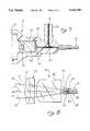
- FIG. 3is an enlarged, fragmentary, axial sectional view through a distal region of the endoscope and illustrating rays from an object being directed by a GRIN objective to a curved image plane.
- FIG. 4is a schematic view showing how the field curvature of the GRIN objective provides a curved image plane which would create out of focus regions if an image guide with a flat end face were utilized.
- FIG. 5is a schematic side elevational view partially in section of the GRIN objective and distal regions of the image guide of this invention.
- FIG. 6is a view similar to FIG. 5 illustrating an objective which includes multiple refracting elements rather than a GRIN rod.
- FIG. 7is an axial sectional view through a proximal region of the endoscope.
- FIG. 8is a ray tracing for the eyepiece optics.
- FIG. 1shows an endoscope 11 which generally comprises an endoscope body 13 and various optical components described below.
- the endoscope body 13includes an elongated, tubular cylindrical sheath 15 and an eyepiece housing 17 attached to the sheath.
- the sheath 15may be flexible or rigid, in this embodiment, the sheath 15 is rigid and is constructed of a rigid polymeric material or a suitable metal, such as stainless steel.
- the sheath 15is suitably attached to the eyepiece housing 17 in any suitable conventional manner.
- the features of this inventionare applicable to endoscopes for industrial uses, in the illustrated embodiment of the invention, the endoscope is adapted for medical use such as laparoscopy or arthroscopy.
- the endoscope 11includes illumination optics in the form of illumination optical fibers 19 which extend from a distal end 21 of the endoscope body 13 through the sheath and a light cable connector 23 (FIGS. 1 and 7) of the eyepiece housing 17.
- the connector 23is adapted to be coupled a source of illumination (not shown) so that light can be transmitted by the optical fibers 19 to the distal end 21 of the endoscope body 13 to illuminate the field of view.
- the optical componentsalso include an objective 25 (FIGS. 2 and 3) which has a distal end 26 and which is carried by the endoscope body 13 adjacent the distal end 21 and an elongated fiberoptic image guide 27 in the endoscope body for transmitting an image proximally.
- the image guide 27extends completely through the sheath 15 and terminates in the eyepiece housing 17 (FIG. 7).
- the image guide 27comprises a coherent bundle of optical fibers 29 which are shown somewhat schematically in FIGS. 3, 5 and 6. Each of the fibers 29 is capable of transmitting or relaying a portion or pixel of an image such that the combined output of the image guide is an image.
- An index matching medium in the form of an index matching adhesive or optical adhesive 31is employed at an interface 33 between the objective 25 and the image guide 27 to adhere the objective to the image guide.
- a bushing 35 having a passage 37receives the objective 25 and a distal portion of the image guide 27.
- the objective 25 and the distal portion of the image guide 27are coupled to the bushing by a suitable adhesive.
- the bushing 35is generally coaxial with the sheath 15 (FIG. 2) and the illumination optical fibers 19 are arranged in an annulus around the bushing.
- FIG. 4shows schematically parallel rays 41 and parallel rays 43 similar to rays emanating from an object a infinity which strike the distal surface 26a of the objective 25a in two different directions.
- the parallel rays 43are directed to a focus 47 and the parallel rays 41 are directed to a focus 49.
- the image guide 27aengages the objective 25a at an interface 33a.
- the focus 47is substantially at the interface 33a; however, the focus 49 is displaced proximally from the interface 33a.
- the objective 25 of this inventionhas a curved proximal surface 51 and the image guide has a curved distal end surface 53 with these two curved surfaces being in substantial engagement and substantially conforming to each other in shape.
- the surfaces 51 and 53are curved in two planes and are generally spherical.
- the surfaces 51 and 53may be of an aspherical shape.
- the focal points 47 and 49 for parallel rays 43 and 41, respectively, from an object 54are substantially at the interface 33 and may lie on the curved proximal surface 51.
- the objective 25provides a curved image plane substantially at the interface 33.
- the image planehas a shape which substantially conforms to the shape of the curved proximal surface of the objective and in this embodiment is substantially spherical. Consequently, all points of the image transmitted by the image guide 27 are in focus.
- the rays 41do not appear parallel to each other and the same is true for the rays 43. This is because the object 54 is not at infinity and because FIG. 3 is of necessity out of scale in that the distance from the distal end 21 to the object 54 is many times the diameter of the objective 25. For objects closer than infinity, the nonparallel rays will still form a curved image plane.
- the objective 25is in the form of a GRIN rod.
- the objective 25may have a refractive index of about 1.6 to about 1.7 and the optical fibers 29 of the image guide 27 may have a refractive index of about 1.53 to about 1.65.
- the index matching adhesive 31may have a refractive index of about 1.45 to about 1.7 to thereby greatly reduce refraction at the interface 33 and to reduce the likelihood that the image transmitted by the image guide 27 will have dark peripheral regions.
- the index matching adhesive 31is very thin and may be of the order of no greater than 0.002 inch with a thickness of no greater than about 0.001 inch being preferred. Consequently, an image plane which is substantially at the very thin interface 33 is within the depth of focus of the optics.
- each of the optical fibers 29terminates in an end face 55 at the curved distal end surface 53.
- the optical fibers 29 at the interface 33are substantially parallel, and moreover the optical fibers 29 may be substantially parallel throughout the full length of the image guide 27.
- each of the end faces 55generally conforms in shape to a confronting region of the curved proximal surface 51 of the objective 25.
- Those end faces 55 near the periphery of the image guide 27form acute angle with the longitudinal axis of the associated fiber 29. If an air gap existed at the interface 33 between an angled end face 55 near the periphery of the image guide 27 and the objective 25, the periphery of the image would appear dark at the proximal end of the image guide 27. This is due to refraction at the periphery of the interface 33 causing the light to deviate outside the acceptance angle of the individual fibers 29.
- the index matching adhesive 35covers the entire interface 33 between the curved proximal surface 51 and the curved distal end surface 53.
- a GRIN rodis used for the objective 25 and it provides a convex image plane as viewed in either axial or radial cross section.
- the image planeforms a portion of a sphere.
- FIG. 6illustrates that the objective 25b may comprise a plurality of refractive optical elements such as lenses 57, 59 and 61 and that the image plane at the interface 33b may be concave.
- the embodiment of FIG. 6corresponding to portions of the embodiment of FIG. 5 are designated by corresponding reference numerals followed by the letter "b".
- the embodiment of FIG. 6is identical to the embodiment of FIG. 5 in all respects not shown or described herein.
- the objective 25bmay of conventional construction, and in that regard the distal lens 57 may be a plano convex lens, the intermediate lens 59 may be a double convex lens and the proximal lens 61 may be concavo-convex.
- the lenses 57, 59 and 61are suitably adhered within the bushing 35b.
- the objective 25bfocuses the rays 41 and 43 at the focuses 49b and 47b, respectively, as described above in connection with the FIG. 5.
- the proximal lens 61has a curved proximal surface 51b on which all of the focal points or focuses from all of the rays incident upon the distal lens 57 fall such that the concave image plane lies substantially along and substantially conforms to the shape of the curved proximal surface 51b.
- the image guide 27bhas a curved distal end surface 53b in close proximity to the curved proximal surface 51b to provide the interface 33b and shape of these curved surfaces are substantially in conformity.
- the embodiment of FIG. 6is identical to the embodiment of FIG. 5 except for the multiple optical component objective 25b, the shape of the surfaces 51b and 53b and the shape of the interface 33b.
- the image formed at the image plane along the interface 33is transmitted by the image guide 27 proximally to a proximal end surface 71 (FIG. 7 and 8) of the image guide.
- Eyepiece optics 73(FIGS. 7 and 8) are carried by the eyepiece housing 17.
- the proximal end surface 71 of the image guide 27forms an object plane for the eyepiece optics 73, and the eyepiece optics 73 transmit an image of the object at the object plane proximally to an eye cup 75 for direct viewing by the user of the endoscope 11.
- the eyepiece optics 73may direct the image of the object to suitable camera for enabling the image to be viewed on a T.V. monitor.
- the eyepiece optics 73 in this embodimentalso introduce field curvature into the optical system, and this field curvature is accommodated by this invention in much the same manner as described above for the field curvature introduced by the objective 25.
- Optical systemscan be analyzed by considering rays of illumination moving through the system in either direction.
- the eyepiece optics 73For purposes of understanding the field of curvature introduced by the eyepiece optics 73, it is convenient to consider parallel rays 77 and a second group of parallel rays 79 being transmitted through the eyepiece optics 73 in a reverse direction, from left to right as viewed in FIG. 8. From FIG. 8 it can be seen that the eyepiece optics bring the parallel rays 77 at a focus 81 and bring the parallel rays 79 at a focus 83.
- the focuses 81 and 83along with similar focuses from other rays (not shown) define a concavely curved object plane which is substantially at a proximal interface 85 between the proximal end surface 71 and a curved distal surface 87 of the eyepiece optics.
- the proximal end surface 71 of the image guideis curved concavely and substantially conforms to the shape of the curved distal surface 87.
- the surfaces 71 and 87 and the object planeare curved in two planes and are part spherical.
- An index matching medium in the form of an index matching adhesive 89fully covers the proximal interface 85 and contacts the curved surfaces 71 and 87 to reduce refraction at the proximal interface. All other factors regarding the thickness and index of refraction of the index matching adhesive discussed above for the index matching adhesive 31 are applicable to the index matching adhesive 89, and like the surfaces 51 and 52, the surface 71 and 87 are in close proximity and preferably in substantial contact being spaced only by the very thin layer of the index matching adhesive 89 which holds them together. Thus, all of the teachings set forth above with respect to the surfaces 51 and 53, the interface 33 and the adhesive 31 are equally applicable to the surfaces 71 and 87, the adhesive 89 and the proximal interface 85.
- the eyepiece opticscan transmit an image of an object at the curved object plane which lies substantially along the proximal interface 85.
- the rays emanating from each point of the object planee.g. the focuses 81 and 83, are parallel as they leave a proximal surface 91 of the eyepiece optics 73.
- the eyepiece optics 73converts the curved object at the curved object plane to a flat image.
- the eyepiece optics 73include a proximal plano convex lens 93 which has its convex surface forming the curved distal surface 87 and a plano convex intermediate lens 95.
- the eyepiece optics 73also includes an doublet 97 which provides the proximal surface 91.
- the lenses 93, 95 and 97may be mounted in the eyepiece housing 17 in any suitable manner. For example, the lens 93 is adhered to the image guide 27 by the index matching adhesive 89 and the lenses 95 and 97 may be adhered to the eyepiece housing 17.
- the connector 23is coupled to a source of illumination (not shown) and the sheath 15 is inserted into a passage that is to be examined.
- the passagemay be in machinery or within a human or animal body.
- the objective 25provides a curved image plane substantially at the curved interface 33 and the image guide 27 transmits the image at the curved image plane proximally to the curved object plane at the proximal interface 85.
- the eyepiece optics 73transmits an image of the object at the curved object plane proximally for direct viewing.
Landscapes
- Physics & Mathematics (AREA)
- Health & Medical Sciences (AREA)
- Life Sciences & Earth Sciences (AREA)
- Optics & Photonics (AREA)
- Surgery (AREA)
- General Physics & Mathematics (AREA)
- Heart & Thoracic Surgery (AREA)
- Animal Behavior & Ethology (AREA)
- Pathology (AREA)
- Radiology & Medical Imaging (AREA)
- Veterinary Medicine (AREA)
- Engineering & Computer Science (AREA)
- Nuclear Medicine, Radiotherapy & Molecular Imaging (AREA)
- Molecular Biology (AREA)
- Medical Informatics (AREA)
- Biophysics (AREA)
- Biomedical Technology (AREA)
- General Health & Medical Sciences (AREA)
- Public Health (AREA)
- Astronomy & Astrophysics (AREA)
- Instruments For Viewing The Inside Of Hollow Bodies (AREA)
- Endoscopes (AREA)
Abstract
Description
Claims (18)
Priority Applications (3)
| Application Number | Priority Date | Filing Date | Title |
|---|---|---|---|
| US08/289,941US5630788A (en) | 1994-08-12 | 1994-08-12 | Endoscope with curved end image guide |
| AU33228/95AAU3322895A (en) | 1994-08-12 | 1995-08-11 | Endoscope with curved end image guide |
| PCT/US1995/010259WO1996004838A1 (en) | 1994-08-12 | 1995-08-11 | Endoscope with curved end image guide |
Applications Claiming Priority (1)
| Application Number | Priority Date | Filing Date | Title |
|---|---|---|---|
| US08/289,941US5630788A (en) | 1994-08-12 | 1994-08-12 | Endoscope with curved end image guide |
Publications (1)
| Publication Number | Publication Date |
|---|---|
| US5630788Atrue US5630788A (en) | 1997-05-20 |
Family
ID=23113840
Family Applications (1)
| Application Number | Title | Priority Date | Filing Date |
|---|---|---|---|
| US08/289,941Expired - LifetimeUS5630788A (en) | 1994-08-12 | 1994-08-12 | Endoscope with curved end image guide |
Country Status (3)
| Country | Link |
|---|---|
| US (1) | US5630788A (en) |
| AU (1) | AU3322895A (en) |
| WO (1) | WO1996004838A1 (en) |
Cited By (34)
| Publication number | Priority date | Publication date | Assignee | Title |
|---|---|---|---|---|
| US5951463A (en)* | 1998-03-18 | 1999-09-14 | Clarus Medical Systems, Inc. | Hand-held endoscopic viewing system |
| US5976077A (en)* | 1996-08-06 | 1999-11-02 | Olympus Winter & Ibe Gmbh | Surgical endoscopic instrument |
| US6006001A (en)* | 1996-12-02 | 1999-12-21 | The Research Foundation Of Cuny | Fiberoptic assembly useful in optical spectroscopy |
| US6038079A (en)* | 1997-10-09 | 2000-03-14 | Imagyn Medical Technologies, Inc. | Sapphire objective system |
| US6332092B1 (en) | 1998-07-08 | 2001-12-18 | Lifespex, Incorporated | Optical probe having and methods for uniform light irradiation and/or light collection over a volume |
| US20020097959A1 (en)* | 2001-01-19 | 2002-07-25 | Optosys Sa | Optical device |
| US6470124B1 (en)* | 1998-09-15 | 2002-10-22 | Assistance Publique - Hopitaux De Paris | Device for observation inside a body providing improved quality of observation |
| US6487440B2 (en) | 1998-07-08 | 2002-11-26 | Lifespex, Inc. | Optical probe having and methods for difuse and uniform light irradiation |
| US6498884B1 (en)* | 1999-10-21 | 2002-12-24 | Quickie Vision Llc | Wide-view endoscope compatible with HDTV format |
| US20030083552A1 (en)* | 2001-10-19 | 2003-05-01 | Visionscope, Inc. | Miniature endoscope with imaging fiber system |
| US6614957B2 (en)* | 2000-12-08 | 2003-09-02 | Science Applications International Corporation | Optical configuration for improved lens performance |
| US20030220574A1 (en)* | 2002-03-18 | 2003-11-27 | Sarcos Investments Lc. | Miniaturized imaging device including utility aperture and SSID |
| US20030222325A1 (en)* | 2002-03-18 | 2003-12-04 | Sarcos Investments Lc. | Miniaturized imaging device with integrated circuit connector system |
| US20050283048A1 (en)* | 2001-10-19 | 2005-12-22 | Visionscope, Llc | Portable imaging system employing a miniature endoscope |
| US20060146172A1 (en)* | 2002-03-18 | 2006-07-06 | Jacobsen Stephen C | Miniaturized utility device having integrated optical capabilities |
| US20070167681A1 (en)* | 2001-10-19 | 2007-07-19 | Gill Thomas J | Portable imaging system employing a miniature endoscope |
| US20080064925A1 (en)* | 2001-10-19 | 2008-03-13 | Gill Thomas J | Portable imaging system employing a miniature endoscope |
| US20080304143A1 (en)* | 2007-06-05 | 2008-12-11 | Jacobsen Stephen C | Mini-scope for multi-directional imaging |
| US20090147076A1 (en)* | 2007-12-10 | 2009-06-11 | Hasan Ertas | Wide angle HDTV endoscope |
| US20090180197A1 (en)* | 2008-01-11 | 2009-07-16 | Sterling Lc | Grin lens microscope system |
| US20090287048A1 (en)* | 2008-05-16 | 2009-11-19 | Sterling Lc | Method and apparatus for imaging within a living body |
| US20110141759A1 (en)* | 2009-12-10 | 2011-06-16 | Smith Ronald T | Multi-spot laser surgical probe using faceted optical elements |
| US8317689B1 (en) | 1999-09-13 | 2012-11-27 | Visionscope Technologies Llc | Miniature endoscope system |
| US20130003196A1 (en)* | 2011-06-29 | 2013-01-03 | Microsoft Corporation | Non-planar focal surface lens assembly |
| US8486735B2 (en) | 2008-07-30 | 2013-07-16 | Raytheon Company | Method and device for incremental wavelength variation to analyze tissue |
| US8614768B2 (en) | 2002-03-18 | 2013-12-24 | Raytheon Company | Miniaturized imaging device including GRIN lens optically coupled to SSID |
| DE102012108424A1 (en)* | 2012-09-10 | 2014-03-13 | Institut für Mess- und Regelungstechnik der Leibniz Universität Hannover | Optical system for endoscopic applications, has image interface that is oriented parallel to object interface with surface geometry and is oriented orthogonally to optical axis of gradient index (GRIN) lens |
| US8690762B2 (en) | 2008-06-18 | 2014-04-08 | Raytheon Company | Transparent endoscope head defining a focal length |
| US8717428B2 (en) | 2009-10-01 | 2014-05-06 | Raytheon Company | Light diffusion apparatus |
| US8828028B2 (en) | 2009-11-03 | 2014-09-09 | Raytheon Company | Suture device and method for closing a planar opening |
| US9060704B2 (en) | 2008-11-04 | 2015-06-23 | Sarcos Lc | Method and device for wavelength shifted imaging |
| US9144664B2 (en) | 2009-10-01 | 2015-09-29 | Sarcos Lc | Method and apparatus for manipulating movement of a micro-catheter |
| US9308128B2 (en) | 2013-01-08 | 2016-04-12 | Novartis Ag | Multi-spot laser probe with micro-structured faceted proximal surface |
| US9661996B2 (en) | 2009-10-01 | 2017-05-30 | Sarcos Lc | Needle delivered imaging device |
Families Citing this family (2)
| Publication number | Priority date | Publication date | Assignee | Title |
|---|---|---|---|---|
| DE202005012626U1 (en)* | 2005-05-19 | 2006-09-28 | Liebherr-Hausgeräte Ochsenhausen GmbH | Adjustable foot unit of a household appliance |
| DE102009008747B4 (en)* | 2009-02-13 | 2012-02-16 | Carl Zeiss Ag | Optical imaging system |
Citations (23)
| Publication number | Priority date | Publication date | Assignee | Title |
|---|---|---|---|---|
| US3666347A (en)* | 1969-03-17 | 1972-05-30 | Nippon Selfoc Kk Also Known As | Spherical lens structures |
| US4101196A (en)* | 1975-08-30 | 1978-07-18 | Olympus Optical Co., Ltd. | Objective optical system for endoscopes |
| SU625180A1 (en)* | 1977-04-25 | 1978-09-25 | Предприятие П/Я Р-6681 | All-round view objective |
| US4290667A (en)* | 1976-02-03 | 1981-09-22 | International Standard Electric Corporation | Optical fibre terminations and connectors |
| US4457590A (en)* | 1982-01-11 | 1984-07-03 | Corning Glass Works | Spherical gradient-index lens designs for video-disk pickup lens or the like |
| US4487646A (en)* | 1983-12-05 | 1984-12-11 | The United States Of America As Represented By The Secretary Of The Navy | Method for positioning the ends of fibres in a fibre optic array |
| US4529267A (en)* | 1980-12-10 | 1985-07-16 | Olympus Optical Co., Ltd. | Illuminating system for endoscopes |
| US4577926A (en)* | 1983-09-30 | 1986-03-25 | International Business Machines Corporation | Fiber optic writing head |
| US4650279A (en)* | 1984-08-15 | 1987-03-17 | The Charles Stark Draper Laboratory, Inc. | Fiber optic lens |
| US4684221A (en)* | 1985-01-16 | 1987-08-04 | Olympus Optical Co., Ltd. | Graded refractive index single lens system |
| US4721369A (en)* | 1985-09-18 | 1988-01-26 | Canon Kabushiki Kaisha | Gradient index single lens |
| US4755029A (en)* | 1986-05-22 | 1988-07-05 | Olympus Optical Co., Ltd. | Objective for an endoscope |
| US4762120A (en)* | 1983-11-08 | 1988-08-09 | Laserscope, Inc. | Endoscopic device having handle assembly and catheter assembly |
| US4772105A (en)* | 1985-04-18 | 1988-09-20 | Olympus Optical Co., Ltd. | Graded refractive index lens system |
| US4867521A (en)* | 1984-08-20 | 1989-09-19 | British Telecommunications Public Limited Company | Microlens manufacture |
| US4874220A (en)* | 1987-02-17 | 1989-10-17 | Asahi Kogaku Kogyo Kabushiki Kaisha | Viewing optical system for use with endoscope |
| US5029963A (en)* | 1990-02-15 | 1991-07-09 | Itt Corporation | Replacement device for a driver's viewer |
| SU1663597A1 (en)* | 1989-08-16 | 1991-07-15 | Предприятие П/Я Р-6681 | Input part of endoscope |
| US5125064A (en)* | 1991-04-22 | 1992-06-23 | Itt Corporation | Optical system using fiber optic element for field curvature reversal |
| US5172272A (en)* | 1989-12-25 | 1992-12-15 | Olympus Optical Co., Ltd. | Imaging lens system |
| US5279280A (en)* | 1991-10-18 | 1994-01-18 | Imagyn Medical, Inc. | Endoscope with grooved outer surface |
| US5299272A (en)* | 1993-01-27 | 1994-03-29 | Origin Medststems, Inc. | Method for attaching a gradient index lens to an optical fibre in the course of making an optical instrument |
| US5311611A (en)* | 1993-05-04 | 1994-05-10 | Ail Systems, Inc. | Imaging ball lens optically immersed with a fiber optic faceplate |
Family Cites Families (1)
| Publication number | Priority date | Publication date | Assignee | Title |
|---|---|---|---|---|
| US5270280A (en)* | 1990-11-01 | 1993-12-14 | Nippon Carbon Co., Ltd. | Packing material for liquid chromatography and method of manufacturing thereof |
- 1994
- 1994-08-12USUS08/289,941patent/US5630788A/ennot_activeExpired - Lifetime
- 1995
- 1995-08-11AUAU33228/95Apatent/AU3322895A/ennot_activeAbandoned
- 1995-08-11WOPCT/US1995/010259patent/WO1996004838A1/enactiveApplication Filing
Patent Citations (23)
| Publication number | Priority date | Publication date | Assignee | Title |
|---|---|---|---|---|
| US3666347A (en)* | 1969-03-17 | 1972-05-30 | Nippon Selfoc Kk Also Known As | Spherical lens structures |
| US4101196A (en)* | 1975-08-30 | 1978-07-18 | Olympus Optical Co., Ltd. | Objective optical system for endoscopes |
| US4290667A (en)* | 1976-02-03 | 1981-09-22 | International Standard Electric Corporation | Optical fibre terminations and connectors |
| SU625180A1 (en)* | 1977-04-25 | 1978-09-25 | Предприятие П/Я Р-6681 | All-round view objective |
| US4529267A (en)* | 1980-12-10 | 1985-07-16 | Olympus Optical Co., Ltd. | Illuminating system for endoscopes |
| US4457590A (en)* | 1982-01-11 | 1984-07-03 | Corning Glass Works | Spherical gradient-index lens designs for video-disk pickup lens or the like |
| US4577926A (en)* | 1983-09-30 | 1986-03-25 | International Business Machines Corporation | Fiber optic writing head |
| US4762120A (en)* | 1983-11-08 | 1988-08-09 | Laserscope, Inc. | Endoscopic device having handle assembly and catheter assembly |
| US4487646A (en)* | 1983-12-05 | 1984-12-11 | The United States Of America As Represented By The Secretary Of The Navy | Method for positioning the ends of fibres in a fibre optic array |
| US4650279A (en)* | 1984-08-15 | 1987-03-17 | The Charles Stark Draper Laboratory, Inc. | Fiber optic lens |
| US4867521A (en)* | 1984-08-20 | 1989-09-19 | British Telecommunications Public Limited Company | Microlens manufacture |
| US4684221A (en)* | 1985-01-16 | 1987-08-04 | Olympus Optical Co., Ltd. | Graded refractive index single lens system |
| US4772105A (en)* | 1985-04-18 | 1988-09-20 | Olympus Optical Co., Ltd. | Graded refractive index lens system |
| US4721369A (en)* | 1985-09-18 | 1988-01-26 | Canon Kabushiki Kaisha | Gradient index single lens |
| US4755029A (en)* | 1986-05-22 | 1988-07-05 | Olympus Optical Co., Ltd. | Objective for an endoscope |
| US4874220A (en)* | 1987-02-17 | 1989-10-17 | Asahi Kogaku Kogyo Kabushiki Kaisha | Viewing optical system for use with endoscope |
| SU1663597A1 (en)* | 1989-08-16 | 1991-07-15 | Предприятие П/Я Р-6681 | Input part of endoscope |
| US5172272A (en)* | 1989-12-25 | 1992-12-15 | Olympus Optical Co., Ltd. | Imaging lens system |
| US5029963A (en)* | 1990-02-15 | 1991-07-09 | Itt Corporation | Replacement device for a driver's viewer |
| US5125064A (en)* | 1991-04-22 | 1992-06-23 | Itt Corporation | Optical system using fiber optic element for field curvature reversal |
| US5279280A (en)* | 1991-10-18 | 1994-01-18 | Imagyn Medical, Inc. | Endoscope with grooved outer surface |
| US5299272A (en)* | 1993-01-27 | 1994-03-29 | Origin Medststems, Inc. | Method for attaching a gradient index lens to an optical fibre in the course of making an optical instrument |
| US5311611A (en)* | 1993-05-04 | 1994-05-10 | Ail Systems, Inc. | Imaging ball lens optically immersed with a fiber optic faceplate |
Non-Patent Citations (2)
| Title |
|---|
| Third European Conference on Optical Communication, Sep. 1977, "A Luneberg Lens for the Efficient Coupling of Laser Diode and a Graded-Index Fiber", pp. 176-178. |
| Third European Conference on Optical Communication, Sep. 1977, A Luneberg Lens for the Efficient Coupling of Laser Diode and a Graded Index Fiber , pp. 176 178.* |
Cited By (61)
| Publication number | Priority date | Publication date | Assignee | Title |
|---|---|---|---|---|
| US5976077A (en)* | 1996-08-06 | 1999-11-02 | Olympus Winter & Ibe Gmbh | Surgical endoscopic instrument |
| US6006001A (en)* | 1996-12-02 | 1999-12-21 | The Research Foundation Of Cuny | Fiberoptic assembly useful in optical spectroscopy |
| US6038079A (en)* | 1997-10-09 | 2000-03-14 | Imagyn Medical Technologies, Inc. | Sapphire objective system |
| US5951463A (en)* | 1998-03-18 | 1999-09-14 | Clarus Medical Systems, Inc. | Hand-held endoscopic viewing system |
| US6332092B1 (en) | 1998-07-08 | 2001-12-18 | Lifespex, Incorporated | Optical probe having and methods for uniform light irradiation and/or light collection over a volume |
| US6487440B2 (en) | 1998-07-08 | 2002-11-26 | Lifespex, Inc. | Optical probe having and methods for difuse and uniform light irradiation |
| US6470124B1 (en)* | 1998-09-15 | 2002-10-22 | Assistance Publique - Hopitaux De Paris | Device for observation inside a body providing improved quality of observation |
| US8317689B1 (en) | 1999-09-13 | 2012-11-27 | Visionscope Technologies Llc | Miniature endoscope system |
| US6498884B1 (en)* | 1999-10-21 | 2002-12-24 | Quickie Vision Llc | Wide-view endoscope compatible with HDTV format |
| US6614957B2 (en)* | 2000-12-08 | 2003-09-02 | Science Applications International Corporation | Optical configuration for improved lens performance |
| US20020097959A1 (en)* | 2001-01-19 | 2002-07-25 | Optosys Sa | Optical device |
| US6654519B2 (en)* | 2001-01-19 | 2003-11-25 | Optosys Sa | Optical device |
| US20070167681A1 (en)* | 2001-10-19 | 2007-07-19 | Gill Thomas J | Portable imaging system employing a miniature endoscope |
| US10595710B2 (en) | 2001-10-19 | 2020-03-24 | Visionscope Technologies Llc | Portable imaging system employing a miniature endoscope |
| US6863651B2 (en)* | 2001-10-19 | 2005-03-08 | Visionscope, Llc | Miniature endoscope with imaging fiber system |
| US20050283048A1 (en)* | 2001-10-19 | 2005-12-22 | Visionscope, Llc | Portable imaging system employing a miniature endoscope |
| US20060015014A1 (en)* | 2001-10-19 | 2006-01-19 | Paul Remijan | Miniature endoscope with imaging fiber system |
| US7942814B2 (en) | 2001-10-19 | 2011-05-17 | Visionscope Technologies Llc | Miniature endoscope with imaging fiber system |
| US8038602B2 (en)* | 2001-10-19 | 2011-10-18 | Visionscope Llc | Portable imaging system employing a miniature endoscope |
| US20080064925A1 (en)* | 2001-10-19 | 2008-03-13 | Gill Thomas J | Portable imaging system employing a miniature endoscope |
| US11484189B2 (en) | 2001-10-19 | 2022-11-01 | Visionscope Technologies Llc | Portable imaging system employing a miniature endoscope |
| US20030083552A1 (en)* | 2001-10-19 | 2003-05-01 | Visionscope, Inc. | Miniature endoscope with imaging fiber system |
| US20120071721A1 (en)* | 2001-10-19 | 2012-03-22 | Paul Remijan | Disposable sheath for a miniature endoscope |
| US20080185672A1 (en)* | 2002-03-18 | 2008-08-07 | Jacobsen Stephen C | Miniaturized imaging device with integrated circuit connector system |
| US7591780B2 (en) | 2002-03-18 | 2009-09-22 | Sterling Lc | Miniaturized imaging device with integrated circuit connector system |
| US20030220574A1 (en)* | 2002-03-18 | 2003-11-27 | Sarcos Investments Lc. | Miniaturized imaging device including utility aperture and SSID |
| US7629659B2 (en) | 2002-03-18 | 2009-12-08 | Sterling Lc | Miniaturized imaging device with integrated circuit connector system |
| US7787939B2 (en)* | 2002-03-18 | 2010-08-31 | Sterling Lc | Miniaturized imaging device including utility aperture and SSID |
| US20030222325A1 (en)* | 2002-03-18 | 2003-12-04 | Sarcos Investments Lc. | Miniaturized imaging device with integrated circuit connector system |
| US20060146172A1 (en)* | 2002-03-18 | 2006-07-06 | Jacobsen Stephen C | Miniaturized utility device having integrated optical capabilities |
| US8614768B2 (en) | 2002-03-18 | 2013-12-24 | Raytheon Company | Miniaturized imaging device including GRIN lens optically coupled to SSID |
| US8358462B2 (en) | 2007-06-05 | 2013-01-22 | Jacobsen Stephen C | Mini-scope for multi-directional imaging |
| US7835074B2 (en) | 2007-06-05 | 2010-11-16 | Sterling Lc | Mini-scope for multi-directional imaging |
| US20080304143A1 (en)* | 2007-06-05 | 2008-12-11 | Jacobsen Stephen C | Mini-scope for multi-directional imaging |
| US20090147076A1 (en)* | 2007-12-10 | 2009-06-11 | Hasan Ertas | Wide angle HDTV endoscope |
| US8360964B2 (en)* | 2007-12-10 | 2013-01-29 | Stryker Corporation | Wide angle HDTV endoscope |
| US7969659B2 (en) | 2008-01-11 | 2011-06-28 | Sterling Lc | Grin lens microscope system |
| US20090180197A1 (en)* | 2008-01-11 | 2009-07-16 | Sterling Lc | Grin lens microscope system |
| US20090287048A1 (en)* | 2008-05-16 | 2009-11-19 | Sterling Lc | Method and apparatus for imaging within a living body |
| US8690762B2 (en) | 2008-06-18 | 2014-04-08 | Raytheon Company | Transparent endoscope head defining a focal length |
| US9521946B2 (en) | 2008-06-18 | 2016-12-20 | Sarcos Lc | Transparent endoscope head defining a focal length |
| US8486735B2 (en) | 2008-07-30 | 2013-07-16 | Raytheon Company | Method and device for incremental wavelength variation to analyze tissue |
| US9259142B2 (en) | 2008-07-30 | 2016-02-16 | Sarcos Lc | Method and device for incremental wavelength variation to analyze tissue |
| US9060704B2 (en) | 2008-11-04 | 2015-06-23 | Sarcos Lc | Method and device for wavelength shifted imaging |
| US9717418B2 (en) | 2008-11-04 | 2017-08-01 | Sarcos Lc | Method and device for wavelength shifted imaging |
| US9144664B2 (en) | 2009-10-01 | 2015-09-29 | Sarcos Lc | Method and apparatus for manipulating movement of a micro-catheter |
| US9661996B2 (en) | 2009-10-01 | 2017-05-30 | Sarcos Lc | Needle delivered imaging device |
| US8717428B2 (en) | 2009-10-01 | 2014-05-06 | Raytheon Company | Light diffusion apparatus |
| US8828028B2 (en) | 2009-11-03 | 2014-09-09 | Raytheon Company | Suture device and method for closing a planar opening |
| AU2010328437B2 (en)* | 2009-12-10 | 2015-01-22 | Alcon Inc. | Multi-spot laser surgical probe using faceted optical elements |
| US20110141759A1 (en)* | 2009-12-10 | 2011-06-16 | Smith Ronald T | Multi-spot laser surgical probe using faceted optical elements |
| US9572479B2 (en) | 2009-12-10 | 2017-02-21 | Alcon Research, Ltd. | Multi-spot laser surgical probe using faceted optical elements |
| US20170112573A1 (en)* | 2009-12-10 | 2017-04-27 | Alcon Research, Ltd. | Multi-spot laser surgical probe using faceted optical elements |
| CN102791213B (en)* | 2009-12-10 | 2015-01-21 | 爱尔康研究有限公司 | Multi-spot laser surgical probe using faceted optical elements |
| US8764261B2 (en)* | 2009-12-10 | 2014-07-01 | Alcon Research, Ltd. | Multi-spot laser surgical probe using faceted optical elements |
| EP2509525A4 (en)* | 2009-12-10 | 2013-08-14 | Alcon Res Ltd | MULTIPOINT LASER SURGICAL PROBE USING FACET OPTICAL ELEMENTS |
| US10660704B2 (en)* | 2009-12-10 | 2020-05-26 | Alcon Inc. | Multi-spot laser surgical probe using faceted optical elements |
| CN102791213A (en)* | 2009-12-10 | 2012-11-21 | 爱尔康研究有限公司 | Multi-spot laser surgical probe using faceted optical elements |
| US20130003196A1 (en)* | 2011-06-29 | 2013-01-03 | Microsoft Corporation | Non-planar focal surface lens assembly |
| DE102012108424A1 (en)* | 2012-09-10 | 2014-03-13 | Institut für Mess- und Regelungstechnik der Leibniz Universität Hannover | Optical system for endoscopic applications, has image interface that is oriented parallel to object interface with surface geometry and is oriented orthogonally to optical axis of gradient index (GRIN) lens |
| US9308128B2 (en) | 2013-01-08 | 2016-04-12 | Novartis Ag | Multi-spot laser probe with micro-structured faceted proximal surface |
Also Published As
| Publication number | Publication date |
|---|---|
| AU3322895A (en) | 1996-03-07 |
| WO1996004838A1 (en) | 1996-02-22 |
Similar Documents
| Publication | Publication Date | Title |
|---|---|---|
| US5630788A (en) | Endoscope with curved end image guide | |
| US5369525A (en) | Ring lens assembly for an optical viewing device | |
| US3944341A (en) | Wide-angle ophthalmoscope and fundus camera | |
| US5423312A (en) | Rigid endoscope having modified high refractive index tunnel rod for image transmission and method of manufacture thereof | |
| JPH0355943Y2 (en) | ||
| US5188092A (en) | Disposable rigid endoscope | |
| EP1019756B1 (en) | Sapphire objective system | |
| US7221522B2 (en) | Optical system for variable direction of view instrument | |
| US5396366A (en) | Endoscope apparatus | |
| US7160248B2 (en) | Optical device for viewing of cavernous and/or inaccessible spaces | |
| US5888193A (en) | Endoscope with curved optical axis | |
| CA2091190A1 (en) | Disposable endoscope employing positive and negative gradient index of refraction optical materials | |
| US5980453A (en) | Endoscope with low distortion | |
| JP2009532153A (en) | Endoscope protector and endoscope corresponding thereto | |
| US5263110A (en) | Imaging endoscope and endoscopic method employing phase conjugate imaging techniques | |
| US5665051A (en) | Endoscope with axially movable optical fiber guide to compensate changes in length | |
| US4969708A (en) | Fiberoptic endoscope | |
| US4776668A (en) | Image focusing ocular piece for a viewing scope including mechanism for accommodating differential expansion | |
| EP1519675A1 (en) | Optical device for endoscope | |
| JPH0743619A (en) | Stereo endoscope | |
| US6063024A (en) | Observation apparatus | |
| JP3386187B2 (en) | Rigid endoscope device | |
| JPH10123411A (en) | Optical system for fiberscope | |
| JP2934024B2 (en) | Coaxial illumination observation device | |
| EP0260856A2 (en) | Distortion corrected endoscope |
Legal Events
| Date | Code | Title | Description |
|---|---|---|---|
| AS | Assignment | Owner name:IMAGYN MEDICAL, INC., CALIFORNIA Free format text:ASSIGNMENT OF ASSIGNORS INTEREST;ASSIGNOR:WOKER, GARY M.;REEL/FRAME:007121/0823 Effective date:19940810 | |
| AS | Assignment | Owner name:IMAGYN MEDICAL, INC., CALIFORNIA Free format text:ASSIGNMENT OF ASSIGNORS INTEREST;ASSIGNOR:FORKNER, JOHN F.;REEL/FRAME:007269/0688 Effective date:19941215 | |
| AS | Assignment | Owner name:IMAGYN MEDICAL, INC., CALIFORNIA Free format text:MERGER;ASSIGNOR:IMAGYN MEDICAL, INC.;REEL/FRAME:008430/0739 Effective date:19970324 | |
| STCF | Information on status: patent grant | Free format text:PATENTED CASE | |
| AS | Assignment | Owner name:BT COMMERCIAL CORPORATION, ILLINOIS Free format text:SECURITY AGREEMENT;ASSIGNOR:IMAGYN MEDICAL, INC.;REEL/FRAME:008886/0739 Effective date:19971230 | |
| AS | Assignment | Owner name:BT COMMERICIAL CORPORATION, A DELAWARE CORPORATION Free format text:SECURITY AGREEMENT;ASSIGNOR:IMAGYN MEDICAL, INC., A DELAWARE CORPORATION;REEL/FRAME:010444/0289 Effective date:19991029 | |
| AS | Assignment | Owner name:BT COMMERCIAL CORPORATION, ILLINOIS Free format text:SECURITY AGREEMENT;ASSIGNORS:IMAGYN MEDICAL TECHNOLGIES CALIFORNIA, INC.;DACOMED CORPORATION;ALLSTATE MEDICAL PRODUCTS, INC.;AND OTHERS;REEL/FRAME:010395/0972 Effective date:19991029 | |
| FPAY | Fee payment | Year of fee payment:4 | |
| AS | Assignment | Owner name:JPMORGAN CHASE BANK, AS ADMINISTRATIVE AGENT, TEXA Free format text:SECURITY INTEREST;ASSIGNOR:CONMED CORPORATION;REEL/FRAME:014289/0859 Effective date:20020828 | |
| AS | Assignment | Owner name:IMAGYN MEDICAL, INC., CALIFORNIA Free format text:RELEASE OF SECURITY INTEREST;ASSIGNOR:BT COMMERICAL CORPORATION;REEL/FRAME:014357/0523 Effective date:20010705 | |
| AS | Assignment | Owner name:CONMED CORPORATION, NEW YORK Free format text:ASSIGNMENT OF ASSIGNORS INTEREST;ASSIGNOR:IMAGYN MEDICAL, INC.;REEL/FRAME:014373/0084 Effective date:20010706 | |
| FEPP | Fee payment procedure | Free format text:PAT HOLDER NO LONGER CLAIMS SMALL ENTITY STATUS, ENTITY STATUS SET TO UNDISCOUNTED (ORIGINAL EVENT CODE: STOL); ENTITY STATUS OF PATENT OWNER: LARGE ENTITY | |
| FPAY | Fee payment | Year of fee payment:8 | |
| REFU | Refund | Free format text:REFUND - PAYMENT OF MAINTENANCE FEE, 8TH YR, SMALL ENTITY (ORIGINAL EVENT CODE: R2552); ENTITY STATUS OF PATENT OWNER: LARGE ENTITY | |
| FPAY | Fee payment | Year of fee payment:12 |