US5630456A - Window blind cord winding apparatus - Google Patents
Window blind cord winding apparatusDownload PDFInfo
- Publication number
- US5630456A US5630456AUS08/646,385US64638596AUS5630456AUS 5630456 AUS5630456 AUS 5630456AUS 64638596 AUS64638596 AUS 64638596AUS 5630456 AUS5630456 AUS 5630456A
- Authority
- US
- United States
- Prior art keywords
- spool
- cord
- receiving cavity
- circular
- outer housing
- Prior art date
- Legal status (The legal status is an assumption and is not a legal conclusion. Google has not performed a legal analysis and makes no representation as to the accuracy of the status listed.)
- Expired - Fee Related
Links
- 238000004804windingMethods0.000titleclaimsabstractdescription20
- GGWBHVILAJZWKJ-UHFFFAOYSA-Ndimethyl-[[5-[2-[[1-(methylamino)-2-nitroethenyl]amino]ethylsulfanylmethyl]furan-2-yl]methyl]azanium;chlorideChemical compoundCl.[O-][N+](=O)C=C(NC)NCCSCC1=CC=C(CN(C)C)O1GGWBHVILAJZWKJ-UHFFFAOYSA-N0.000description3
- 208000027418Wounds and injuryDiseases0.000description1
- 230000006378damageEffects0.000description1
- 208000014674injuryDiseases0.000description1
- 238000000034methodMethods0.000description1
- 238000012986modificationMethods0.000description1
- 230000004048modificationEffects0.000description1
Images

Classifications
- E—FIXED CONSTRUCTIONS
- E06—DOORS, WINDOWS, SHUTTERS, OR ROLLER BLINDS IN GENERAL; LADDERS
- E06B—FIXED OR MOVABLE CLOSURES FOR OPENINGS IN BUILDINGS, VEHICLES, FENCES OR LIKE ENCLOSURES IN GENERAL, e.g. DOORS, WINDOWS, BLINDS, GATES
- E06B9/00—Screening or protective devices for wall or similar openings, with or without operating or securing mechanisms; Closures of similar construction
- E06B9/24—Screens or other constructions affording protection against light, especially against sunshine; Similar screens for privacy or appearance; Slat blinds
- E06B9/26—Lamellar or like blinds, e.g. venetian blinds
- E06B9/28—Lamellar or like blinds, e.g. venetian blinds with horizontal lamellae, e.g. non-liftable
- E06B9/30—Lamellar or like blinds, e.g. venetian blinds with horizontal lamellae, e.g. non-liftable liftable
- E06B9/32—Operating, guiding, or securing devices therefor
- E06B9/326—Details of cords, e.g. buckles, drawing knobs
Definitions
- the present inventionrelates to a window blind cord winding apparatus
- a window blind cordpresents a potential hazard to infants.
- An infantis attracted to a dangling window blind cord.
- the dangling cordswings back and forth, providing a source of interest and amusement.
- the infantcan be tangled in the cord. Infants have been injured when they fell with the cord wrapped around them. If the cord is wrapped around a sensitive area, such as the infant's neck, the injury can be fatal.
- the Rozon apparatusdiscloses a spool assembly which is capped by a retainer plate that extends across one face. This retainer serves to retain cord on the spool.
- the retaineris rotatable between a first or access position and a second or use position. In the access position a user is selectively provided with access to the interior of the spool through an elbow shaped opening. A pair of grip openings are provided. The user inserts his fingers into the grip openings in order to rotate the retainer to the access position.
- the cord bells at the free ends of the cordare removed.
- the cord endsare then threaded through a slot into the interior of the spool.
- the userthen turns the retainer to the access position and ties the two free ends of the cord to form a knot that is large enough that it resists the free ends of the cord being pulled through the slot.
- This mode of assemblyis not very convenient for the user.
- the knotis not a sufficient size, the knot will be pulled from the interior of the spool during use.
- the Rozon referencedoes contemplate use with a single window blind cord.
- a window blind cord winding apparatusthat includes an outer housing including a base plate and an outer sidewall that extends from the base plate to define a circular spool receiving cavity.
- a slotis provided through the outer sidewall, thereby providing access to the circular spool receiving cavity.
- a spoolis provided including a circular base plate and a sidewall that extends from the base plate to define a circular cord bell receiving cavity. The spool is rotatably mounted within the circular spool receiving cavity of the outer housing.
- a slotis provided through the sidewall thereby permitting access to the circular cord bell receiving cavity.
- the circular cord bell receiving cavityhas an inner surface with a gear profile.
- a closure capis engagable with the outer sidewall to enclose the outer housing.
- the closure caphas an exterior surface and an interior cavity.
- a shaftextends through the closure cap.
- the shafthas a first end extending into the interior cavity and a second end extending from the exterior surface.
- a gearis rotatably mounted to the first end of the shaft.
- a hand gripis secured to the second end of the shaft.
- FIG. 1is a side elevation view of a window blind cord winding apparatus constructed in accordance with the teachings of the present invention.
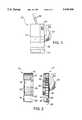
- FIG. 2is an exploded side elevation view, in section, of the window blind cord winding apparatus illustrated in FIG. 1.
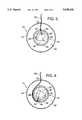
- FIG. 3is a right end elevation view, in section, of the window blind cord winding apparatus illustrated in FIG. 1.
- FIG. 4is a right end elevation view, in section, of the window blind cord winding apparatus illustrated in FIG. 1.
- FIG. 5is a left end elevation view, in section, of the window blind cord winding apparatus illustrated in FIG. 1.
- FIGS. 1 through 5The preferred embodiment, a window blind cord winding apparatus generally identified by reference numeral 10, will now be described with reference to FIGS. 1 through 5.
- window blind cord winding apparatus 10includes an outer housing 12 and a closure cap 14.
- outer housing 12includes a base plate 16 and an outer sidewall 18 that extends from base plate 16 to define a circular spool receiving cavity 20.
- a cord access slot 22is provided through outer sidewall 18 to provide access to circular spool receiving cavity 20.
- a spool 24is provided including a circular base plate 26 and a sidewall 28 that extends from base plate 26 to define a circular cord bell receiving cavity 30.
- spool 24is rotatably mounted by means of a rivet 32 within circular spool receiving cavity 20 of outer housing 12.
- a cord access slot 34is provided through sidewall 28 thereby providing access to circular cord bell receiving cavity 30.
- circular cord bell receiving cavity 30has an inner surface 36 with a gear profile 38.
- closure cap 14has an annular clamping flange 40. When closure cap 14 is placed onto outer housing 12, annular clamping flange 40 engages outer sidewall 18 to enclose outer housing 12.
- closure cap 14has an exterior surface 42 and an interior cavity 44.
- a shaft 46extends through closure cap 14. Shaft 46 has a first end 48 and a second end (not shown). First end 48 extends into interior cavity 44 and is secured to a gear 50. Referring to FIG. 2, the second end (not shown) extends from exterior surface 42 and is attached to a crank 52 that provides a hand grip for manipulation of shaft 46.
- a ratchet mechanism 54is used as means for locking spool 24 in a selected rotational position relative to outer housing 12.
- Ratchet mechanism 54includes a ratchet gear profile 56 which mates with a gear member 58 that is pivotally mounted within interior cavity 44 of closure cap 14.
- Gear member 58is pivotally movable between a locking position engaging ratchet gear profile 56 and a release position spaced from ratchet gear profile 56.
- a release button 60extends through closure cap 14. Release button 60 is accessible from exterior surface 42. When pressed it engages gear member 58 to pivot gear member 58 to the release position.
- window blind cord winding apparatus 10The use and operation of window blind cord winding apparatus 10 will now be described with reference to FIGS. 1 through 5.
- closure cap 14is removed to provide access to cord bell receiving cavity 30 of spool 24.
- window blind cords 62have a free end 64 on which is positioned a cord bell 66.
- Cord bell 66is positioned in circular cord bell receiving cavity 30.
- Cord 62is then extended through slot 34 in spool 24 and slot 22 in outer housing 12.
- Closure cap 14is then repositioned onto outer housing 12.
- gear 50engages gear profile 38 on inner surface 36 of bell receiving cavity 30 of spool 24.
- gear 50rotates engaging gear profile 38 to rotate spool 24.
- Ratchet mechanism 54maintains spool 24 in the selected rotational position. Ratchet mechanism 54 permits rotation of spool 24 is only one direction, namely, to wind more of cord 62 onto spool 24. When it is desired to release some cord, button 60 must be pushed to pivot gear member 58 to the release position in which spool 24 is free to rotate in the opposite direction.
- window blind cord winding apparatus 10the relative simplicity and ease of use provided by window blind cord winding apparatus 10.
- the userneed not temporarily remove, and thus risk losing the cord bells from their blinds.
- a dial, knob or the likecould be substituted for crank 52.
- other modificationsmay be made to the illustrated embodiment without departing from the spirit and scope of the invention as hereinafter defined in the Claims.
Landscapes
- Engineering & Computer Science (AREA)
- Structural Engineering (AREA)
- Architecture (AREA)
- Civil Engineering (AREA)
- Blinds (AREA)
Abstract
Description
The present invention relates to a window blind cord winding apparatus
A window blind cord presents a potential hazard to infants. An infant is attracted to a dangling window blind cord. The dangling cord swings back and forth, providing a source of interest and amusement. In the process of playing with the cord, however, the infant can be tangled in the cord. Infants have been injured when they fell with the cord wrapped around them. If the cord is wrapped around a sensitive area, such as the infant's neck, the injury can be fatal.
In order to reduce or eliminate the danger to infants window blind cord winding apparatus have been developed. An example of such a window blind cord winding apparatus is Canadian Patent Application 2,095,165 by Rozon published in 1993. The Rozon apparatus discloses a spool assembly which is capped by a retainer plate that extends across one face. This retainer serves to retain cord on the spool. The retainer is rotatable between a first or access position and a second or use position. In the access position a user is selectively provided with access to the interior of the spool through an elbow shaped opening. A pair of grip openings are provided. The user inserts his fingers into the grip openings in order to rotate the retainer to the access position. In order to attach the apparatus to a window blind having free cord ends, the cord bells at the free ends of the cord are removed. The cord ends are then threaded through a slot into the interior of the spool. The user then turns the retainer to the access position and ties the two free ends of the cord to form a knot that is large enough that it resists the free ends of the cord being pulled through the slot. This mode of assembly is not very convenient for the user. Furthermore, if the knot is not a sufficient size, the knot will be pulled from the interior of the spool during use. The Rozon reference does contemplate use with a single window blind cord.
What is required is a window blind cord winding apparatus that is easier to use and can be used with a single window blind cord.
According to the present invention there is provided a window blind cord winding apparatus that includes an outer housing including a base plate and an outer sidewall that extends from the base plate to define a circular spool receiving cavity. A slot is provided through the outer sidewall, thereby providing access to the circular spool receiving cavity. A spool is provided including a circular base plate and a sidewall that extends from the base plate to define a circular cord bell receiving cavity. The spool is rotatably mounted within the circular spool receiving cavity of the outer housing. A slot is provided through the sidewall thereby permitting access to the circular cord bell receiving cavity. The circular cord bell receiving cavity has an inner surface with a gear profile. A closure cap is engagable with the outer sidewall to enclose the outer housing. The closure cap has an exterior surface and an interior cavity. A shaft extends through the closure cap. The shaft has a first end extending into the interior cavity and a second end extending from the exterior surface. A gear is rotatably mounted to the first end of the shaft. A hand grip is secured to the second end of the shaft. When the closure cap is placed onto the outer housing the gear engages the gear profile on the inner surface of the cord bell receiving cavity of the spool. Upon the hand grip being used to rotate the shaft, the gear rotates engaging the gear profile to rotate the spool. Means is provided for locking the spool in a selected rotational position relative to the housing.
These and other features of the invention will become more apparent from the following description in which reference is made to the appended drawings, wherein:
FIG. 1 is a side elevation view of a window blind cord winding apparatus constructed in accordance with the teachings of the present invention.
FIG. 2 is an exploded side elevation view, in section, of the window blind cord winding apparatus illustrated in FIG. 1.
FIG. 3 is a right end elevation view, in section, of the window blind cord winding apparatus illustrated in FIG. 1.
FIG. 4 is a right end elevation view, in section, of the window blind cord winding apparatus illustrated in FIG. 1.
FIG. 5 is a left end elevation view, in section, of the window blind cord winding apparatus illustrated in FIG. 1.
The preferred embodiment, a window blind cord winding apparatus generally identified byreference numeral 10, will now be described with reference to FIGS. 1 through 5.
Referring to FIG. 1, window blindcord winding apparatus 10 includes anouter housing 12 and aclosure cap 14. Referring to FIGS. 2 through 4,outer housing 12 includes a base plate 16 and anouter sidewall 18 that extends from base plate 16 to define a circularspool receiving cavity 20. Acord access slot 22 is provided throughouter sidewall 18 to provide access to circularspool receiving cavity 20. Aspool 24 is provided including acircular base plate 26 and asidewall 28 that extends frombase plate 26 to define a circular cordbell receiving cavity 30. Referring to FIG. 2,spool 24 is rotatably mounted by means of arivet 32 within circularspool receiving cavity 20 ofouter housing 12. Acord access slot 34 is provided throughsidewall 28 thereby providing access to circular cordbell receiving cavity 30. Referring to FIGS. 3 and 4, circular cordbell receiving cavity 30 has aninner surface 36 with agear profile 38. Referring to FIG. 2,closure cap 14 has anannular clamping flange 40. Whenclosure cap 14 is placed ontoouter housing 12,annular clamping flange 40 engagesouter sidewall 18 to encloseouter housing 12. Referring to FIG. 2,closure cap 14 has anexterior surface 42 and aninterior cavity 44. Referring to FIG. 5, ashaft 46 extends throughclosure cap 14. Shaft 46 has a first end 48 and a second end (not shown). First end 48 extends intointerior cavity 44 and is secured to agear 50. Referring to FIG. 2, the second end (not shown) extends fromexterior surface 42 and is attached to acrank 52 that provides a hand grip for manipulation ofshaft 46. Whenclosure cap 14 is placed ontoouter housing 12gear 50 engagesgear profile 38 oninner surface 36 ofbell receiving cavity 30 ofspool 24. Referring to FIG. 5, aratchet mechanism 54 is used as means forlocking spool 24 in a selected rotational position relative toouter housing 12.Ratchet mechanism 54 includes aratchet gear profile 56 which mates with agear member 58 that is pivotally mounted withininterior cavity 44 ofclosure cap 14.Gear member 58 is pivotally movable between a locking position engagingratchet gear profile 56 and a release position spaced fromratchet gear profile 56. Arelease button 60 extends throughclosure cap 14.Release button 60 is accessible fromexterior surface 42. When pressed it engagesgear member 58 to pivotgear member 58 to the release position.
The use and operation of window blindcord winding apparatus 10 will now be described with reference to FIGS. 1 through 5. Referring to FIG. 2,closure cap 14 is removed to provide access to cordbell receiving cavity 30 ofspool 24. Referring to FIGS. 3 and 4, windowblind cords 62 have afree end 64 on which is positioned acord bell 66.Cord bell 66 is positioned in circular cordbell receiving cavity 30.Cord 62 is then extended throughslot 34 inspool 24 andslot 22 inouter housing 12.Closure cap 14 is then repositioned ontoouter housing 12. Whenclosure cap 14 is placed ontoouter housing 12gear 50 engagesgear profile 38 oninner surface 36 ofbell receiving cavity 30 ofspool 24. Upon crank 52 being rotated,gear 50 rotates engaginggear profile 38 to rotatespool 24. This windscord 62 aroundspool 24 in the manner illustrated in FIG. 4.Ratchet mechanism 54 maintainsspool 24 in the selected rotational position.Ratchet mechanism 54 permits rotation ofspool 24 is only one direction, namely, to wind more ofcord 62 ontospool 24. When it is desired to release some cord,button 60 must be pushed to pivotgear member 58 to the release position in whichspool 24 is free to rotate in the opposite direction.
It will be apparent to one skilled in the art the relative simplicity and ease of use provided by window blindcord winding apparatus 10. In addition, in order to useapparatus 10, the user need not temporarily remove, and thus risk losing the cord bells from their blinds. It will also be apparent to one skilled in that art that a dial, knob or the like could be substituted forcrank 52. It will finally be apparent to one skilled in the art that other modifications may be made to the illustrated embodiment without departing from the spirit and scope of the invention as hereinafter defined in the Claims.
Claims (3)
1. A window blind cord winding apparatus, comprising:
an outer housing having a circular spool receiving cavity with a cord access opening;
a spool positioned in the spool receiving cavity of the outer housing, the spool having a circular cord bell receiving cavity with an inner gear profile and a cord access opening;
a removable closure cap engagable with the outer housing, the closure cap having an exterior surface and an interior cavity, a shaft extending through the closure cap, the shaft having a first end extending into the interior cavity and a second end extending from the exterior surface, a gear being mounted to the first end of the shaft, a hand grip being secured to the second end of the shaft, the gear engaging the inner gear profile on the cord bell receiving cavity of the spool, whereby the hand grip is used to rotate the gear with the gear engaging the inner gear profile to rotate the spool; and
means for locking the spool in a selected rotational position relative to the outer housing.
2. A window blind cord winding apparatus, comprising:
an outer housing including a base plate and an outer sidewall that extends from the base plate to define a circular spool receiving cavity, a slot being provided through the outer sidewall, thereby providing access to the circular spool receiving cavity;
a spool including a circular base plate and a sidewall that extends from the base plate to define a circular cord bell receiving cavity, the spool being rotatably mounted within the circular spool receiving cavity of the outer housing, a slot being provided through the sidewall thereby providing access to the circular cord bell receiving cavity, the circular cord bell receiving cavity having an inner surface with a gear profile;
a closure cap engagable with the outer sidewall to enclose the outer housing, the closure cap having an exterior surface and an interior cavity, a shaft extending through the closure cap, the shaft having a first end extending into the interior cavity and a second end extending from the exterior surface, a gear being mounted to the first end of the shaft, a hand grip being secured to the second end of the shaft, when the closure cap is placed onto the outer housing the gear engages the gear profile on the inner surface of the cord bell receiving cavity of the spool, such that upon the hand grip being used to rotate the shaft, the gear rotates engaging the gear profile to rotate the spool; and
means for locking the spool in a selected rotational position relative to the outer housing.
3. In combination;
a window blind cord having a free end on which is positioned a cord bell;
a window blind cord winding apparatus, including:
an outer housing including a base plate and an outer sidewall that extends from the base plate to define a circular spool receiving cavity, a slot being provided through the outer sidewall, thereby providing access to the circular spool receiving cavity;
a spool including a circular base plate and a sidewall that extends from the base plate to define a circular cord bell receiving cavity, the spool being rotatably mounted within the circular spool receiving cavity of the outer housing, a slot being provided through the sidewall thereby providing access to the circular cord bell receiving cavity, the circular cord bell receiving cavity having an inner surface with a gear profile; and
a closure cap engagable with the outer sidewall to enclose the outer housing, the closure cap having an exterior surface and an interior cavity, a shaft extending through the closure cap, the shaft having a first end extending into the interior cavity and a second end extending from the exterior surface, a gear being mounted to the first end of the shaft, a hand grip being secured to the second end of the shaft, when the closure cap is placed onto the outer housing the gear engages the gear profile on the inner surface of the bell receiving cavity of the spool; and
means for locking the spool in a selected rotational position relative to the outer housing;
the cord bell being positioned in the circular cord bell receiving cavity, the cord being extended through the slot in the spool and the slot in the outer housing, such that upon the hand grip being used to rotate the shaft, the gear rotates engaging the gear profile to rotate the spool, thereby winding the cord around the spool.
Priority Applications (2)
| Application Number | Priority Date | Filing Date | Title |
|---|---|---|---|
| US08/646,385US5630456A (en) | 1996-05-08 | 1996-05-08 | Window blind cord winding apparatus |
| CA002204711ACA2204711A1 (en) | 1996-05-08 | 1997-05-07 | Window blind cord winding apparatus |
Applications Claiming Priority (1)
| Application Number | Priority Date | Filing Date | Title |
|---|---|---|---|
| US08/646,385US5630456A (en) | 1996-05-08 | 1996-05-08 | Window blind cord winding apparatus |
Publications (1)
| Publication Number | Publication Date |
|---|---|
| US5630456Atrue US5630456A (en) | 1997-05-20 |
Family
ID=24592838
Family Applications (1)
| Application Number | Title | Priority Date | Filing Date |
|---|---|---|---|
| US08/646,385Expired - Fee RelatedUS5630456A (en) | 1996-05-08 | 1996-05-08 | Window blind cord winding apparatus |
Country Status (2)
| Country | Link |
|---|---|
| US (1) | US5630456A (en) |
| CA (1) | CA2204711A1 (en) |
Cited By (43)
| Publication number | Priority date | Publication date | Assignee | Title |
|---|---|---|---|---|
| US5762281A (en)* | 1997-02-18 | 1998-06-09 | Foley; Michael | Automatically loading cord winder apparatus and method |
| US5791580A (en)* | 1997-03-24 | 1998-08-11 | Anderson; Dennis W. | Cord retraction device |
| US5918658A (en)* | 1997-12-17 | 1999-07-06 | Schartner; Elena E. | Retractable blind pull |
| US6152395A (en)* | 1998-05-29 | 2000-11-28 | Lippert Pintlepin Mfg. Inc. | Spool assembly for pintle |
| US6241174B1 (en)* | 1999-11-10 | 2001-06-05 | Constance F. Berger | Belt shortening device |
| US6398146B1 (en)* | 1999-06-09 | 2002-06-04 | Simbac S.P.A. | Device for maneuvering a shutter or roller-type closure member and process for manufacturing such a closure member |
| US6463986B1 (en) | 2001-04-10 | 2002-10-15 | William C. Gouda | Window treatment assembly pull-cord keeper |
| US6745969B1 (en) | 2003-01-03 | 2004-06-08 | New Spin Corporation | Pull-cord keeper |
| US6902029B2 (en)* | 2001-10-30 | 2005-06-07 | Owl Investors Of Texas, Llc | Retractable ear protection device |
| US20060065772A1 (en)* | 2004-09-27 | 2006-03-30 | Deka Products Limited Partnership | Infusion set improvements |
| US20110214258A1 (en)* | 2010-03-04 | 2011-09-08 | Kristi Lee Seymour | Safety device for corded window treatments |
| US20120116390A1 (en)* | 2010-11-05 | 2012-05-10 | Madan Ashvani K | Surgical instrument with ratcheting rotatable shaft |
| US20140360681A1 (en)* | 2013-06-07 | 2014-12-11 | Norbert Marocco | Venetian blind with cord retractor |
| US9000720B2 (en) | 2010-11-05 | 2015-04-07 | Ethicon Endo-Surgery, Inc. | Medical device packaging with charging interface |
| US8998939B2 (en) | 2010-11-05 | 2015-04-07 | Ethicon Endo-Surgery, Inc. | Surgical instrument with modular end effector |
| US9011471B2 (en) | 2010-11-05 | 2015-04-21 | Ethicon Endo-Surgery, Inc. | Surgical instrument with pivoting coupling to modular shaft and end effector |
| US9011427B2 (en) | 2010-11-05 | 2015-04-21 | Ethicon Endo-Surgery, Inc. | Surgical instrument safety glasses |
| US9017851B2 (en) | 2010-11-05 | 2015-04-28 | Ethicon Endo-Surgery, Inc. | Sterile housing for non-sterile medical device component |
| US9017849B2 (en) | 2010-11-05 | 2015-04-28 | Ethicon Endo-Surgery, Inc. | Power source management for medical device |
| US9089338B2 (en) | 2010-11-05 | 2015-07-28 | Ethicon Endo-Surgery, Inc. | Medical device packaging with window for insertion of reusable component |
| US9126802B2 (en) | 2012-04-30 | 2015-09-08 | Adc Telecommunications, Inc. | Payout spool with automatic cable disconnect/reconnect |
| US9161803B2 (en) | 2010-11-05 | 2015-10-20 | Ethicon Endo-Surgery, Inc. | Motor driven electrosurgical device with mechanical and electrical feedback |
| US9247986B2 (en) | 2010-11-05 | 2016-02-02 | Ethicon Endo-Surgery, Llc | Surgical instrument with ultrasonic transducer having integral switches |
| US20160032645A1 (en)* | 2014-07-31 | 2016-02-04 | Nien Made Enterprise Co., Ltd. | Adjustable cord locker and window blind having such adjustable cord locker |
| US9375255B2 (en) | 2010-11-05 | 2016-06-28 | Ethicon Endo-Surgery, Llc | Surgical instrument handpiece with resiliently biased coupling to modular shaft and end effector |
| US9381058B2 (en) | 2010-11-05 | 2016-07-05 | Ethicon Endo-Surgery, Llc | Recharge system for medical devices |
| US9421062B2 (en) | 2010-11-05 | 2016-08-23 | Ethicon Endo-Surgery, Llc | Surgical instrument shaft with resiliently biased coupling to handpiece |
| US9500831B2 (en) | 2012-04-30 | 2016-11-22 | Commscope Technologies Llc | Cable payout cassette with single layer cable storage area |
| US9526921B2 (en) | 2010-11-05 | 2016-12-27 | Ethicon Endo-Surgery, Llc | User feedback through end effector of surgical instrument |
| US9597143B2 (en) | 2010-11-05 | 2017-03-21 | Ethicon Endo-Surgery, Llc | Sterile medical instrument charging device |
| US9649150B2 (en) | 2010-11-05 | 2017-05-16 | Ethicon Endo-Surgery, Llc | Selective activation of electronic components in medical device |
| US9722407B2 (en) | 2012-04-30 | 2017-08-01 | Commscope Technologies Llc | Guided cable storage assembly with switchbacks |
| US9782215B2 (en) | 2010-11-05 | 2017-10-10 | Ethicon Endo-Surgery, Llc | Surgical instrument with ultrasonic transducer having integral switches |
| US9782214B2 (en) | 2010-11-05 | 2017-10-10 | Ethicon Llc | Surgical instrument with sensor and powered control |
| US9908742B2 (en)* | 2012-04-30 | 2018-03-06 | Commscope Technologies Llc | Cable storage spool with center feed |
| US10085792B2 (en) | 2010-11-05 | 2018-10-02 | Ethicon Llc | Surgical instrument with motorized attachment feature |
| US10136938B2 (en) | 2014-10-29 | 2018-11-27 | Ethicon Llc | Electrosurgical instrument with sensor |
| US20190321595A1 (en)* | 2018-04-20 | 2019-10-24 | Becton, Dickinson And Company | Instrument delivery device having a rotary element |
| US10537380B2 (en) | 2010-11-05 | 2020-01-21 | Ethicon Llc | Surgical instrument with charging station and wireless communication |
| US10660695B2 (en) | 2010-11-05 | 2020-05-26 | Ethicon Llc | Sterile medical instrument charging device |
| US10881448B2 (en) | 2010-11-05 | 2021-01-05 | Ethicon Llc | Cam driven coupling between ultrasonic transducer and waveguide in surgical instrument |
| US10959769B2 (en) | 2010-11-05 | 2021-03-30 | Ethicon Llc | Surgical instrument with slip ring assembly to power ultrasonic transducer |
| US10973563B2 (en) | 2010-11-05 | 2021-04-13 | Ethicon Llc | Surgical instrument with charging devices |
Citations (10)
| Publication number | Priority date | Publication date | Assignee | Title |
|---|---|---|---|---|
| US967601A (en)* | 1909-09-02 | 1910-08-16 | Thomas M Bovard | Clothes-line reel. |
| US1027655A (en)* | 1911-10-09 | 1912-05-28 | Cornelius Johnson | Clothes-line reel and stretcher. |
| US1089023A (en)* | 1913-01-29 | 1914-03-03 | Nick W Trautner | Clothes-line reel. |
| US2187458A (en)* | 1937-05-07 | 1940-01-16 | Fred E Lawson | Housing for venetian blind operating mechanism |
| US3044732A (en)* | 1959-08-13 | 1962-07-17 | Patrick W Simonds | Wrist reel |
| US3123130A (en)* | 1964-03-03 | Operating device for venetian blinds | ||
| US3465806A (en)* | 1968-04-19 | 1969-09-09 | Decor Specialties Inc | Pleated blind assembly |
| US4271893A (en)* | 1979-03-26 | 1981-06-09 | Mccluskey William A | Window blind cord control apparatus |
| CA2095165A1 (en)* | 1992-05-01 | 1993-11-02 | David Rozon | Retraction device for window blind cords |
| US5279473A (en)* | 1992-05-01 | 1994-01-18 | 2844788 Canada Ltee | Cord retraction device |
- 1996
- 1996-05-08USUS08/646,385patent/US5630456A/ennot_activeExpired - Fee Related
- 1997
- 1997-05-07CACA002204711Apatent/CA2204711A1/ennot_activeAbandoned
Patent Citations (10)
| Publication number | Priority date | Publication date | Assignee | Title |
|---|---|---|---|---|
| US3123130A (en)* | 1964-03-03 | Operating device for venetian blinds | ||
| US967601A (en)* | 1909-09-02 | 1910-08-16 | Thomas M Bovard | Clothes-line reel. |
| US1027655A (en)* | 1911-10-09 | 1912-05-28 | Cornelius Johnson | Clothes-line reel and stretcher. |
| US1089023A (en)* | 1913-01-29 | 1914-03-03 | Nick W Trautner | Clothes-line reel. |
| US2187458A (en)* | 1937-05-07 | 1940-01-16 | Fred E Lawson | Housing for venetian blind operating mechanism |
| US3044732A (en)* | 1959-08-13 | 1962-07-17 | Patrick W Simonds | Wrist reel |
| US3465806A (en)* | 1968-04-19 | 1969-09-09 | Decor Specialties Inc | Pleated blind assembly |
| US4271893A (en)* | 1979-03-26 | 1981-06-09 | Mccluskey William A | Window blind cord control apparatus |
| CA2095165A1 (en)* | 1992-05-01 | 1993-11-02 | David Rozon | Retraction device for window blind cords |
| US5279473A (en)* | 1992-05-01 | 1994-01-18 | 2844788 Canada Ltee | Cord retraction device |
Cited By (63)
| Publication number | Priority date | Publication date | Assignee | Title |
|---|---|---|---|---|
| US5762281A (en)* | 1997-02-18 | 1998-06-09 | Foley; Michael | Automatically loading cord winder apparatus and method |
| US5791580A (en)* | 1997-03-24 | 1998-08-11 | Anderson; Dennis W. | Cord retraction device |
| US5918658A (en)* | 1997-12-17 | 1999-07-06 | Schartner; Elena E. | Retractable blind pull |
| US6152395A (en)* | 1998-05-29 | 2000-11-28 | Lippert Pintlepin Mfg. Inc. | Spool assembly for pintle |
| US6398146B1 (en)* | 1999-06-09 | 2002-06-04 | Simbac S.P.A. | Device for maneuvering a shutter or roller-type closure member and process for manufacturing such a closure member |
| US6241174B1 (en)* | 1999-11-10 | 2001-06-05 | Constance F. Berger | Belt shortening device |
| US6463986B1 (en) | 2001-04-10 | 2002-10-15 | William C. Gouda | Window treatment assembly pull-cord keeper |
| US6902029B2 (en)* | 2001-10-30 | 2005-06-07 | Owl Investors Of Texas, Llc | Retractable ear protection device |
| US6745969B1 (en) | 2003-01-03 | 2004-06-08 | New Spin Corporation | Pull-cord keeper |
| US8500054B2 (en)* | 2004-09-27 | 2013-08-06 | Deka Products Limited Partnership | Infusion set improvements |
| US20060065772A1 (en)* | 2004-09-27 | 2006-03-30 | Deka Products Limited Partnership | Infusion set improvements |
| US20110214258A1 (en)* | 2010-03-04 | 2011-09-08 | Kristi Lee Seymour | Safety device for corded window treatments |
| US9364279B2 (en) | 2010-11-05 | 2016-06-14 | Ethicon Endo-Surgery, Llc | User feedback through handpiece of surgical instrument |
| US9526921B2 (en) | 2010-11-05 | 2016-12-27 | Ethicon Endo-Surgery, Llc | User feedback through end effector of surgical instrument |
| US9000720B2 (en) | 2010-11-05 | 2015-04-07 | Ethicon Endo-Surgery, Inc. | Medical device packaging with charging interface |
| US8998939B2 (en) | 2010-11-05 | 2015-04-07 | Ethicon Endo-Surgery, Inc. | Surgical instrument with modular end effector |
| US9011471B2 (en) | 2010-11-05 | 2015-04-21 | Ethicon Endo-Surgery, Inc. | Surgical instrument with pivoting coupling to modular shaft and end effector |
| US9011427B2 (en) | 2010-11-05 | 2015-04-21 | Ethicon Endo-Surgery, Inc. | Surgical instrument safety glasses |
| US9017851B2 (en) | 2010-11-05 | 2015-04-28 | Ethicon Endo-Surgery, Inc. | Sterile housing for non-sterile medical device component |
| US9017849B2 (en) | 2010-11-05 | 2015-04-28 | Ethicon Endo-Surgery, Inc. | Power source management for medical device |
| US9039720B2 (en)* | 2010-11-05 | 2015-05-26 | Ethicon Endo-Surgery, Inc. | Surgical instrument with ratcheting rotatable shaft |
| US9072523B2 (en) | 2010-11-05 | 2015-07-07 | Ethicon Endo-Surgery, Inc. | Medical device with feature for sterile acceptance of non-sterile reusable component |
| US9089338B2 (en) | 2010-11-05 | 2015-07-28 | Ethicon Endo-Surgery, Inc. | Medical device packaging with window for insertion of reusable component |
| US9095346B2 (en) | 2010-11-05 | 2015-08-04 | Ethicon Endo-Surgery, Inc. | Medical device usage data processing |
| US11925335B2 (en) | 2010-11-05 | 2024-03-12 | Cilag Gmbh International | Surgical instrument with slip ring assembly to power ultrasonic transducer |
| US9161803B2 (en) | 2010-11-05 | 2015-10-20 | Ethicon Endo-Surgery, Inc. | Motor driven electrosurgical device with mechanical and electrical feedback |
| US9192428B2 (en) | 2010-11-05 | 2015-11-24 | Ethicon Endo-Surgery, Inc. | Surgical instrument with modular clamp pad |
| US9247986B2 (en) | 2010-11-05 | 2016-02-02 | Ethicon Endo-Surgery, Llc | Surgical instrument with ultrasonic transducer having integral switches |
| US11744635B2 (en) | 2010-11-05 | 2023-09-05 | Cilag Gmbh International | Sterile medical instrument charging device |
| US9308009B2 (en) | 2010-11-05 | 2016-04-12 | Ethicon Endo-Surgery, Llc | Surgical instrument with modular shaft and transducer |
| US20120116390A1 (en)* | 2010-11-05 | 2012-05-10 | Madan Ashvani K | Surgical instrument with ratcheting rotatable shaft |
| US9375255B2 (en) | 2010-11-05 | 2016-06-28 | Ethicon Endo-Surgery, Llc | Surgical instrument handpiece with resiliently biased coupling to modular shaft and end effector |
| US9381058B2 (en) | 2010-11-05 | 2016-07-05 | Ethicon Endo-Surgery, Llc | Recharge system for medical devices |
| US9421062B2 (en) | 2010-11-05 | 2016-08-23 | Ethicon Endo-Surgery, Llc | Surgical instrument shaft with resiliently biased coupling to handpiece |
| US11690605B2 (en) | 2010-11-05 | 2023-07-04 | Cilag Gmbh International | Surgical instrument with charging station and wireless communication |
| US11389228B2 (en) | 2010-11-05 | 2022-07-19 | Cilag Gmbh International | Surgical instrument with sensor and powered control |
| US10973563B2 (en) | 2010-11-05 | 2021-04-13 | Ethicon Llc | Surgical instrument with charging devices |
| US9510895B2 (en) | 2010-11-05 | 2016-12-06 | Ethicon Endo-Surgery, Llc | Surgical instrument with modular shaft and end effector |
| US10959769B2 (en) | 2010-11-05 | 2021-03-30 | Ethicon Llc | Surgical instrument with slip ring assembly to power ultrasonic transducer |
| US9597143B2 (en) | 2010-11-05 | 2017-03-21 | Ethicon Endo-Surgery, Llc | Sterile medical instrument charging device |
| US9649150B2 (en) | 2010-11-05 | 2017-05-16 | Ethicon Endo-Surgery, Llc | Selective activation of electronic components in medical device |
| US10945783B2 (en) | 2010-11-05 | 2021-03-16 | Ethicon Llc | Surgical instrument with modular shaft and end effector |
| US9782215B2 (en) | 2010-11-05 | 2017-10-10 | Ethicon Endo-Surgery, Llc | Surgical instrument with ultrasonic transducer having integral switches |
| US9782214B2 (en) | 2010-11-05 | 2017-10-10 | Ethicon Llc | Surgical instrument with sensor and powered control |
| US10881448B2 (en) | 2010-11-05 | 2021-01-05 | Ethicon Llc | Cam driven coupling between ultrasonic transducer and waveguide in surgical instrument |
| US10660695B2 (en) | 2010-11-05 | 2020-05-26 | Ethicon Llc | Sterile medical instrument charging device |
| US10085792B2 (en) | 2010-11-05 | 2018-10-02 | Ethicon Llc | Surgical instrument with motorized attachment feature |
| US10537380B2 (en) | 2010-11-05 | 2020-01-21 | Ethicon Llc | Surgical instrument with charging station and wireless communication |
| US10143513B2 (en) | 2010-11-05 | 2018-12-04 | Ethicon Llc | Gear driven coupling between ultrasonic transducer and waveguide in surgical instrument |
| US10376304B2 (en) | 2010-11-05 | 2019-08-13 | Ethicon Llc | Surgical instrument with modular shaft and end effector |
| US9500831B2 (en) | 2012-04-30 | 2016-11-22 | Commscope Technologies Llc | Cable payout cassette with single layer cable storage area |
| US9126802B2 (en) | 2012-04-30 | 2015-09-08 | Adc Telecommunications, Inc. | Payout spool with automatic cable disconnect/reconnect |
| US10625978B2 (en) | 2012-04-30 | 2020-04-21 | Commscope Technologies Llc | Cable storage spool with center feed |
| US9939600B2 (en) | 2012-04-30 | 2018-04-10 | Commscope Technologies Llc | Optical fiber disconnect/reconnect apparatus |
| US9908742B2 (en)* | 2012-04-30 | 2018-03-06 | Commscope Technologies Llc | Cable storage spool with center feed |
| US9722407B2 (en) | 2012-04-30 | 2017-08-01 | Commscope Technologies Llc | Guided cable storage assembly with switchbacks |
| US20140360681A1 (en)* | 2013-06-07 | 2014-12-11 | Norbert Marocco | Venetian blind with cord retractor |
| US20160340976A1 (en)* | 2014-07-31 | 2016-11-24 | Nien Made Enterprise Co., Ltd. | Adjustable cord locker and window blind having such adjustable cord locker |
| US9458664B2 (en)* | 2014-07-31 | 2016-10-04 | Nien Made Enterprise Co., Ltd. | Adjustable cord locker and window blind having such adjustable cord locker |
| US20160032645A1 (en)* | 2014-07-31 | 2016-02-04 | Nien Made Enterprise Co., Ltd. | Adjustable cord locker and window blind having such adjustable cord locker |
| US10136938B2 (en) | 2014-10-29 | 2018-11-27 | Ethicon Llc | Electrosurgical instrument with sensor |
| US20190321595A1 (en)* | 2018-04-20 | 2019-10-24 | Becton, Dickinson And Company | Instrument delivery device having a rotary element |
| US12226595B2 (en)* | 2018-04-20 | 2025-02-18 | Becton, Dickinson And Company | Instrument delivery device having a rotary element |
Also Published As
| Publication number | Publication date |
|---|---|
| CA2204711A1 (en) | 1997-11-08 |
Similar Documents
| Publication | Publication Date | Title |
|---|---|---|
| US5630456A (en) | Window blind cord winding apparatus | |
| US6467713B1 (en) | Traction device for medical use | |
| CA1171641A (en) | Closure device particularly for ski boots | |
| US4901938A (en) | Electrical cord retractor | |
| US4565011A (en) | Automatically retractable chalk line assembly | |
| US5199452A (en) | Dental flossing arrangement and method | |
| US5435330A (en) | Dental floss device | |
| US5857632A (en) | Casting fishing reel with torque converter and clutch | |
| AU602840B2 (en) | A curtain drawing device | |
| HK1052108A2 (en) | Hair wrapper | |
| EP1637678A3 (en) | Cable lockout assembly | |
| EP0955827A4 (en) | Device for wrapping hair with cord | |
| US4484741A (en) | Exercising apparatus | |
| US5052420A (en) | Tooth cleaner device for retention of reel means carrying a spool of strings | |
| US3420503A (en) | Device for making a controlled descent | |
| KR101935340B1 (en) | Safety handle for line of blind | |
| GB2135969A (en) | A tape measure | |
| CA2218284A1 (en) | Therapeutic hand-held drinking apparatus | |
| US5450150A (en) | Light-shielding door of film cassette has notches that mate with film support rails of camera | |
| CN210192985U (en) | Novel raw material belt winding device | |
| NO961201D0 (en) | Tape adjustment mechanism, especially headband | |
| KR940004675Y1 (en) | Reeling device for bag band | |
| JPS5857169B2 (en) | curtain opening/closing device | |
| JP3650191B2 (en) | Case tape measure with improved operability | |
| JPH0499560A (en) | Arm measuring type pulse wave detecting device |
Legal Events
| Date | Code | Title | Description |
|---|---|---|---|
| AS | Assignment | Owner name:CONNOLLY INTERNATIONAL, LTD, MASSACHUSETTS Free format text:ASSIGNMENT OF ASSIGNORS INTEREST;ASSIGNORS:PAK, LIACHESLAV N.;KOPYLOV, VLADIMIR B.;REEL/FRAME:008103/0790 Effective date:19960611 | |
| REMI | Maintenance fee reminder mailed | ||
| FPAY | Fee payment | Year of fee payment:4 | |
| SULP | Surcharge for late payment | ||
| REMI | Maintenance fee reminder mailed | ||
| LAPS | Lapse for failure to pay maintenance fees | ||
| STCH | Information on status: patent discontinuation | Free format text:PATENT EXPIRED DUE TO NONPAYMENT OF MAINTENANCE FEES UNDER 37 CFR 1.362 | |
| FP | Expired due to failure to pay maintenance fee | Effective date:20050520 |