US5630204A - Customer premise wireless distribution of broad band signals and two-way communication of control signals over power lines - Google Patents
Customer premise wireless distribution of broad band signals and two-way communication of control signals over power linesDownload PDFInfo
- Publication number
- US5630204A US5630204AUS08/508,345US50834595AUS5630204AUS 5630204 AUS5630204 AUS 5630204AUS 50834595 AUS50834595 AUS 50834595AUS 5630204 AUS5630204 AUS 5630204A
- Authority
- US
- United States
- Prior art keywords
- signals
- video
- control
- broadband
- signal
- Prior art date
- Legal status (The legal status is an assumption and is not a legal conclusion. Google has not performed a legal analysis and makes no representation as to the accuracy of the status listed.)
- Expired - Lifetime
Links
- 238000004891communicationMethods0.000titleclaimsabstractdescription85
- 238000009826distributionMethods0.000titleclaimsabstractdescription53
- 238000001228spectrumMethods0.000claimsabstractdescription67
- 230000011664signalingEffects0.000claimsabstractdescription49
- 230000002452interceptive effectEffects0.000claimsabstractdescription32
- 238000000034methodMethods0.000claimsabstractdescription28
- 238000011144upstream manufacturingMethods0.000claimsdescription58
- 230000004044responseEffects0.000claimsdescription36
- 238000009434installationMethods0.000claimsdescription17
- 230000005236sound signalEffects0.000claimsdescription14
- 230000008878couplingEffects0.000claimsdescription9
- 238000010168coupling processMethods0.000claimsdescription9
- 238000005859coupling reactionMethods0.000claimsdescription9
- 239000000969carrierSubstances0.000claims3
- 230000032258transportEffects0.000description62
- 230000005540biological transmissionEffects0.000description53
- 239000000835fiberSubstances0.000description32
- 230000003287optical effectEffects0.000description30
- 230000007480spreadingEffects0.000description25
- 230000006870functionEffects0.000description24
- 239000013307optical fiberSubstances0.000description21
- 238000001824photoionisation detectionMethods0.000description13
- 230000000875corresponding effectEffects0.000description12
- 238000012545processingMethods0.000description12
- 238000006243chemical reactionMethods0.000description11
- 239000002131composite materialSubstances0.000description11
- 230000008569processEffects0.000description11
- 238000010586diagramMethods0.000description8
- 230000007783downstream signalingEffects0.000description8
- 238000012937correctionMethods0.000description7
- 238000012546transferMethods0.000description7
- 238000003780insertionMethods0.000description6
- 230000037431insertionEffects0.000description6
- 230000009750upstream signalingEffects0.000description6
- 230000006835compressionEffects0.000description5
- 230000003044adaptive effectEffects0.000description4
- 238000013475authorizationMethods0.000description4
- 230000008901benefitEffects0.000description4
- 238000007906compressionMethods0.000description4
- FVICENFBEMJOCE-RTFNQGFNSA-N[(7r,8r,9s,10r,11s,13s,14s,17s)-7,11,13-trimethyl-3-oxo-2,6,7,8,9,10,11,12,14,15,16,17-dodecahydro-1h-cyclopenta[a]phenanthren-17-yl] undecanoateChemical compoundC([C@H]1C)C2=CC(=O)CC[C@@H]2[C@@H]2[C@@H]1[C@@H]1CC[C@H](OC(=O)CCCCCCCCCC)[C@@]1(C)C[C@@H]2CFVICENFBEMJOCE-RTFNQGFNSA-N0.000description3
- 238000009825accumulationMethods0.000description3
- 230000001276controlling effectEffects0.000description3
- 230000006837decompressionEffects0.000description3
- 238000001514detection methodMethods0.000description3
- 230000009977dual effectEffects0.000description3
- 238000005516engineering processMethods0.000description3
- 238000007726management methodMethods0.000description3
- 238000013507mappingMethods0.000description3
- 239000000463materialSubstances0.000description3
- 238000012544monitoring processMethods0.000description3
- 230000000737periodic effectEffects0.000description3
- 238000013459approachMethods0.000description2
- 230000003139buffering effectEffects0.000description2
- 230000002596correlated effectEffects0.000description2
- 238000010790dilutionMethods0.000description2
- 239000012895dilutionSubstances0.000description2
- 230000007274generation of a signal involved in cell-cell signalingEffects0.000description2
- RGNPBRKPHBKNKX-UHFFFAOYSA-NhexaflumuronChemical compoundC1=C(Cl)C(OC(F)(F)C(F)F)=C(Cl)C=C1NC(=O)NC(=O)C1=C(F)C=CC=C1FRGNPBRKPHBKNKX-UHFFFAOYSA-N0.000description2
- 230000004048modificationEffects0.000description2
- 238000012986modificationMethods0.000description2
- 230000002093peripheral effectEffects0.000description2
- 230000010363phase shiftEffects0.000description2
- 230000005855radiationEffects0.000description2
- 238000011084recoveryMethods0.000description2
- 238000012552reviewMethods0.000description2
- 230000001360synchronised effectEffects0.000description2
- 235000008694Humulus lupulusNutrition0.000description1
- 206010047289Ventricular extrasystolesDiseases0.000description1
- 230000009471actionEffects0.000description1
- 230000003213activating effectEffects0.000description1
- 230000004075alterationEffects0.000description1
- 230000000903blocking effectEffects0.000description1
- 230000004656cell transportEffects0.000description1
- 238000010276constructionMethods0.000description1
- 238000013144data compressionMethods0.000description1
- 230000000694effectsEffects0.000description1
- 230000000977initiatory effectEffects0.000description1
- 230000003993interactionEffects0.000description1
- 230000007246mechanismEffects0.000description1
- 230000002265preventionEffects0.000description1
- 230000008439repair processEffects0.000description1
- 230000003252repetitive effectEffects0.000description1
- 238000010187selection methodMethods0.000description1
- 230000008054signal transmissionEffects0.000description1
- 238000006467substitution reactionMethods0.000description1
- 238000012360testing methodMethods0.000description1
- 230000007704transitionEffects0.000description1
Images


Classifications
- H—ELECTRICITY
- H04—ELECTRIC COMMUNICATION TECHNIQUE
- H04N—PICTORIAL COMMUNICATION, e.g. TELEVISION
- H04N7/00—Television systems
- H04N7/10—Adaptations for transmission by electrical cable
- H04N7/106—Adaptations for transmission by electrical cable for domestic distribution
- H—ELECTRICITY
- H04—ELECTRIC COMMUNICATION TECHNIQUE
- H04L—TRANSMISSION OF DIGITAL INFORMATION, e.g. TELEGRAPHIC COMMUNICATION
- H04L12/00—Data switching networks
- H04L12/28—Data switching networks characterised by path configuration, e.g. LAN [Local Area Networks] or WAN [Wide Area Networks]
- H04L12/2801—Broadband local area networks
- H—ELECTRICITY
- H04—ELECTRIC COMMUNICATION TECHNIQUE
- H04N—PICTORIAL COMMUNICATION, e.g. TELEVISION
- H04N7/00—Television systems
- H04N7/16—Analogue secrecy systems; Analogue subscription systems
- H04N7/173—Analogue secrecy systems; Analogue subscription systems with two-way working, e.g. subscriber sending a programme selection signal
- H04N7/17309—Transmission or handling of upstream communications
- H04N7/17318—Direct or substantially direct transmission and handling of requests
- H—ELECTRICITY
- H04—ELECTRIC COMMUNICATION TECHNIQUE
- H04N—PICTORIAL COMMUNICATION, e.g. TELEVISION
- H04N7/00—Television systems
- H04N7/20—Adaptations for transmission via a GHz frequency band, e.g. via satellite
- H—ELECTRICITY
- H04—ELECTRIC COMMUNICATION TECHNIQUE
- H04L—TRANSMISSION OF DIGITAL INFORMATION, e.g. TELEGRAPHIC COMMUNICATION
- H04L12/00—Data switching networks
- H04L12/54—Store-and-forward switching systems
- H04L12/56—Packet switching systems
- H04L12/5601—Transfer mode dependent, e.g. ATM
- H04L2012/5603—Access techniques
- H04L2012/5604—Medium of transmission, e.g. fibre, cable, radio
- H04L2012/5607—Radio
- H—ELECTRICITY
- H04—ELECTRIC COMMUNICATION TECHNIQUE
- H04L—TRANSMISSION OF DIGITAL INFORMATION, e.g. TELEGRAPHIC COMMUNICATION
- H04L12/00—Data switching networks
- H04L12/54—Store-and-forward switching systems
- H04L12/56—Packet switching systems
- H04L12/5601—Transfer mode dependent, e.g. ATM
- H04L2012/5614—User Network Interface
- H04L2012/5616—Terminal equipment, e.g. codecs, synch.
- H—ELECTRICITY
- H04—ELECTRIC COMMUNICATION TECHNIQUE
- H04L—TRANSMISSION OF DIGITAL INFORMATION, e.g. TELEGRAPHIC COMMUNICATION
- H04L12/00—Data switching networks
- H04L12/54—Store-and-forward switching systems
- H04L12/56—Packet switching systems
- H04L12/5601—Transfer mode dependent, e.g. ATM
- H04L2012/5638—Services, e.g. multimedia, GOS, QOS
- H04L2012/564—Connection-oriented
- H04L2012/5642—Multicast/broadcast/point-multipoint, e.g. VOD
- H—ELECTRICITY
- H04—ELECTRIC COMMUNICATION TECHNIQUE
- H04L—TRANSMISSION OF DIGITAL INFORMATION, e.g. TELEGRAPHIC COMMUNICATION
- H04L12/00—Data switching networks
- H04L12/54—Store-and-forward switching systems
- H04L12/56—Packet switching systems
- H04L12/5601—Transfer mode dependent, e.g. ATM
- H04L2012/5638—Services, e.g. multimedia, GOS, QOS
- H04L2012/5664—Support of Video, e.g. MPEG
Definitions
- the present inventionrelates to routing and access control and billing functionalities in video distribution networks capable of providing subscribers with access to multiple information service providers utilizing wireless distribution in at least a portion of the network.
- CATVCommunity Antenna Television
- cable television systemshave initiated distribution of premium channels viewable only by subscribers having appropriate descramblers.
- the subscribertunes the descrambler to receive a premium channel, descramble the video and audio information and supply a signal capable of reception on a standard television set.
- Pay-per-view programswhich evolved later, include recently released movies, live concerts and popular sporting events. Subscribers wishing to view a pay-per-view program place an order with the cable operator.
- the subscriber's descrambleris activated by some control from the cable operator to permit viewing of the pay-per-view programming. However, the subscriber is still restricted to viewing the programming at the scheduled time. There is no capability of delivering programming to a subscriber on demand, that is, immediately or at a subscriber-specified time and date.
- U.S. Pat. Nos.disclose representative examples of such digital video distributions networks: U.S. Pat. No. 5,253,275 to Yurt et al., U.S. Pat. No. 5,132,992 to Yurt et al., U.S. Pat. No. 5,133,079 to Ballantyne et al., U.S. Pat. No. 5,130,792 to Tindell et al., U.S. Pat. No. 5,057,932 to Lang, U.S. Pat. No. 4,963,995 to Lang, U.S. Pat. No.
- U.S. Pat. No. 5,247,347 to Litteral et al.discloses an enhanced public switched telephone network which also provides a video on demand service to subscribers over the public switched telephone network.
- a menu of video programming informationis displayed at the subscriber's premises by a set-top terminal and a TV set.
- the subscribermay transmit ordering information via the public switched telephone network to the independent video information providers.
- Video programmingmay be accessed and transmitted to the subscriber directly from a video information provider (VIP) or through a video buffer located at a central office (CO) serving the subscriber.
- VIPvideo information provider
- COcentral office
- ADSLasymmetrical digital subscriber line
- ADSL interface units at the central officemultiplex digital video information with voice information to be transmitted to the subscriber and support two-way transmission between the subscriber's line and the X.25 packet data network of one or more control channels.
- a complimentary ADSL interface unit at the subscriber's premisesseparates downstream video control signals and voice telephone signals from the line and multiplexes upstream control signals and voice telephone signals onto the line.
- a subscribercan request transmission of video data using a telephone instrument by dialing a Voice Response Unit (VRU) of a video gateway device, through the voice telephone switch and dialing in selection information.
- VRUVoice Response Unit
- the usercan access the video gateway device and select a video using a remote control device, the set-top terminal and the control signaling channel through the network.
- the VIP's equipmentidentifies the requested title and determines if the title is available.
- the corresponding data fileis opened and a reserve idle communications port is identified for transmission of the video data to an input node of a digital cross-connect switch (DCS).
- the video data fileis transmitted from the VIP's video storage device, through the DCS, to the designated ADSL interfaces for transmission to the requesting subscriber's premises.
- the ADSL interface on the subscriber premisesdemultiplexes the broadband program transmission off of the subscriber loop and applies the digital data stream to a decoder unit in the set-top terminal.
- the decoder unitdecompresses the audio and video data, and converts the digital audio and video to corresponding analog signals.
- the decodercan supply baseband analog audio and video signals to a television receiver, or these analog signals can be modulated to a standard television channel frequency for use by the television receiver.
- a remote controllerwill provide wireless, line of sight operation of the VCR in response to a signal from the telephone set.
- the principal object of the present inventionis to provide an efficient system and method for providing wireless distribution of video and the like wide band information services throughout a premise.
- interactive multimedia servicesare provided to subscriber premises by any suitable multimedia distribution and delivery system and then distributed through the subscriber premises through a wireless distribution system particularly adapted to avoid interference from wireless distribution systems which may be utilized in adjoining or nearby premises of a different subscriber to the same or a different service.
- Another object of the inventionis to provide an efficient system and method for providing wireless distribution of video and the like wide band information services throughout a premise while utilizing the existing premise power lines to distribute two-way signaling related to the wide band information services.
- real time encodersreceive video programs and encode the information for those programs into packets of compressed digital data, e.g., in accord with the recognized video compression standard.
- the head endmay also receive previously encoded video program material from other sources, such as a digital server or a digital transmission media.
- Multiplexerscombine digital data for groups of programs into the multiplexed packet data streams.
- a digital modulatorsuch as a 64 or 256 QAM modulator, modulates each digitally multiplexed packet data stream for transport in one unique channel.
- a combined spectrum signal containing these channelsis delivered to the subscribers premise through any suitable multimedia distribution and delivery architecture.
- the combined spectrum signal containing the above-described channelsis connected to a network interface at the subscriber premises where it is up-converted to place the channels into available frequency channels, preferably in the UHF range.
- the unique channel from each digital modulatoris fed to an up-converter synthesizer module which performs a frequency hopping spread spectrum technique.
- the frequency synthesizeruses an input frequency hopping spreading code to determine the particular frequency from within the set of frequencies in the broad frequency band at which to periodically generate the carrier wave.
- Frequency hopping codesare input to the frequency synthesizer by a frequency hopping code generator so that the carrier wave is frequency hopped.
- Each carrieris assigned a different spreading code so that each occupies a different channel during the same time period.
- the spreading codesare preferably orthogonal to one another so that cross-correlation between the spreading codes is approximately zero.
- the signalsare fed to a suitable miniature subscriber premise antenna for radiation throughout the premises.
- a similar antennareceives a signal which is then down-converted and supplied to a wireless signal processor.
- the wireless signal processortypically part of an interface module connected by a cable to the down-converter, processes the received wireless signal to select one of the channels.
- the wireless signal processoreffectively acquires a digital multiplexed data stream from the selected channel and supplies that data stream to a digital signal processor.
- the digital signal processorselects packets of data relating to a selected one of the programs.
- the digital processing sectionprocesses the compressed, digitized data from those packets to produce signals presentable to the subscriber.
- the digital signal processorproduces signals to drive a standard television set.
- Particular transmitted signalsare retrieved from the combined transmitted signal by despreading with a frequency hopping spreading code corresponding to the code for the particular transmitter antenna which is to be retrieved.
- the transmitting and receiving codesare synchronized.
- the received signalcan be correlated with a particular spreading code such that only the desired signal related to the particular spreading code is enhanced while the other signals are not enhanced.
- This systemmay use only one spreading code in the situation where the subscriber uses only a single television set.
- the systemis uniquely adapted to provide interference free reception to multiple television sets tuned to different programs within the same premises.
- the systemprovides prevention of interference from stray signals which may enter the premise from adjoining or nearby premises of other subscribers to the same or different multimedia distribution systems.
- interactive multimedia servicesare particularly adapted to be provided to subscriber premises utilizing in whole or in part the public switched telephone network.
- the serviceis provided using an existing twisted wire pair subscriber line with Asymmetrical Digital Subscriber Line (ADSL) technology.
- the ADSL connectionprovides a 1.5 mbits/s downstream video information channel, a two-way telephone connection, and a 16 kbits/s control channel.
- This multiplexed signalis then separated and processed on premise and distributed in a two-way fashion as a complex radio frequency signal.
- Multiple television sets and telephone stationsmay be simultaneously served and may conversely communicate commands upstream to the multimedia network.
- a complete installationmay be made in an entire premise without the necessity for any significant installation of new wiring.
- the system and methodologyprovide flexibility and are adapted to serve as an integral termination for multiple multimedia distribution and delivery architectures.
- the wide band video or the like signalis distributed through the premise in a wireless fashion while two-way signaling relating to the wide band information and control of that information is distributed via the power line wiring in the premise.
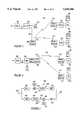
- FIG. 1is a block diagram of an example of a first Video Dial Tone Network utilizing a Level 1 Gateway which may be utilized with the present invention.
- FIG. 2 (2A,2B)is a block diagram of one example of an alternate network architecture utilizing a Level 1 Gateway in a manner adapted to the present invention.
- FIG. 3illustrates a hybrid fiber coax network architecture utilizing the Level 1 Gateway in a manner adapted to the present invention.
- FIG. 4illustrates a digital entertainment terminal which may be utilized with the present invention.
- FIG. 5illustrates the implementation of the invention according to one embodiment utilizing the type of network illustrated in FIG. 1.
- FIG. 6illustrates another embodiment of utilization of the invention in a network of the type illustrated in FIG. 1.
- FIG. 7shows a simplified block diagram of a translator or transponder which may be utilized in the invention.
- FIG. 8illustrates another embodiment of implementation of the invention utilizing the type of network illustrated in FIG. 3.
- FIG. 9illustrates a digital entertainment terminal which may be used with the embodiment of FIG. 8.
- FIG. 10illustrates an on premise implementation of the embodiment of the invention of FIG. 8.
- FIG. 11illustrates yet another embodiment of implementation of the invention utilizing the type of network illustrated in FIG. 3.
- FIG. 12illustrates a set top box or module which may be used with the embodiment of FIG. 11.
- FIG. 13depicts a Network Interface Module (NIM) for interfacing with the Network Entertainment Terminal (NET) as shown in FIG. 11.
- NIMNetwork Interface Module
- FIG. 14depicts details of a Network Entertainment Terminal (NET) which may be used in the embodiment of the invention illustrated in FIG. 11.
- NETNetwork Entertainment Terminal
- FIG. 15illustrates yet another embodiment of the implementation of the invention utilizing the type of network illustrated in FIG. 3.
- FIG. 16depicts a Network Interface Unit (NIU) for interfacing with the network.
- NIUNetwork Interface Unit
- FIG. 17depicts details of the wireless and control signal interface of a network entertainment terminal which may be used in the embodiment of the invention illustrated in FIG. 15.
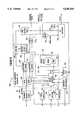
- FIG. 1is a block diagram of an exemplary broadband network for providing interactive services, such as video on demand, home shopping or purchasing, home banking, medical information, ticket ordering, gaming, etc.
- the customer premises equipmentCPE
- CPEcustomer premises equipment
- POTStelephone
- the connections to the central officeutilize Asymmetrical Digital Subscriber Line (ADSL) technology, typically over twisted wire pair, similar to that disclosed in the above cited Litteral et al. Patent.
- the ADSL connectionprovides a 1.5 mbits/s downstream video information channel, a two-way telephone connection and a two-way 16 kbits/s control channel.
- the illustrated Video Dial Tone network architecturemay use some form of fiber extension in the actual subscriber loops, to provide services to subscribers located more than 1.5 kilo-feet from a central office (see e.g. U.S. patent application Ser. No. 08/233,579, in the name of Bruce Kostreski, filed Apr. 26, 1994 and entitled "Extended Range Video On Demand System").
- the drop to the subscriber's premisesis a wired ADSL loop.
- the network interface module in the DET 100connects to an ADSL multiplexer/demultiplexer 201 similar to the in-home ADSL unit in the above discussed Litteral et al. Patent.
- the connection between the network interface module of the DET 100 and the in-home ADSL unit 201may consist of an RJ48C line and connectors.
- Such a linkcomprises six wire pairs, two for the broadband data, two for upstream signaling and two for downstream signaling.
- the distribution on the premisewill differ in the region indicated by the broken line rectangle, as is described in detail hereinafter.
- Each ADSL subscriber line 203connects to an ADSL bay 205 located in or associated with the subscriber's local central office.
- the ADSL bay 205includes an ADSL multiplexer/demultiplexer similar to the central office ADSL unit in the above discussed Litteral et al. Patent.
- the ADSL bay 205provides transport for voice signals on the subscriber loop to and from the associated voice switch 207.
- the ADSL bay 205also connects to an access concentrator 209 for providing two-way signaling connections through an X.25 type packet switched data network 211.
- the ADSL bay 205also receives broadband digital signals for downstream transport over the ADSL line 203 to each subscriber's premises from a digital cross connect switch 213, labelled "Access DCS" in the drawing.
- One ADSL line 203 to the homecarries one channel of video programming and provides a single output channel.
- the output channelcan provide a video signal to a VCR (not shown) or to the TV set 100'.
- the various Access DCS switches throughout the networkare controlled by switch controller 212.
- the ADSL bay 205connects to the Access DCS 213 via an appropriate number of local DS1 connections 215.
- the ADSL baywill be located in a remote central office facility.
- Such a remote ADSL bayconnects to the Access DCS 213 via a SONET type optical fiber link 217 providing an appropriate number of multiplexed channels to service the number of subscribers connected to the particular ADSL bay.
- Video Information service Providersmay access the downstream broadband portion of the system at a hub location (not shown) within a given LATA.
- the hubwill not perform any switching.
- High capacity optical fiber linksare aggregated at the hub to provide each VIP with a number of connections (e.g. one or more OC-3 links) from their respective video server to each Access DCS within the LATA.
- the Access DCS 213provides both point-to-point connections and point-to-multipoint connections.
- Individualized interactive servicessuch as Video On Demand, home shopping/purchasing and banking, use point-to-point connections wherein the Access DCS connects one broadband input port from a VIP's server to one output port going to the subscriber's ADSL line.
- Narrowcast and broadcast servicesutilize point-to-multi-point connections of one input port to a plurality of output ports.
- the illustrated architecture of the Video Dial Tone networkutilizes two levels of gateways, both of which will communicate with subscribers' DET's via the X.25 data network 211 and the signaling channel on the ADSL subscriber loops 203.
- the Level 1 Gateway 221performs a variety of network connectivity related functions, including communications port management of transmissions of information between subscribers and servers, processing of billing information and session management. Normally, each subscriber accesses the Level 1 Gateway (e.g. to select and access a particular VIP's server) by operation of a remote control device which causes the subscriber's DET 100 to transmit data signals to the Level 1 Gateway via the 16 kbits/s control channel and the X.25 packet switched data network 211. The Level 1 Gateway transmits one or more selection menus to the subscriber's DET 100 as screens of text data carried by the same path back through the network.
- the Level 1 Gatewaytransmits one or more selection menus to the subscriber's DET 100 as screens of text data carried by the same path back through the network.
- text or graphics information from the Level 1 Gatewayis displayed as a page of data.
- the text or graphics datacould be overlaid on a video display received through the broadband network, e.g. over one of the broadcast channels carried through the more advanced networks discussed below.
- the userwould turn on the DET terminal 100, and in response to data signals from the Level 1 Gateway 221, the terminal would display an initial selection menu.
- the subscriberwould input a selection, and in response to an appropriate data signal from the DET 100, the Level 1 Gateway 221 would instruct the various network components to set up a virtual circuit to the level 2 gateway of a selected VIP for signaling purposes and a direct downstream path from the VIP's server through the digital cross-connect switch 213 for video transmission.
- the Level 1 Gateway 221accumulates usage statistics relating to the broadband communication links through the network and supplies those statistics to a billing system, e.g. to a carrier access billing system (CABS) 227 as shown in FIG. 1.
- CABScarrier access billing system
- the Level 1 Gateway 221also exchanges various network operational status information with the switch controller 212 and with a video provider service center (VPSC) 231.
- VPSCvideo provider service center
- a level 2 gatewayprovides a number of services for the Information Providers. These services include transmission of menus of available information to subscribers, searches of available information, targeted advertisement insertion, previews, trailers, etc.
- the level 2 gatewaywill download video or audio menus to each subscriber's DET for display, thereby allowing each subscriber to select desired information. Once a subscriber makes a selection, the level 2 gateway will signal the appropriate server to schedule transmission of the selected information through the established downstream video transmission path.
- the Level 1 Gatewayaccumulates connectivity charge information for purposes of billing each called VIP.
- the level 2 gatewayrecords transactions, e.g. movies viewed, by each subscriber for billing purposes.
- the level 2 gatewayalso interacts with the DET 100 and controls the associated servers to download executable program code for storage in the DET system memory.
- the switch controller 212monitors operations of the digital cross connect switches 213 and provides appropriate information to the Level 1 Gateway. For example, if the switch controller 212 indicates that a broadband communication link through one of the switches has failed for some reason, the Level 1 Gateway will terminate its accumulation of usage data for billing for the particular broadband session.
- the video provider service center (VPSC) 231performs a related monitoring function with regard to the ADSL loops.
- the ADSL bays 205monitor communications over the subscriber lines 203 by periodically enquiring as to the status of each on-premise ADSL unit 201.
- the ADSL bays 205in turn inform the video provider service center (VPSC) 231 of any detected failures via data connections to that center (only one such data connection is illustrated in FIG. 1).
- the service center (VPSC) 231is manned with operations support personnel.
- the center 231provides a display for review by one of the technicians.
- a VIPmay also call in and indicate that the VIP's system 252 has detected some form of failure.
- the techniciandecides whether in fact a failure has occurred. If so, the technician initiates an X.25 data call and transmission of a message from the video provider service center (VPSC) 231 to the Level 1 Gateway 221 identifying the failed link and instructing the Gateway 221 to tear down the particular broadband link.
- the Level 1 Gateway 221terminates its accumulation of usage time data for that link and instructs the switch controller 212 to tear down the link.
- personnel at the centercan initiate action to correct the fault. For example, if the switch controller 212 reports a fault in a particular switch 213, the personnel at the service center (VPSC) 231 can call a technician at the central office housing that switch and have that technician test the switch and correct any faults actually discovered. Similarly, if an ADSL bay 205 reports some fault on the twisted wire pair 203 or loss of communications with the on-premises ADSL unit 201, the personnel at the service center (VPSC) 231 can dispatch a repair technician to locate and correct the fault on the line or in the on-premises unit.
- the function of the video provider service center (VPSC) 231be fully automated to instruct the Level 1 Gateway 221 to stop billing data accumulation and tear down faulty broadband links without human intervention.
- the Video Dial Tone network of FIG. 1provides video on demand and other broadband interactive multimedia services offered by a plurality of service providers. For example, using the upstream data channel, the subscriber can send a request for a particular movie from his VIP of choice, and the VIP's server will retrieve and transmit that movie as an MPEG digital data stream on the 1.5 Mbits/s downstream channel to the digital audio/video processor in the subscriber's DET 100.
- MPEGmoving picture experts group
- MPEG 2is a second generation compression standard for packetized transport of one or more compressed video program signals in a single stream.
- a number of specific compression algorithmswill satisfy MPEG requirements.
- MPEGpermits encoding of audio/video program materials into digitized, compressed format at rates in the range of 1.5 to 6 Mbits/sec.
- the DET 100includes a CPU, comprising a 386 or 486 microprocessor and associated memory (RAM, ROM and EPROM) and an audio/video decoder, controlled by the CPU.
- the audio/video decoderdecompresses the digitized broadband information.
- the preferred embodiment of the audio/video decodercomprises an MPEG video decoder, an MPEG audio decoder, and an MPEG demultiplexer for selectively routing MPEG encoded video and audio packets carried on the digital broadband channel to the MPEG video decoder and the MPEG audio decoder, respectively.
- the DETalso includes a graphics display generator for generating displays of received text data, such as the initial turn-on selection menu, discussed in more detail below.
- the DETalso includes digital to analog converters and appropriate drivers to produce output signals compatible with a conventional television set from the decoded audio/video information and the graphics display.
- Each DETalso includes means to receive selection signals from a user and transmit appropriate data signals over a narrowband channel through the particular video network.
- the digital entertainment terminal (DET) 100is a programmable device to which different individual video information providers (VIP's) can download different applications software. At least one VIP, typically a vendor of the DET, also can download portions of the operating system.
- VIPtypically a vendor of the DET
- the DETwill permanently store only an operating system and a loader program, to control initial communications with a Level 1 Gateway or to facilitate initialization into a simplified CATV type mode of operation.
- FIG. 1The operation of the network of FIG. 1 is described in further detail in commonly assigned application Ser. No. 08/304,174 filed Sep. 12, 1994, entitled “Level 1 Gateway for Video Dial Tone Networks” (680-093), which is incorporated entirely herein by reference.
- FIG. 5there is shown one arrangement for providing wireless on-premise distribution of the 1.5 mbits/s downstream video information channel and two-way 16 kbits/s control channel using the ADSL architecture described above in connection with FIG. 1 according to a first embodiment of the invention. It will be understood that the invention is also applicable to other distribution architectures presently to be described. The same reference numerals have been used in FIG. 5 as are found in FIG. 1 where applicable.
- the CPE premiseincludes multiple television sets here indicated at 100' and 100" connected to multiple DET's 100 and 100a. These DETs are in turn connected to ADSL units 201 and 201'.
- the remote ADSL 205is shown beyond the CPE and is connected through a subscriber line to a filter 402 which separates the two-way voiceband signal to the POTS 404 and the multiplexed broadband 1.5 mbits/s television signal and two-way 16 kbits/s signaling channel delivered via connection 406. These signals on connection 406 are inputted to a suitable transponder 408.
- the transponder 408translates the frequency of these inputted signals to the radio frequency range and radiates the same through a suitable antenna 410.
- the radiated signalsare received by antennas 412 and 414 associated with transponders 416 and 418.
- the transponders 416 and 418translate the radio frequency signals back to the original 1.5 mbit/s and 16 kbits/s signals which are then fed as inputs to the ADSL units 201 and 201' for delivery to the DETs 100 and 100a and television sets 100' and 100" in the manner described in connection with FIG. 1.
- the transponderscomprise linear translators having a receiver or input pass band wide enough to include multiple channels. These signals are amplified, shifted to a new frequency range, and in the case of the transponder 408, then transmitted as radio frequency signals without modulation or alteration of the signal content.
- the transponders 416 and 418receive the radio frequency signals, translate the frequency to the original 1.5 mbits/s and 16 kbits/s and input the same to the ADSL units 201 and 201'.
- a typical such transponder or translatoris illustrated in FIG. 7.
- the transponderis in many respects similar to a transceiver in that it possesses a pair of signal handling channels for operating in converse fashions on signals in opposite directions.
- the input/output terminals 424 and 426are served by channel 420 to handle signals in the direction of the arrow 428 while channel 422 handles signals in the opposite direction indicated by the arrow 430.
- Channel 420may receive at input/output terminal 424 the 1.5 mbits/s and 16 kbits/s signals, amplify the same via amplifier 432, and deliver the amplified signals to a mixer 434, fed by the oscillator 436.
- the mixingraises the frequency to the radio frequency range and this signal is passed through a filter 438 and amplifier 440 to the input/output terminal 426.
- the terminal 426would terminate in the antenna 410.
- the transponders 416 and 418 receiving the radio signal from the antenna 410would handle the incoming signals in a converse fashion through the channel 422.
- the radio frequency signalswould be received by an antenna connected to the terminal 426.
- This signalwould pass through amplifier 442, mixer 444, controlled by oscillator 446, filter 448, and amplifier 450.
- the upstream 16 kbits/s control signal from the ADSLis raised to radio frequency and transmitted back to the transponder 408.
- the radio frequency signalis translated back to the 16 kbits/s form and delivered upstream to the remote ADSL 205 for the control purposes described in connection with FIG. 1.
- transponder circuitsmay be utilized in a manner well known in the art. See, Radio Handbook, 23d edition, William Orr, SAMS Division of MacMillan Computer Publishing, 1987; Satellite Communications, Robert M. Gagliardi, Lifetime Learning Publications, 1984; and Digital Satellite Communications, 2d edition, Tri T. Ha, McGraw-Hill Communications Series, McGraw-Hill Publishing Company, 1990.
- FIG. 6there is shown another embodiment of wireless CPE distribution using an ADSL system. Similar reference numbers are used where applicable.
- a single CPE ADSL unitis utilized connected to the subscriber line 203 and feeding the 1.5 mbits/s and 16 kbits/s signals to the transponder 408. These signals are translated to radio frequency and transmitted in turn to transponders 416 and 418. The transponders translate the radio frequency back to the original 1.5 mbits/s and 16 kbits/s signals and deliver the same to the DET's 100 and 100a.
- the return or upstream 16 kbits/s control signalsare translated to radio frequency in transponders 416 and 418, transmitted to transponder 408 and there returned to the 16 kbits/s form for input to the ADSL 201 and transmission upstream to the remote ADSL 205.
- the telephone (POTS or ISDN) circuitis separated from the incoming signal on the subscriber line at the filter 402 (or equivalent) device in the case of an ISDN installation.
- the POTS lineis broken out from the ADSL as described in connection with FIG. 1.
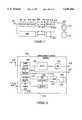
- FIG. 2depicts an example of one such advanced video dial tone network utilizing the Level 1 Gateway.
- the illustrated networkutilizes an advanced fiber to the curb system with ATM (Asynchronous Transport Mode) transport, and is similar to one of the networks disclosed in commonly assigned application Ser. No. 08/250,792, filed May 27, 1994, entitled “Full Service Network” (attorney docket No. 680-080), the disclosure of which is incorporated herein entirely by reference.
- the network of FIG. 2uses essentially a switched star type architecture.
- the Full Service Network illustrated in FIG. 2provides broadcast video distribution, archival video services and interactive multi-media services as well as a suite of narrowband services including plain old telephone service.
- the broadcast video serviceswill initiate from a broadcast type server, such as ATM video source 1101 or aa digitally encoded off the air TV signal.
- the broadcast server source 1101includes an actual analog video source 1110. Although only one is shown, a typical broadcast service provider will have a plurality of such video sources in the same or separate server systems.
- the analog signal from the sourceis carried by any convenient means, such as an optical fiber, etc.
- Means(not shown) are provided as necessary to convert analog video transmission signals, e.g. NTSC broadcast signals, to baseband video and audio signals.
- the baseband signalsare applied to a real time encoder 1120.
- the real time encoder 1120digitizes the audio and video signals and performs data compression. As currently envisaged, the encoder will encode the program signal into an MPEG 2 format.
- the illustrated real time encoder 1120preferably is set up as a bank of encoders to process six or more sets of analog audio/video program signals in parallel.
- the bank of encoders 1110produces six 6 Mbits/sec MPEG 2 bit streams, which are combined together with appropriate overhead information into a single 45 Mbits/sec DS-3 type signal.
- the DS-3 signal from the encoder 1120is input to an interworking unit (IWU) 1130.
- the interworking unit 1130is the actual input point for the encoded broadcast video information into the Full Service Network of FIG. 2.
- the Full Service Networkuses asynchronous transfer mode (ATM) switching to transport all broadband or video information, including the broadcast video information.
- ATMis a packet oriented time division multiplexing technique.
- informationis organized into cells. Each cell includes a header, primarily for identifying cells relating to the same virtual connection, and an information field or "payload".
- a 53 octet ATM cellwould include a cell header consisting of 5 octets and a payload consisting of 48 octets of data.
- One MPEG 2 packetwould be mapped into payload data in four such ATM cells. Transfer is asynchronous in the sense that the recurrence of cells that contain information from any particular sender is not necessarily periodic.
- Each device using the ATM networksubmits a cell for transfer when they have a cell to send, not when they have an assigned or available transmission time slot.
- ATMallows any arbitrary information transfer rate up to the maximum supported by the ATM network, simply by transmitting cells more often as more bandwidth is needed.
- all video materialswill be transferred at a constant, standardized bit rate.
- Preferred later generations of the networkwill utilize the ATM capabilities of the network to permit transmission of video information over channels of different bit rates, e.g. 1.5 Mbits/sec, 3 Mbits/sec, 6 Mbits/sec, etc. It will also be possible to vary the bit rate during communication on an as needed basis.
- the interworking unit 1130grooms the continuous MPEG 2 bit streams of the broadcast services for ATM cell stream transmission over optical fiber transport links. For example, the interworking unit will divide the bit stream into appropriate length payloads and combine the payload data with appropriate cell headers, necessary for ATM transport. In an initial implementation, downstream links would carry an OC-12 bit rate, but higher rate transports such as OC-48 will be used in later implementations. Assuming use of OC-12, one such transport link will normally carry the equivalent of 112 DS-3's. However, conversion into ATM cell format with associated headers imposes added overhead requirements on the data transmissions. In the presently preferred embodiment, one interworking unit 1130 therefore processes up to ten DS-3 signals to produce an ATM bit stream at the OC-12 rate.
- a transport interface 1140converts the electrical signal from the interworking unit 1130 into an optical signal and transmits the optical signal through fiber 1150 to an adaptive digital multiplexer (ADM) identified in the drawing as a video bridging and insertion device 1160.
- ADMadaptive digital multiplexer
- the ADM 1160performs three functions, passive bridging, active bridging and insertion of signals from other broadcast service providers (if any). The three functions may actually be separate, but in the preferred embodiment, all three would be performed by elements collocated within the one network component ADM 1160.
- the real time encoders 1120each output a single DS-3 signal comprising up to 6 MPEG 2 bit streams.
- the interworking unit 1130processes up to ten DS-3 signals to produce an ATM bit stream at the OC-12 rate. Consequently, one broadcast video source 1101 may produce as many as 60 channels of CATV type broadcast programming for transport over one OC-12 type SONET optical fiber 1150. Many providers, however, may not choose to broadcast so many channels. For example, the provider operating broadcast video source 1101 may offer only 42 channels. Such an ATM channel transmission on the optical fiber 1150 will not utilize the entire OC-12 channel capacity of that fiber. In the specific example, the 42 channels together require the equivalent of 7 of the available 10 DS-3's.
- the illustrated architecturepermits a second broadcast service provider to utilize the transport capacity not used by the first provider.
- the second broadcast service providerwould offer additional channels from a separate second source 1101'.
- the source 1101'is essentially identical in structure and operation to the source 1101, but the source 1101' will offer up to the number of channels necessary to fill the OC-12 transport capacity. In the example, if the source 1101 transmits 42 channels (7 DS-3's) via the fiber 1150, the second source 1101' could transmit up to 18 additional channels (3 DS-3's).
- the function of the insertion device in the ADM 1160is to combine the signals from the two sources into a single OC-12 rate signal (10 DS-3's in ATM cell format) for further transmission through the optical network.
- the two bridging functionsfacilitate dissemination of the broadcast material throughout the entire Full Service Network.
- the passive bridging elementsare optical splitters for splitting one OC-12 optical signal from the insertion device into a number of duplicates thereof, e.g. 1:2, 1:4, 1:8, etc.
- the active bridging elementsconvert an optical signal to an electrical signal, regenerate the electrical signal and convert the regenerated signal back to an optical signal for application to multiple output ports.
- the optical OC-12 output signals from the bridging componentsare transmitted over a large number of optical fibers 1170 to host digital terminals throughout the network service area.
- the host data terminal (HDT) 1180is shown as a representative example.
- the digital entertainment terminal (DET) in the subscriber's homeprovides a signal identifying the selected channel to the HDT 1180.
- the signaling between the digital entertainment terminal (DET) and the HDT 1180will be discussed in more detail below.
- the ATM cell stream from an optical fiber 1170is applied to a bus.
- One HDTwill communicate with a large number of optical network unit (ONU's) 1210, two of which are shown.
- the HDTwill communicate with each ONU 1210 via a pair of optical fibers 1190.
- each home or living unitwill have as many as four DET's.
- Each ONU 1210 and the downstream fiber of the pair 1190 to the ONU 1210will provide downstream video services to a number of homes, e.g. 8 to 24.
- the transmissions on the downstream fibers between the HDT and the ONU's 1210are synchronous, although the video information remains in ATM cell format.
- Each DET served by an ONU 1210is assigned a specified time slot on the downstream fiber of a pair 1190.
- the HDT 1180includes a component which is essentially a non-blocking type ATM switch.
- the HDT 1180accesses the appropriate bus and identifies each ATM cell on that bus for which the header information indicates that the cell represents information for the selected broadcast channel.
- the identified ATM cellsare bridged by the ATM switch from the bus to a line card providing transmissions over the optical fiber 1190 to the particular ONU 1210 which services the requesting subscriber's premises.
- elements on the line card communicating with the particular ONUwill buffer the cell as necessary and place the cell in the time slot for that DET on the downstream fiber of optical fiber pair 1190.
- the cells selected for a particular DETtogether with cells going to other DET's served by the same ONU multiplexed into their respective time slots, are applied to an electrical to optical converter and transmitted over the downstream fiber to the ONU 1210 serving the particular subscriber's premises.
- the basic purpose of the ONUis to desegregate the HDT side links into individual customer links and provide optical to electrical conversion for electrical delivery to the individual subscribers' premises.
- the drop cable to each subscriber's premisescomprises a coaxial cable for carrying the video and/or two-way digital data signals and a twisted wire pair for carrying telephone signaling.
- ADSL communications over twisted wire paircould be used between the ONU and the subscribers premises.
- the ONUincludes means to convert optical signals received over the downstream fiber to electrical signals and transmit signals from each DET's assigned time slot down over the coaxial cable to the subscriber's premises.
- the ONUalso provides two-way conversion between optical and electrical signals for voice telephone service over the twisted wire pairs and for the signaling channels to/from the DET's.
- a power source 1211supplies -130 V dc and battery reserve power for telephone service to the ONU's 1210.
- the power source 1211may connect to the ONU's via twisted pairs, but in the preferred embodiment, the power is carried over a coax distribution cable.
- the digital entertainment terminal (DET) 1217is a programmable device to which different applications programs and/or portions of the operating system will be downloaded from a gateway device in order to permit the DET to interact with different information service providers and thereby offer the user totally different types of services.
- the DETmay be similar to that used in the network of FIG. 1, with the exception that the network interface module within the DET 1217 provides the various broadband and signaling connections to a coaxial cable, instead of to an interface to an ADSL twisted wire pair type line, and the communication software within the DET is adapted to process ATM transported information.
- the DET 1217includes means (not shown) to demodulate received data and convert ATM cell stream data into bit stream data for further processing.
- the DET 1217also includes a digital signal processor to decompress received video signals as well as a graphics display generator for generating displays of text data, such as the initial turn-on selection menu.
- the DETwill also include a digital to analog converter and appropriate drivers to produce output signals compatible with a conventional television set.
- Each DET 1217also includes the means to receive selection signals from a user and transmit appropriate data signals over a narrowband channel on the coaxial drop cable to the ONU 1210.
- the ONUmultiplexes the user input data signals from the DET's it services together and transmits those signals to the HDT over an upstream fiber of the optical fiber pair 1190.
- the HDTtransmits the upstream control signals to control elements referred to as gateways.
- the HDT'scommunicate with the gateways through an X.25 type data network. Future implementations will use ATM communications for the signaling.
- the Level 1 Gateway 1230provides primary control of all routing and access functions of the network and accumulates various usage statistics, in a manner substantially similar to that of the Level 1 Gateway 221 in the network of FIG. 1.
- the control functionsinclude controlling access to broadcast programs by individual subscribers. Control of access to on demand programming and interactive multimedia services through a PVC controller 1420 and an ATM switch 1410 will be discussed in more detail below.
- the Level 1 Gatewayalso will transmit narrowband information to the DET 1217 instructing it to initiate display of various selection menus of available video information service providers.
- the Level 1 Gatewayconnects to a service administration module (SAM) which maintains a data base of video information service providers and customer profile data for the broadcast, archival and interactive video services available through the network. This data may include customized menus, pre-subscription information, identification of impulse pay per view events and premium channels, etc. Under different circumstances, the video information providers and/or the individual customers can access this data for provisioning.
- SAMservice administration module
- the Level 1 Gatewayalso connects to an operations support module (OSM).
- OSMoperations support module
- the operations support moduleprovides an interface to standard operating support systems used for additional network provisioning functions.
- the DET 1217transmits data upstream through the various network elements to the Level 1 Gateway identifying the selected channel.
- the Level 1 Gateway 1230accesses stored data regarding the broadcast services to which the customer currently subscribes. If the customer subscribes to the requested service, the Level 1 Gateway 1230 transmits an instruction to the HDT 1180 to route the cells for that channel to the subscriber's DET 1217 in the manner discussed above. If the customer is not currently a subscriber to that service, the Level 1 Gateway 1230 transmits a data message back to the DET 1217 instructing it to provide an appropriate television display, e.g. informing the customer of a service denial and/or asking the subscriber for appropriate inputs to initiate a new subscription.
- the above selection procedure through the Level 1 Gatewayprovides the Gateway 1230 with information as to each selection a subscriber makes and when the selection is made.
- the Level 1 Gatewayalso receives information as to when a DET session ends, e.g. upon turn-off of the DET or upon request for a session with a different provider.
- the Level 1 Gatewayhas all information necessary to accumulate a variety of statistics as to viewer usage both for billing purposes and for audience accounting purposes.
- certain relevant control datacould be downloaded to the HDT, either from the Gateway 1230 or from the service administration module (SAM).
- SAMservice administration module
- the broadcast VIP'swould provide provisioning data to the SAM, and the SAM periodically downloads that data to the appropriate HDT's, either directly or through the Level 1 Gateway 1230.
- the provisioning data downloaded to the HDT's 1180would include channel mapping information and subscriber authorization control information.
- the channel mapping informationspecifies what programs are carried on each ATM virtual circuit, within each DS-3, on each respective optical fiber 1170.
- the HDT 1180accesses the channel mapping information in response to each program selection by a subscriber to route the ATM cell stream to the requesting DET.
- the authorization control datawould indicate which program each subscriber is authorized to access, e.g. because that party has subscribed to the particular program service and is not delinquent in bill payments. When a subscriber requests a program, the HDT 1180 would check this data to determine whether or not to supply the program to the subscriber's DET 1217.
- the HDT 1180As the HDT 1180 routes selected channels to the DET's 1217, the HDT would accumulate usage data and/or pay per view event purchase data for the subscribers serviced thereby. The HDT 1180 would periodically upload such usage data to the Level 1 Gateway 1230 and/or to the SAM for subsequent transmission to appropriate billing systems of the network service provider or the VIP's, respectively.
- the network of FIG. 2offers subscribers access to other wideband services, such as video on demand and interactive multimedia services. Access to these additional broadband services is through an ATM switch 1410. As discussed in more detail below, the access through this switch is controlled by the Level 1 Gateway 1230 in a manner quite similar to the routing to a VIP in the network of FIG. 1.
- Each of the non-broadcast service providers 1400will have a level 2 Gateway 1401 and some form of file server 1403 or other source of information.
- the video information provider's (VIP's) systemmay provide ATM cell stream outputs for transmission through the network.
- the network operatorwould supply an interworking unit similar to the unit 1130 discussed above to convert the provider's bit stream data into an ATM cell stream format compatible with the Full Service Network.
- the ATM switchtransmits selected ATM cells via optical fibers 1415 to the HDT's 1180.
- a PVC controller 1420stores data tables defining all possible virtual circuits through the ATM switch and the HDT's to each terminal of a customer subscribing to a particular provider's services. These data tables define the header information and the particular fiber output port used to route cells to the correct HDT and the time slot information on the downstream fiber to the appropriate ONU serving each DET. The data tables thus define "permanent virtual circuits" (PVC's) between the providers and the DET's.
- the subscriber's DET 1217When a subscriber initiates a session with a broadband interactive service provider, for example VIP 1400, the subscriber's DET 1217 provides an appropriate "off-hook" signal to the HDT 1180.
- the HDT 1180sends the message through the X.25 packet switched network to the Level 1 Gateway 1230.
- signalingmay also be achieved using ATM calls through HDT and ATM video switch to the level 1 Gateway 1230.
- the Level 1 Gateway 1230receives the addressed message from the HDT, that Gateway uses the X.121 or other protocols address of the caller included in the message to check its internal database to determine if the caller is a valid network customer. If the caller is not a valid customer, the system tears downs the session. If the caller is a valid customer, the Level 1 Gateway 1230 transmits an X.25 or ATM call accept message back to the terminal and waits for the first application level message.
- the DET 1217sends an initiation message that says "hello".
- This "hello" messageincludes basic information such as a customer premises equipment (CPE) identifier and a CPE type designation.
- the Level 1 Gateway 1230sends a menu and a banner through the downstream signaling channel, as in the earlier network embodiment.
- the menuis a screen of text listing VIP's available to this customer or the VIP's that the customer as previously selected for purposes of her customized menu presentation.
- the subscriberreviews the menu on their television set, and operates the arrow keys on the DET remote control to move a cursor across the menu to an appropriate point on the screen, after which the user presses an ⁇ ENTER> key on the keypad or remote control.
- the DET 1217transmits an appropriate data signal upstream through the network to the Level 1 Gateway 1230.
- the Level 1 Gatewaymay execute a PIN number access routine, as in the earlier embodiment, if the subscriber has previously requested such access control for selected ones of the VIP's. For simplicity here, it is assumed that the currently selected VIP is not subject to such a PIN number requirement.
- the Level 1 Gatewayis merely expecting to receive the VIP selection input from the DET within a predetermined period following the menu transmission. If the Level 1 Gateway receives the selection input message from the DET within the predetermined period, the Gateway 1230 translates that message into the 4 digit code for the selected VIP's Level 2 Gateway.
- the Level 1 Gatewaysends a message to the DET saying please wait while we connect to the VIP.
- the Level 1 Gatewaythen goes over the X.25 or ATM network to communicate with the selected VIP's Level 2 Gateway.
- the Level 1 Gateway 1230contacts the level 2 Gateway 1401 and indicates that it has a customer calling.
- the Level 1 Gateway 1230identifies the customer to the level 2 Gateway 1401 by sending the standard billing telephone number for the calling customer to the Level 2 Gateway.
- the CPE identification information and the CPE-type information that was sent in the initial origination messageis also sent to the Level 2 Gateway (VIP) at this time.
- VIPLevel 2 Gateway
- the VIP's Level 2 Gatewaymay accept or reject the call after receiving the initial request indicating a customer is available, as in the network of FIG. 1. If the Level 2 Gateway 1402 sends a message back to the Level 1 Gateway 1230 indicating a rejection of the call, the Level 1 Gateway transmits a message to the DET 1217 instructing that terminal to display some form of call rejection notice on the associated TV.
- the Level 2 Gateway 1401accepts the call, provides a server output port and gives a port identification for the port on the server 1403 to the Level 1 Gateway 1230.
- the Level 1 Gatewaytransmits the X.121 address of the calling customer's DET 1217 to the Level 2 Gateway 1401.
- the Level 2 Gatewayuses that address to initiate a new signaling communication through the X.25 network 1220 with the subscriber's set-top terminal DET 1217.
- the Level 1 Gatewayidentifies the broadband communication link number for the channel going out from the HDT to the requesting customer's DET 1217.
- the Gateway 1230sends a message to the PVC controller 1420 to establish a virtual circuit between the selected provider 1400 and the subscriber's DET 1217.
- the PVC controlleraccesses its data tables to identify an available permanent virtual circuit between the provider 1400 and the DET 1217 for which all necessary elements are currently available.
- the PVC controller 1420provides appropriate instructions to the ATM switch 1410 and informs the Level 1 Gateway 1230 of the virtual circuit identifier.
- the Level 1 Gateway 1230informs the HDT 1180 of that virtual circuit identifier and instructs the HDT 1180 to "lock-up" that circuit as a currently active virtual circuit providing broadband communications from the server 1403 of the provider 1400 to the subscriber's DET 1217.
- the PVC controller 1420transmits back an appropriate indication thereof to the Level 1 Gateway 1230. Then the Level 1 Gateway tears down its own X.25 signaling connection with the subscriber's set-top terminal. At the same time, the Level 1 Gateway 1230 informs the Level 2 Gateway 1401 that it has set up a good broadband link, and the Level 1 Gateway initiates a billing record for the call. Alternatively, if the PVC controller 1420 informs the Level 1 Gateway 1230 that it could not establish the broadband connection, the Level 1 Gateway passes that information on to the Level 2 Gateway 1401 and provides an appropriate message for display by the DET 1217 informing the customer.
- the DETcan transmit control signaling upstream through the ONU 1210 the HDT 1180 and the X.25 data network to the Level 2 Gateway 1401.
- the Level 2 Gatewaycan also send signaling information, such as control data and text/graphics, downstream through the same path to the DET 1217.
- the server 1403will provide ATM cells with an appropriate header.
- the ATM switch 1410will route the cells using the header and transmit those cells over fiber 1415 to the HDT serving the requesting subscriber.
- the HDT 1180will recognize the header as currently assigned to the particular DET 1217 and will forward those cells through the downstream fiber of pair 1190 and the ONU 1210 to that DET, in essentially the same manner as for broadcast programming.
- the Level 2 Gatewayinstructs the Level 1 Gateway 1230 to tear down the broadband connection.
- the instructionincludes the customer's billing telephone number and the server port identification for the VIP port used for the broadband communication.
- the Level 1 Gateway 1230stops the billing timing for that broadband session and transmits and instruction through the PVC controller 1420 to tear down the broadband connection between the server port and the customer's broadband port.
- the Level 1 Gatewaycreates a log record of the interactive broadband call for purposes of billing the VIP 1400 for the broadband connect time.
- the Full Service Network illustrated in FIG. 2will also provide narrowband transport for voice and narrowband data services.
- a digital switch 1310 or an analog switch 1330will provide standard type plain old telephone service (POTS) for customers of the Full Service Network.
- POTSplain old telephone service
- the digital POTS switchprovides a DS-1 type digital input/output port through interfaces conforming to either TR008 or TR303.
- the outputmay go to a digital cross-connect switch (DCS) 1320 for routing to the various HDT's or directly to a multiplexer (MUX) 1325 serving a particular HDT.
- the MUX 1325may also receive telephone signals in DS-1 format from the analog switch through a central office terminal 1333.
- the central office terminal 1333converts analog signals to digital and digital signals to analog as necessary to allow communication between the analog switch 1330 and the rest of the network.
- the MUX 1325serves to multiplex a number of DS-1 signals for transmission over one fiber of an optical fiber pair 1335 to the HDT 1180 and to demultiplex signals received over the other fiber of the pair 1335.
- the fiber pairs between the HDT 1180 and the ONU's 1210will also have a number of DS-1 channels to carry telephone and narrowband data signals to and from the subscriber's premises.
- the subscribers' drops 1215include both a coaxial cable and one or more twisted wire pairs.
- the ONUwill provide telephone signals and appropriate power to the subscribers' premises over the twisted wire pairs connected to subscribers' telephone sets 1219.
- the ONU'swill also provide two-way narrowband data communication to the DET's in narrowband channels over coaxial cable.
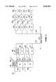
- FIG. 3depicts an alternate implementation of a further video network utilizing a Level 1 Gateway in accordance with the present invention.
- the network of FIG. 3is a hybrid fiber-coax system which provides RF transport of both analog and digital broadband services.
- the illustrated networkprovides broadcast video distribution, archival video services and interactive multi-media services as well as plain old telephone service.
- a telcodeploys a number of Loop Transport Interfaces 300, only one of which appears in the drawing (FIG. 3).
- each Loop Transport Interface 300will be located in a telco central office.
- several different central officeswould each have a Loop Transport Interface similar in structure to the Interface 300 depicted in FIG. 3.
- each Loop Transport Interfacewill serve as the headend of an otherwise conventional optical fiber trunk and coaxial cable type CATV distribution network.
- a laser type optical transmitter 303transmits downstream signals through fibers 305 to optical to electrical nodes referred to as "optical network units" or ONU's.
- the laseroperates in a linear mode in the range of 5-750 MHz.
- the transmitterhas an optical splitter and can transmit to several ONU nodes 309. Each ONU 309 performs optical to electrical conversion on the downstream signals and supplies downstream RF electrical signals to a coaxial cable distribution system 311.
- the optical transmitterreceives and transmits signals from an RF (radio frequency) combiner 315.
- the combiner 315combines and levelizes RF signals from several sources to produce the appropriate signal spectrum for driving the optical transmitter 303.
- One set of signals supplied to the RF combiner 315will be group of AM--VSB (amplitude modulated vestigial sideband) analog television signals from one or more appropriate sources not separately shown.
- AM--VSBamplitude modulated vestigial sideband
- Such signalsare essentially "in-the-clear" CATV type broadcast signals capable of reception by any subscriber's cable ready television set.
- the analog television signalsare broadcast from the optical transmitter 303 through the tree and branch optical and coax distribution network to provide "basic" CATV type service to all subscribers on the network.
- the Network operating companyoffers a standard CATV type analog frequency converter, or the subscriber could choose to purchase a converter on the open market.
- the network interface module in the DET 100awill also include a tuner that permits subscribers to the digital services to receive the analog broadcast channels through the same equipment used for the digital services.
- the Network depicted in FIG. 3also provides transport for digitized and compressed audio/video programming, both for certain broadcast services and for interactive services, such as video on demand. Such programming will be encoded and compressed in MPEG-2 or other format. As discussed in more detail below, the present invention permits specific use of MPEG encoded materials to offer a variety of interactive services without continuously utilizing a full MPEG encoded broadband channel to transport information to the subscriber's DET 100'.
- the MPEG encoded videois transported to each Loop Transport Interface using asynchronous transfer mode (ATM) transport and switching.
- ATM informationis organized into cells each comprising a header, primarily for identifying cells relating to the same virtual connection, and an information field or "payload".
- the ATM cell header informationincludes a virtual circuit identifier/virtual path identifier (VCI/VPI) to identify the particular communication each cell relates to.
- VCI/VPIvirtual circuit identifier/virtual path identifier
- the VCI/VPIwill identify a particular program channel.
- the VCI/VPI in each header of the ATM cellswould effectively identify a specific end point of the virtual communication link.
- digital broadcast service signals 318 in MPEG encoded form and arranged in ATM cell packetsare applied to an ATM packet handler 319 in the Loop Transport Interface 300.
- These broadcast service signalsoriginate in one or more broadcast VIP's ATM servers which are essentially the same structure as the servers/sources 1101, 1101 shown in FIG. 2.
- the ATM broadcast serviceswill carry premium service type programming.
- the ATM broadcast signalsmay originate from any appropriate source (not shown).
- the ATM broadcast cell stream signalsoriginate from a server 403', as discussed in more detail below.
- Fully interactive broadband digital signals, in MPEG--ATM formatare also applied to the ATM packet handler from an ATM switch 401.
- the ATM packet handler 319terminates all ATM cell transport through the Network. This handler receives the ATM cell streams and converts the cell payload information into MPEG 2 bit streams.
- the RF combiner 315which prepares signals for downstream transmission by the optical transmitter 303 receives a variety of other analog RF signals from a group of RF digital modulators.
- the RF analog outputs from the modulatorscarry digital broadband information.
- the content for the digital RF modulatorscomes from the ATM packet handler 319.
- a network controller 323 and an associated network data processor (NDP) 325use the VCI/VPI header from the ATM cells to control the ATM packet handler 319 to route the MPEG bit streams to the appropriate ones of the digital RF modulators 317.
- U.S. Pat. No. 5,231,494 to Wachobteaches quadrature phase shift keyed (QPSK) modulation of a plurality of video, audio and data signals into a single data stream within a standard six MHz channel allocation for transmission over a CATV type distribution network.
- QPSKquadrature phase shift keyed
- the currently preferred implementationuses 64 QAM (quadrature amplitude modulation) or 16 VSB (vestigial sideband) modulation techniques in the RF modulators 317 in the Loop Transport Interface 300.
- 64 QAMquadrature amplitude modulation
- 16 VSBvestigial sideband modulation techniques
- 4 channels of 6 Mbits/s MPEG encoded digital video informationcan be modulated into one 6 MHz bandwidth analog channel.
- 16 VSByields 6 channels of 6 Mbits/s MPEG encoded digital video information modulated into one 6 MHz bandwidth analog channel.
- Each RF modulatorproduces a 6 MHz bandwidth output at a different carrier frequency.
- the 6 MHz bandwidth RF signals from the modulators 317are supplied to the optical transmitter 303 for downstream transmission together in a combined spectrum with the AM--VSB analog television signals 316.
- the downstream transport of the digital programmingis an RF transmission exactly the same as for the analog basic service channels, but each of the channels from the RF modulators 317 contains 4 or 6 digitized and compressed video program channels, referred to hereinafter as "slots".
- the 6 Mhz digital program channelswill be carried through the fiber and coaxial system in standard CATV channels not used by the analog basic service programming.
- the ONU 309is essentially transparent to both the analog basic service channels and the channels carrying the digital programming and supplies all of the signals as a combined broadcast over the coaxial cable network 311.
- the optical fiber 305 from the transmitter, the ONU's 309 and the coaxial distribution systems 311 thereforprovide a broadcast network transporting all downstream programming to all subscriber premises serviced thereby.
- a network interface modulecouples the set-top device or digital entertainment terminal (DET) 100a to a drop cable of the coaxial distribution network 311.
- the NIMincludes an analog frequency tuner controlled by a microprocessor to selectively receive the RF channel signals, including those channels carrying digital information.
- the NIMalso includes a QPSK, QAM or VSB demodulator to demodulate a selected one of the digitized program signals carried in one of the digital slots within a received 6 MHz channel and will perform a forward error correction function on the demodulated data.
- the digital audio/video signal processor 2125 within the DETdecompresses received video signals, generates graphics display information and performs digital to analog conversion to produce output signals compatible with a conventional television set 100', exactly as in the earlier embodiments.
- the analog tuner in the NIMwill tune in all channel frequencies carried by the network, including those used for the analog broadcast services.
- the DET 100aincludes a bypass switch or the like and an analog demodulator to selectively supply analog signals from the basic service channels directly to the audio/video output terminals or to the modulator, to provide signals to drive a standard television receiver.
- the DET 100atherefore can be used as a frequency converter for reception of the analog signals.
- each DET 100aincludes a remote control and/or keypad to receive various selection signals from a user. At least in response to certain user inputs, such as selection of a pay per view event, the DET will relay data signals upstream over a signaling channel on the coaxial cable to the ONU 309. The actual transmission of any such data signals upstream from the DET 100a occurs in response to a polling of the DET by the ONU 309. The ONU 309 combines upstream data signals from the DET's serviced thereby and transmits those signals upstream over another optical fiber 307 to an optical receiver 308 in the Loop Transport Interface 300. Each DET 100a may transmit data on a different carrier frequency, in which case the network controller knows which DET sent particular data based on the received frequency channel. Alternatively, for interactive services, the DET may transmit a unique identification code with the upstream message.
- Certain digital program signals carried on the networkmay be encrypted using encryption technology and key codes. Details of specific encryption algorithms, the key codes and the precise techniques for downloading the key codes to the DET's are well known to those skilled in the art and familiar with the relevant patents and literature.
- an ACC 4000D 331serves as a video administration module (VAM). Obviously other equivalent products may be substituted.
- the ACC 4000D or VAMperforms set top management and specific program access control functions.
- service profiles for each customer on the network and their DET'sare set up and stored within the Level 1 Gateway 411.
- the Level 1 Gateway 411may also provide an interface to appropriate billing systems (not shown) for some broadcast services, such as pay per view.
- a subscriberwhen a subscriber first signs up, a portfolio of channels subscribed to by that customer is established in the subscriber's profile data within the VAM 331. Based on this profile data, the VAM will download a service map into the subscriber's DET 100a.
- the downstream transmission portion of the networkprovides an out-of-band downstream signaling channel to the DET's, for example for the downloading of the service map information from the VAM 331 to each DET 100a.
- This downstream signaling channelalso carries signals for controlling software downloading and/or selection of certain channels or frames for decoding in interactive services.
- each DET 100aincludes means for receiving and decoding each such digital broadcast service channel, as discussed above with regard to FIG. 1.
- the microprocessor in the DET 100acontrols access to any of these channels based on the downloaded map information stored in the system memory. For example, if one subscriber requests HBO, and that subscriber has paid to subscribe to HBO, the subscriber's DET 100a will contain map information instructing it to tune the RF channel and select and decode the digital program slot carrying HBO for display on the subscriber's television set 100'. However, if a requesting subscriber has not paid for HBO, the downloaded service map will not provide the requisite data for tuning and decoding of that channel.
- the illustrated Networkalso offers pay per view services through the ATM broadcast program channels 318.
- a userselects a pay per view event by operating the DET 100a.
- the DET 100atransmits a purchase message upstream through the Loop Transport Interface 300 to the Level 1 Gateway 411. If the authorization data in the subscriber's profile in the Level 1 Gateway indicates that the DET identification is valid and the subscriber is authorized to purchase such events, the Level 1 Gateway instructs the video manager 417 to authorize reception (and provide a decryption key if needed).
- the DET 100adecodes the pay per view event in essentially the same manner as for other premium services carried on the ATM broadcast channels 318, as outlined above. If the decryption key is needed, the Level 1 Gateway 411 actually instructs the video manager 417 to instruct the VAM 331 to transmit the key to subscriber's DET 100a.
- the implementation of the network illustrated in FIG. 3also provides telephone service. Between the optical network unit and the subscriber premises, the 700-750 MHz portion of the spectrum on the coaxial cable will carry the telephone signals. This allocated spectrum provides transport for 24 DS0 telephone channels. Each subscriber premises will have telephone interface referred to as a Cable Network Unit (CNU) 340 coupled to the coaxial cable which serves to couple two-way signals between a twisted wire pair into the home and the telephone frequency channels on the coaxial cable 311.
- CNUCable Network Unit
- Carrier frequencies used for telephone servicesmay be individually assigned to particular subscriber's CNU's. Also, the telephone signal spectrum is carried on the same two fibers that carry the video and the upstream signaling between the Loop Transport Interface and the ONU.
- Upstream telephone signalsare applied from the optical receiver 308 to a host digital terminal (HDT) 343 which provides an interface to a standard digital telephone switch 345. Downstream telephone signals from that switch pass through the HDT 343 to the RF combiner 315 for transmission in the 700-750 MHz frequency range over the fiber to the ONU 309 and the coaxial cable distribution system 311.
- HDThost digital terminal
- the Loop Transport Interface 300would dynamically allocate the DS0 channels on the coaxial cable system 311 on a time-sharing basis, in essentially the same manner as in mobile radio systems. Two additional fibers and a second optical transmitter and receiver pair would carry the two-way telephone signals to and from the ONU 309. Because of the use of the separate optical links for telephone service in this alternate implementation the HDT and telephone switch need not be closely associated or collocated with any particular one of the Loop Transport Interfaces.
- each VIPhas a Level 2 Gateway and some form of broadband information file server 403.
- the ATM switch 401provides communications links between the Loop Transport Interfaces 300 and the Level 2 Gateways and file servers 403.
- Customer access to the VIP'sis controlled through one or possibly more programmed computer or processor elements performing the processing functions of the Level 1 Gateway 411.
- a permanent virtual circuit (PVC) controller 415 and a video manager 417respond to signals from the Level 1 Gateway to control the point to point routing through the Network.
- PVCpermanent virtual circuit
- the PVC controller 415stores data tables defining all possible virtual circuits through the ATM switch 401 and the Loop Transport Interface 300 serving each DET terminal of a customer subscribing to each particular provider's services. These data tables define the header information and the switch port to the packet handlers needed to route cells to the correct Loop Transport Interface.
- the video manager 417stores similar data tables identifying the transmission fiber ports, RF channels and multiplexed digital channel slots which may be used to transport each data stream processed by the ATM packet handler 319 through the fiber 305 to the appropriate ONU 309 serving each DET.
- the data tables in the PVC controller 415 and the video manager 417thus define "permanent virtual circuits" between the VIP's equipment 403 and the DET's 100a.
- the subscriberoperates the DET 100a to interact with the Level 1 Gateway 411 and select a VIP in a manner similar to the operation in the network of FIG. 1.
- the PVC controller 415responds to instructions from the Level 1 Gateway by activating the ATM switch 401 to establish a downstream virtual circuit path between a port of the VIP's server and the ATM packet handler within the Loop Transport Interface 300 servicing a subscriber requesting a call connection to the particular VIP.
- the video manager 411assigns a particular one of the digitized video channel slots in a digital program type RF channel to carry the particular point to point communication.
- the video managercontrols the ATM packet handler 319 to route MPEG data recovered from the ATM cells for the particular point to point communication to the port for one of the RF modulators 317 so that the modulator will include the MPEG data in the assigned digital channel slot within a particular 6 MHz RF channel.
- the video manager 417also transmits a signal downstream through the signaling channel to the subscriber's DET 100a instructing the DET to tune to the particular RF channel and decode MPEG data from the specifically assigned digital channel within that RF channel.
- Similar dynamic assignments of RF channels on a CATV system to individual terminals for interactive servicesare disclosed in U.S. Pat. No. 5,220,420 to Hoarty et al. and U.S. Pat. No. 5,136,411 to Paik et al., the disclosures of which are incorporated herein in the entirety by reference.
- Level 1 Gateway 411would instruct the PVC controller 415 to control the ATM switch 401 to establish an upstream virtual circuit for control signals sent from the DET 100a up through the fiber-coax network and receiver 308 to the VIP's level 2, gateway.
- the combination of upstream and downstream, point to point channelsare used for downloading of operating system and applications software and for interactive service communications in essentially the same manner as in the Video Dial Tone Network of FIG. 1.
- the Level 1 Gateway 411receives status and failure notifications as part of its ongoing operations. These functions of the Gateway 411 are quite similar to those of the Gateway 212 in the network of FIG. 1 except that the Gateway 411 receives event notifications from more elements of the network. Also, in the presently preferred embodiment of the network of FIG. 3, the function of monitoring communications between the loop transport interface 300 and individual subscribers' DET's 100a is an automatic function of the video manager 417. In such an embodiment, there is no longer a need for the video provider service center (VPSC).
- VPSCvideo provider service center
- the video manager 417could periodically transmit a status interrogation signal to each DET 100a, through the out-of-band signaling channel. If currently operable, the DET would transmit a status message back upstream through the signaling channel informing the manager 417 of the DET's status, e.g. operable but idle or operable and actively in-service.
- a DET 100a detecting some problemcould transmit a fault signal upstream through the signaling channel to the video manager 417, either immediately in response to fault detection or in response the next periodic interrogation by the video manager.
- the video manager 417would also interpret a failure of a DET 100a to respond to an interrogation or to confirm any other message sent to the DET within a predefined period of time as a fault condition.
- the Level 1 Gateway 411may receive an indication from the PVC controller 415 and/or the video manager 417 that one or both can not establish a desired broadband connection.
- the PVC controller 415also monitors ongoing operations of the ATM switch 401, and the video manager 417 monitors communications through the loop transport interface 300 at all times, and each will inform the Level 1 Gateway 411 upon detection of any fault or interruption in any currently established broadband connection.
- the Level 1 Gateway 411transmits notice of an inability to establish a desired broadband session through the signaling channel to the requesting DET 100a, using notices such as shown in FIGS. 2F and 2G depending on whether or not other VIP's are available to the particular subscriber at the time of the call.
- Level 1 Gateway 411receives notice of a fault in an already established session, the Gateway 411 stops accumulating billing data for that session and transmits a message regarding the failure to the VIP's Level 2 Gateway.
- the Level 2 Gatewaymay provide an appropriate notice to the subscriber through the signaling link, if that portion of the session is still operative. Alternatively, the Level 1 Gateway may transmit an appropriate display notice to the DET 100a through the signaling channel.
- Level 1 Gateway 411instructs the PVC controller 415 and the video manager 417 to tear down a broadband communication session
- the Gateway 411expects responses from both of those controllers 415, 417 within a predetermined time interval. If either the PVC controller 415 or the video manager 417 does not respond within the predetermined time interval, the Level 1 Gateway 411 will send an ABORT message to the non-responsive controller 415 or 417 to cancel the original session establishment message, and the Gateway 411 will also record the failure in an alarm file.
- the DETwill connect to a number of different types of networks, such as the Video Dial Tone Network shown in FIG. 1, and more advanced video distribution networks disclosed in commonly assigned application Ser. No. 08/250,792 filed May 27, 1994, entitled “Full Service Network” (680-080), the disclosure of which is incorporated herein entirely by reference.
- the DET 2100will include a network interface module 2101 providing the actual physical connection to the particular type of network.
- the network interface module 2101will also perform any format conversion necessary between signal formats utilized by the network and signal formats used within the DET 2100.
- the module 2101presents two connections to the rest of the DET, a high bit rate broadband connection and a low bit rate signaling connection.
- the broadband connectionis a one-way downstream only connection, but the low bit rate signaling connection is a two-way connection.
- the network interface modulewould provide corresponding connections to an in home ADSL multiplexer unit.
- the ADSL unitcould be included as one or more additional chips within the DET.
- the network interface modulewould include means to multiplex and demultiplex signals for transmission/reception over the coaxial cable or optical fiber.
- the network interface modulewould also include the means to physically connect to the particular network.
- the modulewould include a means for two-way conversion between electrical and optical signals and connections to one or more optical fibers for the necessary two-way transmission.
- the network interface module 2101takes the form of a plug in module.
- the module 2101would be similar to a daughter board or option card which can be plugged into a back plane of a personal computer (PC).
- PCpersonal computer
- typically a techniciancould replace the module in either the field or the shop, to modify a DET to connect to and communicate over a different network, and the technician would modify associated communications control software in the system memory.
- Alternative implementationsmay use a user replaceable cartridge type network interface module, similar to a video game cartridge, which may include memory in the module for storage of the communications control.
- the network interface modulecould include a digital signal processor controlled by the CPU of the DET and input/output connections compatible with all of the digital broadband networks currently available. The downloaded operating system software stored in the system memory of the DET would control operations of the digital signal processor to send and receive signals in accord with the particular network the subscriber chooses to connect the DET to.
- the DET 2100includes a CPU 2105, comprising a 386 or 486 microprocessor 2110 and associated system memory 2120.
- the system memory 2120includes at least 2 mbytes of volatile dynamic RAM 2122 and 1 mbyte of non-volatile RAM 2121.
- the microprocessor 2110includes a small amount of ROM (not shown) storing "loader" programming needed to control wake-up.
- An EPROM memory(not shown) also may be added.
- a digital audio/video signal processor 2125controlled by the CPU 2105, produces digital uncompressed audio and video signals from the audio and video MPEG encoded packets received from the network through the interface module 2101.
- the audio/video processor 2125includes an MPEG system demultiplexer 2127, an MPEG video decoder 2129, an MPEG audio decoder 2131, a graphics overlay controller 2133 and at least two frames (e.g. 8 mbytes) of video RAM 2135.
- the MPEG system demultiplexer circuitry 2127recognizes packets in the MPEG data stream received over the broadband channel through the network interface module 2101 and routes the packets to the appropriate components of the DET. For example, the MPEG system demultiplexer 2127 circuitry recognizes audio and video packets in the MPEG data stream and routes those packets to the decoders 2129, 2131, respectively.
- the MPEG video decoder 2129decompresses received video packet signals to produce a digital video signal
- the MPEG audio decoder 2131decompresses received audio packets to produce left and right digitized stereo signals.
- the MPEG decoders 2129, 2131may be controlled in response to signals from the microprocessor 2110.
- the MPEG video decoder 2129will internally include at least two frames (e.g. 8 mbytes) of RAM (not separately shown) for use as a frame reorder buffer during the MPEG video decoding process, and the MPEG audio decoder 2131 also may include some buffer memory.
- the video RAM 2135is not a specialized "video RAM” as that term is sometimes used in the television art.
- the RAM 2135is actually a standard digital data RAM, of appropriate size, which is used in the DET to store digitized frames of video data.
- the RAM within the MPEG video decoder 2129likewise consists of standard digital data RAM.
- the graphics display generatorproduces displays of text and graphics data, such as the initial turn-on selection menu received over the signaling channel, in response to instructions from the CPU 2105.
- the video RAM 2135sequentially receives each frame of digitized, uncompressed video information, as output from the MPEG video decoder 2129.
- the video RAM 2135also receives digital information and read/write control signals from the graphics overlay controller 2133 representing the several planes of text and graphics information and combines that information with the frames of decompressed video to produce composite video frames.
- the graphics overlay controller 2133 and the video RAM 2135actually cooperate to manipulate five different planes of video information, four of which can be active at any one time, to produce the composite video fame output signals.
- the individual planescomprise the decoded MPEG video frames, a cursor, two graphics/text image planes manipulated by the microprocessor 2110 and a backdrop plane.
- the backdrop planewould be switched in to replace the plane representing the decoded MPEG video frames, e.g. to present a blue background instead of the MPEG video background.
- the composite framesWhen there are no graphics or text, the composite frames would correspond entirely to the uncompressed received video frames output by the MPEG video decoder 2129.
- the information from the graphics overlay generator 2133would specify a background and the active planes of text or graphic information.
- the composite video framesinclude the uncompressed received video frames with selected pixels thereof replaced with graphics or textual data display pixels specified by the graphics overly controller 2133. In this last situation, the graphics overlay controller would deactivate the backdrop plane.
- the DETalso includes audio and video digital to analog converters and appropriate drivers to produce output signals compatible with a conventional television set.
- the converter and driver circuitry of the DET 2100includes audio digital to analog converters (DAC's) 2135 L , 2135 R , an audio mixer 2136, an NTSC encoder 2137, and an RF modulator 2139.
- DAC'saudio digital to analog converters
- the DAC's 2135 L and 2135 Rreceive the uncompressed left and right digitized audio signals output by the MPEG audio decoder 2131. In response, the DAC's 2135 L and 2135 R produce baseband analog audio signals for output to individual baseband output terminals.
- the audio mixer 2136also receives the baseband audio signals from the DAC's 2135 L and 2135 R . The mixer 2136 combines the left and right analog audio signals to produce a monaural audio signal as the audio input to modulator 2139.
- the NTSC encoder 2137also performs a digital to analog converter (DAC) function. In response to the digitized video output signals from the video RAM 2135, the NTSC encoder 2137 produces a baseband analog video signal in standard NTSC format.
- the baseband NTSC video signalis supplied to an output terminal of the DET 2100.
- the baseband NTSC video signalis also supplied to the RF modulator 2139.
- the RF modulator 2139responds to the mono audio signal, the NTSC video signal and an RF signal from a local RF oscillator 2141, to produce a standard RF television signal on an available TV channel, typically channel 3 or channel 4.
- the type of connection of the DET 2100 to the television setdepends on the capabilities of the user's television set. If the user has a monitor type television capable of receiving baseband video and stereo audio inputs, the appropriate terminals of the television would connect directly to the video and audio output terminals of the DET 2100. If the subscriber does not have such a television monitor, then the RF output of the modulator 2139 would be connected to the cable or antenna input connection of the television, e.g. by coaxial cable. Alternatively, the digitized video and audio may go to separate output terminals (not shown) for connection to inputs of digital display devices, for example, for high definition television (HDTV) sets.
- HDMIhigh definition television
- the DET 2100includes an infrared (IR) receiver 2145.
- the (IR) receiver 2145responds to inputs signals from a user operated IR remote control device (not shown) similar to that used today for controlling televisions and video cassette recorders.
- the receiver 2145produces corresponding digital data output signals.
- the microprocessor 2110interprets the digital data signals by the IR receiver 2145 as input commands. The precise interpretation of specific command signals can vary based on the downloaded applications programming and/or operating system software stored in the system memory 2120.
- the microprocessor 2110controls cursor position and alphanumeric information displayed as graphics and text on the associated television set.
- the microprocessor 2110will also respond to an appropriate input command from the user to formulate a message for upstream transmission though the network interface module 2101 and the signaling channel of the particular connected network.
- the DET 2100 of the present inventionmay also include a number of additional interface devices.
- the DET 2100includes an IR transmitter 2147.
- the transmitter 2147responds to digital data signals from the microprocessor 2110 and outputs corresponding IR signals for wireless transmission.
- the IR transmitter 2147 and IR receiver 2145may operate together to provide a two-way wireless data communication link to some remote device, such as a personal data assistant (PDA) or pocket organizer or a sophisticated TV controller.
- PDA or TV controllermay be used to select channels, input data for upstream transmission and/or control of the NIM.
- the IR transmittermay send signals to a remote display device for use in a service not requiring the TV set. For example, in an audio on demand service, the IR transmitter would send display data to an LCD display located near the user's stereo system.
- the illustrated DETalso includes an RS-232 transceiver 2151 connected to the microprocessor 2110.
- An RS-232 portis a standardized two-way serial data interface typically used for connecting computers to peripheral devices, such as modems.
- the RS-232 transceiver 2151might provide a serial data connection to an external personal computer (PC), such that the DET permits communications between the PC and the Video Dial Tone network.
- PCpersonal computer
- this portmight connect the DET to a printer, e.g. to print coupons during home shopping/browsing services.
- a hand-held diagnostic terminalwould also connect to this port during servicing of the DET.
- the communications and protocols offered by the DET through the transceiver 2151would be controlled by the operating system and applications program software downloaded into the system memory 2120.
- FIG. 4also shows the DET 2100 including a magnetic card reader 2153 connected to the microprocessor 2110.
- This reader 2153could be used to scan credit card information encoded on magnetic strips on commonly available credit cards. In a home shopping and purchasing service, controlled by the downloaded software, the user would scan their own credit card through the magnetic card reader 2153 as part of the payment operations.
- the readercould also have magnetic write capabilities to perform debit card operations.
- the illustrated DET 2100further includes a personal computer memory-card interface adapter (PCMCIA) port 2155.
- PCMCIApersonal computer memory-card interface adapter
- Thisis a two-way interface for connection to and communication with a flash memory module, such as is now incorporated into advanced "smart card” devices.
- a usermight communicate with a medical information database through the DET 2100 and the broadband network.
- the user's personal medical history informationcould be read from the smart card and subsequently updated on the smart card, through the PCMCIA port 2155.
- Another use of this portmight involve communication to a connected video game system to download video game software to the video game system and/or play interactive video games.
- the devices connected to this port 2155can have other data processing capabilities, e.g. buffering and modem communication capability.
- FIG. 8illustrates wireless premise distribution according to another embodiment of the invention.
- a coaxial drop cable connection 500is made to a premise Network Interface Module (NIM) 502 which is preferably located proximate the entry of the cable 500 to the premise.
- the NIMcontains one or more Wireless Signal Processors such as Wireless Signal Processor (WSP) 1 shown at 504 and WSP N shown at 506.
- WSPWireless Signal Processor
- the NIMcontains a number of such units equalling the number of premise television sets intended to be capable of independent choice of and interaction with the program and data content entering the premise via the connection 500.
- FIG. 8illustrates two such television sets TV 1 and TV N, each connected to its own Transceiver/Digital Entertainment Terminal (DET) 508 and 510.
- DETTransceiver/Digital Entertainment Terminal
- the Wireless Signal Processor (WSP) 502includes an analog frequency tuner 512 controlled by a microprocessor 514 to selectively receive the RF channel signals, including those channels carrying digital information.
- the tuner 512selects a 6 MHz channel or slot which contains four or more digitized and compressed video program and/or control channels.
- the tunerwill tune in all channel frequencies carried by the network, including those used for the analog broadcast services.
- the output of the tuner 512is fed to a frequency hopping Code Division Multiple Access (CDMA) spread spectrum transmitter 516.
- CDMACode Division Multiple Access
- This transmitterincludes a spread spectrum generator and up converter 518 which is connected to a local oscillator or synthesizer 520 which operates in a frequency range to achieve the desired degree of up conversion of the IF signal from the tuner for on premise wireless distribution.
- CDMACode Division Multiple Access
- the frequency of the local oscillator or synthesizer 520is controlled by a code which establishes the frequency hopping path for each signal fed to the up converter spread spectrum generator 518 by the tuner 512. It will be understood that each signal is provided with a unique code. Each code establishes a pseudo-random repetitive, periodic pattern which is known both to the spread spectrum generator and to the spread spectrum receiver. The output of the spread spectrum generator or up converter 518 is then fed to a transmitter amplifier 522 and to an antenna 524 for broadcast within the premise.
- CDMA spread spectrum communication systemscan be implemented as multiple access systems in a number of different ways.
- One type of multiple access spread spectrum systemis a code division multiple access (CDMA) system.
- CDMA spread spectrum systemsmay use direct sequence (DS-CDMA) or frequency hopping (FH-CDMA) spectrum spreading techniques.
- FH-CDMA systemscan further be divided into slow frequency hopping (SHF-CDMA) and fast frequency hopping (FFH-CDMA) systems.
- SHF-CDMAslow frequency hopping
- FFH-CDMAfast frequency hopping
- SFH-CDMAseveral data symbols representing a sequence of data bits to be transmitted modulate the carrier wave within a single hop
- FFH-CDMA systemsthe carrier wave hops several times per data symbol.
- multiple communication channelsare accommodated by the assignment of portions of a broad frequency band to each particular channel.
- a communication between two communication units in a particular communication channelis accomplished by using a frequency synthesizer to generate a carrier wave in a particular portion of a predetermined broad frequency band for a brief period of time.
- the frequency synthesizeruses an input spreading code to determine the particular frequency from within the set of frequencies in the broad frequency band at which to generate the carrier wave.
- Spreading codesare input to the frequency synthesizer by a spreading code generator.
- the spreading code generatoris periodically clocked or stepped through different transitions which causes different or shifted spreading codes to be output to the frequency synthesizer.
- the carrier waveis frequency hopped or reassigned to different portions of the frequency band.
- the carrier waveis modulated by data symbols representing a sequence of data bits to be transmitted.
- Multiple communication channelsare allocated by using a plurality of spreading codes.
- transmitted signalsare in the same broad frequency band of the communication channel, but within unique portions of the broad frequency band assigned by the unique spreading codes.
- These unique spreading codespreferable are orthogonal to one another such that the cross-correlation between the spreading codes is approximately zero.
- Particular transmitted signalscan be retrieved from the communication channel by despreading a signal representative of the sum of signals in the communication channel with a spreading code related to the particular transmitted signal which is to be retrieved from the communication channel.
- the received signalcan be correlated with a particular spreading code such that only the desired signal related to the particular spreading code is enhanced while the other signals are not enhanced.
- frequency hopping spread spectrumis utilized.
- a primary advantageis the dilution of the signal energy so that while occupying a large bandwidth, the amount of power density present at any point within the spread signal is very slight. The dilution may result in the signal being below the noise level of a conventional receiver, and thus invisible to it, while it can be received with a spread spectrum receiver.
- Another advantageis that the spread spectrum receiver can reject strong undesired signals while providing high quality reception of the signal having the correct spreading sequence.
- Multiple spread spectrum systemscan operate independently of each other within the same band. Thus multiple independently tuned television sets may operation without interference within the same premise and in adjoining premises.
- the DET associated with the TV setmay transmit upstream messages of varying types.
- those signalsare transmitted by the Transceiver/DET as CDMA spread spectrum signals.
- These signalsare received by the Wireless Signal Processor antenna 526 which is connected to a despreader and down converter 528.
- the despreader and down converter 528is located in the receiver portion 530 of the transceiver constituted by the transmitter 516 and receiver 530.
- the despreader down converter 528provides an upstream input to the microprocessor 514 which in turn delivers the upstream control signals to the coax connection 500 through a quadrature phase shift keyed (QPSK) modulator 532.
- QPSKquadrature phase shift keyed
- Downstream signalingmay be delivered over the coax connection 500 in the signals tuned by the tuner 512. This signal transmission is described hereinabove and in U.S. Pat. Nos. 5,220,420 and 5,136,411 there referenced. These signals are delivered with the channel or slot selected by the tuner 512 to the CDMA spread spectrum transmitter 516. While separate transmit and receive antennas 524 and 526 are illustrated it will be understood by those skilled in the art that a common antenna may be utilized.
- the DET 1218includes a CPU 805, comprising a 386 or 486 microprocessor 810 and associated system memory 820.
- the system memory 820includes at least 2 Mbytes of volatile dynamic RAM 822 and 1 Mbyte of non-volatile RAM 821.
- the microprocessor 810includes a small amount of ROM (not shown) storing "loader" programming needed to control wake-up.
- An EPROM memory(not shown) also may be added.
- a digital audio/video signal processor 825controlled by the CPU 805, produces digital uncompressed audio and video signals from the audio and video MPEG encoded packets received from the network through the interface module 1216.
- the audio/video processor 825includes an MPEG system demultiplexer 827, an MPEG video decoder 829, an MPEG audio decoder 831, a graphics overlay controller 833 and at least two frames (e.g. 8 mbytes) of video RAM 835.
- the MPEG system demultiplexer circuitry 827recognizes packets in the MPEG data stream received over the broadband channel through the transport interface module 1216 and routes the packets to the appropriate components of the DET. For example, the MPEG system demultiplexer 827 circuitry recognizes audio and video packets in the MPEG data stream and routes those packets to the decoders 829, 831, respectively.
- the MPEG video decoder 829decompresses received video packet signals to produce a digital video signal
- the MPEG audio decoder 831decompresses received audio packets to produce left and right digitized stereo signals.
- the MPEG decoders 829, 831may be controlled in response to signals from the microprocessor 810.
- the MPEG video decoder 829will internally include at least two frames (e.g. 8 mbytes) of RAM (not separately shown) for use as a frame reorder buffer during the MPEG video decoding process, and the MPEG audio decoder 831 also may include some buffer memory.
- the video RAM 835is not a specialized "video RAM” as that term is sometimes used in the television art.
- the RAM 835is actually a standard digital data RAM, of appropriate size, which is used in the DET to store digitized frames of video data.
- the RAM within the MPEG video decoder 829likewise consists of standard digital data RAM.
- the graphics display generatorproduces displays of text and graphics data, such as the initial turn-on selection menu received over the signaling channel, in response to instructions from the CPU 805.
- the video RAM 835sequentially receives each frame of digitized, uncompressed video information, as output from the MPEG video decoder 829.
- the video RAM 835also receives digital information and read/write control signals from the graphics overlay controller 833 representing the several planes of text and graphics information and combines that information with the frames of decompressed video to produce composite video frames.
- the graphics overlay controller 833 and the video RAM 835actually cooperate to manipulate five different planes of video information, four of which can be active at any one time, to produce the composite video frame output signals.
- the individual planescomprise the decoded MPEG video frames, a cursor, two graphics/text image planes manipulated by the microprocessor 810 and a backdrop plane.
- the backdrop planewould be switched in to replace the plane representing the decoded MPEG video frames, e.g. to present a blue background instead of the MPEG video background.
- the composite framesWhen there are no graphics or text, the composite frames would correspond entirely to the uncompressed received video frames output by the MPEG video decoder 829.
- the information from the graphics overlay generator 833would specify a background and the active planes of text or graphic information.
- the composite video framesinclude the uncompressed received video frames with selected pixels thereof replaced with graphics or textual data display pixels specified by the graphics overly controller 833. In this last situation, the graphics overlay controller would deactivate the backdrop plane.
- the video RAM 835also serves to freeze video frames. For example, when a video transmission ends for some reason, the RAM 835 will contain the video and associated graphics information for the frame last received and displayed. The DET can continue to output this frame as a still video output signal for some period of time.
- the DETalso includes audio and video digital to analog converters and appropriate drivers to produce output signals compatible with a conventional television set.
- the converter and driver circuitry of the DET 1218includes audio digital to analog converters (DAC's) 835 L , 835 R , an audio mixer 836, an NTSC encoder 837, and an RF modulator 839.
- DAC'saudio digital to analog converters
- the DAC's 835 L and 835 Rreceive the uncompressed left and right digitized audio signals output by the MPEG audio decoder 831. In response, the DAC's 835 L and 835 R produce baseband analog audio signals for output to individual baseband output terminals.
- the audio mixer 836also receives the baseband audio signals from the DAC's 835 L and 835 R . The mixer 836 combines the left and right analog audio signals to produce a monaural audio signal as the audio input to modulator 839.
- the NTSC encoder 837also performs a digital to analog converter (DAC) function. In response to the digitized video output signals from the video RAM 835, the NTSC encoder 837 produces a baseband analog video signal in standard NTSC format.
- the baseband NTSC video signalis supplied to an output terminal of the DET 1218.
- the baseband NTSC video signalis also supplied to the RF modulator 839.
- the RF modulator 839responds to the mono audio signal, the NTSC video signal and an RF signal from a local RF oscillator 841, to produce a standard RF television signal on an available TV channel, typically channel 3 or channel 4.
- the DET 1218 of the present inventionmay also include a number of additional interface devices.
- the DET 1218includes an IR transmitter 847 that responds to digital data signals from the microprocessor 810 and outputs corresponding IR signals for wireless transmission.
- the IR transmitter 847 and IR receiver 845may operate together to provide a two-way wireless data communication link to some remote device, such as a personal data assistant (PDA) or pocket organizer.
- PDApersonal data assistant
- the IR transmittermay send signals to a remote display device for use in a service not requiring the TV set. For example, in an audio on demand service, the IR transmitter would send display data to an LCD display located near the user's stereo system.
- the illustrated DETalso includes an RS-232 transceiver 851 connected to the microprocessor 810.
- An RS-232 portis a standardized two-way serial data interface typically used for connecting computers to peripheral devices, such as modems.
- the RS-232 transceiver 851might provide a serial data connection to an external personal computer (PC), such that the DET permits communications between the PC and the Video Dial Tone network.
- PCpersonal computer
- this portmight connect the DET to a printer, e.g. to print coupons during home shopping/browsing services.
- a hand-held diagnostic terminalwould also connect to this port during servicing of the DET.
- the communications and protocols offered by the DET through the transceiver 851would be controlled by the operating system and applications program software downloaded into the system memory 820.
- FIG. 9also shows the DET 1218 including a magnetic card reader 853 connected to the microprocessor 810.
- This reader 853could be used to scan credit card information encoded on magnetic strips on commonly available credit cards. In a home shopping and purchasing service, controlled by the downloaded software, the user would scan their own credit card through the magnetic card reader 853 as part of the payment operations.
- the readercould also have magnetic write capabilities to perform debit card operations.
- the illustrated DET 1218further includes a personal computer memory-card interface adapter (PCMCIA) port 855.
- PCMCIApersonal computer memory-card interface adapter
- Thisis a two-way interface for connection to and communication with a flash memory module, such as is now incorporated into advanced "smart card” devices.
- a usermight communicate with a medical information database through the DET 1218 and the broadband network.
- the user's personal medical history informationcould be read from the smart card and subsequently updated on the smart card, through the PCMCIA port 855.
- Another use of this portmight involve communication to a connected video game system to download video game software to the video game system and/or play interactive video games.
- the devices connected to this port 855can have other data processing capabilities, e.g. buffering and modem communication capability.
- the PCMCIA port 855will carry 6 Mbits/s of data, but the port can be designed for higher speeds such as 20 Mbytes/s. Another use of this port would be for connection to an Ethernet card or other Local Area Network (LAN) card to permit data communications between the DET and one or more computers.
- the DETwould provide the computers with communications services through the broadband network, for example to receive high speed downloads of new or updated software for those computers.
- Similar functionsare possible through the RS-232 transceiver 851, the data rate through the PCMCIA port 855 is much higher.
- FIG. 10depicts a TIM (Transport Interface Module) 1216 for interfacing the DET 1218 to the Transceiver portion of the Transceiver/DETs 508 and 510 as shown in FIG. 8.
- the structure illustratedis based in part on the preference for the QAM modulation techniques for the digital video (broadband) signals and QPSK modulation techniques for the upstream signaling data (narrowband) signals in the disclosed network as used in this embodiment of the invention.
- the input to the TIM 1216is the spread spectrum signal transmitted by the NIM antenna 524 and received by the TIM antenna 1200.
- the baseband audio video signalsare selectively supplied as alternate outputs to the baseband output terminals and as alternate inputs to the RF output modulator 839 (see FIG. 9).
- the QAM demodulator blockperforms adaptive equalization, demodulation and forward error correction on signals in the digital channel slot selected by the RF tuner 512 in FIG. 8 and outputs a corrected serial baseband digital feed.
- the decryption processor 1207when properly authorized by the video manager and the ACC-4000D in FIG. 3, decrypts packets identified by selected MPEG PIDs, as directed by the DET microprocessor, via the digital receiver interface 1203 and the TIM controller 1210.
- the composite MPEG transport multiplex with appropriately decrypted componentsis output from the TIM 1216 to the host DET's demultiplex and decompression circuitry as shown in detail in FIG. 9.
- communication between the host microprocessor 810 and the TIM 1216is via a dual port memory connected as the TIM/DET interface 1209 shown in FIG. 10.
- the shared memoryprovides mailboxes and buffer regions which are used to transfer messages and commands between the host microprocessor and the TIM 1216. Messages passing through this link include interactive traffic to the level 1 and 2 gateways, tuner control commands, specification of appropriate PIDs for decryption, general housekeeping data, etc.
- FIG. 10depicts in block diagram form the structure of a TIM 1216.
- the structure illustratedis based in part on the current preference for the 64 QAM modulation techniques for the digital video signals in transmission system of the type shown in FIG. 3.
- the input to the TIMis a spread spectrum signal which is down converted to the 50-450 MHz range in the despreader 1201.
- the despreader 1201selects a specific 6 MHz channel from the broadband input spectrum under control of the frequency synthesizer 1213 and presents it at an intermediate frequency to the digital communications receiver section 1203.
- the digital receiver 1203includes a low-pass filter, a demodulator (e.g., 64 QAM), and forward error correction circuitry.
- a clock circuitprovides synchronization for the digital output of the demodulator, despreader, and the forward error correction circuitry.
- a control interfaceprovides appropriate control signals to the elements of the digital receiver 1203 in response to instructions from the transport interface module (TIM) controller 1210.
- the digital receiverprocesses signals selected from one of the RF channels is input to it to capture one of the digital transport streams (e.g. 27 Mbits/s payload assuming 64 QAM).
- the digital processoroutputs the transport stream as a corrected serial baseband digital feed.
- a decryption module 1207is optional. If included, this module controls access to digital broadcast services.
- the decryption module 1207comprises a decryptor and an interface to a renewable security device 1211.
- the renewable security device 1211may be a card reader for accepting a TV Pass Card.
- An access control processor within the decryption module 1207controls the operation of the decryptor.
- the decryptor in module 1207decrypts payload data within packets of a selected program in the transport stream.
- the composite MPEG transport multiplexed with appropriately decrypted components for the selected programis output from the TIM 1216 to the host DET's demultiplexer 827 and decompression circuitry as shown in detail in FIG. 9.
- the TIM controller 1210 and/or the decryption module 1207receive instructions from the CPU 805 (FIG. 9) as to channel and program selections via the TIM/DET interface 1209.
- the system memory 820 of the main portion of the DET 1218will store a channel map for the digital broadcast programs available through the system.
- the mapincludes information defining a logical network channel number for the program.
- the logical channel numberis the channel the DET will display on a front panel display (not shown) or on the screen of the associated television set and is the number that the user inputs via the remote control to select the program.
- the mapalso includes RF channel information needed to tune to the RF channel carrying the program and the program number (PN) uniquely identifying the program within the multiplexed digital transport stream.
- the microprocessor 810 in the main portion of the DETaccesses the listing for that channel in the channel map and the despreading code table stored in the system memory 820.
- the microprocessor 810supplies a message containing the RF channel number and the frequency hopping code to the TIM controller 1210 via interface 1209.
- the TIM controller 1210activates the frequency synthesizer 1213 to synchronize the frequency hopping code fed from the memory 820 through the microprocessor to the frequency synthesizer.
- the frequency synthesizerfeeds the code to the despreader 1201 which in turn delivers the selected channel to the LPF in the digital receiver 1203.
- the TIMuses the program number, the program association table in the packet identified by PID 0 and the program map to identify the packets carrying audio, video and data (if any) for the program. If authorized to receive the program as indicated via the renewable security device 1211, the decryption module 1207 uses a decryption key from its memory or from the renewable security device 1211 to descramble the information in the payloads of the packets of the selected program. As a result, the TIM 1216 passes digital signals from the RF channel through the interface to the MPEG system demultiplexer 827 in the main portion of the DET wherein at least the information for the selected program is now in unencrypted form.
- the MPEG demultiplexer 827supplies information from the PID 0 packet, i.e. the program association table to the CPU 805.
- the microprocessor 810uses the program number (PN) from the channel map stored in system memory 820 to identify the PID value for the correct program map from the program association table.
- the CPU 805supplies that PID value to the MPEG demultiplexer 827.
- the MPEG demultiplexer 827receives a packet containing that PID, it supplies information from the packet identified by the PID (the program map) to the CPU.
- the CPUidentifies the PID values for the video and audio for the program and instructs the demultiplexer 827 to supply those packets to the respective MPEG decoders 829, 831 to begin MPEG decoding of the selected program for presentation to the user via the associated television set.
- a frequency agile QPSK transmitter 1215relays upstream signaling received from the TIM/DET interface and TIM controller to the upstream up converter/spread spectrum generator 1217 which is under the control of frequency synthesizer 1219 and TIM controller 1210.
- the signals from the TIM controllerare processed in the MAC/Crypto Controller 1225 which performs appropriate medic access control, i.e., access allocation and protocol conversion.
- a transmitter 1221transmits the spread spectrum signal to the antenna 1223.
- FIG. 11there is shown a block diagram of yet another embodiment of the invention.
- spread spectrum wireless distributionis utilized within a premise to provide the unique on premise use advantages as described hereinbefore in detail in connection with the embodiment of FIG. 8.
- the program signal transmitted by spread spectrum on the premiseconstitutes the signal selected by the viewer rather than multiple program signals which are subject to further selection at the set top. This permits the use of smaller and less complex TV set top boxes or modules.
- the user premise interface and distribution equipmentmay be concentrated at a convenient locale proximate the cable entrance to the premise, such as in the basement or a utility room.
- the set top boxtransmits an upstream signal for control purposes.
- a drop line 500such as the drop line of the same number previously described in connection with FIG. 8 and also shown in FIG. 3.
- the drop line 500is connected through a CNU 340 as described with respect to FIG. 3.
- the CNUis connected to a Network Interface Module (NIM) 502 which interfaces to a Network Entertainment Terminal (NET) 3016.
- NIMNetwork Interface Module
- NETNetwork Entertainment Terminal
- the NETis generally similar to the Digital Entertainment Terminal (DET) of FIG. 9 but contains certain modifications to be described.
- the Network Entertainment Terminalis connected to provide an input to a spread spectrum transceiver 3018 and antenna 3120.
- the signal transmitted from the antenna 3120is a CDMA spread spectrum signal carrying the program selection made by the user of the television set 3122.
- the television set 3122is provided with an Entertainment Control Terminal (ECT) 3124 which may include an IR remote control unit 3126.
- the IR remote control unit 3126in turn may be controlled by a conventional IR remote controller 3128 for selecting the entertainment desired by the user.
- the Entertainment Control Terminalis connected to the spread spectrum transponder 3129 having receive and transmit antennas 3130 and 3132, respectively. As will be understood by those skilled in the art a common antenna may be used for transmit and receive with either of the transponders 3018 and 3129.
- FIG. 12depicts the combined Entertainment Control Terminal 3124 and transceiver 3129, which may be housed in a unitary container here indicated as 3134 which forms the television set top box or module.
- the integrated Entertainment Control Terminal or set top module 3134includes in the transceiver portion a down converter despreader and frequency synthesizer 1200 and 1216, respectively, which are the same type as shown and described in connection with FIG. 10.
- the incoming signal received by the antenna 3130comprises the entertainment signal selected by the user. This signal is in the form of baseband NTSC modulation on an RF carrier, which in turn is transmitted by CDMA code in the spread spectrum signal.
- the output of the down converter despreader 1200comprises an NTSC modulated RF carrier.
- the frequency synthesizer 1216is connected to a microprocessor or controller 1210 similar to the controller of the same reference number seen in FIG. 10.
- the Entertainment Control Terminal portion of the set top box or module 3134includes an upstream control signal section generally similar to that seen in the lower portion of FIG. 10.
- a frequency agile QPSK transmitter 1215receives an input control signal from the IR controller 3126 via a protocol translating interface 3140, the microprocessor 1210 and MAC/crypto controller 1225.
- the upstream control signal from the QPSK transmitteris transmitted by the up converter transmitter 2142 which contains the up converter spread spectrum generator 1217 and transmitter 1221 illustrated and described in FIG. 10. This spread spectrum signal is transmitted via the antenna 3132 to the receive antenna 3144 of the transponder 3018 in FIG. 11.
- FIG. 13depicts a Network Interface Module (NIM) 502 for interfacing with the NET 3016 as shown in FIG. 11.
- the structure illustratedis based in part on the preference for the QAM modulation techniques for the digital video (broad band) signals and the QPSK modulation technique for the signaling data (narrow band) signals in the disclosed network.
- the input to the NIMis a broad band RF signal provided from the coaxial distribution drop.
- the tuner 901selects a specific 6 MHz channel from the broad band input spectrum and presents it at an intermediate frequency to the digital communications section 903.
- An additional IF output portfeeds signal to analog video/audio demodulator 905.
- the demodulatorcould also be provided as an element of the NET.
- the QAM demodulator blockperforms adaptive equalization, demodulation and forward error correction on signals in a specified one of the digital channel slots from the tuned RF channel and outputs a corrected serial base band digital feed.
- the decryption processorif used, decrypts packets identified by selected MPEG PIDs, as directed by the NET microprocessor, via the host interface 909 and the NIM controller 910.
- the composite MPEG transport multiplex with appropriately decrypted componentsis output from the NIM 502 to the host NET's demultiplex and decompression circuitry in the digital audio/video processor 2125 as shown in detail in FIG. 14.
- communication between the host microprocessor 2110 in FIG. 14 and the NIM 216 in FIGS. 13 and 14is via a dual port memory connected as the NIM host interface 909.
- the shared memoryprovides mailboxes and buffer regions which are used to transfer messages and commands between the host microprocessor and the NIM 216. Messages passing through this link include interactive traffic to the level one and level 2 gateways, tuner control commands, specification of appropriate PIDs for decryption, general housekeeping data, and the like.
- the RF tuner 901translates the desired channel, containing either digital or analog information, to a 43.75 MHz IF signal.
- the IF signalcontains either digital or analog information.
- the tuner 901utilizes a dual conversion technique with synthesized local oscillators, and has an input tuning range of 50 MHz to 860 MHz.
- the 64 QAM demodulatorcomprises three submodules: DMAU, DMDU, and FEC.
- This moduledemodulates the QAM signal to digital form, and performs forward error correction (FEC) decoding, and it provides a baseband digital signal to the Decrypter Module.
- the DMAUcontains the SAW filter, the QAM demodulator, carrier and clock recovery loop components and AGC control signal generation for the tuner 901.
- the DMDUcontains an adaptive equalizer, AGC control signal generation for the DMAU, and error generation functions for the clock and carrier recovery loop.
- the FEC moduleexecutes concatenated Viterbi (Trellis) and Reed Solomon error correcting functions.
- the decrypter module 907receives the baseband digital data information stream from the demodulator and control/authorization information from the NIM controller 910. When authorized, this module 907 decrypts the package identified by appropriate PIDs in the data stream. The high speed data containing decrypted packets is then passed out of the NIM to the host terminal.
- This moduleemploys a DES type decryption algorithm and a key hierarchy to provide access control and decryption. The specific algorithms may be modified through the use of a TV pass card which is inserted in the renewable security slot 911.
- the signaling interface between the NIM 216 and the local loop coax dropcomprises a 64 QAM in-band transport multiplex receiver and the frequency agile QPSK out-of-band receiver 913.
- a frequency agile QPSK transmitter 915relays the upstream signal over an assigned default channel and/or dynamically assigned upstream signaling channels, typically in the 8-12 MHz band on the coaxial drop.
- the out-of-band receiver 913monitors QPSK signals on an assigned down stream default signaling channel. Down stream signals on the default down stream signaling channel are demodulated by the receiver 913 and forwarded to the interactive network digital unit 920 for error correction.
- the MPEG encoded out-of-band signalsare then output to an MPEG out-of-band (OOB) processor 922.
- OOBMPEG out-of-band
- the MPEG OOB processor 922performs MPEG processing to recover the signaling data from the MPEG packets, and outputs the data to the NIM controller 910. If the data from the MPEG processor 922 is DET signaling data, the NIM controller 910 supplies the signaling data to the NET processor via the NIM/Host Interface 909; if, however, the data from the MPEG processor 922 is NIM signaling data, then the NIM controller 910 processes the NIM signaling data accordingly. It will be understood that either or both in-band and out-of-band down stream signaling may be utilized.
- the down stream input to the transponder or transceiver 3018 in FIG. 11is in the form of the program signal modulated onto an RF carrier.
- This signalis obtained from a modulator 4139 connected to an RF oscillator carrier generator 4141 and the NTSC encoder 2137 and audio mixer 2136 shown in FIG. 14.
- This signalis in turn broadcast by the transponder 3018 as a CDMA spread spectrum signal for reception and processing by one or more transponders associated with television sets on the premise.
- FIG. 11shows two such television sets 3122 and 3133 each having its own set top box or module 3124 and 3125. Television sets intended to operator independently for simultaneous reception of different programs are provided with duplicate NIM, NET, and transponder units as shown by way of example at 3135.
- FIGS. 11-14provides a unique coupling between a user control terminal associated with a television set and a communication link, such as a coaxial drop cord.
- the drop cordis connected to a communication network for selectively providing broadband communication links via a gateway for connecting selected information provider systems to user terminals in response to the user terminals transmitting control signals upstream in response to user inputs.
- the user control or entertainment control terminalis coupled to the communication link through a wireless coupling.
- the couplingincludes a pair of transponders or transceivers located at the premise for receiving and transmitting spread spectrum radio frequency signals.
- a first transponder associated with the user TV settranslates into radio frequency code division multiple access (CDMA) signals and transmits by RF radiation, control signals which are received from the user control terminal.
- CDMAradio frequency code division multiple access
- the same transponderreceives and translates from spread spectrum radio frequency signals and delivers to the user control terminal broadband and control signals which it receives.
- the other or second transponder of the pairreceives and transmits CDMA spread spectrum radio frequency signals.
- This transpondertransmits broadband and control signals received from the communication link and receives and translates from spread spectrum radio frequency signals and delivers to the communication link control signals received from the first transponder.
- the Network Entertainment Terminalincludes a demultiplexer which separates from the broadband digital information a signal selected by the entertainment control terminal and delivers the separated signal to the second transponder.
- the Network Entertainment Terminalalso includes a decoder which decodes the broadband digital information.
- a tuneris provided to select from the broadband digital information on the communication link a signal which is connected to the demultiplexer.
- the signal delivered to the second transponderincludes a radio frequency carrier modulated with the signal selected by the set top entertainment terminal, and this modulated signal is delivered to the second transponder.
- the modulating signalcomprises an NTSC signal.
- the entertainment control terminal or set top box for the TV setincludes a demodulator for demodulating or despreading the spread spectrum signal to provide to the television set an RF carrier including the NTSC signal for processing in the television set in the conventional manner.
- the set top modulemay provide a baseband signal to the TV set baseband terminals.
- the entertainment control terminal in the set top boxalso includes a control signal processor which is responsive to the selection of the user for providing to the first transponder a signal to modulate the spread spectrum signal transmitted by the first transponder to the second transponder. While any type of CDMA spread spectrum may be utilized frequency hopping spread spectrum is preferred.
- FIG. 15there is shown a block diagram of yet another embodiment of the invention.
- wireless distributionis utilized within a premise to distribute the broad band signal to multiple user terminals such as television sets.
- Spread spectrum wireless distributionis preferably utilized to minimize interference.
- this embodiment of the inventionutilizes power line carrier distribution of the downstream and upstream control signals. This approach permits wireless distribution using simple transmitters and receivers rather than transceivers.
- FIG. 15shows a block diagram of such an arrangement in an exemplary premise according to this embodiment of the invention.
- a drop line 500such as the dropline of the same number previously described in the connection with FIGS. 8, 3 and 11.
- the droplinecomprises the network communication link to the premise.
- the droplineis connected to a number of network interface units 6000, 6002, 6004 and 6006 which is equal in number to the number of premise terminals, such as television sets 6008, 6010, 6012 and 6014.
- the network interface unitsinclude radio frequency transmitters and antennas 6016-6022.
- the network interface unitsmay be similar to the corresponding units in the embodiments of FIGS. 8 and 11 with respect to the downstream transmission of the broad band signal.
- the two-way 16 kbits/s control channel in this embodiment of the inventionis transported by a power line carrier.
- Each network interface unitis provided with a line interface unit (LIU) 6024-6030 connected to the premise power line 6032.
- the line interface unitis preferably housed with the network interface unit and the connection 6034 to the premise power line 6032 is preferably made via the power supply connection for the network interface unit as is presently described.
- Each network interface unithas a corresponding digital entertainment terminal (DET) 6036-6042 which includes a receiver and receive antenna 6044-6050.
- the digital entertainment terminalsmay be of the type described in connection with FIG. 8 and FIG. 11. However, in this embodiment of the invention the wireless processing portion of the digital entertainment terminal requires only a radio frequency receiver rather than a transceiver as is required in the preceding embodiments of the invention.
- the receivershandle the broad band downstream signal.
- the two-way control channelis carried by power line carrier via line interface units 6052-6058 connected to the digital entertainment terminals and the premise power line 6032.
- line interface units 6052-6058connected to the digital entertainment terminals and the premise power line 6032.
- the line interface unitsit is preferable to house the line interface units with the digital entertainment terminals so that the power line connection 6060 may be made via the power connection for the digital entertainment terminal.
- the digital entertainment terminalstransmit data signals to the Level I Gateway via the 16 kbits/s control channel and the X.25 packet switched data network being used, such as, for example, those shown in the networks of FIGS. 1-3.
- the userturns on the digital entertainment terminal, and in response to data signals from the Level I Gateway, the terminal displays an initial selection menu.
- the subscriberthen inputs a selection, and in response to an appropriate data signal from the digital entertainment terminal, the Level I Gateway instructs the various network components to set up a virtual circuit to the Level II Gateway of a selected VIP for signaling purposes and a direct downstream path from the VIP's server through the digital cross-connect switch for video transmission.
- the videois distributed on the premise via the wireless signal which is preferably spread spectrum as previously described in order to avoid interference.
- the digital entertainment terminalcan transmit control signaling upstream in the network via the X.25 data network and can receive signaling information, such as control data and text/graphics, downstream in the network through the same path to the network interface units.
- the path of the broad band and narrow band signalsis bifurcated with the broad band signals being transmitted by wireless and the narrow band signals transmitted via the power line carrier connection.
- the narrow band transportmay also carry voice and narrow band data services.
- Each digital entertainment terminalincludes a remote control and/or keypad to receive various selection signals from the user.
- the actual transmission of data signals upstreammay occur in response to a polling of the digital entertainment terminals as described in connection with the network of FIG. 3.
- Each digital entertainment terminalmay transmit data on a different carrier frequency, in which case the network controller knows which DET sent particular data based on the received frequency channel. Alternatively, for interactive services, the DET may transmit a unique identification code with the upstream message.
- FIG. 16shows details of a typical network interface unit such as the units 6000-6006 in FIG. 15.
- the network interface unit 6000includes the same broad band distribution elements as described in connection with the embodiment of FIG. 8.
- the drop cable connection 500is made through a network interface unit 6000 preferably located proximate the entry of the cable 500 to the premise.
- the network interface unitincludes an analog frequency tuner 512 controlled by a microprocessor 910 to selectively receive the radio frequency channel signals, including those channels carrying digital information.
- the tuner 512selects a 6 MHz channel or slot which contains four or more digitized and compressed video program and/or control channels.
- the tunerwill tune in all channel frequencies carried by the network, including those used for the analog broadcast services.
- the output of the tuner 512is fed to a frequency hopping code division multiple access (CDMA) spread spectrum transmitter comprising spread spectrum generator and up converter 518 which is connected to a local oscillator or synthesizer 520.
- the oscillatoroperates in a frequency range to achieve the desired degree of up conversion.
- the output of the spread spectrum generator or up converter 518is then fed to a transmitter amplifier 522 and to the antenna 5016.
- the out-of-band two-way signaling channelis split off from the network connection 500 and connected to upstream and downstream out-of-band processing units 6062 and 6064 which may be the same as the upstream and downstream processors 913, 915, 920 and 922 in FIG. 13.
- the upstream unit 6062relays the upstream signal over an assigned default channel and/or dynamically assigned upstream signaling channels, typically in the 8-12 MHz band on the coaxial drop.
- the downstream unit 6064monitors QPSK signals on an assigned downstream default signaling channel. Downstream signals on the default downstream signaling channel are demodulated, error corrected, MPEG processed, and fed to the controller or microprocessor 910.
- the controller 910supplies the signaling data to the corresponding digital entertainment terminal over the premise power line 6032 in FIG. 15 via the line interface module 6024.
- the line interface module 6024is a conventional power line carrier module which generates the radio frequency carrier which is modulated by the control data signal from the microprocessor or controller 910.
- the connection to the power lineis preferably made within the housing of the network interface unit via the power line connection 6066 for the power supply 6068 for the network interface unit 6000. In this way it is possible to avoid any necessity for providing external wiring on the premise.
- FIG. 17shows the details of a digital entertainment terminal such as the DET 6036 in FIG. 15.
- the terminalis substantially the same as that illustrate in FIG. 10 with the exception of the transport of the two-way control signals.
- the digital entertainment terminal in FIG. 15includes, in addition to a transport interface module 1213 shown in FIG. 17, a digital audio/video processor such as the module 2100 in FIG. 14.
- the spread spectrum signal transmitted by the network interface unit 6000is received by the antenna 6044.
- the despreader 1201selects a specific 6 MHz channel from the broad band input spectrum under control of the frequency synthesizer 1213 and presents it at an intermediate frequency to the digital communications receiver section 1203.
- the digital receiverprocesses signals selected from one of the RF channels to capture one of the digital transport streams.
- the digital processoroutputs the transport stream as a corrected serial baseband digital feed.
- the decryption module 1207is optional.
- the TIM controller 1210 and/or the decryption module 1207receive instructions from the CPU 805 (FIG. 9) as to channel and program selection via the TIM/DET interface 1209.
- the two-way control signals to and from the TIM/DET interfaceare connected via the TIM controller to the line interface module 6046 and thence to a power line connection 6060.
- the connection 6060preferably constitutes the power connection for the TIM and related circuitry thus avoiding the need for a separate and external wire connection to the power line.
- the control signalsare carried by the power line to and from the line interface module 6024 and network interface unit 6000. It will be understood that the network interface units and digital entertainment terminals operate in pairs utilizing the same spread spectrum code. The difference in code between the respective line interface modules and DETs allows the multiple television terminals to tune to or select different programs according to the desire of the user of the individual television sets.
Landscapes
- Engineering & Computer Science (AREA)
- Signal Processing (AREA)
- Multimedia (AREA)
- Computer Networks & Wireless Communication (AREA)
- Physics & Mathematics (AREA)
- Astronomy & Astrophysics (AREA)
- General Physics & Mathematics (AREA)
- Data Exchanges In Wide-Area Networks (AREA)
Abstract
Description
This application is a Continuation-In-Part of application Ser. No. 08/431,940, filed on May 1, 1995, Attorney Reference No. 680-102, and application Ser. No. 08/508,131, filed on Jul. 27, 1995, Attorney Reference No. 680-102A.
The present invention relates to routing and access control and billing functionalities in video distribution networks capable of providing subscribers with access to multiple information service providers utilizing wireless distribution in at least a portion of the network.
Distribution of full motion video data has evolved from early television broadcasting to meet viewer demand. Earliest video distribution was by point-to-point wiring between a camera and a video monitor. This was followed by scheduled television broadcasting of programming over the public air waves. In the 1960s, Community Antenna Television (CATV) was chartered to provide off-air television signals to viewers in broadcast reception fringe areas. Later, under FCC regulation, the CATV industry was required to provide local access and original programming in addition to off-air broadcast signal distribution.
In response, several sources of cable network programming were established. Because of the wide bandwidth available on cable television systems, additional channels were available for the new programming. However, programming was generally prescheduled, with the viewer left to tune to the designated channel at the appointed time to view a particular program.
To increase revenues, cable television systems have initiated distribution of premium channels viewable only by subscribers having appropriate descramblers. The subscriber tunes the descrambler to receive a premium channel, descramble the video and audio information and supply a signal capable of reception on a standard television set. Pay-per-view programs, which evolved later, include recently released movies, live concerts and popular sporting events. Subscribers wishing to view a pay-per-view program place an order with the cable operator. At the designated time, the subscriber's descrambler is activated by some control from the cable operator to permit viewing of the pay-per-view programming. However, the subscriber is still restricted to viewing the programming at the scheduled time. There is no capability of delivering programming to a subscriber on demand, that is, immediately or at a subscriber-specified time and date.
More recently, several different wideband digital distribution networks have been proposed for offering subscribers an array of video services, including true Video On Demand service. The following U.S. Pat. Nos. disclose representative examples of such digital video distributions networks: U.S. Pat. No. 5,253,275 to Yurt et al., U.S. Pat. No. 5,132,992 to Yurt et al., U.S. Pat. No. 5,133,079 to Ballantyne et al., U.S. Pat. No. 5,130,792 to Tindell et al., U.S. Pat. No. 5,057,932 to Lang, U.S. Pat. No. 4,963,995 to Lang, U.S. Pat. No. 4,949,187 to Cohen, U.S. Pat. No. 5,027,400 to Baji et al., and U.S. Pat. No. 4,506,387 to Walter. In particular, Litteral et al. U.S. Pat. No. 5,247,347 discloses a digital video distribution network providing subscribers with access to multiple Video On Demand service providers through the public switched telephone network, as described in more detail below.
U.S. Pat. No. 5,247,347 to Litteral et al., the disclosure of which is hereby incorporated in its entirety into this disclosure by reference, discloses an enhanced public switched telephone network which also provides a video on demand service to subscribers over the public switched telephone network. A menu of video programming information is displayed at the subscriber's premises by a set-top terminal and a TV set. The subscriber may transmit ordering information via the public switched telephone network to the independent video information providers. Video programming may be accessed and transmitted to the subscriber directly from a video information provider (VIP) or through a video buffer located at a central office (CO) serving the subscriber.
Connectivity between the central office and the subscriber for transmission of video data is provided by an asymmetrical digital subscriber line (ADSL) system. ADSL interface units at the central office multiplex digital video information with voice information to be transmitted to the subscriber and support two-way transmission between the subscriber's line and the X.25 packet data network of one or more control channels. A complimentary ADSL interface unit at the subscriber's premises separates downstream video control signals and voice telephone signals from the line and multiplexes upstream control signals and voice telephone signals onto the line.
A subscriber can request transmission of video data using a telephone instrument by dialing a Voice Response Unit (VRU) of a video gateway device, through the voice telephone switch and dialing in selection information. Alternatively, the user can access the video gateway device and select a video using a remote control device, the set-top terminal and the control signaling channel through the network. The VIP's equipment identifies the requested title and determines if the title is available.
If the title is found, the corresponding data file is opened and a reserve idle communications port is identified for transmission of the video data to an input node of a digital cross-connect switch (DCS). The video data file is transmitted from the VIP's video storage device, through the DCS, to the designated ADSL interfaces for transmission to the requesting subscriber's premises. The ADSL interface on the subscriber premises demultiplexes the broadband program transmission off of the subscriber loop and applies the digital data stream to a decoder unit in the set-top terminal. The decoder unit decompresses the audio and video data, and converts the digital audio and video to corresponding analog signals. The decoder can supply baseband analog audio and video signals to a television receiver, or these analog signals can be modulated to a standard television channel frequency for use by the television receiver.
While the foregoing patents deal with systems involving wired distribution of the data, entertainment and information within the consumer premises, a number of patents have proposed various schemes for wireless distribution of information of one sort or another.
Robbins U.S. Pat. No. 4,509,211, issued Apr. 2, 1985, describes an electrical system that utilizes an extended infrared radiation link for remote control, such as a TV selector or for data communication.
Williams U.S. Pat. No. 4,882,747, issued Nov. 21, 1989, describes a teleconferencing system including infrared communication apparatus that provides simultaneous video control at a number of remote teleconferencing sites from a central teleconferencing location.
Yasuoka et al. U.S. Pat. No. 4,885,766, issued Dec. 5, 1989, describes a tele-controller system including a control device that receives and stores incoming commands transmitted through a telephone line. The commands are used to operate various apparatuses such as VCR, air conditioner, lamp, etc., at pre-determined times.
Kameo et al. U.S. Pat. No. 4,899,370 issued Feb. 6, 1990, describes an apparatus enabling remote control of electronic equipment such as a VCR through the use of a remote telephone set. A remote controller will provide wireless, line of sight operation of the VCR in response to a signal from the telephone set.
Streck et al. U.S. Pat. Nos. 4,916,532, 5,012,350 and 5,023,931, issued Apr. 10, 1990, Apr. 30, 1991, and Jun. 11, 1991, respectively, describe the transmission of a wireless signal from a VCR to a TV. The output of the VCR is fed into a transmitter and sent to the TV receiver. These patents also describe several prior art arrangements for transmitting a signal from a VCR to a TV set without linking wiring.
Goodman U.S. Pat. No. 5,010,399, issued Apr. 23, 1991, describes a premise video transmission system which uses existing premise telephone wiring to permit transmitting video across the premise without requiring installation of new wires. The patent describes the use of such telephone wiring for transmitting video and control signals without interference with telephone communications. The patent includes a background discussion of prior patents dealing with the problem and points out that not only telephone lines but power lines have been proposed as transmission conduits. However, the patent states that transmission across power wiring is very difficult and, in light of these difficulties, the Goodman patent proposes the use of telephone wiring. The Goodman patent is herein incorporated by reference.
The above discussed media distribution systems provide varied approaches to providing to business and residential premises numerous media services via different types of delivery mechanisms. However, all systems known to have been proposed to date have required a greater or lesser installation of additional signal distribution wiring or cabling in the served premise. In many instances, the installation of such facilities involves a major construction project and significant expense.
The principal object of the present invention is to provide an efficient system and method for providing wireless distribution of video and the like wide band information services throughout a premise.
According to the present invention, interactive multimedia services are provided to subscriber premises by any suitable multimedia distribution and delivery system and then distributed through the subscriber premises through a wireless distribution system particularly adapted to avoid interference from wireless distribution systems which may be utilized in adjoining or nearby premises of a different subscriber to the same or a different service.
Another object of the invention is to provide an efficient system and method for providing wireless distribution of video and the like wide band information services throughout a premise while utilizing the existing premise power lines to distribute two-way signaling related to the wide band information services.
In an exemplary implementation of the present invention, real time encoders receive video programs and encode the information for those programs into packets of compressed digital data, e.g., in accord with the recognized video compression standard. The head end may also receive previously encoded video program material from other sources, such as a digital server or a digital transmission media. Multiplexers combine digital data for groups of programs into the multiplexed packet data streams. A digital modulator, such as a 64 or 256 QAM modulator, modulates each digitally multiplexed packet data stream for transport in one unique channel. A combined spectrum signal containing these channels is delivered to the subscribers premise through any suitable multimedia distribution and delivery architecture.
The combined spectrum signal containing the above-described channels is connected to a network interface at the subscriber premises where it is up-converted to place the channels into available frequency channels, preferably in the UHF range. The unique channel from each digital modulator is fed to an up-converter synthesizer module which performs a frequency hopping spread spectrum technique. The frequency synthesizer uses an input frequency hopping spreading code to determine the particular frequency from within the set of frequencies in the broad frequency band at which to periodically generate the carrier wave. Frequency hopping codes are input to the frequency synthesizer by a frequency hopping code generator so that the carrier wave is frequency hopped. Each carrier is assigned a different spreading code so that each occupies a different channel during the same time period. The spreading codes are preferably orthogonal to one another so that cross-correlation between the spreading codes is approximately zero. The signals are fed to a suitable miniature subscriber premise antenna for radiation throughout the premises.
At the receiver site within the premise a similar antenna receives a signal which is then down-converted and supplied to a wireless signal processor. The wireless signal processor, typically part of an interface module connected by a cable to the down-converter, processes the received wireless signal to select one of the channels. The wireless signal processor effectively acquires a digital multiplexed data stream from the selected channel and supplies that data stream to a digital signal processor.
The digital signal processor selects packets of data relating to a selected one of the programs. The digital processing section processes the compressed, digitized data from those packets to produce signals presentable to the subscriber. In the preferred embodiment, the digital signal processor produces signals to drive a standard television set.
Particular transmitted signals are retrieved from the combined transmitted signal by despreading with a frequency hopping spreading code corresponding to the code for the particular transmitter antenna which is to be retrieved. As will be understood by those skilled in the art the transmitting and receiving codes are synchronized. When the spreading codes are orthogonal to one another, the received signal can be correlated with a particular spreading code such that only the desired signal related to the particular spreading code is enhanced while the other signals are not enhanced.
This system may use only one spreading code in the situation where the subscriber uses only a single television set. However, the system is uniquely adapted to provide interference free reception to multiple television sets tuned to different programs within the same premises. In like manner, the system provides prevention of interference from stray signals which may enter the premise from adjoining or nearby premises of other subscribers to the same or different multimedia distribution systems.
According to the invention, interactive multimedia services are particularly adapted to be provided to subscriber premises utilizing in whole or in part the public switched telephone network. In one preferred embodiment, the service is provided using an existing twisted wire pair subscriber line with Asymmetrical Digital Subscriber Line (ADSL) technology. The ADSL connection provides a 1.5 mbits/s downstream video information channel, a two-way telephone connection, and a 16 kbits/s control channel. This multiplexed signal is then separated and processed on premise and distributed in a two-way fashion as a complex radio frequency signal. Multiple television sets and telephone stations may be simultaneously served and may conversely communicate commands upstream to the multimedia network. A complete installation may be made in an entire premise without the necessity for any significant installation of new wiring. The system and methodology provide flexibility and are adapted to serve as an integral termination for multiple multimedia distribution and delivery architectures.
According to one embodiment of the invention, the wide band video or the like signal is distributed through the premise in a wireless fashion while two-way signaling relating to the wide band information and control of that information is distributed via the power line wiring in the premise.
FIG. 1 is a block diagram of an example of a first Video Dial Tone Network utilizing aLevel 1 Gateway which may be utilized with the present invention.
FIG. 2 (2A,2B) is a block diagram of one example of an alternate network architecture utilizing aLevel 1 Gateway in a manner adapted to the present invention.
FIG. 3 illustrates a hybrid fiber coax network architecture utilizing theLevel 1 Gateway in a manner adapted to the present invention.
FIG. 4 illustrates a digital entertainment terminal which may be utilized with the present invention.
FIG. 5 illustrates the implementation of the invention according to one embodiment utilizing the type of network illustrated in FIG. 1.
FIG. 6 illustrates another embodiment of utilization of the invention in a network of the type illustrated in FIG. 1.
FIG. 7 shows a simplified block diagram of a translator or transponder which may be utilized in the invention.
FIG. 8 illustrates another embodiment of implementation of the invention utilizing the type of network illustrated in FIG. 3.
FIG. 9, illustrates a digital entertainment terminal which may be used with the embodiment of FIG. 8.
FIG. 10 illustrates an on premise implementation of the embodiment of the invention of FIG. 8.
FIG. 11 illustrates yet another embodiment of implementation of the invention utilizing the type of network illustrated in FIG. 3.
FIG. 12 illustrates a set top box or module which may be used with the embodiment of FIG. 11.
FIG. 13 depicts a Network Interface Module (NIM) for interfacing with the Network Entertainment Terminal (NET) as shown in FIG. 11.
FIG. 14 depicts details of a Network Entertainment Terminal (NET) which may be used in the embodiment of the invention illustrated in FIG. 11.
FIG. 15 illustrates yet another embodiment of the implementation of the invention utilizing the type of network illustrated in FIG. 3.
FIG. 16 depicts a Network Interface Unit (NIU) for interfacing with the network.
FIG. 17 depicts details of the wireless and control signal interface of a network entertainment terminal which may be used in the embodiment of the invention illustrated in FIG. 15.
FIG. 1 is a block diagram of an exemplary broadband network for providing interactive services, such as video on demand, home shopping or purchasing, home banking, medical information, ticket ordering, gaming, etc. In the network shown, the customer premises equipment (CPE) consists of a set top terminal identified as "DET" (digital entertainment terminal) 100 and a telephone (POTS or ISDN). The connections to the central office utilize Asymmetrical Digital Subscriber Line (ADSL) technology, typically over twisted wire pair, similar to that disclosed in the above cited Litteral et al. Patent. The ADSL connection provides a 1.5 mbits/s downstream video information channel, a two-way telephone connection and a two-way 16 kbits/s control channel. The illustrated Video Dial Tone network architecture may use some form of fiber extension in the actual subscriber loops, to provide services to subscribers located more than 1.5 kilo-feet from a central office (see e.g. U.S. patent application Ser. No. 08/233,579, in the name of Bruce Kostreski, filed Apr. 26, 1994 and entitled "Extended Range Video On Demand System"). In the network illustrated in FIG. 1, the drop to the subscriber's premises is a wired ADSL loop.
As shown in FIG. 1, the network interface module in theDET 100 connects to an ADSL multiplexer/demultiplexer 201 similar to the in-home ADSL unit in the above discussed Litteral et al. Patent. As described in that patent, the connection between the network interface module of theDET 100 and the in-home ADSL unit 201 may consist of an RJ48C line and connectors. Such a link comprises six wire pairs, two for the broadband data, two for upstream signaling and two for downstream signaling. However, according to the present invention, the distribution on the premise will differ in the region indicated by the broken line rectangle, as is described in detail hereinafter.
EachADSL subscriber line 203 connects to anADSL bay 205 located in or associated with the subscriber's local central office. For eachsubscriber line 203, theADSL bay 205 includes an ADSL multiplexer/demultiplexer similar to the central office ADSL unit in the above discussed Litteral et al. Patent. TheADSL bay 205 provides transport for voice signals on the subscriber loop to and from the associatedvoice switch 207. TheADSL bay 205 also connects to anaccess concentrator 209 for providing two-way signaling connections through an X.25 type packet switcheddata network 211. TheADSL bay 205 also receives broadband digital signals for downstream transport over theADSL line 203 to each subscriber's premises from a digital cross connect switch 213, labelled "Access DCS" in the drawing. OneADSL line 203 to the home carries one channel of video programming and provides a single output channel. The output channel can provide a video signal to a VCR (not shown) or to the TV set 100'. The various Access DCS switches throughout the network are controlled byswitch controller 212.
If theADSL bay 205 is local, i.e. located in the same telephone company central office as the cross connect switch DCS 213, theADSL bay 205 connects to the Access DCS 213 via an appropriate number oflocal DS1 connections 215. In service areas where an ADSL bay does not carry enough traffic to warrant an associated Access DCS, the ADSL bay will be located in a remote central office facility. Such a remote ADSL bay connects to the Access DCS 213 via a SONET typeoptical fiber link 217 providing an appropriate number of multiplexed channels to service the number of subscribers connected to the particular ADSL bay.
Video Information service Providers (VIP's) may access the downstream broadband portion of the system at a hub location (not shown) within a given LATA. The hub will not perform any switching. High capacity optical fiber links are aggregated at the hub to provide each VIP with a number of connections (e.g. one or more OC-3 links) from their respective video server to each Access DCS within the LATA.
The Access DCS 213 provides both point-to-point connections and point-to-multipoint connections. Individualized interactive services, such as Video On Demand, home shopping/purchasing and banking, use point-to-point connections wherein the Access DCS connects one broadband input port from a VIP's server to one output port going to the subscriber's ADSL line. Narrowcast and broadcast services utilize point-to-multi-point connections of one input port to a plurality of output ports.
The illustrated architecture of the Video Dial Tone network utilizes two levels of gateways, both of which will communicate with subscribers' DET's via the X.25data network 211 and the signaling channel on theADSL subscriber loops 203.
TheLevel 1Gateway 221 performs a variety of network connectivity related functions, including communications port management of transmissions of information between subscribers and servers, processing of billing information and session management. Normally, each subscriber accesses theLevel 1 Gateway (e.g. to select and access a particular VIP's server) by operation of a remote control device which causes the subscriber'sDET 100 to transmit data signals to theLevel 1 Gateway via the 16 kbits/s control channel and the X.25 packet switcheddata network 211. TheLevel 1 Gateway transmits one or more selection menus to the subscriber'sDET 100 as screens of text data carried by the same path back through the network.
In the present implementation, text or graphics information from theLevel 1 Gateway is displayed as a page of data. Alternatively, the text or graphics data could be overlaid on a video display received through the broadband network, e.g. over one of the broadcast channels carried through the more advanced networks discussed below.
In a typical scenario, the user would turn on theDET terminal 100, and in response to data signals from theLevel 1Gateway 221, the terminal would display an initial selection menu. The subscriber would input a selection, and in response to an appropriate data signal from theDET 100, theLevel 1Gateway 221 would instruct the various network components to set up a virtual circuit to thelevel 2 gateway of a selected VIP for signaling purposes and a direct downstream path from the VIP's server through the digital cross-connect switch 213 for video transmission.
TheLevel 1Gateway 221 accumulates usage statistics relating to the broadband communication links through the network and supplies those statistics to a billing system, e.g. to a carrier access billing system (CABS) 227 as shown in FIG. 1. TheLevel 1Gateway 221 also exchanges various network operational status information with theswitch controller 212 and with a video provider service center (VPSC) 231.
Alevel 2 gateway provides a number of services for the Information Providers. These services include transmission of menus of available information to subscribers, searches of available information, targeted advertisement insertion, previews, trailers, etc. Thelevel 2 gateway will download video or audio menus to each subscriber's DET for display, thereby allowing each subscriber to select desired information. Once a subscriber makes a selection, thelevel 2 gateway will signal the appropriate server to schedule transmission of the selected information through the established downstream video transmission path. TheLevel 1 Gateway accumulates connectivity charge information for purposes of billing each called VIP. Thelevel 2 gateway records transactions, e.g. movies viewed, by each subscriber for billing purposes. Thelevel 2 gateway also interacts with theDET 100 and controls the associated servers to download executable program code for storage in the DET system memory.
Theswitch controller 212 monitors operations of the digital cross connect switches 213 and provides appropriate information to theLevel 1 Gateway. For example, if theswitch controller 212 indicates that a broadband communication link through one of the switches has failed for some reason, theLevel 1 Gateway will terminate its accumulation of usage data for billing for the particular broadband session. The video provider service center (VPSC) 231 performs a related monitoring function with regard to the ADSL loops.
TheADSL bays 205 monitor communications over thesubscriber lines 203 by periodically enquiring as to the status of each on-premise ADSL unit 201. TheADSL bays 205 in turn inform the video provider service center (VPSC) 231 of any detected failures via data connections to that center (only one such data connection is illustrated in FIG. 1). In the presently preferred embodiment of the network of FIG. 1, the service center (VPSC) 231 is manned with operations support personnel. In response to a failure alarm indicating one of the ADSL lines is down, thecenter 231 provides a display for review by one of the technicians. A VIP may also call in and indicate that the VIP'ssystem 252 has detected some form of failure. Based on the displayed information and/or the information from the VIP, the technician decides whether in fact a failure has occurred. If so, the technician initiates an X.25 data call and transmission of a message from the video provider service center (VPSC) 231 to theLevel 1Gateway 221 identifying the failed link and instructing theGateway 221 to tear down the particular broadband link. TheLevel 1Gateway 221 terminates its accumulation of usage time data for that link and instructs theswitch controller 212 to tear down the link.
Upon detection of a fault and reporting thereof to the video provider service center (VPSC) 231, personnel at the center can initiate action to correct the fault. For example, if theswitch controller 212 reports a fault in a particular switch 213, the personnel at the service center (VPSC) 231 can call a technician at the central office housing that switch and have that technician test the switch and correct any faults actually discovered. Similarly, if anADSL bay 205 reports some fault on thetwisted wire pair 203 or loss of communications with the on-premises ADSL unit 201, the personnel at the service center (VPSC) 231 can dispatch a repair technician to locate and correct the fault on the line or in the on-premises unit.
As discussed in more detail with regard to later network embodiments, it is preferred for more advanced versions of the network that the function of the video provider service center (VPSC) 231 be fully automated to instruct theLevel 1Gateway 221 to stop billing data accumulation and tear down faulty broadband links without human intervention.
The Video Dial Tone network of FIG. 1 provides video on demand and other broadband interactive multimedia services offered by a plurality of service providers. For example, using the upstream data channel, the subscriber can send a request for a particular movie from his VIP of choice, and the VIP's server will retrieve and transmit that movie as an MPEG digital data stream on the 1.5 Mbits/s downstream channel to the digital audio/video processor in the subscriber'sDET 100.
Although other digital compression encoding schemes may be used, such as DIGICIPHER™, the preferred embodiments of the present invention utilize MPEG encoding and decoding. MPEG (moving picture experts group) is a broad generic standard for video program compression, andMPEG 2 is a second generation compression standard for packetized transport of one or more compressed video program signals in a single stream. A number of specific compression algorithms will satisfy MPEG requirements. Typically, MPEG permits encoding of audio/video program materials into digitized, compressed format at rates in the range of 1.5 to 6 Mbits/sec.
In the illustrated network, theDET 100 includes a CPU, comprising a 386 or 486 microprocessor and associated memory (RAM, ROM and EPROM) and an audio/video decoder, controlled by the CPU. The audio/video decoder decompresses the digitized broadband information. The preferred embodiment of the audio/video decoder comprises an MPEG video decoder, an MPEG audio decoder, and an MPEG demultiplexer for selectively routing MPEG encoded video and audio packets carried on the digital broadband channel to the MPEG video decoder and the MPEG audio decoder, respectively. The DET also includes a graphics display generator for generating displays of received text data, such as the initial turn-on selection menu, discussed in more detail below. The DET also includes digital to analog converters and appropriate drivers to produce output signals compatible with a conventional television set from the decoded audio/video information and the graphics display. Each DET also includes means to receive selection signals from a user and transmit appropriate data signals over a narrowband channel through the particular video network.
The digital entertainment terminal (DET) 100 is a programmable device to which different individual video information providers (VIP's) can download different applications software. At least one VIP, typically a vendor of the DET, also can download portions of the operating system. The DET will permanently store only an operating system and a loader program, to control initial communications with aLevel 1 Gateway or to facilitate initialization into a simplified CATV type mode of operation.
The operation of the network of FIG. 1 is described in further detail in commonly assigned application Ser. No. 08/304,174 filed Sep. 12, 1994, entitled "Level 1 Gateway for Video Dial Tone Networks" (680-093), which is incorporated entirely herein by reference.
Referring to FIG. 5, there is shown one arrangement for providing wireless on-premise distribution of the 1.5 mbits/s downstream video information channel and two-way 16 kbits/s control channel using the ADSL architecture described above in connection with FIG. 1 according to a first embodiment of the invention. It will be understood that the invention is also applicable to other distribution architectures presently to be described. The same reference numerals have been used in FIG. 5 as are found in FIG. 1 where applicable. In the embodiment of FIG. 5 the CPE premise includes multiple television sets here indicated at 100' and 100" connected to multiple DET's 100 and 100a. These DETs are in turn connected toADSL units 201 and 201'.
Theremote ADSL 205 is shown beyond the CPE and is connected through a subscriber line to afilter 402 which separates the two-way voiceband signal to thePOTS 404 and the multiplexed broadband 1.5 mbits/s television signal and two-way 16 kbits/s signaling channel delivered viaconnection 406. These signals onconnection 406 are inputted to asuitable transponder 408. Thetransponder 408 translates the frequency of these inputted signals to the radio frequency range and radiates the same through asuitable antenna 410. The radiated signals are received byantennas transponders transponders ADSL units 201 and 201' for delivery to theDETs television sets 100' and 100" in the manner described in connection with FIG. 1.
As will be understood by those skilled in the art, the transponders comprise linear translators having a receiver or input pass band wide enough to include multiple channels. These signals are amplified, shifted to a new frequency range, and in the case of thetransponder 408, then transmitted as radio frequency signals without modulation or alteration of the signal content. Thetransponders ADSL units 201 and 201'. A typical such transponder or translator is illustrated in FIG. 7.
Referring to FIG. 7, the transponder is in many respects similar to a transceiver in that it possesses a pair of signal handling channels for operating in converse fashions on signals in opposite directions. Thus there is seen one channel indicated at 420 and another channel indicated at 422. The input/output terminals channel 420 to handle signals in the direction of thearrow 428 whilechannel 422 handles signals in the opposite direction indicated by thearrow 430.Channel 420 may receive at input/output terminal 424 the 1.5 mbits/s and 16 kbits/s signals, amplify the same viaamplifier 432, and deliver the amplified signals to amixer 434, fed by theoscillator 436. The mixing raises the frequency to the radio frequency range and this signal is passed through afilter 438 andamplifier 440 to the input/output terminal 426. In the case oftransponder 408 in FIG. 5, the terminal 426 would terminate in theantenna 410.
Thetransponders antenna 410 would handle the incoming signals in a converse fashion through thechannel 422. Thus the radio frequency signals would be received by an antenna connected to the terminal 426. This signal would pass throughamplifier 442,mixer 444, controlled byoscillator 446,filter 448, andamplifier 450. In this case, the upstream 16 kbits/s control signal from the ADSL is raised to radio frequency and transmitted back to thetransponder 408. Intransponder 408 the radio frequency signal is translated back to the 16 kbits/s form and delivered upstream to theremote ADSL 205 for the control purposes described in connection with FIG. 1.
It will be apparent that other transponder circuits may be utilized in a manner well known in the art. See, Radio Handbook, 23d edition, William Orr, SAMS Division of MacMillan Computer Publishing, 1987; Satellite Communications, Robert M. Gagliardi, Lifetime Learning Publications, 1984; and Digital Satellite Communications, 2d edition, Tri T. Ha, McGraw-Hill Communications Series, McGraw-Hill Publishing Company, 1990.
Referring to FIG. 6, there is shown another embodiment of wireless CPE distribution using an ADSL system. Similar reference numbers are used where applicable. In this embodiment, a single CPE ADSL unit is utilized connected to thesubscriber line 203 and feeding the 1.5 mbits/s and 16 kbits/s signals to thetransponder 408. These signals are translated to radio frequency and transmitted in turn totransponders transponders transponder 408 and there returned to the 16 kbits/s form for input to theADSL 201 and transmission upstream to theremote ADSL 205. In the embodiment of the invention illustrated in FIG. 5, the telephone (POTS or ISDN) circuit is separated from the incoming signal on the subscriber line at the filter 402 (or equivalent) device in the case of an ISDN installation. In the embodiment illustrated in FIG. 6 the POTS line is broken out from the ADSL as described in connection with FIG. 1.
While the foregoing discussion has concentrated on the operation of those embodiments of the invention utilizing an ADSL architecture, the invention is equally applicable utilizing other architectures such as those now described in connection with FIGS. 2 and 3.
FIG. 2 depicts an example of one such advanced video dial tone network utilizing theLevel 1 Gateway. The illustrated network utilizes an advanced fiber to the curb system with ATM (Asynchronous Transport Mode) transport, and is similar to one of the networks disclosed in commonly assigned application Ser. No. 08/250,792, filed May 27, 1994, entitled "Full Service Network" (attorney docket No. 680-080), the disclosure of which is incorporated herein entirely by reference. The network of FIG. 2 uses essentially a switched star type architecture.
The Full Service Network illustrated in FIG. 2 provides broadcast video distribution, archival video services and interactive multi-media services as well as a suite of narrowband services including plain old telephone service. As illustrated in that drawing, the broadcast video services will initiate from a broadcast type server, such asATM video source 1101 or aa digitally encoded off the air TV signal. Thebroadcast server source 1101 includes an actualanalog video source 1110. Although only one is shown, a typical broadcast service provider will have a plurality of such video sources in the same or separate server systems. The analog signal from the source is carried by any convenient means, such as an optical fiber, etc. Means (not shown) are provided as necessary to convert analog video transmission signals, e.g. NTSC broadcast signals, to baseband video and audio signals. The baseband signals are applied to areal time encoder 1120.
Thereal time encoder 1120 digitizes the audio and video signals and performs data compression. As currently envisaged, the encoder will encode the program signal into anMPEG 2 format.
The illustratedreal time encoder 1120 preferably is set up as a bank of encoders to process six or more sets of analog audio/video program signals in parallel. As such, the bank ofencoders 1110 produces six 6 Mbits/sec MPEG 2 bit streams, which are combined together with appropriate overhead information into a single 45 Mbits/sec DS-3 type signal. The DS-3 signal from theencoder 1120 is input to an interworking unit (IWU) 1130. Theinterworking unit 1130 is the actual input point for the encoded broadcast video information into the Full Service Network of FIG. 2.
The Full Service Network uses asynchronous transfer mode (ATM) switching to transport all broadband or video information, including the broadcast video information. ATM is a packet oriented time division multiplexing technique. In ATM, information is organized into cells. Each cell includes a header, primarily for identifying cells relating to the same virtual connection, and an information field or "payload". In one proposal, a 53 octet ATM cell would include a cell header consisting of 5 octets and a payload consisting of 48 octets of data. OneMPEG 2 packet would be mapped into payload data in four such ATM cells. Transfer is asynchronous in the sense that the recurrence of cells that contain information from any particular sender is not necessarily periodic. Each device using the ATM network submits a cell for transfer when they have a cell to send, not when they have an assigned or available transmission time slot. ATM allows any arbitrary information transfer rate up to the maximum supported by the ATM network, simply by transmitting cells more often as more bandwidth is needed. In an initial implementation of the Network of FIG. 2, however, all video materials will be transferred at a constant, standardized bit rate. Preferred later generations of the network will utilize the ATM capabilities of the network to permit transmission of video information over channels of different bit rates, e.g. 1.5 Mbits/sec, 3 Mbits/sec, 6 Mbits/sec, etc. It will also be possible to vary the bit rate during communication on an as needed basis.
Theinterworking unit 1130 grooms thecontinuous MPEG 2 bit streams of the broadcast services for ATM cell stream transmission over optical fiber transport links. For example, the interworking unit will divide the bit stream into appropriate length payloads and combine the payload data with appropriate cell headers, necessary for ATM transport. In an initial implementation, downstream links would carry an OC-12 bit rate, but higher rate transports such as OC-48 will be used in later implementations. Assuming use of OC-12, one such transport link will normally carry the equivalent of 112 DS-3's. However, conversion into ATM cell format with associated headers imposes added overhead requirements on the data transmissions. In the presently preferred embodiment, oneinterworking unit 1130 therefore processes up to ten DS-3 signals to produce an ATM bit stream at the OC-12 rate.
Atransport interface 1140 converts the electrical signal from theinterworking unit 1130 into an optical signal and transmits the optical signal throughfiber 1150 to an adaptive digital multiplexer (ADM) identified in the drawing as a video bridging andinsertion device 1160. TheADM 1160 performs three functions, passive bridging, active bridging and insertion of signals from other broadcast service providers (if any). The three functions may actually be separate, but in the preferred embodiment, all three would be performed by elements collocated within the onenetwork component ADM 1160.
As noted above, thereal time encoders 1120 each output a single DS-3 signal comprising up to 6MPEG 2 bit streams. Theinterworking unit 1130 processes up to ten DS-3 signals to produce an ATM bit stream at the OC-12 rate. Consequently, onebroadcast video source 1101 may produce as many as 60 channels of CATV type broadcast programming for transport over one OC-12 type SONEToptical fiber 1150. Many providers, however, may not choose to broadcast so many channels. For example, the provider operatingbroadcast video source 1101 may offer only 42 channels. Such an ATM channel transmission on theoptical fiber 1150 will not utilize the entire OC-12 channel capacity of that fiber. In the specific example, the 42 channels together require the equivalent of 7 of the available 10 DS-3's.
The illustrated architecture permits a second broadcast service provider to utilize the transport capacity not used by the first provider. The second broadcast service provider would offer additional channels from a separate second source 1101'. The source 1101' is essentially identical in structure and operation to thesource 1101, but the source 1101' will offer up to the number of channels necessary to fill the OC-12 transport capacity. In the example, if thesource 1101 transmits 42 channels (7 DS-3's) via thefiber 1150, the second source 1101' could transmit up to 18 additional channels (3 DS-3's). The function of the insertion device in theADM 1160 is to combine the signals from the two sources into a single OC-12 rate signal (10 DS-3's in ATM cell format) for further transmission through the optical network.
The two bridging functions facilitate dissemination of the broadcast material throughout the entire Full Service Network. The passive bridging elements are optical splitters for splitting one OC-12 optical signal from the insertion device into a number of duplicates thereof, e.g. 1:2, 1:4, 1:8, etc. The active bridging elements convert an optical signal to an electrical signal, regenerate the electrical signal and convert the regenerated signal back to an optical signal for application to multiple output ports. The optical OC-12 output signals from the bridging components are transmitted over a large number ofoptical fibers 1170 to host digital terminals throughout the network service area. The host data terminal (HDT) 1180 is shown as a representative example.
When a subscriber requests a specific broadcast channel, the digital entertainment terminal (DET) in the subscriber's home provides a signal identifying the selected channel to theHDT 1180. The signaling between the digital entertainment terminal (DET) and theHDT 1180 will be discussed in more detail below. Inside the HDT, the ATM cell stream from anoptical fiber 1170 is applied to a bus. To carry larger numbers of channels, there would be duplicate sources, insertion devices and bridging elements to transport the additional channels over fibers parallel to the illustratedfibers 1170. Signals from one or more such additional parallel fibers would be applied to corresponding parallel buses insideHDT 1180.
One HDT will communicate with a large number of optical network unit (ONU's) 1210, two of which are shown. The HDT will communicate with eachONU 1210 via a pair ofoptical fibers 1190. In the presently preferred implementation, each home or living unit will have as many as four DET's. EachONU 1210 and the downstream fiber of thepair 1190 to theONU 1210 will provide downstream video services to a number of homes, e.g. 8 to 24. The transmissions on the downstream fibers between the HDT and the ONU's 1210 are synchronous, although the video information remains in ATM cell format. Each DET served by anONU 1210 is assigned a specified time slot on the downstream fiber of apair 1190.
TheHDT 1180 includes a component which is essentially a non-blocking type ATM switch. In response to the selection signal from a DET, theHDT 1180 accesses the appropriate bus and identifies each ATM cell on that bus for which the header information indicates that the cell represents information for the selected broadcast channel. The identified ATM cells are bridged by the ATM switch from the bus to a line card providing transmissions over theoptical fiber 1190 to theparticular ONU 1210 which services the requesting subscriber's premises. When the HDT selects each ATM cell for transmission to a specific DET, elements on the line card communicating with the particular ONU will buffer the cell as necessary and place the cell in the time slot for that DET on the downstream fiber ofoptical fiber pair 1190. The cells selected for a particular DET, together with cells going to other DET's served by the same ONU multiplexed into their respective time slots, are applied to an electrical to optical converter and transmitted over the downstream fiber to theONU 1210 serving the particular subscriber's premises.
The basic purpose of the ONU is to desegregate the HDT side links into individual customer links and provide optical to electrical conversion for electrical delivery to the individual subscribers' premises. Although depicted by a single line in the drawing, in the currently preferred implementation, the drop cable to each subscriber's premises comprises a coaxial cable for carrying the video and/or two-way digital data signals and a twisted wire pair for carrying telephone signaling. Alternatively, ADSL communications over twisted wire pair could be used between the ONU and the subscribers premises. In the preferred embodiment, the ONU includes means to convert optical signals received over the downstream fiber to electrical signals and transmit signals from each DET's assigned time slot down over the coaxial cable to the subscriber's premises. The ONU also provides two-way conversion between optical and electrical signals for voice telephone service over the twisted wire pairs and for the signaling channels to/from the DET's.
Apower source 1211 supplies -130 V dc and battery reserve power for telephone service to the ONU's 1210. Thepower source 1211 may connect to the ONU's via twisted pairs, but in the preferred embodiment, the power is carried over a coax distribution cable.
The digital entertainment terminal (DET) 1217 is a programmable device to which different applications programs and/or portions of the operating system will be downloaded from a gateway device in order to permit the DET to interact with different information service providers and thereby offer the user totally different types of services. The DET may be similar to that used in the network of FIG. 1, with the exception that the network interface module within theDET 1217 provides the various broadband and signaling connections to a coaxial cable, instead of to an interface to an ADSL twisted wire pair type line, and the communication software within the DET is adapted to process ATM transported information.
TheDET 1217 includes means (not shown) to demodulate received data and convert ATM cell stream data into bit stream data for further processing. As in the earlier embodiment, theDET 1217 also includes a digital signal processor to decompress received video signals as well as a graphics display generator for generating displays of text data, such as the initial turn-on selection menu. The DET will also include a digital to analog converter and appropriate drivers to produce output signals compatible with a conventional television set. EachDET 1217 also includes the means to receive selection signals from a user and transmit appropriate data signals over a narrowband channel on the coaxial drop cable to theONU 1210.
The ONU multiplexes the user input data signals from the DET's it services together and transmits those signals to the HDT over an upstream fiber of theoptical fiber pair 1190. The HDT transmits the upstream control signals to control elements referred to as gateways. In an initial implementation, the HDT's communicate with the gateways through an X.25 type data network. Future implementations will use ATM communications for the signaling.
In the network of FIG. 2, theLevel 1Gateway 1230 provides primary control of all routing and access functions of the network and accumulates various usage statistics, in a manner substantially similar to that of theLevel 1Gateway 221 in the network of FIG. 1. The control functions include controlling access to broadcast programs by individual subscribers. Control of access to on demand programming and interactive multimedia services through aPVC controller 1420 and anATM switch 1410 will be discussed in more detail below. TheLevel 1 Gateway also will transmit narrowband information to theDET 1217 instructing it to initiate display of various selection menus of available video information service providers.
TheLevel 1 Gateway connects to a service administration module (SAM) which maintains a data base of video information service providers and customer profile data for the broadcast, archival and interactive video services available through the network. This data may include customized menus, pre-subscription information, identification of impulse pay per view events and premium channels, etc. Under different circumstances, the video information providers and/or the individual customers can access this data for provisioning. TheLevel 1 Gateway also connects to an operations support module (OSM). The operations support module provides an interface to standard operating support systems used for additional network provisioning functions.
When the subscriber selects a specific broadcast channel, theDET 1217 transmits data upstream through the various network elements to theLevel 1 Gateway identifying the selected channel. In response, theLevel 1Gateway 1230 accesses stored data regarding the broadcast services to which the customer currently subscribes. If the customer subscribes to the requested service, theLevel 1Gateway 1230 transmits an instruction to theHDT 1180 to route the cells for that channel to the subscriber'sDET 1217 in the manner discussed above. If the customer is not currently a subscriber to that service, theLevel 1Gateway 1230 transmits a data message back to theDET 1217 instructing it to provide an appropriate television display, e.g. informing the customer of a service denial and/or asking the subscriber for appropriate inputs to initiate a new subscription.
The above selection procedure through theLevel 1 Gateway provides theGateway 1230 with information as to each selection a subscriber makes and when the selection is made. TheLevel 1 Gateway also receives information as to when a DET session ends, e.g. upon turn-off of the DET or upon request for a session with a different provider. As such, theLevel 1 Gateway has all information necessary to accumulate a variety of statistics as to viewer usage both for billing purposes and for audience accounting purposes.
As an alternative to the real time control of broadcast program selection and access by theLevel 1 Gateway discussed above, certain relevant control data could be downloaded to the HDT, either from theGateway 1230 or from the service administration module (SAM). With this modification, the broadcast VIP's would provide provisioning data to the SAM, and the SAM periodically downloads that data to the appropriate HDT's, either directly or through theLevel 1Gateway 1230.
The provisioning data downloaded to the HDT's 1180 would include channel mapping information and subscriber authorization control information. The channel mapping information specifies what programs are carried on each ATM virtual circuit, within each DS-3, on each respectiveoptical fiber 1170. TheHDT 1180 accesses the channel mapping information in response to each program selection by a subscriber to route the ATM cell stream to the requesting DET. The authorization control data would indicate which program each subscriber is authorized to access, e.g. because that party has subscribed to the particular program service and is not delinquent in bill payments. When a subscriber requests a program, theHDT 1180 would check this data to determine whether or not to supply the program to the subscriber'sDET 1217. As theHDT 1180 routes selected channels to the DET's 1217, the HDT would accumulate usage data and/or pay per view event purchase data for the subscribers serviced thereby. TheHDT 1180 would periodically upload such usage data to theLevel 1Gateway 1230 and/or to the SAM for subsequent transmission to appropriate billing systems of the network service provider or the VIP's, respectively.
In addition to broadcast video, the network of FIG. 2 offers subscribers access to other wideband services, such as video on demand and interactive multimedia services. Access to these additional broadband services is through anATM switch 1410. As discussed in more detail below, the access through this switch is controlled by theLevel 1Gateway 1230 in a manner quite similar to the routing to a VIP in the network of FIG. 1.
Each of thenon-broadcast service providers 1400 will have alevel 2Gateway 1401 and some form offile server 1403 or other source of information. The video information provider's (VIP's) system may provide ATM cell stream outputs for transmission through the network. Alternatively, if the provider's equipment transmits only bit stream data, the network operator would supply an interworking unit similar to theunit 1130 discussed above to convert the provider's bit stream data into an ATM cell stream format compatible with the Full Service Network. The ATM switch transmits selected ATM cells viaoptical fibers 1415 to the HDT's 1180.
To establish a broadband communication session or connection through the network between an interactiveinformation service provider 1400 and aparticular DET 1217 requires establishment of a virtual circuit through theATM switch 1410 and theappropriate HDT 1180. In the network of FIG. 2, aPVC controller 1420 stores data tables defining all possible virtual circuits through the ATM switch and the HDT's to each terminal of a customer subscribing to a particular provider's services. These data tables define the header information and the particular fiber output port used to route cells to the correct HDT and the time slot information on the downstream fiber to the appropriate ONU serving each DET. The data tables thus define "permanent virtual circuits" (PVC's) between the providers and the DET's.
When a subscriber initiates a session with a broadband interactive service provider, forexample VIP 1400, the subscriber'sDET 1217 provides an appropriate "off-hook" signal to theHDT 1180. TheHDT 1180 sends the message through the X.25 packet switched network to theLevel 1Gateway 1230. Alternatively, signaling may also be achieved using ATM calls through HDT and ATM video switch to thelevel 1Gateway 1230. When theLevel 1Gateway 1230 receives the addressed message from the HDT, that Gateway uses the X.121 or other protocols address of the caller included in the message to check its internal database to determine if the caller is a valid network customer. If the caller is not a valid customer, the system tears downs the session. If the caller is a valid customer, theLevel 1Gateway 1230 transmits an X.25 or ATM call accept message back to the terminal and waits for the first application level message.
Once the call is accepted and an X.25 signaling link is provided, theDET 1217 sends an initiation message that says "hello". This "hello" message includes basic information such as a customer premises equipment (CPE) identifier and a CPE type designation. TheLevel 1Gateway 1230 sends a menu and a banner through the downstream signaling channel, as in the earlier network embodiment. As discussed above, the menu is a screen of text listing VIP's available to this customer or the VIP's that the customer as previously selected for purposes of her customized menu presentation. The subscriber reviews the menu on their television set, and operates the arrow keys on the DET remote control to move a cursor across the menu to an appropriate point on the screen, after which the user presses an <ENTER> key on the keypad or remote control. In response to the VIP selection input, theDET 1217 transmits an appropriate data signal upstream through the network to theLevel 1Gateway 1230.
TheLevel 1 Gateway may execute a PIN number access routine, as in the earlier embodiment, if the subscriber has previously requested such access control for selected ones of the VIP's. For simplicity here, it is assumed that the currently selected VIP is not subject to such a PIN number requirement. TheLevel 1 Gateway is merely expecting to receive the VIP selection input from the DET within a predetermined period following the menu transmission. If theLevel 1 Gateway receives the selection input message from the DET within the predetermined period, theGateway 1230 translates that message into the 4 digit code for the selected VIP'sLevel 2 Gateway.
At that time, theLevel 1 Gateway sends a message to the DET saying please wait while we connect to the VIP. TheLevel 1 Gateway then goes over the X.25 or ATM network to communicate with the selected VIP'sLevel 2 Gateway. Assuming that the subscriber selectedVIP 1400, theLevel 1Gateway 1230 contacts thelevel 2Gateway 1401 and indicates that it has a customer calling. TheLevel 1Gateway 1230 identifies the customer to thelevel 2Gateway 1401 by sending the standard billing telephone number for the calling customer to theLevel 2 Gateway. The CPE identification information and the CPE-type information that was sent in the initial origination message is also sent to theLevel 2 Gateway (VIP) at this time. The VIP'sLevel 2 Gateway may accept or reject the call after receiving the initial request indicating a customer is available, as in the network of FIG. 1. If theLevel 2 Gateway 1402 sends a message back to theLevel 1Gateway 1230 indicating a rejection of the call, theLevel 1 Gateway transmits a message to theDET 1217 instructing that terminal to display some form of call rejection notice on the associated TV.
Alternatively, theLevel 2Gateway 1401 accepts the call, provides a server output port and gives a port identification for the port on theserver 1403 to theLevel 1Gateway 1230. In response, theLevel 1 Gateway transmits the X.121 address of the calling customer'sDET 1217 to theLevel 2Gateway 1401. TheLevel 2 Gateway uses that address to initiate a new signaling communication through the X.25network 1220 with the subscriber's set-top terminal DET 1217. TheLevel 1 Gateway identifies the broadband communication link number for the channel going out from the HDT to the requesting customer'sDET 1217. TheGateway 1230 sends a message to thePVC controller 1420 to establish a virtual circuit between the selectedprovider 1400 and the subscriber'sDET 1217. The PVC controller accesses its data tables to identify an available permanent virtual circuit between theprovider 1400 and theDET 1217 for which all necessary elements are currently available. When an available circuit is identified, thePVC controller 1420 provides appropriate instructions to theATM switch 1410 and informs theLevel 1Gateway 1230 of the virtual circuit identifier. TheLevel 1Gateway 1230 informs theHDT 1180 of that virtual circuit identifier and instructs theHDT 1180 to "lock-up" that circuit as a currently active virtual circuit providing broadband communications from theserver 1403 of theprovider 1400 to the subscriber'sDET 1217.
If the broadband communication connection is successfully established between the VIP's server port and the customer's DET, thePVC controller 1420 transmits back an appropriate indication thereof to theLevel 1Gateway 1230. Then theLevel 1 Gateway tears down its own X.25 signaling connection with the subscriber's set-top terminal. At the same time, theLevel 1Gateway 1230 informs theLevel 2Gateway 1401 that it has set up a good broadband link, and theLevel 1 Gateway initiates a billing record for the call. Alternatively, if thePVC controller 1420 informs theLevel 1Gateway 1230 that it could not establish the broadband connection, theLevel 1 Gateway passes that information on to theLevel 2Gateway 1401 and provides an appropriate message for display by theDET 1217 informing the customer.
During the communication session between the subscriber and theVIP 1400, the DET can transmit control signaling upstream through theONU 1210 theHDT 1180 and the X.25 data network to theLevel 2Gateway 1401. TheLevel 2 Gateway can also send signaling information, such as control data and text/graphics, downstream through the same path to theDET 1217. For downstream transmission, theserver 1403 will provide ATM cells with an appropriate header. TheATM switch 1410 will route the cells using the header and transmit those cells overfiber 1415 to the HDT serving the requesting subscriber. TheHDT 1180 will recognize the header as currently assigned to theparticular DET 1217 and will forward those cells through the downstream fiber ofpair 1190 and theONU 1210 to that DET, in essentially the same manner as for broadcast programming.
When a broadband session ends, e.g. as indicated by an exchange of appropriate messages between theDET 1217 and theLevel 2Gateway 1401, theLevel 2 Gateway instructs theLevel 1Gateway 1230 to tear down the broadband connection. The instruction includes the customer's billing telephone number and the server port identification for the VIP port used for the broadband communication. In response, theLevel 1Gateway 1230 stops the billing timing for that broadband session and transmits and instruction through thePVC controller 1420 to tear down the broadband connection between the server port and the customer's broadband port. As in the network of FIG. 1, theLevel 1 Gateway creates a log record of the interactive broadband call for purposes of billing theVIP 1400 for the broadband connect time.
The Full Service Network illustrated in FIG. 2 will also provide narrowband transport for voice and narrowband data services. Adigital switch 1310 or ananalog switch 1330 will provide standard type plain old telephone service (POTS) for customers of the Full Service Network. The digital POTS switch provides a DS-1 type digital input/output port through interfaces conforming to either TR008 or TR303. The output may go to a digital cross-connect switch (DCS) 1320 for routing to the various HDT's or directly to a multiplexer (MUX) 1325 serving a particular HDT. TheMUX 1325 may also receive telephone signals in DS-1 format from the analog switch through acentral office terminal 1333. Thecentral office terminal 1333 converts analog signals to digital and digital signals to analog as necessary to allow communication between theanalog switch 1330 and the rest of the network.
TheMUX 1325 serves to multiplex a number of DS-1 signals for transmission over one fiber of anoptical fiber pair 1335 to theHDT 1180 and to demultiplex signals received over the other fiber of thepair 1335. The fiber pairs between theHDT 1180 and the ONU's 1210 will also have a number of DS-1 channels to carry telephone and narrowband data signals to and from the subscriber's premises. The subscribers'drops 1215 include both a coaxial cable and one or more twisted wire pairs. In addition to the video services discussed above, the ONU will provide telephone signals and appropriate power to the subscribers' premises over the twisted wire pairs connected to subscribers' telephone sets 1219. The ONU's will also provide two-way narrowband data communication to the DET's in narrowband channels over coaxial cable.
FIG. 3 depicts an alternate implementation of a further video network utilizing aLevel 1 Gateway in accordance with the present invention. The network of FIG. 3 is a hybrid fiber-coax system which provides RF transport of both analog and digital broadband services. The illustrated network provides broadcast video distribution, archival video services and interactive multi-media services as well as plain old telephone service.
Within an area containing a large number of subscribers, such as a LATA, a telco deploys a number of Loop Transport Interfaces 300, only one of which appears in the drawing (FIG. 3). At least as currently envisaged, eachLoop Transport Interface 300 will be located in a telco central office. In an area serviced through multiple central offices, several different central offices would each have a Loop Transport Interface similar in structure to theInterface 300 depicted in FIG. 3. In some respects, each Loop Transport Interface will serve as the headend of an otherwise conventional optical fiber trunk and coaxial cable type CATV distribution network.
In theLoop Transport Interface 300, a laser typeoptical transmitter 303 transmits downstream signals throughfibers 305 to optical to electrical nodes referred to as "optical network units" or ONU's. The laser operates in a linear mode in the range of 5-750 MHz. The transmitter has an optical splitter and can transmit toseveral ONU nodes 309. EachONU 309 performs optical to electrical conversion on the downstream signals and supplies downstream RF electrical signals to a coaxialcable distribution system 311.
The optical transmitter receives and transmits signals from an RF (radio frequency)combiner 315. Thecombiner 315 combines and levelizes RF signals from several sources to produce the appropriate signal spectrum for driving theoptical transmitter 303. One set of signals supplied to theRF combiner 315 will be group of AM--VSB (amplitude modulated vestigial sideband) analog television signals from one or more appropriate sources not separately shown. Such signals are essentially "in-the-clear" CATV type broadcast signals capable of reception by any subscriber's cable ready television set.
The analog television signals are broadcast from theoptical transmitter 303 through the tree and branch optical and coax distribution network to provide "basic" CATV type service to all subscribers on the network. For subscribers choosing only analog television service who do not have a cable ready television, the Network operating company offers a standard CATV type analog frequency converter, or the subscriber could choose to purchase a converter on the open market. The network interface module in theDET 100a will also include a tuner that permits subscribers to the digital services to receive the analog broadcast channels through the same equipment used for the digital services.
The Network depicted in FIG. 3 also provides transport for digitized and compressed audio/video programming, both for certain broadcast services and for interactive services, such as video on demand. Such programming will be encoded and compressed in MPEG-2 or other format. As discussed in more detail below, the present invention permits specific use of MPEG encoded materials to offer a variety of interactive services without continuously utilizing a full MPEG encoded broadband channel to transport information to the subscriber's DET 100'.
In the illustrated Network, the MPEG encoded video is transported to each Loop Transport Interface using asynchronous transfer mode (ATM) transport and switching. As noted above, ATM information is organized into cells each comprising a header, primarily for identifying cells relating to the same virtual connection, and an information field or "payload". The ATM cell header information includes a virtual circuit identifier/virtual path identifier (VCI/VPI) to identify the particular communication each cell relates to. For example, for broadcast signals, the VCI/VPI will identify a particular program channel. For a point to point transmission, e.g. for video on demand, the VCI/VPI in each header of the ATM cells would effectively identify a specific end point of the virtual communication link.
In the illustrated network, digital broadcast service signals 318 in MPEG encoded form and arranged in ATM cell packets are applied to anATM packet handler 319 in theLoop Transport Interface 300. These broadcast service signals originate in one or more broadcast VIP's ATM servers which are essentially the same structure as the servers/sources ATM switch 401. TheATM packet handler 319 terminates all ATM cell transport through the Network. This handler receives the ATM cell streams and converts the cell payload information intoMPEG 2 bit streams.
In addition to the analog broadcast signals, theRF combiner 315 which prepares signals for downstream transmission by theoptical transmitter 303 receives a variety of other analog RF signals from a group of RF digital modulators. The RF analog outputs from the modulators carry digital broadband information. The content for the digital RF modulators comes from theATM packet handler 319. Anetwork controller 323 and an associated network data processor (NDP) 325 use the VCI/VPI header from the ATM cells to control theATM packet handler 319 to route the MPEG bit streams to the appropriate ones of thedigital RF modulators 317.
U.S. Pat. No. 5,231,494 to Wachob, the disclosure of which is incorporated herein in its entirety by reference, teaches quadrature phase shift keyed (QPSK) modulation of a plurality of video, audio and data signals into a single data stream within a standard six MHz channel allocation for transmission over a CATV type distribution network. The currently preferred implementation uses 64 QAM (quadrature amplitude modulation) or 16 VSB (vestigial sideband) modulation techniques in theRF modulators 317 in theLoop Transport Interface 300. Using 64 QAM, 4 channels of 6 Mbits/s MPEG encoded digital video information can be modulated into one 6 MHz bandwidth analog channel. Similarly, 16 VSB yields 6 channels of 6 Mbits/s MPEG encoded digital video information modulated into one 6 MHz bandwidth analog channel. Each RF modulator produces a 6 MHz bandwidth output at a different carrier frequency.
The 6 MHz bandwidth RF signals from themodulators 317 are supplied to theoptical transmitter 303 for downstream transmission together in a combined spectrum with the AM--VSB analog television signals 316. The downstream transport of the digital programming is an RF transmission exactly the same as for the analog basic service channels, but each of the channels from theRF modulators 317 contains 4 or 6 digitized and compressed video program channels, referred to hereinafter as "slots". The 6 Mhz digital program channels will be carried through the fiber and coaxial system in standard CATV channels not used by the analog basic service programming. TheONU 309 is essentially transparent to both the analog basic service channels and the channels carrying the digital programming and supplies all of the signals as a combined broadcast over thecoaxial cable network 311. Theoptical fiber 305 from the transmitter, the ONU's 309 and thecoaxial distribution systems 311 therefor provide a broadcast network transporting all downstream programming to all subscriber premises serviced thereby.
At the subscriber premises, a network interface module (NIM) couples the set-top device or digital entertainment terminal (DET) 100a to a drop cable of thecoaxial distribution network 311. In this Network configuration, the NIM includes an analog frequency tuner controlled by a microprocessor to selectively receive the RF channel signals, including those channels carrying digital information. The NIM also includes a QPSK, QAM or VSB demodulator to demodulate a selected one of the digitized program signals carried in one of the digital slots within a received 6 MHz channel and will perform a forward error correction function on the demodulated data. The digital audio/video signal processor 2125 within the DET decompresses received video signals, generates graphics display information and performs digital to analog conversion to produce output signals compatible with a conventional television set 100', exactly as in the earlier embodiments.
The analog tuner in the NIM will tune in all channel frequencies carried by the network, including those used for the analog broadcast services. TheDET 100a includes a bypass switch or the like and an analog demodulator to selectively supply analog signals from the basic service channels directly to the audio/video output terminals or to the modulator, to provide signals to drive a standard television receiver. TheDET 100a therefore can be used as a frequency converter for reception of the analog signals.
As preferred in all embodiments, eachDET 100a includes a remote control and/or keypad to receive various selection signals from a user. At least in response to certain user inputs, such as selection of a pay per view event, the DET will relay data signals upstream over a signaling channel on the coaxial cable to theONU 309. The actual transmission of any such data signals upstream from theDET 100a occurs in response to a polling of the DET by theONU 309. TheONU 309 combines upstream data signals from the DET's serviced thereby and transmits those signals upstream over anotheroptical fiber 307 to anoptical receiver 308 in theLoop Transport Interface 300. EachDET 100a may transmit data on a different carrier frequency, in which case the network controller knows which DET sent particular data based on the received frequency channel. Alternatively, for interactive services, the DET may transmit a unique identification code with the upstream message.
Certain digital program signals carried on the network may be encrypted using encryption technology and key codes. Details of specific encryption algorithms, the key codes and the precise techniques for downloading the key codes to the DET's are well known to those skilled in the art and familiar with the relevant patents and literature.
In the implementation of the network illustrated in FIG. 3, anACC 4000DACC 4000D or VAM performs set top management and specific program access control functions. In particular, service profiles for each customer on the network and their DET's are set up and stored within theLevel 1Gateway 411. TheLevel 1Gateway 411 may also provide an interface to appropriate billing systems (not shown) for some broadcast services, such as pay per view. For ATM broadcast services, when a subscriber first signs up, a portfolio of channels subscribed to by that customer is established in the subscriber's profile data within theVAM 331. Based on this profile data, the VAM will download a service map into the subscriber'sDET 100a. The downstream transmission portion of the network provides an out-of-band downstream signaling channel to the DET's, for example for the downloading of the service map information from theVAM 331 to eachDET 100a. This downstream signaling channel also carries signals for controlling software downloading and/or selection of certain channels or frames for decoding in interactive services.
All digital broadcast service signals are broadcast into each subscriber's premises, and eachDET 100a includes means for receiving and decoding each such digital broadcast service channel, as discussed above with regard to FIG. 1. The microprocessor in theDET 100a controls access to any of these channels based on the downloaded map information stored in the system memory. For example, if one subscriber requests HBO, and that subscriber has paid to subscribe to HBO, the subscriber'sDET 100a will contain map information instructing it to tune the RF channel and select and decode the digital program slot carrying HBO for display on the subscriber's television set 100'. However, if a requesting subscriber has not paid for HBO, the downloaded service map will not provide the requisite data for tuning and decoding of that channel.
The illustrated Network also offers pay per view services through the ATMbroadcast program channels 318. A user selects a pay per view event by operating theDET 100a. TheDET 100a transmits a purchase message upstream through theLoop Transport Interface 300 to theLevel 1Gateway 411. If the authorization data in the subscriber's profile in theLevel 1 Gateway indicates that the DET identification is valid and the subscriber is authorized to purchase such events, theLevel 1 Gateway instructs thevideo manager 417 to authorize reception (and provide a decryption key if needed). In response to an appropriate instruction from theLevel 1Gateway 411, theDET 100a decodes the pay per view event in essentially the same manner as for other premium services carried on theATM broadcast channels 318, as outlined above. If the decryption key is needed, theLevel 1Gateway 411 actually instructs thevideo manager 417 to instruct theVAM 331 to transmit the key to subscriber'sDET 100a.
The implementation of the network illustrated in FIG. 3 also provides telephone service. Between the optical network unit and the subscriber premises, the 700-750 MHz portion of the spectrum on the coaxial cable will carry the telephone signals. This allocated spectrum provides transport for 24 DS0 telephone channels. Each subscriber premises will have telephone interface referred to as a Cable Network Unit (CNU) 340 coupled to the coaxial cable which serves to couple two-way signals between a twisted wire pair into the home and the telephone frequency channels on thecoaxial cable 311.
Carrier frequencies used for telephone services may be individually assigned to particular subscriber's CNU's. Also, the telephone signal spectrum is carried on the same two fibers that carry the video and the upstream signaling between the Loop Transport Interface and the ONU. Upstream telephone signals are applied from theoptical receiver 308 to a host digital terminal (HDT) 343 which provides an interface to a standarddigital telephone switch 345. Downstream telephone signals from that switch pass through theHDT 343 to theRF combiner 315 for transmission in the 700-750 MHz frequency range over the fiber to theONU 309 and the coaxialcable distribution system 311.
In an alternate implementation not shown, theLoop Transport Interface 300 would dynamically allocate the DS0 channels on thecoaxial cable system 311 on a time-sharing basis, in essentially the same manner as in mobile radio systems. Two additional fibers and a second optical transmitter and receiver pair would carry the two-way telephone signals to and from theONU 309. Because of the use of the separate optical links for telephone service in this alternate implementation the HDT and telephone switch need not be closely associated or collocated with any particular one of the Loop Transport Interfaces.
Battery power for telephone service and for the various interfaces will be applied through the ONU's 309 and supplied downstream over the coaxial cable.
The implementation of the network illustrated in FIG. 3 offers access to video information providers (VIP's) for interactive broadband services, such as video on demand. For archival services and many other interactive services, each VIP has aLevel 2 Gateway and some form of broadbandinformation file server 403. TheATM switch 401 provides communications links between the Loop Transport Interfaces 300 and theLevel 2 Gateways andfile servers 403. Customer access to the VIP's is controlled through one or possibly more programmed computer or processor elements performing the processing functions of theLevel 1Gateway 411. A permanent virtual circuit (PVC)controller 415 and avideo manager 417 respond to signals from theLevel 1 Gateway to control the point to point routing through the Network.
ThePVC controller 415 stores data tables defining all possible virtual circuits through theATM switch 401 and theLoop Transport Interface 300 serving each DET terminal of a customer subscribing to each particular provider's services. These data tables define the header information and the switch port to the packet handlers needed to route cells to the correct Loop Transport Interface. Thevideo manager 417 stores similar data tables identifying the transmission fiber ports, RF channels and multiplexed digital channel slots which may be used to transport each data stream processed by theATM packet handler 319 through thefiber 305 to theappropriate ONU 309 serving each DET. The data tables in thePVC controller 415 and thevideo manager 417 thus define "permanent virtual circuits" between the VIP'sequipment 403 and the DET's 100a.
For a full, broadband interactive session, the subscriber operates theDET 100a to interact with theLevel 1Gateway 411 and select a VIP in a manner similar to the operation in the network of FIG. 1. ThePVC controller 415 responds to instructions from theLevel 1 Gateway by activating theATM switch 401 to establish a downstream virtual circuit path between a port of the VIP's server and the ATM packet handler within theLoop Transport Interface 300 servicing a subscriber requesting a call connection to the particular VIP. Thevideo manager 411 assigns a particular one of the digitized video channel slots in a digital program type RF channel to carry the particular point to point communication. Specifically, the video manager controls theATM packet handler 319 to route MPEG data recovered from the ATM cells for the particular point to point communication to the port for one of theRF modulators 317 so that the modulator will include the MPEG data in the assigned digital channel slot within a particular 6 MHz RF channel. Thevideo manager 417 also transmits a signal downstream through the signaling channel to the subscriber'sDET 100a instructing the DET to tune to the particular RF channel and decode MPEG data from the specifically assigned digital channel within that RF channel. Similar dynamic assignments of RF channels on a CATV system to individual terminals for interactive services are disclosed in U.S. Pat. No. 5,220,420 to Hoarty et al. and U.S. Pat. No. 5,136,411 to Paik et al., the disclosures of which are incorporated herein in the entirety by reference.
Concurrently, theLevel 1Gateway 411 would instruct thePVC controller 415 to control theATM switch 401 to establish an upstream virtual circuit for control signals sent from theDET 100a up through the fiber-coax network andreceiver 308 to the VIP'slevel 2, gateway. The combination of upstream and downstream, point to point channels are used for downloading of operating system and applications software and for interactive service communications in essentially the same manner as in the Video Dial Tone Network of FIG. 1.
As noted above, theLevel 1Gateway 411 receives status and failure notifications as part of its ongoing operations. These functions of theGateway 411 are quite similar to those of theGateway 212 in the network of FIG. 1 except that theGateway 411 receives event notifications from more elements of the network. Also, in the presently preferred embodiment of the network of FIG. 3, the function of monitoring communications between theloop transport interface 300 and individual subscribers' DET's 100a is an automatic function of thevideo manager 417. In such an embodiment, there is no longer a need for the video provider service center (VPSC).
The video manager monitors 417 operations of theloop transport interface 300. As part of its monitoring function, thevideo manager 417 also determines the status of communications to eachDET 100a. As such, the video manager automatically knows the status of all components between the input ports to the loop transport interface and the output ports of the DET's 100a.
A variety of known techniques can be used to check the status of communications to the individual DET's. For example, thevideo manager 417 could periodically transmit a status interrogation signal to eachDET 100a, through the out-of-band signaling channel. If currently operable, the DET would transmit a status message back upstream through the signaling channel informing themanager 417 of the DET's status, e.g. operable but idle or operable and actively in-service. ADET 100a detecting some problem could transmit a fault signal upstream through the signaling channel to thevideo manager 417, either immediately in response to fault detection or in response the next periodic interrogation by the video manager. Thevideo manager 417 would also interpret a failure of aDET 100a to respond to an interrogation or to confirm any other message sent to the DET within a predefined period of time as a fault condition.
During the call set up processing, theLevel 1Gateway 411 may receive an indication from thePVC controller 415 and/or thevideo manager 417 that one or both can not establish a desired broadband connection. ThePVC controller 415 also monitors ongoing operations of theATM switch 401, and thevideo manager 417 monitors communications through theloop transport interface 300 at all times, and each will inform theLevel 1Gateway 411 upon detection of any fault or interruption in any currently established broadband connection. TheLevel 1Gateway 411 transmits notice of an inability to establish a desired broadband session through the signaling channel to the requestingDET 100a, using notices such as shown in FIGS. 2F and 2G depending on whether or not other VIP's are available to the particular subscriber at the time of the call. If theLevel 1Gateway 411 receives notice of a fault in an already established session, theGateway 411 stops accumulating billing data for that session and transmits a message regarding the failure to the VIP'sLevel 2 Gateway. TheLevel 2 Gateway may provide an appropriate notice to the subscriber through the signaling link, if that portion of the session is still operative. Alternatively, theLevel 1 Gateway may transmit an appropriate display notice to theDET 100a through the signaling channel.
When theLevel 1Gateway 411 instructs thePVC controller 415 and thevideo manager 417 to tear down a broadband communication session, theGateway 411 expects responses from both of thosecontrollers PVC controller 415 or thevideo manager 417 does not respond within the predetermined time interval, theLevel 1Gateway 411 will send an ABORT message to thenon-responsive controller Gateway 411 will also record the failure in an alarm file.
The DET will connect to a number of different types of networks, such as the Video Dial Tone Network shown in FIG. 1, and more advanced video distribution networks disclosed in commonly assigned application Ser. No. 08/250,792 filed May 27, 1994, entitled "Full Service Network" (680-080), the disclosure of which is incorporated herein entirely by reference.
Referring to FIG. 4, for each different type of network, theDET 2100 will include anetwork interface module 2101 providing the actual physical connection to the particular type of network. Thenetwork interface module 2101 will also perform any format conversion necessary between signal formats utilized by the network and signal formats used within theDET 2100. Themodule 2101 presents two connections to the rest of the DET, a high bit rate broadband connection and a low bit rate signaling connection. The broadband connection is a one-way downstream only connection, but the low bit rate signaling connection is a two-way connection. In the Video Dial Tone Network of FIG. 1, the network interface module would provide corresponding connections to an in home ADSL multiplexer unit. Alternatively, the ADSL unit could be included as one or more additional chips within the DET. In other networks, for example using coaxial cable or optical fiber, the network interface module would include means to multiplex and demultiplex signals for transmission/reception over the coaxial cable or optical fiber. The network interface module would also include the means to physically connect to the particular network. For example, in a fiber to the home network, the module would include a means for two-way conversion between electrical and optical signals and connections to one or more optical fibers for the necessary two-way transmission.
Thenetwork interface module 2101 takes the form of a plug in module. In the preferred embodiment, themodule 2101 would be similar to a daughter board or option card which can be plugged into a back plane of a personal computer (PC). In such an embodiment, typically a technician could replace the module in either the field or the shop, to modify a DET to connect to and communicate over a different network, and the technician would modify associated communications control software in the system memory. Alternative implementations may use a user replaceable cartridge type network interface module, similar to a video game cartridge, which may include memory in the module for storage of the communications control. As a further alternative, the network interface module could include a digital signal processor controlled by the CPU of the DET and input/output connections compatible with all of the digital broadband networks currently available. The downloaded operating system software stored in the system memory of the DET would control operations of the digital signal processor to send and receive signals in accord with the particular network the subscriber chooses to connect the DET to.
TheDET 2100 includes aCPU 2105, comprising a 386 or 486microprocessor 2110 and associatedsystem memory 2120. Thesystem memory 2120 includes at least 2 mbytes of volatiledynamic RAM non-volatile RAM 2121. Themicroprocessor 2110 includes a small amount of ROM (not shown) storing "loader" programming needed to control wake-up. An EPROM memory (not shown) also may be added.
A digital audio/video signal processor 2125, controlled by theCPU 2105, produces digital uncompressed audio and video signals from the audio and video MPEG encoded packets received from the network through theinterface module 2101. The audio/video processor 2125 includes anMPEG system demultiplexer 2127, anMPEG video decoder 2129, anMPEG audio decoder 2131, agraphics overlay controller 2133 and at least two frames (e.g. 8 mbytes) ofvideo RAM 2135.
The MPEGsystem demultiplexer circuitry 2127 recognizes packets in the MPEG data stream received over the broadband channel through thenetwork interface module 2101 and routes the packets to the appropriate components of the DET. For example, theMPEG system demultiplexer 2127 circuitry recognizes audio and video packets in the MPEG data stream and routes those packets to thedecoders
TheMPEG video decoder 2129 decompresses received video packet signals to produce a digital video signal, and theMPEG audio decoder 2131 decompresses received audio packets to produce left and right digitized stereo signals. For at least some functions, theMPEG decoders microprocessor 2110. TheMPEG video decoder 2129 will internally include at least two frames (e.g. 8 mbytes) of RAM (not separately shown) for use as a frame reorder buffer during the MPEG video decoding process, and theMPEG audio decoder 2131 also may include some buffer memory.
Thevideo RAM 2135 is not a specialized "video RAM" as that term is sometimes used in the television art. TheRAM 2135 is actually a standard digital data RAM, of appropriate size, which is used in the DET to store digitized frames of video data. The RAM within theMPEG video decoder 2129 likewise consists of standard digital data RAM.
The graphics display generator produces displays of text and graphics data, such as the initial turn-on selection menu received over the signaling channel, in response to instructions from theCPU 2105. Thevideo RAM 2135 sequentially receives each frame of digitized, uncompressed video information, as output from theMPEG video decoder 2129. Thevideo RAM 2135 also receives digital information and read/write control signals from thegraphics overlay controller 2133 representing the several planes of text and graphics information and combines that information with the frames of decompressed video to produce composite video frames.
Thegraphics overlay controller 2133 and thevideo RAM 2135 actually cooperate to manipulate five different planes of video information, four of which can be active at any one time, to produce the composite video fame output signals. The individual planes comprise the decoded MPEG video frames, a cursor, two graphics/text image planes manipulated by themicroprocessor 2110 and a backdrop plane. The backdrop plane would be switched in to replace the plane representing the decoded MPEG video frames, e.g. to present a blue background instead of the MPEG video background.
When there are no graphics or text, the composite frames would correspond entirely to the uncompressed received video frames output by theMPEG video decoder 2129. When no received video frames are to be output, either when none are received or when they are to be entirely replaced, the information from thegraphics overlay generator 2133 would specify a background and the active planes of text or graphic information. When received video frames are combined with text and/or graphics, the composite video frames include the uncompressed received video frames with selected pixels thereof replaced with graphics or textual data display pixels specified by the graphics overlycontroller 2133. In this last situation, the graphics overlay controller would deactivate the backdrop plane.
The DET also includes audio and video digital to analog converters and appropriate drivers to produce output signals compatible with a conventional television set. Specifically, the converter and driver circuitry of theDET 2100 includes audio digital to analog converters (DAC's) 2135L, 2135R, anaudio mixer 2136, anNTSC encoder 2137, and anRF modulator 2139.
The DAC's 2135L and 2135R receive the uncompressed left and right digitized audio signals output by theMPEG audio decoder 2131. In response, the DAC's 2135L and 2135R produce baseband analog audio signals for output to individual baseband output terminals. Theaudio mixer 2136 also receives the baseband audio signals from the DAC's 2135L and 2135R. Themixer 2136 combines the left and right analog audio signals to produce a monaural audio signal as the audio input tomodulator 2139.
TheNTSC encoder 2137 also performs a digital to analog converter (DAC) function. In response to the digitized video output signals from thevideo RAM 2135, theNTSC encoder 2137 produces a baseband analog video signal in standard NTSC format. The baseband NTSC video signal is supplied to an output terminal of theDET 2100. The baseband NTSC video signal is also supplied to theRF modulator 2139. TheRF modulator 2139 responds to the mono audio signal, the NTSC video signal and an RF signal from alocal RF oscillator 2141, to produce a standard RF television signal on an available TV channel, typically channel 3 or channel 4.
The type of connection of theDET 2100 to the television set depends on the capabilities of the user's television set. If the user has a monitor type television capable of receiving baseband video and stereo audio inputs, the appropriate terminals of the television would connect directly to the video and audio output terminals of theDET 2100. If the subscriber does not have such a television monitor, then the RF output of themodulator 2139 would be connected to the cable or antenna input connection of the television, e.g. by coaxial cable. Alternatively, the digitized video and audio may go to separate output terminals (not shown) for connection to inputs of digital display devices, for example, for high definition television (HDTV) sets.
In the embodiment illustrated in FIG. 4, theDET 2100 includes an infrared (IR)receiver 2145. The (IR)receiver 2145 responds to inputs signals from a user operated IR remote control device (not shown) similar to that used today for controlling televisions and video cassette recorders. In response to the IR signals, thereceiver 2145 produces corresponding digital data output signals. Themicroprocessor 2110 interprets the digital data signals by theIR receiver 2145 as input commands. The precise interpretation of specific command signals can vary based on the downloaded applications programming and/or operating system software stored in thesystem memory 2120. In response to the input commands, themicroprocessor 2110 controls cursor position and alphanumeric information displayed as graphics and text on the associated television set. Themicroprocessor 2110 will also respond to an appropriate input command from the user to formulate a message for upstream transmission though thenetwork interface module 2101 and the signaling channel of the particular connected network.
TheDET 2100 of the present invention may also include a number of additional interface devices. In the example illustrated in FIG. 4, theDET 2100 includes anIR transmitter 2147. Thetransmitter 2147 responds to digital data signals from themicroprocessor 2110 and outputs corresponding IR signals for wireless transmission. TheIR transmitter 2147 andIR receiver 2145 may operate together to provide a two-way wireless data communication link to some remote device, such as a personal data assistant (PDA) or pocket organizer or a sophisticated TV controller. A PDA or TV controller may be used to select channels, input data for upstream transmission and/or control of the NIM. Alternatively, the IR transmitter may send signals to a remote display device for use in a service not requiring the TV set. For example, in an audio on demand service, the IR transmitter would send display data to an LCD display located near the user's stereo system.
The illustrated DET also includes an RS-232transceiver 2151 connected to themicroprocessor 2110. An RS-232 port is a standardized two-way serial data interface typically used for connecting computers to peripheral devices, such as modems. In the present system, the RS-232transceiver 2151 might provide a serial data connection to an external personal computer (PC), such that the DET permits communications between the PC and the Video Dial Tone network. Alternatively, this port might connect the DET to a printer, e.g. to print coupons during home shopping/browsing services. A hand-held diagnostic terminal would also connect to this port during servicing of the DET. The communications and protocols offered by the DET through thetransceiver 2151 would be controlled by the operating system and applications program software downloaded into thesystem memory 2120.
FIG. 4 also shows theDET 2100 including amagnetic card reader 2153 connected to themicroprocessor 2110. Thisreader 2153 could be used to scan credit card information encoded on magnetic strips on commonly available credit cards. In a home shopping and purchasing service, controlled by the downloaded software, the user would scan their own credit card through themagnetic card reader 2153 as part of the payment operations. The reader could also have magnetic write capabilities to perform debit card operations.
The illustratedDET 2100 further includes a personal computer memory-card interface adapter (PCMCIA)port 2155. This is a two-way interface for connection to and communication with a flash memory module, such as is now incorporated into advanced "smart card" devices. In a medical service, a user might communicate with a medical information database through theDET 2100 and the broadband network. The user's personal medical history information could be read from the smart card and subsequently updated on the smart card, through thePCMCIA port 2155. Another use of this port might involve communication to a connected video game system to download video game software to the video game system and/or play interactive video games. Although specified as a "memory" port and mapped by the CPU as part of its system memory space, the devices connected to thisport 2155 can have other data processing capabilities, e.g. buffering and modem communication capability.
FIG. 8 illustrates wireless premise distribution according to another embodiment of the invention. Referring to FIG. 8 there is shown at 500 a premise connection to a drop cable of a coaxial distribution network such as thenetwork 311 in FIG. 3. In FIG. 8 a coaxialdrop cable connection 500 is made to a premise Network Interface Module (NIM) 502 which is preferably located proximate the entry of thecable 500 to the premise. The NIM contains one or more Wireless Signal Processors such as Wireless Signal Processor (WSP) 1 shown at 504 and WSP N shown at 506. The NIM contains a number of such units equalling the number of premise television sets intended to be capable of independent choice of and interaction with the program and data content entering the premise via theconnection 500. FIG. 8 illustrates two suchtelevision sets TV 1 and TV N, each connected to its own Transceiver/Digital Entertainment Terminal (DET) 508 and 510.
The Wireless Signal Processor (WSP) 502 includes ananalog frequency tuner 512 controlled by amicroprocessor 514 to selectively receive the RF channel signals, including those channels carrying digital information. Thetuner 512 selects a 6 MHz channel or slot which contains four or more digitized and compressed video program and/or control channels. The tuner will tune in all channel frequencies carried by the network, including those used for the analog broadcast services. According to this embodiment of the invention the output of thetuner 512 is fed to a frequency hopping Code Division Multiple Access (CDMA)spread spectrum transmitter 516. This transmitter includes a spread spectrum generator and upconverter 518 which is connected to a local oscillator orsynthesizer 520 which operates in a frequency range to achieve the desired degree of up conversion of the IF signal from the tuner for on premise wireless distribution.
The frequency of the local oscillator orsynthesizer 520 is controlled by a code which establishes the frequency hopping path for each signal fed to the up converterspread spectrum generator 518 by thetuner 512. It will be understood that each signal is provided with a unique code. Each code establishes a pseudo-random repetitive, periodic pattern which is known both to the spread spectrum generator and to the spread spectrum receiver. The output of the spread spectrum generator or upconverter 518 is then fed to atransmitter amplifier 522 and to anantenna 524 for broadcast within the premise.
Spread spectrum communication systems can be implemented as multiple access systems in a number of different ways. One type of multiple access spread spectrum system is a code division multiple access (CDMA) system. CDMA spread spectrum systems may use direct sequence (DS-CDMA) or frequency hopping (FH-CDMA) spectrum spreading techniques. FH-CDMA systems can further be divided into slow frequency hopping (SHF-CDMA) and fast frequency hopping (FFH-CDMA) systems. In SFH-CDMA systems, several data symbols representing a sequence of data bits to be transmitted modulate the carrier wave within a single hop; in FFH-CDMA systems, the carrier wave hops several times per data symbol.
In a SHF-CDMA system, multiple communication channels are accommodated by the assignment of portions of a broad frequency band to each particular channel. For example, a communication between two communication units in a particular communication channel is accomplished by using a frequency synthesizer to generate a carrier wave in a particular portion of a predetermined broad frequency band for a brief period of time. The frequency synthesizer uses an input spreading code to determine the particular frequency from within the set of frequencies in the broad frequency band at which to generate the carrier wave. Spreading codes are input to the frequency synthesizer by a spreading code generator. The spreading code generator is periodically clocked or stepped through different transitions which causes different or shifted spreading codes to be output to the frequency synthesizer. Therefore, as the spreading code generator is periodically clocked, the carrier wave is frequency hopped or reassigned to different portions of the frequency band. In addition to hopping, the carrier wave is modulated by data symbols representing a sequence of data bits to be transmitted. A common type of carrier wave modulation used in SFH-CDMA systems is M-ary frequency shift keying (MFSK), where k=log2 M data symbols are used to determine which one of the M frequencies is to be transmitted.
Multiple communication channels are allocated by using a plurality of spreading codes. As a result, transmitted signals are in the same broad frequency band of the communication channel, but within unique portions of the broad frequency band assigned by the unique spreading codes. These unique spreading codes preferable are orthogonal to one another such that the cross-correlation between the spreading codes is approximately zero. Particular transmitted signals can be retrieved from the communication channel by despreading a signal representative of the sum of signals in the communication channel with a spreading code related to the particular transmitted signal which is to be retrieved from the communication channel. Further, when the spreading codes are orthogonal to one another, the received signal can be correlated with a particular spreading code such that only the desired signal related to the particular spreading code is enhanced while the other signals are not enhanced. According to the preferred embodiment of the invention, frequency hopping spread spectrum is utilized.
The use of spread spectrum for the on premise distribution of the invention presents numerous advantages. A primary advantage is the dilution of the signal energy so that while occupying a large bandwidth, the amount of power density present at any point within the spread signal is very slight. The dilution may result in the signal being below the noise level of a conventional receiver, and thus invisible to it, while it can be received with a spread spectrum receiver. Another advantage is that the spread spectrum receiver can reject strong undesired signals while providing high quality reception of the signal having the correct spreading sequence. Multiple spread spectrum systems can operate independently of each other within the same band. Thus multiple independently tuned television sets may operation without interference within the same premise and in adjoining premises.
As described hereinabove in the description of the hybrid fiber coax network of FIG. 3, the DET associated with the TV set may transmit upstream messages of varying types. According to this embodiment of the invention those signals are transmitted by the Transceiver/DET as CDMA spread spectrum signals. These signals are received by the WirelessSignal Processor antenna 526 which is connected to a despreader and downconverter 528. The despreader and downconverter 528 is located in thereceiver portion 530 of the transceiver constituted by thetransmitter 516 andreceiver 530. The despreader downconverter 528 provides an upstream input to themicroprocessor 514 which in turn delivers the upstream control signals to thecoax connection 500 through a quadrature phase shift keyed (QPSK)modulator 532. Downstream signaling may be delivered over thecoax connection 500 in the signals tuned by thetuner 512. This signal transmission is described hereinabove and in U.S. Pat. Nos. 5,220,420 and 5,136,411 there referenced. These signals are delivered with the channel or slot selected by thetuner 512 to the CDMAspread spectrum transmitter 516. While separate transmit and receiveantennas
Referring to FIG. 9 there is shown aDET 1218 suitable for use in the DET portion of the Transceiver/DETs DET 1218 includes aCPU 805, comprising a 386 or 486microprocessor 810 and associatedsystem memory 820. Thesystem memory 820 includes at least 2 Mbytes of volatiledynamic RAM non-volatile RAM 821. Themicroprocessor 810 includes a small amount of ROM (not shown) storing "loader" programming needed to control wake-up. An EPROM memory (not shown) also may be added.
A digital audio/video signal processor 825, controlled by theCPU 805, produces digital uncompressed audio and video signals from the audio and video MPEG encoded packets received from the network through theinterface module 1216. The audio/video processor 825 includes anMPEG system demultiplexer 827, anMPEG video decoder 829, anMPEG audio decoder 831, agraphics overlay controller 833 and at least two frames (e.g. 8 mbytes) ofvideo RAM 835.
The MPEGsystem demultiplexer circuitry 827 recognizes packets in the MPEG data stream received over the broadband channel through thetransport interface module 1216 and routes the packets to the appropriate components of the DET. For example, theMPEG system demultiplexer 827 circuitry recognizes audio and video packets in the MPEG data stream and routes those packets to thedecoders
TheMPEG video decoder 829 decompresses received video packet signals to produce a digital video signal, and theMPEG audio decoder 831 decompresses received audio packets to produce left and right digitized stereo signals. For at least some functions, theMPEG decoders microprocessor 810. TheMPEG video decoder 829 will internally include at least two frames (e.g. 8 mbytes) of RAM (not separately shown) for use as a frame reorder buffer during the MPEG video decoding process, and theMPEG audio decoder 831 also may include some buffer memory.
Thevideo RAM 835 is not a specialized "video RAM" as that term is sometimes used in the television art. TheRAM 835 is actually a standard digital data RAM, of appropriate size, which is used in the DET to store digitized frames of video data. The RAM within theMPEG video decoder 829 likewise consists of standard digital data RAM.
The graphics display generator produces displays of text and graphics data, such as the initial turn-on selection menu received over the signaling channel, in response to instructions from theCPU 805. Thevideo RAM 835 sequentially receives each frame of digitized, uncompressed video information, as output from theMPEG video decoder 829. Thevideo RAM 835 also receives digital information and read/write control signals from thegraphics overlay controller 833 representing the several planes of text and graphics information and combines that information with the frames of decompressed video to produce composite video frames.
Thegraphics overlay controller 833 and thevideo RAM 835 actually cooperate to manipulate five different planes of video information, four of which can be active at any one time, to produce the composite video frame output signals. The individual planes comprise the decoded MPEG video frames, a cursor, two graphics/text image planes manipulated by themicroprocessor 810 and a backdrop plane. The backdrop plane would be switched in to replace the plane representing the decoded MPEG video frames, e.g. to present a blue background instead of the MPEG video background.
When there are no graphics or text, the composite frames would correspond entirely to the uncompressed received video frames output by theMPEG video decoder 829. When no received video frames are to be output, either when none are received or when they are to be entirely replaced, the information from thegraphics overlay generator 833 would specify a background and the active planes of text or graphic information. When received video frames are combined with text and/or graphics, the composite video frames include the uncompressed received video frames with selected pixels thereof replaced with graphics or textual data display pixels specified by the graphics overlycontroller 833. In this last situation, the graphics overlay controller would deactivate the backdrop plane.
Under certain circumstances, thevideo RAM 835 also serves to freeze video frames. For example, when a video transmission ends for some reason, theRAM 835 will contain the video and associated graphics information for the frame last received and displayed. The DET can continue to output this frame as a still video output signal for some period of time.
The DET also includes audio and video digital to analog converters and appropriate drivers to produce output signals compatible with a conventional television set. Specifically, the converter and driver circuitry of theDET 1218 includes audio digital to analog converters (DAC's) 835L, 835R, anaudio mixer 836, anNTSC encoder 837, and anRF modulator 839.
The DAC's 835L and 835R receive the uncompressed left and right digitized audio signals output by theMPEG audio decoder 831. In response, the DAC's 835L and 835R produce baseband analog audio signals for output to individual baseband output terminals. Theaudio mixer 836 also receives the baseband audio signals from the DAC's 835L and 835R. Themixer 836 combines the left and right analog audio signals to produce a monaural audio signal as the audio input tomodulator 839.
TheNTSC encoder 837 also performs a digital to analog converter (DAC) function. In response to the digitized video output signals from thevideo RAM 835, theNTSC encoder 837 produces a baseband analog video signal in standard NTSC format. The baseband NTSC video signal is supplied to an output terminal of theDET 1218. The baseband NTSC video signal is also supplied to theRF modulator 839. The RF modulator 839 responds to the mono audio signal, the NTSC video signal and an RF signal from alocal RF oscillator 841, to produce a standard RF television signal on an available TV channel, typically channel 3 or channel 4.
TheDET 1218 of the present invention may also include a number of additional interface devices. In the example illustrated in FIG. 9, theDET 1218 includes anIR transmitter 847 that responds to digital data signals from themicroprocessor 810 and outputs corresponding IR signals for wireless transmission. TheIR transmitter 847 andIR receiver 845 may operate together to provide a two-way wireless data communication link to some remote device, such as a personal data assistant (PDA) or pocket organizer. Alternatively, the IR transmitter may send signals to a remote display device for use in a service not requiring the TV set. For example, in an audio on demand service, the IR transmitter would send display data to an LCD display located near the user's stereo system.
The illustrated DET also includes an RS-232transceiver 851 connected to themicroprocessor 810. An RS-232 port is a standardized two-way serial data interface typically used for connecting computers to peripheral devices, such as modems. In the present system, the RS-232transceiver 851 might provide a serial data connection to an external personal computer (PC), such that the DET permits communications between the PC and the Video Dial Tone network. Alternatively, this port might connect the DET to a printer, e.g. to print coupons during home shopping/browsing services. A hand-held diagnostic terminal would also connect to this port during servicing of the DET. The communications and protocols offered by the DET through thetransceiver 851 would be controlled by the operating system and applications program software downloaded into thesystem memory 820.
FIG. 9 also shows theDET 1218 including amagnetic card reader 853 connected to themicroprocessor 810. Thisreader 853 could be used to scan credit card information encoded on magnetic strips on commonly available credit cards. In a home shopping and purchasing service, controlled by the downloaded software, the user would scan their own credit card through themagnetic card reader 853 as part of the payment operations. The reader could also have magnetic write capabilities to perform debit card operations.
The illustratedDET 1218 further includes a personal computer memory-card interface adapter (PCMCIA)port 855. This is a two-way interface for connection to and communication with a flash memory module, such as is now incorporated into advanced "smart card" devices. In a medical service, a user might communicate with a medical information database through theDET 1218 and the broadband network. The user's personal medical history information could be read from the smart card and subsequently updated on the smart card, through thePCMCIA port 855. Another use of this port might involve communication to a connected video game system to download video game software to the video game system and/or play interactive video games. Although specified as a "memory" port and mapped by the CPU as part of its system memory space, the devices connected to thisport 855 can have other data processing capabilities, e.g. buffering and modem communication capability.
In the current implementation, thePCMCIA port 855 will carry 6 Mbits/s of data, but the port can be designed for higher speeds such as 20 Mbytes/s. Another use of this port would be for connection to an Ethernet card or other Local Area Network (LAN) card to permit data communications between the DET and one or more computers. The DET would provide the computers with communications services through the broadband network, for example to receive high speed downloads of new or updated software for those computers. Although similar functions are possible through the RS-232transceiver 851, the data rate through thePCMCIA port 855 is much higher.
FIG. 10 depicts a TIM (Transport Interface Module) 1216 for interfacing theDET 1218 to the Transceiver portion of the Transceiver/DETs TIM 1216 is the spread spectrum signal transmitted by theNIM antenna 524 and received by theTIM antenna 1200. The baseband audio video signals are selectively supplied as alternate outputs to the baseband output terminals and as alternate inputs to the RF output modulator 839 (see FIG. 9). The QAM demodulator block performs adaptive equalization, demodulation and forward error correction on signals in the digital channel slot selected by theRF tuner 512 in FIG. 8 and outputs a corrected serial baseband digital feed. Thedecryption processor 1207, when properly authorized by the video manager and the ACC-4000D in FIG. 3, decrypts packets identified by selected MPEG PIDs, as directed by the DET microprocessor, via thedigital receiver interface 1203 and theTIM controller 1210. The composite MPEG transport multiplex with appropriately decrypted components is output from theTIM 1216 to the host DET's demultiplex and decompression circuitry as shown in detail in FIG. 9.
In the illustrated preferred embodiment, communication between thehost microprocessor 810 and theTIM 1216 is via a dual port memory connected as the TIM/DET interface 1209 shown in FIG. 10. The shared memory provides mailboxes and buffer regions which are used to transfer messages and commands between the host microprocessor and theTIM 1216. Messages passing through this link include interactive traffic to thelevel
FIG. 10 depicts in block diagram form the structure of aTIM 1216. The structure illustrated is based in part on the current preference for the 64 QAM modulation techniques for the digital video signals in transmission system of the type shown in FIG. 3. The input to the TIM is a spread spectrum signal which is down converted to the 50-450 MHz range in thedespreader 1201. Thedespreader 1201 selects a specific 6 MHz channel from the broadband input spectrum under control of thefrequency synthesizer 1213 and presents it at an intermediate frequency to the digitalcommunications receiver section 1203.
Thedigital receiver 1203 includes a low-pass filter, a demodulator (e.g., 64 QAM), and forward error correction circuitry. A clock circuit provides synchronization for the digital output of the demodulator, despreader, and the forward error correction circuitry.
A control interface provides appropriate control signals to the elements of thedigital receiver 1203 in response to instructions from the transport interface module (TIM)controller 1210. The digital receiver processes signals selected from one of the RF channels is input to it to capture one of the digital transport streams (e.g. 27 Mbits/s payload assuming 64 QAM). The digital processor outputs the transport stream as a corrected serial baseband digital feed.
Adecryption module 1207 is optional. If included, this module controls access to digital broadcast services. Thedecryption module 1207 comprises a decryptor and an interface to arenewable security device 1211. Therenewable security device 1211 may be a card reader for accepting a TV Pass Card. An access control processor within thedecryption module 1207 controls the operation of the decryptor. When properly authorized, the decryptor inmodule 1207 decrypts payload data within packets of a selected program in the transport stream. The composite MPEG transport multiplexed with appropriately decrypted components for the selected program is output from theTIM 1216 to the host DET'sdemultiplexer 827 and decompression circuitry as shown in detail in FIG. 9. TheTIM controller 1210 and/or thedecryption module 1207 receive instructions from the CPU 805 (FIG. 9) as to channel and program selections via the TIM/DET interface 1209.
Thesystem memory 820 of the main portion of theDET 1218 will store a channel map for the digital broadcast programs available through the system. For each program service, the map includes information defining a logical network channel number for the program. The logical channel number is the channel the DET will display on a front panel display (not shown) or on the screen of the associated television set and is the number that the user inputs via the remote control to select the program. For each program, the map also includes RF channel information needed to tune to the RF channel carrying the program and the program number (PN) uniquely identifying the program within the multiplexed digital transport stream.
When the user selects a digital broadcast program, themicroprocessor 810 in the main portion of the DET accesses the listing for that channel in the channel map and the despreading code table stored in thesystem memory 820. Themicroprocessor 810 supplies a message containing the RF channel number and the frequency hopping code to theTIM controller 1210 viainterface 1209. In response to the RF channel number, theTIM controller 1210 activates thefrequency synthesizer 1213 to synchronize the frequency hopping code fed from thememory 820 through the microprocessor to the frequency synthesizer. The frequency synthesizer feeds the code to thedespreader 1201 which in turn delivers the selected channel to the LPF in thedigital receiver 1203. If the program is encrypted, the TIM uses the program number, the program association table in the packet identified by PID 0 and the program map to identify the packets carrying audio, video and data (if any) for the program. If authorized to receive the program as indicated via therenewable security device 1211, thedecryption module 1207 uses a decryption key from its memory or from therenewable security device 1211 to descramble the information in the payloads of the packets of the selected program. As a result, theTIM 1216 passes digital signals from the RF channel through the interface to theMPEG system demultiplexer 827 in the main portion of the DET wherein at least the information for the selected program is now in unencrypted form.
TheMPEG demultiplexer 827 supplies information from the PID 0 packet, i.e. the program association table to theCPU 805. Themicroprocessor 810 uses the program number (PN) from the channel map stored insystem memory 820 to identify the PID value for the correct program map from the program association table. TheCPU 805 supplies that PID value to theMPEG demultiplexer 827. When theMPEG demultiplexer 827 receives a packet containing that PID, it supplies information from the packet identified by the PID (the program map) to the CPU. From the program map, the CPU identifies the PID values for the video and audio for the program and instructs thedemultiplexer 827 to supply those packets to therespective MPEG decoders
A frequencyagile QPSK transmitter 1215 relays upstream signaling received from the TIM/DET interface and TIM controller to the upstream up converter/spread spectrum generator 1217 which is under the control offrequency synthesizer 1219 andTIM controller 1210. The signals from the TIM controller are processed in the MAC/Crypto Controller 1225 which performs appropriate medic access control, i.e., access allocation and protocol conversion. Atransmitter 1221 transmits the spread spectrum signal to theantenna 1223.
Referring to FIG. 11 there is shown a block diagram of yet another embodiment of the invention. According to this embodiment spread spectrum wireless distribution is utilized within a premise to provide the unique on premise use advantages as described hereinbefore in detail in connection with the embodiment of FIG. 8. In the embodiment of FIG. 11 the program signal transmitted by spread spectrum on the premise constitutes the signal selected by the viewer rather than multiple program signals which are subject to further selection at the set top. This permits the use of smaller and less complex TV set top boxes or modules. The user premise interface and distribution equipment may be concentrated at a convenient locale proximate the cable entrance to the premise, such as in the basement or a utility room. As in the preceding embodiment of FIG. 8, the set top box transmits an upstream signal for control purposes.
Referring to FIG. 11, there is shown adrop line 500, such as the drop line of the same number previously described in connection with FIG. 8 and also shown in FIG. 3. Thedrop line 500 is connected through aCNU 340 as described with respect to FIG. 3. The CNU is connected to a Network Interface Module (NIM) 502 which interfaces to a Network Entertainment Terminal (NET) 3016. The NET is generally similar to the Digital Entertainment Terminal (DET) of FIG. 9 but contains certain modifications to be described. The Network Entertainment Terminal is connected to provide an input to aspread spectrum transceiver 3018 andantenna 3120. According to this embodiment of the invention the signal transmitted from theantenna 3120 is a CDMA spread spectrum signal carrying the program selection made by the user of thetelevision set 3122.
Thetelevision set 3122 is provided with an Entertainment Control Terminal (ECT) 3124 which may include an IRremote control unit 3126. The IRremote control unit 3126 in turn may be controlled by a conventional IRremote controller 3128 for selecting the entertainment desired by the user. The Entertainment Control Terminal is connected to thespread spectrum transponder 3129 having receive and transmitantennas transponders
FIG. 12 depicts the combinedEntertainment Control Terminal 3124 andtransceiver 3129, which may be housed in a unitary container here indicated as 3134 which forms the television set top box or module. The integrated Entertainment Control Terminal or settop module 3134 includes in the transceiver portion a down converter despreader andfrequency synthesizer antenna 3130 comprises the entertainment signal selected by the user. This signal is in the form of baseband NTSC modulation on an RF carrier, which in turn is transmitted by CDMA code in the spread spectrum signal. The output of thedown converter despreader 1200 comprises an NTSC modulated RF carrier. This may be fed to ademodulator 3136 or may be delivered directly to the television set antenna terminals typically on Channel 3 as indicated at 3137. The NTSC signal which results from the demodulation may be fed to anamplifier 3138 and thence at 3139 to the baseband input terminals of thetelevision set 3122. Thefrequency synthesizer 1216 is connected to a microprocessor orcontroller 1210 similar to the controller of the same reference number seen in FIG. 10.
The Entertainment Control Terminal portion of the set top box ormodule 3134 includes an upstream control signal section generally similar to that seen in the lower portion of FIG. 10. Thus, a frequencyagile QPSK transmitter 1215 receives an input control signal from theIR controller 3126 via aprotocol translating interface 3140, themicroprocessor 1210 and MAC/crypto controller 1225. The upstream control signal from the QPSK transmitter is transmitted by the upconverter transmitter 2142 which contains the up converterspread spectrum generator 1217 andtransmitter 1221 illustrated and described in FIG. 10. This spread spectrum signal is transmitted via theantenna 3132 to the receiveantenna 3144 of thetransponder 3018 in FIG. 11.
FIG. 13 depicts a Network Interface Module (NIM) 502 for interfacing with theNET 3016 as shown in FIG. 11. The structure illustrated is based in part on the preference for the QAM modulation techniques for the digital video (broad band) signals and the QPSK modulation technique for the signaling data (narrow band) signals in the disclosed network. The input to the NIM is a broad band RF signal provided from the coaxial distribution drop. Thetuner 901 selects a specific 6 MHz channel from the broad band input spectrum and presents it at an intermediate frequency to thedigital communications section 903. An additional IF output port feeds signal to analog video/audio demodulator 905. Although illustrated as part of the NIM, the demodulator could also be provided as an element of the NET.
The QAM demodulator block performs adaptive equalization, demodulation and forward error correction on signals in a specified one of the digital channel slots from the tuned RF channel and outputs a corrected serial base band digital feed. The decryption processor, if used, decrypts packets identified by selected MPEG PIDs, as directed by the NET microprocessor, via thehost interface 909 and theNIM controller 910. The composite MPEG transport multiplex with appropriately decrypted components is output from theNIM 502 to the host NET's demultiplex and decompression circuitry in the digital audio/video processor 2125 as shown in detail in FIG. 14.
In the illustrated preferred embodiment, communication between thehost microprocessor 2110 in FIG. 14 and theNIM 216 in FIGS. 13 and 14 is via a dual port memory connected as theNIM host interface 909. The shared memory provides mailboxes and buffer regions which are used to transfer messages and commands between the host microprocessor and theNIM 216. Messages passing through this link include interactive traffic to the level one andlevel 2 gateways, tuner control commands, specification of appropriate PIDs for decryption, general housekeeping data, and the like.
TheRF tuner 901 translates the desired channel, containing either digital or analog information, to a 43.75 MHz IF signal. The IF signal contains either digital or analog information. Thetuner 901 utilizes a dual conversion technique with synthesized local oscillators, and has an input tuning range of 50 MHz to 860 MHz.
The 64 QAM demodulator comprises three submodules: DMAU, DMDU, and FEC. This module demodulates the QAM signal to digital form, and performs forward error correction (FEC) decoding, and it provides a baseband digital signal to the Decrypter Module. The DMAU contains the SAW filter, the QAM demodulator, carrier and clock recovery loop components and AGC control signal generation for thetuner 901. The DMDU contains an adaptive equalizer, AGC control signal generation for the DMAU, and error generation functions for the clock and carrier recovery loop. The FEC module executes concatenated Viterbi (Trellis) and Reed Solomon error correcting functions.
Thedecrypter module 907 receives the baseband digital data information stream from the demodulator and control/authorization information from theNIM controller 910. When authorized, thismodule 907 decrypts the package identified by appropriate PIDs in the data stream. The high speed data containing decrypted packets is then passed out of the NIM to the host terminal. This module employs a DES type decryption algorithm and a key hierarchy to provide access control and decryption. The specific algorithms may be modified through the use of a TV pass card which is inserted in therenewable security slot 911.
The signaling interface between theNIM 216 and the local loop coax drop comprises a 64 QAM in-band transport multiplex receiver and the frequency agile QPSK out-of-band receiver 913. A frequencyagile QPSK transmitter 915 relays the upstream signal over an assigned default channel and/or dynamically assigned upstream signaling channels, typically in the 8-12 MHz band on the coaxial drop. The out-of-band receiver 913 monitors QPSK signals on an assigned down stream default signaling channel. Down stream signals on the default down stream signaling channel are demodulated by thereceiver 913 and forwarded to the interactive networkdigital unit 920 for error correction. The MPEG encoded out-of-band signals are then output to an MPEG out-of-band (OOB)processor 922. If the received MPEG encoded signals have a PID value corresponding to the NIM network address or the NET address, theMPEG OOB processor 922 performs MPEG processing to recover the signaling data from the MPEG packets, and outputs the data to theNIM controller 910. If the data from theMPEG processor 922 is DET signaling data, theNIM controller 910 supplies the signaling data to the NET processor via the NIM/Host Interface 909; if, however, the data from theMPEG processor 922 is NIM signaling data, then theNIM controller 910 processes the NIM signaling data accordingly. It will be understood that either or both in-band and out-of-band down stream signaling may be utilized.
In this embodiment of the invention, the down stream input to the transponder ortransceiver 3018 in FIG. 11 is in the form of the program signal modulated onto an RF carrier. This signal is obtained from amodulator 4139 connected to an RFoscillator carrier generator 4141 and theNTSC encoder 2137 andaudio mixer 2136 shown in FIG. 14. This signal is in turn broadcast by thetransponder 3018 as a CDMA spread spectrum signal for reception and processing by one or more transponders associated with television sets on the premise. FIG. 11 shows twosuch television sets module
It will thus be appreciated that the embodiment of the invention illustrated in FIGS. 11-14 provides a unique coupling between a user control terminal associated with a television set and a communication link, such as a coaxial drop cord. The drop cord is connected to a communication network for selectively providing broadband communication links via a gateway for connecting selected information provider systems to user terminals in response to the user terminals transmitting control signals upstream in response to user inputs. The user control or entertainment control terminal is coupled to the communication link through a wireless coupling. The coupling includes a pair of transponders or transceivers located at the premise for receiving and transmitting spread spectrum radio frequency signals. A first transponder associated with the user TV set translates into radio frequency code division multiple access (CDMA) signals and transmits by RF radiation, control signals which are received from the user control terminal.
The same transponder receives and translates from spread spectrum radio frequency signals and delivers to the user control terminal broadband and control signals which it receives. The other or second transponder of the pair receives and transmits CDMA spread spectrum radio frequency signals. This transponder transmits broadband and control signals received from the communication link and receives and translates from spread spectrum radio frequency signals and delivers to the communication link control signals received from the first transponder.
The Network Entertainment Terminal (NIM) includes a demultiplexer which separates from the broadband digital information a signal selected by the entertainment control terminal and delivers the separated signal to the second transponder. The Network Entertainment Terminal also includes a decoder which decodes the broadband digital information. A tuner is provided to select from the broadband digital information on the communication link a signal which is connected to the demultiplexer. The signal delivered to the second transponder includes a radio frequency carrier modulated with the signal selected by the set top entertainment terminal, and this modulated signal is delivered to the second transponder. The modulating signal comprises an NTSC signal. The entertainment control terminal or set top box for the TV set includes a demodulator for demodulating or despreading the spread spectrum signal to provide to the television set an RF carrier including the NTSC signal for processing in the television set in the conventional manner. Alternatively, the set top module may provide a baseband signal to the TV set baseband terminals. The entertainment control terminal in the set top box also includes a control signal processor which is responsive to the selection of the user for providing to the first transponder a signal to modulate the spread spectrum signal transmitted by the first transponder to the second transponder. While any type of CDMA spread spectrum may be utilized frequency hopping spread spectrum is preferred.
Referring to FIG. 15 there is shown a block diagram of yet another embodiment of the invention. According to this embodiment wireless distribution is utilized within a premise to distribute the broad band signal to multiple user terminals such as television sets. Spread spectrum wireless distribution is preferably utilized to minimize interference. As a further step in reducing interference and background noise generally this embodiment of the invention utilizes power line carrier distribution of the downstream and upstream control signals. This approach permits wireless distribution using simple transmitters and receivers rather than transceivers. FIG. 15 shows a block diagram of such an arrangement in an exemplary premise according to this embodiment of the invention.
Referring to FIG. 15 there is shown adrop line 500, such as the dropline of the same number previously described in the connection with FIGS. 8, 3 and 11. The dropline comprises the network communication link to the premise. On the premise, the dropline is connected to a number ofnetwork interface units television sets
Each network interface unit (NIU) is provided with a line interface unit (LIU) 6024-6030 connected to thepremise power line 6032. The line interface unit is preferably housed with the network interface unit and theconnection 6034 to thepremise power line 6032 is preferably made via the power supply connection for the network interface unit as is presently described. Each network interface unit has a corresponding digital entertainment terminal (DET) 6036-6042 which includes a receiver and receive antenna 6044-6050. The digital entertainment terminals may be of the type described in connection with FIG. 8 and FIG. 11. However, in this embodiment of the invention the wireless processing portion of the digital entertainment terminal requires only a radio frequency receiver rather than a transceiver as is required in the preceding embodiments of the invention. The receivers handle the broad band downstream signal.
The two-way control channel is carried by power line carrier via line interface units 6052-6058 connected to the digital entertainment terminals and thepremise power line 6032. As with the network interface units, it is preferable to house the line interface units with the digital entertainment terminals so that thepower line connection 6060 may be made via the power connection for the digital entertainment terminal. The digital entertainment terminals transmit data signals to the Level I Gateway via the 16 kbits/s control channel and the X.25 packet switched data network being used, such as, for example, those shown in the networks of FIGS. 1-3.
As previously described, in a typical scenario, the user turns on the digital entertainment terminal, and in response to data signals from the Level I Gateway, the terminal displays an initial selection menu. The subscriber then inputs a selection, and in response to an appropriate data signal from the digital entertainment terminal, the Level I Gateway instructs the various network components to set up a virtual circuit to the Level II Gateway of a selected VIP for signaling purposes and a direct downstream path from the VIP's server through the digital cross-connect switch for video transmission. The video is distributed on the premise via the wireless signal which is preferably spread spectrum as previously described in order to avoid interference.
The digital entertainment terminal can transmit control signaling upstream in the network via the X.25 data network and can receive signaling information, such as control data and text/graphics, downstream in the network through the same path to the network interface units. At the network interface unit the path of the broad band and narrow band signals is bifurcated with the broad band signals being transmitted by wireless and the narrow band signals transmitted via the power line carrier connection. The narrow band transport may also carry voice and narrow band data services. Each digital entertainment terminal includes a remote control and/or keypad to receive various selection signals from the user. The actual transmission of data signals upstream may occur in response to a polling of the digital entertainment terminals as described in connection with the network of FIG. 3. Each digital entertainment terminal may transmit data on a different carrier frequency, in which case the network controller knows which DET sent particular data based on the received frequency channel. Alternatively, for interactive services, the DET may transmit a unique identification code with the upstream message.
FIG. 16 shows details of a typical network interface unit such as the units 6000-6006 in FIG. 15. Thus, thenetwork interface unit 6000 includes the same broad band distribution elements as described in connection with the embodiment of FIG. 8. Thedrop cable connection 500 is made through anetwork interface unit 6000 preferably located proximate the entry of thecable 500 to the premise. The network interface unit includes ananalog frequency tuner 512 controlled by amicroprocessor 910 to selectively receive the radio frequency channel signals, including those channels carrying digital information. Thetuner 512 selects a 6 MHz channel or slot which contains four or more digitized and compressed video program and/or control channels. The tuner will tune in all channel frequencies carried by the network, including those used for the analog broadcast services.
The output of thetuner 512 is fed to a frequency hopping code division multiple access (CDMA) spread spectrum transmitter comprising spread spectrum generator and upconverter 518 which is connected to a local oscillator orsynthesizer 520. The oscillator operates in a frequency range to achieve the desired degree of up conversion. The output of the spread spectrum generator or upconverter 518 is then fed to atransmitter amplifier 522 and to theantenna 5016. The out-of-band two-way signaling channel is split off from thenetwork connection 500 and connected to upstream and downstream out-of-band processing units downstream processors upstream unit 6062 relays the upstream signal over an assigned default channel and/or dynamically assigned upstream signaling channels, typically in the 8-12 MHz band on the coaxial drop.
Thedownstream unit 6064 monitors QPSK signals on an assigned downstream default signaling channel. Downstream signals on the default downstream signaling channel are demodulated, error corrected, MPEG processed, and fed to the controller ormicroprocessor 910. Thecontroller 910 supplies the signaling data to the corresponding digital entertainment terminal over thepremise power line 6032 in FIG. 15 via theline interface module 6024. Theline interface module 6024 is a conventional power line carrier module which generates the radio frequency carrier which is modulated by the control data signal from the microprocessor orcontroller 910. The connection to the power line is preferably made within the housing of the network interface unit via thepower line connection 6066 for thepower supply 6068 for thenetwork interface unit 6000. In this way it is possible to avoid any necessity for providing external wiring on the premise.
FIG. 17 shows the details of a digital entertainment terminal such as theDET 6036 in FIG. 15. The terminal is substantially the same as that illustrate in FIG. 10 with the exception of the transport of the two-way control signals. It will be understood that the digital entertainment terminal in FIG. 15 includes, in addition to atransport interface module 1213 shown in FIG. 17, a digital audio/video processor such as themodule 2100 in FIG. 14.
Referring to FIG. 17, the spread spectrum signal transmitted by thenetwork interface unit 6000 is received by theantenna 6044. Thedespreader 1201 selects a specific 6 MHz channel from the broad band input spectrum under control of thefrequency synthesizer 1213 and presents it at an intermediate frequency to the digitalcommunications receiver section 1203. The digital receiver processes signals selected from one of the RF channels to capture one of the digital transport streams. The digital processor outputs the transport stream as a corrected serial baseband digital feed. Thedecryption module 1207 is optional. TheTIM controller 1210 and/or thedecryption module 1207 receive instructions from the CPU 805 (FIG. 9) as to channel and program selection via the TIM/DET interface 1209.
The two-way control signals to and from the TIM/DET interface are connected via the TIM controller to theline interface module 6046 and thence to apower line connection 6060. Theconnection 6060 preferably constitutes the power connection for the TIM and related circuitry thus avoiding the need for a separate and external wire connection to the power line. The control signals are carried by the power line to and from theline interface module 6024 andnetwork interface unit 6000. It will be understood that the network interface units and digital entertainment terminals operate in pairs utilizing the same spread spectrum code. The difference in code between the respective line interface modules and DETs allows the multiple television terminals to tune to or select different programs according to the desire of the user of the individual television sets.
It will be readily seen by one of ordinary skill in the art that the present invention fulfills all of the objects set forth above. After reading the foregoing specification, one of ordinary skill will be able to effect various changes, substitutions of equivalents and various other aspects of the invention as broadly disclosed herein. It is therefore intended that the protection granted hereon be limited only by the definition contained in the appended claims and equivalents thereof.
Claims (21)
1. A customer premise installation for distributing on said premise from a communication network terminating link broadband digital information and two-way narrow band control signals, comprising:
plural user video terminals each connected to a collocated control terminal;
each video terminal being coupled to said terminating link through a coupling including a pair of interface units;
a first interface coupler in each pair of interface units comprising a receiver and a transmitter for respectively receiving and transmitting spread spectrum radio frequency signals, said transmitter transmitting radio frequency signals including a broadband digital information signal and said receiver receiving and translating from said spread spectrum radio frequency signals and delivering to said video terminal broadband signals;
a second interface coupler in each pair of interface units receiving and transmitting said two-way control signals including upstream signals corresponding to signals received from one of said control terminals and downstream signals corresponding to signals received from said terminating link;
said second interface coupler in each pair of interface units including a power line transporting said two-way control signals on carriers modulated by said control signals corresponding to said downstream control signals emanating from said terminating link and said upstream control signals emanating from said one control terminal.
2. An installation according to claim 1 wherein upstream control signals on said power line are responsive to downstream polling signals.
3. An installation according to claim 1 wherein each said pair of interface units is coupled to said terminating link via an interface module which includes:
a first signal selector which selects from multiple broadband signals carried by said terminating link a group of said broadband signals responsive to an upstream control signal corresponding to user input to said control terminal; and
a second signal selector which selects from said group of broadband signals a signal carrying the video content responsive to an upstream control signal corresponding to user input to said control terminal.
4. An installation according to claim 3 wherein one of said selectors is a frequency selector.
5. An installation according to claim 3 wherein one of said selectors is a CDMA selector.
6. An installation according to claim 1 wherein said spread spectrum signals are frequency hopped spread spectrum.
7. In a system comprising:
a communication network selectively providing broadband communications links;
a plurality of information service provider systems connected to the network for transmitting broadband digital information via communication links through the network;
a gateway for connecting selected information provider systems to user terminals responsive to user terminals transmitting control signals upstream through the network in response to user inputs;
wherein said user terminals include a control terminal for coupling to a communication link transporting from said network said broadband digital information and two-way control signaling;
said control terminal being coupled to said communication link transporting said broadband digital information and two-way control signaling through a coupling including:
a first interface unit located at the premise including a radio frequency transmitter and a radio frequency receiver for transmitting and receiving spread spectrum radio frequency signals carrying broadband digital information responsive to signals received from said control terminal, and receiving and translating from spread spectrum radio frequency signals and delivering to said control terminal a broadband signal;
a second interface unit located at the premise receiving and transmitting two-way control signals including upstream signals corresponding to signals received from said control terminal and downstream signals corresponding to signals received from said terminating link;
said second interface unit including a power line transporting said two-way control signals on carriers modulated by control signals corresponding to said downstream control signals emanating from said terminating link and said upstream control signals emanating from said control terminal.
8. A system according to claim 7 wherein said coupling includes a demultiplexer which separates from said broadband digital information a signal selected by said control terminal and delivers said separated signal to one of said user terminals.
9. A system according to claim 8 wherein the broadband digital information is transported in a compressed encoded form and said coupling includes a decoder which decodes said broadband digital information.
10. A system according to claim 7 wherein the broadband digital information includes multiple compressed multiplexed digital channels.
11. A system according to claim 7 wherein upstream control signals on said power line are responsive to downstream polling signals.
12. A system according to claim 7 wherein each pair of first and second interface units is coupled to said terminating link via an interface module which includes:
a first signal selector which selects from multiple broadband signals carried by said terminating link a group of said broadband signals responsive to an upstream control signal corresponding to user input to said control terminal; and
a second signal selector which selects from said group of broadband signals a signal carrying the video content responsive to an upstream control signal corresponding to user input to said control terminal.
13. A system according to claim 12 wherein one of said selectors is a frequency selector.
14. A system according to claim 12 wherein one of said selectors is a CDMA selector.
15. A system according to claim 7 wherein said spread spectrum signals are frequency hopped spread spectrum signals.
16. A method of providing on premise distribution of an interactive communication service establishing multiple communication links between selected ones of a plurality of available information service providers and control terminals for multiple video terminals on a premise, each said communication link providing downstream transport of broadband, digital information to the control terminals, comprising the steps of:
multiplexing broadband digital information, including video and audio, and control signals;
establishing on premise spread spectrum radio frequency links to said control terminals, said links transporting selected broadband information;
converting multiple selected broadband digital information delivered to said on premise radio frequency links to analog video and audio signals delivered to ones of said video terminals;
using CDMA codes unique to said spread spectrum radio frequency links and control terminals;
establishing on premise power line radio frequency links to said control terminals, said power line radio frequency links transporting two way control signaling to and from said communication link.
17. A customer premise installation for distributing on said premise from a communication network terminating link broadband digital information and two-way narrow band control signals, comprising:
plural user video terminals each connected to a collocated control terminal;
each video terminal being coupled to said terminating link through a coupling including a pair of interface units for each of said video terminals;
a first interface coupler in each pair of interface units comprising a receiver and a transmitter for respectively receiving and transmitting radio frequency signals, said transmitter transmitting radio frequency signals including a broadband digital information signal and said receiver receiving said radio frequency signals and translating from said radio frequency signals and delivering to said video terminal broadband signals;
a second interface coupler in each pair of interface units receiving and transmitting said two-way control signals including upstream signals corresponding to signals received from one of said control terminals and downstream signals corresponding to signals received from said terminating link;
said second interface coupler in each pair of interface units including a power line transporting said two-way control signals on carriers modulated by control signals corresponding to said downstream control signals emanating from said terminating link and upstream control signals emanating from said one control terminal.
18. An installation according to claim 17 wherein upstream control signals on said power line are responsive to downstream polling signals.
19. An installation according to claim 17 wherein each said pair of interface units is coupled to said terminating link via an interface module which includes:
a first signal selector which selects from multiple broadband signals carried by said terminating link a group of said broadband signals responsive to an upstream control signal corresponding to user input to said control terminal; and
a second signal selector which selects from said group of broadband signals a signal carrying the video content responsive to an upstream control signal corresponding to user input to said control terminal.
20. An installation according to claim 19 wherein one of said selectors is a frequency selector.
21. An installation according to claim 19 wherein one of said selectors is a CDMA selector.
Priority Applications (1)
| Application Number | Priority Date | Filing Date | Title |
|---|---|---|---|
| US08/508,345US5630204A (en) | 1995-05-01 | 1995-07-27 | Customer premise wireless distribution of broad band signals and two-way communication of control signals over power lines |
Applications Claiming Priority (3)
| Application Number | Priority Date | Filing Date | Title |
|---|---|---|---|
| US08/431,940US5613190A (en) | 1995-05-01 | 1995-05-01 | Customer premise wireless distribution of audio-video, control signals and voice |
| US08/508,131US5613191A (en) | 1995-05-01 | 1995-07-27 | Customer premise wireless distribution of audio-video, control signals and voice using CDMA |
| US08/508,345US5630204A (en) | 1995-05-01 | 1995-07-27 | Customer premise wireless distribution of broad band signals and two-way communication of control signals over power lines |
Related Parent Applications (2)
| Application Number | Title | Priority Date | Filing Date |
|---|---|---|---|
| US08/431,940Continuation-In-PartUS5613190A (en) | 1995-05-01 | 1995-05-01 | Customer premise wireless distribution of audio-video, control signals and voice |
| US08/508,131Continuation-In-PartUS5613191A (en) | 1995-05-01 | 1995-07-27 | Customer premise wireless distribution of audio-video, control signals and voice using CDMA |
Publications (1)
| Publication Number | Publication Date |
|---|---|
| US5630204Atrue US5630204A (en) | 1997-05-13 |
Family
ID=27029280
Family Applications (1)
| Application Number | Title | Priority Date | Filing Date |
|---|---|---|---|
| US08/508,345Expired - LifetimeUS5630204A (en) | 1995-05-01 | 1995-07-27 | Customer premise wireless distribution of broad band signals and two-way communication of control signals over power lines |
Country Status (1)
| Country | Link |
|---|---|
| US (1) | US5630204A (en) |
Cited By (180)
| Publication number | Priority date | Publication date | Assignee | Title |
|---|---|---|---|---|
| US5699472A (en)* | 1995-03-17 | 1997-12-16 | Nec Corporation | Motion picture reproducing system by bidirectional communication |
| US5784683A (en)* | 1995-05-16 | 1998-07-21 | Bell Atlantic Network Services, Inc. | Shared use video processing systems for distributing program signals from multiplexed digitized information signals |
| US5793413A (en)* | 1995-05-01 | 1998-08-11 | Bell Atlantic Network Services, Inc. | Wireless video distribution |
| US5805203A (en)* | 1996-05-21 | 1998-09-08 | Jsm Co., Inc. | Time division, multiplexed, shared bandwidth communication system |
| US5809243A (en)* | 1995-12-29 | 1998-09-15 | Lsi Logi Corporation | Personal interface system for wireless and wired communications |
| US5864580A (en)* | 1996-08-26 | 1999-01-26 | Hid Corporation | Miniature wireless modem |
| US5886732A (en)* | 1995-11-22 | 1999-03-23 | Samsung Information Systems America | Set-top electronics and network interface unit arrangement |
| WO1999023774A1 (en)* | 1997-11-04 | 1999-05-14 | Georgia Tech Research Corporation | Computer system and method for providing digital video and data over a communication channel |
| WO1999025098A1 (en)* | 1997-11-10 | 1999-05-20 | Ameritech Corporation | System and method for distributing voice and data information over wireless and wireline networks |
| WO1999038084A1 (en)* | 1998-01-22 | 1999-07-29 | Intelogis, Inc. | Method and apparatus for universal data exchange gateway |
| US5937342A (en)* | 1997-01-28 | 1999-08-10 | Dynamic Telecommunications, Inc. | Wireless local distribution system using standard power lines |
| US5940387A (en)* | 1995-11-22 | 1999-08-17 | Samsung Information Systems America | Home multimedia network architecture |
| WO1999031885A3 (en)* | 1997-12-16 | 1999-08-19 | Koninkl Philips Electronics Nv | Reference signal generator for catv return path |
| US5946026A (en)* | 1994-09-14 | 1999-08-31 | Kabushiki Kaisha Media Marketing Network | Multibroadcast receiver |
| US5970127A (en) | 1997-10-16 | 1999-10-19 | Phonex Corporation | Caller identification system for wireless phone jacks and wireless modem jacks |
| US5982413A (en)* | 1995-05-01 | 1999-11-09 | Fujitsu Limited | Mixed analog-digital service distribution system and method |
| US5982412A (en)* | 1995-06-16 | 1999-11-09 | Tollgrade Communications, Inc. | Coaxial testing and provisioning network interface device |
| US6055435A (en) | 1997-10-16 | 2000-04-25 | Phonex Corporation | Wireless telephone connection surge suppressor |
| US6107912A (en) | 1997-12-08 | 2000-08-22 | Phonex Corporation | Wireless modem jack |
| US6151480A (en)* | 1997-06-27 | 2000-11-21 | Adc Telecommunications, Inc. | System and method for distributing RF signals over power lines within a substantially closed environment |
| US6215930B1 (en) | 1998-05-11 | 2001-04-10 | Bellsouth Intellectual Property Management Corporation | Remote-splitter fiber optic cable |
| WO2000072606A3 (en)* | 1999-05-25 | 2001-04-26 | Transtek Inc | Facility-wide communication system and method |
| WO2001037109A1 (en)* | 1999-11-19 | 2001-05-25 | Hwang Ivan Chung Shung | System and method for implementing on-site electronic purchasing using user-operated terminals |
| US6243571B1 (en) | 1998-09-21 | 2001-06-05 | Phonex Corporation | Method and system for distribution of wireless signals for increased wireless coverage using power lines |
| US6246868B1 (en) | 1998-08-14 | 2001-06-12 | Phonex Corporation | Conversion and distribution of incoming wireless telephone signals using the power line |
| US6253235B1 (en)* | 1996-04-18 | 2001-06-26 | Bellsouth Corporation | Method and system to transmit video/data signals from a device to a communications network connection card |
| US20010009545A1 (en)* | 1996-08-02 | 2001-07-26 | Schilling Donald L. | Packet-switched spread-spectrum system |
| US6269173B1 (en)* | 1998-05-15 | 2001-07-31 | Onemore Inc. | Instant response broadcast board system and method |
| US6298047B1 (en)* | 1998-05-20 | 2001-10-02 | Steelcase Development Inc. | Method and apparatus for establishing a data link between a portable data communications device and an interface circuit |
| US20010027563A1 (en)* | 1998-11-30 | 2001-10-04 | Microsoft Corporation | Video on demand methods and systems |
| US20010028644A1 (en)* | 1997-12-31 | 2001-10-11 | Farhad Barzegar | Multifunction interface facility connecting wideband multiple access subscriber loops with various networks |
| WO2001082581A1 (en)* | 2000-04-19 | 2001-11-01 | Phonex Broadband Corporation | Method and system for power line communication with set top boxes |
| US6317884B1 (en) | 1997-02-19 | 2001-11-13 | Next Level Communications | Video, data and telephony gateway |
| US20010054953A1 (en)* | 2000-04-14 | 2001-12-27 | Kline Paul A. | Digital communications utilizing medium voltage power distribution lines |
| US6335936B1 (en) | 1999-04-22 | 2002-01-01 | Ameritech Corporation | Wide area communication networking |
| US20020002040A1 (en)* | 2000-04-19 | 2002-01-03 | Kline Paul A. | Method and apparatus for interfacing RF signals to medium voltage power lines |
| US20020021691A1 (en)* | 1999-04-22 | 2002-02-21 | Ameritech Corporation | Method and system for providing facsimile service over a digital subscriber line |
| US6370137B1 (en) | 1997-07-17 | 2002-04-09 | Ameritech Corporation | Method and apparatus for providing broadband access conferencing services |
| US6370149B1 (en) | 1998-07-20 | 2002-04-09 | Ameritech Corporation | Telecommunication system, method and subscriber unit for use therein |
| US6383076B1 (en)* | 1997-09-29 | 2002-05-07 | Iverson Gaming Systems, Inc. | Monitoring system for plural gaming machines using power line carrier communications |
| US20020061024A1 (en)* | 2000-05-22 | 2002-05-23 | Sarnoff Corporation | Method and apparatus for providing a broadband, wireless, communications network |
| US20020065929A1 (en)* | 2000-11-28 | 2002-05-30 | Navic Systems Inc. | Protocol extensions to increase reliability of bulk data transmissions |
| US20020087580A1 (en)* | 2000-11-28 | 2002-07-04 | Lacroix John | Generating schedules for synchronizing bulk data transfers to end node devices in a multimedia network |
| US20020090010A1 (en)* | 2001-01-09 | 2002-07-11 | Alcatel | Method for the transmission of telecommunications signals |
| US6421150B2 (en)* | 1998-04-07 | 2002-07-16 | Nortel Networks Limited | Architecture repartitioning to simplify outside-plant component of fiber-based access system |
| US20020097953A1 (en)* | 2000-12-15 | 2002-07-25 | Kline Paul A. | Interfacing fiber optic data with electrical power systems |
| US6434228B1 (en)* | 1999-06-16 | 2002-08-13 | Bellsouth Intellectual Property Corporation | Method and apparatus for routing calls with a digital cross-connect system |
| WO2002025822A3 (en)* | 2000-09-20 | 2002-08-22 | Main Net Comm Ltd | Multimedia communications over power lines |
| US20020118101A1 (en)* | 2001-02-14 | 2002-08-29 | Kline Paul A. | Data communication over a power line |
| US20020122427A1 (en)* | 2000-11-28 | 2002-09-05 | Navic Systems, Inc. | Synchronization of bulk data transfers to end node devices in a multimedia network |
| US20020147688A1 (en)* | 1997-09-05 | 2002-10-10 | Sony Corporation | Information processing apparatus and information processing method |
| US6493875B1 (en)* | 1997-02-19 | 2002-12-10 | Next Level Communications, Inc. | In-home wireless |
| US6496104B2 (en) | 2000-03-15 | 2002-12-17 | Current Technologies, L.L.C. | System and method for communication via power lines using ultra-short pulses |
| US20030005460A1 (en)* | 2001-07-01 | 2003-01-02 | David Bartholomew | Method and system for a low cost wireless telephone link for a set top box |
| WO2003001783A1 (en)* | 2001-06-22 | 2003-01-03 | Power-Linx, Inc. | Hotel computer networking system |
| US20030007503A1 (en)* | 2000-12-26 | 2003-01-09 | Wolfgang Daum | Method and apparatus for interfacing a power line carrier and an appliance |
| US20030018840A1 (en)* | 2001-07-18 | 2003-01-23 | Chandler Billy J. | Power bus information transmission system and method of data transmission |
| US6526581B1 (en)* | 1999-08-03 | 2003-02-25 | Ucentric Holdings, Llc | Multi-service in-home network with an open interface |
| US6526516B1 (en) | 1997-12-17 | 2003-02-25 | Canon Kabushiki Kaisha | Power control system and method for distribution of power to peripheral devices |
| US20030046377A1 (en)* | 2000-12-27 | 2003-03-06 | Wolfgang Daum | Method and apparatus for appliance service diagnostics |
| WO2003021930A1 (en)* | 2001-08-30 | 2003-03-13 | Lugh Networs, Inc. | Powerline bridge apparatus |
| WO2003049416A1 (en)* | 2001-12-04 | 2003-06-12 | Enikia Llc | Passive optical network backhaul for powerline communications |
| US20030121037A1 (en)* | 2001-12-26 | 2003-06-26 | Swix Scott R. | System and method for inserting advertising content in broadcast programming |
| US20030184433A1 (en)* | 2000-08-14 | 2003-10-02 | Yeshayahu Zalitzky | Power line communication system |
| US20030189587A1 (en)* | 1998-11-30 | 2003-10-09 | Microsoft Corporation | Interactive video programming methods |
| US20030192053A1 (en)* | 1997-02-19 | 2003-10-09 | Next Level Communications, Inc. | Method and apparatus for transmitting wireless signals over media |
| WO2003087961A1 (en)* | 2002-04-05 | 2003-10-23 | Matsushita Electric Industrial Co., Ltd. | Improved utilization of data broadcasting technology with handheld control apparatus |
| US6690657B1 (en) | 2000-02-25 | 2004-02-10 | Berkeley Concept Research Corporation | Multichannel distributed wireless repeater network |
| US20040053602A1 (en)* | 2002-09-18 | 2004-03-18 | Wurzburg Francis L. | Low-cost interoperable wireless multi-application and messaging service |
| US6711417B1 (en) | 2000-08-16 | 2004-03-23 | Sprint Spectrum, L.P. | Interface using an ISH and a service manager |
| US6711743B1 (en) | 2000-09-18 | 2004-03-23 | Sony Corporation | Method and apparatus for improvement in set-top box network performance |
| US6712702B2 (en) | 1996-01-19 | 2004-03-30 | Sheldon F. Goldberg | Method and system for playing games on a network |
| US20040083493A1 (en)* | 1997-02-19 | 2004-04-29 | Next Level Communications, Inc. | Transmitting caller ID within a digital stream |
| US20040090985A1 (en)* | 2002-07-30 | 2004-05-13 | Alcatel | Digital subscriber line access system, a central DSL termination unit, and a remote DSL termination unit realizing a digital subscriber line access multiplexer |
| US20040093394A1 (en)* | 2000-09-29 | 2004-05-13 | Weber Barry Jay | Internet multimedia advertisment insertion system selection architecture |
| US20040106435A1 (en)* | 2002-12-03 | 2004-06-03 | Adc Telecommunications, Inc. | Distributed digital antenna system |
| EP0972366A4 (en)* | 1997-11-14 | 2004-07-07 | Shiron Satellite Comm 1996 Ltd | RETURN LINK TO A SATELLITE COMMUNICATION NETWORK |
| US20040135676A1 (en)* | 2002-12-10 | 2004-07-15 | Berkman William H. | Power line communication system and method of operating the same |
| US20040136393A1 (en)* | 2001-04-19 | 2004-07-15 | Riveiro Insua Juan Carlos | Process for multiple access and multiple transmission of data in a multi-user system for the point to multipoint digital transmission of data over the electricity network |
| US6778817B1 (en) | 1998-12-01 | 2004-08-17 | Phonex Corporation | Method and system for combining wireless phone jack and RF wireless communications |
| US20040177167A1 (en)* | 2003-03-04 | 2004-09-09 | Ryuichi Iwamura | Network audio systems |
| US20040174851A1 (en)* | 2001-07-17 | 2004-09-09 | Yeshayahu Zalitzky | Dual purpose power line modem |
| US20040181593A1 (en)* | 2000-02-25 | 2004-09-16 | Navic Systems, Inc. | Method and system for embedded network device installation |
| US20040217948A1 (en)* | 2003-04-30 | 2004-11-04 | Sony Corporation | Method and system for wireless digital video presentation |
| US20040255326A1 (en)* | 2000-12-28 | 2004-12-16 | John Alson Hicks | Digital residential entertainment system |
| US20040261112A1 (en)* | 2000-12-28 | 2004-12-23 | Hicks John Alson | System and method for multimedia on demand services |
| US20050008028A1 (en)* | 2001-07-23 | 2005-01-13 | Ofir Efrati | Dynamic power line access connection |
| US20050047379A1 (en)* | 2003-08-29 | 2005-03-03 | Sony Corporation | Ultra-wide band wireless / power-line communication system for delivering audio/video content |
| US20050048968A1 (en)* | 2003-08-28 | 2005-03-03 | Martin Haueis | Wireless communication system with a supplemental communication sub-system |
| US20050086694A1 (en)* | 2000-12-28 | 2005-04-21 | John Hicks | Digital residential entertainment system |
| US20050105498A1 (en)* | 2003-11-17 | 2005-05-19 | Sony Corporation | Method and system for wireless digital multimedia transmission |
| US20050114272A1 (en)* | 2003-03-04 | 2005-05-26 | Herrmann Mark E. | Conditional access system and method |
| US20050114903A1 (en)* | 2000-02-08 | 2005-05-26 | Sherjil Ahmed | Method and apparatus for a digitized CATV network for bundled services |
| US20050141525A1 (en)* | 2002-02-18 | 2005-06-30 | Murielle Rose | Device and method for intermediation between service providers and their users |
| US20050163084A1 (en)* | 1996-09-03 | 2005-07-28 | Golden Bridge Technology, Inc. | Packet spread-spectrum transmitter |
| US20050169477A1 (en)* | 2004-01-30 | 2005-08-04 | Green Richard R. | Wireless interface for removable digital content security devices |
| US6947409B2 (en) | 2003-03-17 | 2005-09-20 | Sony Corporation | Bandwidth management of virtual networks on a shared network |
| US6950567B2 (en) | 2001-02-14 | 2005-09-27 | Current Technologies, Llc | Method and apparatus for providing inductive coupling and decoupling of high-frequency, high-bandwidth data signals directly on and off of a high voltage power line |
| US20050246747A1 (en)* | 2003-03-31 | 2005-11-03 | Matsushita Electric Industrial Co., Ltd. | Utilization of data broadcasting technology with handheld control apparatus |
| US6965303B2 (en) | 2002-12-10 | 2005-11-15 | Current Technologies, Llc | Power line communication system and method |
| US6965302B2 (en) | 2000-04-14 | 2005-11-15 | Current Technologies, Llc | Power line communication system and method of using the same |
| US6967966B1 (en) | 1999-11-03 | 2005-11-22 | Adc Telecommunications, Inc. | Digital return path for hybrid fiber/coax network |
| US20050268322A1 (en)* | 2004-05-04 | 2005-12-01 | Watson Scott F | Apparatus and method for utilizing a pre-existing power grid to provide internet access to a home or office or the like |
| US6977578B2 (en) | 2000-01-20 | 2005-12-20 | Current Technologies, Llc | Method of isolating data in a power line communications network |
| US6978474B1 (en) | 1997-02-19 | 2005-12-20 | Next Level Communications, Inc | Media interface device |
| US6980089B1 (en) | 2000-08-09 | 2005-12-27 | Current Technologies, Llc | Non-intrusive coupling to shielded power cable |
| US6980091B2 (en) | 2002-12-10 | 2005-12-27 | Current Technologies, Llc | Power line communication system and method of operating the same |
| US6980090B2 (en) | 2002-12-10 | 2005-12-27 | Current Technologies, Llc | Device and method for coupling with electrical distribution network infrastructure to provide communications |
| EP1583315A3 (en)* | 1998-11-30 | 2005-12-28 | Microsoft Corporation | Proxy for video on demand server control |
| US6982611B2 (en) | 2002-06-24 | 2006-01-03 | Current Technologies, Llc | Power line coupling device and method of using the same |
| US6998962B2 (en) | 2000-04-14 | 2006-02-14 | Current Technologies, Llc | Power line communication apparatus and method of using the same |
| US7003796B1 (en)* | 1995-11-22 | 2006-02-21 | Samsung Information Systems America | Method and apparatus for recovering data stream clock |
| US7016308B1 (en) | 1999-03-19 | 2006-03-21 | Broadband Royalty Corporation | Digital return path for hybrid fiber/coax network |
| US20060062096A1 (en)* | 2004-09-07 | 2006-03-23 | Eastman Kodak Company | System for updating a content bearing medium |
| US7031335B1 (en)* | 1999-11-03 | 2006-04-18 | Adc Telecommunications, Inc. | Digital node for hybrid fiber/coax network |
| US20060095940A1 (en)* | 2004-11-03 | 2006-05-04 | Yearwood Bradley N | Method and apparatus for distributing digital stream data to a user terminal |
| US7046124B2 (en) | 2003-01-21 | 2006-05-16 | Current Technologies, Llc | Power line coupling device and method of using the same |
| US7053756B2 (en) | 2001-12-21 | 2006-05-30 | Current Technologies, Llc | Facilitating communication of data signals on electric power systems |
| US7068644B1 (en) | 2000-02-28 | 2006-06-27 | Sprint Spectrum L.P. | Wireless access gateway to packet switched network |
| WO2006068630A1 (en)* | 2004-12-23 | 2006-06-29 | Tele Iletisim Teknolojileri Sanayi Ve Ticaret A.S. | Electronic system to make televisions interactive |
| US7075414B2 (en) | 2003-05-13 | 2006-07-11 | Current Technologies, Llc | Device and method for communicating data signals through multiple power line conductors |
| US7076378B1 (en) | 2002-11-13 | 2006-07-11 | Current Technologies, Llc | Device and method for providing power line characteristics and diagnostics |
| US20060159116A1 (en)* | 1997-12-31 | 2006-07-20 | Irwin Gerszberg | Facility management platform for a hybrid coaxial/twisted pair local loop network service architecture |
| US20060187022A1 (en)* | 2005-02-22 | 2006-08-24 | Dawson Thomas P | PLC intercom / monitor |
| US7102478B2 (en) | 2002-06-21 | 2006-09-05 | Current Technologies, Llc | Power line coupling device and method of using the same |
| US7113134B1 (en) | 2004-03-12 | 2006-09-26 | Current Technologies, Llc | Transformer antenna device and method of using the same |
| US7132819B1 (en) | 2002-11-12 | 2006-11-07 | Current Technologies, Llc | Floating power supply and method of using the same |
| US7136923B2 (en) | 2004-05-12 | 2006-11-14 | Hitachi, Ltd. | Method of managing a storage area network |
| US20070036169A1 (en)* | 1996-11-01 | 2007-02-15 | Sbc Properties, L.P. | Telecommunication system, method and subscriber unit for use therein |
| US20070067819A1 (en)* | 2005-09-19 | 2007-03-22 | Hansder Engineering Co., Ltd | Television set having power frequency carrier |
| US7199699B1 (en) | 2002-02-19 | 2007-04-03 | Current Technologies, Llc | Facilitating communication with power line communication devices |
| US7308103B2 (en) | 2003-05-08 | 2007-12-11 | Current Technologies, Llc | Power line communication device and method of using the same |
| US7310670B1 (en) | 2000-04-25 | 2007-12-18 | Thomson Licensing S.A. | Multi-channel power line exchange protocol |
| US7313811B1 (en) | 1997-02-19 | 2007-12-25 | General Instrument Corporation | Optical conversion device |
| US7340509B2 (en) | 2002-07-18 | 2008-03-04 | General Electric Company | Reconfigurable appliance control system |
| US7401350B1 (en)* | 1998-03-16 | 2008-07-15 | Fujitsu Limited | Local area information terminal device |
| US7424031B2 (en) | 1998-07-28 | 2008-09-09 | Serconet, Ltd. | Local area network of serial intelligent cells |
| US20080254886A1 (en)* | 1996-11-14 | 2008-10-16 | Kelly Bryan M | Network gaming system |
| US7460467B1 (en) | 2003-07-23 | 2008-12-02 | Current Technologies, Llc | Voice-over-IP network test device and method |
| US7480381B2 (en) | 2000-07-21 | 2009-01-20 | The Directv Group, Inc. | Super encrypted storage and retrieval of media programs in a hard-paired receiver and storage device |
| US7496943B1 (en) | 1996-01-19 | 2009-02-24 | Beneficial Innovations, Inc. | Network system for presenting advertising |
| US20090125963A1 (en)* | 2005-04-18 | 2009-05-14 | S.I.Sv.El. S.P.A. | System for establishing a connection between a service centre and a plurality of devices for the reception of television signal |
| US20090176448A1 (en)* | 2002-02-25 | 2009-07-09 | Adc Telecommunications, Inc. | Distributed automatic gain control system |
| US20090235304A1 (en)* | 2003-12-22 | 2009-09-17 | Sony Corporation | Method and system for wireless digital multimedia presentation |
| US7599711B2 (en) | 2006-04-12 | 2009-10-06 | Adc Telecommunications, Inc. | Systems and methods for analog transport of RF voice/data communications |
| US7656904B2 (en) | 2003-03-13 | 2010-02-02 | Mosaid Technologies Incorporated | Telephone system having multiple distinct sources and accessories therefor |
| EP2163039A2 (en)* | 2007-06-29 | 2010-03-17 | Nokia Siemens Networks OY | Method and device for data communication and communication system comprising such device |
| US7827581B1 (en) | 2000-02-29 | 2010-11-02 | BE Labs, Inc. | Wireless multimedia system |
| US7876767B2 (en) | 2000-04-19 | 2011-01-25 | Mosaid Technologies Incorporated | Network combining wired and non-wired segments |
| US7916631B2 (en) | 2000-11-28 | 2011-03-29 | Microsoft Corporation | Load balancing in set top cable box environment |
| US20110121945A1 (en)* | 2008-06-12 | 2011-05-26 | Graham Alexander Munro Murdoch | Antenna design and interrogator system |
| US7962090B2 (en) | 1996-07-15 | 2011-06-14 | DIMA Communications LLC | Method and apparatus for satellite digital audio |
| US7992175B2 (en) | 2006-05-15 | 2011-08-02 | The Directv Group, Inc. | Methods and apparatus to provide content on demand in content broadcast systems |
| US8001565B2 (en) | 2006-05-15 | 2011-08-16 | The Directv Group, Inc. | Methods and apparatus to conditionally authorize content delivery at receivers in pay delivery systems |
| US8095466B2 (en) | 2006-05-15 | 2012-01-10 | The Directv Group, Inc. | Methods and apparatus to conditionally authorize content delivery at content servers in pay delivery systems |
| US20120065799A1 (en)* | 2011-02-22 | 2012-03-15 | Xia Mingyao | Method and apparatus for using plc-based sensor units for communication and streaming media delivery, and for monitoring and control of power usage of connected appliances |
| US20120215693A1 (en)* | 2011-02-18 | 2012-08-23 | Patrick Faith | Method and system for managing data and enabling payment transactions between mulitple entities |
| US8369967B2 (en) | 1999-02-01 | 2013-02-05 | Hoffberg Steven M | Alarm system controller and a method for controlling an alarm system |
| US8644166B2 (en) | 2011-06-03 | 2014-02-04 | Asoka Usa Corporation | Sensor having an integrated Zigbee® device for communication with Zigbee® enabled appliances to control and monitor Zigbee® enabled appliances |
| US8763059B1 (en) | 2005-08-16 | 2014-06-24 | The Directv Group, Inc. | Method and apparatus for connecting satellite receiver telephone modems over coaxial cable |
| US8775319B2 (en) | 2006-05-15 | 2014-07-08 | The Directv Group, Inc. | Secure content transfer systems and methods to operate the same |
| US8892495B2 (en) | 1991-12-23 | 2014-11-18 | Blanding Hovenweep, Llc | Adaptive pattern recognition based controller apparatus and method and human-interface therefore |
| US8996421B2 (en)* | 2006-05-15 | 2015-03-31 | The Directv Group, Inc. | Methods and apparatus to conditionally authorize content delivery at broadcast headends in pay delivery systems |
| US9001811B2 (en) | 2009-05-19 | 2015-04-07 | Adc Telecommunications, Inc. | Method of inserting CDMA beacon pilots in output of distributed remote antenna nodes |
| US9063528B2 (en) | 2011-02-22 | 2015-06-23 | Asoka Usa Corporation | Set of sensor units for communication enabled for streaming media delivery with monitoring and control of power usage of connected appliances |
| US9129283B1 (en)* | 2012-01-10 | 2015-09-08 | Intuit Inc. | Accessing confidential data securely using a trusted network of mobile devices |
| US9178693B2 (en) | 2006-08-04 | 2015-11-03 | The Directv Group, Inc. | Distributed media-protection systems and methods to operate the same |
| US9225761B2 (en) | 2006-08-04 | 2015-12-29 | The Directv Group, Inc. | Distributed media-aggregation systems and methods to operate the same |
| US9257842B2 (en) | 2011-02-22 | 2016-02-09 | Asoka Usa Corporation | Set-top-box having a built-in master node that provides an external interface for communication and control in a power-line-based residential communication system |
| EP2961161A3 (en)* | 2007-03-02 | 2016-03-23 | RTEM Innovations Corp. | A system for delivery of digital television and interactive broadband service |
| US9325944B2 (en) | 2005-08-11 | 2016-04-26 | The Directv Group, Inc. | Secure delivery of program content via a removable storage medium |
| US9325416B2 (en) | 2010-07-30 | 2016-04-26 | At&T Intellectual Property I, L.P. | Network interface device for optical premises signals and networks |
| US9530150B2 (en) | 1996-01-19 | 2016-12-27 | Adcension, Llc | Compensation model for network services |
| US9577922B2 (en) | 2014-02-18 | 2017-02-21 | Commscope Technologies Llc | Selectively combining uplink signals in distributed antenna systems |
| US9736789B2 (en) | 2011-02-22 | 2017-08-15 | Asoka Usa Corporation | Power line communication-based local hotspot with wireless power control capability |
| US20180069617A1 (en)* | 2016-09-06 | 2018-03-08 | Centurylink Intellectual Property Llc | Distributed Broadband Wireless Implementation In Premises Electrical Devices |
| US10361802B1 (en) | 1999-02-01 | 2019-07-23 | Blanding Hovenweep, Llc | Adaptive pattern recognition based control system and method |
| US10498434B2 (en) | 2000-07-19 | 2019-12-03 | CommScope Technolgies LLC | Point-to-multipoint digital radio frequency transport |
| US10499269B2 (en) | 2015-11-12 | 2019-12-03 | Commscope Technologies Llc | Systems and methods for assigning controlled nodes to channel interfaces of a controller |
| US10986392B2 (en)* | 2019-06-07 | 2021-04-20 | Charter Communications Operating, Llc | Hybrid IR/RF remote control system |
Citations (25)
| Publication number | Priority date | Publication date | Assignee | Title |
|---|---|---|---|---|
| US4429299A (en)* | 1979-01-05 | 1984-01-31 | Robertshaw Controls Company | Two-way AC power line communications system |
| US4506387A (en)* | 1983-05-25 | 1985-03-19 | Walter Howard F | Programming-on-demand cable system and method |
| US4509211A (en)* | 1983-05-16 | 1985-04-02 | Xantech Corporation | Infrared extension system |
| US4882747A (en)* | 1988-05-12 | 1989-11-21 | Jerry Williams | Infrared communication apparatus for remote site applications |
| US4885766A (en)* | 1986-01-31 | 1989-12-05 | Sharp Kabushiki Kaisha | Remote control device using a telephone line |
| US4899370A (en)* | 1987-06-12 | 1990-02-06 | Matsushita Electric Industrial Co., Ltd. | Remote control apparatus for electronic equipment |
| US4916532A (en)* | 1987-09-15 | 1990-04-10 | Jerry R. Iggulden | Television local wireless transmission and control |
| US4949187A (en)* | 1988-12-16 | 1990-08-14 | Cohen Jason M | Video communications system having a remotely controlled central source of video and audio data |
| US4963995A (en)* | 1988-12-27 | 1990-10-16 | Explore Technology, Inc. | Audio/video transceiver apparatus including compression means |
| US4973940A (en)* | 1987-07-08 | 1990-11-27 | Colin Electronics Co., Ltd. | Optimum impedance system for coupling transceiver to power line carrier network |
| US5010399A (en)* | 1989-07-14 | 1991-04-23 | Inline Connection Corporation | Video transmission and control system utilizing internal telephone lines |
| US5023931A (en)* | 1987-09-15 | 1991-06-11 | Jerry Iggulden | Television local wireless transmission and control |
| US5027400A (en)* | 1988-08-19 | 1991-06-25 | Hitachi Ltd. | Multimedia bidirectional broadcast system |
| US5057932A (en)* | 1988-12-27 | 1991-10-15 | Explore Technology, Inc. | Audio/video transceiver apparatus including compression means, random access storage means, and microwave transceiver means |
| US5130792A (en)* | 1990-02-01 | 1992-07-14 | Usa Video Inc. | Store and forward video system |
| US5133079A (en)* | 1990-07-30 | 1992-07-21 | Ballantyne Douglas J | Method and apparatus for distribution of movies |
| US5132992A (en)* | 1991-01-07 | 1992-07-21 | Paul Yurt | Audio and video transmission and receiving system |
| US5140610A (en)* | 1991-10-08 | 1992-08-18 | The United States Of America As Represented By The Secretary Of The Army | FM video data link spectrum spreading |
| US5177604A (en)* | 1986-05-14 | 1993-01-05 | Radio Telcom & Technology, Inc. | Interactive television and data transmission system |
| US5247347A (en)* | 1991-09-27 | 1993-09-21 | Bell Atlantic Network Services, Inc. | Pstn architecture for video-on-demand services |
| US5253275A (en)* | 1991-01-07 | 1993-10-12 | H. Lee Browne | Audio and video transmission and receiving system |
| US5442625A (en)* | 1994-05-13 | 1995-08-15 | At&T Ipm Corp | Code division multiple access system providing variable data rate access to a user |
| US5463656A (en)* | 1993-10-29 | 1995-10-31 | Harris Corporation | System for conducting video communications over satellite communication link with aircraft having physically compact, effectively conformal, phased array antenna |
| US5499236A (en)* | 1994-08-16 | 1996-03-12 | Unisys Corporation | Synchronous multipoint-to-point CDMA communication system |
| US5504454A (en)* | 1995-01-30 | 1996-04-02 | Westinghouse Elec. Corp. | Demodulator for powerline carrier communications |
- 1995
- 1995-07-27USUS08/508,345patent/US5630204A/ennot_activeExpired - Lifetime
Patent Citations (28)
| Publication number | Priority date | Publication date | Assignee | Title |
|---|---|---|---|---|
| US4429299A (en)* | 1979-01-05 | 1984-01-31 | Robertshaw Controls Company | Two-way AC power line communications system |
| US4509211A (en)* | 1983-05-16 | 1985-04-02 | Xantech Corporation | Infrared extension system |
| US4506387A (en)* | 1983-05-25 | 1985-03-19 | Walter Howard F | Programming-on-demand cable system and method |
| US4885766A (en)* | 1986-01-31 | 1989-12-05 | Sharp Kabushiki Kaisha | Remote control device using a telephone line |
| US5177604A (en)* | 1986-05-14 | 1993-01-05 | Radio Telcom & Technology, Inc. | Interactive television and data transmission system |
| US4899370A (en)* | 1987-06-12 | 1990-02-06 | Matsushita Electric Industrial Co., Ltd. | Remote control apparatus for electronic equipment |
| US4973940A (en)* | 1987-07-08 | 1990-11-27 | Colin Electronics Co., Ltd. | Optimum impedance system for coupling transceiver to power line carrier network |
| US4916532A (en)* | 1987-09-15 | 1990-04-10 | Jerry R. Iggulden | Television local wireless transmission and control |
| US5012350B1 (en)* | 1987-09-15 | 1996-07-09 | Donald A Streck | Television local wireless transmission and control |
| US5023931B1 (en)* | 1987-09-15 | 1992-11-03 | A Streck Donald | |
| US5012350A (en)* | 1987-09-15 | 1991-04-30 | Jerry R. Iggulden | Television local wireless transmission and control |
| US5023931A (en)* | 1987-09-15 | 1991-06-11 | Jerry Iggulden | Television local wireless transmission and control |
| US4882747A (en)* | 1988-05-12 | 1989-11-21 | Jerry Williams | Infrared communication apparatus for remote site applications |
| US5027400A (en)* | 1988-08-19 | 1991-06-25 | Hitachi Ltd. | Multimedia bidirectional broadcast system |
| US4949187A (en)* | 1988-12-16 | 1990-08-14 | Cohen Jason M | Video communications system having a remotely controlled central source of video and audio data |
| US5057932A (en)* | 1988-12-27 | 1991-10-15 | Explore Technology, Inc. | Audio/video transceiver apparatus including compression means, random access storage means, and microwave transceiver means |
| US4963995A (en)* | 1988-12-27 | 1990-10-16 | Explore Technology, Inc. | Audio/video transceiver apparatus including compression means |
| US5010399A (en)* | 1989-07-14 | 1991-04-23 | Inline Connection Corporation | Video transmission and control system utilizing internal telephone lines |
| US5130792A (en)* | 1990-02-01 | 1992-07-14 | Usa Video Inc. | Store and forward video system |
| US5133079A (en)* | 1990-07-30 | 1992-07-21 | Ballantyne Douglas J | Method and apparatus for distribution of movies |
| US5132992A (en)* | 1991-01-07 | 1992-07-21 | Paul Yurt | Audio and video transmission and receiving system |
| US5253275A (en)* | 1991-01-07 | 1993-10-12 | H. Lee Browne | Audio and video transmission and receiving system |
| US5247347A (en)* | 1991-09-27 | 1993-09-21 | Bell Atlantic Network Services, Inc. | Pstn architecture for video-on-demand services |
| US5140610A (en)* | 1991-10-08 | 1992-08-18 | The United States Of America As Represented By The Secretary Of The Army | FM video data link spectrum spreading |
| US5463656A (en)* | 1993-10-29 | 1995-10-31 | Harris Corporation | System for conducting video communications over satellite communication link with aircraft having physically compact, effectively conformal, phased array antenna |
| US5442625A (en)* | 1994-05-13 | 1995-08-15 | At&T Ipm Corp | Code division multiple access system providing variable data rate access to a user |
| US5499236A (en)* | 1994-08-16 | 1996-03-12 | Unisys Corporation | Synchronous multipoint-to-point CDMA communication system |
| US5504454A (en)* | 1995-01-30 | 1996-04-02 | Westinghouse Elec. Corp. | Demodulator for powerline carrier communications |
Cited By (334)
| Publication number | Priority date | Publication date | Assignee | Title |
|---|---|---|---|---|
| US8892495B2 (en) | 1991-12-23 | 2014-11-18 | Blanding Hovenweep, Llc | Adaptive pattern recognition based controller apparatus and method and human-interface therefore |
| US5946026A (en)* | 1994-09-14 | 1999-08-31 | Kabushiki Kaisha Media Marketing Network | Multibroadcast receiver |
| US5699472A (en)* | 1995-03-17 | 1997-12-16 | Nec Corporation | Motion picture reproducing system by bidirectional communication |
| AU700680B2 (en)* | 1995-03-17 | 1999-01-14 | Acer Incorporated | Motion picture reproducing system by bidirectional communication |
| US5793413A (en)* | 1995-05-01 | 1998-08-11 | Bell Atlantic Network Services, Inc. | Wireless video distribution |
| US5982413A (en)* | 1995-05-01 | 1999-11-09 | Fujitsu Limited | Mixed analog-digital service distribution system and method |
| US5784683A (en)* | 1995-05-16 | 1998-07-21 | Bell Atlantic Network Services, Inc. | Shared use video processing systems for distributing program signals from multiplexed digitized information signals |
| US5982412A (en)* | 1995-06-16 | 1999-11-09 | Tollgrade Communications, Inc. | Coaxial testing and provisioning network interface device |
| US7003796B1 (en)* | 1995-11-22 | 2006-02-21 | Samsung Information Systems America | Method and apparatus for recovering data stream clock |
| US6493874B2 (en) | 1995-11-22 | 2002-12-10 | Samsung Electronics Co., Ltd. | Set-top electronics and network interface unit arrangement |
| US5886732A (en)* | 1995-11-22 | 1999-03-23 | Samsung Information Systems America | Set-top electronics and network interface unit arrangement |
| US5940387A (en)* | 1995-11-22 | 1999-08-17 | Samsung Information Systems America | Home multimedia network architecture |
| US5809243A (en)* | 1995-12-29 | 1998-09-15 | Lsi Logi Corporation | Personal interface system for wireless and wired communications |
| US8065702B2 (en) | 1996-01-19 | 2011-11-22 | Beneficial Innovations, Inc. | Network advertising and game playing |
| US6712702B2 (en) | 1996-01-19 | 2004-03-30 | Sheldon F. Goldberg | Method and system for playing games on a network |
| USRE44323E1 (en) | 1996-01-19 | 2013-06-25 | Beneficial Innovations, Inc. | Method and system for playing games on a network |
| US9530150B2 (en) | 1996-01-19 | 2016-12-27 | Adcension, Llc | Compensation model for network services |
| USRE44566E1 (en) | 1996-01-19 | 2013-10-29 | Beneficial Innovations, Inc. | Advertising system for the internet and local area networks |
| US7496943B1 (en) | 1996-01-19 | 2009-02-24 | Beneficial Innovations, Inc. | Network system for presenting advertising |
| US6253235B1 (en)* | 1996-04-18 | 2001-06-26 | Bellsouth Corporation | Method and system to transmit video/data signals from a device to a communications network connection card |
| US5805203A (en)* | 1996-05-21 | 1998-09-08 | Jsm Co., Inc. | Time division, multiplexed, shared bandwidth communication system |
| US7962090B2 (en) | 1996-07-15 | 2011-06-14 | DIMA Communications LLC | Method and apparatus for satellite digital audio |
| US20050281319A1 (en)* | 1996-08-02 | 2005-12-22 | Golden Bridge Technology Inc. | Packet spread-spectrum receiver |
| US7012907B2 (en)* | 1996-08-02 | 2006-03-14 | Golden Bridge Technology, Inc. | Packet spread-spectrum receiver |
| US6940841B2 (en) | 1996-08-02 | 2005-09-06 | Golden Bridge Technology, Inc. | Packet-switched spread-spectrum system |
| US20050271017A1 (en)* | 1996-08-02 | 2005-12-08 | Golden Bridge Technology, Inc. | Packet-switched spread-spectrum system |
| US20010009545A1 (en)* | 1996-08-02 | 2001-07-26 | Schilling Donald L. | Packet-switched spread-spectrum system |
| US6894997B2 (en) | 1996-08-02 | 2005-05-17 | Golden Bridge Technology, Inc. | Packet spread-spectrum transmitter |
| US20010015997A1 (en)* | 1996-08-02 | 2001-08-23 | Schilling Donald L. | Packet spread-spectrum receiver |
| US20010015996A1 (en)* | 1996-08-02 | 2001-08-23 | Schilling Donald L. | Packet spread-spectrum transmitter |
| AU716649B2 (en)* | 1996-08-26 | 2000-03-02 | Assa Abloy Ab | Miniature wireless modem |
| US5864580A (en)* | 1996-08-26 | 1999-01-26 | Hid Corporation | Miniature wireless modem |
| US20050163084A1 (en)* | 1996-09-03 | 2005-07-28 | Golden Bridge Technology, Inc. | Packet spread-spectrum transmitter |
| US7187686B1 (en) | 1996-11-01 | 2007-03-06 | Sbc Properties, B.P. | Telecommunication system, method and subscriber unit for use therein |
| US20070036169A1 (en)* | 1996-11-01 | 2007-02-15 | Sbc Properties, L.P. | Telecommunication system, method and subscriber unit for use therein |
| US8550921B2 (en) | 1996-11-14 | 2013-10-08 | Bally Gaming, Inc. | Network gaming system |
| US8172683B2 (en) | 1996-11-14 | 2012-05-08 | Bally Gaming International, Inc. | Network gaming system |
| US8092307B2 (en) | 1996-11-14 | 2012-01-10 | Bally Gaming International, Inc. | Network gaming system |
| US20080254886A1 (en)* | 1996-11-14 | 2008-10-16 | Kelly Bryan M | Network gaming system |
| US20090186699A9 (en)* | 1996-11-14 | 2009-07-23 | Kelly Bryan M | Network gaming system |
| US5937342A (en)* | 1997-01-28 | 1999-08-10 | Dynamic Telecommunications, Inc. | Wireless local distribution system using standard power lines |
| US7313811B1 (en) | 1997-02-19 | 2007-12-25 | General Instrument Corporation | Optical conversion device |
| US6317884B1 (en) | 1997-02-19 | 2001-11-13 | Next Level Communications | Video, data and telephony gateway |
| US6978474B1 (en) | 1997-02-19 | 2005-12-20 | Next Level Communications, Inc | Media interface device |
| US6493875B1 (en)* | 1997-02-19 | 2002-12-10 | Next Level Communications, Inc. | In-home wireless |
| US20040083493A1 (en)* | 1997-02-19 | 2004-04-29 | Next Level Communications, Inc. | Transmitting caller ID within a digital stream |
| US20030192053A1 (en)* | 1997-02-19 | 2003-10-09 | Next Level Communications, Inc. | Method and apparatus for transmitting wireless signals over media |
| US6151480A (en)* | 1997-06-27 | 2000-11-21 | Adc Telecommunications, Inc. | System and method for distributing RF signals over power lines within a substantially closed environment |
| US6370137B1 (en) | 1997-07-17 | 2002-04-09 | Ameritech Corporation | Method and apparatus for providing broadband access conferencing services |
| US20040252675A1 (en)* | 1997-07-17 | 2004-12-16 | Sbc Properties, L.P. | Method and apparatus for providing broadband access conferencing services |
| US7389271B2 (en)* | 1997-09-05 | 2008-06-17 | Sony Corporation | Information processing apparatus and information processing method |
| US20020147688A1 (en)* | 1997-09-05 | 2002-10-10 | Sony Corporation | Information processing apparatus and information processing method |
| US6383076B1 (en)* | 1997-09-29 | 2002-05-07 | Iverson Gaming Systems, Inc. | Monitoring system for plural gaming machines using power line carrier communications |
| US5970127A (en) | 1997-10-16 | 1999-10-19 | Phonex Corporation | Caller identification system for wireless phone jacks and wireless modem jacks |
| US6055435A (en) | 1997-10-16 | 2000-04-25 | Phonex Corporation | Wireless telephone connection surge suppressor |
| WO1999023774A1 (en)* | 1997-11-04 | 1999-05-14 | Georgia Tech Research Corporation | Computer system and method for providing digital video and data over a communication channel |
| US6434562B1 (en) | 1997-11-04 | 2002-08-13 | Georgia Tech Research Corporation | Computer system and method for providing digital video and data over a communication channel |
| US6917624B1 (en) | 1997-11-10 | 2005-07-12 | Sbc Properties, L.P. | Method and apparatus for providing a derived digital telephone voice channel |
| US7525959B2 (en) | 1997-11-10 | 2009-04-28 | At&T Intellectual Property I, L.P. | System and method for distributing voice and data information over wireless and wireline networks |
| US6141356A (en)* | 1997-11-10 | 2000-10-31 | Ameritech Corporation | System and method for distributing voice and data information over wireless and wireline networks |
| EP1675309A1 (en)* | 1997-11-10 | 2006-06-28 | Ameritech Corporation | System and method for distributing voice and data information over wireless and wireline networks |
| US20050271080A1 (en)* | 1997-11-10 | 2005-12-08 | Sbc Properties, L.P. | System and method for distributing voice and data information over wireless and wireline networks |
| US8594115B2 (en) | 1997-11-10 | 2013-11-26 | At&T Intellectual Property I, L.P. | Distributing voice and data information over wireless and wireline networks |
| US7995601B2 (en) | 1997-11-10 | 2011-08-09 | At&T Intellectual Property I, L.P. | System and method for distributing voice and data information over wireless and wireline networks |
| WO1999025098A1 (en)* | 1997-11-10 | 1999-05-20 | Ameritech Corporation | System and method for distributing voice and data information over wireless and wireline networks |
| EP0972366A4 (en)* | 1997-11-14 | 2004-07-07 | Shiron Satellite Comm 1996 Ltd | RETURN LINK TO A SATELLITE COMMUNICATION NETWORK |
| US6107912A (en) | 1997-12-08 | 2000-08-22 | Phonex Corporation | Wireless modem jack |
| WO1999031885A3 (en)* | 1997-12-16 | 1999-08-19 | Koninkl Philips Electronics Nv | Reference signal generator for catv return path |
| US6526516B1 (en) | 1997-12-17 | 2003-02-25 | Canon Kabushiki Kaisha | Power control system and method for distribution of power to peripheral devices |
| US20050254484A1 (en)* | 1997-12-31 | 2005-11-17 | Farhad Barzegar | Multifunction interface facility connecting wideband multiple access subscriber loops with various networks |
| US20010028644A1 (en)* | 1997-12-31 | 2001-10-11 | Farhad Barzegar | Multifunction interface facility connecting wideband multiple access subscriber loops with various networks |
| US6937595B2 (en) | 1997-12-31 | 2005-08-30 | At&T Corp. | Multifunction interface facility connecting wideband multiple access subscriber loops with various networks |
| US7590105B2 (en) | 1997-12-31 | 2009-09-15 | At&T Intellectual Property Ii, L.P. | Multifunction interface facility connecting wideband multiple access subscriber loops with various networks |
| US7184428B1 (en) | 1997-12-31 | 2007-02-27 | At&T Corp. | Facility management platform for a hybrid coaxial/twisted pair local loop network service architecture |
| US10075397B2 (en) | 1997-12-31 | 2018-09-11 | At&T Intellectual Property Ii, L.P. | Facility management platform for a hybrid coaxial/twisted pair local loop network service architecture |
| US20060159116A1 (en)* | 1997-12-31 | 2006-07-20 | Irwin Gerszberg | Facility management platform for a hybrid coaxial/twisted pair local loop network service architecture |
| US8379543B2 (en) | 1997-12-31 | 2013-02-19 | At&T Intellectual Property Ii, L.P. | Facility management platform for a hybrid coaxial/twisted pair local loop network service architecture |
| US6363079B1 (en) | 1997-12-31 | 2002-03-26 | At&T Corp. | Multifunction interface facility connecting wideband multiple access subscriber loops with various networks |
| US20060248208A1 (en)* | 1998-01-22 | 2006-11-02 | Walbeck Alan K | Method and apparatus for universal data exchange gateway |
| CN100397372C (en)* | 1998-01-22 | 2008-06-25 | 英纳瑞公司 | Method and device for universal data exchange gateway |
| US7401120B2 (en) | 1998-01-22 | 2008-07-15 | Thomson Licensing | Method and apparatus for universal data exchange gateway |
| WO1999038084A1 (en)* | 1998-01-22 | 1999-07-29 | Intelogis, Inc. | Method and apparatus for universal data exchange gateway |
| US7401350B1 (en)* | 1998-03-16 | 2008-07-15 | Fujitsu Limited | Local area information terminal device |
| US6421150B2 (en)* | 1998-04-07 | 2002-07-16 | Nortel Networks Limited | Architecture repartitioning to simplify outside-plant component of fiber-based access system |
| US6215930B1 (en) | 1998-05-11 | 2001-04-10 | Bellsouth Intellectual Property Management Corporation | Remote-splitter fiber optic cable |
| US6269173B1 (en)* | 1998-05-15 | 2001-07-31 | Onemore Inc. | Instant response broadcast board system and method |
| US6298047B1 (en)* | 1998-05-20 | 2001-10-02 | Steelcase Development Inc. | Method and apparatus for establishing a data link between a portable data communications device and an interface circuit |
| US6370149B1 (en) | 1998-07-20 | 2002-04-09 | Ameritech Corporation | Telecommunication system, method and subscriber unit for use therein |
| US7126958B2 (en) | 1998-07-20 | 2006-10-24 | Sbc Properties, L.P. | Telecommunication system, method and subscriber unit for use therein |
| US20070140228A1 (en)* | 1998-07-20 | 2007-06-21 | Sbc Properties, L.P. | Telecommunication system, method and subscriber unit for use therein |
| US20020110115A1 (en)* | 1998-07-20 | 2002-08-15 | Ameritech Corporation | Telecommunication system, method and subscriber unit for use therein |
| US8885659B2 (en) | 1998-07-28 | 2014-11-11 | Conversant Intellectual Property Management Incorporated | Local area network of serial intelligent cells |
| US8885660B2 (en) | 1998-07-28 | 2014-11-11 | Conversant Intellectual Property Management Incorporated | Local area network of serial intelligent cells |
| US7424031B2 (en) | 1998-07-28 | 2008-09-09 | Serconet, Ltd. | Local area network of serial intelligent cells |
| US8908673B2 (en) | 1998-07-28 | 2014-12-09 | Conversant Intellectual Property Management Incorporated | Local area network of serial intelligent cells |
| US8867523B2 (en) | 1998-07-28 | 2014-10-21 | Conversant Intellectual Property Management Incorporated | Local area network of serial intelligent cells |
| US7978726B2 (en) | 1998-07-28 | 2011-07-12 | Mosaid Technologies Incorporated | Local area network of serial intelligent cells |
| US7852874B2 (en) | 1998-07-28 | 2010-12-14 | Mosaid Technologies Incorporated | Local area network of serial intelligent cells |
| US6246868B1 (en) | 1998-08-14 | 2001-06-12 | Phonex Corporation | Conversion and distribution of incoming wireless telephone signals using the power line |
| US6243571B1 (en) | 1998-09-21 | 2001-06-05 | Phonex Corporation | Method and system for distribution of wireless signals for increased wireless coverage using power lines |
| US20060010478A1 (en)* | 1998-11-30 | 2006-01-12 | Microsoft Corporation | Video on demand |
| US20060095945A1 (en)* | 1998-11-30 | 2006-05-04 | Microsoft Corporation | Proxy for video on demand server control |
| US7865919B2 (en) | 1998-11-30 | 2011-01-04 | Microsoft Corporation | Proxy for video on demand server control |
| EP1583315A3 (en)* | 1998-11-30 | 2005-12-28 | Microsoft Corporation | Proxy for video on demand server control |
| US7363646B2 (en) | 1998-11-30 | 2008-04-22 | Microsoft Corporation | Video on demand methods and systems |
| US7383564B2 (en) | 1998-11-30 | 2008-06-03 | Microsoft Corporation | Video on demand methods and systems |
| US7386874B2 (en) | 1998-11-30 | 2008-06-10 | Microsoft Corporation | Video on demand methods and systems |
| US20010027563A1 (en)* | 1998-11-30 | 2001-10-04 | Microsoft Corporation | Video on demand methods and systems |
| US20080148323A1 (en)* | 1998-11-30 | 2008-06-19 | Microsoft Corporation | Video on demand methods and systems |
| US20050028197A1 (en)* | 1998-11-30 | 2005-02-03 | Microsoft Corporation | Video on demand methods and systems |
| US20050034162A1 (en)* | 1998-11-30 | 2005-02-10 | Microsoft Corporation | Video on demand methods and systems |
| US20050044568A1 (en)* | 1998-11-30 | 2005-02-24 | Microsoft Corporation | Video on demand methods and systems |
| US7913283B2 (en) | 1998-11-30 | 2011-03-22 | Microsoft Corporation | Video on demand methods and systems |
| US7793325B2 (en) | 1998-11-30 | 2010-09-07 | Microsoft Corporation | Video on demand methods and systems |
| US20050076379A1 (en)* | 1998-11-30 | 2005-04-07 | Microsoft Corporation | Video on demand methods and systems |
| US20030189587A1 (en)* | 1998-11-30 | 2003-10-09 | Microsoft Corporation | Interactive video programming methods |
| US20010027561A1 (en)* | 1998-11-30 | 2001-10-04 | Microsoft Corporation | Video on demand methods and systems |
| US7168086B1 (en) | 1998-11-30 | 2007-01-23 | Microsoft Corporation | Proxy for video on demand server control |
| US7392532B2 (en) | 1998-11-30 | 2008-06-24 | Microsoft Corporation | Interactive video programming methods |
| US7493647B2 (en) | 1998-11-30 | 2009-02-17 | Microsoft Corporation | Video on demand |
| US20080196070A1 (en)* | 1998-11-30 | 2008-08-14 | Microsoft Corporation | Video on demand methods and systems |
| US6778817B1 (en) | 1998-12-01 | 2004-08-17 | Phonex Corporation | Method and system for combining wireless phone jack and RF wireless communications |
| US9535563B2 (en) | 1999-02-01 | 2017-01-03 | Blanding Hovenweep, Llc | Internet appliance system and method |
| US8369967B2 (en) | 1999-02-01 | 2013-02-05 | Hoffberg Steven M | Alarm system controller and a method for controlling an alarm system |
| US10361802B1 (en) | 1999-02-01 | 2019-07-23 | Blanding Hovenweep, Llc | Adaptive pattern recognition based control system and method |
| US7016308B1 (en) | 1999-03-19 | 2006-03-21 | Broadband Royalty Corporation | Digital return path for hybrid fiber/coax network |
| US20050074021A1 (en)* | 1999-04-22 | 2005-04-07 | Sbc Properties, L.P. | Wide area communication networking |
| US6335936B1 (en) | 1999-04-22 | 2002-01-01 | Ameritech Corporation | Wide area communication networking |
| US20020021691A1 (en)* | 1999-04-22 | 2002-02-21 | Ameritech Corporation | Method and system for providing facsimile service over a digital subscriber line |
| US8238354B2 (en) | 1999-04-22 | 2012-08-07 | At&T Intellectual Property I, L.P. | Wide area communication networking |
| US7525990B2 (en) | 1999-04-22 | 2009-04-28 | At&T Intellectual Property I, L.P. | Wide area communication networking |
| US6370396B1 (en)* | 1999-05-25 | 2002-04-09 | Transtek, Inc. | Facility-wide communication system and method |
| US7050831B2 (en) | 1999-05-25 | 2006-05-23 | Transtek, Inc. | Through-the-earth communication system |
| WO2000072606A3 (en)* | 1999-05-25 | 2001-04-26 | Transtek Inc | Facility-wide communication system and method |
| US6434228B1 (en)* | 1999-06-16 | 2002-08-13 | Bellsouth Intellectual Property Corporation | Method and apparatus for routing calls with a digital cross-connect system |
| US7478416B2 (en) | 1999-08-03 | 2009-01-13 | Ucentric Systems, Inc. | Multi-service in-home network with an open interface |
| US20030101459A1 (en)* | 1999-08-03 | 2003-05-29 | Ucentric Holdings, Llc | Multi-service in-home network with an open interface |
| US6526581B1 (en)* | 1999-08-03 | 2003-02-25 | Ucentric Holdings, Llc | Multi-service in-home network with an open interface |
| US7031335B1 (en)* | 1999-11-03 | 2006-04-18 | Adc Telecommunications, Inc. | Digital node for hybrid fiber/coax network |
| US6967966B1 (en) | 1999-11-03 | 2005-11-22 | Adc Telecommunications, Inc. | Digital return path for hybrid fiber/coax network |
| WO2001037109A1 (en)* | 1999-11-19 | 2001-05-25 | Hwang Ivan Chung Shung | System and method for implementing on-site electronic purchasing using user-operated terminals |
| US6977578B2 (en) | 2000-01-20 | 2005-12-20 | Current Technologies, Llc | Method of isolating data in a power line communications network |
| US7984474B2 (en) | 2000-02-08 | 2011-07-19 | Quartics, Inc. | Method and apparatus for a digitized CATV network for bundled services |
| US20050114903A1 (en)* | 2000-02-08 | 2005-05-26 | Sherjil Ahmed | Method and apparatus for a digitized CATV network for bundled services |
| US20040181593A1 (en)* | 2000-02-25 | 2004-09-16 | Navic Systems, Inc. | Method and system for embedded network device installation |
| US6690657B1 (en) | 2000-02-25 | 2004-02-10 | Berkeley Concept Research Corporation | Multichannel distributed wireless repeater network |
| US7068644B1 (en) | 2000-02-28 | 2006-06-27 | Sprint Spectrum L.P. | Wireless access gateway to packet switched network |
| US9344183B2 (en) | 2000-02-29 | 2016-05-17 | Be-Labs, Inc. | Wireless multimedia system |
| US7827581B1 (en) | 2000-02-29 | 2010-11-02 | BE Labs, Inc. | Wireless multimedia system |
| US6496104B2 (en) | 2000-03-15 | 2002-12-17 | Current Technologies, L.L.C. | System and method for communication via power lines using ultra-short pulses |
| US20010054953A1 (en)* | 2000-04-14 | 2001-12-27 | Kline Paul A. | Digital communications utilizing medium voltage power distribution lines |
| US7307511B2 (en) | 2000-04-14 | 2007-12-11 | Current Technologies, Llc | Power line communication system and method |
| US20050206507A1 (en)* | 2000-04-14 | 2005-09-22 | Kline Paul A | Power line communication system and method |
| US6998962B2 (en) | 2000-04-14 | 2006-02-14 | Current Technologies, Llc | Power line communication apparatus and method of using the same |
| US6965302B2 (en) | 2000-04-14 | 2005-11-15 | Current Technologies, Llc | Power line communication system and method of using the same |
| US7245212B2 (en) | 2000-04-14 | 2007-07-17 | Current Technologies, Llc | Power line communication apparatus and method of using the same |
| US6958680B2 (en)* | 2000-04-14 | 2005-10-25 | Current Technologies, Llc | Power line communication system and method of using the same |
| US8848725B2 (en) | 2000-04-19 | 2014-09-30 | Conversant Intellectual Property Management Incorporated | Network combining wired and non-wired segments |
| US7876767B2 (en) | 2000-04-19 | 2011-01-25 | Mosaid Technologies Incorporated | Network combining wired and non-wired segments |
| US8873586B2 (en) | 2000-04-19 | 2014-10-28 | Conversant Intellectual Property Management Incorporated | Network combining wired and non-wired segments |
| US20020002040A1 (en)* | 2000-04-19 | 2002-01-03 | Kline Paul A. | Method and apparatus for interfacing RF signals to medium voltage power lines |
| US7933297B2 (en) | 2000-04-19 | 2011-04-26 | Mosaid Technologies Incorporated | Network combining wired and non-wired segments |
| WO2001082581A1 (en)* | 2000-04-19 | 2001-11-01 | Phonex Broadband Corporation | Method and system for power line communication with set top boxes |
| US8982904B2 (en) | 2000-04-19 | 2015-03-17 | Conversant Intellectual Property Management Inc. | Network combining wired and non-wired segments |
| US8867506B2 (en) | 2000-04-19 | 2014-10-21 | Conversant Intellectual Property Management Incorporated | Network combining wired and non-wired segments |
| US7310670B1 (en) | 2000-04-25 | 2007-12-18 | Thomson Licensing S.A. | Multi-channel power line exchange protocol |
| US6647015B2 (en)* | 2000-05-22 | 2003-11-11 | Sarnoff Corporation | Method and apparatus for providing a broadband, wireless, communications network |
| US20020061024A1 (en)* | 2000-05-22 | 2002-05-23 | Sarnoff Corporation | Method and apparatus for providing a broadband, wireless, communications network |
| US10505635B2 (en) | 2000-07-19 | 2019-12-10 | Commscope Technologies Llc | Point-to-multipoint digital radio frequency transport |
| US10498434B2 (en) | 2000-07-19 | 2019-12-03 | CommScope Technolgies LLC | Point-to-multipoint digital radio frequency transport |
| US7480381B2 (en) | 2000-07-21 | 2009-01-20 | The Directv Group, Inc. | Super encrypted storage and retrieval of media programs in a hard-paired receiver and storage device |
| US6980089B1 (en) | 2000-08-09 | 2005-12-27 | Current Technologies, Llc | Non-intrusive coupling to shielded power cable |
| US6995657B2 (en) | 2000-08-14 | 2006-02-07 | Main.Net Communications Ltd. | Power line communication system |
| US7518487B2 (en) | 2000-08-14 | 2009-04-14 | Main.Net Communications Ltd. | Power line communication system |
| US20030184433A1 (en)* | 2000-08-14 | 2003-10-02 | Yeshayahu Zalitzky | Power line communication system |
| US20060077047A1 (en)* | 2000-08-14 | 2006-04-13 | Main.Net Communication Ltd. | Power line communication system |
| US6711417B1 (en) | 2000-08-16 | 2004-03-23 | Sprint Spectrum, L.P. | Interface using an ISH and a service manager |
| US6711743B1 (en) | 2000-09-18 | 2004-03-23 | Sony Corporation | Method and apparatus for improvement in set-top box network performance |
| WO2002025822A3 (en)* | 2000-09-20 | 2002-08-22 | Main Net Comm Ltd | Multimedia communications over power lines |
| US20040037317A1 (en)* | 2000-09-20 | 2004-02-26 | Yeshayahu Zalitzky | Multimedia communications over power lines |
| US20040093394A1 (en)* | 2000-09-29 | 2004-05-13 | Weber Barry Jay | Internet multimedia advertisment insertion system selection architecture |
| US7548962B2 (en)* | 2000-09-29 | 2009-06-16 | Thomson Licensing | Internet multimedia advertisement insertion system selection architecture |
| US20020122427A1 (en)* | 2000-11-28 | 2002-09-05 | Navic Systems, Inc. | Synchronization of bulk data transfers to end node devices in a multimedia network |
| US20020065929A1 (en)* | 2000-11-28 | 2002-05-30 | Navic Systems Inc. | Protocol extensions to increase reliability of bulk data transmissions |
| WO2002045314A3 (en)* | 2000-11-28 | 2002-09-06 | Navic Systems Inc | Protocol extensions to increase reliability of bulk data transmissions |
| US20020087580A1 (en)* | 2000-11-28 | 2002-07-04 | Lacroix John | Generating schedules for synchronizing bulk data transfers to end node devices in a multimedia network |
| US7916631B2 (en) | 2000-11-28 | 2011-03-29 | Microsoft Corporation | Load balancing in set top cable box environment |
| US7328231B2 (en) | 2000-11-28 | 2008-02-05 | Navic Systems | Generating schedules for synchronizing bulk data transfers to end node devices in a multimedia network |
| US20020097953A1 (en)* | 2000-12-15 | 2002-07-25 | Kline Paul A. | Interfacing fiber optic data with electrical power systems |
| EP1350381A4 (en)* | 2000-12-15 | 2006-04-26 | Current Tech Llc | Interfacing fiber optic data with electrical power systems |
| US20030007503A1 (en)* | 2000-12-26 | 2003-01-09 | Wolfgang Daum | Method and apparatus for interfacing a power line carrier and an appliance |
| US7170405B2 (en) | 2000-12-26 | 2007-01-30 | General Electric Company | Method and apparatus for interfacing a power line carrier and an appliance |
| US20030046377A1 (en)* | 2000-12-27 | 2003-03-06 | Wolfgang Daum | Method and apparatus for appliance service diagnostics |
| US8601519B1 (en) | 2000-12-28 | 2013-12-03 | At&T Intellectual Property I, L.P. | Digital residential entertainment system |
| US8677423B2 (en) | 2000-12-28 | 2014-03-18 | At&T Intellectual Property I, L. P. | Digital residential entertainment system |
| US20040255326A1 (en)* | 2000-12-28 | 2004-12-16 | John Alson Hicks | Digital residential entertainment system |
| US20040261112A1 (en)* | 2000-12-28 | 2004-12-23 | Hicks John Alson | System and method for multimedia on demand services |
| US20050086694A1 (en)* | 2000-12-28 | 2005-04-21 | John Hicks | Digital residential entertainment system |
| US7698723B2 (en) | 2000-12-28 | 2010-04-13 | At&T Intellectual Property I, L.P. | System and method for multimedia on demand services |
| US20020090010A1 (en)* | 2001-01-09 | 2002-07-11 | Alcatel | Method for the transmission of telecommunications signals |
| US7042351B2 (en)* | 2001-02-14 | 2006-05-09 | Current Technologies, Llc | Data communication over a power line |
| US7414518B2 (en) | 2001-02-14 | 2008-08-19 | Current Technologies, Llc | Power line communication device and method |
| US7453352B2 (en) | 2001-02-14 | 2008-11-18 | Current Technologies, Llc | Data communication over a power line |
| US20020154000A1 (en)* | 2001-02-14 | 2002-10-24 | Kline Paul A. | Data communication over a power line |
| US7103240B2 (en) | 2001-02-14 | 2006-09-05 | Current Technologies, Llc | Method and apparatus for providing inductive coupling and decoupling of high-frequency, high-bandwidth data signals directly on and off of a high voltage power line |
| US6933835B2 (en) | 2001-02-14 | 2005-08-23 | Current Technologies, Llc | Data communication over a power line |
| US6950567B2 (en) | 2001-02-14 | 2005-09-27 | Current Technologies, Llc | Method and apparatus for providing inductive coupling and decoupling of high-frequency, high-bandwidth data signals directly on and off of a high voltage power line |
| US20020121963A1 (en)* | 2001-02-14 | 2002-09-05 | Kline Paul A. | Data communication over a power line |
| US20020118101A1 (en)* | 2001-02-14 | 2002-08-29 | Kline Paul A. | Data communication over a power line |
| US7218219B2 (en) | 2001-02-14 | 2007-05-15 | Current Technologies, Llc | Data communication over a power line |
| US20040136393A1 (en)* | 2001-04-19 | 2004-07-15 | Riveiro Insua Juan Carlos | Process for multiple access and multiple transmission of data in a multi-user system for the point to multipoint digital transmission of data over the electricity network |
| US7460553B2 (en)* | 2001-04-19 | 2008-12-02 | Diseno De Sistemas En Silicio, S.A. | Process for multiple access and multiple transmission of data in a multi-user system for the point to multipoint digital transmission of data over the electricity network |
| US20030016631A1 (en)* | 2001-06-22 | 2003-01-23 | Piner William C. | Hotel computer networking system |
| WO2003001783A1 (en)* | 2001-06-22 | 2003-01-03 | Power-Linx, Inc. | Hotel computer networking system |
| US20070186256A1 (en)* | 2001-07-01 | 2007-08-09 | Phonex Broadband Corporation | Method and system for a low cost wireless telephone link for a set top box |
| US7810125B2 (en)* | 2001-07-01 | 2010-10-05 | Phonex Broadband Corporation | Method and system for a low cost wireless telephone link for a set top box |
| US20030005460A1 (en)* | 2001-07-01 | 2003-01-02 | David Bartholomew | Method and system for a low cost wireless telephone link for a set top box |
| US20040174851A1 (en)* | 2001-07-17 | 2004-09-09 | Yeshayahu Zalitzky | Dual purpose power line modem |
| US20030018840A1 (en)* | 2001-07-18 | 2003-01-23 | Chandler Billy J. | Power bus information transmission system and method of data transmission |
| US7406536B2 (en) | 2001-07-23 | 2008-07-29 | Main.Net Communications Ltd. | Dynamic power line access connection |
| US20050008028A1 (en)* | 2001-07-23 | 2005-01-13 | Ofir Efrati | Dynamic power line access connection |
| WO2003021930A1 (en)* | 2001-08-30 | 2003-03-13 | Lugh Networs, Inc. | Powerline bridge apparatus |
| US20040004538A1 (en)* | 2001-12-04 | 2004-01-08 | Manis Constantine N. | Passive optical network backhaul for powerline communications |
| US6844809B2 (en) | 2001-12-04 | 2005-01-18 | Constantine N. Manis | Passive optical network backhaul for powerline communications |
| WO2003049416A1 (en)* | 2001-12-04 | 2003-06-12 | Enikia Llc | Passive optical network backhaul for powerline communications |
| US7053756B2 (en) | 2001-12-21 | 2006-05-30 | Current Technologies, Llc | Facilitating communication of data signals on electric power systems |
| US20030121037A1 (en)* | 2001-12-26 | 2003-06-26 | Swix Scott R. | System and method for inserting advertising content in broadcast programming |
| US7243362B2 (en) | 2001-12-26 | 2007-07-10 | At&T Intellectual Property, Inc. | System and method for inserting advertising content in broadcast programming |
| US20060010466A1 (en)* | 2001-12-26 | 2006-01-12 | Bellsouth Intellectual Property Corporation | System and method for inserting advertising content in broadcast programming |
| US6978470B2 (en)* | 2001-12-26 | 2005-12-20 | Bellsouth Intellectual Property Corporation | System and method for inserting advertising content in broadcast programming |
| US20070234382A1 (en)* | 2001-12-26 | 2007-10-04 | At&T Intellectual Property, Inc. | System and method for inserting advertising content in broadcast programming |
| WO2003058963A1 (en)* | 2001-12-26 | 2003-07-17 | Bellsouth Intellectual Property Corporation | System and method for inserting advertising content in broadcast programming |
| US20050141525A1 (en)* | 2002-02-18 | 2005-06-30 | Murielle Rose | Device and method for intermediation between service providers and their users |
| US7643497B2 (en)* | 2002-02-18 | 2010-01-05 | Gemalto Sa | Method and apparatus for intermediation between service providers and services users |
| US7199699B1 (en) | 2002-02-19 | 2007-04-03 | Current Technologies, Llc | Facilitating communication with power line communication devices |
| US7962111B2 (en) | 2002-02-25 | 2011-06-14 | ADC Wireless, Inc. | Distributed automatic gain control system |
| US20090176448A1 (en)* | 2002-02-25 | 2009-07-09 | Adc Telecommunications, Inc. | Distributed automatic gain control system |
| WO2003087961A1 (en)* | 2002-04-05 | 2003-10-23 | Matsushita Electric Industrial Co., Ltd. | Improved utilization of data broadcasting technology with handheld control apparatus |
| US7102478B2 (en) | 2002-06-21 | 2006-09-05 | Current Technologies, Llc | Power line coupling device and method of using the same |
| US7224243B2 (en) | 2002-06-24 | 2007-05-29 | Current Technologies, Llc | Power line coupling device and method of using the same |
| US20060012449A1 (en)* | 2002-06-24 | 2006-01-19 | Cope Leonard D | Power line coupling device and method of using the same |
| US6982611B2 (en) | 2002-06-24 | 2006-01-03 | Current Technologies, Llc | Power line coupling device and method of using the same |
| US7340509B2 (en) | 2002-07-18 | 2008-03-04 | General Electric Company | Reconfigurable appliance control system |
| US20040090985A1 (en)* | 2002-07-30 | 2004-05-13 | Alcatel | Digital subscriber line access system, a central DSL termination unit, and a remote DSL termination unit realizing a digital subscriber line access multiplexer |
| US20040053602A1 (en)* | 2002-09-18 | 2004-03-18 | Wurzburg Francis L. | Low-cost interoperable wireless multi-application and messaging service |
| US7132819B1 (en) | 2002-11-12 | 2006-11-07 | Current Technologies, Llc | Floating power supply and method of using the same |
| US7076378B1 (en) | 2002-11-13 | 2006-07-11 | Current Technologies, Llc | Device and method for providing power line characteristics and diagnostics |
| US20040106435A1 (en)* | 2002-12-03 | 2004-06-03 | Adc Telecommunications, Inc. | Distributed digital antenna system |
| USRE50112E1 (en) | 2002-12-03 | 2024-09-03 | Outdoor Wireless Networks LLC | Distributed digital antenna system |
| US8958789B2 (en) | 2002-12-03 | 2015-02-17 | Adc Telecommunications, Inc. | Distributed digital antenna system |
| USRE49377E1 (en) | 2002-12-03 | 2023-01-17 | Commscope Technologies Llc | Distributed digital antenna system |
| US20040135676A1 (en)* | 2002-12-10 | 2004-07-15 | Berkman William H. | Power line communication system and method of operating the same |
| US7301440B2 (en) | 2002-12-10 | 2007-11-27 | Current Technologies, Llc | Power line communication system and method |
| US6980091B2 (en) | 2002-12-10 | 2005-12-27 | Current Technologies, Llc | Power line communication system and method of operating the same |
| US7064654B2 (en) | 2002-12-10 | 2006-06-20 | Current Technologies, Llc | Power line communication system and method of operating the same |
| US6965303B2 (en) | 2002-12-10 | 2005-11-15 | Current Technologies, Llc | Power line communication system and method |
| US7250848B2 (en) | 2002-12-10 | 2007-07-31 | Current Technologies, Llc | Power line communication apparatus and method of using the same |
| US6980090B2 (en) | 2002-12-10 | 2005-12-27 | Current Technologies, Llc | Device and method for coupling with electrical distribution network infrastructure to provide communications |
| US7701325B2 (en) | 2002-12-10 | 2010-04-20 | Current Technologies, Llc | Power line communication apparatus and method of using the same |
| US7046124B2 (en) | 2003-01-21 | 2006-05-16 | Current Technologies, Llc | Power line coupling device and method of using the same |
| US20100115274A1 (en)* | 2003-03-04 | 2010-05-06 | Herrmann Mark E | Conditional access system and method |
| US8190700B2 (en)* | 2003-03-04 | 2012-05-29 | Scientific Games Holdings Limited | Conditional access system and method |
| US7610486B2 (en)* | 2003-03-04 | 2009-10-27 | Gamelogic Inc | Conditional access system and method |
| US20050114272A1 (en)* | 2003-03-04 | 2005-05-26 | Herrmann Mark E. | Conditional access system and method |
| US20120304309A1 (en)* | 2003-03-04 | 2012-11-29 | Scientific Games Holdings Limited | Conditional Access System and Method |
| US8886565B2 (en)* | 2003-03-04 | 2014-11-11 | Scientific Games Holdings Limited | Conditional access system and method |
| US20040177167A1 (en)* | 2003-03-04 | 2004-09-09 | Ryuichi Iwamura | Network audio systems |
| US7656904B2 (en) | 2003-03-13 | 2010-02-02 | Mosaid Technologies Incorporated | Telephone system having multiple distinct sources and accessories therefor |
| US6947409B2 (en) | 2003-03-17 | 2005-09-20 | Sony Corporation | Bandwidth management of virtual networks on a shared network |
| US7633925B2 (en) | 2003-03-17 | 2009-12-15 | Sony Corporation | Bandwidth management of virtual networks on a shared network |
| US20060034330A1 (en)* | 2003-03-17 | 2006-02-16 | Ryuichi Iwamura | Bandwidth management of virtual networks on a shared network |
| US20050246747A1 (en)* | 2003-03-31 | 2005-11-03 | Matsushita Electric Industrial Co., Ltd. | Utilization of data broadcasting technology with handheld control apparatus |
| US7965837B2 (en) | 2003-04-30 | 2011-06-21 | Sony Corporation | Method and system for wireless digital video presentation |
| US20040217948A1 (en)* | 2003-04-30 | 2004-11-04 | Sony Corporation | Method and system for wireless digital video presentation |
| US7308103B2 (en) | 2003-05-08 | 2007-12-11 | Current Technologies, Llc | Power line communication device and method of using the same |
| US7075414B2 (en) | 2003-05-13 | 2006-07-11 | Current Technologies, Llc | Device and method for communicating data signals through multiple power line conductors |
| US7460467B1 (en) | 2003-07-23 | 2008-12-02 | Current Technologies, Llc | Voice-over-IP network test device and method |
| US20050048968A1 (en)* | 2003-08-28 | 2005-03-03 | Martin Haueis | Wireless communication system with a supplemental communication sub-system |
| US7739712B2 (en) | 2003-08-29 | 2010-06-15 | Sony Corporation | Apparatus and system for delivering audio/video content to a remote receiver |
| US7092693B2 (en) | 2003-08-29 | 2006-08-15 | Sony Corporation | Ultra-wide band wireless / power-line communication system for delivering audio/video content |
| US20050047379A1 (en)* | 2003-08-29 | 2005-03-03 | Sony Corporation | Ultra-wide band wireless / power-line communication system for delivering audio/video content |
| US7020121B2 (en) | 2003-11-17 | 2006-03-28 | Sony Corporation | Method and system for wireless digital multimedia transmission |
| US20050105498A1 (en)* | 2003-11-17 | 2005-05-19 | Sony Corporation | Method and system for wireless digital multimedia transmission |
| US20090235304A1 (en)* | 2003-12-22 | 2009-09-17 | Sony Corporation | Method and system for wireless digital multimedia presentation |
| US20050169477A1 (en)* | 2004-01-30 | 2005-08-04 | Green Richard R. | Wireless interface for removable digital content security devices |
| US7113134B1 (en) | 2004-03-12 | 2006-09-26 | Current Technologies, Llc | Transformer antenna device and method of using the same |
| US20050268322A1 (en)* | 2004-05-04 | 2005-12-01 | Watson Scott F | Apparatus and method for utilizing a pre-existing power grid to provide internet access to a home or office or the like |
| US7136923B2 (en) | 2004-05-12 | 2006-11-14 | Hitachi, Ltd. | Method of managing a storage area network |
| US20060062096A1 (en)* | 2004-09-07 | 2006-03-23 | Eastman Kodak Company | System for updating a content bearing medium |
| US8035482B2 (en) | 2004-09-07 | 2011-10-11 | Eastman Kodak Company | System for updating a content bearing medium |
| US20060095940A1 (en)* | 2004-11-03 | 2006-05-04 | Yearwood Bradley N | Method and apparatus for distributing digital stream data to a user terminal |
| WO2006068630A1 (en)* | 2004-12-23 | 2006-06-29 | Tele Iletisim Teknolojileri Sanayi Ve Ticaret A.S. | Electronic system to make televisions interactive |
| US20060187022A1 (en)* | 2005-02-22 | 2006-08-24 | Dawson Thomas P | PLC intercom / monitor |
| US7199706B2 (en) | 2005-02-22 | 2007-04-03 | Sony Corporation | PLC intercom/monitor |
| US20140298370A1 (en)* | 2005-04-18 | 2014-10-02 | S.I.Sv.El S.P.A. | System for establishing a connection between a service centre and a plurality of devices for the reception of television signal |
| US20090125963A1 (en)* | 2005-04-18 | 2009-05-14 | S.I.Sv.El. S.P.A. | System for establishing a connection between a service centre and a plurality of devices for the reception of television signal |
| US9325944B2 (en) | 2005-08-11 | 2016-04-26 | The Directv Group, Inc. | Secure delivery of program content via a removable storage medium |
| US8763059B1 (en) | 2005-08-16 | 2014-06-24 | The Directv Group, Inc. | Method and apparatus for connecting satellite receiver telephone modems over coaxial cable |
| US20070067819A1 (en)* | 2005-09-19 | 2007-03-22 | Hansder Engineering Co., Ltd | Television set having power frequency carrier |
| US7760268B2 (en)* | 2005-09-19 | 2010-07-20 | Hansder Engineering Co., Ltd. | Television set having power frequency carrier |
| US7599711B2 (en) | 2006-04-12 | 2009-10-06 | Adc Telecommunications, Inc. | Systems and methods for analog transport of RF voice/data communications |
| US8775319B2 (en) | 2006-05-15 | 2014-07-08 | The Directv Group, Inc. | Secure content transfer systems and methods to operate the same |
| US7992175B2 (en) | 2006-05-15 | 2011-08-02 | The Directv Group, Inc. | Methods and apparatus to provide content on demand in content broadcast systems |
| US8996421B2 (en)* | 2006-05-15 | 2015-03-31 | The Directv Group, Inc. | Methods and apparatus to conditionally authorize content delivery at broadcast headends in pay delivery systems |
| US9967521B2 (en) | 2006-05-15 | 2018-05-08 | The Directv Group, Inc. | Methods and apparatus to provide content on demand in content broadcast systems |
| US8001565B2 (en) | 2006-05-15 | 2011-08-16 | The Directv Group, Inc. | Methods and apparatus to conditionally authorize content delivery at receivers in pay delivery systems |
| US8095466B2 (en) | 2006-05-15 | 2012-01-10 | The Directv Group, Inc. | Methods and apparatus to conditionally authorize content delivery at content servers in pay delivery systems |
| US10977631B2 (en) | 2006-05-15 | 2021-04-13 | The Directv Group, Inc. | Secure content transfer systems and methods to operate the same |
| US9225761B2 (en) | 2006-08-04 | 2015-12-29 | The Directv Group, Inc. | Distributed media-aggregation systems and methods to operate the same |
| US9178693B2 (en) | 2006-08-04 | 2015-11-03 | The Directv Group, Inc. | Distributed media-protection systems and methods to operate the same |
| EP2961161A3 (en)* | 2007-03-02 | 2016-03-23 | RTEM Innovations Corp. | A system for delivery of digital television and interactive broadband service |
| EP2163039A2 (en)* | 2007-06-29 | 2010-03-17 | Nokia Siemens Networks OY | Method and device for data communication and communication system comprising such device |
| US8810371B2 (en)* | 2008-06-12 | 2014-08-19 | Vicinity Pty Ltd | Antenna design and interrogator system |
| US20110121945A1 (en)* | 2008-06-12 | 2011-05-26 | Graham Alexander Munro Murdoch | Antenna design and interrogator system |
| US9001811B2 (en) | 2009-05-19 | 2015-04-07 | Adc Telecommunications, Inc. | Method of inserting CDMA beacon pilots in output of distributed remote antenna nodes |
| US9325416B2 (en) | 2010-07-30 | 2016-04-26 | At&T Intellectual Property I, L.P. | Network interface device for optical premises signals and networks |
| US10057668B2 (en) | 2010-07-30 | 2018-08-21 | At&T Intellectual Property I, L.P. | Network interface device for optical premises signals and networks |
| US8856043B2 (en)* | 2011-02-18 | 2014-10-07 | Visa International Service Association | Method and system for managing data and enabling payment transactions between multiple entities |
| US20120215693A1 (en)* | 2011-02-18 | 2012-08-23 | Patrick Faith | Method and system for managing data and enabling payment transactions between mulitple entities |
| US8755946B2 (en)* | 2011-02-22 | 2014-06-17 | Asoka Usa Corporation | Method and apparatus for using PLC-based sensor units for communication and streaming media delivery, and for monitoring and control of power usage of connected appliances |
| US9300359B2 (en) | 2011-02-22 | 2016-03-29 | Asoka Usa Corporation | Sensor having an integrated Zigbee® device for communication with Zigbee® enabled appliances to control and monitor Zigbee® enabled appliances |
| US9565470B2 (en) | 2011-02-22 | 2017-02-07 | Asoka Usa Corporation | Set-top-box having a built-in master node that provides an external interface for communication and control in a power-line-based residential communication system |
| US20120065799A1 (en)* | 2011-02-22 | 2012-03-15 | Xia Mingyao | Method and apparatus for using plc-based sensor units for communication and streaming media delivery, and for monitoring and control of power usage of connected appliances |
| US9063528B2 (en) | 2011-02-22 | 2015-06-23 | Asoka Usa Corporation | Set of sensor units for communication enabled for streaming media delivery with monitoring and control of power usage of connected appliances |
| US9736789B2 (en) | 2011-02-22 | 2017-08-15 | Asoka Usa Corporation | Power line communication-based local hotspot with wireless power control capability |
| US9257842B2 (en) | 2011-02-22 | 2016-02-09 | Asoka Usa Corporation | Set-top-box having a built-in master node that provides an external interface for communication and control in a power-line-based residential communication system |
| US8644166B2 (en) | 2011-06-03 | 2014-02-04 | Asoka Usa Corporation | Sensor having an integrated Zigbee® device for communication with Zigbee® enabled appliances to control and monitor Zigbee® enabled appliances |
| US9129283B1 (en)* | 2012-01-10 | 2015-09-08 | Intuit Inc. | Accessing confidential data securely using a trusted network of mobile devices |
| US10291295B2 (en) | 2014-02-18 | 2019-05-14 | Commscope Technologies Llc | Selectively combining uplink signals in distributed antenna systems |
| US9577922B2 (en) | 2014-02-18 | 2017-02-21 | Commscope Technologies Llc | Selectively combining uplink signals in distributed antenna systems |
| US10499269B2 (en) | 2015-11-12 | 2019-12-03 | Commscope Technologies Llc | Systems and methods for assigning controlled nodes to channel interfaces of a controller |
| US20180069617A1 (en)* | 2016-09-06 | 2018-03-08 | Centurylink Intellectual Property Llc | Distributed Broadband Wireless Implementation In Premises Electrical Devices |
| US10003396B2 (en)* | 2016-09-06 | 2018-06-19 | Centurylink Intellectual Property Llc | Distributed broadband wireless implementation in premises electrical devices |
| US10986392B2 (en)* | 2019-06-07 | 2021-04-20 | Charter Communications Operating, Llc | Hybrid IR/RF remote control system |
Similar Documents
| Publication | Publication Date | Title |
|---|---|---|
| US5630204A (en) | Customer premise wireless distribution of broad band signals and two-way communication of control signals over power lines | |
| US5793413A (en) | Wireless video distribution | |
| US5613191A (en) | Customer premise wireless distribution of audio-video, control signals and voice using CDMA | |
| US5613190A (en) | Customer premise wireless distribution of audio-video, control signals and voice | |
| US5708961A (en) | Wireless on-premises video distribution using digital multiplexing | |
| US5740075A (en) | Access subnetwork controller for video dial tone networks | |
| US5677905A (en) | Access subnetwork controller for video dial tone networks | |
| US5682325A (en) | Level 1 gateway for video tone networks | |
| US5544161A (en) | ATM packet demultiplexer for use in full service network having distributed architecture | |
| US6041056A (en) | Full service network having distributed architecture | |
| US5621728A (en) | Level 1 gateway controlling broadband communications for video dial tone networks | |
| US5583864A (en) | Level 1 gateway for video dial tone networks | |
| US5666487A (en) | Network providing signals of different formats to a user by multplexing compressed broadband data with data of a different format into MPEG encoded data stream | |
| US6857132B1 (en) | Head end multiplexer to select and transmit video-on-demand and other requested programs and services | |
| US7089577B1 (en) | Process for supplying video-on-demand and other requested programs and services from a headend | |
| US5650994A (en) | Operation support system for service creation and network provisioning for video dial tone networks | |
| CA2116801C (en) | Integrated television services system | |
| US5734589A (en) | Digital entertainment terminal with channel mapping | |
| Chang et al. | An open-systems approach to video on demand | |
| US5572517A (en) | Configurable hybrid medium access control for cable metropolitan area networks | |
| US5818511A (en) | Full service network | |
| US5793410A (en) | Video pedestal network | |
| JP4277094B2 (en) | Bidirectional multiple access communication system and central station and user station for use in the system | |
| US5583863A (en) | Full service network using asynchronous transfer mode multiplexing | |
| US5696765A (en) | Configurable hybrid medium access control for cable metropolitan area networks |
Legal Events
| Date | Code | Title | Description |
|---|---|---|---|
| AS | Assignment | Owner name:BELL ATLANTIC NETWORK SERVICES, INC., VIRGINIA Free format text:ASSIGNMENT OF ASSIGNORS INTEREST;ASSIGNORS:HYLTON, DENNY L.;OLSEN, STEVEN;BURTON, WILLIAM;AND OTHERS;REEL/FRAME:008072/0357;SIGNING DATES FROM 19950926 TO 19950928 | |
| STCF | Information on status: patent grant | Free format text:PATENTED CASE | |
| FPAY | Fee payment | Year of fee payment:4 | |
| FPAY | Fee payment | Year of fee payment:8 | |
| FPAY | Fee payment | Year of fee payment:12 | |
| AS | Assignment | Owner name:VERIZON SERVICES CORP., VIRGINIA Free format text:CHANGE OF NAME;ASSIGNOR:BELL ATLANTIC NETWORK SERVICES, INC.;REEL/FRAME:027985/0272 Effective date:20000801 | |
| AS | Assignment | Owner name:VERIZON PATENT AND LICENSING INC., NEW JERSEY Free format text:ASSIGNMENT OF ASSIGNORS INTEREST;ASSIGNOR:VERIZON SERVICES CORP.;REEL/FRAME:032851/0319 Effective date:20140409 |