US5630174A - Adapter for detecting whether a peripheral is standard or multimedia type format and selectively switching the peripheral to couple or bypass the system bus - Google Patents
Adapter for detecting whether a peripheral is standard or multimedia type format and selectively switching the peripheral to couple or bypass the system busDownload PDFInfo
- Publication number
- US5630174A US5630174AUS08/383,582US38358295AUS5630174AUS 5630174 AUS5630174 AUS 5630174AUS 38358295 AUS38358295 AUS 38358295AUS 5630174 AUS5630174 AUS 5630174A
- Authority
- US
- United States
- Prior art keywords
- pcmcia
- peripheral
- coupled
- circuit
- system bus
- Prior art date
- Legal status (The legal status is an assumption and is not a legal conclusion. Google has not performed a legal analysis and makes no representation as to the accuracy of the status listed.)
- Expired - Lifetime
Links
Images


Classifications
- G—PHYSICS
- G06—COMPUTING OR CALCULATING; COUNTING
- G06F—ELECTRIC DIGITAL DATA PROCESSING
- G06F13/00—Interconnection of, or transfer of information or other signals between, memories, input/output devices or central processing units
- G06F13/38—Information transfer, e.g. on bus
- G06F13/382—Information transfer, e.g. on bus using universal interface adapter
- G06F13/385—Information transfer, e.g. on bus using universal interface adapter for adaptation of a particular data processing system to different peripheral devices
- G—PHYSICS
- G06—COMPUTING OR CALCULATING; COUNTING
- G06F—ELECTRIC DIGITAL DATA PROCESSING
- G06F3/00—Input arrangements for transferring data to be processed into a form capable of being handled by the computer; Output arrangements for transferring data from processing unit to output unit, e.g. interface arrangements
- G06F3/14—Digital output to display device ; Cooperation and interconnection of the display device with other functional units
- G—PHYSICS
- G06—COMPUTING OR CALCULATING; COUNTING
- G06F—ELECTRIC DIGITAL DATA PROCESSING
- G06F3/00—Input arrangements for transferring data to be processed into a form capable of being handled by the computer; Output arrangements for transferring data from processing unit to output unit, e.g. interface arrangements
- G06F3/16—Sound input; Sound output
- G06F3/162—Interface to dedicated audio devices, e.g. audio drivers, interface to CODECs
- G—PHYSICS
- G06—COMPUTING OR CALCULATING; COUNTING
- G06F—ELECTRIC DIGITAL DATA PROCESSING
- G06F3/00—Input arrangements for transferring data to be processed into a form capable of being handled by the computer; Output arrangements for transferring data from processing unit to output unit, e.g. interface arrangements
- G06F3/14—Digital output to display device ; Cooperation and interconnection of the display device with other functional units
- G06F3/1423—Digital output to display device ; Cooperation and interconnection of the display device with other functional units controlling a plurality of local displays, e.g. CRT and flat panel display
Definitions
- the present inventionrelates to the field of multimedia control circuits for Personal Computer Memory Card international Association (PCMCIA) standard peripheral cards. More particularly, the present invention relates to the field of control circuits for controlling the operation of and communications between multimedia-type PCMCIA peripheral cards and other subsystems over a standard PCMCIA interface.
- PCMCIAPersonal Computer Memory Card international Association
- PCMCIAPersonal Computer Memory Card International Association
- the PCMCIA peripheral cardsconsist of a connector that interfaces to a printed circuit board that is approximately the size of a credit card.
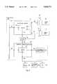
- FIG. 1A typical system of the prior art, including PCMCIA capability, is illustrated in FIG. 1.
- the main printed circuit board or motherboard 100includes the central processing unit (CPU) 126 which controls the operations of the computer system and also the internal system memory 128.
- the CPU 126is coupled to the system memory 128 and the other integrated circuits on the motherboard 100 by the core logic 124 and the system bus 140.
- the PCMCIA Host Adapter integrated circuit 110is coupled as the interface between the system bus 140 and the PCMCIA expansion slots 112 and 114 in order to control communications between the PCMCIA expansion slots 112 and 114 and the system bus 140.
- the PCMCIA Host Adapter integrated circuit 110is coupled to the PCMCIA expansion slot 112 by the PCMCIA interface bus 120 and to the PCMCIA expansion slot 114 by the PCMCIA interface bus 122.
- the PCMCIA host adapter integrated circuit 110controls and directs communications between the peripherals coupled to the PCMCIA expansion slots 112 and 114 and the system bus 140.
- the system bus 140has a differing number of address and data lines as compared to the address and data line requirements of the PCMCIA interface busses 120 and 122. Data transfers across the system bus 140 are at a different rate than the data transfer to a PCMCIA card 116 or 118. Other control signals, not included on the system bus 140, are also required at the PCMCIA interface in order to adapt to the various needs of differing types of PCMCIA cards that may be inserted. Thus, the PCMCIA interface is very flexible and the PCMCIA host adapter integrated circuit 110 is used to interface differing data and address line requirements having different transfer rates between the system bus 140 and the PCMCIA cards 116 or 118.
- the PCMCIA expansion slots 112 and 114are two typical implementations of sockets, also referred to as slots, into which a PCMCIA card 116 or 118 can be inserted.
- the PCMCIA standardenables memory and input/output (I/O) devices to be inserted as exchangeable peripherals into electronic devices through a standard interface.
- a PCMCIA card 116uses this standard interface, allowing PCMCIA interfaced peripheral devices such as a modem card, a network card, a sound card, a floppy disk drive, a hard disk drive, or other cards to be plugged into the system computer by means of their embodiment in a PCMCIA card 116.
- This PCMCIA card 116is plugged into a PCMCIA expansion slot 112 which is coupled to a PCMCIA host adapter integrated circuit 110 within the computer system.
- the operation of the PCMCIA expansion slot 112is controlled by the PCMCIA host adapter integrated circuit 110.
- the graphics controller 134is included on the motherboard 100.
- the graphics controller 134is coupled to the system bus 140 and to the output display used by the portable computer system, by either of the outputs 136 or 138. If the output display used by the portable computer system is a CRT display then the RGB output 136 of the graphics controller 134 is coupled to the display. If the output display used by the portable computer system is a flat-panel display then the flat-panel output 138 of the graphics controller 134 is coupled to the display.
- What is neededis a method to couple a multimedia type PCMCIA peripheral card over a standard PCMCIA interface.
- a PCMCIA host adapter integrated circuitwhich will couple a multimedia type PCMCIA peripheral card directly to the graphics controller, thereby bypassing the host system bus and allowing the host system bus to simultaneously be utilized for communications between other system components.
- a computer system including one or more PCMCIA expansion slotsallows video and/or audio capabilities to be added to the system through a standard PCMCIA interface, utilizing multimedia type PCMCIA peripheral cards.
- a PCMCIA host adapter integrated circuitinterrogates a PCMCIA peripheral card to determine whether or not the PCMCIA peripheral card is a multimedia type PCMCIA peripheral including video or audio capability. If the PCMCIA peripheral card is a multimedia type peripheral, the PCMCIA host adapter integrated circuit couples the PCMCIA peripheral card directly to the graphics and sound controller integrated circuits, using the standard PCMCIA interface and bypassing the host system bus.
- the PCMCIA host adapter integrated circuitinterfaces communications between the PCMCIA peripheral card and the host system bus in a conventional manner.
- the computer systemincludes a multi-windowing or display function whereby a typical computer applications program may be operating and displayed in a first window or display while the system simultaneously displays a playback or live video signal from a multimedia type peripheral card in a second window or display.
- FIG. 1illustrates a block diagram schematic of a typical computer system of the prior art including PCMCIA capability.
- FIG. 2illustrates a block diagram schematic of the system of the present invention.
- FIG. 3illustrates a block diagram schematic of the arbiter circuit of the present invention.
- FIG. 4illustrates a block diagram schematic of the switching circuit of the present invention.
- FIG. 5illustrates a block diagram schematic of an alternate embodiment of the switching circuit.
- the present inventionallows video and audio capability to be added to a host computer system over a standard PCMCIA interface.
- a multimedia type PCMCIA peripheral cardmay be plugged into a standard PCMCIA expansion slot.
- a multimedia type PCMCIA peripheral cardincludes video and/or audio capability, such as a television tuner, an NTSC decoder, a VCR controller and the like.
- the necessary video, audio and control signalsare multiplexed onto the PCMCIA bus which couples the PCMCIA socket to the PCMCIA host adapter.
- the PCMCIA host adapteris modified so that it will directly route the video, audio and control signals directly to the output display, the output audio circuits and the output control circuits, effectively bypassing the host system bus, when a multimedia type PCMCIA card having video or audio capability is plugged into the PCMCIA socket.
- the PCMCIA host adapter of the present inventioninterfaces between the peripheral and the host system bus in a conventional manner.
- the motherboard 200includes a PCMCIA host adapter 210 which is capable of interfacing between the PCMCIA cards 216 and 218 and either the host system bus 240, through the bi-directional connector bus 262, or the graphics and sound controller 234 through the bi-directional connector bus 248, depending on the type of peripheral coupled to the PCMCIA cards 216 and 218.
- the PCMCIA host adapter 210is coupled to the PCMCIA expansion slot 212 by the bi-directional PCMCIA bus 220.
- the PCMCIA host adapter 210is coupled to the PCMCIA expansion slot 214 by the bi-directional PCMCIA bus 222.
- a single PCMCIA busmay be used to couple both of the PCMCIA expansion slots 212 and 214 to the PCMCIA host adapter 210.
- the PCMCIA host adapter 210is coupled to the host system bus 240 through the bi-directional connector bus 262.
- the PCMCIA host adapter 210is also coupled to the graphics and sound controller 234 by the bi-directional connector bus 248.
- the graphics and sound controller 234is coupled to the host system bus 240 through the bi-directional connector bus 258.
- the graphics and sound controller 234is also coupled to the video/graphics memory buffer 250 through the bi-directional connector bus 260.
- the graphics and sound controller 234is further coupled to control at least one output display by the display control bus 246.
- the output displaymay be a CRT monitor 252, a flat panel display 254, a television 256 or any other appropriate device which is apparent to one skilled in the art.
- the PCMCIA host adapter 210interrogates the PCMCIA card 216 in order to determine what type of peripheral is coupled to the PCMCIA card 216.
- the interrogation of the PCMCIA card 216is conducted using existing PCMCIA configuration methods including CPU interrogation of the PCMCIA card information structure and determining the levels present on the card detect and voltage select signal lines, as described in the PCMCIA standard specifications.
- the PCMCIA host adapter 210serves as an interface between the peripheral and the host system bus 240 in a conventional manner, thereby interfacing communications between the host system bus 240 and the PCMCIA card 216 using the appropriate transfer rates and data and address line requirements. If the peripheral coupled to the PCMCIA card 216 is a multimedia type PCMCIA peripheral and does include video or audio capabilities, the PCMCIA host adapter 210 routes a selected group of dual purpose signals from the PCMCIA standard interface, directly between the PCMCIA card 216 and the graphics and sound controller 234, thereby bypassing the host system bus 240.
- the host system bus 240is also coupled to the graphics and sound controller 234 for outputting data to an output display 252, 254 or 256, as is well known in the art.
- the arbiter circuit 242 within the PCMCIA host adapter 210will be programmed by the CPU after the card information structure has been read and will then direct communications between the peripheral, the host system bus 240 and the graphics and sound controller 234, as required.
- a detailed schematic of the arbiter circuit 242 of the preferred embodimentis illustrated in FIG. 3.
- the PCMCIA bus 220is coupled to the switching circuit 302.
- the switching circuit 302is coupled to the host system bus interface circuit 306 by the bi-directional bus 310 for interfacing between the PCMCIA bus 220 and the host system bus 240 in a conventional manner, when a standard PCMCIA peripheral is coupled to the PCMCIA slot 212.
- the switching circuit 302is also coupled directly to the display and audio interface circuit 308 by the bi-directional bus 312 for interfacing directly between the PCMCIA bus 220 and the graphics and sound controller 234 when a multi-media type peripheral is coupled to the PCMCIA slot 212.
- the PCMCIA bus 222is coupled to the switching circuit 304.
- the switching circuit 304is coupled to the host system bus interface circuit 306 by the bi-directional bus 314 for interfacing between the PCMCIA bus 222 and the host system bus 240 in a conventional manner, when a standard PCMCIA peripheral is coupled to the PCMCIA slot 214.
- the switching circuit 304is also coupled directly to the display and audio interface circuit 308 by the bi-directional bus 316 for interfacing directly between the PCMCIA bus 222 and the graphics and sound controller 234 when a multi-media type peripheral is coupled to the PCMCIA slot 214.
- the control logic block 300is coupled to the switching circuit 302, to the switching circuit 304, to the host system bus interface circuit 306 and to the display and audio interface circuit 308 for interfacing and controlling communications to and from the PCMCIA busses 220 and 222.
- the host system bus interface circuitis coupled to the host system bus 240 by the bus 262.
- the display and audio interface circuitis coupled to the graphics and sound controller 234 by the connector bus 248.
- the control logic block 300is responsible for interrogating the PCMCIA cards 216 and 218 when a new PCMCIA card is plugged into the PCMCIA slots 212 and 214 or upon system reset, in order to determine what type of peripheral is coupled to the PCMCIA cards 216 and 218. Once the control logic block 300 has determined what type of peripheral is coupled to the PCMCIA cards 216 and 218, it then determines whether communications to and from the PCMCIA busses 220 and 222 should be directed to the host system bus interface circuit 306 or directly to the display and audio interface circuit 308.
- control logic block 300determines that the peripheral coupled to the PCMCIA card 216 is a standard peripheral, the control logic block 300 notifies the switching circuit 302 that communications to and from that peripheral should be directed between the PCMCIA bus 220 and the host system bus interface circuit 306. If the control logic block 300 determines that the peripheral coupled to the PCMCIA card 216 is a multi-media type peripheral, including audio or video capabilities, the control logic block notifies the switching circuit 302 that communications to and from that peripheral should be directed between the PCMCIA bus 220 and the display and audio interface circuit 308 directly.
- control logic block 300If the control logic block 300 has been programmed to handle the peripheral coupled to the PCMCIA card 218 as a standard peripheral, the control logic block 300 notifies the switching circuit 304 that communications to and from that peripheral should be directed between the PCMCIA bus 222 and the host system bus interface circuit 306. If the control logic block 300 has been programmed to handle the peripheral coupled to the PCMCIA card 216 as a multi-media type peripheral, including audio and/or video capabilities, the control logic block 300 notifies the switching circuit 304 that communications to and from that peripheral should be directed between the PCMCIA bus 222 and the display and audio interface circuit 308 directly.
- the switching circuit 302includes input/output analog switches, as illustrated in FIG. 4.
- the switching circuit 304is identical to the switching circuit 302 except that it is coupled to the PCMCIA bus 222 and to the bi-directional busses 314 and 316.
- the switching circuits 302 and 304may be implemented in any appropriate manner, as will be apparent to those skilled in the art, including a logic gate or combination of gates.
- a standard PCMCIA expansion slotsuch as the slots 212 and 214, has a total of 68 pins which are each coupled to the PCMCIA bus 220 or 222 and to a PCMCIA card 216 or 218 which is plugged into the slot 212 or 214.
- the switching circuit 302allows 24 of the standard PCMCIA pins to serve a dual purpose, depending on the type of PCMCIA card 216 which is plugged into the PCMCIA slot 212. If the PCMCIA card 216 is a standard PCMCIA card, then the control logic block 300 directs the switching circuit 400 to couple the dual purpose pins to their standard connection on the bus 310 which communicates with the host system bus 240.
- the control logic block 300directs the switching circuit 400 to couple the dual purpose pins to their multimedia connection on the bus 312 which communicates with the graphics and sound controller 234.
- the remaining pins within the PCMCIA slot 212which do not serve a dual purpose according to the present invention, are always coupled to the bus 310 for communication with the host system bus 240.
- control logic block 300is coupled to each of the switches within the switching circuit 400 for controlling the operation of each of the switches within the switching circuit 400, simultaneously.
- the pin 8is coupled to the address line A10.
- the switch coupled to the pin 8switches between the address line A10 and the multimedia control signal line C5, as directed by the control logic block 300.
- the pin 10is coupled to the address line A11.
- the switch coupled to the pin 10switches between the address line All and the multimedia control signal line C4, as directed by the control logic block 300.
- the pin 11is coupled to the address line A9.
- the switch coupled to the pin 11switches between the address line A9 and the video data signal line D0, as directed by the control logic block 300.
- the pin 12ms coupled to the address line A8.
- the switch coupled to the pin 12switches between the address line A8 and the video data signal line D2, as directed by the control logic block 300.
- the pin 13ms coupled to the address line A13.
- the switch coupled to the pin 13switches between the address line A13 and the video data signal line D4, as directed by the control logic block 300.
- the pin 14ms coupled to the address line A14.
- the switch coupled to the pin 14switches between the address line A14 and the video data signal line D6, as directed by the control logic block 300.
- the pin 19ms coupled to the address line A16.
- the switch coupled to the pin 19switches between the address line A16 and the video data signal line D10, as directed by the control logic block 300.
- the pin 20ms coupled to the address line A15.
- the switch coupled to the pin 20switches between the address line A15 and the video data signal line D12, as directed by the control logic block 300.
- the pin 21ms coupled to the address line A12.
- the switch coupled to the pin 21switches between the address line A12 and the video data signal line D14, as directed by the control logic block 300.
- the pin 22is coupled to the address line A7.
- the switch coupled to the pin 22switches between the address line A7 and the multimedia control signal line C3, as directed by the control logic block 300.
- the pin 23is coupled to the address line A6.
- the switch coupled to the pin 23switches between the address line A6 and the audio data signal line S1, as directed by the control logic block 300.
- the pin 24is coupled to the address line A5.
- the switch coupled to the pin 24switches between the address line A5 and the multimedia control signal line C2, as directed by the control logic block 300.
- the pin 25is coupled to the address line A4.
- the switch coupled to the pin 25switches between the address line A4 and the multimedia control signal line C1, as directed by the control logic block 300.
- the pin 33is coupled to the write protect signal line WP.
- the switch coupled to the pin 33switches between the write protect signal line WP and the audio data signal line S0, as directed by the control logic block 300.
- the pin 46is coupled to the address line A17.
- the switch coupled to the pin 46switches between the address line A17 and the video data signal line D1, as directed by the control logic block 300.
- the pin 47is coupled to the address line A18.
- the switch coupled to the pin 47switches between the address line A18 and the video data signal line D3, as directed by the control logic block 300.
- the pin 48ms coupled to the address line A19 Within the switching circuit 302, the switch coupled to the pin 48 switches between the address line A19 and the video data signal line D1, as directed by the control logic block 300.
- the pin 49is coupled to the address line A20 Within the switching circuit 302, the switch coupled to the pin 49 switches between the address line A20 and the video data signal line D7, as directed by the control logic block 300.
- the pin 50is coupled to the address line A21.
- the switch coupled to the pin 50switches between the address line A21 and the video data signal line D8, as directed by the control logic block 300.
- the pin 53is coupled to the address line A22.
- the switch coupled to the pin 53switches between the address line A22 and the video data signal line D9, as directed by the control logic block 300.
- the pin 54ms coupled to the address line A23.
- the switch coupled to the pin 54switches between the address line A23 and the video data signal line D11, as directed by the control logic block 300.
- the pin 55is coupled to the address line A24.
- the switch coupled to the pin 55switches between the address line A24 and the video data signal line D13, as directed by the control logic block 300.
- the pin 60is coupled to a reserved signal line RFU.
- the switch coupled to the pin 60switches between the reserved signal line RFU and the multimedia control signal line C0, as directed by the control logic block 300.
- the address lines A4-A25, the reserved signal line RFU and the write protect signal line WPare all coupled to the bus 310 for communication with the host system bus 240, when directed by the control logic block 300.
- the multimedia control signal lines C0-C5, the video data signal lines D0-D15 and the audio data signal lines S0 and S1are all coupled to the bus 312 for communication with the graphics and sound controller 234.
- the switching circuit 304has not been described in detail, its couplings and operation are identical to that of the switching circuit 302, described above, except that the switching circuit 304 is coupled to the PCMCIA bus 222 for communications with the PCMCIA slot 214, to the bus 314 for communications with the host system bus 240 and to the bus 316 for communications with the graphics and sound controller 234.
- the operation of the switching circuit 304is identical to that described above for the switching circuit 302.
- the switches used within the switching circuits 302 and 304may be of any appropriate design which conforms to the constraints of the particular design environment.
- the switching circuit 304is external to the PCMCIA adapter 210, as illustrated in FIG. 5.
- the PCMCIA card 218, when identified as a multimedia card,is coupled to the PCMCIA bus 222 and thereby coupled to the graphics and sound controller 234 either directly or through the tri-state isolation buffers 501.
- the tri-state isolation buffers 501are designed to implement the switching circuit 304 and are controlled either by the arbiter circuit 242 through the logic signal line 502 or an external control circuit through the host system bus 240.
- the arbiter circuit 242When the arbiter circuit 242 is controlling the tri-state buffers 501, the arbiter circuit 242, on command from the CPU over the host system bus 240 and the bi-directional connector bus 262, will control the operation of the tri-state buffers 501 through the logic signal line 502 and thereby facilitate communication directly between the expansion slot 214 and the graphics and sound controller 234.
- the PCMCIA host adapter 210under program control, will place the assigned pins in a high impedance state to facilitate the transfer of multimedia data over the PCMCIA bus 222 to the tri-state isolation buffers 501 and then to the graphics and sound controller 234 or directly to the graphics and sound controller 234.
- the communicationsare directed through the arbiter circuit 242, as described above.
- the PCMCIA slot 212may also be coupled to an external set of tri-state buffers for direct communication with the graphics and sound controller 234 when a multimedia type PCMCIA card is plugged into the PCMCIA expansion slot 212, in the same manner as illustrated in FIG. 5.
- the PCMCIA host adapter 210Upon power-on reset or when a new PCMCIA card 216 or 218 is plugged into one of the PCMCIA slots 212 or 214, the PCMCIA host adapter 210 interrogates the PCMCIA cards 216 and 218 in order to determine what type of peripheral is coupled to each of the PCMCIA cards 216 and 218. If the peripheral coupled to the PCMCIA card 216 is a standard PCMCIA peripheral, then the control logic block 300 directs the switching circuit 302 to couple the dual purpose pins coupled within the switching circuit 302 to their standard connections and thereby to the bus 310 for communication with the host system bus 240 through the host system bus interface circuit 306.
- the control logic block 300directs the switching circuit 302 to couple the dual purpose pins coupled within the switching circuit 302 to their multimedia connections and thereby to the bus 312 for communication with the graphics and sound controller 234, through the display and audio interface circuit 308.
- the control logic block 300directs the switching circuit 304, to couple the dual purpose pins coupled within the switching circuit 304 to their standard connections and thereby to the bus 314 for communication with the host system bus 240 through the host system bus interface circuit 306.
- the control logic block 300directs the switching circuit 304 to couple the dual purpose pins coupled within the switching circuit 304 to their multimedia connections and thereby to the bus 316 for communication with the graphics and sound controller 234, through the display and audio interface circuit 308.
- the control logic block 300When more than one PCMCIA peripheral card 216 and 218 is coupled to the system, the control logic block 300 must multiplex and control communications to and from the PCMCIA cards 216 and 218. Within the arbiter circuit 242 of the present invention, the switching circuits 302 and 304 are maintained separately by the control logic block 300 in order to accommodate PCMCIA peripheral cards of differing formats.
- the PCMCIA card 216may be a standard format PCMCIA peripheral card and require communications with the host system bus 240 while the PCMCIA card 218 may be a multimedia type PCMCIA peripheral card and require communications with the graphics and sound controller 234 directly, or vice versa.
- the control logic block 300must control these communications and route them accordingly.
- the host system bus interface circuit 306is controlled by the control logic block 300.
- the control logic block 300will notify the host system bus interface circuit 306 which one of the PCMCIA peripheral cards desires communications with the host system bus 240.
- the host system bus interface circuit 306will couple the appropriate bi-directional bus 310 or 314 to the host system bus 240, through the connector bus 262, in a conventional manner.
- the display and audio interface circuit 308is controlled by the control logic block 300.
- the control logic block 300will notify the display and audio interface circuit 308 which one of the PCMCIA peripheral cards desires communications with the host system bus 240.
- the display and audio interface circuit 308will couple the appropriate bi-directional bus 312 or 316 to the graphics and sound controller 234, through the connector bus 248.
- the PCMCIA host adapter circuit 210 of the present inventioncouples video data signals, audio data signals and control data signals directly from the PCMCIA bus 220 or 222 to the graphics and sound controller 234, over a standard PCMCIA interface, effectively bypassing the host system bus 240.
- a PCMCIA card 216 or 218to add video and/or audio capabilities, this method does not require the addition of any planar logic on the motherboard 200.
- the system of the present inventionalso does not rely on the host system bus bandwidth capabilities to ensure high quality live video capability on the output display 252, 254 or 256. Using this method and bypassing the system bus allows a system to decrease system bus activity while displaying full screen live video, thereby greatly reducing the system power requirements. For a portable computer system, this will mean longer battery life.
- This method of the present inventionwill allow a portable computer to function as a television either while a user simultaneously works on an application or with most of the system in a stand-by mode. If the user is not simultaneously working on an application while the system is displaying video, the only major subsystems which will require full operational power are the PCMCIA host adapter 210, the PCMCIA multimedia peripheral coupled to the PCMCIA card 216 or 218, the graphics and sound controller 234 and the appropriate output display 252, 254 or 256.
- the host system bus 240is also coupled directly to the graphics and sound controller circuit 234 for communicating to the system output display 252, 254 or 256. If the system output display 252, 254 or 256 is capable, and the user so desires, the graphics and sound controller circuit 234 of the present invention will direct the system output display 252, 254 or 256 to display two windows on the display screen, if a multimedia type PCMCIA peripheral is coupled to the system. Alternatively, two separate output displays 252, 254 or 256 may be utilized. In either of these ways, a user may utilize the typical computer functions of the system in the window or display driven by the host system bus 240 while simultaneously utilizing other multimedia type functions in the window or display controlled by the multimedia type PCMCIA card.
- the system of the present inventionwill therefore allow a user to work on a typical computer application such as word-processing, spreadsheet, data base, or the like, while at the same time watching a television show or video feed and listening to the accompanying audio signal.
- a usermay conduct a video teleconference with a person at another location, whereby the two persons may communicate electronically and simultaneously edit a computer file, such as a word-processing document, while at the same time communicating over a shared live video and audio feed.
- a system of the present invention including two PCMCIA expansion slots 212 and 214may incorporate two multimedia type peripherals, two standard PCMCIA peripherals or one multimedia type peripheral and one standard PCMCIA peripheral. In this manner, a user is allowed maximum flexibility to configure the system as desired.
- the PCMCIA host adapter 210will selectively couple the PCMCIA busses 220 and 222 to either the host system bus 240 or the graphics and sound controller 234, as appropriate.
Landscapes
- Engineering & Computer Science (AREA)
- Theoretical Computer Science (AREA)
- Physics & Mathematics (AREA)
- General Engineering & Computer Science (AREA)
- General Physics & Mathematics (AREA)
- Human Computer Interaction (AREA)
- Multimedia (AREA)
- Health & Medical Sciences (AREA)
- Audiology, Speech & Language Pathology (AREA)
- General Health & Medical Sciences (AREA)
- Digital Computer Display Output (AREA)
Abstract
Description
Claims (15)
Priority Applications (1)
| Application Number | Priority Date | Filing Date | Title |
|---|---|---|---|
| US08/383,582US5630174A (en) | 1995-02-03 | 1995-02-03 | Adapter for detecting whether a peripheral is standard or multimedia type format and selectively switching the peripheral to couple or bypass the system bus |
Applications Claiming Priority (1)
| Application Number | Priority Date | Filing Date | Title |
|---|---|---|---|
| US08/383,582US5630174A (en) | 1995-02-03 | 1995-02-03 | Adapter for detecting whether a peripheral is standard or multimedia type format and selectively switching the peripheral to couple or bypass the system bus |
Publications (1)
| Publication Number | Publication Date |
|---|---|
| US5630174Atrue US5630174A (en) | 1997-05-13 |
Family
ID=23513786
Family Applications (1)
| Application Number | Title | Priority Date | Filing Date |
|---|---|---|---|
| US08/383,582Expired - LifetimeUS5630174A (en) | 1995-02-03 | 1995-02-03 | Adapter for detecting whether a peripheral is standard or multimedia type format and selectively switching the peripheral to couple or bypass the system bus |
Country Status (1)
| Country | Link |
|---|---|
| US (1) | US5630174A (en) |
Cited By (65)
| Publication number | Priority date | Publication date | Assignee | Title |
|---|---|---|---|---|
| US5708853A (en)* | 1995-07-24 | 1998-01-13 | Mitsubishi Denki Kabushiki Kaisha | IC card having camera, microphone, and modem for use in information processors |
| US5748913A (en)* | 1996-02-29 | 1998-05-05 | Kabushiki Kaisha Toshiba | Computer system capable of transferring video data between card devices |
| US5754796A (en)* | 1996-05-07 | 1998-05-19 | Wang; Daniel | Bus port transmission device |
| US5757432A (en)* | 1995-12-18 | 1998-05-26 | Intel Corporation | Manipulating video and audio signals using a processor which supports SIMD instructions |
| US5758099A (en)* | 1996-05-29 | 1998-05-26 | International Business Machines Corporation | Plug and play protocol for bus adapter card |
| US5787019A (en)* | 1996-05-10 | 1998-07-28 | Apple Computer, Inc. | System and method for handling dynamic changes in device states |
| US5815421A (en)* | 1995-12-18 | 1998-09-29 | Intel Corporation | Method for transposing a two-dimensional array |
| US5841994A (en)* | 1996-06-14 | 1998-11-24 | Texas Instruments Incorporated | Portable computer with multiple zoom port interface |
| WO1998055912A1 (en)* | 1997-06-04 | 1998-12-10 | Spyrus, Inc. | Modular security device |
| WO1998055911A1 (en)* | 1997-06-04 | 1998-12-10 | Spyrus, Inc. | Peripheral device with integrated security functionality |
| US5883613A (en)* | 1996-03-01 | 1999-03-16 | Kabushiki Kaisha Toshiba | Moving pictures display system |
| EP0917064A1 (en)* | 1997-11-18 | 1999-05-19 | Shuttle Technology Limited | Memory card interface apparatus |
| US5907686A (en)* | 1994-06-06 | 1999-05-25 | Kabushiki Kaisha Toshiba | Display control system having a PCMCIA interface |
| US5935228A (en)* | 1996-04-26 | 1999-08-10 | International Business Machines Corporation | Method for automatically enabling peripheral devices and a storage medium for storing automatic enable program for peripheral devices |
| US6044423A (en)* | 1996-11-13 | 2000-03-28 | Samsung Electronics Co., Ltd. | Identification of a swappable device in a portable computer |
| US6119178A (en)* | 1997-11-25 | 2000-09-12 | 8×8 Inc. | Communication interface between remote transmission of both compressed video and other data and data exchange with local peripherals |
| US6141021A (en)* | 1997-12-12 | 2000-10-31 | Intel Corporation | Method and apparatus for eliminating contention on an accelerated graphics port |
| WO2000079403A3 (en)* | 1999-06-17 | 2001-08-02 | Livetoy Networks Inc | Pluggable device for controlling interconnected circuits |
| US20010027032A1 (en)* | 2000-03-01 | 2001-10-04 | Yuichi Inomata | Mode-switchable PC card and PC card input/output control device |
| US6330622B1 (en)* | 1998-10-23 | 2001-12-11 | Intel Corporation | Direct processor access via an external multi-purpose interface |
| US20020069252A1 (en)* | 2000-07-10 | 2002-06-06 | Songpro.Com, Inc. | Personal multimedia device and methods of use thereof |
| US20020083220A1 (en)* | 2000-12-26 | 2002-06-27 | Tadahiro Ushiro | Microcomputer |
| US6473822B1 (en)* | 1998-05-13 | 2002-10-29 | Sony Corporation | Digital signal processing apparatus |
| US6502159B1 (en)* | 1996-06-21 | 2002-12-31 | Acer Incorporated | Method and apparatus for increasing data throughput in a computer system |
| WO2002095557A3 (en)* | 2001-05-18 | 2003-02-06 | Ubinetics Ltd | A method of data communication between a host computer and a pc card modem |
| US20030056225A1 (en)* | 2001-09-18 | 2003-03-20 | Bione Angelo A. | Remote control method and system for operating devices served by a modular multi-media converged services portal |
| US20030061424A1 (en)* | 2001-09-26 | 2003-03-27 | Leete Brian A. | Method and apparatus for dual queue head processing of interrupt endpoints |
| US6542938B1 (en) | 1997-12-23 | 2003-04-01 | Seiko Epson Corporation | Mechanism and apparatus for adaptive quality performance control in 3D based PC applications |
| US20030084227A1 (en)* | 2001-10-26 | 2003-05-01 | Huang Yishao Max | PCI-PCMCIA smart card reader |
| US6558049B1 (en)* | 1996-06-13 | 2003-05-06 | Texas Instruments Incorporated | System for processing video in computing devices that multiplexes multiple video streams into a single video stream which is input to a graphics controller |
| US20030097350A1 (en)* | 2001-11-06 | 2003-05-22 | Shamrao Andrew Divaker | Handheld computer systems and methods |
| US6598095B2 (en)* | 1999-04-14 | 2003-07-22 | Micron Technology, Inc. | Method and system for identifying and configuring peripheral devices |
| US6609977B1 (en) | 2000-08-23 | 2003-08-26 | Nintendo Co., Ltd. | External interfaces for a 3D graphics system |
| US20030212735A1 (en)* | 2002-05-13 | 2003-11-13 | Nvidia Corporation | Method and apparatus for providing an integrated network of processors |
| US20040114589A1 (en)* | 2002-12-13 | 2004-06-17 | Alfieri Robert A. | Method and apparatus for performing network processing functions |
| US20040122992A1 (en)* | 2002-12-24 | 2004-06-24 | Scott Janus | Detection of support components for add-in card |
| US6771664B1 (en) | 1999-12-28 | 2004-08-03 | Intel Corporation | Transaction scheduling for a bus system in a multiple speed environment |
| US6772265B2 (en)* | 2000-12-11 | 2004-08-03 | International Business Machines Corporation | Docking station for a laptop computer |
| US20040181617A1 (en)* | 2003-03-11 | 2004-09-16 | Dell Products L.P. | System and method for using a switch to route peripheral and graphics data on an interconnect |
| US6813251B1 (en)* | 1999-07-27 | 2004-11-02 | Intel Corporation | Split Transaction protocol for a bus system |
| US20050143128A1 (en)* | 2003-12-08 | 2005-06-30 | Katsutoshi Sakao | Communication card |
| EP1557750A1 (en) | 2004-01-23 | 2005-07-27 | Genesis Microchip, Inc. | Low power DVD playback in a portable computing system |
| US20050165986A1 (en)* | 2004-01-24 | 2005-07-28 | Tai-Cheng Wang | Console chip and one-bus system |
| US20050183014A1 (en)* | 2004-02-18 | 2005-08-18 | Yung-Da Lin | Audio-video signal transceiving processing device |
| US7003588B1 (en) | 2001-08-22 | 2006-02-21 | Nintendo Co., Ltd. | Peripheral devices for a video game system |
| EP1182572A3 (en)* | 2000-08-25 | 2006-03-22 | Samsung Electronics Co., Ltd. | Multimedia modular card, device for operating the same, and integrated multimedia system |
| US20060145735A1 (en)* | 2003-07-14 | 2006-07-06 | Kazuo Sakamoto | Output buffer circuit eliminating high voltage insulated transistor and level shift circuit, and an interface circuit using the output buffer circuit |
| US7134960B1 (en) | 2000-08-23 | 2006-11-14 | Nintendo Co., Ltd. | External interfaces for a 3D graphics system |
| US20070180177A1 (en)* | 2000-07-06 | 2007-08-02 | Onspec Electronic, Inc. | Flashtoaster for reading several types of flash-memory cards with or without a PC |
| US20070233907A1 (en)* | 2004-09-28 | 2007-10-04 | Zentek Technology Japan, Inc, | Host Controller |
| US20070288677A1 (en)* | 2000-07-06 | 2007-12-13 | Onspec Electronic, Inc. | Field-Operable, Stand-Alone Apparatus for Media Recovery and Regeneration |
| US20080017718A1 (en)* | 2000-07-06 | 2008-01-24 | Onspec Electronic, Inc. | Memory Module Which Includes a Form Factor Connector |
| US20080299809A1 (en)* | 2000-07-06 | 2008-12-04 | Mcm Portfolio Llc | Smartconnect flash card adapter |
| CN100445931C (en)* | 2004-02-20 | 2008-12-24 | 圆刚科技股份有限公司 | Sound image signal transmitting and receiving processor |
| US20090027365A1 (en)* | 2007-07-23 | 2009-01-29 | Samsung Electronics Co., Ltd. | Display apparatus and control method thereof |
| US7493437B1 (en)* | 2000-07-06 | 2009-02-17 | Mcm Portfolio Llc | Flashtoaster for reading several types of flash memory cards with or without a PC |
| CN101542629A (en)* | 2006-07-07 | 2009-09-23 | S.阿夸半导体有限公司 | Memory using front-end precharge |
| DE19882925B4 (en)* | 1997-12-31 | 2010-04-01 | Intel Corporation, Santa Clara | Video processing system for high speed video applications on computer processor with components connected by PCI bus e.g. for video conferencing |
| US20100191879A1 (en)* | 2009-01-28 | 2010-07-29 | Sandisk Il Ltd. | Host-peripheral adaptor |
| US7782328B1 (en)* | 1998-03-24 | 2010-08-24 | Ati Technologies Ulc | Method and apparatus of video graphics and audio processing |
| US7913294B1 (en) | 2003-06-24 | 2011-03-22 | Nvidia Corporation | Network protocol processing for filtering packets |
| US20110125960A1 (en)* | 2006-07-28 | 2011-05-26 | Drc Computer Corporation | FPGA Co-Processor For Accelerated Computation |
| US10084985B2 (en)* | 2016-07-26 | 2018-09-25 | Beijing Xiaomi Mobile Software Co., Ltd. | Display device and mainboard applied in the display device |
| US10963408B2 (en)* | 2017-06-01 | 2021-03-30 | University Of Virginia Patent Foundation | System on a chip with customized data flow architecture |
| US20240256480A1 (en)* | 2023-01-26 | 2024-08-01 | Dell Products L.P. | System and method for connecting devices having variable form factors to data processing systems |
Citations (8)
| Publication number | Priority date | Publication date | Assignee | Title |
|---|---|---|---|---|
| US4855813A (en)* | 1987-12-11 | 1989-08-08 | Russell David P | Television image processing system having capture, merge and display capability |
| US5335321A (en)* | 1992-06-19 | 1994-08-02 | Intel Corporation | Scalable multimedia platform architecture |
| US5392407A (en)* | 1992-12-24 | 1995-02-21 | Ncr Corporation | Multi-port processor with peripheral component interconnect port and rambus port |
| US5396602A (en)* | 1993-05-28 | 1995-03-07 | International Business Machines Corp. | Arbitration logic for multiple bus computer system |
| US5402147A (en)* | 1992-10-30 | 1995-03-28 | International Business Machines Corporation | Integrated single frame buffer memory for storing graphics and video data |
| US5428730A (en)* | 1992-12-15 | 1995-06-27 | International Business Machines Corporation | Multimedia system having software mechanism providing standardized interfaces and controls for the operation of multimedia devices |
| US5467452A (en)* | 1992-07-17 | 1995-11-14 | International Business Machines Corporation | Routing control information via a bus selectively controls whether data should be routed through a switch or a bus according to number of destination processors |
| US5473342A (en)* | 1993-10-19 | 1995-12-05 | Chrontel, Inc. | Method and apparatus for on-the-fly multiple display mode switching in high-resolution bitmapped graphics system |
- 1995
- 1995-02-03USUS08/383,582patent/US5630174A/ennot_activeExpired - Lifetime
Patent Citations (8)
| Publication number | Priority date | Publication date | Assignee | Title |
|---|---|---|---|---|
| US4855813A (en)* | 1987-12-11 | 1989-08-08 | Russell David P | Television image processing system having capture, merge and display capability |
| US5335321A (en)* | 1992-06-19 | 1994-08-02 | Intel Corporation | Scalable multimedia platform architecture |
| US5467452A (en)* | 1992-07-17 | 1995-11-14 | International Business Machines Corporation | Routing control information via a bus selectively controls whether data should be routed through a switch or a bus according to number of destination processors |
| US5402147A (en)* | 1992-10-30 | 1995-03-28 | International Business Machines Corporation | Integrated single frame buffer memory for storing graphics and video data |
| US5428730A (en)* | 1992-12-15 | 1995-06-27 | International Business Machines Corporation | Multimedia system having software mechanism providing standardized interfaces and controls for the operation of multimedia devices |
| US5392407A (en)* | 1992-12-24 | 1995-02-21 | Ncr Corporation | Multi-port processor with peripheral component interconnect port and rambus port |
| US5396602A (en)* | 1993-05-28 | 1995-03-07 | International Business Machines Corp. | Arbitration logic for multiple bus computer system |
| US5473342A (en)* | 1993-10-19 | 1995-12-05 | Chrontel, Inc. | Method and apparatus for on-the-fly multiple display mode switching in high-resolution bitmapped graphics system |
Cited By (120)
| Publication number | Priority date | Publication date | Assignee | Title |
|---|---|---|---|---|
| US5907686A (en)* | 1994-06-06 | 1999-05-25 | Kabushiki Kaisha Toshiba | Display control system having a PCMCIA interface |
| US5708853A (en)* | 1995-07-24 | 1998-01-13 | Mitsubishi Denki Kabushiki Kaisha | IC card having camera, microphone, and modem for use in information processors |
| US5815421A (en)* | 1995-12-18 | 1998-09-29 | Intel Corporation | Method for transposing a two-dimensional array |
| US5757432A (en)* | 1995-12-18 | 1998-05-26 | Intel Corporation | Manipulating video and audio signals using a processor which supports SIMD instructions |
| US5748913A (en)* | 1996-02-29 | 1998-05-05 | Kabushiki Kaisha Toshiba | Computer system capable of transferring video data between card devices |
| US5883613A (en)* | 1996-03-01 | 1999-03-16 | Kabushiki Kaisha Toshiba | Moving pictures display system |
| US5935228A (en)* | 1996-04-26 | 1999-08-10 | International Business Machines Corporation | Method for automatically enabling peripheral devices and a storage medium for storing automatic enable program for peripheral devices |
| US5754796A (en)* | 1996-05-07 | 1998-05-19 | Wang; Daniel | Bus port transmission device |
| US5787019A (en)* | 1996-05-10 | 1998-07-28 | Apple Computer, Inc. | System and method for handling dynamic changes in device states |
| US5758099A (en)* | 1996-05-29 | 1998-05-26 | International Business Machines Corporation | Plug and play protocol for bus adapter card |
| US6558049B1 (en)* | 1996-06-13 | 2003-05-06 | Texas Instruments Incorporated | System for processing video in computing devices that multiplexes multiple video streams into a single video stream which is input to a graphics controller |
| US5841994A (en)* | 1996-06-14 | 1998-11-24 | Texas Instruments Incorporated | Portable computer with multiple zoom port interface |
| US6502159B1 (en)* | 1996-06-21 | 2002-12-31 | Acer Incorporated | Method and apparatus for increasing data throughput in a computer system |
| US6044423A (en)* | 1996-11-13 | 2000-03-28 | Samsung Electronics Co., Ltd. | Identification of a swappable device in a portable computer |
| WO1998055911A1 (en)* | 1997-06-04 | 1998-12-10 | Spyrus, Inc. | Peripheral device with integrated security functionality |
| WO1998055912A1 (en)* | 1997-06-04 | 1998-12-10 | Spyrus, Inc. | Modular security device |
| US6003135A (en)* | 1997-06-04 | 1999-12-14 | Spyrus, Inc. | Modular security device |
| US6088802A (en)* | 1997-06-04 | 2000-07-11 | Spyrus, Inc. | Peripheral device with integrated security functionality |
| US5928347A (en)* | 1997-11-18 | 1999-07-27 | Shuttle Technology Group Ltd. | Universal memory card interface apparatus |
| US6145046A (en)* | 1997-11-18 | 2000-11-07 | Shuttle Technology Group Ltd. | Universal memory card interface apparatus |
| EP1139224A3 (en)* | 1997-11-18 | 2003-05-02 | SCM Microsystems Limited | Memory card interface apparatus |
| EP0917064A1 (en)* | 1997-11-18 | 1999-05-19 | Shuttle Technology Limited | Memory card interface apparatus |
| US6119178A (en)* | 1997-11-25 | 2000-09-12 | 8×8 Inc. | Communication interface between remote transmission of both compressed video and other data and data exchange with local peripherals |
| US6141021A (en)* | 1997-12-12 | 2000-10-31 | Intel Corporation | Method and apparatus for eliminating contention on an accelerated graphics port |
| US6542938B1 (en) | 1997-12-23 | 2003-04-01 | Seiko Epson Corporation | Mechanism and apparatus for adaptive quality performance control in 3D based PC applications |
| DE19882925B4 (en)* | 1997-12-31 | 2010-04-01 | Intel Corporation, Santa Clara | Video processing system for high speed video applications on computer processor with components connected by PCI bus e.g. for video conferencing |
| US7782328B1 (en)* | 1998-03-24 | 2010-08-24 | Ati Technologies Ulc | Method and apparatus of video graphics and audio processing |
| US6473822B1 (en)* | 1998-05-13 | 2002-10-29 | Sony Corporation | Digital signal processing apparatus |
| US6330622B1 (en)* | 1998-10-23 | 2001-12-11 | Intel Corporation | Direct processor access via an external multi-purpose interface |
| US6598095B2 (en)* | 1999-04-14 | 2003-07-22 | Micron Technology, Inc. | Method and system for identifying and configuring peripheral devices |
| WO2000079403A3 (en)* | 1999-06-17 | 2001-08-02 | Livetoy Networks Inc | Pluggable device for controlling interconnected circuits |
| US6813251B1 (en)* | 1999-07-27 | 2004-11-02 | Intel Corporation | Split Transaction protocol for a bus system |
| US20110099308A1 (en)* | 1999-07-27 | 2011-04-28 | Intel Corporation | Split transaction protocol for a bus system |
| US7675871B2 (en) | 1999-07-27 | 2010-03-09 | Intel Corporation | Split transaction protocol for a bus system |
| US9558142B2 (en) | 1999-07-27 | 2017-01-31 | Intel Corporation | Split transaction protocol for a bus system |
| US9892081B2 (en) | 1999-07-27 | 2018-02-13 | Intel Corporation | Split transaction protocol for a bus system |
| US20100169516A1 (en)* | 1999-07-27 | 2010-07-01 | Garney John I | Split transaction protocol for a bus system |
| US7886087B2 (en) | 1999-07-27 | 2011-02-08 | Intel Corporation | Split transaction protocol for a bus system |
| US8677032B2 (en) | 1999-07-27 | 2014-03-18 | Intel Corporation | Split transaction protocol for a bus system |
| US9600436B2 (en) | 1999-07-27 | 2017-03-21 | Intel Corporation | Split transaction protocol for a bus system |
| US20050033892A1 (en)* | 1999-07-27 | 2005-02-10 | Garney John I. | Split transaction protocol for a bus system |
| US6771664B1 (en) | 1999-12-28 | 2004-08-03 | Intel Corporation | Transaction scheduling for a bus system in a multiple speed environment |
| US20010027032A1 (en)* | 2000-03-01 | 2001-10-04 | Yuichi Inomata | Mode-switchable PC card and PC card input/output control device |
| US8337252B2 (en) | 2000-07-06 | 2012-12-25 | Mcm Portfolio Llc | Smartconnect flash card adapter |
| US20080299809A1 (en)* | 2000-07-06 | 2008-12-04 | Mcm Portfolio Llc | Smartconnect flash card adapter |
| US20070288677A1 (en)* | 2000-07-06 | 2007-12-13 | Onspec Electronic, Inc. | Field-Operable, Stand-Alone Apparatus for Media Recovery and Regeneration |
| US20080017718A1 (en)* | 2000-07-06 | 2008-01-24 | Onspec Electronic, Inc. | Memory Module Which Includes a Form Factor Connector |
| US7412552B2 (en) | 2000-07-06 | 2008-08-12 | Mcm Portfolio Llc | Flashtoaster for reading several types of flash-memory cards, with or without a PC |
| US8011964B2 (en) | 2000-07-06 | 2011-09-06 | Mcm Portfolio Llc | Smartconnect flash card adapter |
| US9558135B2 (en)* | 2000-07-06 | 2017-01-31 | Larry Lawson Jones | Flashcard reader and converter for reading serial and parallel flashcards |
| US7493437B1 (en)* | 2000-07-06 | 2009-02-17 | Mcm Portfolio Llc | Flashtoaster for reading several types of flash memory cards with or without a PC |
| US20100195290A1 (en)* | 2000-07-06 | 2010-08-05 | Mcm Portfolio Llc | Smartconnect Flash Card Adapter |
| US7597268B2 (en) | 2000-07-06 | 2009-10-06 | Mcm Portfolio Llc | Memory module which includes a form factor connector |
| US7719847B2 (en) | 2000-07-06 | 2010-05-18 | Mcm Portfolio Llc | Smartconnect flash card adapter |
| US7620844B2 (en) | 2000-07-06 | 2009-11-17 | Mcm Portfolio Llc | Field-operable, stand-alone apparatus for media recovery and regeneration |
| US20070180177A1 (en)* | 2000-07-06 | 2007-08-02 | Onspec Electronic, Inc. | Flashtoaster for reading several types of flash-memory cards with or without a PC |
| US20020069252A1 (en)* | 2000-07-10 | 2002-06-06 | Songpro.Com, Inc. | Personal multimedia device and methods of use thereof |
| US6609977B1 (en) | 2000-08-23 | 2003-08-26 | Nintendo Co., Ltd. | External interfaces for a 3D graphics system |
| US7976392B2 (en) | 2000-08-23 | 2011-07-12 | Nintendo Co., Ltd. | External interfaces for a 3D graphics system |
| US20070197291A1 (en)* | 2000-08-23 | 2007-08-23 | Dan Shimizu | External interfaces for a 3D graphics system |
| US7134960B1 (en) | 2000-08-23 | 2006-11-14 | Nintendo Co., Ltd. | External interfaces for a 3D graphics system |
| EP1182572A3 (en)* | 2000-08-25 | 2006-03-22 | Samsung Electronics Co., Ltd. | Multimedia modular card, device for operating the same, and integrated multimedia system |
| US6772265B2 (en)* | 2000-12-11 | 2004-08-03 | International Business Machines Corporation | Docking station for a laptop computer |
| US6826633B2 (en)* | 2000-12-26 | 2004-11-30 | Sharp Kabushiki Kaisha | Microcomputer incorporating peripheral circuits |
| US20020083220A1 (en)* | 2000-12-26 | 2002-06-27 | Tadahiro Ushiro | Microcomputer |
| WO2002095557A3 (en)* | 2001-05-18 | 2003-02-06 | Ubinetics Ltd | A method of data communication between a host computer and a pc card modem |
| US7003588B1 (en) | 2001-08-22 | 2006-02-21 | Nintendo Co., Ltd. | Peripheral devices for a video game system |
| US20030056225A1 (en)* | 2001-09-18 | 2003-03-20 | Bione Angelo A. | Remote control method and system for operating devices served by a modular multi-media converged services portal |
| US20030061424A1 (en)* | 2001-09-26 | 2003-03-27 | Leete Brian A. | Method and apparatus for dual queue head processing of interrupt endpoints |
| US7028124B2 (en) | 2001-09-26 | 2006-04-11 | Intel Corporation | Method and apparatus for dual queue head processing of interrupt endpoints |
| US20030084227A1 (en)* | 2001-10-26 | 2003-05-01 | Huang Yishao Max | PCI-PCMCIA smart card reader |
| US6826628B2 (en)* | 2001-10-26 | 2004-11-30 | O2Micro International Limited | PCI-PCMCIA smart card reader |
| US20030097350A1 (en)* | 2001-11-06 | 2003-05-22 | Shamrao Andrew Divaker | Handheld computer systems and methods |
| US20030212735A1 (en)* | 2002-05-13 | 2003-11-13 | Nvidia Corporation | Method and apparatus for providing an integrated network of processors |
| US20080071926A1 (en)* | 2002-05-13 | 2008-03-20 | Hicok Gary D | Method And Apparatus For Providing An Integrated Network Of Processors |
| US7620738B2 (en) | 2002-05-13 | 2009-11-17 | Nvidia Corporation | Method and apparatus for providing an integrated network of processors |
| US7383352B2 (en) | 2002-05-13 | 2008-06-03 | Nvidia Corporation | Method and apparatus for providing an integrated network of processors |
| GB2405244A (en)* | 2002-05-13 | 2005-02-23 | Nvidia Corp | Method and apparatus for providing an integrated network of processors |
| WO2003096202A1 (en)* | 2002-05-13 | 2003-11-20 | Nvidia Corporation | Method and apparatus for providing an integrated network of processors |
| GB2405244B (en)* | 2002-05-13 | 2006-01-04 | Nvidia Corp | Method and apparatus for providing an integrated network of processors |
| US20040114589A1 (en)* | 2002-12-13 | 2004-06-17 | Alfieri Robert A. | Method and apparatus for performing network processing functions |
| US7397797B2 (en) | 2002-12-13 | 2008-07-08 | Nvidia Corporation | Method and apparatus for performing network processing functions |
| US20040122992A1 (en)* | 2002-12-24 | 2004-06-24 | Scott Janus | Detection of support components for add-in card |
| US7353372B2 (en)* | 2002-12-24 | 2008-04-01 | Intel Corporation | Detection of support components for add-in card |
| US7130935B2 (en) | 2003-03-11 | 2006-10-31 | Dell Products L.P. | System and method for using a switch to route peripheral and graphics data on an interconnect |
| US20050165992A1 (en)* | 2003-03-11 | 2005-07-28 | Dell Products L.P. | System and method for using a switch to route peripheral and graphics data on an interconnect |
| US20040181617A1 (en)* | 2003-03-11 | 2004-09-16 | Dell Products L.P. | System and method for using a switch to route peripheral and graphics data on an interconnect |
| US6874042B2 (en)* | 2003-03-11 | 2005-03-29 | Dell Products L.P. | System and method for using a switch to route peripheral and graphics data on an interconnect |
| US7913294B1 (en) | 2003-06-24 | 2011-03-22 | Nvidia Corporation | Network protocol processing for filtering packets |
| US7579882B2 (en)* | 2003-07-14 | 2009-08-25 | Ricoh Company, Ltd. | Output buffer circuit eliminating high voltage insulated transistor and level shift circuit, and an electronic device using the output buffer circuit |
| US20060145735A1 (en)* | 2003-07-14 | 2006-07-06 | Kazuo Sakamoto | Output buffer circuit eliminating high voltage insulated transistor and level shift circuit, and an interface circuit using the output buffer circuit |
| EP1560367A3 (en)* | 2003-12-08 | 2010-03-31 | Sony Corporation | Communication card |
| US20050143128A1 (en)* | 2003-12-08 | 2005-06-30 | Katsutoshi Sakao | Communication card |
| KR101128748B1 (en)* | 2004-01-23 | 2012-03-26 | 타미라스 퍼 피티이. 엘티디., 엘엘씨 | Low power dvd playback in a portable computing system |
| CN100410830C (en)* | 2004-01-23 | 2008-08-13 | 创世纪微芯片公司 | Low Power DVD Playback in Portable Computing Systems |
| EP1557750A1 (en) | 2004-01-23 | 2005-07-27 | Genesis Microchip, Inc. | Low power DVD playback in a portable computing system |
| US20050163493A1 (en)* | 2004-01-23 | 2005-07-28 | Genesis Microchip Inc. | Low power DVD playback in a portable computing system |
| US7643731B2 (en)* | 2004-01-23 | 2010-01-05 | Osamu Kobayashi | Low power DVD playback in a portable computing system |
| US20050165986A1 (en)* | 2004-01-24 | 2005-07-28 | Tai-Cheng Wang | Console chip and one-bus system |
| US7093053B2 (en)* | 2004-01-24 | 2006-08-15 | V. R. Technology Co., Ltd. | Console chip and single memory bus system |
| GB2411306A (en)* | 2004-02-18 | 2005-08-24 | Avermedia Tech Inc | Providing audio-video signals to a computer via a PCMCIA, Cardbus or Express Card bus interface |
| US20050183014A1 (en)* | 2004-02-18 | 2005-08-18 | Yung-Da Lin | Audio-video signal transceiving processing device |
| FR2866447A1 (en)* | 2004-02-18 | 2005-08-19 | Avermedia Tech Inc | AUDIO-VIDEO SIGNAL TRANSMIT-RECEIVE PROCESSING DEVICE |
| US7551228B2 (en) | 2004-02-18 | 2009-06-23 | Avermedia Technologies, Inc. | Audio-video signal transceiving processing device |
| CN100445931C (en)* | 2004-02-20 | 2008-12-24 | 圆刚科技股份有限公司 | Sound image signal transmitting and receiving processor |
| US7624216B2 (en)* | 2004-09-28 | 2009-11-24 | Zentek Technology | Host controller |
| US20070233907A1 (en)* | 2004-09-28 | 2007-10-04 | Zentek Technology Japan, Inc, | Host Controller |
| CN101542629A (en)* | 2006-07-07 | 2009-09-23 | S.阿夸半导体有限公司 | Memory using front-end precharge |
| US20110125960A1 (en)* | 2006-07-28 | 2011-05-26 | Drc Computer Corporation | FPGA Co-Processor For Accelerated Computation |
| US8896581B2 (en) | 2007-07-23 | 2014-11-25 | Samsung Electronics Co., Ltd. | Display apparatus and control method thereof |
| US9336745B2 (en) | 2007-07-23 | 2016-05-10 | Samsung Electronics Co., Ltd. | Display apparatus and control method thereof |
| US20090027365A1 (en)* | 2007-07-23 | 2009-01-29 | Samsung Electronics Co., Ltd. | Display apparatus and control method thereof |
| US8319757B2 (en)* | 2007-07-23 | 2012-11-27 | Samsung Electronics Co., Ltd. | Display apparatus and control method thereof |
| US8677040B2 (en)* | 2009-01-28 | 2014-03-18 | Sandisk Il Ltd. | Host-peripheral adaptor |
| US20100191879A1 (en)* | 2009-01-28 | 2010-07-29 | Sandisk Il Ltd. | Host-peripheral adaptor |
| US10084985B2 (en)* | 2016-07-26 | 2018-09-25 | Beijing Xiaomi Mobile Software Co., Ltd. | Display device and mainboard applied in the display device |
| US10963408B2 (en)* | 2017-06-01 | 2021-03-30 | University Of Virginia Patent Foundation | System on a chip with customized data flow architecture |
| US11301019B2 (en) | 2017-06-01 | 2022-04-12 | University Of Virginia Patent Foundation | System on a chip with customized data flow architecture |
| US20240256480A1 (en)* | 2023-01-26 | 2024-08-01 | Dell Products L.P. | System and method for connecting devices having variable form factors to data processing systems |
| US12174772B2 (en)* | 2023-01-26 | 2024-12-24 | Dell Products L.P. | System and method for connecting devices having variable form factors to data processing systems |
Similar Documents
| Publication | Publication Date | Title |
|---|---|---|
| US5630174A (en) | Adapter for detecting whether a peripheral is standard or multimedia type format and selectively switching the peripheral to couple or bypass the system bus | |
| US6624797B1 (en) | Method and apparatus for providing video and control to a monitor | |
| US6256691B1 (en) | Universal docking station | |
| US6864891B2 (en) | Switching between internal and external display adapters in a portable computer system | |
| US6845420B2 (en) | System for supporting both serial and parallel storage devices on a connector | |
| US8725917B2 (en) | Chip and computer system | |
| EP0810531A1 (en) | Hot-plugging circuit for connecting peripherals to a computer | |
| US20070245058A1 (en) | Method for automatically switching usb peripherals between usb hosts | |
| US6558049B1 (en) | System for processing video in computing devices that multiplexes multiple video streams into a single video stream which is input to a graphics controller | |
| US5727191A (en) | Monitor adapter | |
| US6944695B1 (en) | Method and apparatus for connecting devices to a bus | |
| HK1041540B (en) | Method and apparatus for maintaining load balance on a graphics bus when an upgrade device is installed | |
| EP0814401B1 (en) | Computer having a feature bus with buffers for external devices | |
| US6930655B2 (en) | Display monitor has stand-alone mode and PC peripheral mode | |
| US6148358A (en) | Separately-controlled multi-task computer system | |
| JPH11328100A (en) | Digital signal processor | |
| US6564333B1 (en) | Peripheral device power management circuit and method for selecting between main and auxiliary power sources or from third power source | |
| US5535414A (en) | Secondary data transfer mechanism between coprocessor and memory in multi-processor computer system | |
| US7158140B1 (en) | Method and apparatus for rendering an image in a video graphics adapter | |
| US6587901B2 (en) | Information processing system, portable electronic equipment and information processing apparatus | |
| US20080100746A1 (en) | TV capture unit and information processing apparatus | |
| EP1347386A2 (en) | Data transfer system | |
| US6122687A (en) | Multimedia computer system having multimedia bus | |
| US20040205283A1 (en) | Interface module | |
| CN1667568A (en) | Interface devices and graphics cards |
Legal Events
| Date | Code | Title | Description |
|---|---|---|---|
| AS | Assignment | Owner name:CIRRUS LOGIC, INC., CALIFORNIA Free format text:ASSIGNMENT OF ASSIGNORS INTEREST;ASSIGNORS:STONE, JOHN EDWARD, III;SMITH, STEPHEN A.;REEL/FRAME:007334/0553;SIGNING DATES FROM 19950120 TO 19950125 | |
| AS | Assignment | Owner name:BANK OF AMERICA NATIONAL TRUST & SAVINGS ASSOCIATI Free format text:SECURITY AGREEMENT;ASSIGNOR:CIRRUS LOGIC, INC.;REEL/FRAME:008113/0001 Effective date:19960430 | |
| STCF | Information on status: patent grant | Free format text:PATENTED CASE | |
| FEPP | Fee payment procedure | Free format text:PAYOR NUMBER ASSIGNED (ORIGINAL EVENT CODE: ASPN); ENTITY STATUS OF PATENT OWNER: LARGE ENTITY | |
| FPAY | Fee payment | Year of fee payment:4 | |
| AS | Assignment | Owner name:NVIDIA INTERNATIONAL, INC., BARBADOS Free format text:ASSIGNMENT OF ASSIGNORS INTEREST;ASSIGNOR:CIRRUS LOGIC, INC.;REEL/FRAME:014646/0167 Effective date:20030813 Owner name:NVIDIA INTERNATIONAL, INC. C/0 PRICEWATERHOUSECOOP Free format text:ASSIGNMENT OF ASSIGNORS INTEREST;ASSIGNOR:CIRRUS LOGIC, INC.;REEL/FRAME:014646/0167 Effective date:20030813 | |
| FPAY | Fee payment | Year of fee payment:8 | |
| FPAY | Fee payment | Year of fee payment:12 | |
| AS | Assignment | Owner name:CIRRUS LOGIC, INC., TEXAS Free format text:DEED OF DISCHARGE;ASSIGNOR:BANK OF AMERICA NATIONAL TRUST & SAVINGS ASSOCIATION;REEL/FRAME:029353/0747 Effective date:20040108 | |
| AS | Assignment | Owner name:NVIDIA CORPORATION, CALIFORNIA Free format text:ASSIGNMENT OF ASSIGNORS INTEREST;ASSIGNOR:NVIDIA INTERNATIONAL INC.;REEL/FRAME:029418/0249 Effective date:20121203 |