US5630144A - Desktop computer monitor power control using keyboard controller - Google Patents
Desktop computer monitor power control using keyboard controllerDownload PDFInfo
- Publication number
- US5630144A US5630144AUS08/384,350US38435095AUS5630144AUS 5630144 AUS5630144 AUS 5630144AUS 38435095 AUS38435095 AUS 38435095AUS 5630144 AUS5630144 AUS 5630144A
- Authority
- US
- United States
- Prior art keywords
- input device
- power
- signal
- controller
- peripheral device
- Prior art date
- Legal status (The legal status is an assumption and is not a legal conclusion. Google has not performed a legal analysis and makes no representation as to the accuracy of the status listed.)
- Expired - Lifetime
Links
Images


Classifications
- G—PHYSICS
- G06—COMPUTING OR CALCULATING; COUNTING
- G06F—ELECTRIC DIGITAL DATA PROCESSING
- G06F1/00—Details not covered by groups G06F3/00 - G06F13/00 and G06F21/00
- G06F1/26—Power supply means, e.g. regulation thereof
- G06F1/32—Means for saving power
- G06F1/3203—Power management, i.e. event-based initiation of a power-saving mode
- G06F1/3234—Power saving characterised by the action undertaken
- G06F1/325—Power saving in peripheral device
- G06F1/3265—Power saving in display device
- G—PHYSICS
- G06—COMPUTING OR CALCULATING; COUNTING
- G06F—ELECTRIC DIGITAL DATA PROCESSING
- G06F1/00—Details not covered by groups G06F3/00 - G06F13/00 and G06F21/00
- G06F1/26—Power supply means, e.g. regulation thereof
- G06F1/32—Means for saving power
- G06F1/3203—Power management, i.e. event-based initiation of a power-saving mode
- Y—GENERAL TAGGING OF NEW TECHNOLOGICAL DEVELOPMENTS; GENERAL TAGGING OF CROSS-SECTIONAL TECHNOLOGIES SPANNING OVER SEVERAL SECTIONS OF THE IPC; TECHNICAL SUBJECTS COVERED BY FORMER USPC CROSS-REFERENCE ART COLLECTIONS [XRACs] AND DIGESTS
- Y02—TECHNOLOGIES OR APPLICATIONS FOR MITIGATION OR ADAPTATION AGAINST CLIMATE CHANGE
- Y02D—CLIMATE CHANGE MITIGATION TECHNOLOGIES IN INFORMATION AND COMMUNICATION TECHNOLOGIES [ICT], I.E. INFORMATION AND COMMUNICATION TECHNOLOGIES AIMING AT THE REDUCTION OF THEIR OWN ENERGY USE
- Y02D10/00—Energy efficient computing, e.g. low power processors, power management or thermal management
Definitions
- This inventionrelates generally to power management for computer systems, and specifically to a system for controlling the power to a video monitor using signals generated by the keyboard controller of the computer.
- a wide range of technologyhas been developed for power management of portable, battery-operated computers.
- the primary goal of such technologyis to reduce battery drain to lengthen the period of time the portable computer can be used before the battery requires recharging.
- a system for controlling power to a video monitor or other peripheral deviceuses a spare pin typically provided on a conventional desktop computer keyboard controller chip to provide a control signal to a power control unit.
- a timerkeeps track of the duration between input activities such as key presses on the computer system keyboard or actuation of a cursor pointing device (e.g., a "mouse"). If the timer indicates inactivity for a duration exceeding a predetermined threshold value, the control signal on the spare keyboard controller pin signals the power control unit to reduce power to the peripheral.
- the power control unitis simply a voltage-controlled switch for interrupting power to a video monitor.
- the power control unitis a circuit capable of placing the video monitor or other peripheral device in a stand-by mode. Very little intervention by the central processing unit of the computer is required for the system to operate, and a system in accordance with the present invention is well-suited to being retrofitted into existing desktop computer systems.
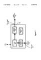
- FIG. 1is a functional block diagram of a monitor power controlling system in accordance with the present invention.
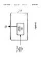
- FIG. 2is a functional block diagram of the keyboard controller illustrated in FIG. 1, in accordance with the present invention.
- FIGS. 3A-3Care a functional block diagrams of different embodiments of the power control unit illustrated in FIG. 1, in accordance with the present invention.
- FIG. 4is a flow diagram of power controlling system operation, in accordance with the present invention.
- keyboard controller 130processes data interchange between keyboard 140 and CPU 110.
- keyboard controller 130may also be configured to process data from additional input devices, such as a mouse.
- keyboard controller 130also performs a check, described more fully below, to determine the duration of any periods of input inactivity. During lengthy periods of inactivity, it is desirable to turn off monitor 120, which typically displays data under the direction of CPU 110. Therefore, if inactivity persists beyond a threshold duration, keyboard controller 130 directs power control unit 150 to disconnect monitor 120 from power mains 160.
- keyboard controller 130may be implemented either as an application-specific integrated circuit, or by using a conventional keyboard controller processor programmed to perform the functions illustrated in FIG. 2.
- a conventional keyboard controller processor model 80C42 from INTELis used to implement keyboard controller 130, but those skilled in the art will recognize that many of the popular keyboard controller processors, such as the model 80C42 from NEC, may alternatively be used to implement keyboard controller 130. Further information regarding such processors may be found in each processor's published technical documentation, for instance the INTEL UPI-C42 Data Sheet.
- keyboard controller 130is comprised of three pertinent components: input detector 210, timer 220 and port pin assertor 230.
- input detector 210detects input from keyboard 140 and possibly another input device such as a mouse (not shown).
- Timer 220computes the elapsed time between occurrences of input activity as detected by input detector 210. If the duration between input activity occurrences exceeds a threshold value, timer 220 directs port pin assertor 230 to assert a signal on an output pin of keyboard controller 130, which is coupled to power control unit 150.
- a fourth component, memory 240is illustrated in FIG. 2 to indicate that the processor instructions directing the operation of input detector 210, timer 220, and port pin assertor 230 are stored in memory 240 associated with keyboard controller 130.
- memory 240is implemented using the conventional internal read-only memory (ROM) of the 80C42 processor storing the general purpose program instructions of the 80C42 processor, along with internal random access memory (RAM) locations storing configuration information such as the identification of the pin to be toggled, desired time-out values, instructions to toggle the pin upon occurrence of a time-out condition, and calibration values to compensate the internal timers of the 80C42 processor for variations in the clock frequency at which the processor is running.
- ROMread-only memory
- RAMinternal random access memory
- input detector 210is implemented by periodically polling the conventional "keyboard clock” line from keyboard 140, which, in a preferred embodiment is typically applied to the "T0" input, or pin number 1, of the 80C42 processor used to implement keyboard controller 130. In some embodiments, input detector 210 also polls the conventional "auxiliary clock” line, applied to the "T1" input, or pin 39, of the 80C42 processor, to detect activity on an auxiliary input device such as a mouse. An assembly-code software routine stored in memory 240 directs the keyboard controller 130 to poll the T1 input, as described in the pseudocode representation below:
- timer 220is implemented by the conventional timer/counter hardware of the 80C42 processor, in conjunction with the conventional program instructions stored in the 80C42 internal ROM and configuration values stored in RAM as discussed above.
- the software routine that directs the keyboard controller 130 to measure a time between successive input activity as detected b,y input detector 210is described in the pseudocode representation below:
- port pin assertor 230is also implemented by a combination of the conventional hardware and program instructions of the 80C42 processor and additional program instructions that direct the keyboard controller 130 to assert a signal on the P13 output, or pin number 30, of the 80C42 processor if timer 220 indicates a duration of inactivity exceeding a predetermined threshold, as described in the pseudocode representation below:
- keyboard controller 130continues to sample for activity.
- port pin assertoris directed to reset the signal on the output pin P13 of keyboard controller 130, and the process of inactivity timing described above begins again.
- the pseudocode representation of this processis as follows:
- the configuration information described aboveis loaded into the previously described RAM portion of memory 240 by CPU 110, under control of a conventional basic input-output system program, at system start-up.
- CPU 110may provide the user of computer system 50 with an opportunity to alter this configuration information by selecting certain parameters of operation through configuration files or interactive queries on start-up.
- the threshold duration of keyboard inactivitymay be varied by the user, or the power controlling system 100 may be disabled in certain circumstances, for instance when the computer is being used to display information without the need for user input.
- a pseudocode representation of one possible controller initialization processis as follows:
- FIG. 3Athere is shown a functional block diagram of power control unit 150.
- a voltage-controlled switch 310is inserted between power mains 160 and monitor 120.
- the P13 output signal from keyboard controller 130is applied as an input control signal to voltage-controlled switch 310.
- voltage-controlled switch 310opens and interrupts power to monitor 120.
- voltage-controlled switch 310is implemented using a model 0AC-5 solid-state relay from CRYDOM.
- power control unit 150simply interrupts power from power mains 160 to monitor 120. This simple function facilitates retrofitting to virtually any external video monitor. There is no need for any physical change to the overall computer system 50, other than addition of power control unit 150 and a connection between pin 30 of controller 130 and power control unit 150.
- power control unit 150 and monitor 120could be readily configured to place monitor 120 in a low-power stand-by mode in which most of the circuitry of monitor 120 is deactivated, with the conventional cathode ray tube heater (not shown) activated at a reduced power level. In such a manner, the monitor 120 when reactivated requires very little warm-up time before it is ready for operation.
- the power control unit 150 of FIG. 3Bincludes stand-by mode logic circuitry 315 to generate signals to bring monitor 120 into and out of such stand-by mode in response to the "P13" output from keyboard controller 130.
- the power control unitmay be coupled to video controller circuitry (such as a conventional VGA controller card) to provide a signal that will cause the monitor to enter a standby mode under the existing protocols of the video controller circuitry.
- video controller circuitrysuch as a conventional VGA controller card
- VESAVGA computer video standard committee
- the stand-by mode logic circuitry 315 of FIG. 3Bwould be coupled to video controller circuitry resident either in monitor 120 or, more conventionally, in CPU 110.
- power control unit 150may include interrupt generation logic 318 that is coupled to interrupt circuitry of CPU 110 to cause a system interrupt to occur once prolonged keyboard inactivity is detected, as indicated by the "P13" output from keyboard controller 130.
- a system management interrupt (SMI) signalmay be generated to cause CPU 110 to issue any of a variety of desired commands. For example, if monitor 120 uses more power when displaying white pixels thorn when displaying black pixels, CPU 110 might simply send all black pixels to, monitor 120. In another yet possible embodiment, CPU 110 might disable the generation of synchronization signals to the monitor if this will result in a power-saving mode.
- SMIsystem management interrupt
- CPU 110might, upon this SMI signal, issue conventional commands directing that other peripheral devices such as disk drives switch off or to a low power mode. Even though use of SMI signals in this embodiment does require some use of CPU 110, that use of CPU 110 does not include the task of continuing to check for input activity.
- step 401the keyboard controller 130 initiating polling of the keyboard 140 and possibly other input devices for activity.
- step 402routes operation to step 405 if there is keyboard or other input device activity, and to step 403 if no activity is detected.
- step 403a check is made to see whether a predetermined threshold time has been exceeded.
- the threshold timeis typically set at 20 minutes, but the threshold may easily be reconfigured for other values as described above. If no activity is detected, operation returns to step 402 for subsequent checking of keyboard or other input device activity.
- step 403If the threshold time has been exceeded, then operation moves from step 403 to step 404, at which point the monitor 120 is turned off, and operation returns to step 401. If keyboard or other input device activity is detected in step 402, operation moves to step 405, where the keyboard controller 130 obtains the data from the keyboard 140 or other input device, turns on monitor 120 if it is not already on, and resets operation to step 401.
- the power control function of the present inventionneed not be applied only to video monitors. Another possible application is to control power to laser printers, the heaters for which typically require significant power. Those skilled in the art will recognize application of the present invention to other peripheral devices such as scanners, facsimile devices, modems, and the like.
Landscapes
- Engineering & Computer Science (AREA)
- Theoretical Computer Science (AREA)
- Physics & Mathematics (AREA)
- General Engineering & Computer Science (AREA)
- General Physics & Mathematics (AREA)
- Power Sources (AREA)
Abstract
Description
______________________________________ Main: if command received call process command; else if data for keyboard received call send.sub.-- keydata; else if output buffer empty & keyboard enabled enable clock line; if keyboard start call process key else if port pin true continue else call inactivity.sub.-- timer; else jmp main; ______________________________________
______________________________________ Inactivity.sub.-- Timer: if timercounter overflowed increment timer register; if timer register overflows call set.sub.-- portpin; return; else return; else return; ______________________________________
______________________________________ Set.sub.-- portpin: set port pin true; return; ______________________________________
______________________________________ Process.sub.-- key: disable mouse; call get.sub.-- scancode; disable keyboard; call reset.sub.-- portpin; output scancode to system; reset timer register; reset timer/counter hardware; return; Reset.sub.-- portpin: output port pin false; return; Get.sub.-- scancode: read serial scan code; return; ______________________________________
______________________________________ Init.sub.-- 8042timer: output timer command to 8042; output timer value to 8042; output pin definition data to 8042; return; ______________________________________
Claims (9)
Priority Applications (1)
| Application Number | Priority Date | Filing Date | Title |
|---|---|---|---|
| US08/384,350US5630144A (en) | 1993-02-19 | 1995-02-02 | Desktop computer monitor power control using keyboard controller |
Applications Claiming Priority (2)
| Application Number | Priority Date | Filing Date | Title |
|---|---|---|---|
| US2029293A | 1993-02-19 | 1993-02-19 | |
| US08/384,350US5630144A (en) | 1993-02-19 | 1995-02-02 | Desktop computer monitor power control using keyboard controller |
Related Parent Applications (1)
| Application Number | Title | Priority Date | Filing Date |
|---|---|---|---|
| US2029293AContinuation | 1993-02-19 | 1993-02-19 |
Publications (1)
| Publication Number | Publication Date |
|---|---|
| US5630144Atrue US5630144A (en) | 1997-05-13 |
Family
ID=21797789
Family Applications (1)
| Application Number | Title | Priority Date | Filing Date |
|---|---|---|---|
| US08/384,350Expired - LifetimeUS5630144A (en) | 1993-02-19 | 1995-02-02 | Desktop computer monitor power control using keyboard controller |
Country Status (1)
| Country | Link |
|---|---|
| US (1) | US5630144A (en) |
Cited By (26)
| Publication number | Priority date | Publication date | Assignee | Title |
|---|---|---|---|---|
| US5786903A (en)* | 1996-04-23 | 1998-07-28 | Must Systems Inc. | Multi-power control system for scanners |
| US5822598A (en)* | 1996-07-12 | 1998-10-13 | Ast Research, Inc. | Audio activity detection circuit to increase battery life in portable computers |
| US5838983A (en)* | 1996-08-20 | 1998-11-17 | Compaq Computer Corporation | Portable computer with low power audio CD-player |
| US5919263A (en)* | 1992-09-04 | 1999-07-06 | Elougx I.P. Holdings L.T.D. | Computer peripherals low-power-consumption standby system |
| US5922075A (en)* | 1996-12-20 | 1999-07-13 | Intel Corporation | Power management control of pointing devices during low-power states |
| US5925110A (en)* | 1997-01-07 | 1999-07-20 | Micron Electronics, Inc. | Low power keyboard with power supply switch that is activated by receiver output to power up and down keyboard components including microcontroller demodulator |
| US6038672A (en)* | 1998-01-13 | 2000-03-14 | Micron Electronics, Inc. | Portable computer with low power CD-player mode |
| US6085329A (en)* | 1998-01-13 | 2000-07-04 | Micron Electronics, Inc. | Portable computer with low power CD-player mode |
| US6266714B1 (en) | 1997-04-30 | 2001-07-24 | Compaq Computer Corporation | Audio CD play subsystem capable for playing audio CDs in a CD-ROM drive during computer system is in power-off state |
| US6385734B2 (en) | 1996-06-03 | 2002-05-07 | Compaq Information Technologies Group, L.P. | Portable computer with low power audio CD-player |
| US20020129288A1 (en)* | 2001-03-08 | 2002-09-12 | Loh Weng Wah | Computing device having a low power secondary processor coupled to a keyboard controller |
| US6502003B1 (en) | 1997-06-20 | 2002-12-31 | Compaq Information Technologies Group, L.P. | Method and system for controlling a CD-ROM drive in an operating system-independent reduced power mode |
| US20030092493A1 (en)* | 2001-11-13 | 2003-05-15 | Takao Shimizu | Game system with enhanced low power mode-related processing |
| WO2003071408A1 (en)* | 2002-02-19 | 2003-08-28 | Peter Kouropoulos | Personal computer failsafe protection device |
| US20030163746A1 (en)* | 2002-02-22 | 2003-08-28 | Yi-Chung Lee | Power-saving method for an optical disc drive |
| EP1191427A3 (en)* | 2000-09-22 | 2003-12-17 | Kabushiki Kaisha Toshiba | Information processing apparatus and display light control method |
| US20040163003A1 (en)* | 2003-02-13 | 2004-08-19 | Dutton Drew J. | Power management of computer peripheral devices which determines non-usage of a device through usage detection of other devices |
| US6792480B2 (en) | 1997-04-30 | 2004-09-14 | Hewlett-Packard Development Company, L.P. | Status display being visible in a closed position and displaying a track number during play mode comprising a reduced power of a system |
| US6801196B1 (en)* | 1999-11-18 | 2004-10-05 | Intel Corporation | Method and apparatus to control power state of a display device |
| US20050152111A1 (en)* | 2004-01-12 | 2005-07-14 | Skurdal Vincent C. | Docking station for a wireless mouse with control of a computer |
| US7243249B1 (en)* | 2000-09-29 | 2007-07-10 | Intel Corporation | Method and apparatus for facilitating power state control and awareness of an autonomous subsystem in a computer based system |
| US7243243B2 (en)* | 2002-08-29 | 2007-07-10 | Intel Corporatio | Apparatus and method for measuring and controlling power consumption of a computer system |
| US20070287376A1 (en)* | 2006-06-13 | 2007-12-13 | Microsoft Corporation | Techniques for setting and indicating presence for a device |
| US20080215898A1 (en)* | 2006-12-22 | 2008-09-04 | Innocom Technology (Shenzhen) Co., Ltd. | Computer device having display device capable of being automatically turned off or turned on according to switch motion of host |
| US20080222433A1 (en)* | 2005-08-31 | 2008-09-11 | Won Sik Kim | Method and Apparatus for Supplying Power, and Display Device |
| US20150046104A1 (en)* | 2011-06-30 | 2015-02-12 | Mark M. Chang | Techniques for utilizing energy usage information |
Citations (23)
| Publication number | Priority date | Publication date | Assignee | Title |
|---|---|---|---|---|
| US4285043A (en)* | 1976-09-21 | 1981-08-18 | Sharp Kabushiki Kaisha | Power transmission controller for electronic calculators |
| US4317181A (en)* | 1979-12-26 | 1982-02-23 | Texas Instruments Incorporated | Four mode microcomputer power save operation |
| US4365290A (en)* | 1979-03-12 | 1982-12-21 | Medtronic, Inc. | Computer system with power control circuit |
| US4649373A (en)* | 1983-08-10 | 1987-03-10 | International Business Machines Corporation | Powered conservation system in battery powered keyboard device including a microprocessor |
| US4698748A (en)* | 1983-10-07 | 1987-10-06 | Essex Group, Inc. | Power-conserving control system for turning-off the power and the clocking for data transactions upon certain system inactivity |
| US4841440A (en)* | 1983-04-26 | 1989-06-20 | Nec Corporation | Control processor for controlling a peripheral unit |
| US4851987A (en)* | 1986-01-17 | 1989-07-25 | International Business Machines Corporation | System for reducing processor power consumption by stopping processor clock supply if a desired event does not occur |
| US5041964A (en)* | 1989-06-12 | 1991-08-20 | Grid Systems Corporation | Low-power, standby mode computer |
| US5083266A (en)* | 1986-12-26 | 1992-01-21 | Kabushiki Kaisha Toshiba | Microcomputer which enters sleep mode for a predetermined period of time on response to an activity of an input/output device |
| EP0488384A1 (en)* | 1990-11-30 | 1992-06-03 | Gold Star Co. Ltd | Electric power saving device of a portable data terminal and its method |
| US5167024A (en)* | 1989-09-08 | 1992-11-24 | Apple Computer, Inc. | Power management for a laptop computer with slow and sleep modes |
| JPH04355811A (en)* | 1991-06-04 | 1992-12-09 | Nec Corp | Input/output interface control circuit |
| WO1993007558A1 (en)* | 1991-10-04 | 1993-04-15 | National Research Council Of Canada | Power management system |
| DE4234150A1 (en)* | 1991-10-11 | 1993-04-15 | Toshiba Kawasaki Kk | Energy consumption reduction system for computer - puts computer into standby mode by executing interrupt routine when absence of data entry is detected within set period |
| US5214785A (en)* | 1989-09-27 | 1993-05-25 | Third Point Systems, Inc. | Controller with keyboard emulation capability for control of host computer operation |
| EP0545828A2 (en)* | 1991-12-04 | 1993-06-09 | Fujitsu Limited | Power source control apparatus for display unit |
| US5237692A (en)* | 1990-11-09 | 1993-08-17 | Ast Research Inc. | Internal interrupt controller for a peripheral controller |
| US5249298A (en)* | 1988-12-09 | 1993-09-28 | Dallas Semiconductor Corporation | Battery-initiated touch-sensitive power-up |
| US5283906A (en)* | 1992-03-16 | 1994-02-01 | Silitek Corporation | Notebook computer CMOS firmware processing method and the related hardware |
| US5347167A (en)* | 1990-08-09 | 1994-09-13 | Sophisticated Circuits, Inc. | Power controller using keyboard and computer interface |
| US5355503A (en)* | 1990-05-31 | 1994-10-11 | National Semiconductor Corporation | Event driven scanning of data input equipment using multi-input wake-up techniques |
| US5390350A (en)* | 1991-04-22 | 1995-02-14 | Western Digital Corporation | Integrated circuit chip core logic system controller with power saving features for a microcomputer system |
| US5454112A (en)* | 1990-02-09 | 1995-09-26 | Kabushiki Kaisha Toshiba | Personal computer or the like with a light source controller for a display apparatus |
- 1995
- 1995-02-02USUS08/384,350patent/US5630144A/ennot_activeExpired - Lifetime
Patent Citations (24)
| Publication number | Priority date | Publication date | Assignee | Title |
|---|---|---|---|---|
| US4285043A (en)* | 1976-09-21 | 1981-08-18 | Sharp Kabushiki Kaisha | Power transmission controller for electronic calculators |
| US4365290A (en)* | 1979-03-12 | 1982-12-21 | Medtronic, Inc. | Computer system with power control circuit |
| US4317181A (en)* | 1979-12-26 | 1982-02-23 | Texas Instruments Incorporated | Four mode microcomputer power save operation |
| US4841440A (en)* | 1983-04-26 | 1989-06-20 | Nec Corporation | Control processor for controlling a peripheral unit |
| US4649373A (en)* | 1983-08-10 | 1987-03-10 | International Business Machines Corporation | Powered conservation system in battery powered keyboard device including a microprocessor |
| US4698748A (en)* | 1983-10-07 | 1987-10-06 | Essex Group, Inc. | Power-conserving control system for turning-off the power and the clocking for data transactions upon certain system inactivity |
| US4851987A (en)* | 1986-01-17 | 1989-07-25 | International Business Machines Corporation | System for reducing processor power consumption by stopping processor clock supply if a desired event does not occur |
| US5083266A (en)* | 1986-12-26 | 1992-01-21 | Kabushiki Kaisha Toshiba | Microcomputer which enters sleep mode for a predetermined period of time on response to an activity of an input/output device |
| US5249298A (en)* | 1988-12-09 | 1993-09-28 | Dallas Semiconductor Corporation | Battery-initiated touch-sensitive power-up |
| US5041964A (en)* | 1989-06-12 | 1991-08-20 | Grid Systems Corporation | Low-power, standby mode computer |
| US5167024A (en)* | 1989-09-08 | 1992-11-24 | Apple Computer, Inc. | Power management for a laptop computer with slow and sleep modes |
| US5214785A (en)* | 1989-09-27 | 1993-05-25 | Third Point Systems, Inc. | Controller with keyboard emulation capability for control of host computer operation |
| US5454112A (en)* | 1990-02-09 | 1995-09-26 | Kabushiki Kaisha Toshiba | Personal computer or the like with a light source controller for a display apparatus |
| US5355503A (en)* | 1990-05-31 | 1994-10-11 | National Semiconductor Corporation | Event driven scanning of data input equipment using multi-input wake-up techniques |
| US5347167A (en)* | 1990-08-09 | 1994-09-13 | Sophisticated Circuits, Inc. | Power controller using keyboard and computer interface |
| US5237692A (en)* | 1990-11-09 | 1993-08-17 | Ast Research Inc. | Internal interrupt controller for a peripheral controller |
| EP0488384A1 (en)* | 1990-11-30 | 1992-06-03 | Gold Star Co. Ltd | Electric power saving device of a portable data terminal and its method |
| US5390350A (en)* | 1991-04-22 | 1995-02-14 | Western Digital Corporation | Integrated circuit chip core logic system controller with power saving features for a microcomputer system |
| JPH04355811A (en)* | 1991-06-04 | 1992-12-09 | Nec Corp | Input/output interface control circuit |
| WO1993007558A1 (en)* | 1991-10-04 | 1993-04-15 | National Research Council Of Canada | Power management system |
| US5371693A (en)* | 1991-10-11 | 1994-12-06 | Kabushiki Kaisha Toshiba | Computer with power saving function |
| DE4234150A1 (en)* | 1991-10-11 | 1993-04-15 | Toshiba Kawasaki Kk | Energy consumption reduction system for computer - puts computer into standby mode by executing interrupt routine when absence of data entry is detected within set period |
| EP0545828A2 (en)* | 1991-12-04 | 1993-06-09 | Fujitsu Limited | Power source control apparatus for display unit |
| US5283906A (en)* | 1992-03-16 | 1994-02-01 | Silitek Corporation | Notebook computer CMOS firmware processing method and the related hardware |
Non-Patent Citations (12)
| Title |
|---|
| APPIAN, "P94 PowerMizer™ Power Manager Controller, Advanced Product Description," The New Vision In Systems Solutions, Nov. 1990 pp. 1 though 4 and 6. |
| APPIAN, P94 PowerMizer Power Manager Controller, Advanced Product Description, The New Vision In Systems Solutions, Nov. 1990 pp. 1 though 4 and 6.* |
| Intel386 SL Microprcessor SuperSet System Design Guide, Chapter 14, System and Power Management, 1992, pp. 14 1 through 14 7.* |
| Intel386™ SL Microprcessor SuperSet System Design Guide, Chapter 14, "System and Power Management," 1992, pp. 14-1 through 14-7. |
| Interarc III Platform Designer s Guide, Western Digital, WD7600LP Chip Set, Interarc III Functionality, Advance Information, Dec. 12, 1990, pp. 8 through 11.* |
| Interarc III Platform Designer's Guide, Western Digital, "WD7600LP Chip Set, Interarc III Functionality," Advance Information, Dec. 12, 1990, pp. 8 through 11. |
| Motorola Semiconductor Technical Data, "8-Bit Microcomputer, LAPKAT MC 68HC05G8," Product Preview (Rev. 1.0), Motorola Inc., 1990, pp. Intro 1-3, APX B-1, A7-1 to A7-3. |
| Motorola Semiconductor Technical Data, 8 Bit Microcomputer, LAPKAT MC 68HC05G8, Product Preview (Rev. 1.0), Motorola Inc., 1990, pp. Intro 1 3, APX B 1, A7 1 to A7 3.* |
| PicoPower Technology, Inc., "The PicoPower `Evergreen,` 486/386DX Portable Computer Core Chip," Preliminary Data Book, Version 1.3.1, Sep. 16, 1992, pp. i through 65. |
| PicoPower Technology, Inc., The PicoPower Evergreen, 486/386DX Portable Computer Core Chip, Preliminary Data Book, Version 1.3.1, Sep. 16, 1992, pp. i through 65.* |
| VLSI Technology, Inc., "Advance Information, VL82C322A,"pp. 1-2, 4-15, 21-23, 27-29. |
| VLSI Technology, Inc., Advance Information, VL82C322A, pp. 1 2, 4 15, 21 23, 27 29.* |
Cited By (42)
| Publication number | Priority date | Publication date | Assignee | Title |
|---|---|---|---|---|
| US5919263A (en)* | 1992-09-04 | 1999-07-06 | Elougx I.P. Holdings L.T.D. | Computer peripherals low-power-consumption standby system |
| US5786903A (en)* | 1996-04-23 | 1998-07-28 | Must Systems Inc. | Multi-power control system for scanners |
| US6088809A (en)* | 1996-06-03 | 2000-07-11 | Compaq Computer Corporation | Portable computer with low-power audio cd-player |
| US6385734B2 (en) | 1996-06-03 | 2002-05-07 | Compaq Information Technologies Group, L.P. | Portable computer with low power audio CD-player |
| US6378077B1 (en) | 1996-06-03 | 2002-04-23 | Compaq Information Technologies Group, L.P. | Portable computer with low-power audio CD-player |
| US5822598A (en)* | 1996-07-12 | 1998-10-13 | Ast Research, Inc. | Audio activity detection circuit to increase battery life in portable computers |
| US5838983A (en)* | 1996-08-20 | 1998-11-17 | Compaq Computer Corporation | Portable computer with low power audio CD-player |
| US5922075A (en)* | 1996-12-20 | 1999-07-13 | Intel Corporation | Power management control of pointing devices during low-power states |
| US5925110A (en)* | 1997-01-07 | 1999-07-20 | Micron Electronics, Inc. | Low power keyboard with power supply switch that is activated by receiver output to power up and down keyboard components including microcontroller demodulator |
| US5958023A (en)* | 1997-01-07 | 1999-09-28 | Micron Electronics, Inc. | Method for low power wireless keyboard that detects a host computer query for the state of a key then powers up to determine and transmit back the state of that key |
| US6266714B1 (en) | 1997-04-30 | 2001-07-24 | Compaq Computer Corporation | Audio CD play subsystem capable for playing audio CDs in a CD-ROM drive during computer system is in power-off state |
| US6279056B1 (en) | 1997-04-30 | 2001-08-21 | Compaq Computer Corporation | Computer system capable of playing audio CDs in a CD-ROM drive independent of an operating system |
| US6792480B2 (en) | 1997-04-30 | 2004-09-14 | Hewlett-Packard Development Company, L.P. | Status display being visible in a closed position and displaying a track number during play mode comprising a reduced power of a system |
| US6704811B2 (en) | 1997-04-30 | 2004-03-09 | Hewlett-Packard Development Company, L.P. | Audio CD play controller for controlling a CD-rom drive independent of system bios of a computer system |
| US6819961B2 (en) | 1997-06-20 | 2004-11-16 | Hewlett-Packard Development Company, L.P. | Controls and indicators for a secondary operational mode of a computer system |
| US6502003B1 (en) | 1997-06-20 | 2002-12-31 | Compaq Information Technologies Group, L.P. | Method and system for controlling a CD-ROM drive in an operating system-independent reduced power mode |
| US6085329A (en)* | 1998-01-13 | 2000-07-04 | Micron Electronics, Inc. | Portable computer with low power CD-player mode |
| US6038672A (en)* | 1998-01-13 | 2000-03-14 | Micron Electronics, Inc. | Portable computer with low power CD-player mode |
| US6412075B1 (en) | 1998-01-13 | 2002-06-25 | Micron Technology, Inc. | Portable computer with low power CD-player mode |
| US6801196B1 (en)* | 1999-11-18 | 2004-10-05 | Intel Corporation | Method and apparatus to control power state of a display device |
| EP1191427A3 (en)* | 2000-09-22 | 2003-12-17 | Kabushiki Kaisha Toshiba | Information processing apparatus and display light control method |
| US7243249B1 (en)* | 2000-09-29 | 2007-07-10 | Intel Corporation | Method and apparatus for facilitating power state control and awareness of an autonomous subsystem in a computer based system |
| GB2375410A (en)* | 2001-03-08 | 2002-11-13 | Hewlett Packard Co | Computing device having a low power secondary processor coupled to a keyboard controller |
| US20020129288A1 (en)* | 2001-03-08 | 2002-09-12 | Loh Weng Wah | Computing device having a low power secondary processor coupled to a keyboard controller |
| US20030092493A1 (en)* | 2001-11-13 | 2003-05-15 | Takao Shimizu | Game system with enhanced low power mode-related processing |
| US8506411B2 (en)* | 2001-11-13 | 2013-08-13 | Nintendo Co., Ltd. | Game system with enhanced low power mode-related processing |
| WO2003071408A1 (en)* | 2002-02-19 | 2003-08-28 | Peter Kouropoulos | Personal computer failsafe protection device |
| US20030163746A1 (en)* | 2002-02-22 | 2003-08-28 | Yi-Chung Lee | Power-saving method for an optical disc drive |
| US7243243B2 (en)* | 2002-08-29 | 2007-07-10 | Intel Corporatio | Apparatus and method for measuring and controlling power consumption of a computer system |
| US7685450B2 (en) | 2003-02-13 | 2010-03-23 | Standard Microsystems Corporation | Power management of computer peripheral devices which determines non-usage of a device through usage detection of other devices |
| US20040163003A1 (en)* | 2003-02-13 | 2004-08-19 | Dutton Drew J. | Power management of computer peripheral devices which determines non-usage of a device through usage detection of other devices |
| US7222252B2 (en)* | 2003-02-13 | 2007-05-22 | Standard Microsystems Corporation | Power management of computer peripheral devices which determines non-usage of a device through usage detection of other devices |
| US20070162778A1 (en)* | 2003-02-13 | 2007-07-12 | Dutton Drew J | Power Management of Computer Peripheral Devices Which Determines Non-Usage of a Device Through Usage Detection of Other Devices |
| US20050152111A1 (en)* | 2004-01-12 | 2005-07-14 | Skurdal Vincent C. | Docking station for a wireless mouse with control of a computer |
| US7200765B2 (en)* | 2004-01-12 | 2007-04-03 | Hewlett-Packard Development Company, L.P. | Docking station for a wireless mouse with control of a computer |
| US20080222433A1 (en)* | 2005-08-31 | 2008-09-11 | Won Sik Kim | Method and Apparatus for Supplying Power, and Display Device |
| US7971085B2 (en)* | 2005-08-31 | 2011-06-28 | Lg Electronics Inc. | Method and apparatus for supplying power, and display device |
| US20070287376A1 (en)* | 2006-06-13 | 2007-12-13 | Microsoft Corporation | Techniques for setting and indicating presence for a device |
| US7907051B2 (en)* | 2006-06-13 | 2011-03-15 | Microsoft Corporation | Techniques for setting and indicating presence for a device |
| US20080215898A1 (en)* | 2006-12-22 | 2008-09-04 | Innocom Technology (Shenzhen) Co., Ltd. | Computer device having display device capable of being automatically turned off or turned on according to switch motion of host |
| US7917782B2 (en)* | 2006-12-22 | 2011-03-29 | Innocom Technology (Shenzhen) Co., Ltd. | Computer device having display device capable of being automatically turned off or turned on according to switch motion of host |
| US20150046104A1 (en)* | 2011-06-30 | 2015-02-12 | Mark M. Chang | Techniques for utilizing energy usage information |
Similar Documents
| Publication | Publication Date | Title |
|---|---|---|
| US5630144A (en) | Desktop computer monitor power control using keyboard controller | |
| US7353413B2 (en) | Computer system power policy adjustment in response to an affirmative indication from a user | |
| US7219240B2 (en) | Monitor and method for controlling power-on and power-off of host computer | |
| US5167024A (en) | Power management for a laptop computer with slow and sleep modes | |
| US5355501A (en) | Idle detection system | |
| US6065122A (en) | Smart battery power management in a computer system | |
| US6105142A (en) | Intelligent power management interface for computer system hardware | |
| US5991883A (en) | Power conservation method for a portable computer with LCD display | |
| US6018232A (en) | Method of operating battery powered computing device with radio transmitter | |
| US6775784B1 (en) | Power supply control circuit and method for cutting off unnecessary power to system memory in the power-off state | |
| US5974551A (en) | Power supply device and a power supply method for a computer system | |
| US7152172B2 (en) | Method and apparatus for real time monitoring of user presence to prolong a portable computer battery operation time | |
| EP0666525B1 (en) | Method and apparatus for control of power consumption in a computer system | |
| US6121962A (en) | Computer system and method for controlling screen display of a monitor in a power management mode | |
| US5446906A (en) | Method and apparatus for suspending and resuming a keyboard controller | |
| US5926404A (en) | Computer system with unattended operation power-saving suspend mode | |
| US6065124A (en) | Computer system having power saving and management function and method of controlling the same | |
| US5504908A (en) | Power saving control system for computer system | |
| US7411631B1 (en) | Power management for processor-based appliances | |
| US6193422B1 (en) | Implementation of idle mode in a suspend/resume microprocessor system | |
| EP0662652A3 (en) | Method and apparatus for reducing power consumption in a computer system | |
| US6269449B1 (en) | Capacitive wake-up mechanism for hand held data entry unit | |
| US20020104030A1 (en) | ACPI compliant computer system and overtemperature protection method therefor | |
| EP0855718A1 (en) | Memory low power mode control | |
| US6272645B1 (en) | Method and control circuit for waking up a computer system from standby mode |
Legal Events
| Date | Code | Title | Description |
|---|---|---|---|
| STCF | Information on status: patent grant | Free format text:PATENTED CASE | |
| FEPP | Fee payment procedure | Free format text:PAT HLDR NO LONGER CLAIMS SMALL ENT STAT AS INDIV INVENTOR (ORIGINAL EVENT CODE: LSM1); ENTITY STATUS OF PATENT OWNER: LARGE ENTITY | |
| FEPP | Fee payment procedure | Free format text:PAYOR NUMBER ASSIGNED (ORIGINAL EVENT CODE: ASPN); ENTITY STATUS OF PATENT OWNER: LARGE ENTITY | |
| FPAY | Fee payment | Year of fee payment:4 | |
| FEPP | Fee payment procedure | Free format text:PAT HOLDER CLAIMS SMALL ENTITY STATUS, ENTITY STATUS SET TO SMALL (ORIGINAL EVENT CODE: LTOS); ENTITY STATUS OF PATENT OWNER: LARGE ENTITY | |
| FPAY | Fee payment | Year of fee payment:8 | |
| REMI | Maintenance fee reminder mailed | ||
| FEPP | Fee payment procedure | Free format text:PAT HOLDER NO LONGER CLAIMS SMALL ENTITY STATUS, ENTITY STATUS SET TO UNDISCOUNTED (ORIGINAL EVENT CODE: STOL); ENTITY STATUS OF PATENT OWNER: LARGE ENTITY | |
| FPAY | Fee payment | Year of fee payment:12 | |
| SULP | Surcharge for late payment | Year of fee payment:11 | |
| AS | Assignment | Owner name:HIGHBRIDGE PRINCIPAL STRATEGIES, LLC, AS COLLATERA Free format text:GRANT OF SECURITY INTEREST - PATENTS;ASSIGNOR:PHOENIX TECHNOLOGIES LTD.;REEL/FRAME:025406/0604 Effective date:20101123 | |
| AS | Assignment | Owner name:MEP PLP, LLC, CALIFORNIA Free format text:SECURITY AGREEMENT;ASSIGNOR:HIGHBRIDGE PRINCIPAL STRATEGIES, LLC;REEL/FRAME:029291/0354 Effective date:20121109 | |
| AS | Assignment | Owner name:PHOENIX TECHNOLOGIES LTD., CALIFORNIA Free format text:RELEASE BY SECURED PARTY;ASSIGNOR:MEP PLP, LLC;REEL/FRAME:029307/0590 Effective date:20121112 | |
| AS | Assignment | Owner name:KINGLITE HOLDINGS INC., SINGAPORE Free format text:ASSIGNMENT OF ASSIGNORS INTEREST;ASSIGNOR:PHOENIX TECHNOLOGIES LTD.;REEL/FRAME:029339/0716 Effective date:20121115 | |
| AS | Assignment | Owner name:AMERICAN MEGATRENDS, INC., GEORGIA Free format text:LIEN AND SECURITY INTEREST;ASSIGNOR:KINGLITE HOLDINGS INC.;REEL/FRAME:041366/0255 Effective date:20161121 |