US5629871A - Wear trend analysis technique for components of a dialysis machine - Google Patents
Wear trend analysis technique for components of a dialysis machineDownload PDFInfo
- Publication number
- US5629871A US5629871AUS08/486,942US48694295AUS5629871AUS 5629871 AUS5629871 AUS 5629871AUS 48694295 AUS48694295 AUS 48694295AUS 5629871 AUS5629871 AUS 5629871A
- Authority
- US
- United States
- Prior art keywords
- value
- pump
- component
- dialysis machine
- actual
- Prior art date
- Legal status (The legal status is an assumption and is not a legal conclusion. Google has not performed a legal analysis and makes no representation as to the accuracy of the status listed.)
- Expired - Lifetime
Links
- 238000000502dialysisMethods0.000titleclaimsabstractdescription102
- 238000000034methodMethods0.000titleclaimsdescription33
- 238000012360testing methodMethods0.000claimsabstractdescription94
- 238000012423maintenanceMethods0.000claimsabstractdescription87
- 230000002159abnormal effectEffects0.000claimsabstractdescription27
- 238000000108ultra-filtrationMethods0.000claimsdescription38
- 238000011282treatmentMethods0.000claimsdescription32
- 238000012544monitoring processMethods0.000claimsdescription8
- 230000002572peristaltic effectEffects0.000claimsdescription8
- 238000004364calculation methodMethods0.000claimsdescription6
- 230000002123temporal effectEffects0.000claims4
- 239000008280bloodSubstances0.000description47
- 210000004369bloodAnatomy0.000description47
- 230000009471actionEffects0.000description15
- 238000007872degassingMethods0.000description15
- 239000000126substanceSubstances0.000description13
- 239000002699waste materialSubstances0.000description12
- 230000007257malfunctionEffects0.000description9
- 239000012530fluidSubstances0.000description7
- 230000000249desinfective effectEffects0.000description5
- 230000006870functionEffects0.000description5
- 230000001681protective effectEffects0.000description5
- 230000017531blood circulationEffects0.000description4
- 238000012546transferMethods0.000description4
- 239000003146anticoagulant agentSubstances0.000description3
- 229940127219anticoagulant drugDrugs0.000description3
- 244000005700microbiomeSpecies0.000description3
- 238000004659sterilization and disinfectionMethods0.000description3
- XLYOFNOQVPJJNP-UHFFFAOYSA-NwaterChemical compoundOXLYOFNOQVPJJNP-UHFFFAOYSA-N0.000description3
- BVKZGUZCCUSVTD-UHFFFAOYSA-MBicarbonateChemical compoundOC([O-])=OBVKZGUZCCUSVTD-UHFFFAOYSA-M0.000description2
- HTTJABKRGRZYRN-UHFFFAOYSA-NHeparinChemical compoundOC1C(NC(=O)C)C(O)OC(COS(O)(=O)=O)C1OC1C(OS(O)(=O)=O)C(O)C(OC2C(C(OS(O)(=O)=O)C(OC3C(C(O)C(O)C(O3)C(O)=O)OS(O)(=O)=O)C(CO)O2)NS(O)(=O)=O)C(C(O)=O)O1HTTJABKRGRZYRN-UHFFFAOYSA-N0.000description2
- 239000002253acidSubstances0.000description2
- 230000036760body temperatureEffects0.000description2
- 230000003247decreasing effectEffects0.000description2
- 238000010586diagramMethods0.000description2
- 230000000694effectsEffects0.000description2
- 229960002897heparinDrugs0.000description2
- 229920000669heparinPolymers0.000description2
- 230000007246mechanismEffects0.000description2
- 230000003287optical effectEffects0.000description2
- 238000009825accumulationMethods0.000description1
- 230000003466anti-cipated effectEffects0.000description1
- 230000009286beneficial effectEffects0.000description1
- 230000008859changeEffects0.000description1
- 238000004140cleaningMethods0.000description1
- 230000006378damageEffects0.000description1
- 230000007423decreaseEffects0.000description1
- 230000001934delayEffects0.000description1
- 230000001419dependent effectEffects0.000description1
- 239000000645desinfectantSubstances0.000description1
- 238000001514detection methodMethods0.000description1
- 230000009429distressEffects0.000description1
- 238000011156evaluationMethods0.000description1
- 238000013213extrapolationMethods0.000description1
- 230000003907kidney functionEffects0.000description1
- 239000000203mixtureSubstances0.000description1
- 238000002360preparation methodMethods0.000description1
- 230000003449preventive effectEffects0.000description1
- 239000008213purified waterSubstances0.000description1
Images


Classifications
- G—PHYSICS
- G07—CHECKING-DEVICES
- G07C—TIME OR ATTENDANCE REGISTERS; REGISTERING OR INDICATING THE WORKING OF MACHINES; GENERATING RANDOM NUMBERS; VOTING OR LOTTERY APPARATUS; ARRANGEMENTS, SYSTEMS OR APPARATUS FOR CHECKING NOT PROVIDED FOR ELSEWHERE
- G07C3/00—Registering or indicating the condition or the working of machines or other apparatus, other than vehicles
- A—HUMAN NECESSITIES
- A61—MEDICAL OR VETERINARY SCIENCE; HYGIENE
- A61M—DEVICES FOR INTRODUCING MEDIA INTO, OR ONTO, THE BODY; DEVICES FOR TRANSDUCING BODY MEDIA OR FOR TAKING MEDIA FROM THE BODY; DEVICES FOR PRODUCING OR ENDING SLEEP OR STUPOR
- A61M1/00—Suction or pumping devices for medical purposes; Devices for carrying-off, for treatment of, or for carrying-over, body-liquids; Drainage systems
- A61M1/14—Dialysis systems; Artificial kidneys; Blood oxygenators ; Reciprocating systems for treatment of body fluids, e.g. single needle systems for hemofiltration or pheresis
- A61M1/16—Dialysis systems; Artificial kidneys; Blood oxygenators ; Reciprocating systems for treatment of body fluids, e.g. single needle systems for hemofiltration or pheresis with membranes
- A61M1/1601—Control or regulation
- A—HUMAN NECESSITIES
- A61—MEDICAL OR VETERINARY SCIENCE; HYGIENE
- A61M—DEVICES FOR INTRODUCING MEDIA INTO, OR ONTO, THE BODY; DEVICES FOR TRANSDUCING BODY MEDIA OR FOR TAKING MEDIA FROM THE BODY; DEVICES FOR PRODUCING OR ENDING SLEEP OR STUPOR
- A61M1/00—Suction or pumping devices for medical purposes; Devices for carrying-off, for treatment of, or for carrying-over, body-liquids; Drainage systems
- A61M1/34—Filtering material out of the blood by passing it through a membrane, i.e. hemofiltration or diafiltration
- A61M1/3403—Regulation parameters
- A61M1/341—Regulation parameters by measuring the filtrate rate or volume
- A—HUMAN NECESSITIES
- A61—MEDICAL OR VETERINARY SCIENCE; HYGIENE
- A61M—DEVICES FOR INTRODUCING MEDIA INTO, OR ONTO, THE BODY; DEVICES FOR TRANSDUCING BODY MEDIA OR FOR TAKING MEDIA FROM THE BODY; DEVICES FOR PRODUCING OR ENDING SLEEP OR STUPOR
- A61M1/00—Suction or pumping devices for medical purposes; Devices for carrying-off, for treatment of, or for carrying-over, body-liquids; Drainage systems
- A61M1/36—Other treatment of blood in a by-pass of the natural circulatory system, e.g. temperature adaptation, irradiation ; Extra-corporeal blood circuits
- A61M1/3621—Extra-corporeal blood circuits
- A61M1/3622—Extra-corporeal blood circuits with a cassette forming partially or totally the blood circuit
- A61M1/36225—Extra-corporeal blood circuits with a cassette forming partially or totally the blood circuit with blood pumping means or components thereof
- A—HUMAN NECESSITIES
- A61—MEDICAL OR VETERINARY SCIENCE; HYGIENE
- A61M—DEVICES FOR INTRODUCING MEDIA INTO, OR ONTO, THE BODY; DEVICES FOR TRANSDUCING BODY MEDIA OR FOR TAKING MEDIA FROM THE BODY; DEVICES FOR PRODUCING OR ENDING SLEEP OR STUPOR
- A61M1/00—Suction or pumping devices for medical purposes; Devices for carrying-off, for treatment of, or for carrying-over, body-liquids; Drainage systems
- A61M1/36—Other treatment of blood in a by-pass of the natural circulatory system, e.g. temperature adaptation, irradiation ; Extra-corporeal blood circuits
- A61M1/3621—Extra-corporeal blood circuits
- A61M1/3622—Extra-corporeal blood circuits with a cassette forming partially or totally the blood circuit
- A61M1/36226—Constructional details of cassettes, e.g. specific details on material or shape
- A61M1/362262—Details of incorporated reservoirs
- A—HUMAN NECESSITIES
- A61—MEDICAL OR VETERINARY SCIENCE; HYGIENE
- A61M—DEVICES FOR INTRODUCING MEDIA INTO, OR ONTO, THE BODY; DEVICES FOR TRANSDUCING BODY MEDIA OR FOR TAKING MEDIA FROM THE BODY; DEVICES FOR PRODUCING OR ENDING SLEEP OR STUPOR
- A61M1/00—Suction or pumping devices for medical purposes; Devices for carrying-off, for treatment of, or for carrying-over, body-liquids; Drainage systems
- A61M1/36—Other treatment of blood in a by-pass of the natural circulatory system, e.g. temperature adaptation, irradiation ; Extra-corporeal blood circuits
- A61M1/3621—Extra-corporeal blood circuits
- A61M1/3622—Extra-corporeal blood circuits with a cassette forming partially or totally the blood circuit
- A61M1/36226—Constructional details of cassettes, e.g. specific details on material or shape
- A61M1/362266—Means for adding solutions or substances to the blood
- G—PHYSICS
- G16—INFORMATION AND COMMUNICATION TECHNOLOGY [ICT] SPECIALLY ADAPTED FOR SPECIFIC APPLICATION FIELDS
- G16H—HEALTHCARE INFORMATICS, i.e. INFORMATION AND COMMUNICATION TECHNOLOGY [ICT] SPECIALLY ADAPTED FOR THE HANDLING OR PROCESSING OF MEDICAL OR HEALTHCARE DATA
- G16H20/00—ICT specially adapted for therapies or health-improving plans, e.g. for handling prescriptions, for steering therapy or for monitoring patient compliance
- G16H20/40—ICT specially adapted for therapies or health-improving plans, e.g. for handling prescriptions, for steering therapy or for monitoring patient compliance relating to mechanical, radiation or invasive therapies, e.g. surgery, laser therapy, dialysis or acupuncture
- G—PHYSICS
- G16—INFORMATION AND COMMUNICATION TECHNOLOGY [ICT] SPECIALLY ADAPTED FOR SPECIFIC APPLICATION FIELDS
- G16H—HEALTHCARE INFORMATICS, i.e. INFORMATION AND COMMUNICATION TECHNOLOGY [ICT] SPECIALLY ADAPTED FOR THE HANDLING OR PROCESSING OF MEDICAL OR HEALTHCARE DATA
- G16H40/00—ICT specially adapted for the management or administration of healthcare resources or facilities; ICT specially adapted for the management or operation of medical equipment or devices
- G16H40/40—ICT specially adapted for the management or administration of healthcare resources or facilities; ICT specially adapted for the management or operation of medical equipment or devices for the management of medical equipment or devices, e.g. scheduling maintenance or upgrades
- A—HUMAN NECESSITIES
- A61—MEDICAL OR VETERINARY SCIENCE; HYGIENE
- A61M—DEVICES FOR INTRODUCING MEDIA INTO, OR ONTO, THE BODY; DEVICES FOR TRANSDUCING BODY MEDIA OR FOR TAKING MEDIA FROM THE BODY; DEVICES FOR PRODUCING OR ENDING SLEEP OR STUPOR
- A61M2205/00—General characteristics of the apparatus
- A61M2205/33—Controlling, regulating or measuring
- A61M2205/3306—Optical measuring means
- A61M2205/3313—Optical measuring means used specific wavelengths
- A—HUMAN NECESSITIES
- A61—MEDICAL OR VETERINARY SCIENCE; HYGIENE
- A61M—DEVICES FOR INTRODUCING MEDIA INTO, OR ONTO, THE BODY; DEVICES FOR TRANSDUCING BODY MEDIA OR FOR TAKING MEDIA FROM THE BODY; DEVICES FOR PRODUCING OR ENDING SLEEP OR STUPOR
- A61M2205/00—General characteristics of the apparatus
- A61M2205/50—General characteristics of the apparatus with microprocessors or computers
- A61M2205/52—General characteristics of the apparatus with microprocessors or computers with memories providing a history of measured variating parameters of apparatus or patient
- A—HUMAN NECESSITIES
- A61—MEDICAL OR VETERINARY SCIENCE; HYGIENE
- A61M—DEVICES FOR INTRODUCING MEDIA INTO, OR ONTO, THE BODY; DEVICES FOR TRANSDUCING BODY MEDIA OR FOR TAKING MEDIA FROM THE BODY; DEVICES FOR PRODUCING OR ENDING SLEEP OR STUPOR
- A61M2205/00—General characteristics of the apparatus
- A61M2205/70—General characteristics of the apparatus with testing or calibration facilities
- A61M2205/702—General characteristics of the apparatus with testing or calibration facilities automatically during use
Definitions
- This inventionrelates generally to dialysis machines and more particularly, to a new and improved method and apparatus for performing trend analysis on components of the dialysis machine to identify those components which are likely to fail or malfunction due to wear and to make maintenance and service decisions with respect to those components.
- a dialysis machineIn general, a dialysis machine is used as a substitute for the natural kidney functions of a human body. As such, the dialysis machine cleans the blood of the natural accumulation of bodily wastes by separating the wastes from the blood outside the body or extracorporeally. The separated wastes are discharged and the cleansed blood is returned to the body.
- a dialysis machineuses a dialyzer to separate the wastes from the blood.
- the dialyzerincludes a porous medium located within an enclosure which separates the dialyzer into a blood compartment and a dialysate compartment.
- the blood removed from the patientflows through the blood compartment, and a prepared solution of dialysate flows through the dialysate compartment.
- the wastes from the bloodpass through the medium by osmosis, ionic transfer or fluid transport into the dialysate, and depending upon the type of dialysis treatment, desirable components from the dialysate may pass in the opposite direction through the medium into the blood.
- the transfer of the wastes from the blood into the dialysatecleanses the blood while allowing the desired components from the dialysate to enter the bloodstream.
- a hydraulics flow pathwhich conducts the dialysate through the dialyzer, includes numerous components to monitor and control the conditions in that flow path.
- Flow metersare located at the inlet and outlet of the dialyzer. One dialysate pump moves dialysate into the dialyzer, and another dialysate pump removes the dialysate from the dialyzer.
- Sterilant pumpsdeliver a predetermined amount of disinfectant into the hydraulics flow path for disinfecting the hydraulics flow path prior to the treatment.
- An ultrafiltration pumpis used in ultrafiltration dialysis treatments to control the delivery of desirable components to the blood.
- a heaterheats the dialysate to body temperature to avoid undesirable heat transfer to or from the patient. The heater is also used to heat the disinfecting solution to temperatures adequate to kill microorganisms. Many other equally important components are required to function properly both during treatment and to prepare the machine for use.
- the dialysis machineusually includes a control system and a safety system.
- the control systemcontrols the normal operation of these components during dialysis treatments and during the preparation of the machine for the treatment.
- the safety systemmonitors the performance of these components and the functionality of the control system. If the control system functionality or components fails, the safety system assumes control and places the dialysis machine in a safe state to avoid risks to the patient.
- Failure during a treatmentgenerally does not place the patient in an unsafe position because of the safety features incorporated into the safety system.
- the patientmay experience the inconvenience of the delay in treatment while another dialysis machine is substituted, and the clinic may experience the inconvenience of adjusting the treatment schedules of patients due to the delays in treatment, thereby decreasing efficiency.
- One significant inconvenience associated with an equipment failureis that a special maintenance service call is normally required. Special service calls are usually more costly than regularly scheduled service calls. Perhaps a more significant consequence of component failures is the downtime during which the dialysis machine is not available for treating patients.
- the cost of dialysis treatmentsis in some measure related to the cost of upkeep of the dialysis equipment, and the ability to make maximum use of the dialysis equipment. With the public sentiment toward reducing or containing the costs of medical care, increased maintenance costs have a direct influence on the ultimate costs of medical treatment.
- An important feature of the present inventionrelates to monitoring parameters associated with the performance of components of the dialysis machine to obtain information useful in making decisions to replace or service those components. Another important feature is to obtain useful information concerning the performance of components in a dialysis machine by which to make service and replacement decisions. Another important feature is to obtain information concerning the components which is useful in predicting failures prior to an actual failure and in scheduling maintenance prior to such predicted failures. An important end result of the present invention is reduced costs of operating and maintaining dialysis machines.
- the present inventionis generally directed to a method of analyzing wear on components in a dialysis machine and to a dialysis machine which includes a safety and control system having a processor device using memory by which to develop the analysis information.
- the steps of the method and the functionality of the processor device and other components of the dialysis machineare generally concerned with establishing a threshold value which defines the limits of normal performance for each component to be analyzed, monitoring the actual performance of each component during use of the dialysis machine, determining a test value from the actual performance monitored and comparing the test value to the threshold value. Based on the comparison, a maintenance count value is incremented in relationship to each abnormal event when the test value exceeds the threshold value.
- the maintenance count valuemay be displayed or otherwise referenced to analyze the wear on the components.
- test values for each dialysis machine componentare developed according to the type of component. For example, a test value for a pump which performs in a manner related directly to the value of voltage or current which energizes a motor that drives the pump will use the actual current or voltage value has the test value.
- a test value for a peristaltic pumpmay be determined by the actual stroke volumetric capacity.
- a test value for an ultrafiltration pumpcan be related to its actual feedback value calculated during the performance of an ultrafiltration dialysis treatment.
- a test value for the relative flow calibration of two flow metersmay be based on a taration constant derived by a ratio of the actual indicated flow values measured by each flow meter.
- a test value for two gear or impeller pumpsis derived from a ratio of the on time of the duty cycles that energize the motors while driving the pumps under equal pressure conditions.
- a test value for a duty cycle driven pump motoris determined by the actual on time of the duty cycle energizing the motor and an ideal value of the on time under the same ideal conditions.
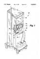
- FIG. 1is a perspective view of a dialysis machine which incorporates the present invention.
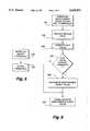
- FIG. 2is a block diagram of a control system and a safety system of a dialysis machine shown in FIG. 1.
- FIG. 3is a generalized view illustrating some of the typical components of an extracorporeal flow path and a hydraulics flow path of the dialysis machine shown in FIGS. 1 and 2.
- FIG. 4is a more detailed diagram of more of the components of the hydraulics and extracorporeal flow paths shown in FIG. 3.
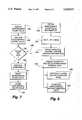
- FIG. 5is a flow chart illustrating actions involved in establishing or modifying a threshold to evaluate the condition of the components which are subject to the trend analysis of the present invention.
- FIG. 6is a flow chart illustrating actions involved in detecting events that describe the condition of the components which are subject to the trend analysis according to the present invention.
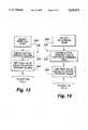
- FIG. 7is a flow chart illustrating actions involved in analyzing the condition of the components which are subject to trend analysis according to the present invention.
- FIG. 8is a flow chart illustrating actions involved in predicting the failure or malfunction of the components which are subject to trend analysis according to the present invention.
- FIG. 9is a flow chart illustrating the actions shown in FIG. 6 of computing a test value for a duty cycle driven pump in an extracorporeal flow path or a hydraulics flow path shown in FIGS. 3 and 4.
- FIG. 10is a flow chart illustrating the actions shown in FIG. 6 of computing a test value for two flow meters in a hydraulics flow path shown in FIGS. 3 and 4.
- FIG. 11is a flow chart illustrating the actions shown in FIG. 6 of computing a test value for gear pumps in a hydraulics flow path shown in FIGS. 3 and 4.
- FIG. 12is a flow chart illustrating the actions shown in FIG. 6 of computing a test value for a pump ultrafiltration feedback value in a hydraulics flow path shown in FIGS. 3 and 4.
- FIG. 13is a flow chart illustrating the actions shown in FIG. 6 of computing a test value for a sterilant pump in a hydraulics flow path shown in FIGS. 3 and 4.
- FIG. 14is a flow chart illustrating the actions shown in FIG. 6 of computing a test value for a degassing pump in a hydraulics flow path shown in FIGS. 3 and 4.
- the present inventionis advantageously incorporated in a dialysis machine, such as that shown generally at 20 in FIGS. 1 and 2.
- the dialysis machine 20is used to perform a variety of different and well-known dialysis treatments on a patient.
- the dialysis machine 20includes a control system 22 and a safety system 24.
- the functions of the control system 22are accomplished substantially by an extracorporeal microcontroller 26 and a hydraulics microcontroller 28.
- the functions of the safety system 24are performed by a safety system microcontroller 30.
- Each microcontroller 26, 28 and 30includes its own memory 32, 34 and 36, respectively, in which programs are recorded for controlling the microcontrollers and the components of the dialysis machine 20.
- the safety system memory 36includes a nonvolatile or permanent portion to prevent the loss of functionality after recovering from an unexpected power failure.
- Control and safety informationis supplied to the dialysis machine through an operator/machine interface (OMI) 38.
- OMI 38includes an input/output (I/O) device 40 through which the entered information is supplied to the protective microcontroller 30 and from which operating and safety information is displayed to the operator.
- the OMI 38may also include its own processor for assisting in the input and output of information. Information is directly transferred and shared between the microcontrollers 26, 28 and 30 over a bus or network 42.
- the components of the dialysis machine 20establish an extracorporeal flow path and a hydraulics flow path, which are shown in FIGS. 3 and 4. Blood from the patient flows through the extracorporeal flow path where it is cleansed and then returned to the patient. Dialysate flows through the hydraulics flow path to remove the wastes transferred to the dialysate.
- the extracorporeal flow pathincludes sensors 44 and control devices 46 to sense blood flow conditions and control the blood flow.
- the hydraulics flow pathalso includes sensors 48 and control devices 50 to sense conditions of the dialysate and control its characteristics.
- the sensors 44 and 48 and the control devices 46 and 50 in the extracorporeal and the hydraulics flow pathsare connected to the microcontrollers of both the control system 22 and the safety system 24. Should either the control system 22 or the safety system 24 experience a malfunction, the other system can assume control over the dialysis machine 20 and place it in a safe patient state where the risk to the patient is eliminated or minimized.
- FIGS. 3 and 4Blood flows from a patient 52 through a conventional dialyzer 54 and back to the patient 52.
- An arterial blood pump 56(usually peristaltic, as shown) draws blood from the patient 52 through an arterial line 58 and into an arterial chamber 60 of a blood handling cartridge 62.
- the blood pump 56draws blood from the arterial chamber 60 through a pump tubing 64 which is squeezed or pinched by a rotating rotor 66 against a stationary raceway 68.
- the blood within the pump tubing 64is propelled into a manifold 70 of the blood handling cartridge 62 and then through a tube 72 and into a blood inlet of the dialyzer 54.
- a micro-porous or other type of dialysis medium 74divides the interior of the dialyzer 54 into a blood chamber 76 and a dialysate chamber 78. While in the dialyzer 54, the waste products from the patient 52 are separated from the blood, and the cleansed blood is transferred back to a venous chamber 80 of the cartridge 62 through a tube 82. Any unintentionally introduced air in the blood is extracted while in the venous chamber 80.
- a venous line 84After leaving the venous chamber 80 the blood flows through a venous line 84 to an air detector 86.
- the air detector 86derives signals related to the quantity of air, if any, remaining in the venous line 84. If an excessive amount of air is present, a protective control signal will be generated and a venous line clamp 88 will immediately close to terminate the flow of blood through the venous line 84 before the air reaches the patient 52.
- a venous blood pump 90(FIG. 4) is located in the venous line 84 to assist in returning the blood to the patient 52.
- An arterial clamp 92is located in the arterial line 58 for the purpose of stopping the flow of blood in the arterial line 58 when necessary or desired.
- an anticoagulantsuch as heparin is injected into the extracorporeal flow path.
- the anticoagulantis slowly delivered from a syringe 94.
- a plunger 96is displaced into the syringe 94 by a driver mechanism (not shown).
- the driver mechanism and the syringe 94are typically referred to as a heparin pump or an anticoagulant pump.
- the components of the hydraulics flow pathare also shown in greater detail in FIGS. 3 and 4.
- the hydraulics flow pathincludes a dialysate pump 100 which draws dialysate from a supply 102.
- the supply 102 of dialysateis prepared by the dialysis machine from purified water and a supply of chemicals, or is obtained from an external source of previously prepared dialysate.
- the dialysate pump 100delivers the dialysate through a dialysate supply line 104 to the dialysate chamber 64 of the dialyzer 54.
- the dialysateflows past the medium 74 where it absorbs the waste products transferred from the blood in the blood chamber 76. Any beneficial components in the dialysate which are to be transferred into the blood pass through the medium 74 and into the blood in the blood chamber 76.
- Dialysate containing the waste productsis removed from the dialysate chamber 78 by a drain pump 106 which is connected to the dialyzer 54 by a dialysate drain line 108.
- the used dialysate in the dialysate drain line 108is delivered to a waste drain 110.
- the waste drain 110may be a separate container or a connection to a public sewer.
- a heater 112is located in the dialysate supply line 104.
- the heater 112raises the temperature of the dialysate supplied to the dialyzer 54 to a temperature commensurate with the body temperature of the patient 52. Heat transfer between the blood and the dialysate in the dialyzer 54 is avoided in this manner to prevent thermal distress in the patient.
- the heater 112also functions during disinfection of the hydraulics flow path. During disinfection, any microorganisms which might be found in the hydraulics flow path are destroyed. A solution of sterilant, which is formed from disinfecting chemicals, is directed through the hydraulics flow path. Frequently the sterilant will also be heated to aid in destroying the microorganisms.
- the heater 112is employed to heat the sterilant under disinfecting conditions.
- the hydraulics flow pathalso includes a number of flow control valves (many of which are not shown), and a number of sensors (many of which are not shown) for determining characteristics of the dialysate, such as conductivity sensors, pH sensors, temperature sensors and others, all of which are generally known in the field of dialysis machines.
- the hydraulics flow pathcontains many of the components which are subject to the trend analysis. More details concerning the functionality of those components are discussed below specifically with regard to their characteristics which make them susceptible to trend analysis.
- the trend analysis technique of the inventioninvolves monitoring a characteristic operating parameter of a component of the dialysis machine and comparing the monitored characteristic to a threshold value. Should the monitored characteristic deviate from the threshold value, an abnormal event will be recognized. The occurrence of the abnormal event will increment a maintenance counter. The maintenance counter will record information relating to each abnormal event occurring during use of the dialysis machine. The information from the maintenance counter is analyzed to make decisions concerning the replacement or service of the component subject to the trend analysis.
- the threshold valueis generally a value representing the level or range of acceptable performance of the component. The threshold value is established by the operator or the manufacturer of the dialysis equipment for determining whether the monitored characteristic operating parameter of the component represents an unacceptable deviation from the normal characteristics.
- Predictions of component failureare obtained by calculating or observing a trend value related to the change in the maintenance count value relative to another parameter such as time. The trend will be evaluated as a basis to predict or estimate the failure of the component and to estimate a date or time for replacing that component. Such predictions can also be employed to generate an alarm to alert the maintenance personnel of the necessity to replace the component.
- FIGS. 5-8The basic features of the invention are shown in FIGS. 5-8. Specific features involved in certain basic features are shown in FIGS. 9-14. Some of the activities involved in the invention are actions that are taken or that may be taken by the maintenance personnel for the dialysis machine, and some of the actions are or may be performed by the control system and safety system of the dialysis machine. Aspects of the invention are shown as steps in the flow charts of FIGS. 5-8, and each of the steps is separately designated by a reference numeral for convenience of description.
- each thresholdrepresents the tolerance limit or range of normal operation of the component subject to trend analysis.
- the threshold value entered at 120is stored into memory, preferably permanent memory, at 122.
- the permanent memoryis part of the memory 36 (FIG. 2) connected to the protective microcontroller 30. Storing the threshold values in nonvolatile memory protects them against loss or destruction from unanticipated power outages and other malfunctions. The threshold values are therefore available over extended periods of time.
- the basic features shown in FIG. 6involve detection of abnormal events which indicate operation of the component beyond the threshold.
- the sequence of events shown in FIG. 6occurs during each operation of the dialysis machine.
- the threshold value of each component under analysisis downloaded or transferred from the protective memory 36 (FIG. 2) to the extracorporeal microcontroller 26 and/or the hydraulics microcontroller 28 over the network 42.
- information or data from the extracorporeal sensor devices 44 (FIG. 2) and the hydraulics sensor devices 48is supplied at 126 to the microcontrollers 26 and 28.
- the sensor datais available for each of the components analyzed.
- a test valueis computed or calculated at step 128 by using the sensor data supplied at 126 or the commanded values of a parameter supplied to the component (e.g. the duty cycle of energizing power supplied to a stepper motor) and the threshold value obtained at 124.
- the test valueis that value which represents the operating circumstances of each component under the specific conditions. In some circumstances described below, the test value computed at 128 will be the data received from the sensors at 126. In other cases described below, the test value at 128 will result from a mathematical calculation performed using the sensor data received at 126. Consequently, the test value generally must be calculated for each component depending upon its actual operating conditions.
- the steps for calculating the test values for a number of different components which will normally be subject to trend analysis in a dialysis machineare shown and separately described in conjunction with FIGS. 9-14.
- a comparison of the test value calculated at 128 to the threshold valueis performed at 130. If the comparison at 130 reveals that the test value exceeds or falls outside of the limits of the threshold, an abnormal event has occurred and a maintenance count value is incremented at 132.
- the maintenance count valueis a value recorded in the memory which represents the total number of abnormal events that have occurred when the operating conditions of the component under analysis exceeded the threshold or normal operating tolerances. For prediction purposes, the time and date of each abnormal event are also preferably recorded along with the fact of the occurrence of such abnormal event. If the comparison at 130 reveals that the test value is not uniquely different from the threshold, the maintenance count value is not incremented.
- the maintenance count valueis recorded in memory, as shown at 134.
- the maintenance count value in memoryis updated by transferring the information over the network 42 (FIG. 2).
- FIG. 7The basic features of the invention which relate to analyzing each component are illustrated in FIG. 7.
- the operatorrequests a display or other presentation of the maintenance count value for a selected one or more of the components.
- the displayis accessed through the OMI I/O devices 40 (FIG. 2) which are connected to the protective microcontroller 30 to receive the maintenance count value from memory.
- the operatorAfter obtaining the information requested at 136 the operator analyzes the maintenance count value at 138.
- the analysis performed at step 138may be as simple as recognizing an excessive maintenance count value. More complex types of analysis may involve extrapolating the count value and dates associated with the abnormal events to predict a date of failure.
- the operatormay schedule preventive maintenance based on the predicted date of failure, or take other actions based on the experience and judgment.
- the control and safety system microcontrollers 26, 28 or 30(FIG. 2) may perform the analysis or the operator or a service technician may perform the analysis to analyze the condition of the component.
- An example of the type of analysis action which the operator may takeis shown by the steps 140, 142, 144 and 146. If the maintenance count is too high, as determined at 140, the operator may replace the component as shown at 142. Thereafter the operator resets the maintenance count value for the replaced component, as shown at 144. The reset maintenance count value is thereafter stored in memory as shown at 146. If the maintenance count value is not too high as determined at 140, the maintenance count value is left unmodified and the normal operation of the machine proceeds from the outcome 148 of the determination at 140.
- the actions of requesting the maintenance count value at 136, resetting the maintenance count value at 144 and storing the reset maintenance count value back to the memoryis accomplished by the operator using the I/O devices 40 (FIG. 2).
- the basic features involved in predicting component failure or replacement and scheduling maintenance before the anticipated date of failureare shown in FIG. 8.
- the steps shownmay be performed entirely by the functionality of the control and safety system microcontrollers, or the steps may be performed manually, or the information may be downloaded from the dialysis machine and the steps performed by a separate computer. A combination of manual and automatically executed steps may also be employed.
- the maintenance count value informationis first obtained at 150.
- the maintenance count value informationincludes the count value, and in this case, the dates associated with each abnormal event which gave rise to an increase in the maintenance count value. From this information, a trend in the occurrence of abnormal events is calculated at 152. The trend may project the rate of abnormal events forward in time.
- the expected lifetime or maintenance interval information for the individual component under considerationis obtained, as shown at 154.
- the expected lifetime or maintenance interval informationmay be supplied in memory with the dialysis machine, or may be entered or updated by the operator based on the experience of the operator with maintenance of the dialysis machine, or may be stored elsewhere on a different computer or in a different source of information.
- the expected lifetime or maintenance interval informationis employed in a calculation or other extrapolation based on the trend obtained at 152. Based on experience, empirical information or estimates and the count value, trend and expected lifetime or service intervals, the projected lifetime or service interval may be projected.
- an alarmis scheduled at 158 to be delivered before the expected failure date or maintenance interval date.
- the alarm at 158may be scheduled automatically by the control and safety system microcontrollers, in which case the alarm will also be delivered automatically based on the scheduled date, as calculated by the normal system clock maintained by the microcontroller. Otherwise, the operator manually schedules the alarm date.
- Maintenancemay also be scheduled at the same time as the alarm is scheduled at 158, or at a different earlier time from the alarm or expected failure or maintenance interval date determined at 156. By predicting failure or maintenance interval dates, a number of components having failure or maintenance interval dates occurring at comparable times may be serviced or replaced at the same time, thereby reducing the number of service calls. Scheduling the maintenance is shown at 160. Again, the system microcontrollers may schedule the dates for the maintenance or the scheduling might be done manually by the operator.
- the trend analysis informationcan be accessed by a maintenance person during regularly scheduled maintenance events when the machine is not used in treatments, or the information can be accessed to evaluate the condition of the dialysis machine.
- the trend analysis informationmay be downloaded from the dialysis machine to a central maintenance computer or station and evaluated there.
- the on time of the duty cyclerepresents the amount of electrical power necessary to drive the motor. As the motor wears and as the pump which is driven by the motor wears, the amount of electrical power to achieve the desired performance is increased to compensate for the wear. Since most of the components of the dialysis machine include sensors (44 and 46, FIG. 2) to measure the performance of the component, and the extracorporeal and hydraulics microcontrollers (26 and 28, FIG. 2) utilize the sensor information to control the pumps and thereby achieve the desired flow rates, the on time of the duty cycle is readily adjustable to overcome the effects of wear. By monitoring the on time of the duty cycle and comparing that on time to the expected on time for a normally operating pump, the degree or extent of wear is readily determinable.
- Examples of pumps in the dialysis machinewhich may be driven by a stepper motor energized on a duty cycle basis are the arterial blood pump 56, the venous blood pump 90 or infusate pump, the dialysate flow pump 100, the drain flow pump 106, a degassing pump 162, and one or more chemical supply pumps 164, all shown in FIG. 4.
- a dialysis machineemploys two chemical supply pumps 164, but only one is shown in FIG. 4.
- One chemical supply pumpusually supplies bicarbonate from a chemical supply 166.
- the other chemical supply pumptypically supplies acid from a separate chemical supply.
- the bicarbonate, acid or other chemicalis mixed with water from a supply 168 to form the dialysate.
- Each chemical supply pump 164is required to deliver precise quantities of the chemical to be mixed with the water and thereby achieve the desired composition of the dialysate. All of the components shown in FIG. 4 which are employed to prepare the dialysate are generally shown in FIG. 3 at 102.
- the duty cycle driven flow pumps 100 and 106 and the degassing pump 162have associated with them a flow sensor to measure their performance.
- a flow sensor 170is located in the flow path where the degassing pump 162 circulates fluid around the heater 112.
- Flow sensors 174 and 176are located in the dialysate supply line 104 and the dialysate drain line 108 to monitor the volumetric flow rates of the dialysate flow pumps 100 and 106.
- a sensor 172is associated with the chemical supply pump 164 to measure its rotational rate and to thereby determine the volumetric flow conducted by that pump 164.
- Sensors 174 and 176are associated with the arterial blood pump 56 and venous blood pump 90 to measure the rotational rate of those pumps 56 and 90. From the rotational rates, the volumetric flow rate of the blood in the arterial line 58 and the venous line 84 is determined.
- the sensors 170, 174 and 176are typically hall sensors which sense the movement of the rotors of the pumps with which may are associated.
- the sensors 170, 172, 174, 176, 177 and 178are included in the extracorporeal and hydraulic sensor devices 44 and 48 shown in FIG. 2.
- the computation 128 of the test value for one of the duty cycle driven pumpsis shown in greater detail in FIG. 9.
- the duty cycle driven pumpis selected at 180, and the data from the sensor associated with the blood pump is obtained at 182.
- the actual sensor data obtained at 182is that data which represents the actual operating performance of the duty cycle driven pump.
- the percentage of the on or conductive time in each duty cycle which drives the pumpis monitored relative to the performance of the pump under the specific operating conditions.
- the specific operating conditionstake into account the flow of fluid, the pressure of the fluid at the location of the pump, and other variables which influence the performance of the pump under those circumstances.
- the ideal value of the duty cycle on time for driving the pump under those same circumstancesis recorded in a table in memory. The ideal value is obtained from the memory table at 184.
- the test valueis computed as the difference between the ideal value obtained at 184 and the actual value obtained from the sensor data at 182. This difference, which is determined at 186, becomes the test value. The test value therefore represents the difference between the actual operating value and the value which results from ideal conditions.
- the threshold established(step 120, FIG. 5)
- the threshold established for a duty cycle driven pumpwill be a range of acceptable deviation.
- test value obtained at 186is compared with the range of acceptable deviations represented by the threshold at 130 in FIG. 6. Test values which exceed (fall outside of) the threshold range indicate the occurrence of an abnormal event which increments the maintenance count value at 132 (FIG. 6).
- the computation 128 of the test value for the flow sensors or meters 177 and 178 (FIG. 4) in the hydraulics flow pathis shown in greater detail in FIG. 10.
- the selection of the flow meters for considerationis shown at 190.
- the actual sensor data obtained from the two flow metersis obtained at steps 192 and 194.
- the actual sensor data obtained at 192 and 194is used to calculate a ratio of the two values known as a taration constant, as shown at 196.
- the taration constantestablishes a normalized tare value for comparing the relative performance of both flow meters 177 and 178. Under ideal testing conditions, the flow through each flow meter should be equal, and the resulting taration constant will be 1.0.
- the hydraulics microcontrollerAfter calculation of the taration constant at 196, the hydraulics microcontroller subtracts the value of 1.0 from the taration constant, as shown at 198. The result of this subtraction is the test value, and the program flow thereafter continues at step 130 (FIG. 6).
- the threshold established at 124will constitute a normal range of deviation which is considered acceptable. Variations in the test value calculated at 198 which exceed (fall outside of) the threshold will be considered abnormal and will result in the incrementation of the maintenance count value, as shown at 130 and 132 in FIG. 6.
- the trend analysis information available from this inventionmay indicate that the flow meters should be cleaned of this buildup.
- the trend analysis information available concerning the flow metersmay also be employed to recognize malfunctions or errors in the sensors which measure the flow through the flow meters.
- the computation 128 of the test value for the performance of the flow pumps 100 and 106(FIGS. 3 and 4) apart from the electrical motors which drive those pumps, is shown in greater detail in FIG. 11.
- These electrical motorsare duty cycle driven, as described above.
- the flow producing components of these pumpsare usually gears or impellers.
- the gears or impellersare also subject to wear, and the test value computed in FIG. 11 is an effective means for determining the condition of those gears or impellers.
- the selection of the gear pumps or impeller pumps for trend analysisis shown at 200.
- the hydraulic pressure on both pumpsmust be equal.
- the performance of gear or impeller pumpsis pressure dependent, so an unequal pressure will prevent an accurate evaluation of the pumps.
- the step at 202allows the computation of the test value to occur only when the pressures on both pumps are made equal.
- both gear pumpsexperiencing the same pressure, they are operated at the same rpm, and the on time of the energizing duty cycle for each pump is obtained at 204.
- the two duty cycle values obtained at 204are then divided to obtain a ratio as shown at 206.
- a unity ratioindicates that both gear pumps are operating similarly. The greater the deviation of the ratio from unity indicates a greater disparity in pump operation.
- the ratio obtained at 206is subtracted from unity at step 208, and the result is the test value. Since the ratio established at 206 is the ratio of the first pump duty cycle (P1) to the second pump duty cycle (P2), the test value obtained at 208 indicates both proper operation and which one of the two pumps is failing. A zero test value indicates that both pumps are operating adequately. A negative test value indicates that the second pump (P2) is failing because the ratio calculated at 206 is a value greater than 1.0. A positive test value indicates that the first pump (P1) is failing because the ratio calculated at 206 is a value less than 1.0.
- the test value obtained at 208is employed at step 130 in the flow shown in FIG. 6.
- the threshold established at 120(FIG. 5) represents an acceptable range of variability in the relative performance of the two gear pumps. Consequently, the threshold downloaded at 124 (FIG. 6) will be a range of deviations with which the test value obtained at 208 (FIG. 11) is compared at 130. Test values falling outside of the range of the threshold indicate the occurrence of an abnormal event which increments the maintenance count value at 132 (FIG. 6).
- Ultrafiltrationis typically a part of a dialysis treatment in which fluid components from the blood are drawn through the medium 74 and into the dialysate, as is understood from FIGS. 3 and 4.
- the typical method of obtaining ultrafiltrationis to create a different flow out of the dialysate outlet of the dialyzer 54 compared to the dialysate flow into the inlet of the dialyzer.
- the ultrafiltration pump 210shown in FIG. 4, is employed during ultrafiltration to create the differential in dialysate flows into and out of the dialyzer 54.
- the ultrafiltration pump 210is connected between the dialysate supply line 108 and the dialysate drain line 110. Operation of the ultrafiltration pump 210 increases or decreases the flow of dialysate out of the dialyzer at the outlet of the dialyzer.
- the ultrafiltration pump 210is employed because it is usually the case that both flow pumps 100 and 106 are operated at the same rate.
- the operation of the ultrafiltration pump 210establishes the rate of ultrafiltration independently of the rates of operation of the dialysate supply and drain pumps.
- the ultrafiltration pump 210is operated while the dialysate supply and drain pumps 100 and 106 also operate.
- the flow ratesare measured by the sensors 177 and 178 until the flow rates are equal.
- the value of the control signal to the ultrafiltration pump 210is determined under this condition and that value is established as a unity (1.0) UPFBV.
- the UPFBVis adjusted to achieve the desired accuracy of ultrafiltration. This adjusted rate is then employed to evaluate the performance of the ultrafiltration pump after the conclusion of the treatment.
- the computation of the test value 128 for the UPFBVis shown in greater detail in FIG. 12.
- the ultrafiltration pumpis selected for analysis at 220.
- the actual UPFBV value which resulted from the adjustment during the previous ultrafiltration treatmentis obtained at 222, by reading the UPFBV value from memory.
- the actual UPFBV value obtained at 222is subtracted from unity (1.0) and the result is the test value, as shown at 224.
- the program flowcontinues at step 130 shown in FIG. 6.
- the UPFBV threshold established at 120(FIG. 5) will constitute a normal range of deviation which is considered acceptable operation for the ultrafiltration pump. Variations in the test value calculated at 224 (FIG. 12) beyond the threshold obtained at 124 (FIG. 6) will be considered as abnormal events which will increment the maintenance count value at 132 (FIG. 6). Instances where the maintenance count value for the UPFBV is incremented are those which may arise do to control malfunctions in the ultrafiltration pump 210 as well as malfunctions in the pump 210 itself.
- the computation 128 of a test value for a sterilant pump 226is shown in greater detail in FIG. 13.
- the sterilant plump 226is used to deliver a predetermined amount of sterilant from a supply 228 to the hydraulics flow path for cleaning and disinfecting the hydraulics flow path before the dialysis machine is used. It is important that the quantity of sterilant supplied by the sterilant pump 226 be accurately measured because the proper concentration is necessary to achieve adequate disinfection.
- the sterilant pump 226is connected to the sterilant supply 228 by a three way valve 230.
- the source of sterilant 228is also connected to the valve 230.
- a burette 232is connected to the sterilant pump 226.
- the valve 230When it is desired to deliver sterilant to the hydraulics flow path, the valve 230 is operated to connect the sterilant pump 226 to the sterilant source 228.
- the sterilant pump 226is preferably a peristaltic pump. The rotational movement of the rotor of the peristaltic pump results in moving a constant volume of fluid through the pump. This constant volume is referred to as a "stroke.” Each stroke of the pump 226 withdraws a predetermined volume of sterilant from the source 228 which is transferred to the burette 232. The sterilant fills the burette to a level determined by an optical sensor 234 positioned adjacent to the burette 232.
- the signals from the optical sensor 234represent the volume of sterilant in the burette which was created by a predetermined number of strokes of the sterilant pump 226. As the sterilant pump experiences wear, the stroke volume will vary, usually decreasing. The stroke volume is the parameter which is measured to perform the trend analysis on the sterilant pump 226.
- the computation 128 of the test value for the sterilant pumpbegins with the sterilant pump being selected for the trend analysis at 240.
- the value of the stroke volumeis obtained from the level to which the burette is filled with sterilant, as shown at 242.
- the test valueis thereafter made equal to the stroke volume at 244. With the test value for the sterilant pump established, the program flow progresses to step 130 shown in FIG. 6.
- the threshold established for the sterilant pump at step 120is the predetermined desired stroke volume. If the test value established at step 244 (FIG. 13) is less than the threshold as determined at 130 (FIG. 6), the maintenance count value is incremented at 132 (FIG. 6).
- the threshold establishedcould also be a range of stroke volumes which are acceptable, in the case where a malfunctioning or failing sterilant pump could be revealed by a larger than desired stroke volume or a smaller than desired stroke volume.
- the computation 128 of a test value for the degassing pump 162(FIG. 4) is shown in greater detail in FIG. 14.
- the degassing pump 162is used in conjunction with the heater 112 to recirculate fluid around the heater 112.
- the degassing pump 162is used during dialysis treatments to remove any air which may have entered the hydraulics flow path.
- the degassing pump 162is typically driven by a direct current motor.
- the speed or rpm of the degassing pump motoris directly related to the quantity of current supplied to the motor.
- a predetermined rpm of the degassing pump motorestablishes the desired pressure within the flow path through the heater 112. The amount of current to establish this desired rpm is read and is used as the parameter by which to analyze the trend characteristics of the degassing pump.
- the degassing pumpis selected for trend analysis at 250 in FIG. 14.
- the actual value or quantity of current required to drive the pump at that desired rpmis read at 252.
- the test valueis then set equal to the actual current value at 254.
- the test value established at 254is then employed in the program flow at step 130 shown in FIG. 6.
- the threshold established at 120 (FIG. 5) for the degassing pumpis a range of acceptable values for the current required to drive the degassing pump at the predetermined rpm. If the test value falls outside of the range of the threshold, as determined at 130 (FIG. 6), an abnormal event is indicated and the maintenance count value is incremented at 132 (FIG. 6).
- a number of components of a dialysis machinehave been discussed as susceptible for trend analysis, other components could also be evaluated using the present invention.
- parameters other than those discussed abovecould be selected by which to evaluate the performance of the component under analysis.
- a suitable parameterwill be one which is supplied to the component and to which the component responds by delivering the intended performance or functionality.
- the present inventionmay be practiced adequately using any parameters of this nature on any component within the dialysis machine.
- Use of the present invention with dialysis machinesoffers the capability of reducing maintenance costs associated with the machines.
- Components which are likely to failmay be replaced or serviced at regularly scheduled maintenance intervals, rather than at special or emergency maintenance calls. Multiple components may be replaced at one time if the trend analysis indicates that failure is imminent, rather than encountering the necessity for separate special service calls as each component fails at a different time.
- the regular service schedulescan be adjusted to avoid unexpected failures.
- Dialysis machines in dialysis clinicsmay be maintained in a manner which avoids downtime during the period of the day when patients normally receive treatment. As a result, the costs of operating the dialysis equipment may be reduced or the rate of increase may be reduced. Many other significant improvements will be recognized after the present invention is fully appreciated.
Landscapes
- Health & Medical Sciences (AREA)
- Heart & Thoracic Surgery (AREA)
- Vascular Medicine (AREA)
- Engineering & Computer Science (AREA)
- General Health & Medical Sciences (AREA)
- Biomedical Technology (AREA)
- Public Health (AREA)
- Hematology (AREA)
- Life Sciences & Earth Sciences (AREA)
- Animal Behavior & Ethology (AREA)
- Veterinary Medicine (AREA)
- Anesthesiology (AREA)
- Urology & Nephrology (AREA)
- Cardiology (AREA)
- Emergency Medicine (AREA)
- Physics & Mathematics (AREA)
- Epidemiology (AREA)
- Medical Informatics (AREA)
- Primary Health Care (AREA)
- Business, Economics & Management (AREA)
- General Business, Economics & Management (AREA)
- General Physics & Mathematics (AREA)
- Nuclear Medicine, Radiotherapy & Molecular Imaging (AREA)
- Surgery (AREA)
- External Artificial Organs (AREA)
Abstract
Description
Claims (29)
Priority Applications (5)
| Application Number | Priority Date | Filing Date | Title |
|---|---|---|---|
| US08/486,942US5629871A (en) | 1995-06-07 | 1995-06-07 | Wear trend analysis technique for components of a dialysis machine |
| CA002217998ACA2217998A1 (en) | 1995-06-07 | 1996-06-06 | Wear trend analysis technique for components of a dialysis machine |
| PCT/US1996/009218WO1996040316A1 (en) | 1995-06-07 | 1996-06-06 | Wear trend analysis technique for components of a dialysis machine |
| EP96917236AEP0830154A1 (en) | 1995-06-07 | 1996-06-06 | Wear trend analysis technique for components of a dialysis machine |
| JP50159597AJP4049813B2 (en) | 1995-06-07 | 1996-06-06 | Wear trend variation analysis technology for dialysis machine components |
Applications Claiming Priority (1)
| Application Number | Priority Date | Filing Date | Title |
|---|---|---|---|
| US08/486,942US5629871A (en) | 1995-06-07 | 1995-06-07 | Wear trend analysis technique for components of a dialysis machine |
Publications (1)
| Publication Number | Publication Date |
|---|---|
| US5629871Atrue US5629871A (en) | 1997-05-13 |
Family
ID=23933748
Family Applications (1)
| Application Number | Title | Priority Date | Filing Date |
|---|---|---|---|
| US08/486,942Expired - LifetimeUS5629871A (en) | 1995-06-07 | 1995-06-07 | Wear trend analysis technique for components of a dialysis machine |
Country Status (5)
| Country | Link |
|---|---|
| US (1) | US5629871A (en) |
| EP (1) | EP0830154A1 (en) |
| JP (1) | JP4049813B2 (en) |
| CA (1) | CA2217998A1 (en) |
| WO (1) | WO1996040316A1 (en) |
Cited By (60)
| Publication number | Priority date | Publication date | Assignee | Title |
|---|---|---|---|---|
| WO1999046593A1 (en)* | 1998-03-10 | 1999-09-16 | Baxter International Inc. | Systems and methods for monitoring and analyzing operation of medical processing devices |
| US6146523A (en)* | 1995-02-13 | 2000-11-14 | Aksys, Ltd. | User interface and method for control of medical instruments, such as dialysis machines |
| US6226597B1 (en)* | 1996-11-27 | 2001-05-01 | Hamilton Sundstrand Corporation | Method of maintaining components subject to fatigue failure |
| US6256643B1 (en) | 1998-03-10 | 2001-07-03 | Baxter International Inc. | Systems and methods for storing, retrieving, and manipulating data in medical processing devices |
| US20020029115A1 (en)* | 2000-09-07 | 2002-03-07 | Mori Seiki Co., Ltd. | Machine tool maintenance system |
| US20020161457A1 (en)* | 2001-02-20 | 2002-10-31 | General Electric Company | Method and apparatus for estimating time to failure acceleration factor |
| US20030046439A1 (en)* | 2000-03-20 | 2003-03-06 | Joachim Manke | Medical device with dual communications bus |
| WO2001084506A3 (en)* | 2000-05-01 | 2003-04-24 | Gen Electric | System and method for managing mobile assets |
| USD483872S1 (en) | 2002-09-27 | 2003-12-16 | Baxter International Inc. | Display portion for a medical machine |
| USD484982S1 (en) | 2002-09-27 | 2004-01-06 | Baxter International Inc. | Chassis for a medical machine |
| US6708138B1 (en)* | 1998-08-28 | 2004-03-16 | Mitutoyo Corporation | Maintenance-and-control apparatus and method for coordinate and surface texture measuring device |
| US20040064080A1 (en)* | 2002-09-27 | 2004-04-01 | Edward Cruz | Dialysis machine having combination display and handle |
| USD492034S1 (en) | 2002-09-27 | 2004-06-22 | Baxter International Inc. | Base for a medical machine |
| US20040162646A1 (en)* | 1997-01-28 | 2004-08-19 | American Calcar Inc. | Multimedia information and control system for automobiles |
| FR2853980A1 (en)* | 2003-04-16 | 2004-10-22 | Geyser | Medical apparatus e.g. medical inflators, operational incidents recording method, involves storing operational parameters, storing data recorded during incident occurrence, and recording detected defects of inflator components |
| US20040260790A1 (en)* | 2000-12-21 | 2004-12-23 | Ge Medical System Global Technology Company, Llc | Method and apparatus for remote or collaborative control of an imaging system |
| US20050165519A1 (en)* | 2004-01-28 | 2005-07-28 | Ariyur Kartik B. | Trending system and method using window filtering |
| US7127499B1 (en)* | 1998-11-25 | 2006-10-24 | General Electric Company | Medical diagnostic system service method and apparatus |
| US20060265180A1 (en)* | 2005-03-04 | 2006-11-23 | Sandor Dolgos | Dialysis machine with servicing indicator |
| US20070000824A1 (en)* | 2005-03-23 | 2007-01-04 | Gerhard Bock | Blood treatment apparatus with alarm device |
| DE102006011346A1 (en)* | 2006-03-11 | 2007-09-13 | Fresenius Medical Care Deutschland Gmbh | Method and device for operating an electric peristaltic peristaltic pump |
| KR100827496B1 (en) | 2007-03-23 | 2008-05-06 | (주) 비에이치케이 | Slide type blood filtration device |
| US7383358B1 (en)* | 1999-12-29 | 2008-06-03 | Ge Medical Technology Services, Inc. | System and method for remote servicing of in-field product |
| US20090119066A1 (en)* | 2007-11-06 | 2009-05-07 | Strong Alvin D | Providing directive replacement of hfsi parts based on specific machine performance |
| US20090312694A1 (en)* | 2008-06-11 | 2009-12-17 | Baxter International Inc. | Distributed processing system and method for dialysis machines |
| USD611137S1 (en)* | 2007-06-19 | 2010-03-02 | Gambro Lundia Ab | Dialysis machine and display |
| US20100066981A1 (en)* | 2006-10-04 | 2010-03-18 | Nec Display Solutions, Ltd. | Projector and method of cooling light source of projector |
| DE102008039022A1 (en) | 2008-08-21 | 2010-04-15 | Fresenius Medical Care Deutschland Gmbh | A method and apparatus for monitoring a peristaltic peristaltic pump for delivering a fluid in a tubing |
| US20100252490A1 (en)* | 2008-09-12 | 2010-10-07 | Fulkerson Barry N | Modular Reservoir Assembly for a Hemodialysis and Hemofiltration System |
| WO2011069645A1 (en)* | 2009-12-11 | 2011-06-16 | Fresenius Medical Care Deutschland Gmbh | Device and method for monitoring an electrically operated pump arranged in a liquid system of an extracorporeal blood treatment device |
| US20130049974A1 (en)* | 2011-08-29 | 2013-02-28 | Martin Joseph Crnkovich | Early detection of low bicarbonate level |
| US8395761B2 (en) | 2007-10-11 | 2013-03-12 | Fresenius Medical Care Holdings, Inc. | Thermal flow meter |
| US20130155834A1 (en)* | 2011-12-20 | 2013-06-20 | Ncr Corporation | Methods and systems for scheduling a predicted fault service call |
| US8535522B2 (en) | 2009-02-12 | 2013-09-17 | Fresenius Medical Care Holdings, Inc. | System and method for detection of disconnection in an extracorporeal blood circuit |
| US8597505B2 (en) | 2007-09-13 | 2013-12-03 | Fresenius Medical Care Holdings, Inc. | Portable dialysis machine |
| US8771511B2 (en) | 2007-11-29 | 2014-07-08 | Fresenius Medical Care Holdings, Inc. | Disposable apparatus and kit for conducting dialysis |
| WO2014159196A3 (en)* | 2013-03-14 | 2014-12-24 | Carefusion 303, Inc. | Predictive maintenance for medical devices |
| US9081656B2 (en) | 2011-12-20 | 2015-07-14 | Ncr Corporation | Methods and systems for predicting a fault |
| US9157786B2 (en) | 2012-12-24 | 2015-10-13 | Fresenius Medical Care Holdings, Inc. | Load suspension and weighing system for a dialysis machine reservoir |
| US9295772B2 (en) | 2007-11-29 | 2016-03-29 | Fresenius Medical Care Holdings, Inc. | Priming system and method for dialysis systems |
| US9308307B2 (en) | 2007-09-13 | 2016-04-12 | Fresenius Medical Care Holdings, Inc. | Manifold diaphragms |
| US9328969B2 (en) | 2011-10-07 | 2016-05-03 | Outset Medical, Inc. | Heat exchange fluid purification for dialysis system |
| US9354640B2 (en) | 2013-11-11 | 2016-05-31 | Fresenius Medical Care Holdings, Inc. | Smart actuator for valve |
| US9352282B2 (en) | 2007-09-25 | 2016-05-31 | Fresenius Medical Care Holdings, Inc. | Manifolds for use in conducting dialysis |
| US9358331B2 (en) | 2007-09-13 | 2016-06-07 | Fresenius Medical Care Holdings, Inc. | Portable dialysis machine with improved reservoir heating system |
| US9360129B2 (en) | 2009-01-12 | 2016-06-07 | Fresenius Medical Care Holdings, Inc. | Valve system |
| US9402945B2 (en) | 2014-04-29 | 2016-08-02 | Outset Medical, Inc. | Dialysis system and methods |
| US9545469B2 (en) | 2009-12-05 | 2017-01-17 | Outset Medical, Inc. | Dialysis system with ultrafiltration control |
| DE102016005467A1 (en) | 2016-05-06 | 2017-11-09 | Fresenius Medical Care Deutschland Gmbh | Medical treatment device and tubing set for a medical treatment device and method for monitoring a peristaltic peristaltic pump |
| US20180093027A1 (en)* | 2016-10-03 | 2018-04-05 | Baxter Healthcare Sa, | Medical fluid therapy machine including servicing regime therefore |
| US10035103B2 (en) | 2008-10-30 | 2018-07-31 | Fresenius Medical Care Holdings, Inc. | Modular, portable dialysis system |
| US20180308573A1 (en)* | 2017-04-24 | 2018-10-25 | Fresenius Medical Care Deutschland Gmbh | Monitoring system for a dialysis machine |
| WO2020152276A1 (en)* | 2019-01-25 | 2020-07-30 | Fresenius Medical Care Deutschland Gmbh | Method for checking the delivery accuracy of delivery means of a medical treatment system, and systems |
| WO2021204315A1 (en)* | 2020-04-09 | 2021-10-14 | W.O.M. World Of Medicine Gmbh | Method for simulating and sensing the likelihood of failure during operation of a medical product, and data system for storing and transmitting same |
| US11495334B2 (en) | 2015-06-25 | 2022-11-08 | Gambro Lundia Ab | Medical device system and method having a distributed database |
| US11525798B2 (en) | 2012-12-21 | 2022-12-13 | Fresenius Medical Care Holdings, Inc. | Method and system of monitoring electrolyte levels and composition using capacitance or induction |
| US11534537B2 (en) | 2016-08-19 | 2022-12-27 | Outset Medical, Inc. | Peritoneal dialysis system and methods |
| US11724013B2 (en) | 2010-06-07 | 2023-08-15 | Outset Medical, Inc. | Fluid purification system |
| US12201762B2 (en) | 2018-08-23 | 2025-01-21 | Outset Medical, Inc. | Dialysis system and methods |
| US12390565B2 (en) | 2019-04-30 | 2025-08-19 | Outset Medical, Inc. | Dialysis systems and methods |
Families Citing this family (10)
| Publication number | Priority date | Publication date | Assignee | Title |
|---|---|---|---|---|
| JP4249642B2 (en)* | 2004-03-01 | 2009-04-02 | 日本エア・リキード株式会社 | Wastewater treatment method for water system of dialysis facility |
| JP2008112209A (en)* | 2006-10-27 | 2008-05-15 | Omron Corp | Operating condition monitoring apparatus, method for monitoring operating condition and program |
| DE102009060668A1 (en)* | 2009-12-28 | 2011-06-30 | Fresenius Medical Care Deutschland GmbH, 61352 | Apparatus and method for monitoring extracorporeal blood treatment |
| EP3018601B1 (en) | 2014-11-10 | 2021-06-23 | B. Braun Avitum AG | Blood purification device graphical user interface method |
| WO2016193941A2 (en)* | 2015-06-05 | 2016-12-08 | Debiotech S.A. | Testing of a medical fluid treatment |
| DE102016124626A1 (en)* | 2016-12-16 | 2018-06-21 | B. Braun Avitum Ag | Method for the follow-up and preparation of therapeutic procedures on an apparatus for extracorporeal blood treatment with combined disinfection and descaling with acidic concentrate |
| DE102018102171A1 (en)* | 2018-01-31 | 2019-08-01 | B. Braun Avitum Ag | A monitoring device and method for monitoring an extracorporeal blood treatment device |
| US11419969B2 (en) | 2019-03-26 | 2022-08-23 | Nuwellis, Inc. | Neonatal and pediatric blood filtration system |
| EP4375779A1 (en)* | 2022-11-28 | 2024-05-29 | Xylem Europe GmbH | Method for periodically determining time-to-service |
| CN118634379B (en)* | 2024-08-14 | 2024-10-22 | 蓝海睿创科技(山东)有限责任公司 | Security management system, method and storage medium based on medical device data |
Citations (10)
| Publication number | Priority date | Publication date | Assignee | Title |
|---|---|---|---|---|
| US4651563A (en)* | 1985-10-16 | 1987-03-24 | Sperry Corporation | Jet engine testing apparatus |
| US4661246A (en)* | 1984-10-01 | 1987-04-28 | Ash Medical Systems, Inc. | Dialysis instrument with dialysate side pump for moving body fluids |
| US4954974A (en)* | 1988-12-15 | 1990-09-04 | Howell Instruments, Inc. | Turbine engine fan speed monitor |
| US5053815A (en)* | 1990-04-09 | 1991-10-01 | Eastman Kodak Company | Reproduction apparatus having real time statistical process control |
| EP0516534A1 (en)* | 1991-05-28 | 1992-12-02 | European Gas Turbines Sa | Method and device for monitoring an apparatus working under variable conditions |
| US5399157A (en)* | 1992-07-06 | 1995-03-21 | Hospal Industrie | Method for checking the operation of sensors situated in a dialysis liquid circuit |
| US5401238A (en)* | 1991-07-16 | 1995-03-28 | Hospal, Ltd. | Method of monitoring a dialysis unit |
| US5438510A (en)* | 1993-03-03 | 1995-08-01 | Deka Products Limited Partnership | User interface and monitoring functions for automated peritoneal dialysis systems |
| US5472614A (en)* | 1991-12-30 | 1995-12-05 | Hospal Ltd. | Dialysis machine with safety monitoring and a corresponding method for monitoring safety |
| US5486286A (en)* | 1991-04-19 | 1996-01-23 | Althin Medical, Inc. | Apparatus for performing a self-test of kidney dialysis membrane |
- 1995
- 1995-06-07USUS08/486,942patent/US5629871A/ennot_activeExpired - Lifetime
- 1996
- 1996-06-06WOPCT/US1996/009218patent/WO1996040316A1/ennot_activeApplication Discontinuation
- 1996-06-06EPEP96917236Apatent/EP0830154A1/ennot_activeWithdrawn
- 1996-06-06JPJP50159597Apatent/JP4049813B2/ennot_activeExpired - Fee Related
- 1996-06-06CACA002217998Apatent/CA2217998A1/ennot_activeAbandoned
Patent Citations (10)
| Publication number | Priority date | Publication date | Assignee | Title |
|---|---|---|---|---|
| US4661246A (en)* | 1984-10-01 | 1987-04-28 | Ash Medical Systems, Inc. | Dialysis instrument with dialysate side pump for moving body fluids |
| US4651563A (en)* | 1985-10-16 | 1987-03-24 | Sperry Corporation | Jet engine testing apparatus |
| US4954974A (en)* | 1988-12-15 | 1990-09-04 | Howell Instruments, Inc. | Turbine engine fan speed monitor |
| US5053815A (en)* | 1990-04-09 | 1991-10-01 | Eastman Kodak Company | Reproduction apparatus having real time statistical process control |
| US5486286A (en)* | 1991-04-19 | 1996-01-23 | Althin Medical, Inc. | Apparatus for performing a self-test of kidney dialysis membrane |
| EP0516534A1 (en)* | 1991-05-28 | 1992-12-02 | European Gas Turbines Sa | Method and device for monitoring an apparatus working under variable conditions |
| US5401238A (en)* | 1991-07-16 | 1995-03-28 | Hospal, Ltd. | Method of monitoring a dialysis unit |
| US5472614A (en)* | 1991-12-30 | 1995-12-05 | Hospal Ltd. | Dialysis machine with safety monitoring and a corresponding method for monitoring safety |
| US5399157A (en)* | 1992-07-06 | 1995-03-21 | Hospal Industrie | Method for checking the operation of sensors situated in a dialysis liquid circuit |
| US5438510A (en)* | 1993-03-03 | 1995-08-01 | Deka Products Limited Partnership | User interface and monitoring functions for automated peritoneal dialysis systems |
Cited By (119)
| Publication number | Priority date | Publication date | Assignee | Title |
|---|---|---|---|---|
| US6542910B2 (en) | 1994-11-10 | 2003-04-01 | Baxter International Inc. | Systems and methods for storing, retrieving, and manipulating data in medical processing devices |
| US6146523A (en)* | 1995-02-13 | 2000-11-14 | Aksys, Ltd. | User interface and method for control of medical instruments, such as dialysis machines |
| US6226597B1 (en)* | 1996-11-27 | 2001-05-01 | Hamilton Sundstrand Corporation | Method of maintaining components subject to fatigue failure |
| US20040162646A1 (en)* | 1997-01-28 | 2004-08-19 | American Calcar Inc. | Multimedia information and control system for automobiles |
| US6922616B2 (en)* | 1997-01-28 | 2005-07-26 | American Calcar Inc. | Technique for effectively maintaining components of a vehicle |
| US6256643B1 (en) | 1998-03-10 | 2001-07-03 | Baxter International Inc. | Systems and methods for storing, retrieving, and manipulating data in medical processing devices |
| WO1999046593A1 (en)* | 1998-03-10 | 1999-09-16 | Baxter International Inc. | Systems and methods for monitoring and analyzing operation of medical processing devices |
| US6708138B1 (en)* | 1998-08-28 | 2004-03-16 | Mitutoyo Corporation | Maintenance-and-control apparatus and method for coordinate and surface texture measuring device |
| US7127499B1 (en)* | 1998-11-25 | 2006-10-24 | General Electric Company | Medical diagnostic system service method and apparatus |
| US7383358B1 (en)* | 1999-12-29 | 2008-06-03 | Ge Medical Technology Services, Inc. | System and method for remote servicing of in-field product |
| US6880034B2 (en)* | 2000-03-20 | 2005-04-12 | Fresenius Medical Care Deutschland Gmbh | Medical device with dual communications bus |
| US20030046439A1 (en)* | 2000-03-20 | 2003-03-06 | Joachim Manke | Medical device with dual communications bus |
| WO2001084506A3 (en)* | 2000-05-01 | 2003-04-24 | Gen Electric | System and method for managing mobile assets |
| US20020029115A1 (en)* | 2000-09-07 | 2002-03-07 | Mori Seiki Co., Ltd. | Machine tool maintenance system |
| US20040260790A1 (en)* | 2000-12-21 | 2004-12-23 | Ge Medical System Global Technology Company, Llc | Method and apparatus for remote or collaborative control of an imaging system |
| US6728580B2 (en)* | 2001-02-20 | 2004-04-27 | General Electric Company | Method and apparatus for estimating time to failure acceleration factor |
| US20020161457A1 (en)* | 2001-02-20 | 2002-10-31 | General Electric Company | Method and apparatus for estimating time to failure acceleration factor |
| USD492034S1 (en) | 2002-09-27 | 2004-06-22 | Baxter International Inc. | Base for a medical machine |
| USD483872S1 (en) | 2002-09-27 | 2003-12-16 | Baxter International Inc. | Display portion for a medical machine |
| US20040064080A1 (en)* | 2002-09-27 | 2004-04-01 | Edward Cruz | Dialysis machine having combination display and handle |
| US8182440B2 (en)* | 2002-09-27 | 2012-05-22 | Baxter International Inc. | Dialysis machine having combination display and handle |
| USD484982S1 (en) | 2002-09-27 | 2004-01-06 | Baxter International Inc. | Chassis for a medical machine |
| US20070073493A1 (en)* | 2003-04-16 | 2007-03-29 | Jean-Francois Ognier | Method and device for recording operating incidents of medical instruments |
| FR2853980A1 (en)* | 2003-04-16 | 2004-10-22 | Geyser | Medical apparatus e.g. medical inflators, operational incidents recording method, involves storing operational parameters, storing data recorded during incident occurrence, and recording detected defects of inflator components |
| WO2004093665A1 (en)* | 2003-04-16 | 2004-11-04 | SOPRO (Société Anonyme) | Method and device for recording operating incidents of medical instruments |
| US20050165519A1 (en)* | 2004-01-28 | 2005-07-28 | Ariyur Kartik B. | Trending system and method using window filtering |
| US7580812B2 (en) | 2004-01-28 | 2009-08-25 | Honeywell International Inc. | Trending system and method using window filtering |
| US20060265180A1 (en)* | 2005-03-04 | 2006-11-23 | Sandor Dolgos | Dialysis machine with servicing indicator |
| US7873489B2 (en)* | 2005-03-04 | 2011-01-18 | B. Braun Medizintechnologie Gmbh | Dialysis machine with servicing indicator |
| US20070000824A1 (en)* | 2005-03-23 | 2007-01-04 | Gerhard Bock | Blood treatment apparatus with alarm device |
| US7648476B2 (en)* | 2005-03-23 | 2010-01-19 | B. Braun Medizintechnologie Gmbh | Blood treatment apparatus with alarm device |
| CN101400894B (en)* | 2006-03-11 | 2010-10-13 | 弗雷泽纽斯医疗保健德国有限公司 | Method and device for operating an electric peristaltic hose pump |
| US20090053083A1 (en)* | 2006-03-11 | 2009-02-26 | Pascal Kopperschmidt | Method and device for operating an electric peristaltic hose pump |
| DE102006011346A1 (en)* | 2006-03-11 | 2007-09-13 | Fresenius Medical Care Deutschland Gmbh | Method and device for operating an electric peristaltic peristaltic pump |
| WO2007104435A3 (en)* | 2006-03-11 | 2007-11-01 | Fresenius Medical Care De Gmbh | Method and device for operating an electric peristaltic hose pump |
| US8043076B2 (en) | 2006-03-11 | 2011-10-25 | Fresenius Medical Care Deutschland Gmbh | Method and device for operating an electric peristaltic hose pump |
| US20100066981A1 (en)* | 2006-10-04 | 2010-03-18 | Nec Display Solutions, Ltd. | Projector and method of cooling light source of projector |
| KR100827496B1 (en) | 2007-03-23 | 2008-05-06 | (주) 비에이치케이 | Slide type blood filtration device |
| WO2008117899A1 (en)* | 2007-03-23 | 2008-10-02 | Bhk | Slide type hemofiltration device |
| USD611137S1 (en)* | 2007-06-19 | 2010-03-02 | Gambro Lundia Ab | Dialysis machine and display |
| USD619241S1 (en) | 2007-06-19 | 2010-07-06 | Gambro Lundia Ab | Dialysis machine and display |
| USD619724S1 (en) | 2007-06-19 | 2010-07-13 | Gambro Lundia Ab | Dialysis machine display |
| US9517296B2 (en) | 2007-09-13 | 2016-12-13 | Fresenius Medical Care Holdings, Inc. | Portable dialysis machine |
| US8597505B2 (en) | 2007-09-13 | 2013-12-03 | Fresenius Medical Care Holdings, Inc. | Portable dialysis machine |
| US10258731B2 (en) | 2007-09-13 | 2019-04-16 | Fresenius Medical Care Holdings, Inc. | Manifold diaphragms |
| US10596310B2 (en) | 2007-09-13 | 2020-03-24 | Fresenius Medical Care Holdings, Inc. | Portable dialysis machine |
| US11318248B2 (en) | 2007-09-13 | 2022-05-03 | Fresenius Medical Care Holdings, Inc. | Methods for heating a reservoir unit in a dialysis system |
| US9308307B2 (en) | 2007-09-13 | 2016-04-12 | Fresenius Medical Care Holdings, Inc. | Manifold diaphragms |
| US10857281B2 (en) | 2007-09-13 | 2020-12-08 | Fresenius Medical Care Holdings, Inc. | Disposable kits adapted for use in a dialysis machine |
| US10383993B2 (en) | 2007-09-13 | 2019-08-20 | Fresenius Medical Care Holdings, Inc. | Pump shoe for use in a pumping system of a dialysis machine |
| US11071811B2 (en) | 2007-09-13 | 2021-07-27 | Fresenius Medical Care Holdings, Inc. | Portable dialysis machine |
| US9358331B2 (en) | 2007-09-13 | 2016-06-07 | Fresenius Medical Care Holdings, Inc. | Portable dialysis machine with improved reservoir heating system |
| US10022673B2 (en) | 2007-09-25 | 2018-07-17 | Fresenius Medical Care Holdings, Inc. | Manifolds for use in conducting dialysis |
| US9352282B2 (en) | 2007-09-25 | 2016-05-31 | Fresenius Medical Care Holdings, Inc. | Manifolds for use in conducting dialysis |
| US11224841B2 (en) | 2007-09-25 | 2022-01-18 | Fresenius Medical Care Holdings, Inc. | Integrated disposable component system for use in dialysis systems |
| US8395761B2 (en) | 2007-10-11 | 2013-03-12 | Fresenius Medical Care Holdings, Inc. | Thermal flow meter |
| US20090119066A1 (en)* | 2007-11-06 | 2009-05-07 | Strong Alvin D | Providing directive replacement of hfsi parts based on specific machine performance |
| US8771511B2 (en) | 2007-11-29 | 2014-07-08 | Fresenius Medical Care Holdings, Inc. | Disposable apparatus and kit for conducting dialysis |
| US10758662B2 (en) | 2007-11-29 | 2020-09-01 | Fresenius Medical Care Holdings, Inc. | Priming system and method for dialysis systems |
| US9295772B2 (en) | 2007-11-29 | 2016-03-29 | Fresenius Medical Care Holdings, Inc. | Priming system and method for dialysis systems |
| US11439738B2 (en) | 2007-11-29 | 2022-09-13 | Fresenius Medical Care Holdings, Inc. | Methods and Systems for fluid balancing in a dialysis system |
| US10034973B2 (en) | 2007-11-29 | 2018-07-31 | Fresenius Medical Care Holdings, Inc. | Disposable apparatus and kit for conducting dialysis |
| US9415152B2 (en) | 2007-11-29 | 2016-08-16 | Fresenius Medical Care Holdings, Inc. | Disposable apparatus and kit for conducting dialysis |
| US10758661B2 (en) | 2007-11-29 | 2020-09-01 | Fresenius Medical Care Holdings, Inc. | Disposable apparatus and kit for conducting dialysis |
| US20090312694A1 (en)* | 2008-06-11 | 2009-12-17 | Baxter International Inc. | Distributed processing system and method for dialysis machines |
| US9180238B2 (en) | 2008-06-11 | 2015-11-10 | Baxter International Inc. | Distributed processing system and method for dialysis machines |
| DE102008039022A1 (en) | 2008-08-21 | 2010-04-15 | Fresenius Medical Care Deutschland Gmbh | A method and apparatus for monitoring a peristaltic peristaltic pump for delivering a fluid in a tubing |
| US20110230814A1 (en)* | 2008-08-21 | 2011-09-22 | Pascal Kopperschmidt | Method and apparatus for monitoring a peristaltic hose pump for conducting a fluid in a tubing |
| US9005153B2 (en) | 2008-08-21 | 2015-04-14 | Fresenius Medical Care Deutschland Gmbh | Method and apparatus for monitoring a peristaltic hose pump for conducting a fluid in a tubing |
| US9199022B2 (en) | 2008-09-12 | 2015-12-01 | Fresenius Medical Care Holdings, Inc. | Modular reservoir assembly for a hemodialysis and hemofiltration system |
| US20100252490A1 (en)* | 2008-09-12 | 2010-10-07 | Fulkerson Barry N | Modular Reservoir Assembly for a Hemodialysis and Hemofiltration System |
| US9759710B2 (en) | 2008-09-12 | 2017-09-12 | Fresenius Medical Care Holdings, Inc. | Modular reservoir assembly for a hemodialysis and hemofiltration system |
| US11169137B2 (en) | 2008-10-30 | 2021-11-09 | Fresenius Medical Care Holdings, Inc. | Modular reservoir assembly for a hemodialysis and hemofiltration system |
| US10670577B2 (en) | 2008-10-30 | 2020-06-02 | Fresenius Medical Care Holdings, Inc. | Modular reservoir assembly for a hemodialysis and hemofiltration system |
| US10035103B2 (en) | 2008-10-30 | 2018-07-31 | Fresenius Medical Care Holdings, Inc. | Modular, portable dialysis system |
| US10758868B2 (en) | 2008-10-30 | 2020-09-01 | Fresenius Medical Care Holdings, Inc. | Methods and systems for leak detection in a dialysis system |
| US9360129B2 (en) | 2009-01-12 | 2016-06-07 | Fresenius Medical Care Holdings, Inc. | Valve system |
| US10808861B2 (en) | 2009-01-12 | 2020-10-20 | Fresenius Medical Care Holdings, Inc. | Valve system |
| US10197180B2 (en) | 2009-01-12 | 2019-02-05 | Fresenius Medical Care Holdings, Inc. | Valve system |
| US8535522B2 (en) | 2009-02-12 | 2013-09-17 | Fresenius Medical Care Holdings, Inc. | System and method for detection of disconnection in an extracorporeal blood circuit |
| US9545469B2 (en) | 2009-12-05 | 2017-01-17 | Outset Medical, Inc. | Dialysis system with ultrafiltration control |
| WO2011069645A1 (en)* | 2009-12-11 | 2011-06-16 | Fresenius Medical Care Deutschland Gmbh | Device and method for monitoring an electrically operated pump arranged in a liquid system of an extracorporeal blood treatment device |
| US11724013B2 (en) | 2010-06-07 | 2023-08-15 | Outset Medical, Inc. | Fluid purification system |
| US20130049974A1 (en)* | 2011-08-29 | 2013-02-28 | Martin Joseph Crnkovich | Early detection of low bicarbonate level |
| US8906240B2 (en)* | 2011-08-29 | 2014-12-09 | Fresenius Medical Care Holdings, Inc. | Early detection of low bicarbonate level |
| US9328969B2 (en) | 2011-10-07 | 2016-05-03 | Outset Medical, Inc. | Heat exchange fluid purification for dialysis system |
| US9183518B2 (en)* | 2011-12-20 | 2015-11-10 | Ncr Corporation | Methods and systems for scheduling a predicted fault service call |
| US20130155834A1 (en)* | 2011-12-20 | 2013-06-20 | Ncr Corporation | Methods and systems for scheduling a predicted fault service call |
| US9081656B2 (en) | 2011-12-20 | 2015-07-14 | Ncr Corporation | Methods and systems for predicting a fault |
| US11525798B2 (en) | 2012-12-21 | 2022-12-13 | Fresenius Medical Care Holdings, Inc. | Method and system of monitoring electrolyte levels and composition using capacitance or induction |
| US10539450B2 (en) | 2012-12-24 | 2020-01-21 | Fresenius Medical Care Holdings, Inc. | Load suspension and weighing system for a dialysis machine reservoir |
| US9157786B2 (en) | 2012-12-24 | 2015-10-13 | Fresenius Medical Care Holdings, Inc. | Load suspension and weighing system for a dialysis machine reservoir |
| US11187572B2 (en) | 2012-12-24 | 2021-11-30 | Fresenius Medical Care Holdings, Inc. | Dialysis systems with a suspended reservoir |
| WO2014159196A3 (en)* | 2013-03-14 | 2014-12-24 | Carefusion 303, Inc. | Predictive maintenance for medical devices |
| US10019020B2 (en) | 2013-11-11 | 2018-07-10 | Fresenius Medical Care Holdings, Inc. | Smart actuator for valve |
| US20190138037A1 (en)* | 2013-11-11 | 2019-05-09 | Fresenius Medical Care Holdings, Inc. | Smart Actuator For Valve |
| US9354640B2 (en) | 2013-11-11 | 2016-05-31 | Fresenius Medical Care Holdings, Inc. | Smart actuator for valve |
| US10817004B2 (en)* | 2013-11-11 | 2020-10-27 | Fresenius Medical Care Holdings, Inc. | Valve system with a pressure sensing displacement member |
| US9402945B2 (en) | 2014-04-29 | 2016-08-02 | Outset Medical, Inc. | Dialysis system and methods |
| US11305040B2 (en) | 2014-04-29 | 2022-04-19 | Outset Medical, Inc. | Dialysis system and methods |
| US9504777B2 (en) | 2014-04-29 | 2016-11-29 | Outset Medical, Inc. | Dialysis system and methods |
| US9579440B2 (en) | 2014-04-29 | 2017-02-28 | Outset Medical, Inc. | Dialysis system and methods |
| US11495334B2 (en) | 2015-06-25 | 2022-11-08 | Gambro Lundia Ab | Medical device system and method having a distributed database |
| DE102016005467A1 (en) | 2016-05-06 | 2017-11-09 | Fresenius Medical Care Deutschland Gmbh | Medical treatment device and tubing set for a medical treatment device and method for monitoring a peristaltic peristaltic pump |
| WO2017191292A1 (en) | 2016-05-06 | 2017-11-09 | Fresenius Medical Care Deutschland Gmbh | Medical treatment device and hose set for a medical treatment device and method for monitoring a peristaltic hose pump |
| US11534537B2 (en) | 2016-08-19 | 2022-12-27 | Outset Medical, Inc. | Peritoneal dialysis system and methods |
| US11951241B2 (en) | 2016-08-19 | 2024-04-09 | Outset Medical, Inc. | Peritoneal dialysis system and methods |
| US11083827B2 (en)* | 2016-10-03 | 2021-08-10 | Baxter International Inc. | Medical fluid therapy machine including servicing regime therefore |
| AU2017338773B2 (en)* | 2016-10-03 | 2022-10-20 | Baxter Healthcare Sa | Medical fluid therapy machine including servicing regime therefore |
| AU2023200292B2 (en)* | 2016-10-03 | 2024-09-19 | Baxter Healthcare Sa | Medical fluid therapy machine including servicing regime therefore |
| US20180093027A1 (en)* | 2016-10-03 | 2018-04-05 | Baxter Healthcare Sa, | Medical fluid therapy machine including servicing regime therefore |
| US10770174B2 (en)* | 2017-04-24 | 2020-09-08 | Fresenius Medical Care Deutschland Gmbh | Monitoring system for a dialysis machine |
| US20180308573A1 (en)* | 2017-04-24 | 2018-10-25 | Fresenius Medical Care Deutschland Gmbh | Monitoring system for a dialysis machine |
| EP3616211B1 (en)* | 2017-04-24 | 2023-09-13 | Fresenius Medical Care Deutschland GmbH | Monitoring system for at least one peritoneal dialysis appliance |
| US12201762B2 (en) | 2018-08-23 | 2025-01-21 | Outset Medical, Inc. | Dialysis system and methods |
| WO2020152276A1 (en)* | 2019-01-25 | 2020-07-30 | Fresenius Medical Care Deutschland Gmbh | Method for checking the delivery accuracy of delivery means of a medical treatment system, and systems |
| US12214112B2 (en) | 2019-01-25 | 2025-02-04 | Fresenius Medical Care Deutschland Gmbh | Method for checking the conveying accuracy of conveying devices of a medical treatment apparatus, and apparatuses |
| US12390565B2 (en) | 2019-04-30 | 2025-08-19 | Outset Medical, Inc. | Dialysis systems and methods |
| WO2021204315A1 (en)* | 2020-04-09 | 2021-10-14 | W.O.M. World Of Medicine Gmbh | Method for simulating and sensing the likelihood of failure during operation of a medical product, and data system for storing and transmitting same |
Also Published As
| Publication number | Publication date |
|---|---|
| WO1996040316A1 (en) | 1996-12-19 |
| EP0830154A1 (en) | 1998-03-25 |
| JP4049813B2 (en) | 2008-02-20 |
| CA2217998A1 (en) | 1996-12-19 |
| JPH11506682A (en) | 1999-06-15 |
Similar Documents
| Publication | Publication Date | Title |
|---|---|---|
| US5629871A (en) | Wear trend analysis technique for components of a dialysis machine | |
| AU2023200292B2 (en) | Medical fluid therapy machine including servicing regime therefore | |
| US5910252A (en) | Technique for extracorporeal treatment of blood | |
| JP6049685B2 (en) | Peritoneal dialysis disposable unit, controller, peritoneal dialysis system | |
| US8687003B2 (en) | Methods and apparatus for displaying flow rate graphs and alarms on a dialysis system | |
| US10850017B2 (en) | Methods and systems for detecting an occlusion in a blood circuit of a dialysis system | |
| JPH06154314A (en) | Automatic peritoneal dialysis machine | |
| CA3154829A1 (en) | Medical fluid delivery system including analytics for managing patient engagement and treatment compliance | |
| CN116134542A (en) | Systems, methods, and devices having a circular buffer for replaying kidney therapeutic machine alarms and events |
Legal Events
| Date | Code | Title | Description |
|---|---|---|---|
| AS | Assignment | Owner name:COBE LABORATORIES, INC., COLORADO Free format text:ASSIGNMENT OF ASSIGNORS INTEREST;ASSIGNORS:LOVE, STEVE;ROSA, JIM;CHAMBERS, ROBERT;REEL/FRAME:007643/0279;SIGNING DATES FROM 19950828 TO 19950908 | |
| STCF | Information on status: patent grant | Free format text:PATENTED CASE | |
| FPAY | Fee payment | Year of fee payment:4 | |
| AS | Assignment | Owner name:GAMBRO, INC., COLORADO Free format text:CHANGE OF NAME;ASSIGNOR:COBE LABORATORIES, INC.;REEL/FRAME:011190/0225 Effective date:19991221 | |
| FPAY | Fee payment | Year of fee payment:8 | |
| AS | Assignment | Owner name:CITICORP TRUSTEE COMPANY LIMITED, AS SECURITY AGEN Free format text:SECURITY AGREEMENT;ASSIGNOR:GAMBRO, INC.;REEL/FRAME:018552/0717 Effective date:20061117 | |
| AS | Assignment | Owner name:GAMBRO RENAL PRODUCTS, INC., COLORADO Free format text:ASSIGNMENT OF ASSIGNORS INTEREST;ASSIGNOR:GAMBRO, INC.;REEL/FRAME:018787/0246 Effective date:20061218 | |
| AS | Assignment | Owner name:CITICORP TRUSTEE COMPANY LIMITED, AS SECURITY AGEN Free format text:SECURITY AGREEMENT;ASSIGNOR:GAMBRO RENAL PRODUCTS, INC.;REEL/FRAME:018855/0084 Effective date:20061228 | |
| FPAY | Fee payment | Year of fee payment:12 | |
| AS | Assignment | Owner name:GAMBRO, INC., COLORADO Free format text:RELEASE BY SECURED PARTY;ASSIGNOR:CITICORP TRUSTEE COMPANY LIMITED, AS SECURITY AGENT;REEL/FRAME:026209/0914 Effective date:20110413 | |
| AS | Assignment | Owner name:GAMBRO RENAL PRODUCTS, INC., COLORADO Free format text:RELEASE OF SECURITY INTEREST IN PATENTS;ASSIGNOR:CITICORP TRUSTEE COMPANY LIMITED, AS SECURITY AGENT;REEL/FRAME:027455/0318 Effective date:20111207 |