US5628770A - Devices for transurethral thermal therapy - Google Patents
Devices for transurethral thermal therapyDownload PDFInfo
- Publication number
- US5628770A US5628770AUS08/469,201US46920195AUS5628770AUS 5628770 AUS5628770 AUS 5628770AUS 46920195 AUS46920195 AUS 46920195AUS 5628770 AUS5628770 AUS 5628770A
- Authority
- US
- United States
- Prior art keywords
- lumen
- catheter
- antenna
- lumens
- shaft
- Prior art date
- Legal status (The legal status is an assumption and is not a legal conclusion. Google has not performed a legal analysis and makes no representation as to the accuracy of the status listed.)
- Expired - Lifetime
Links
Images


Classifications
- A—HUMAN NECESSITIES
- A61—MEDICAL OR VETERINARY SCIENCE; HYGIENE
- A61B—DIAGNOSIS; SURGERY; IDENTIFICATION
- A61B18/00—Surgical instruments, devices or methods for transferring non-mechanical forms of energy to or from the body
- A61B18/18—Surgical instruments, devices or methods for transferring non-mechanical forms of energy to or from the body by applying electromagnetic radiation, e.g. microwaves
- A61B18/1815—Surgical instruments, devices or methods for transferring non-mechanical forms of energy to or from the body by applying electromagnetic radiation, e.g. microwaves using microwaves
- A—HUMAN NECESSITIES
- A61—MEDICAL OR VETERINARY SCIENCE; HYGIENE
- A61B—DIAGNOSIS; SURGERY; IDENTIFICATION
- A61B18/00—Surgical instruments, devices or methods for transferring non-mechanical forms of energy to or from the body
- A61B18/18—Surgical instruments, devices or methods for transferring non-mechanical forms of energy to or from the body by applying electromagnetic radiation, e.g. microwaves
- A—HUMAN NECESSITIES
- A61—MEDICAL OR VETERINARY SCIENCE; HYGIENE
- A61B—DIAGNOSIS; SURGERY; IDENTIFICATION
- A61B18/00—Surgical instruments, devices or methods for transferring non-mechanical forms of energy to or from the body
- A61B2018/00315—Surgical instruments, devices or methods for transferring non-mechanical forms of energy to or from the body for treatment of particular body parts
- A61B2018/00505—Urinary tract
- A61B2018/00523—Treatment of incontinence
Definitions
- the present inventionrelates to the field of microwave thermal therapy of tissue.
- the present inventionrelates to a catheter for transurethral microwave thermal therapy of benign prostatic hyperplasia (BPH).
- BPHbenign prostatic hyperplasia
- the prostate glandis a complex, chestnut-shaped organ which encircles the urethra immediately below the bladder. Nearly one third of the prostate tissue anterior to the urethra consists of fibromuscular tissue that is anatomically and functionally related to the urethra and bladder. The remaining two thirds of the prostate is generally posterior to the urethra and is comprised of glandular tissue.
- BPHbenign prostatic hyperplasia
- transurethral resectionthe most frequent treatment for BPH has been surgery (transurethral resection).
- Surgeryis often not an available method of treatment for a variety of reasons.
- a fairly recent alternative treatment method for BPHinvolves microwave thermal therapy, in which microwave energy is employed to elevate the temperature of tissue surrounding the prostatic urethra above about 45° C., thereby thermally damaging the tumorous tissue.
- Delivery of microwave energy to tumorous prostatic tissueis generally accomplished by a microwave antenna-containing applicator, which is positioned within a body cavity adjacent the prostate gland.
- the microwave antennawhen energized, heats adjacent tissue due to molecular excitation and generates a cylindrically symmetrical radiation pattern which encompasses and necroses the tumorous prostatic tissue.
- the necrosed intraprostatic tissueis subsequently reabsorbed by the body, thereby relieving an individual from the symptoms of BPH.
- One method of microwave thermal therapy described in the artincludes intrarectal insertion of a microwave antenna-containing applicator. Heat generated by the antenna's electromagnetic field is monitored by a sensor which is positioned near the prostate gland by a urethral catheter. Because of the distance between the rectum and the tumorous prostatic tissue of the transition zone, however, healthy intervening tissue within the cylindrically symmetrical radiation pattern is also damaged in the course of intrarectal treatment.
- Intrarectal microwave thermal therapy applicatorsare described in the following references: Eshel et al. U.S. Pat. No. 4,813,429; and A. Yerushalmi et al. Localized Deep Microwave Hyperthermia in the Treatment of Poor Operative Risk Patients with Benign Prostatic Hyperplasia, 133 JOURNAL OF UROLOGY 873 (1985).
- transurethral catheterssuch as that described in Rudie U.S. Pat. No. 5,413,588, issued May 9, 1995, include shafts having a multiplicity of lumens arranged about a lumen carrying a microwave antenna.
- the antenna lumenis oriented nearer a first side of the catheter shaft than a second side of the catheter shaft to position the microwave radiation closer to the first side of the catheter.
- Cooling lumensare arranged about the microwave antenna lumen to absorb a portion of the microwave radiation so that a greater amount of microwave radiation is absorbed on a second side of the catheter shaft than the first side.
- This arrangementcreates an asymmetrical microwave radiation pattern to permit focusing a greater amount of microwave radiation toward a selected tissue, such as prostatic tissue anterior and lateral to the urethra.
- This transurethral catheter designalso includes a lumen to facilitate urinary drainage from the bladder through the urethra during a treatment session.
- transurethral catheter designscan still be improved.
- improvementscan still be made in maintaining consistent urine drainage, increasing antenna, a tuning consistency, maximizing selective energy absorption of the area immediately surrounding the microwave antenna lumen, and simplifying manufacture of the catheter shaft while improving its structural integrity.
- transurethral catheter designscan be improved to facilitate insertion of the catheter within the urethra while also simplifying manufacture of the catheter.
- An intraurethral catheter of the present inventioncomprises a shaft including an antenna lumen having a generally circular cross-sectional area for receiving a microwave antenna.
- the antenna lumenis positioned nearer a first side of the catheter shaft than a second side of the catheter shaft.
- the microwave antennawhen energized, produces a cylindrically symmetrical radiation pattern about the antenna.
- a first and second pair of cooling lumenssubstantially surround the antenna lumen and have a generally arc shaped cross-sectional area configured to be circumjacent to the antenna lumen about a substantial majority of the antenna lumen.
- the second pair of cooling lumenshave a cross-sectional area greater than the cross-sectional area of the first pair of cooling lumens.
- a urinary drainage lumenis positioned between the second pair of cooling lumens adjacent the antenna lumen and has a generally circular cross-sectional surface area.
- the generally arc shaped cross-sectional surface area of the cooling lumensis configured to maximize exposure of the surface area of the cooling lumens to the antenna lumen.
- the generally arc shape of the cooling lumensplaces an inner wall of the cooling lumens immediately circumjacent a substantial majority of the antenna lumen. This configuration maximizes efficiency of the cooling lumens in counteracting heat generated by the microwave antenna in a region immediately surrounding the antenna and the catheter shaft.
- the first pair of cooling lumensare positioned adjacent the first side of the catheter shaft while the larger second pair of cooling lumens are positioned adjacent the second side.
- the larger, second pair of cooling lumens(when filled with fluid) absorb a greater amount of microwave energy than the first pair of cooling lumens to produce a preferential asymmetrical radiation pattern in the prostatic tissue being treated.
- the cooling lumen configuration about the antenna lumenpermits heating of prostatic tissue adjacent a first side of the catheter above 45° C. to necrose tumorous tissue while maintaining tissue adjacent the second side below 45° C. to preserve healthy tissue.
- the generally circular cross-sectional surface area of the urinary drainage lumenis configured to minimize exposure of the surface area of the urinary drainage lumen relative to an antenna lumen also having a generally circular cross section.
- the generally circular cross-sectional shape of the urine drainage lumenplaces only a point of the circular lumen immediately adjacent the generally circular cross-section of the antenna lumen.
- the generally circular shape of the urinary drainage lumen and its placement relative to the antenna lumenreduces the effect that variability in urine flow has on the radiation pattern generated by the microwave antenna.
- a urinary drainage lumen with a generally circular cross-sectional areagreatly improves the likelihood of the lumen remaining open when a portion of the catheter shaft is positioned into a curved or bent position within the urethra.
- the generally circular cross sectionprovides a shape that can remain open even if the catheter is bent in any one of several different directions.
- the lumens of the catheter shaftare preferably defined by a unitary wall having a substantially uniform thickness throughout the catheter.
- a catheter of the present inventioncan further include a portion of the wall of the catheter having a thickness of about two times the substantially uniform wall thickness and defining a common wall of the antenna lumen and the temperature sensing lumen.
- a second portion of the wall of the cathetercan have a wall thickness of about one-half the substantially uniform thickness and define an outer wall of the temperature sensing lumen and the first outer surface of the catheter. This configuration maximizes insulation between a thermal sensing device positioned within the temperature sensing lumen and the microwave energy and heat generated by a microwave antenna positioned within the antenna lumen of the catheter shaft. This increases the accuracy of temperature measurements of the tissue surrounding the transurethral catheter.
- a temperature sensing lumen of the transurethral catheter of the present inventioncan further include an elongate insert positioned alongside a thermal sensing device within the temperature sensing lumen between the thermal sensing device and the antenna lumen.
- This insertfurther insulates the thermal sensing device from the heat generated by the microwave antenna field and places the thermal sensing device closer to the prostatic tissue to further increase the accuracy of the thermal sensing device in measuring the temperature of the surrounding prostatic tissue.
- the insertalso moves the thermal sensing device further away from the cooling fluid intake lumens thereby reducing the cooling effect of cooling fluids on temperature measurements taken by the thermal sensing device.
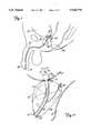
- FIG. 1is a vertical sectional view of a male pelvic region showing the urinary organs affected by benign prostatic hyperplasia.
- FIG. 2is a plan view of the urethral catheter of the present invention.
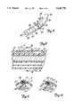
- FIG. 3is a cross-sectional view of the urethral catheter of FIG. 2 taken along line 3--3.
- FIG. 4is a cross-sectional view of the urethral catheter of FIG. 2 taken along line 4--4.
- FIG. 5is a perspective view of a proximal portion of the urethral catheter with the proximal end portion taken in section from line 5--5 of FIG. 2.
- FIG. 6is a perspective view of a combined tip and balloon of the urethral catheter of the present invention.
- FIG. 7is an enlarged sectional view of the proximal end of the urethral catheter of the present invention.
- FIG. 8is a partial sectional view of the temperature sensing lumen and an elongate insert of the urethral catheter of the present invention.
- FIG. 9is a cross-sectional view of the urethral catheter of FIG. 8 taken along line 9--9.
- FIG. 10is a cross-sectional view of an alternative embodiment of a tubular elongate insert of the present invention.
- FIG. 11is an enlarged view of the male pelvic region of FIG. 1 showing the urethral catheter of the present invention positioned within the prostate region.
- FIG. 1is a vertical sectional view of a male pelvic region showing the effect benign prostatic hyperplasia (BPH) has on the urinary organs.
- Urethra 10is a duct leading from bladder 12, through prostate 14 and out orifice 16 of penis end 18. Benign tumorous tissue growth within prostate 14 around urethra 10 causes constriction 20 of urethra 10, which interrupts the flow of urine from bladder 12 to orifice 16.
- the tumorous tissue of prostate 14 which encroaches urethra 10 and causes constriction 20can be effectively removed by heating and necrosing the encroaching tumorous tissue.
- periurethral tumorous tissue of prostate 14 anterior and lateral to urethra 10is heated and necrosed to avoid unnecessary and undesirous damage to urethra 10 and to adjacent healthy tissues, such as ejaculatory duct 24 and rectum 26.
- a selective heating of benign tumorous tissue of prostate 14is made possible by microwave antenna-containing catheter 28 of the present invention, which is shown in FIG. 2.
- catheter 28generally includes multi-port manifold 30, multi-lumen shaft 32, and tip 34 which includes balloon portion 36, tip portion 38, and side port 39.
- Manifold 30includes inflation port 40, urine drainage port 42, microwave antenna port 44, cooling fluid intake port 46, and cooling fluid exhaust port 48. Ports 40-48 of manifold 30 communicate with corresponding lumens within shaft 32.
- Manifold 30is preferably made of medical-grade silicone sold by Dow Corning under the trademark Silastic® Q-7-4850.
- Catheter 28can be employed in a thermal therapy catheter system further including a cooling system, a microwave generating source, and a urethral thermometry unit.
- a thermal therapy catheter systemfurther including a cooling system, a microwave generating source, and a urethral thermometry unit.
- manifold 30 of catheter 28 of the present inventioncooperates with a transurethral thermal catheter system in the same manner that manifold 30 disclosed in the Rudie patent cooperates with the multi-lumen catheter, cooling system, microwave generating source, and transurethral thermometry unit disclosed in that patent.
- inflation port 40 of manifold 30 of the present inventionis adapted for receiving an inflation fluid for inflating balloon 36.
- Urinary drainage port 42 of manifold 30is adapted to facilitate urine from catheter shaft 32, and antenna port 44 is adapted to receive a microwave antenna for insertion and positioning within the multi-lumen catheter shaft 32.
- Cooling fluid intake port 46 and cooling fluid exhaust port 48are cooperable with a cooling system for providing selective flow of cooling fluids within multi-lumen catheter shaft 32.
- Shaft 32is connected to manifold 30 at shaft distal end 50. Shaft 32 is long enough to permit insertion of balloon 36 through urethra 10 and into bladder 12. Shaft 32 is a multi-lumen urethral catheter shaft which is extruded from a flexible, medical-grade silicone sold by Dow Corning under the trademark Silastic® Q-7-4850. The silicone material preferably has a durometer hardness of 80 Shore A.
- multi-lumen shaft 32includes temperature sensing lumen 56, microwave antenna lumen 58, urine drainage lumen 60, balloon inflation lumen 62, cooling fluid intake lumens 64A and 64B, and cooling exhaust lumens 66A and 66B.
- Lumens 56-66Bgenerally extend from distal shaft end 50 to proximal shaft end 54.
- Lumens 56-66Bare defined by unitary wall 68 which has a substantially uniform thickness throughout a cross section of catheter shaft 32.
- Catheter wall 68preferably has a thickness of 0.009 inches.
- a center of each of lumens 56-62is aligned along a longitudinal axis of an elliptical cross section of catheter shaft 32.
- Protective sheath 71covers outer surface 52 of catheter shaft 32 and is preferably made of Teflon® to facilitate its advancement within urethra 10.
- Temperature sensing lumen 56is positioned near first side 70 of shaft 32. Temperature sensing lumen 56 has a generally circular cross sectional surface area and is configured to permit insertion of a thermometry sensor within shaft 32 to monitor the temperature of surrounding prostatic tissue when shaft 32 is inserted within urethra 10. Temperature sensing lumen 56 preferably has a diameter of about 0.032 inches.
- First modified portion 72 of catheter wall 68defines a common wall between antenna lumen 58 and temperature sensing lumen 56.
- First modified wall portion 72preferably has a thickness (e.g., 0.020 inches) about two times the otherwise substantially uniform thickness of catheter wall 68.
- Second modified portion 74 of catheter wall 68defines an outer wall of temperature sensing lumen 56 and preferably has a thickness (e.g., 0.005 inches) about one-half the otherwise substantially uniform wall thickness of catheter wall 68.
- Microwave antenna lumen 58is positioned eccentric to the longitudinal axis of catheter shaft 32, antenna lumen 58 being positioned nearer first side 70 of shaft 32 than second side 76 of shaft 32.
- Microwave antenna lumen 58preferably has a generally circular cross-sectional surface area which is larger than a cross-sectional surface area of any of the other respective lumens of catheter shaft 32.
- Antenna lumen 58preferably has a diameter of about 0.106 inches.
- antenna lumen 58communicates with microwave antenna port 44 of manifold 30.
- Antenna lumen 58is adapted for receiving a microwave antenna to be permanently positioned within antenna lumen 58 of shaft 32 near balloon 36 (FIG.
- a microwave antenna suitable for incorporation into catheter 28 of the present inventionis disclosed in Rudie et al. U.S. Pat. No. 5,413,588, issued May 9, 1995, and is hereby incorporated by reference.
- Urine drainage lumen 60is positioned adjacent antenna lumen 58 between antenna lumen 58 and second side 76 of shaft 32.
- Urine drainage lumen 60has a generally circular cross-sectional surface area defined by catheter wall 68 and preferably has a diameter of about 0.04 inches.
- Urine drainage lumen 60communicates with urine drainage port 42 of manifold 30 at distal shaft end 50 and with tip 34 at proximal shaft end 54 to define a drainage path for urine when tip 34 of catheter 28 is inserted within bladder 12.
- Urineflows into tip 34 through side port 39 (FIG. 2). Drainage of urine from bladder 12 is necessary due to frequent bladder spasms which occur during transurethral thermal therapy.
- Balloon inflation lumen 62is positioned near second side 76 of shaft 32, generally between urine drainage lumen 60 and second side 76.
- Balloon inflation lumen 62preferably has a generally circular cross-sectional surface area defined by catheter wall 68 and preferably has a diameter of about 0.04 inches.
- Balloon inflation lumen 62communicates with inflation port 40 of manifold 30 for moving balloon inflation fluid in and out of the balloon inflation lumen 62.
- Balloon inflation lumen 62is provided for supplying an inflation fluid to balloon portion 36 of tip 34.
- Cooling fluid intake lumens 64A and 64Bare positioned circumjacent antenna lumen 58 and first side 70, being located between first side 70 and antenna lumen 58. Cooling fluid intake lumens 64A and 64B are defined by single unitary catheter wall 68 and preferably have a generally arc shaped cross-sectional surface area configured to partially surround antenna lumen 58. Cooling lumens 64A and 64B also preferably have a uniform radial thickness. Cooling fluid intake lumens 64A and 64B extend from distal shaft end 50 to proximal shaft end 54.
- Fluid contained within intake lumens 64A and 64Babsorbs a portion of microwave energy emitted by a microwave antenna within antenna lumen 58 to control the volume of prostatic tissue adjacent first side 70 of shaft 32 that is heated above 45° C. Water within intake lumens 64A and 64B also absorbs heat energy generated by microwave energy from adjacent tissues via thermal conduction. Cooling fluid intake lumens 64A, 64B have a radial thickness of about 0.028 inches and have an inner radius of 0.062 inches and an outer radius of 0.09 inches (relative to a focus of the elliptical cross-section of shaft 32 nearest first side 70).
- Cooling fluid exhaust lumens 66A and 66Bare generally positioned between second side 76 and antenna lumen 58 and have a generally arc-shaped cross-sectional surface area. First portions 67A and 67B of cooling exhaust lumens 66A and 66B are circumjacent antenna lumen 58 and second portions 69A and 69B are circumjacent second side 76 of catheter shaft 32.
- the generally arc shaped cross-sectional surface area of cooling fluid exhaust lumens 66A and 66Bis modified to accommodate the presence of urine drainage lumen 60 between cooling exhaust lumens 66A and 66B. Cooling exhaust lumens 66A and 66B extend from shaft distal end 50 to shaft proximal end 54.
- Cooling exhaust lumens 66A and 66Bare wider in cross section than cooling intake lumens 64A and 64B and have a cross-sectional surface area greater than the cross-sectional surface area of cooling intake lumens 64A and 64B.
- Cooling fluid exhaust lumens 66A, 66Bhave an outer radius of 0.09 inches (relative to a focus of the elliptical shaft cross section of shaft 32 nearest first side 70).
- Portion 67A, 67B of lumens 66A, 66Bhave an inner radius of 0.062 inches (relative to the focus of the elliptical shaft cross section nearest first side 70).
- exhaust lumens 66A and 66Benable water within exhaust lumen 66A and 66B to be capable of absorbing a greater amount of microwave energy when a microwave antenna disposed within antenna lumen 58 is energized.
- the temperature of tissue adjacent second side 76 of shaft 32will remain below about 45° C. This prevents the portion of urethra 10 adjacent second side 76 from being overheated and damaged when a microwave antenna within antenna lumen 58 is energized.
- Cooling intake lumens 64A and 64B and exhaust lumens 66A and 66Bcooperate with a cooling system via ports 46 and 48 of manifold 30 to provide a selectively controlled flow of fluid through cooling lumens 64A, 64B, 66A, and 66B during a treatment session.
- This arrangementachieves a desired cooling pattern surrounding a microwave antenna energized within antenna lumen 58 while catheter shaft 32 is within a urethra 10.
- Cooling intake lumens 64A, 64B and cooling exhaust lumens 66A, 66Bcan be used with a cooling system under the treatment parameters as described in Rudie et al. U.S. Pat. No. 5,413,588, (earlier incorporated by reference) and under the treatment parameters disclosed in pending application U.S. Ser. No. 08/309,137, filed Sep. 20, 1994.
- Cooling fluid intake lumens 64A and 64Bare in communication with cooling exhaust lumens 66A and 66B, respectively, near proximal shaft end 54 of catheter shaft 32 adjacent balloon portion 36 (FIG. 2). As shown in FIG. 4, a portion of catheter wall 68 defining a common wall between cooling intake lumen 64A and cooling exhaust lumen 66A has been removed creating hole 77A to permit communication between the respective lumens. Similarly, a portion of catheter wall 68 defining a common wall between cooling intake lumen 64B and cooling exhaust lumen 66B has been removed creating hole 77B to allow communication between the respective lumens 64B and 66B. This configuration permits cooling fluid that is flowing proximally through cooling intake lumens 64A and 64B to enter cooling exhaust lumens 66A and 66B, respectively, to establish a cooling fluid flow loop that cooperates with a cooling system connected to manifold 30.
- FIG. 5illustrates a cross section of catheter shaft 32 adjacent a shaft end 54 just proximal to balloon 36 (see FIG. 2).
- temperature sensing lumen 56, antenna lumen 58, inflation lumen 62, cooling intake lumens 64A and 64B, and cooling exhaust lumens 66A and 66Bare closed by silicone plug material 78 sealing each of these lumens at proximal shaft end 54.
- urine drainage lumen 60remains open at proximal shaft end 54 so that urine from the bladder may pass through tip 34 and into urine drainage lumen 60.
- tip 34comprises a single unitary member including balloon portion 36 and tip portion 38.
- Balloon portion 36is a flexible tubular portion having distal end 80, proximal end 82, side wall 84, inner surface 86, ribs 88, and hole 90.
- Side wall 84 of tubular balloon portion 36extends between distal end 80 and proximal end 82 and has inner surface 86 with ribs 88 formed thereon extending circumferentially on the inner surface 86. Ribs 88 are visible in FIG. 6 since flexible tubular portion of balloon portion 36 is preferably made from a translucent material.
- Side wall 84 of tubular balloon portion 36includes hole 90 formed adjacent proximal end 82.
- Tip portion 38comprises a flexible curved body having distal end 92, proximal tip end 94, tip lumen 96, dividing wall 98, and hole 100.
- Tip lumen 96extends through a portion of the tip body and communicates with side port 39.
- Side port 39permits insertion of a guide wire (not shown) into tip lumen 96 to facilitate insertion of intraurethral catheter 28 within urethra 10 in a manner well known in the art.
- Dividing wall 98 at distal end 92defines a border between balloon portion 36 and tip portion 38.
- Wall 98also defines a distal end of tip lumen 96 and has hole 100 formed therein to permit communication between tip lumen 96 and an interior of tubular balloon portion 36.
- Tip 34is formed by liquid injection molding from a flexible, medical-grade silicone sold by Dow Corning under the trademark Silastic® Q-7-4850.
- the siliconepreferably has a material hardness of 20 Shore A, which is relatively soft to provide an atraumatic tip.
- Tip 34can also include a radiopaque filler such as barium sulfate added to the silicone material to make tip 34 observable under fluoroscopy.
- Tip 34preferably has a length of 1.95 inches including tip portion 38 which preferably has a length of 0.84 inches.
- Tubular portion 36preferably has a length of 1.11 inches including the ribbed portion which has a length of 0.64 inches.
- Side wall 94preferably has a thickness of 0.01 inches while ribs 88 preferably have a radius of 0.01 inches and are spaced longitudinally with respect to each other by 0.16 inches.
- Tubular portion 36has an elliptical cross section and has a radius of about 0.110 inches, wherein the foci of the ellipse are separated by 0.053 inches.
- Side wall 94 of tubular portionis capable of elongating up to 400% so that an elliptical cross section of balloon portion 36 when expanded has a cross sectional area about 4 times its cross sectional area in a nonexpanded state.
- FIG. 7provides a more detailed view of catheter shaft 32 and tip 34 at proximal shaft end 54.
- Proximal shaft end 54 of catheter 28fits snugly within tubular portion 36 of tip 34 with utmost proximal shaft end 54 resting against dividing wall 98 of tip 34 and outer surface 52 of catheter shaft 32 in contact with multiple structures defining an interior of tubular balloon portion 36.
- urine drainage lumen 60further includes expanded diameter portion 102 while inflation lumen 62 further includes hole 104.
- Temperature sensing lumen 56, antenna lumen 58, and inflation lumen 62further include silicone plug material 78 filled within their proximal ends.
- Balloon portion 36 of tip 34further includes first collar 106, second collar 108, first well 110, second well 112, third well 114, adhesive dam 116, first rib 118, and second rib 119.
- Expanded diameter section 102 of urine drainage lumen 60has a generally conical shape and communicates with tip lumen 96 via hole 100 in wall 98 to permit urine flow therethrough.
- Hole 104 of inflation lumen 62permits communication between inflation lumen 62 and an interior of balloon portion 36 for inflating and deflating balloon portion 36.
- Expanded diameter portion 102 of urine drainage lumen 60is formed at the time silicone plug material 78 is introduced into the other lumens 32 at proximal shaft end 54.
- a syringe tipis introduced into urine drainage lumen 60 at proximal shaft end 54 and maintained in that position while silicone plug material 78 is introduced into all of the remaining lumens defining catheter shaft 32.
- the introduction of silicone plug material 78includes the application of heat to proximal shaft end 54, thereby causing urinary drainage lumen 60 to permanently expand and reform about the shape of the syringe tip.
- the syringe tipUpon setting of the silicone plug material 78, the syringe tip is removed from proximal shaft end 54 resulting in urine drainage lumen 60 having expanded diameter portion 102 and each of the other respective lumens of catheter shaft 32 having sealed ends filled with silicone plug material 78.
- First collar 106 of balloon portion 36defines distal end 80 while second collar 108 defines proximal end 82 with side wall 84 extending therebetween.
- First well 110defines a reservoir formed between first collar 106, first rib 118, and side wall 84 while second well 112 defines a reservoir formed between second collar 108, side wall 84, and adhesive dam 116.
- Third well 114defines a reservoir formed between adhesive dam 116, side wall 84, and second rib 119.
- tubular portion 36is slip fit over proximal shaft end 54 into the position shown in FIG. 7.
- tubular portion 36is secured about proximal shaft end 54 with an adhesive.
- Adhesiveis introduced between first collar 106 and shaft outer surface 52 of shaft 32 to create a sealed connection therebetween.
- First well 110catches any excess adhesive that wicks proximally beyond first collar 106.
- Side hole 90is used to introduce adhesive between second collar 108 and shaft outer surface 32 at utmost shaft proximal end 54.
- Second well 112receives adhesive introduced through side hole 90 while adhesive dam 116 blocks adhesive from migrating distally toward inner surface 86 of side wall 84.
- Third well 118acts as an additional reservoir for catching excess adhesive migrating past adhesive dam 116.
- first collar 106 and second collar 108 of tubular portion 36sealingly connected about shaft outer surface 52, side wall 84 remains free to expand relative to shaft outer surface 52 upon introduction of inflation fluid within an interior of balloon portion 36 (via inflation lumen 62 through hole 104).
- Ribs 88remain spaced slightly from outer surface 52 and maintain spacing between inner surface 86 of side wall 84 and outer surface 52 of catheter shaft 32. This prevents the silicone material forming balloon portion 36 from sticking to the silicone material forming shaft outer surface 52. In the absence of ribs 88, inner surface 86 of side wall 84 would tend to stick to shaft outer surface 52 and thereby inhibit inflation and expansion of side wall 84.
- Tubular portion 36is positioned on proximal shaft end 54 so that side wall 84 can be expanded within bladder 12 to maintain a proximal end of a microwave antenna (within catheter shaft 32) spaced at least 4 millimeters proximally from the opening of the bladder 12. This positions the microwave antenna within urethra 10 so that healthy prostatic tissue between a tip of the microwave antenna and bladder 12 is preserved.
- an alternative embodiment of catheter shaft 32further includes elongate insert 120.
- Elongate insert 120includes first end 122 and second end 124.
- Elongate insert 120is positioned within temperature sensing lumen 56 alongside sensor 126 of thermal sensing device 128 adjacent microwave antenna 130 positioned within antenna lumen 58.
- Elongate insert 120displaces sensor 126 of thermal sensing device 128 radially away from antenna 130 and toward first side 70 of catheter shaft 32.
- FIG. 9illustrates a cross-sectional view of elongate insert 120.
- Elongate insert 120has a generally crescent shaped cross-sectional surface area including a concave surface and has a width approximately one-half the diameter of temperature sensing lumen 56.
- Concave surface 127 of elongate insert 120is positioned circumjacent sensor 126 between thermal sensing device 128 and antenna lumen 58 to move sensor 126 within temperature sensing lumen 56 as far away as possible from microwave antenna 130 and cooling lumens 64A and 64B.
- This arrangementincreases the accuracy of temperature measurements of surrounding prostatic tissue adjacent shaft first side 70 by better insulating sensor 126 from both heating (microwave antenna) and cooling (cooling fluid) sources within catheter shaft 32.
- Elongate insert 120in filling up a portion of the cross sectional area within temperature sensing lumen 56, effectively eliminates excess spacing within lumen 56 that is necessary to permit insertion of thermal sensing device 128 within lumen 56.
- Elongate insert 120can be inserted into temperature sensing lumen 56 either before or after thermal sensing device 128 is positioned within temperature sensing lumen 56.
- Elongate insert 120is introduced into temperature sensing lumen 56 by making a cut in first side 70 of catheter shaft 32 adjacent temperature sensing lumen 56 and advancing elongate insert 120 distally through temperature sensing lumen 56 until elongate insert 120 is completely within temperature sensing 56 and resting on an inner wall of temperature sensing lumen 56.
- Elongate insert 120is then held in place against the inner wall of temperature sensing lumen 56 until sensor 126 is properly positioned relative to elongate insert 120. Thereafter, the slit made in first side 70 of catheter shaft 32 is sealed using an adhesive filler.
- Elongate insert 120has a length of about one to two inches, a thickness at its center of about 0.013 inches, and a width between its outer edges of about 0.32 inches.
- Elongate insert 120is preferably formed from a Teflon® material to facilitate sliding movement of sensor 126 relative to insert 120.
- tubular elongate insert 140provides an alternative embodiment to crescent shaped elongate insert 120.
- Tubular elongate insert 140includes inner surface 142, outer surface 144 and wall 146 defined therebetween.
- Tubular insert 140is positioned within temperature sensing lumen 58 and surrounds sensor 126 of thermal sensing device 128.
- tubular insert 140displaces sensor 126 away from antenna 130 and cooling lumens 64A and 64B toward first side 70 of catheter shaft 32, thereby eliminating excess space within temperature sensing lumen 58 and increasing the accuracy of temperature measurements of the surrounding prostatic tissue.
- Tubular insert 140is placed within temperature sensing lumen 58 according to the insertion method described for elongate insert 120.
- Tubular insert 140is preferably formed from a Teflon® material to facilitate sliding movement of sensor 126 relative to tubular insert 140.
- Tubular insert 140has a length of about one to two inches, wall 146 has a uniform radial thickness of about 0.007 inches, and outer surface 144 has a diameter of about 0.032 inches.
- catheter 28 of the present inventionincluding multi-lumen catheter shaft 32 and tip 34 including balloon portion 36 is employed according to the insertion method and treatment method described in Rudie et at. U.S. Pat. No. 5,413,588. Additional urethral treatment parameters can be employed with catheter 28 of the present invention such as that described in U.S. patent application Ser. No. 08/309,137 filed Sep. 20, 1994 and hereby incorporated by reference.
- FIG. 11shows an enlarged view of the male pelvic region of FIG. 1 with catheter 28 properly positioned within urethra 10.
- Shaft 32is positioned within urethra 10 with second side 76 of shaft 32 oriented toward rectum 26.
- Cooling fluid exhaust lumens 66A, 66Bare oriented posteriorly, toward rectum 26 and cooling fluid intake lumens 64A, 64B are oriented anteriorly toward fibromuscular tissue 140 of prostate 14.
- the portion of transition zone 142 anterior and lateral to urethra 10is the most frequent location of the tumorous tissue growth which causes BPH.
- cooling fluid exhaust lumens 66A, 66Bare capable of absorbing more microwave energy than cooling fluid intake lumens 64A, 64B, the radiation patterns created by microwave energy emitted from antenna 144 are asymmetrical.
- a relatively large volume of tissue enveloping the anterior portion of transition zone 142, adjacent first side 70,is heated to a temperature above about 45° C., which effectively necroses the tumorous tissue of prostate 14 which encroaches upon urethra 10.
- the temperature of tissue adjacent second side 76remains below about 45° C., thereby eliminating the harmful effects of the microwave energy to ejaculatory duct 24 and rectum 26.
- Multi lumen catheter shaft 32is configured to maximize exposure of its cooling lumens to an antenna lumen carrying a microwave antenna.
- This optimized configurationis established by having cooling fluid intake and exhaust lumens with a generally arc shaped cross-sectional area which substantially surround an antenna lumen having a generally circular cross-sectional area.
- These lumensare defined by a unitary wall having a substantially uniform wall thickness arranged to maximize the cross-sectional surface area of the cooling lumens relative to the antenna lumen.
- a urine drainage lumen of the present inventionhas a generally circular cross-sectional surface area which tends to remain open even when an intraurethral catheter of the present invention is disposed within a portion of a urethra which bends the intraurethral catheter.
- the generally circular cross-sectional area of the urine drainage lumen disposed adjacent the antenna lumenminimizes the relative surface area and exposure between the urine drainage lumen and the antenna lumen. This reduces the effect that variable urine flow within the urine drainage lumen has on microwave antenna tuning and on the consistency of the shape and energy of a microwave radiation pattern generated by the microwave antenna within the antenna lumen.
- the lumens of multi lumen catheter shaft 32are arranged and shaped to increase the structural integrity of catheter shaft 32 while maximizing the surface area of each of the respective lumens. This is accomplished by defining the respective lumens by a single unitary wall having a substantially uniform wall thickness and by selecting optimal shapes of the cross-sectional surface area of the lumens.
- the tip 34 of catheter 28 of the present inventionalso has numerous advantages.
- a tipcomprising a single unitary member including an insertion tip and an inflatable balloon portion greatly simplifies assembly of the catheter.
- the tipcan simply be slip fit over a proximal end of the catheter shaft and secured thereto with an adhesive.
- the insertion tip portionfacilitates insertion and guidance of the catheter of the present invention within the urethra.
- a balloon of a tip of the present inventionis constructed to maintain a low profile in its deflated state to facilitate insertion and passage of the catheter within a urethra.
- a balloon of a tip of the present inventiondoes not have any excess material or winged portions which must be folded down or compressed during insertion of or passage of the balloon through the urethra. Rather, the unique structure of a balloon of the tip of the present invention yields a balloon which remains relatively flat in its deflated state during passage through the urethra.
- a tubular portion comprising a balloon of the present inventionis arranged and configured to facilitate introducing adhesive for seating the balloon about an outer surface of the catheter shaft without compromising an effective length of the inflatable portion of the balloon caused by wicking of the adhesive toward an anterior portion of the balloon.
Landscapes
- Health & Medical Sciences (AREA)
- Surgery (AREA)
- Life Sciences & Earth Sciences (AREA)
- Medical Informatics (AREA)
- Animal Behavior & Ethology (AREA)
- Nuclear Medicine, Radiotherapy & Molecular Imaging (AREA)
- Electromagnetism (AREA)
- Engineering & Computer Science (AREA)
- Biomedical Technology (AREA)
- Heart & Thoracic Surgery (AREA)
- Physics & Mathematics (AREA)
- Molecular Biology (AREA)
- Otolaryngology (AREA)
- General Health & Medical Sciences (AREA)
- Public Health (AREA)
- Veterinary Medicine (AREA)
- Radiation-Therapy Devices (AREA)
- Thermotherapy And Cooling Therapy Devices (AREA)
- Media Introduction/Drainage Providing Device (AREA)
- Surgical Instruments (AREA)
- Acyclic And Carbocyclic Compounds In Medicinal Compositions (AREA)
Abstract
Description
Claims (20)
Priority Applications (6)
| Application Number | Priority Date | Filing Date | Title |
|---|---|---|---|
| US08/469,201US5628770A (en) | 1995-06-06 | 1995-06-06 | Devices for transurethral thermal therapy |
| JP9500796AJPH11506639A (en) | 1995-06-06 | 1996-05-29 | Instruments for transurethral heat treatment |
| PCT/US1996/007878WO1996039227A1 (en) | 1995-06-06 | 1996-05-29 | Device for transurethral thermal therapy |
| AU59385/96AAU710205B2 (en) | 1995-06-06 | 1996-05-29 | Device for transurethral thermal therapy |
| CA002222202ACA2222202A1 (en) | 1995-06-06 | 1996-05-29 | Device for transurethral thermal therapy |
| EP96916718AEP0837715A1 (en) | 1995-06-06 | 1996-05-29 | Device for transurethral thermal therapy |
Applications Claiming Priority (1)
| Application Number | Priority Date | Filing Date | Title |
|---|---|---|---|
| US08/469,201US5628770A (en) | 1995-06-06 | 1995-06-06 | Devices for transurethral thermal therapy |
Publications (1)
| Publication Number | Publication Date |
|---|---|
| US5628770Atrue US5628770A (en) | 1997-05-13 |
Family
ID=23862862
Family Applications (1)
| Application Number | Title | Priority Date | Filing Date |
|---|---|---|---|
| US08/469,201Expired - LifetimeUS5628770A (en) | 1995-06-06 | 1995-06-06 | Devices for transurethral thermal therapy |
Country Status (6)
| Country | Link |
|---|---|
| US (1) | US5628770A (en) |
| EP (1) | EP0837715A1 (en) |
| JP (1) | JPH11506639A (en) |
| AU (1) | AU710205B2 (en) |
| CA (1) | CA2222202A1 (en) |
| WO (1) | WO1996039227A1 (en) |
Cited By (70)
| Publication number | Priority date | Publication date | Assignee | Title |
|---|---|---|---|---|
| WO1997048450A1 (en)* | 1996-06-17 | 1997-12-24 | Urologix, Inc. | Device for transurethral thermal therapy with cooling balloon |
| US5776176A (en)* | 1996-06-17 | 1998-07-07 | Urologix Inc. | Microwave antenna for arterial for arterial microwave applicator |
| US5861021A (en)* | 1996-06-17 | 1999-01-19 | Urologix Inc | Microwave thermal therapy of cardiac tissue |
| US5987360A (en)* | 1996-05-03 | 1999-11-16 | Urologix, Inc. | Axial preferential thermal therapy |
| US6035238A (en)* | 1997-08-13 | 2000-03-07 | Surx, Inc. | Noninvasive devices, methods, and systems for shrinking of tissues |
| US6081749A (en)* | 1997-08-13 | 2000-06-27 | Surx, Inc. | Noninvasive devices, methods, and systems for shrinking of tissues |
| US6122551A (en)* | 1998-12-11 | 2000-09-19 | Urologix, Inc. | Method of controlling thermal therapy |
| US6213976B1 (en) | 1999-07-22 | 2001-04-10 | Advanced Research And Technology Institute, Inc. | Brachytherapy guide catheter |
| US6272384B1 (en) | 1999-05-27 | 2001-08-07 | Urologix, Inc. | Microwave therapy apparatus |
| US6283987B1 (en) | 1998-01-14 | 2001-09-04 | Surx, Inc. | Ribbed electrodes and methods for their use |
| US6312426B1 (en) | 1997-05-30 | 2001-11-06 | Sherwood Services Ag | Method and system for performing plate type radiofrequency ablation |
| US6319229B1 (en)* | 1998-02-19 | 2001-11-20 | Medtronic Percusurge, Inc. | Balloon catheter and method of manufacture |
| US6440127B2 (en) | 1998-02-11 | 2002-08-27 | Cosman Company, Inc. | Method for performing intraurethral radio-frequency urethral enlargement |
| US6447505B2 (en) | 1998-02-11 | 2002-09-10 | Cosman Company, Inc. | Balloon catheter method for intra-urethral radio-frequency urethral enlargement |
| US6480746B1 (en) | 1997-08-13 | 2002-11-12 | Surx, Inc. | Noninvasive devices, methods, and systems for shrinking of tissues |
| US6517534B1 (en) | 1998-02-11 | 2003-02-11 | Cosman Company, Inc. | Peri-urethral ablation |
| US6546934B1 (en) | 1996-11-08 | 2003-04-15 | Surx, Inc. | Noninvasive devices and methods for shrinking of tissues |
| US6599237B1 (en) | 2000-01-10 | 2003-07-29 | Errol O. Singh | Instrument and method for facilitating endoscopic examination and surgical procedures |
| US20030178032A1 (en)* | 1997-08-13 | 2003-09-25 | Surx, Inc. | Noninvasive devices, methods, and systems for shrinking of tissues |
| US6695787B2 (en) | 2000-08-25 | 2004-02-24 | Neoseed Technology Llc. | Prostate visualization device and methods of use |
| US6743226B2 (en) | 2001-02-09 | 2004-06-01 | Cosman Company, Inc. | Adjustable trans-urethral radio-frequency ablation |
| US6751507B2 (en) | 1999-09-10 | 2004-06-15 | Solarant Medical, Inc. | Endopelvic fascia treatment for incontinence |
| US20040267336A1 (en)* | 1996-11-08 | 2004-12-30 | Solarant Medical, Inc. | Energy induced bulking and buttressing of tissues for incontinence |
| US20050148999A1 (en)* | 2003-12-30 | 2005-07-07 | Opmi Funding, Inc. | Continuous drainage adaptor |
| US20060147245A1 (en)* | 2004-12-30 | 2006-07-06 | Carl Cetera | Implement grip |
| US20060167533A1 (en)* | 2005-01-21 | 2006-07-27 | Solarant Medical, Inc. | Endo-pelvic fascia penetrating heating systems and methods for incontinence treatment |
| US20060282069A1 (en)* | 2001-11-02 | 2006-12-14 | Mani Prakash | High-strength microwave antenna assemblies and methods of use |
| US20070005049A1 (en)* | 2005-06-30 | 2007-01-04 | Comben Richard H | Apparatus and Method of Treating Urinary Incontinence by Heating Urethra |
| US20070093880A1 (en)* | 2005-10-06 | 2007-04-26 | Boston Scientific Scimed, Inc. | Adjustable profile probe |
| US20080135217A1 (en)* | 2003-07-18 | 2008-06-12 | Roman Turovskiy | Devices and Methods for Cooling Microwave Antennas |
| US20080275436A1 (en)* | 2004-07-02 | 2008-11-06 | Nigel Cronin | Radiation Applicator and Method of Radiating Tissue |
| US20080294162A1 (en)* | 2007-05-22 | 2008-11-27 | Francesca Rossetto | Energy delivery conduits for use with electrosugical devices |
| US20090005766A1 (en)* | 2007-06-28 | 2009-01-01 | Joseph Brannan | Broadband microwave applicator |
| US20090187180A1 (en)* | 2008-01-23 | 2009-07-23 | Vivant Medical, Inc. | Choked Dielectric Loaded Tip Dipole Microwave Antenna |
| US20090221992A1 (en)* | 2008-02-28 | 2009-09-03 | Hollister Incorporated | Fluid Drainage Catheter Having an External Flow Path |
| US20090318798A1 (en)* | 2008-06-23 | 2009-12-24 | Errol Singh | Flexible visually directed medical intubation instrument and method |
| US20090318757A1 (en)* | 2008-06-23 | 2009-12-24 | Percuvision, Llc | Flexible visually directed medical intubation instrument and method |
| US20100053015A1 (en)* | 2008-08-28 | 2010-03-04 | Vivant Medical, Inc. | Microwave Antenna |
| US7799019B2 (en) | 2005-05-10 | 2010-09-21 | Vivant Medical, Inc. | Reinforced high strength microwave antenna |
| US20100286679A1 (en)* | 2009-04-27 | 2010-11-11 | Michael Hoey | Systems and Methods for Prostate Treatment |
| US7998139B2 (en) | 2007-04-25 | 2011-08-16 | Vivant Medical, Inc. | Cooled helical antenna for microwave ablation |
| US20130090640A1 (en)* | 2011-10-07 | 2013-04-11 | University Of Surrey | Methods and systems for detection and thermal treatment of lower urinary tract conditions |
| US20130144286A1 (en)* | 2010-05-17 | 2013-06-06 | Consiglio Nazionale Delle Ricerche | Microwave surgical device |
| US8651146B2 (en) | 2007-09-28 | 2014-02-18 | Covidien Lp | Cable stand-off |
| US8968284B2 (en) | 2000-10-02 | 2015-03-03 | Verathon Inc. | Apparatus and methods for treating female urinary incontinence |
| US9023031B2 (en) | 1997-08-13 | 2015-05-05 | Verathon Inc. | Noninvasive devices, methods, and systems for modifying tissues |
| US9023024B2 (en) | 2007-06-20 | 2015-05-05 | Covidien Lp | Reflective power monitoring for microwave applications |
| WO2015114560A1 (en)* | 2014-01-29 | 2015-08-06 | Baylis Medical Company Inc. | Side-port catheter |
| US9198708B2 (en) | 2010-03-25 | 2015-12-01 | Nxthera, Inc. | Systems and methods for prostate treatment |
| US9345507B2 (en) | 2008-11-06 | 2016-05-24 | Nxthera, Inc. | Systems and methods for treatment of BPH |
| US20160184551A1 (en)* | 2014-12-29 | 2016-06-30 | Dentsply International Inc. | Urinary catheter having a soft tip |
| US9549779B2 (en) | 2001-11-02 | 2017-01-24 | Covidien Lp | High-strength microwave antenna assemblies |
| US9895185B2 (en) | 2011-09-13 | 2018-02-20 | Nxthera, Inc. | Systems and methods for prostate treatment |
| US9968395B2 (en) | 2013-12-10 | 2018-05-15 | Nxthera, Inc. | Systems and methods for treating the prostate |
| US10085694B2 (en) | 2011-07-15 | 2018-10-02 | Boston Scientific Scimed, Inc. | Systems and methods for monitoring organ activity |
| US10194970B2 (en) | 2013-12-10 | 2019-02-05 | Nxthera, Inc. | Vapor ablation systems and methods |
| US10335222B2 (en) | 2012-04-03 | 2019-07-02 | Nxthera, Inc. | Induction coil vapor generator |
| US10342593B2 (en) | 2015-01-29 | 2019-07-09 | Nxthera, Inc. | Vapor ablation systems and methods |
| US10610281B2 (en) | 2008-11-06 | 2020-04-07 | Boston Scientific Scimed, Inc. | Systems and methods for treatment of prostatic tissue |
| US10675435B2 (en) | 2015-04-01 | 2020-06-09 | Spinal Singularity, Inc. | Extended-use valved urinary catheter |
| US10675134B2 (en) | 2015-01-23 | 2020-06-09 | Spinal Singularity, Inc. | Bladder management systems |
| US10702327B2 (en) | 2015-05-13 | 2020-07-07 | Boston Scientific Scimed, Inc. | Systems and methods for treating the bladder with condensable vapor |
| US10751107B2 (en) | 2017-01-06 | 2020-08-25 | Boston Scientific Scimed, Inc. | Transperineal vapor ablation systems and methods |
| US10751506B2 (en) | 2015-04-01 | 2020-08-25 | Spinal Singularity, Inc. | Catheters and catheter mating devices and systems |
| US10772670B2 (en) | 2013-03-14 | 2020-09-15 | Boston Scientific Scimed, Inc. | Systems and methods for treating prostate cancer |
| US11065093B2 (en) | 2015-01-23 | 2021-07-20 | Spinal Singularity, Inc. | Catheter mating devices |
| US11246640B2 (en) | 2016-12-21 | 2022-02-15 | Boston Scientific Scimed, Inc. | Vapor ablation systems and methods |
| US11510765B2 (en)* | 2015-01-23 | 2022-11-29 | Spinal Singularity, Inc. | Extended-use catheters |
| US11628271B2 (en) | 2019-06-10 | 2023-04-18 | Spinal Singularity, Inc. | Urinary catheter |
| US12440258B2 (en) | 2023-11-20 | 2025-10-14 | Boston Scientific Scimed, Inc. | Systems and methods for treating prostate cancer |
Families Citing this family (7)
| Publication number | Priority date | Publication date | Assignee | Title |
|---|---|---|---|---|
| US5843144A (en)* | 1995-06-26 | 1998-12-01 | Urologix, Inc. | Method for treating benign prostatic hyperplasia with thermal therapy |
| AU6329498A (en) | 1997-02-13 | 1998-09-08 | Boston Scientific Ireland Limited, Barbados Head Office | Percutaneous and hiatal devices and methods for use in minimally invasive pelvicsurgery |
| EP1665991B1 (en) | 2000-06-05 | 2017-12-13 | Boston Scientific Limited | Devices for the treatment of urinary continence |
| US7364541B2 (en) | 2001-03-09 | 2008-04-29 | Boston Scientific Scimed, Inc. | Systems, methods and devices relating to delivery of medical implants |
| US9149261B2 (en) | 2001-03-09 | 2015-10-06 | Boston Scientific Scimed, Inc. | Systems, methods and devices relating to delivery of medical implants |
| US8915927B2 (en) | 2001-03-09 | 2014-12-23 | Boston Scientific Scimed, Inc. | Systems, methods and devices relating to delivery of medical implants |
| ITMI20081857A1 (en)* | 2008-10-20 | 2010-04-21 | Francesco Rocco | CATHETER STRUCTURE. |
Citations (74)
| Publication number | Priority date | Publication date | Assignee | Title |
|---|---|---|---|---|
| US550238A (en)* | 1895-11-26 | Horace russel allen | ||
| US2642874A (en)* | 1951-06-04 | 1953-06-23 | Wilmer B Keeling | Instrument for treating prostate glands |
| US2936761A (en)* | 1958-04-25 | 1960-05-17 | Snyder Henry Howard | Catheter |
| US3125096A (en)* | 1964-03-17 | Compressor | ||
| US3228400A (en)* | 1962-12-03 | 1966-01-11 | Thomas A Armao | Cryogenic capsule probes |
| US3812841A (en)* | 1972-08-21 | 1974-05-28 | L Isaacson | Urethra magnetic valve structure |
| US4140130A (en)* | 1977-05-31 | 1979-02-20 | Storm Iii Frederick K | Electrode structure for radio frequency localized heating of tumor bearing tissue |
| US4162500A (en)* | 1977-10-14 | 1979-07-24 | The United States Of America As Represented By The Secretary Of The Army | Ridged waveguide antenna submerged in dielectric liquid |
| US4204549A (en)* | 1977-12-12 | 1980-05-27 | Rca Corporation | Coaxial applicator for microwave hyperthermia |
| US4224929A (en)* | 1977-11-08 | 1980-09-30 | Olympus Optical Co., Ltd. | Endoscope with expansible cuff member and operation section |
| US4311154A (en)* | 1979-03-23 | 1982-01-19 | Rca Corporation | Nonsymmetrical bulb applicator for hyperthermic treatment of the body |
| US4375220A (en)* | 1980-05-09 | 1983-03-01 | Matvias Fredrick M | Microwave applicator with cooling mechanism for intracavitary treatment of cancer |
| JPS5870219A (en)* | 1981-07-13 | 1983-04-26 | イーストマン コダック カンパニー | Automatic winder/unwider camera |
| US4423725A (en)* | 1982-03-31 | 1984-01-03 | Baran Ostap E | Multiple surgical cuff |
| US4445892A (en)* | 1982-05-06 | 1984-05-01 | Laserscope, Inc. | Dual balloon catheter device |
| US4453545A (en)* | 1981-05-07 | 1984-06-12 | Hiroshi Inoue | Endotracheal tube with movable endobronchial blocker for one-lung anesthesia |
| US4497324A (en)* | 1983-10-03 | 1985-02-05 | American Hospital Supply Corporation | Temperature monitoring catheter |
| US4557272A (en)* | 1980-03-31 | 1985-12-10 | Microwave Associates, Inc. | Microwave endoscope detection and treatment system |
| US4559951A (en)* | 1982-11-29 | 1985-12-24 | Cardiac Pacemakers, Inc. | Catheter assembly |
| US4573966A (en)* | 1981-11-24 | 1986-03-04 | Schneider Medintag Ag | Method and apparatus for removing and/or enlarging constricted areas in vessels conducting body fluids |
| US4583556A (en)* | 1982-12-13 | 1986-04-22 | M/A-Com, Inc. | Microwave applicator/receiver apparatus |
| US4601296A (en)* | 1983-10-07 | 1986-07-22 | Yeda Research And Development Co., Ltd. | Hyperthermia apparatus |
| US4632127A (en)* | 1985-06-17 | 1986-12-30 | Rca Corporation | Scanning microwave hyperthermia with feedback temperature control |
| US4643186A (en)* | 1985-10-30 | 1987-02-17 | Rca Corporation | Percutaneous transluminal microwave catheter angioplasty |
| US4655746A (en)* | 1985-12-02 | 1987-04-07 | Target Therapeutics | Catheter device |
| US4662383A (en)* | 1982-09-27 | 1987-05-05 | Kureha Kagaku Kogyo Kabushiki Kaisha | Endotract antenna device for hyperthermia |
| US4676258A (en)* | 1983-01-24 | 1987-06-30 | Kureha Kagaku Kogyo Kabushiki Kaisha | Device for hyperthermia |
| US4681122A (en)* | 1985-09-23 | 1987-07-21 | Victory Engineering Corp. | Stereotaxic catheter for microwave thermotherapy |
| US4700716A (en)* | 1986-02-27 | 1987-10-20 | Kasevich Associates, Inc. | Collinear antenna array applicator |
| US4708718A (en)* | 1985-07-02 | 1987-11-24 | Target Therapeutics | Hyperthermic treatment of tumors |
| US4709698A (en)* | 1986-05-14 | 1987-12-01 | Thomas J. Fogarty | Heatable dilation catheter |
| US4753238A (en)* | 1987-01-06 | 1988-06-28 | Advanced Cardiovascular Systems, Inc. | Proximal manifold and adapter |
| JPS63177867A (en)* | 1987-01-16 | 1988-07-22 | オリンパス光学工業株式会社 | Balloon device of body cavity remedy device |
| US4763654A (en)* | 1986-09-10 | 1988-08-16 | Jang G David | Tandem independently inflatable/deflatable multiple diameter balloon angioplasty catheter systems and method of use |
| US4771777A (en)* | 1987-01-06 | 1988-09-20 | Advanced Cardiovascular Systems, Inc. | Perfusion type balloon dilatation catheter, apparatus and method |
| US4777951A (en)* | 1986-09-19 | 1988-10-18 | Mansfield Scientific, Inc. | Procedure and catheter instrument for treating patients for aortic stenosis |
| US4800899A (en)* | 1984-10-22 | 1989-01-31 | Microthermia Technology, Inc. | Apparatus for destroying cells in tumors and the like |
| US4813429A (en)* | 1986-05-12 | 1989-03-21 | Biodan Medical Systems Ltd. | Catheter and probe |
| US4824436A (en)* | 1985-04-09 | 1989-04-25 | Harvey Wolinsky | Method for the prevention of restenosis |
| US4832023A (en)* | 1987-06-03 | 1989-05-23 | Mcm Laboratories, Inc. | Method and apparatus for reducing blockage in body channels |
| US4878492A (en)* | 1987-10-08 | 1989-11-07 | C. R. Bard, Inc. | Laser balloon catheter |
| US4911163A (en)* | 1986-06-12 | 1990-03-27 | Ernesto Fina | Two ballooned catheter device for diagnostic and operative use |
| US4921483A (en)* | 1985-12-19 | 1990-05-01 | Leocor, Inc. | Angioplasty catheter |
| US4924863A (en)* | 1988-05-04 | 1990-05-15 | Mmtc, Inc. | Angioplastic method for removing plaque from a vas |
| US4932958A (en)* | 1988-05-10 | 1990-06-12 | American Medical Systems, Inc. | Prostate balloon dilator |
| US4946449A (en)* | 1986-12-18 | 1990-08-07 | Davis Jr Richard C | Indwelling urethral catheter system and method |
| US4955377A (en)* | 1988-10-28 | 1990-09-11 | Lennox Charles D | Device and method for heating tissue in a patient's body |
| US4961738A (en)* | 1987-01-28 | 1990-10-09 | Mackin Robert A | Angioplasty catheter with illumination and visualization within angioplasty balloon |
| US4967765A (en)* | 1988-07-28 | 1990-11-06 | Bsd Medical Corporation | Urethral inserted applicator for prostate hyperthermia |
| US4993430A (en)* | 1987-01-06 | 1991-02-19 | Omron Tateisi Electronics Co. | Electrode device for high frequency thermotherapy apparatus |
| US4998933A (en)* | 1988-06-10 | 1991-03-12 | Advanced Angioplasty Products, Inc. | Thermal angioplasty catheter and method |
| US5002531A (en)* | 1986-06-26 | 1991-03-26 | Tassilo Bonzel | Dilation catheter with an inflatable balloon |
| US5002532A (en)* | 1987-01-06 | 1991-03-26 | Advanced Cardiovascular Systems, Inc. | Tandem balloon dilatation catheter |
| US5007437A (en)* | 1989-06-16 | 1991-04-16 | Mmtc, Inc. | Catheters for treating prostate disease |
| US5045056A (en)* | 1989-09-15 | 1991-09-03 | Behl Robert S | Method and device for thermal ablation of hollow body organs |
| EP0449472A1 (en)* | 1990-03-22 | 1991-10-02 | Argomed Ltd | An apparatus for localized thermal treatment of mammals |
| US5056531A (en)* | 1988-11-07 | 1991-10-15 | Omron Tateisi Electronics Co. | Electrode structure for high frequency hyperthermia device |
| EP0459535A2 (en)* | 1988-11-21 | 1991-12-04 | Technomed Medical Systems | Apparatus for the surgical treatment of tissues by hyperthermia, preferably the prostate, with cooling means |
| US5106360A (en)* | 1987-09-17 | 1992-04-21 | Olympus Optical Co., Ltd. | Thermotherapeutic apparatus |
| US5151100A (en)* | 1988-10-28 | 1992-09-29 | Boston Scientific Corporation | Heating catheters |
| US5242395A (en)* | 1989-04-20 | 1993-09-07 | Cook Incorporated | Balloon decompression catheter |
| US5271410A (en)* | 1991-04-01 | 1993-12-21 | Baxter International Inc. | Catheter with rapid response thermistor and method |
| WO1994002204A1 (en)* | 1992-07-15 | 1994-02-03 | Microwave Engineering Designs Limited | Microwave treatment apparatus |
| US5323768A (en)* | 1991-04-22 | 1994-06-28 | Olympus Optical Co., Ltd. | Diathermic dissector with a bifurcation having substantially the same cross-sectional area as a lumen for guiding a wire |
| US5330518A (en)* | 1992-03-06 | 1994-07-19 | Urologix, Inc. | Method for treating interstitial tissue associated with microwave thermal therapy |
| US5344435A (en)* | 1988-07-28 | 1994-09-06 | Bsd Medical Corporation | Urethral inserted applicator prostate hyperthermia |
| EP0519958B1 (en)* | 1988-11-21 | 1994-10-19 | Technomed Medical Systems | Apparatus for the surgical treatment of prostate tissue by thermal effect, using a urethral microwave probe |
| US5364392A (en)* | 1993-05-14 | 1994-11-15 | Fidus Medical Technology Corporation | Microwave ablation catheter system with impedance matching tuner and method |
| WO1994026187A1 (en)* | 1993-05-13 | 1994-11-24 | Vidamed, Inc. | Medical probe device with optic viewing capability |
| WO1994026186A1 (en)* | 1993-05-13 | 1994-11-24 | Vidamed, Inc. | Medical probe with stylets |
| WO1994026188A1 (en)* | 1993-05-14 | 1994-11-24 | Fidus Medical Technology Corporation | Tunable microwave ablation catheter system and method |
| US5370676A (en)* | 1992-04-08 | 1994-12-06 | Institut National De La Sante Et De La Recherche Medicale | Device for application of hyperthermia in a particular body using microwaves |
| US5413588A (en)* | 1992-03-06 | 1995-05-09 | Urologix, Inc. | Device and method for asymmetrical thermal therapy with helical dipole microwave antenna |
| US5464437A (en)* | 1993-07-08 | 1995-11-07 | Urologix, Inc. | Benign prostatic hyperplasia treatment catheter with urethral cooling |
- 1995
- 1995-06-06USUS08/469,201patent/US5628770A/ennot_activeExpired - Lifetime
- 1996
- 1996-05-29JPJP9500796Apatent/JPH11506639A/enactivePending
- 1996-05-29CACA002222202Apatent/CA2222202A1/ennot_activeAbandoned
- 1996-05-29EPEP96916718Apatent/EP0837715A1/ennot_activeWithdrawn
- 1996-05-29WOPCT/US1996/007878patent/WO1996039227A1/ennot_activeApplication Discontinuation
- 1996-05-29AUAU59385/96Apatent/AU710205B2/ennot_activeCeased
Patent Citations (78)
| Publication number | Priority date | Publication date | Assignee | Title |
|---|---|---|---|---|
| US550238A (en)* | 1895-11-26 | Horace russel allen | ||
| US3125096A (en)* | 1964-03-17 | Compressor | ||
| US2642874A (en)* | 1951-06-04 | 1953-06-23 | Wilmer B Keeling | Instrument for treating prostate glands |
| US2936761A (en)* | 1958-04-25 | 1960-05-17 | Snyder Henry Howard | Catheter |
| US3228400A (en)* | 1962-12-03 | 1966-01-11 | Thomas A Armao | Cryogenic capsule probes |
| US3812841A (en)* | 1972-08-21 | 1974-05-28 | L Isaacson | Urethra magnetic valve structure |
| US4140130A (en)* | 1977-05-31 | 1979-02-20 | Storm Iii Frederick K | Electrode structure for radio frequency localized heating of tumor bearing tissue |
| US4162500A (en)* | 1977-10-14 | 1979-07-24 | The United States Of America As Represented By The Secretary Of The Army | Ridged waveguide antenna submerged in dielectric liquid |
| US4224929A (en)* | 1977-11-08 | 1980-09-30 | Olympus Optical Co., Ltd. | Endoscope with expansible cuff member and operation section |
| US4204549A (en)* | 1977-12-12 | 1980-05-27 | Rca Corporation | Coaxial applicator for microwave hyperthermia |
| US4311154A (en)* | 1979-03-23 | 1982-01-19 | Rca Corporation | Nonsymmetrical bulb applicator for hyperthermic treatment of the body |
| US4557272A (en)* | 1980-03-31 | 1985-12-10 | Microwave Associates, Inc. | Microwave endoscope detection and treatment system |
| US4375220A (en)* | 1980-05-09 | 1983-03-01 | Matvias Fredrick M | Microwave applicator with cooling mechanism for intracavitary treatment of cancer |
| US4453545A (en)* | 1981-05-07 | 1984-06-12 | Hiroshi Inoue | Endotracheal tube with movable endobronchial blocker for one-lung anesthesia |
| JPS5870219A (en)* | 1981-07-13 | 1983-04-26 | イーストマン コダック カンパニー | Automatic winder/unwider camera |
| US4573966A (en)* | 1981-11-24 | 1986-03-04 | Schneider Medintag Ag | Method and apparatus for removing and/or enlarging constricted areas in vessels conducting body fluids |
| US4610662A (en)* | 1981-11-24 | 1986-09-09 | Schneider Medintag Ag | Method for the elimination or the enlargement of points of constriction in vessels carrying body fluids |
| US4423725A (en)* | 1982-03-31 | 1984-01-03 | Baran Ostap E | Multiple surgical cuff |
| US4445892A (en)* | 1982-05-06 | 1984-05-01 | Laserscope, Inc. | Dual balloon catheter device |
| US4662383A (en)* | 1982-09-27 | 1987-05-05 | Kureha Kagaku Kogyo Kabushiki Kaisha | Endotract antenna device for hyperthermia |
| US4559951A (en)* | 1982-11-29 | 1985-12-24 | Cardiac Pacemakers, Inc. | Catheter assembly |
| US4583556A (en)* | 1982-12-13 | 1986-04-22 | M/A-Com, Inc. | Microwave applicator/receiver apparatus |
| US4676258A (en)* | 1983-01-24 | 1987-06-30 | Kureha Kagaku Kogyo Kabushiki Kaisha | Device for hyperthermia |
| US4497324A (en)* | 1983-10-03 | 1985-02-05 | American Hospital Supply Corporation | Temperature monitoring catheter |
| US4601296A (en)* | 1983-10-07 | 1986-07-22 | Yeda Research And Development Co., Ltd. | Hyperthermia apparatus |
| US4800899A (en)* | 1984-10-22 | 1989-01-31 | Microthermia Technology, Inc. | Apparatus for destroying cells in tumors and the like |
| US4824436A (en)* | 1985-04-09 | 1989-04-25 | Harvey Wolinsky | Method for the prevention of restenosis |
| US4632127A (en)* | 1985-06-17 | 1986-12-30 | Rca Corporation | Scanning microwave hyperthermia with feedback temperature control |
| US4708718A (en)* | 1985-07-02 | 1987-11-24 | Target Therapeutics | Hyperthermic treatment of tumors |
| US4681122A (en)* | 1985-09-23 | 1987-07-21 | Victory Engineering Corp. | Stereotaxic catheter for microwave thermotherapy |
| US4643186A (en)* | 1985-10-30 | 1987-02-17 | Rca Corporation | Percutaneous transluminal microwave catheter angioplasty |
| US4655746A (en)* | 1985-12-02 | 1987-04-07 | Target Therapeutics | Catheter device |
| US4921483A (en)* | 1985-12-19 | 1990-05-01 | Leocor, Inc. | Angioplasty catheter |
| US4700716A (en)* | 1986-02-27 | 1987-10-20 | Kasevich Associates, Inc. | Collinear antenna array applicator |
| US4813429A (en)* | 1986-05-12 | 1989-03-21 | Biodan Medical Systems Ltd. | Catheter and probe |
| US4709698A (en)* | 1986-05-14 | 1987-12-01 | Thomas J. Fogarty | Heatable dilation catheter |
| US4911163A (en)* | 1986-06-12 | 1990-03-27 | Ernesto Fina | Two ballooned catheter device for diagnostic and operative use |
| US5002531A (en)* | 1986-06-26 | 1991-03-26 | Tassilo Bonzel | Dilation catheter with an inflatable balloon |
| US4763654A (en)* | 1986-09-10 | 1988-08-16 | Jang G David | Tandem independently inflatable/deflatable multiple diameter balloon angioplasty catheter systems and method of use |
| US4777951A (en)* | 1986-09-19 | 1988-10-18 | Mansfield Scientific, Inc. | Procedure and catheter instrument for treating patients for aortic stenosis |
| US4946449A (en)* | 1986-12-18 | 1990-08-07 | Davis Jr Richard C | Indwelling urethral catheter system and method |
| US4993430A (en)* | 1987-01-06 | 1991-02-19 | Omron Tateisi Electronics Co. | Electrode device for high frequency thermotherapy apparatus |
| US4753238A (en)* | 1987-01-06 | 1988-06-28 | Advanced Cardiovascular Systems, Inc. | Proximal manifold and adapter |
| US4771777A (en)* | 1987-01-06 | 1988-09-20 | Advanced Cardiovascular Systems, Inc. | Perfusion type balloon dilatation catheter, apparatus and method |
| US5002532A (en)* | 1987-01-06 | 1991-03-26 | Advanced Cardiovascular Systems, Inc. | Tandem balloon dilatation catheter |
| JPS63177867A (en)* | 1987-01-16 | 1988-07-22 | オリンパス光学工業株式会社 | Balloon device of body cavity remedy device |
| US4961738A (en)* | 1987-01-28 | 1990-10-09 | Mackin Robert A | Angioplasty catheter with illumination and visualization within angioplasty balloon |
| US4832023A (en)* | 1987-06-03 | 1989-05-23 | Mcm Laboratories, Inc. | Method and apparatus for reducing blockage in body channels |
| US5106360A (en)* | 1987-09-17 | 1992-04-21 | Olympus Optical Co., Ltd. | Thermotherapeutic apparatus |
| US4878492A (en)* | 1987-10-08 | 1989-11-07 | C. R. Bard, Inc. | Laser balloon catheter |
| US4924863A (en)* | 1988-05-04 | 1990-05-15 | Mmtc, Inc. | Angioplastic method for removing plaque from a vas |
| US4932958A (en)* | 1988-05-10 | 1990-06-12 | American Medical Systems, Inc. | Prostate balloon dilator |
| US4998933A (en)* | 1988-06-10 | 1991-03-12 | Advanced Angioplasty Products, Inc. | Thermal angioplasty catheter and method |
| EP0462302A1 (en)* | 1988-07-28 | 1991-12-27 | Bsd Medical Corporation | Urethral inserted applicator for prostate hyperthermia |
| US5344435A (en)* | 1988-07-28 | 1994-09-06 | Bsd Medical Corporation | Urethral inserted applicator prostate hyperthermia |
| US4967765A (en)* | 1988-07-28 | 1990-11-06 | Bsd Medical Corporation | Urethral inserted applicator for prostate hyperthermia |
| US5151100A (en)* | 1988-10-28 | 1992-09-29 | Boston Scientific Corporation | Heating catheters |
| US4955377A (en)* | 1988-10-28 | 1990-09-11 | Lennox Charles D | Device and method for heating tissue in a patient's body |
| US5056531A (en)* | 1988-11-07 | 1991-10-15 | Omron Tateisi Electronics Co. | Electrode structure for high frequency hyperthermia device |
| US5234004A (en)* | 1988-11-21 | 1993-08-10 | Technomed International | Method and apparatus for the surgical treatment of tissues by thermal effect, and in particular the prostate, using a urethral microwave-emitting probe means |
| EP0459535A2 (en)* | 1988-11-21 | 1991-12-04 | Technomed Medical Systems | Apparatus for the surgical treatment of tissues by hyperthermia, preferably the prostate, with cooling means |
| EP0519958B1 (en)* | 1988-11-21 | 1994-10-19 | Technomed Medical Systems | Apparatus for the surgical treatment of prostate tissue by thermal effect, using a urethral microwave probe |
| US5242395A (en)* | 1989-04-20 | 1993-09-07 | Cook Incorporated | Balloon decompression catheter |
| US5007437A (en)* | 1989-06-16 | 1991-04-16 | Mmtc, Inc. | Catheters for treating prostate disease |
| US5045056A (en)* | 1989-09-15 | 1991-09-03 | Behl Robert S | Method and device for thermal ablation of hollow body organs |
| EP0449472A1 (en)* | 1990-03-22 | 1991-10-02 | Argomed Ltd | An apparatus for localized thermal treatment of mammals |
| US5271410A (en)* | 1991-04-01 | 1993-12-21 | Baxter International Inc. | Catheter with rapid response thermistor and method |
| US5323768A (en)* | 1991-04-22 | 1994-06-28 | Olympus Optical Co., Ltd. | Diathermic dissector with a bifurcation having substantially the same cross-sectional area as a lumen for guiding a wire |
| US5330518A (en)* | 1992-03-06 | 1994-07-19 | Urologix, Inc. | Method for treating interstitial tissue associated with microwave thermal therapy |
| US5413588A (en)* | 1992-03-06 | 1995-05-09 | Urologix, Inc. | Device and method for asymmetrical thermal therapy with helical dipole microwave antenna |
| US5370676A (en)* | 1992-04-08 | 1994-12-06 | Institut National De La Sante Et De La Recherche Medicale | Device for application of hyperthermia in a particular body using microwaves |
| WO1994002204A1 (en)* | 1992-07-15 | 1994-02-03 | Microwave Engineering Designs Limited | Microwave treatment apparatus |
| WO1994026186A1 (en)* | 1993-05-13 | 1994-11-24 | Vidamed, Inc. | Medical probe with stylets |
| WO1994026187A1 (en)* | 1993-05-13 | 1994-11-24 | Vidamed, Inc. | Medical probe device with optic viewing capability |
| EP0628288A2 (en)* | 1993-05-13 | 1994-12-14 | Vidamed, Inc. | Medical probe |
| WO1994026188A1 (en)* | 1993-05-14 | 1994-11-24 | Fidus Medical Technology Corporation | Tunable microwave ablation catheter system and method |
| US5364392A (en)* | 1993-05-14 | 1994-11-15 | Fidus Medical Technology Corporation | Microwave ablation catheter system with impedance matching tuner and method |
| US5464437A (en)* | 1993-07-08 | 1995-11-07 | Urologix, Inc. | Benign prostatic hyperplasia treatment catheter with urethral cooling |
Non-Patent Citations (18)
| Title |
|---|
| Astrahan et al., A Technique for Combining Microwave Hyperthermia with Intraluminal Brachytherapy of the Oesophagus, International Journal of Hyperthermia, Jan. Feb. 1989, vol. 5, No. 1, pp. 37 51.* |
| Astrahan et al., A Technique for Combining Microwave Hyperthermia with Intraluminal Brachytherapy of the Oesophagus, International Journal of Hyperthermia, Jan.-Feb. 1989, vol. 5, No. 1, pp. 37-51. |
| Astrahan et al., Heating Characteristics of a Helical Microwave Applicator for Transurethral Hyperthermia of Benign Prostatic Hyperplasia, Int. J. Hyperthermia, 1991, vol. 7, No. 1, pp. 141 155.* |
| Astrahan et al., Heating Characteristics of a Helical Microwave Applicator for Transurethral Hyperthermia of Benign Prostatic Hyperplasia, Int. J. Hyperthermia, 1991, vol. 7, No. 1, pp. 141-155. |
| Astrahan et al., Interstitial Temperature Measurements During Transurethral Microwave Hyperthermia, The Journal of Urology, vol. 145, pp. 304 308, Feb. 1991.* |
| Astrahan et al., Interstitial Temperature Measurements During Transurethral Microwave Hyperthermia, The Journal of Urology, vol. 145, pp. 304-308, Feb. 1991. |
| Astrahan et al., Microwave Applicator for Transurethral Hyperthermia of Benign Prostatic Hyperplasia, Int. J. Hyperthermia, 1989, vol. 5, No. 3, pp. 283 296.* |
| Astrahan et al., Microwave Applicator for Transurethral Hyperthermia of Benign Prostatic Hyperplasia, Int. J. Hyperthermia, 1989, vol. 5, No. 3, pp. 283-296. |
| Astrahan, et al., Thermometry Characteristics of the BSD Interstitial Hyperthermia Applicator, Endocurietherapy/Hyperthermia Oncology, 1987, vol. 3, pp. 153 160.* |
| Astrahan, et al., Thermometry Characteristics of the BSD Interstitial Hyperthermia Applicator, Endocurietherapy/Hyperthermia Oncology, 1987, vol. 3, pp. 153-160. |
| Baert et al., Transurethral Microwave Hyperthermia for Benign Prostatic Hyperplasia: Preliminary Clinical and Pathological Results, The Journal of Urology, vol. 144, Dec. 1990, pp. 1383 1387.* |
| Baert et al., Transurethral Microwave Hyperthermia for Benign Prostatic Hyperplasia: Preliminary Clinical and Pathological Results, The Journal of Urology, vol. 144, Dec. 1990, pp. 1383-1387. |
| Leybovich, et al., Intracavitary Hyperthermia: A Newly Designed Applicator for Tracheal Tumors, Endourcurietherapy/Hyperthermia Oncology 1987, vol. 3, pp. 23 29.* |
| Leybovich, et al.,Intracavitary Hyperthermia: A Newly Designed Applicator for Tracheal Tumors, Endourcurietherapy/Hyperthermia Oncology 1987, vol. 3, pp. 23-29. |
| Sapozink et al., Transurethral Hyperthermia for Benign Prostatic Hyperplasia: Preliminary Clinincal Results, The Journal of Urology, vol. 143, May 1990, pp. 944 950.* |
| Sapozink et al., Transurethral Hyperthermia for Benign Prostatic Hyperplasia: Preliminary Clinincal Results, The Journal of Urology, vol. 143, May 1990, pp. 944-950. |
| Scheiblich et al., Radiofrequency Induced Hyperthermia in the Prostate, Journal of Microwave Power, vol. 17, No. 3, 1982, pp. 472 478.* |
| Scheiblich et al., Radiofrequency-Induced Hyperthermia in the Prostate, Journal of Microwave Power, vol. 17, No. 3, 1982, pp. 472-478. |
Cited By (147)
| Publication number | Priority date | Publication date | Assignee | Title |
|---|---|---|---|---|
| US5987360A (en)* | 1996-05-03 | 1999-11-16 | Urologix, Inc. | Axial preferential thermal therapy |
| US5776176A (en)* | 1996-06-17 | 1998-07-07 | Urologix Inc. | Microwave antenna for arterial for arterial microwave applicator |
| US5800486A (en)* | 1996-06-17 | 1998-09-01 | Urologix, Inc. | Device for transurethral thermal therapy with cooling balloon |
| US5861021A (en)* | 1996-06-17 | 1999-01-19 | Urologix Inc | Microwave thermal therapy of cardiac tissue |
| WO1997048450A1 (en)* | 1996-06-17 | 1997-12-24 | Urologix, Inc. | Device for transurethral thermal therapy with cooling balloon |
| US6546934B1 (en) | 1996-11-08 | 2003-04-15 | Surx, Inc. | Noninvasive devices and methods for shrinking of tissues |
| US20040267336A1 (en)* | 1996-11-08 | 2004-12-30 | Solarant Medical, Inc. | Energy induced bulking and buttressing of tissues for incontinence |
| US7317949B2 (en) | 1996-11-08 | 2008-01-08 | Ams Research Corporation | Energy induced bulking and buttressing of tissues for incontinence |
| US6312426B1 (en) | 1997-05-30 | 2001-11-06 | Sherwood Services Ag | Method and system for performing plate type radiofrequency ablation |
| US20020052601A1 (en)* | 1997-05-30 | 2002-05-02 | Goldberg S. Nahum | System and method for performing plate type radiofrequency ablation |
| US6035238A (en)* | 1997-08-13 | 2000-03-07 | Surx, Inc. | Noninvasive devices, methods, and systems for shrinking of tissues |
| US9023031B2 (en) | 1997-08-13 | 2015-05-05 | Verathon Inc. | Noninvasive devices, methods, and systems for modifying tissues |
| US6976492B2 (en) | 1997-08-13 | 2005-12-20 | Solarant Medical, Inc. | Noninvasive devices, methods, and systems for shrinking of tissues |
| US6081749A (en)* | 1997-08-13 | 2000-06-27 | Surx, Inc. | Noninvasive devices, methods, and systems for shrinking of tissues |
| US6480746B1 (en) | 1997-08-13 | 2002-11-12 | Surx, Inc. | Noninvasive devices, methods, and systems for shrinking of tissues |
| US6629535B2 (en) | 1997-08-13 | 2003-10-07 | Surx, Inc. | Noninvasive devices, methods, and systems for shrinking of tissues |
| US20030178032A1 (en)* | 1997-08-13 | 2003-09-25 | Surx, Inc. | Noninvasive devices, methods, and systems for shrinking of tissues |
| US6533780B1 (en) | 1997-08-13 | 2003-03-18 | Surx, Inc. | Ribbed electrodes and methods for their use |
| US20030139790A1 (en)* | 1997-08-13 | 2003-07-24 | Surx, Inc. | Noninvasive devices, methods, and systems for shrinking of tissues |
| US6558381B2 (en) | 1997-08-13 | 2003-05-06 | Surx, Inc. | Noninvasive devices, methods, and systems for shrinking of tissues |
| US6283987B1 (en) | 1998-01-14 | 2001-09-04 | Surx, Inc. | Ribbed electrodes and methods for their use |
| US7004942B2 (en) | 1998-01-14 | 2006-02-28 | Solarant Medical, Inc. | Ribbed electrodes and methods for their use |
| US6692493B2 (en) | 1998-02-11 | 2004-02-17 | Cosman Company, Inc. | Method for performing intraurethral radio-frequency urethral enlargement |
| US6517534B1 (en) | 1998-02-11 | 2003-02-11 | Cosman Company, Inc. | Peri-urethral ablation |
| US6440127B2 (en) | 1998-02-11 | 2002-08-27 | Cosman Company, Inc. | Method for performing intraurethral radio-frequency urethral enlargement |
| US6447505B2 (en) | 1998-02-11 | 2002-09-10 | Cosman Company, Inc. | Balloon catheter method for intra-urethral radio-frequency urethral enlargement |
| US6319229B1 (en)* | 1998-02-19 | 2001-11-20 | Medtronic Percusurge, Inc. | Balloon catheter and method of manufacture |
| US6122551A (en)* | 1998-12-11 | 2000-09-19 | Urologix, Inc. | Method of controlling thermal therapy |
| US6490488B1 (en) | 1998-12-11 | 2002-12-03 | Urologix, Inc. | Method of controlling thermal therapy |
| US6272384B1 (en) | 1999-05-27 | 2001-08-07 | Urologix, Inc. | Microwave therapy apparatus |
| US6213976B1 (en) | 1999-07-22 | 2001-04-10 | Advanced Research And Technology Institute, Inc. | Brachytherapy guide catheter |
| US6751507B2 (en) | 1999-09-10 | 2004-06-15 | Solarant Medical, Inc. | Endopelvic fascia treatment for incontinence |
| US6599237B1 (en) | 2000-01-10 | 2003-07-29 | Errol O. Singh | Instrument and method for facilitating endoscopic examination and surgical procedures |
| US20050004471A1 (en)* | 2000-08-25 | 2005-01-06 | Neoseed Technology Llc. | Prostate visualization device and methods of use |
| US6695787B2 (en) | 2000-08-25 | 2004-02-24 | Neoseed Technology Llc. | Prostate visualization device and methods of use |
| US8968284B2 (en) | 2000-10-02 | 2015-03-03 | Verathon Inc. | Apparatus and methods for treating female urinary incontinence |
| US6743226B2 (en) | 2001-02-09 | 2004-06-01 | Cosman Company, Inc. | Adjustable trans-urethral radio-frequency ablation |
| US20060282069A1 (en)* | 2001-11-02 | 2006-12-14 | Mani Prakash | High-strength microwave antenna assemblies and methods of use |
| US9579152B2 (en) | 2001-11-02 | 2017-02-28 | Covidien Lp | High-strength microwave antenna assemblies |
| US10154880B2 (en) | 2001-11-02 | 2018-12-18 | Covidien Lp | High-strength microwave antenna assemblies |
| US7862559B2 (en) | 2001-11-02 | 2011-01-04 | Vivant Medical, Inc. | High-strength microwave antenna assemblies and methods of use |
| US9549779B2 (en) | 2001-11-02 | 2017-01-24 | Covidien Lp | High-strength microwave antenna assemblies |
| US9468499B2 (en) | 2003-07-18 | 2016-10-18 | Covidien Lp | Devices and methods for cooling microwave antennas |
| US9820814B2 (en) | 2003-07-18 | 2017-11-21 | Covidien Lp | Devices and methods for cooling microwave antennas |
| US20080135217A1 (en)* | 2003-07-18 | 2008-06-12 | Roman Turovskiy | Devices and Methods for Cooling Microwave Antennas |
| US9480528B2 (en) | 2003-07-18 | 2016-11-01 | Covidien Lp | Devices and methods for cooling microwave antennas |
| US10405921B2 (en) | 2003-07-18 | 2019-09-10 | Covidien Lp | Devices and methods for cooling microwave antennas |
| US20050148999A1 (en)* | 2003-12-30 | 2005-07-07 | Opmi Funding, Inc. | Continuous drainage adaptor |
| US7306586B2 (en) | 2003-12-30 | 2007-12-11 | Opmi Funding Corporation | Continuous drainage adaptor |
| US20080275436A1 (en)* | 2004-07-02 | 2008-11-06 | Nigel Cronin | Radiation Applicator and Method of Radiating Tissue |
| US9788896B2 (en)* | 2004-07-02 | 2017-10-17 | Angiodynamics, Inc. | Radiation applicator and method of radiating tissue |
| US20060147245A1 (en)* | 2004-12-30 | 2006-07-06 | Carl Cetera | Implement grip |
| US7536225B2 (en) | 2005-01-21 | 2009-05-19 | Ams Research Corporation | Endo-pelvic fascia penetrating heating systems and methods for incontinence treatment |
| US20060167533A1 (en)* | 2005-01-21 | 2006-07-27 | Solarant Medical, Inc. | Endo-pelvic fascia penetrating heating systems and methods for incontinence treatment |
| US8974452B2 (en) | 2005-05-10 | 2015-03-10 | Covidien Lp | Reinforced high strength microwave antenna |
| US8663213B2 (en) | 2005-05-10 | 2014-03-04 | Covidien Lp | Reinforced high strength microwave antenna |
| US20100318078A1 (en)* | 2005-05-10 | 2010-12-16 | Vivant Medical, Inc. | Reinforced High Strength Microwave Antenna |
| US8012148B2 (en) | 2005-05-10 | 2011-09-06 | Vivant Medical, Inc. | Reinforced high strength microwave antenna |
| US8192423B2 (en) | 2005-05-10 | 2012-06-05 | Vivant Medical, Inc. | Reinforced high strength microwave antenna |
| US11717347B2 (en) | 2005-05-10 | 2023-08-08 | Covidien Lp | Reinforced high strength microwave antenna |
| US9186216B2 (en) | 2005-05-10 | 2015-11-17 | Covidien Lp | Reinforced high strength microwave antenna |
| US7799019B2 (en) | 2005-05-10 | 2010-09-21 | Vivant Medical, Inc. | Reinforced high strength microwave antenna |
| US10537386B2 (en) | 2005-05-10 | 2020-01-21 | Covidien Lp | Reinforced high strength microwave antenna |
| US20070005049A1 (en)* | 2005-06-30 | 2007-01-04 | Comben Richard H | Apparatus and Method of Treating Urinary Incontinence by Heating Urethra |
| US8123705B2 (en) | 2005-10-06 | 2012-02-28 | Boston Scientific Scimed, Inc. | Adjustable profile probe |
| US20070093880A1 (en)* | 2005-10-06 | 2007-04-26 | Boston Scientific Scimed, Inc. | Adjustable profile probe |
| US7998139B2 (en) | 2007-04-25 | 2011-08-16 | Vivant Medical, Inc. | Cooled helical antenna for microwave ablation |
| US9301802B2 (en) | 2007-05-22 | 2016-04-05 | Covidien Lp | Energy delivery conduits for use with electrosurgical devices |
| US10271903B2 (en) | 2007-05-22 | 2019-04-30 | Covidien Lp | Energy delivery conduits for use with electrosurgical devices |
| US9808313B2 (en) | 2007-05-22 | 2017-11-07 | Covidien Lp | Energy delivery conduits for use with electrosurgical devices |
| US8628523B2 (en) | 2007-05-22 | 2014-01-14 | Covidien Lp | Energy delivery conduits for use with electrosurgical devices |
| US20080294162A1 (en)* | 2007-05-22 | 2008-11-27 | Francesca Rossetto | Energy delivery conduits for use with electrosugical devices |
| US8353901B2 (en) | 2007-05-22 | 2013-01-15 | Vivant Medical, Inc. | Energy delivery conduits for use with electrosurgical devices |
| US9023024B2 (en) | 2007-06-20 | 2015-05-05 | Covidien Lp | Reflective power monitoring for microwave applications |
| US9827043B2 (en) | 2007-06-20 | 2017-11-28 | Covidien Lp | Reflective power monitoring for microwave applications |
| US10987165B2 (en) | 2007-06-20 | 2021-04-27 | Covidien Lp | Reflective power monitoring for microwave applications |
| US20090005766A1 (en)* | 2007-06-28 | 2009-01-01 | Joseph Brannan | Broadband microwave applicator |
| US8651146B2 (en) | 2007-09-28 | 2014-02-18 | Covidien Lp | Cable stand-off |
| US9861439B2 (en) | 2008-01-23 | 2018-01-09 | Covidien Lp | Choked dielectric loaded tip dipole microwave antenna |
| US10058384B2 (en) | 2008-01-23 | 2018-08-28 | Covidien Lp | Choked dielectric loaded tip dipole microwave antenna |
| US12318133B2 (en) | 2008-01-23 | 2025-06-03 | Covidien Lp | Choked microwave antenna |
| US10743934B2 (en) | 2008-01-23 | 2020-08-18 | Covidien Lp | Choked dielectric loaded tip dipole microwave antenna |
| US8945111B2 (en) | 2008-01-23 | 2015-02-03 | Covidien Lp | Choked dielectric loaded tip dipole microwave antenna |
| US20090187180A1 (en)* | 2008-01-23 | 2009-07-23 | Vivant Medical, Inc. | Choked Dielectric Loaded Tip Dipole Microwave Antenna |
| US8409171B2 (en) | 2008-02-28 | 2013-04-02 | Hollister Incorporated | Fluid drainage catheter having an external flow path |
| US20090221992A1 (en)* | 2008-02-28 | 2009-09-03 | Hollister Incorporated | Fluid Drainage Catheter Having an External Flow Path |
| US20090318757A1 (en)* | 2008-06-23 | 2009-12-24 | Percuvision, Llc | Flexible visually directed medical intubation instrument and method |
| US20090318798A1 (en)* | 2008-06-23 | 2009-12-24 | Errol Singh | Flexible visually directed medical intubation instrument and method |
| US9198725B2 (en) | 2008-08-28 | 2015-12-01 | Covidien Lp | Microwave antenna with choke |
| US9113932B1 (en) | 2008-08-28 | 2015-08-25 | Covidien Lp | Microwave antenna with choke |
| US11147620B2 (en) | 2008-08-28 | 2021-10-19 | Covidien Lp | Microwave antenna with cooled hub |
| US9375280B2 (en) | 2008-08-28 | 2016-06-28 | Covidien Lp | Microwave antenna with cooling system |
| US8251987B2 (en) | 2008-08-28 | 2012-08-28 | Vivant Medical, Inc. | Microwave antenna |
| US20100053015A1 (en)* | 2008-08-28 | 2010-03-04 | Vivant Medical, Inc. | Microwave Antenna |
| US10022186B2 (en) | 2008-08-28 | 2018-07-17 | Covidien Lp | Microwave antenna with cooled handle |
| US9707038B2 (en) | 2008-08-28 | 2017-07-18 | Covidien Lp | Microwave antenna with cooled handle |
| US11564727B2 (en) | 2008-11-06 | 2023-01-31 | Boston Scientific Scimed, Inc. | Systems and methods for treatment of prostatic tissue |
| US9345507B2 (en) | 2008-11-06 | 2016-05-24 | Nxthera, Inc. | Systems and methods for treatment of BPH |
| US10610281B2 (en) | 2008-11-06 | 2020-04-07 | Boston Scientific Scimed, Inc. | Systems and methods for treatment of prostatic tissue |
| US12303181B2 (en) | 2008-11-06 | 2025-05-20 | Boston Scientific Scimed, Inc. | Systems and methods for treatment of prostatic tissue |
| US20100286679A1 (en)* | 2009-04-27 | 2010-11-11 | Michael Hoey | Systems and Methods for Prostate Treatment |
| US20100292767A1 (en)* | 2009-04-27 | 2010-11-18 | Michael Hoey | Systems and Methods for Prostate Treatment |
| US11331135B2 (en) | 2009-04-27 | 2022-05-17 | Boston Scientific Scimed, Inc. | Systems and methods for prostate treatment |
| US12419678B2 (en) | 2009-04-27 | 2025-09-23 | Boston Scientific Scimed, Inc. | Systems and methods for prostate treatment |
| US9833277B2 (en) | 2009-04-27 | 2017-12-05 | Nxthera, Inc. | Systems and methods for prostate treatment |
| US10390873B2 (en) | 2009-04-27 | 2019-08-27 | Boston Scientific Scimed, Inc. | Systems and methods for prostate treatment |
| US9198708B2 (en) | 2010-03-25 | 2015-12-01 | Nxthera, Inc. | Systems and methods for prostate treatment |
| US20130144286A1 (en)* | 2010-05-17 | 2013-06-06 | Consiglio Nazionale Delle Ricerche | Microwave surgical device |
| US9445869B2 (en)* | 2010-05-17 | 2016-09-20 | Consiglio Nazionale Delle Ricerche | Microwave surgical device |
| US10085694B2 (en) | 2011-07-15 | 2018-10-02 | Boston Scientific Scimed, Inc. | Systems and methods for monitoring organ activity |
| US9895185B2 (en) | 2011-09-13 | 2018-02-20 | Nxthera, Inc. | Systems and methods for prostate treatment |
| US10987150B2 (en) | 2011-09-13 | 2021-04-27 | Boston Scientific Scimed, Inc. | Systems and methods for prostate treatment |
| US20130090640A1 (en)* | 2011-10-07 | 2013-04-11 | University Of Surrey | Methods and systems for detection and thermal treatment of lower urinary tract conditions |
| US10335222B2 (en) | 2012-04-03 | 2019-07-02 | Nxthera, Inc. | Induction coil vapor generator |
| US10772670B2 (en) | 2013-03-14 | 2020-09-15 | Boston Scientific Scimed, Inc. | Systems and methods for treating prostate cancer |
| US11857243B2 (en) | 2013-03-14 | 2024-01-02 | Boston Scientific Scimed, Inc. | Systems and methods for treating prostate cancer |
| US11786287B2 (en) | 2013-12-10 | 2023-10-17 | Boston Scientific Scimed, Inc. | Systems and methods for treating the prostate |
| US11849990B2 (en) | 2013-12-10 | 2023-12-26 | Boston Scientific Scimed, Inc. | Vapor ablation systems and methods |
| US12295635B2 (en) | 2013-12-10 | 2025-05-13 | Boston Scientific Scimed, Inc. | Systems and methods for treating the prostate |
| US10806502B2 (en) | 2013-12-10 | 2020-10-20 | Boston Scientific Scimed, Inc. | Systems and methods for treating the prostate |
| US9968395B2 (en) | 2013-12-10 | 2018-05-15 | Nxthera, Inc. | Systems and methods for treating the prostate |
| US10194970B2 (en) | 2013-12-10 | 2019-02-05 | Nxthera, Inc. | Vapor ablation systems and methods |
| US10864041B2 (en) | 2014-01-29 | 2020-12-15 | Baylis Medical Company Inc. | Side-port catheter |
| WO2015114560A1 (en)* | 2014-01-29 | 2015-08-06 | Baylis Medical Company Inc. | Side-port catheter |
| US12053592B2 (en) | 2014-12-29 | 2024-08-06 | Dentsply Ih Ab | Urinary catheter having a soft tip |
| US10905852B2 (en)* | 2014-12-29 | 2021-02-02 | Dentsply Ih Ab | Urinary catheter having a soft tip |
| US20160184551A1 (en)* | 2014-12-29 | 2016-06-30 | Dentsply International Inc. | Urinary catheter having a soft tip |
| US11510765B2 (en)* | 2015-01-23 | 2022-11-29 | Spinal Singularity, Inc. | Extended-use catheters |
| US10675134B2 (en) | 2015-01-23 | 2020-06-09 | Spinal Singularity, Inc. | Bladder management systems |
| US10743975B2 (en) | 2015-01-23 | 2020-08-18 | Spinal Singularity, Inc. | Urinary prosthesis systems |
| US11839535B2 (en) | 2015-01-23 | 2023-12-12 | Spinal Singularity, Inc. | Bladder management systems |
| US11065093B2 (en) | 2015-01-23 | 2021-07-20 | Spinal Singularity, Inc. | Catheter mating devices |
| US11938014B2 (en) | 2015-01-23 | 2024-03-26 | Spinal Singularity, Inc. | Catheter mating devices |
| US11559345B2 (en) | 2015-01-29 | 2023-01-24 | Boston Scientific Scimed, Inc. | Vapor ablation systems and methods |
| US10342593B2 (en) | 2015-01-29 | 2019-07-09 | Nxthera, Inc. | Vapor ablation systems and methods |
| US12232793B2 (en) | 2015-01-29 | 2025-02-25 | Boston Scientific Scimed, Inc. | Vapor ablation systems and methods |
| US10675435B2 (en) | 2015-04-01 | 2020-06-09 | Spinal Singularity, Inc. | Extended-use valved urinary catheter |
| US10751506B2 (en) | 2015-04-01 | 2020-08-25 | Spinal Singularity, Inc. | Catheters and catheter mating devices and systems |
| US11246641B2 (en) | 2015-05-13 | 2022-02-15 | Boston Scientific Scimed, Inc. | Systems and methods for treating the bladder with condensable vapor |
| US11864810B2 (en) | 2015-05-13 | 2024-01-09 | Boston Scientific Scimed, Inc. | Systems and methods for treating the bladder with condensable vapor |
| US10702327B2 (en) | 2015-05-13 | 2020-07-07 | Boston Scientific Scimed, Inc. | Systems and methods for treating the bladder with condensable vapor |
| US12096967B2 (en) | 2016-12-21 | 2024-09-24 | Boston Scientific Scimed, Inc. | Vapor ablation systems and methods |
| US11246640B2 (en) | 2016-12-21 | 2022-02-15 | Boston Scientific Scimed, Inc. | Vapor ablation systems and methods |
| US11992254B2 (en) | 2017-01-06 | 2024-05-28 | Boston Scientific Scimed, Inc. | Medical devices and methods |
| US10751107B2 (en) | 2017-01-06 | 2020-08-25 | Boston Scientific Scimed, Inc. | Transperineal vapor ablation systems and methods |
| US11628271B2 (en) | 2019-06-10 | 2023-04-18 | Spinal Singularity, Inc. | Urinary catheter |
| US12440258B2 (en) | 2023-11-20 | 2025-10-14 | Boston Scientific Scimed, Inc. | Systems and methods for treating prostate cancer |
Also Published As
| Publication number | Publication date |
|---|---|
| WO1996039227A1 (en) | 1996-12-12 |
| CA2222202A1 (en) | 1996-12-12 |
| EP0837715A1 (en) | 1998-04-29 |
| AU5938596A (en) | 1996-12-24 |
| AU710205B2 (en) | 1999-09-16 |
| JPH11506639A (en) | 1999-06-15 |
Similar Documents
| Publication | Publication Date | Title |
|---|---|---|
| US5628770A (en) | Devices for transurethral thermal therapy | |
| US5645528A (en) | Unitary tip and balloon for transurethral catheter | |
| EP0707502B1 (en) | Benign prostatic hyperplasia catheter with urethral cooling | |
| US5800486A (en) | Device for transurethral thermal therapy with cooling balloon | |
| US6161049A (en) | Thermal therapy catheter | |
| US6123083A (en) | Device and method for treatment of a prostate while preventing urethral constriction due to collagen rich tissue shrinkage | |
| JP4568283B2 (en) | Apparatus for treatment of tissue adjacent to a body tube by a compression balloon | |
| US20120303103A1 (en) | Device and method for treatment of tissue adjacent a bodily conduit by thermocompression | |
| JPH09502630A (en) | Gamma-matched spiral dipole microwave antenna with tubular capacitors | |
| KR19990028375A (en) | How to treat benign prostatic hyperplasia with thermotherapy | |
| PT98950A (en) | CATALYST FOR COMBINED ACTIONS OF HYPERTHERMIA AND DILATACAO | |
| JPH07506740A (en) | Dipole microwave antenna for asymmetric thermotherapy | |
| US8052730B2 (en) | Therapeutic device for thermally assisted urinary function | |
| WO1995010253A1 (en) | Piercing thermal therapy catheter | |
| HK1069755B (en) | Device for treatment of tissue adjacent a bodily conduit by thermocompression |
Legal Events
| Date | Code | Title | Description |
|---|---|---|---|
| AS | Assignment | Owner name:UROLOGIX, INC., MINNESOTA Free format text:ASSIGNMENT OF ASSIGNORS INTEREST;ASSIGNORS:THOME, SCOTT P.;FLACHMAN, JONATHAN L.;REEL/FRAME:007599/0289 Effective date:19950727 | |
| STCF | Information on status: patent grant | Free format text:PATENTED CASE | |
| FEPP | Fee payment procedure | Free format text:PAYOR NUMBER ASSIGNED (ORIGINAL EVENT CODE: ASPN); ENTITY STATUS OF PATENT OWNER: SMALL ENTITY | |
| FPAY | Fee payment | Year of fee payment:4 | |
| CC | Certificate of correction | ||
| FPAY | Fee payment | Year of fee payment:8 | |
| FEPP | Fee payment procedure | Free format text:PAYER NUMBER DE-ASSIGNED (ORIGINAL EVENT CODE: RMPN); ENTITY STATUS OF PATENT OWNER: SMALL ENTITY Free format text:PAYOR NUMBER ASSIGNED (ORIGINAL EVENT CODE: ASPN); ENTITY STATUS OF PATENT OWNER: SMALL ENTITY | |
| FPAY | Fee payment | Year of fee payment:12 | |
| AS | Assignment | Owner name:MEDTRONIC, INC., MINNESOTA Free format text:SECURITY INTEREST;ASSIGNOR:UROLOGIX, INC.;REEL/FRAME:037393/0838 Effective date:20151221 | |
| AS | Assignment | Owner name:PROJECT TROJAN INTELLECTUAL PROPERTY ACQUISITION, Free format text:ASSIGNMENT BY FORECLOSURE;ASSIGNOR:UROLOGIX, INC.;REEL/FRAME:038440/0824 Effective date:20160129 | |
| AS | Assignment | Owner name:AUSLO RESEARCH LLC, CALIFORNIA Free format text:CHANGE OF NAME;ASSIGNOR:PROJECT TROJAN INTELLECTUAL PROPERTY ACQUISITION, LLC;REEL/FRAME:038612/0861 Effective date:20160129 |