US5628750A - Tibial resection guide alignment apparatus and method - Google Patents
Tibial resection guide alignment apparatus and methodDownload PDFInfo
- Publication number
- US5628750A US5628750AUS08/496,980US49698095AUS5628750AUS 5628750 AUS5628750 AUS 5628750AUS 49698095 AUS49698095 AUS 49698095AUS 5628750 AUS5628750 AUS 5628750A
- Authority
- US
- United States
- Prior art keywords
- slope
- guide
- base member
- depth
- stylus
- Prior art date
- Legal status (The legal status is an assumption and is not a legal conclusion. Google has not performed a legal analysis and makes no representation as to the accuracy of the status listed.)
- Expired - Lifetime
Links
- 238000002271resectionMethods0.000titleclaimsabstractdescription81
- 238000000034methodMethods0.000titleclaimsdescription8
- 210000002303tibiaAnatomy0.000claimsabstractdescription49
- 241001227561ValgusSpecies0.000claimsdescription14
- 241000469816VarusSpecies0.000claimsdescription14
- 241001422033ThestylusSpecies0.000claimsdescription9
- 239000007943implantSubstances0.000claimsdescription8
- 238000011882arthroplastyMethods0.000claimsdescription6
- 210000003127kneeAnatomy0.000claims3
- 230000007246mechanismEffects0.000abstractdescription15
- 210000003423ankleAnatomy0.000description5
- 210000001699lower legAnatomy0.000description3
- 238000013150knee replacementMethods0.000description2
- 230000000007visual effectEffects0.000description2
- 238000012986modificationMethods0.000description1
- 230000004048modificationEffects0.000description1
Images


Classifications
- A—HUMAN NECESSITIES
- A61—MEDICAL OR VETERINARY SCIENCE; HYGIENE
- A61B—DIAGNOSIS; SURGERY; IDENTIFICATION
- A61B17/00—Surgical instruments, devices or methods
- A61B17/14—Surgical saws
- A61B17/15—Guides therefor
- A61B17/154—Guides therefor for preparing bone for knee prosthesis
- A61B17/157—Cutting tibia
Definitions
- This inventionrelates to total knee replacement or arthroplasty and particularly to an alignment apparatus and method for aligning a resection guide used in resecting the tibial plateau.
- the proximal surface of the tibiais removed or resetted and an implant affixed over the resected surface.
- the implantincludes artificial articulating surfaces to replace the natural articulating surfaces which have been removed.
- the resection of the proximal surfaces of the tibiamust leave a surface having a specific posterior slope and varus/valgus angle that are unique to every patient. Also the depth of the cut must be specifically tailored for the thickness of the implant in order to properly position the artificial articulating surfaces.
- a saw guide block or resection guideis preferably fixed to the tibia and used to guide a saw blade in making the cut.
- the resection guideincludes a planar guide surface that guides the saw blade in the appropriate plane to produce the desired resected surface.
- the resection guideitself must be aligned with its planar guide surface in the plane necessary to provide the desired cut, and alignment devices have been developed to align the resection guide with respect to the surgically exposed tibia. Using the alignment instrument, the resection guide is aligned primarily to match natural landmarks of the tibial plateau and lower leg.
- the alignment devicesinclude means for adjusting the posterior/anterior slope of the resection guide, the depth of the resection guide's guide surface below the top of the tibia, and the varus/valgus or lateral/medial slope.
- Tibial resection guide alignment devicesfall into two broad categories, extramedullary mounted devices and intramedullary mounted devices.
- the extramedullary devicesare connected outside the patient's tibia while the intramedullary alignment devices include an intramedullary rod that is positioned down the central canal of the tibia and the alignment mechanism suspended from the rod.
- the resection guidewas first attached to the device, the device was connected to the patient, and then the alignment device was operated to provide the desired alignment. Once the resection guide was aligned, it was temporarily fixed in place on the anterior side of the tibia and the alignment device removed to allow the cutting or resection operation.
- An intramedullary or extramedullary mountis generally a matter of preference for the particular surgeon.
- Prior alignment guideswere restricted to one type of mount, either intramedullary or extramedullary. Therefore, to meet surgeon preference, two sets of tools had to be available. Furthermore, the prior intramedullary mounted alignment guides did not provide fine adjustments for cutting depth and slope.
- the apparatusprovides both fine slope and depth adjustment mechanisms adjacent to a guide block mount upon which the resection guide is mounted for alignment.
- the position of the fine adjustment mechanisms near the guide block mountallow the device to be supported by an intramedullary rod or extramedullary mounting arrangement and still provide the desired fine adjustment.
- the varus/valgus adjustment mechanismis removed from the area of the guide block mount at the end of the extramedullary mounting device and therefore fine varus/valgus adjustment is available only with the extramedullary mount associated with the device.
- the apparatusincludes an elongated base member with a carriage member slideably mounted on the base member along a depth adjustment axis.
- a depth adjustment mechanism associated with the carriagemay be operated to move the carriage along the depth adjustment axis and fix the carriage at a desired position along the axis.
- a guide block mount to which the resection guide is removably connectedis pivotally connected to the carriage so that it may pivot about a slope adjustment axis extending perpendicular to the depth adjustment axis.
- a slope adjustment mechanismis associated with the carriage and may be operated to pivot the guide block mount about the slope adjustment axis and thereby adjust posterior/anterior slope, and to fix the guide block mount in the desired position about the axis.
- the base membermay be connected to the patient's tibia through either an intramedullary mount or an extramedullary mount and provide the two fine adjustments.
- the alignment deviceincludes an arm connected to the base member in a position to extend over the surgically exposed proximal end of the tibia.
- the armincludes an opening for receiving an intramedullary rod and also includes members for gripping the proximal end of the tibia.
- the extramedullary mountincludes a separate extramedullary member which may be removably connected to the base member, and a bottom assembly connected to the extramedullary member by which the device may be connected around the patient's lower leg or ankle. Varus/valgus adjustment is provided in the connection between the extramedullary member and the bottom assembly.
- the preferred form of the inventionincludes both a depth stylus and a slope stylus that may be connected to the guide block mount or resection guide itself.
- the slope stylusincludes an elongated slope stylus member preferably lying in the plane of the planar guide surface on the resection guide when the guide is properly connected to the guide block mount.
- An extension memberpositions the slope stylus member adjacent to the tibial plateau so that the stylus member provides a visual indication for comparison to the natural posterior/anterior tibial slope.
- the depth stylus memberincludes a stylus end that terminates in a plane parallel to the planar guide surface of the resection guide and spaced above such guide plane a distance equal to the thickness of the prosthesis to be implanted.
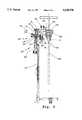
- FIG. 1is isometric drawing showing a tibial resection guide alignment apparatus embodying the principles of the invention.
- FIG. 2is a partial longitudinal section view taken along line 2--2 in FIG. 1.
- FIG. 3is a view in section taken along line 3--3 through the varus/valgus adjustment mechanism.
- FIG. 4is a partial longitudinal section view of the guide block mount with the depth stylus in position for providing a depth indication.
- FIG. 5is a partial longitudinal section view similar to FIG. 4 but showing the slope stylus in position for providing a visual indication of the guide slope.
- FIGS. 1 and 2show the tibial resection guide alignment apparatus 10 including a base member 12 having a base opening 14 extending along its length along a depth adjustment axis D.
- a carriage member 16is slideably received over the base member 12.
- the apparatus 10also includes a guide block mount 20 pivotally connected to the carriage 16 so as to pivot about a slope adjustment axis S extending perpendicular to the depth adjustment axis D.
- the base member 12also has associated with it depth adjustment means 22 for positioning the carriage along the depth adjustment axis D, and slope adjustment means 24 for positioning the guide block mount about the slope adjustment axis S.
- resection guide connecting means 26 associated with the guide block mount 20allows a resection guide 28 (shown in phantom) to be connected to the guide block mount for alignment.
- the slope adjustment means 24includes the nut 18 received in the base opening 14 and a slope adjustment member 30 threaded through the carriage member 16 and the nut, and terminating in a pivot connection 32 to the guide block mount 20.
- the threaded slope adjustment member 30may be threaded in and out through the carriage member 16 and nut 18 to force the guide block mount 20 to pivot about the slope adjustment axis S and provide fine posterior/anterior slope adjustment for the resection guide 28 connected to the guide block mount 20.
- the depth adjustment means 22includes slots 40 extending along a portion of the base member 12 through which the threaded slope adjustment member 30 passes, and a threaded depth adjustment member 42.
- the depth adjustment member 42is threaded through the base opening 14 and rotateably connected at one end to the nut 18.
- the depth adjustment member 42threads in and out through the base member 12 to provide fine depth adjustment by forcing the nut 18 through the base member opening 14 and along with the nut, the carriage member 16, threaded slope adjustment member 30, and the guide block mount 20.
- the resection guide connecting means 26includes a connecting member 44 extending through an opening through the guide block mount 20 and terminating in a threaded end section 48.
- the threaded end section 48is adapted to cooperate with a female threaded opening on the resection guide 28.
- the resection guide 28is connected to the guide block mount 20 in this form of the invention by aligning the resection guide on the bottom surface of the guide block mount and turning the threaded connecting member 44 to start the threaded end 48 into the female threaded opening on the resection guide 28 and draw the resection guide tightly against the bottom surface of the guide block mount 20.
- the resection guide connecting means 26preferably includes an alignment feature 50 formed on the bottom surface of the guide block mount 20. The alignment feature 50 registers with openings formed on the top of the resection guide 28 to allow the resection guide to be connected in only one position on the guide block mount 20 and ensure that the resection guide 28 is properly connected.
- a connecting arm member 60is connected to a top end of the base member 12.
- the connecting arm 60extends in the direction in which the guide block mount 20 is separated from the base member 12 and includes an end section 62 which is adapted to extend over the top of a surgically exposed proximal end of a tibia when the base member is properly connected to the tibia in an operating position.
- a slot in the connecting arm 60accepts the threaded connecting member 44 with a knurled end 45 of the threaded connecting member extending conveniently above the connecting arm.
- two or more engagement or spike members 64extend downwardly from the end section 62 of the connecting arm 60 in position to be driven into the top of the proximal end of the tibia with the base member in the operating position extending downwardly along the anterior side of the tibia.
- the connecting arm 60includes an opening 66 extending through the arm end section 62 for receiving an intramedullary mounting rod 68 (shown in phantom).
- the apparatus 10also includes an extension member 70 connected to the base member 12 and extending downwardly from the base member in a plane defined substantially by the depth adjustment axis D and the connecting arm 60.
- the extramedullary mounting arrangementalso includes an extramedullary mounting member 72 that may be removably connected to extension member 70 and locked in place with a suitable locking mechanism 74.
- the locking mechanismallows the overall length of the extramedullary mounting structure to be adjusted to the length of the tibia.
- a bottom assembly 76extends at substantially a fight angle to the axis of the extramedullary mounting member 72 and includes a cradle assembly 78 for securing around the patient's ankle or lower leg.
- the bottom assembly 76may also include a receptacle 80 extending in the opposite direction from the ankle cradle assembly 78 for receiving an alignment rod (not shown) which a physician may use in aligning the device 10 on a patient's tibia.
- the preferred extramedullary mounting arrangementalso includes varus/valgus adjusting means 84 associated with the bottom assembly 76 and the extramedullary mounting member 72.
- the varus/valgus adjusting mechanism 84comprises a threaded adjustment member 86 connected to knurled knobs 88, and a slide device 90 that is threaded over the threaded adjustment member and is connected to the ankle cradle assembly 78. Turning the threaded adjustment member 86 using the knurled knobs 88 causes the threaded slide device 90 to move laterally along the threaded adjustment member 88 therefore moving the ankle cradle assembly laterally as well.
- the apparatuspreferably includes a combination depth stylus and slope stylus 100 that may be connected to the resection guide 28 through a stylus connecting member 102.
- the stylus connecting member 102preferably includes an end section 104 adapted to extend into an opening through the resection guide 28.
- the preferred combined depth stylus and slope stylus 100includes an elongated center section 106 having a slot 108 through which the device may be connected to the top of the stylus connecting member 102.
- the top of the stylus connecting member 102includes a reduced diameter section 110 that may extend through the slot 108 with a cap member 112 threaded over the reduced diameter section 110 to fix the combined stylus 100 in the desired position.
- the stylusincludes a depth stylus section 114.
- the depth stylus section 114has an end 116 that terminates in a depth plane extending parallel to the plane G of the resection guide 28 guide surface when the guide is properly connected on the guide block mount 20.
- the depth plane Xis also separated from the plane G of the resection guide a distance equal to an implant thickness.
- the opposite end of the unitary stylus 100includes a slope stylus section 118 terminating with an elongated slope member 120 that lies in the plane X defined by the guide surface of the resection guide 28 properly received on the guide block mount 20.
- the resection guide 28is connected in position on the guide block mount 20 using the connecting member 44.
- the apparatus 10is positioned with the end 62 of the connecting arm 60 extending over the surgically exposed proximal end of the patient's tibia T (FIGS. 4 and 5) and with the base member 12 extending downwardly on the anterior side of the tibia.
- the connecting arm end section 62is driven downwardly driving the spikes 64 into the proximal end of the tibia.
- the intramedullary rod 68is inserted through opening 66 or the extramedullary mounting member 72 is attached over the rod 70 extending from the base member 12.
- Either mounting methodstabilizes the base member 12 in front of the tibia T where the fine posterior/anterior slope adjustment and depth adjustment can be made to properly align the resection guide 28.
- the stylus 100is rotated to position the elongated slope stylus member 120 over, or adjacent to, the tibial plateau and the threaded depth adjustment member 42 is rotated to position the slope stylus member 120 just above the tibia as shown in FIG. 5.
- the slope adjustment member 30may be threaded in or out to provide fine slope adjustment until the slope of the elongated slope stylus member 120 matches the slope of the natural tibial plateau. Once the slope is matched, the stylus 100 is rotated again to position the depth stylus section over the proximal end of the tibia as shown in FIG. 4.
- the threaded depth adjustment member 42can then be turned to move the resection guide 28 and guide block mount 20 downwardly parallel to the depth adjustment axis D until the depth stylus end 116 contacts the proximal end of the tibia T. Both the slope and depth of the resection guide 28 is now set and the resection guide may be temporarily fixed by suitable means to the anterior side of the tibial plateau prior to releasing the guide 28 from the guide block 20 and removing the alignment apparatus 10.
- the apparatus 10also provides a fine varus/valgus angle adjustment through the adjustment mechanism 84 associated with the bottom assembly 76 and the bottom of the extramedullary mounting member 72.
- the adjustment mechanism 84associated with the bottom assembly 76 and the bottom of the extramedullary mounting member 72.
- the lateral/medial or varus/valgus angle of the attached resection guide 28may be adjusted.
- a rod(not shown) may be inserted in the receptacle 80 for providing an alignment reference for the varus/valgus adjustment.
- the resection guide 28may be secured to the guide block mount 20 by any arrangement that allows the guide 28 to be released readily for removing the apparatus 10.
- the extramedullary mounting arrangementmay include any suitable bottom assembly for providing the desired extramedullary connection.
- the slope stylus and depth stylusmay be separate devices rather than the unitary device shown in the figures. The slope stylus and depth stylus may, in any event, be mounted on the resection guide directly or on the guide block mount.
Landscapes
- Health & Medical Sciences (AREA)
- Life Sciences & Earth Sciences (AREA)
- Surgery (AREA)
- Dentistry (AREA)
- Biomedical Technology (AREA)
- Oral & Maxillofacial Surgery (AREA)
- Nuclear Medicine, Radiotherapy & Molecular Imaging (AREA)
- Physical Education & Sports Medicine (AREA)
- Orthopedic Medicine & Surgery (AREA)
- Engineering & Computer Science (AREA)
- Transplantation (AREA)
- Heart & Thoracic Surgery (AREA)
- Medical Informatics (AREA)
- Molecular Biology (AREA)
- Animal Behavior & Ethology (AREA)
- General Health & Medical Sciences (AREA)
- Public Health (AREA)
- Veterinary Medicine (AREA)
- Surgical Instruments (AREA)
Abstract
Description
Claims (13)
Priority Applications (1)
| Application Number | Priority Date | Filing Date | Title |
|---|---|---|---|
| US08/496,980US5628750A (en) | 1995-06-30 | 1995-06-30 | Tibial resection guide alignment apparatus and method |
Applications Claiming Priority (1)
| Application Number | Priority Date | Filing Date | Title |
|---|---|---|---|
| US08/496,980US5628750A (en) | 1995-06-30 | 1995-06-30 | Tibial resection guide alignment apparatus and method |
Publications (1)
| Publication Number | Publication Date |
|---|---|
| US5628750Atrue US5628750A (en) | 1997-05-13 |
Family
ID=23974973
Family Applications (1)
| Application Number | Title | Priority Date | Filing Date |
|---|---|---|---|
| US08/496,980Expired - LifetimeUS5628750A (en) | 1995-06-30 | 1995-06-30 | Tibial resection guide alignment apparatus and method |
Country Status (1)
| Country | Link |
|---|---|
| US (1) | US5628750A (en) |
Cited By (75)
| Publication number | Priority date | Publication date | Assignee | Title |
|---|---|---|---|---|
| US5916219A (en)* | 1997-02-10 | 1999-06-29 | Matsuno; Shigeo | Tibial plateau resection guide |
| US6090114A (en)* | 1997-02-10 | 2000-07-18 | Stryker Howmedica Osteonics Corp. | Tibial plateau resection guide |
| US6193724B1 (en)* | 1998-11-25 | 2001-02-27 | Kwan-Ho Chan | Apparatus and method for determining the relative position of bones during surgery |
| US6221035B1 (en) | 1998-11-16 | 2001-04-24 | Richard J. Kana | Automatic ankle clamp |
| US6267762B1 (en)* | 1999-04-01 | 2001-07-31 | Aesculap | Device for the positioning of a proximal extremity of a tibia against a cutting guide including an adjusting handle |
| KR100407894B1 (en)* | 2001-09-07 | 2003-12-01 | 한국과학기술원 | A Gauge Device For Surgical Replacing Operation Of A Coxa |
| US20040015173A1 (en)* | 2002-01-25 | 2004-01-22 | Irving John F. | Extramedullary fluoroscopic alignment guide |
| US6702824B2 (en) | 1999-09-10 | 2004-03-09 | Depuy Orthopaedics, Inc. | Prosthesis positioning apparatus |
| GB2398011A (en)* | 2003-02-04 | 2004-08-11 | Robert Michael Wozencroft | Alignment device for use in orthapaedic surgery |
| US20040172044A1 (en)* | 2002-12-20 | 2004-09-02 | Grimm James E. | Surgical instrument and method of positioning same |
| US20040249387A1 (en)* | 2003-04-25 | 2004-12-09 | Francisco Faoro | Apparatus for the preparation of a femoral condyle |
| US20050021044A1 (en)* | 2003-06-09 | 2005-01-27 | Vitruvian Orthopaedics, Llc | Surgical orientation device and method |
| US20050059980A1 (en)* | 2003-09-15 | 2005-03-17 | Centerpulse Orthopedics Ltd. | Adjustment apparatus |
| US20050070910A1 (en)* | 2001-08-10 | 2005-03-31 | Greg Keene | Tibial resection guide |
| US20050143746A1 (en)* | 2003-12-26 | 2005-06-30 | Steffensmeier Scott J. | Adjustable resection guide |
| US20050182415A1 (en)* | 2003-12-26 | 2005-08-18 | Zimmer Technology, Inc. | Adjustable resection guide |
| US20050209605A1 (en)* | 2002-12-20 | 2005-09-22 | Grimm James E | Navigated orthopaedic guide and method |
| EP1598021A1 (en)* | 2004-05-17 | 2005-11-23 | Centerpulse Orthopedics Ltd. | Device for positioning of guide block for tibial resection |
| US20060004373A1 (en)* | 2004-06-30 | 2006-01-05 | Ondrla Jeffrey M | Adjustable humeral cutting guide |
| US20060122618A1 (en)* | 2004-03-08 | 2006-06-08 | Zimmer Technology, Inc. | Navigated cut guide locator |
| US20060149276A1 (en)* | 2002-12-20 | 2006-07-06 | Grimm James E | Surgical instrument and positioning method |
| US20060155293A1 (en)* | 2005-01-07 | 2006-07-13 | Zimmer Technology | External rotation cut guide |
| US20060184173A1 (en)* | 2005-02-17 | 2006-08-17 | Howmedica Osteonics Corp. | Locking intramedullary jig |
| US20060200159A1 (en)* | 2005-02-18 | 2006-09-07 | Howmedica Osteonics Corp. | Pin extraction assembly |
| US20060200158A1 (en)* | 2005-01-29 | 2006-09-07 | Farling Toby N | Apparatuses and methods for arthroplastic surgery |
| US20060247647A1 (en)* | 2002-11-27 | 2006-11-02 | Zimmer Technology, Inc. | Method and apparatus for achieving correct limb alignment in unicondylar knee arthroplasty |
| US20070149977A1 (en)* | 2005-11-28 | 2007-06-28 | Zimmer Technology, Inc. | Surgical component positioner |
| US20070173854A1 (en)* | 2006-01-23 | 2007-07-26 | Berger Richard A | Bone resection apparatus and method for knee surgery |
| US20070173850A1 (en)* | 2006-01-10 | 2007-07-26 | Zimmer Technology, Inc. | Bone resection guide and method |
| US20070186738A1 (en)* | 2006-01-31 | 2007-08-16 | Zimmer Technology, Inc. | Tibial cut guide assembly having rotatable cut guide body |
| US20080177261A1 (en)* | 2007-01-13 | 2008-07-24 | Mcminn Derek James Wallace | Instrumentation for knee surgery |
| US20080228189A1 (en)* | 2007-03-13 | 2008-09-18 | Biomet Manufacturing Corp | Distal femoral cutting guide |
| US20080275566A1 (en)* | 2007-05-04 | 2008-11-06 | Lewis Randall J | Femoral hip stem explant system |
| WO2009037470A1 (en)* | 2007-09-21 | 2009-03-26 | Depuy International Ltd | Surgical instrument attachment |
| US7520880B2 (en) | 2006-01-09 | 2009-04-21 | Zimmer Technology, Inc. | Adjustable surgical support base with integral hinge |
| US7559931B2 (en) | 2003-06-09 | 2009-07-14 | OrthAlign, Inc. | Surgical orientation system and method |
| US20090234360A1 (en)* | 2006-12-12 | 2009-09-17 | Vladimir Alexander | Laser assisted total joint arthroplasty |
| US20100063508A1 (en)* | 2008-07-24 | 2010-03-11 | OrthAlign, Inc. | Systems and methods for joint replacement |
| US20100094300A1 (en)* | 2003-02-03 | 2010-04-15 | Zimmer, Inc. | Apparatus for knee surgery and method of use |
| WO2011072249A1 (en)* | 2009-12-11 | 2011-06-16 | Small Bone Innovations, Inc. | Ankle fusion device, instrumentation and methods |
| US7993341B2 (en) | 2004-03-08 | 2011-08-09 | Zimmer Technology, Inc. | Navigated orthopaedic guide and method |
| US20110208093A1 (en)* | 2010-01-21 | 2011-08-25 | OrthAlign, Inc. | Systems and methods for joint replacement |
| US20110218543A1 (en)* | 2009-07-24 | 2011-09-08 | OrthAlign, Inc. | Systems and methods for joint replacement |
| USD649638S1 (en)* | 2010-05-28 | 2011-11-29 | Zimmer, Inc. | Tibial depth resection stylus |
| USD651313S1 (en)* | 2010-05-28 | 2011-12-27 | Zimmer, Inc. | Extramedullary telescoping tube |
| US20120101504A1 (en)* | 2010-10-22 | 2012-04-26 | Zimmer, Inc. | Flexible attachment for an extramedullary surgical instrument |
| US8167888B2 (en) | 2004-08-06 | 2012-05-01 | Zimmer Technology, Inc. | Tibial spacer blocks and femoral cutting guide |
| US8425522B2 (en) | 2000-01-14 | 2013-04-23 | Bonutti Skeletal Innovations Llc | Joint replacement method |
| US20130204260A1 (en)* | 2012-02-06 | 2013-08-08 | Zimmer, Inc. | Cone lock quick connect mechanism |
| US8623030B2 (en) | 2001-08-28 | 2014-01-07 | Bonutti Skeletal Innovations Llc | Robotic arthroplasty system including navigation |
| US8974468B2 (en) | 2008-09-10 | 2015-03-10 | OrthAlign, Inc. | Hip surgery systems and methods |
| US8986315B2 (en) | 2011-05-25 | 2015-03-24 | DePuy Synthes Products, LLC | Aiming device having radio-opaque markers |
| US9078674B2 (en)* | 2007-09-21 | 2015-07-14 | Depuy (Ireland) | Adjustable surgical instrument |
| US9549742B2 (en) | 2012-05-18 | 2017-01-24 | OrthAlign, Inc. | Devices and methods for knee arthroplasty |
| US9649160B2 (en) | 2012-08-14 | 2017-05-16 | OrthAlign, Inc. | Hip replacement navigation system and method |
| US20170135708A1 (en)* | 2015-11-12 | 2017-05-18 | Zimmer, Inc. | Assembly for a tibial cut guide |
| CN107233121A (en)* | 2017-07-15 | 2017-10-10 | 常州奥斯迈医疗器械有限公司 | Shin bone adjusts seat |
| US10285714B2 (en) | 2016-09-15 | 2019-05-14 | Biomet Manufacturing, Llc | Assembly and system including a tibial cut guide |
| US10357256B2 (en) | 2016-09-15 | 2019-07-23 | Biomet Manufacturing, Llc | Assembly and system including a tibial cut guide |
| US10363149B2 (en) | 2015-02-20 | 2019-07-30 | OrthAlign, Inc. | Hip replacement navigation system and method |
| US10517614B2 (en) | 2015-06-19 | 2019-12-31 | Zimmer, Inc. | Tibial cut guide |
| WO2020109499A1 (en)* | 2018-11-28 | 2020-06-04 | Aesculap Ag | Fixing clamp and aligning device |
| WO2020124044A1 (en)* | 2018-12-13 | 2020-06-18 | Paragon 28, Inc. | Joint replacement alignment guides, systems and methods of use and assembly |
| CN111870310A (en)* | 2020-08-04 | 2020-11-03 | 北京力达康科技有限公司 | An extramedullary and intramedullary multifunctional positioning system for tibial osteotomy |
| US10835262B2 (en) | 2017-12-06 | 2020-11-17 | Howmedica Osteonics Corp. | Tibial posterior slope alignment guide |
| US10863995B2 (en) | 2017-03-14 | 2020-12-15 | OrthAlign, Inc. | Soft tissue measurement and balancing systems and methods |
| US10869771B2 (en) | 2009-07-24 | 2020-12-22 | OrthAlign, Inc. | Systems and methods for joint replacement |
| US10918499B2 (en) | 2017-03-14 | 2021-02-16 | OrthAlign, Inc. | Hip replacement navigation systems and methods |
| US11272942B2 (en) | 2016-09-15 | 2022-03-15 | Biomet Manufacturing, Llc | Assembly and system including a tibial cut guide |
| US20220167999A1 (en) | 2018-12-13 | 2022-06-02 | Paragon 28, Inc. | Alignment instruments and methods for use in total ankle replacement |
| US11666346B2 (en) | 2007-03-23 | 2023-06-06 | Xiros Limited | Surgical templates |
| US11751883B2 (en) | 2018-11-28 | 2023-09-12 | Aesculap Ag | Fixing system and aligning device |
| US12042157B2 (en) | 2019-02-15 | 2024-07-23 | Aesculap Ag | Fixing clamp and aligning device |
| US12133804B2 (en) | 2018-12-13 | 2024-11-05 | Paragon 28, Inc. | Total ankle replacement surgical method |
| US12156664B2 (en) | 2018-12-13 | 2024-12-03 | Paragon 28, Inc. | Resection guides, sweeping reamers, and methods for use in total ankle replacement |
Citations (4)
| Publication number | Priority date | Publication date | Assignee | Title |
|---|---|---|---|---|
| US4841975A (en)* | 1987-04-15 | 1989-06-27 | Cemax, Inc. | Preoperative planning of bone cuts and joint replacement using radiant energy scan imaging |
| US4952213A (en)* | 1989-02-03 | 1990-08-28 | Boehringer Mannheim Corporation | Tibial cutting guide |
| US5342368A (en)* | 1992-07-08 | 1994-08-30 | Petersen Thomas D | Intramedullary universal proximal tibial resector guide |
| US5395377A (en)* | 1993-09-21 | 1995-03-07 | Petersen; Thomas D. | Extramedullary proximal tibial guide |
- 1995
- 1995-06-30USUS08/496,980patent/US5628750A/ennot_activeExpired - Lifetime
Patent Citations (4)
| Publication number | Priority date | Publication date | Assignee | Title |
|---|---|---|---|---|
| US4841975A (en)* | 1987-04-15 | 1989-06-27 | Cemax, Inc. | Preoperative planning of bone cuts and joint replacement using radiant energy scan imaging |
| US4952213A (en)* | 1989-02-03 | 1990-08-28 | Boehringer Mannheim Corporation | Tibial cutting guide |
| US5342368A (en)* | 1992-07-08 | 1994-08-30 | Petersen Thomas D | Intramedullary universal proximal tibial resector guide |
| US5395377A (en)* | 1993-09-21 | 1995-03-07 | Petersen; Thomas D. | Extramedullary proximal tibial guide |
Non-Patent Citations (9)
| Title |
|---|
| PFC Modular Total Knee System, 1990, pp. 18 27.* |
| PFC Modular Total Knee System, 1990, pp. 18-27. |
| Surgical Technique with the Howmedia Universal Knee Instruments, pp. 15 21.* |
| Surgical Technique with the Howmedia Universal Knee Instruments, pp. 15-21. |
| The Continuum Knee System Surgical Technique, pp. 9 10.* |
| The Continuum Knee System Surgical Technique, pp. 9-10. |
| The Intermedics Natural Knee System, 1992, pp. 14 19.* |
| The Intermedics Natural-Knee System, 1992, pp. 14-19. |
| Zimmer Adjustable Tibial Resector, 1992.* |
Cited By (179)
| Publication number | Priority date | Publication date | Assignee | Title |
|---|---|---|---|---|
| US6090114A (en)* | 1997-02-10 | 2000-07-18 | Stryker Howmedica Osteonics Corp. | Tibial plateau resection guide |
| US5916219A (en)* | 1997-02-10 | 1999-06-29 | Matsuno; Shigeo | Tibial plateau resection guide |
| US6221035B1 (en) | 1998-11-16 | 2001-04-24 | Richard J. Kana | Automatic ankle clamp |
| US6193724B1 (en)* | 1998-11-25 | 2001-02-27 | Kwan-Ho Chan | Apparatus and method for determining the relative position of bones during surgery |
| US6632226B2 (en)* | 1998-11-25 | 2003-10-14 | Kwan-Ho Chan | Apparatus and method for determining the relative position of bones during surgery |
| US6267762B1 (en)* | 1999-04-01 | 2001-07-31 | Aesculap | Device for the positioning of a proximal extremity of a tibia against a cutting guide including an adjusting handle |
| WO2001000096A1 (en)* | 1999-06-29 | 2001-01-04 | Howmedica Osteonics Corp. | Tibial plateau resection guide |
| AU762838B2 (en)* | 1999-06-29 | 2003-07-03 | Howmedica Osteonics Corp. | Tibial plateau resection guide |
| EP1194075A4 (en)* | 1999-06-29 | 2006-01-04 | Howmedica Osteonics Corp | Tibial plateau resection guide |
| US6702824B2 (en) | 1999-09-10 | 2004-03-09 | Depuy Orthopaedics, Inc. | Prosthesis positioning apparatus |
| US9795394B2 (en) | 2000-01-14 | 2017-10-24 | Bonutti Skeletal Innovations Llc | Method for placing implant using robotic system |
| US8425522B2 (en) | 2000-01-14 | 2013-04-23 | Bonutti Skeletal Innovations Llc | Joint replacement method |
| US9192459B2 (en) | 2000-01-14 | 2015-11-24 | Bonutti Skeletal Innovations Llc | Method of performing total knee arthroplasty |
| US9101443B2 (en) | 2000-01-14 | 2015-08-11 | Bonutti Skeletal Innovations Llc | Methods for robotic arthroplasty |
| US8784495B2 (en) | 2000-01-14 | 2014-07-22 | Bonutti Skeletal Innovations Llc | Segmental knee arthroplasty |
| US8632552B2 (en) | 2000-01-14 | 2014-01-21 | Bonutti Skeletal Innovations Llc | Method of preparing a femur and tibia in knee arthroplasty |
| US20050070910A1 (en)* | 2001-08-10 | 2005-03-31 | Greg Keene | Tibial resection guide |
| US9763683B2 (en) | 2001-08-28 | 2017-09-19 | Bonutti Skeletal Innovations Llc | Method for performing surgical procedures using optical cutting guides |
| US10231739B1 (en) | 2001-08-28 | 2019-03-19 | Bonutti Skeletal Innovations Llc | System and method for robotic surgery |
| US10470780B2 (en) | 2001-08-28 | 2019-11-12 | Bonutti Skeletal Innovations Llc | Systems and methods for ligament balancing in robotic surgery |
| US8641726B2 (en) | 2001-08-28 | 2014-02-04 | Bonutti Skeletal Innovations Llc | Method for robotic arthroplasty using navigation |
| US8840629B2 (en) | 2001-08-28 | 2014-09-23 | Bonutti Skeletal Innovations Llc | Robotic arthroplasty system including navigation |
| US8858557B2 (en) | 2001-08-28 | 2014-10-14 | Bonutti Skeletal Innovations Llc | Method of preparing a femur and tibia in knee arthroplasty |
| US8623030B2 (en) | 2001-08-28 | 2014-01-07 | Bonutti Skeletal Innovations Llc | Robotic arthroplasty system including navigation |
| US9060797B2 (en) | 2001-08-28 | 2015-06-23 | Bonutti Skeletal Innovations Llc | Method of preparing a femur and tibia in knee arthroplasty |
| US10321918B2 (en) | 2001-08-28 | 2019-06-18 | Bonutti Skeletal Innovations Llc | Methods for robotic surgery using a cannula |
| US8834490B2 (en) | 2001-08-28 | 2014-09-16 | Bonutti Skeletal Innovations Llc | Method for robotic arthroplasty using navigation |
| KR100407894B1 (en)* | 2001-09-07 | 2003-12-01 | 한국과학기술원 | A Gauge Device For Surgical Replacing Operation Of A Coxa |
| US7083624B2 (en)* | 2002-01-25 | 2006-08-01 | Depuy Products, Inc. | Extramedullary fluoroscopic alignment guide |
| US7763027B2 (en) | 2002-01-25 | 2010-07-27 | Depuy Products, Inc. | Extramedullary fluoroscopic alignment guide |
| US20060235420A1 (en)* | 2002-01-25 | 2006-10-19 | Depuy Products, Inc. | Extramedullary fluoroscopic alignment guide |
| US20040015173A1 (en)* | 2002-01-25 | 2004-01-22 | Irving John F. | Extramedullary fluoroscopic alignment guide |
| US8454616B2 (en) | 2002-11-27 | 2013-06-04 | Zimmer, Inc. | Method and apparatus for achieving correct limb alignment in unicondylar knee arthroplasty |
| US7842039B2 (en) | 2002-11-27 | 2010-11-30 | Zimmer Technology, Inc. | Method and apparatus for achieving correct limb alignment in unicondylar knee arthroplasty |
| US20060247647A1 (en)* | 2002-11-27 | 2006-11-02 | Zimmer Technology, Inc. | Method and apparatus for achieving correct limb alignment in unicondylar knee arthroplasty |
| US20050209605A1 (en)* | 2002-12-20 | 2005-09-22 | Grimm James E | Navigated orthopaedic guide and method |
| US20060149276A1 (en)* | 2002-12-20 | 2006-07-06 | Grimm James E | Surgical instrument and positioning method |
| US20070282347A9 (en)* | 2002-12-20 | 2007-12-06 | Grimm James E | Navigated orthopaedic guide and method |
| US20040172044A1 (en)* | 2002-12-20 | 2004-09-02 | Grimm James E. | Surgical instrument and method of positioning same |
| US8118811B2 (en)* | 2003-02-03 | 2012-02-21 | Zimmer, Inc. | Apparatus for knee surgery and method of use |
| US20100094300A1 (en)* | 2003-02-03 | 2010-04-15 | Zimmer, Inc. | Apparatus for knee surgery and method of use |
| GB2398011A (en)* | 2003-02-04 | 2004-08-11 | Robert Michael Wozencroft | Alignment device for use in orthapaedic surgery |
| US20040249387A1 (en)* | 2003-04-25 | 2004-12-09 | Francisco Faoro | Apparatus for the preparation of a femoral condyle |
| US7527630B2 (en) | 2003-04-25 | 2009-05-05 | Zimmer, Gmbh | Apparatus for the preparation of a femoral condyle |
| US8057479B2 (en) | 2003-06-09 | 2011-11-15 | OrthAlign, Inc. | Surgical orientation system and method |
| US11179167B2 (en) | 2003-06-09 | 2021-11-23 | OrthAlign, Inc. | Surgical orientation system and method |
| US20050021044A1 (en)* | 2003-06-09 | 2005-01-27 | Vitruvian Orthopaedics, Llc | Surgical orientation device and method |
| US8057482B2 (en) | 2003-06-09 | 2011-11-15 | OrthAlign, Inc. | Surgical orientation device and method |
| US7559931B2 (en) | 2003-06-09 | 2009-07-14 | OrthAlign, Inc. | Surgical orientation system and method |
| US8888786B2 (en) | 2003-06-09 | 2014-11-18 | OrthAlign, Inc. | Surgical orientation device and method |
| US11903597B2 (en) | 2003-06-09 | 2024-02-20 | OrthAlign, Inc. | Surgical orientation system and method |
| US20090318931A1 (en)* | 2003-06-09 | 2009-12-24 | OrthAlign, Inc. | Surgical orientation device and method |
| US8974467B2 (en) | 2003-06-09 | 2015-03-10 | OrthAlign, Inc. | Surgical orientation system and method |
| US20100016705A1 (en)* | 2003-06-09 | 2010-01-21 | Orthalign, Inc | Surgical orientation system and method |
| US7648510B2 (en) | 2003-09-15 | 2010-01-19 | Zimmer, Gmbh | Adjustment apparatus |
| US20050059980A1 (en)* | 2003-09-15 | 2005-03-17 | Centerpulse Orthopedics Ltd. | Adjustment apparatus |
| US7335206B2 (en) | 2003-12-26 | 2008-02-26 | Zimmer Technology, Inc. | Adjustable resection guide |
| US7641661B2 (en) | 2003-12-26 | 2010-01-05 | Zimmer Technology, Inc. | Adjustable resection guide |
| US20050182415A1 (en)* | 2003-12-26 | 2005-08-18 | Zimmer Technology, Inc. | Adjustable resection guide |
| US20050143746A1 (en)* | 2003-12-26 | 2005-06-30 | Steffensmeier Scott J. | Adjustable resection guide |
| US20060122618A1 (en)* | 2004-03-08 | 2006-06-08 | Zimmer Technology, Inc. | Navigated cut guide locator |
| US8114086B2 (en) | 2004-03-08 | 2012-02-14 | Zimmer Technology, Inc. | Navigated cut guide locator |
| US7993341B2 (en) | 2004-03-08 | 2011-08-09 | Zimmer Technology, Inc. | Navigated orthopaedic guide and method |
| EP1598021A1 (en)* | 2004-05-17 | 2005-11-23 | Centerpulse Orthopedics Ltd. | Device for positioning of guide block for tibial resection |
| US20050261696A1 (en)* | 2004-05-17 | 2005-11-24 | Zimmer Gmbh | Apparatus for setting a cutting block for a resection of the tibia |
| US20060004373A1 (en)* | 2004-06-30 | 2006-01-05 | Ondrla Jeffrey M | Adjustable humeral cutting guide |
| US7198628B2 (en)* | 2004-06-30 | 2007-04-03 | Depuy Products, Inc. | Adjustable humeral cutting guide |
| US8167888B2 (en) | 2004-08-06 | 2012-05-01 | Zimmer Technology, Inc. | Tibial spacer blocks and femoral cutting guide |
| US20060155293A1 (en)* | 2005-01-07 | 2006-07-13 | Zimmer Technology | External rotation cut guide |
| US20060200158A1 (en)* | 2005-01-29 | 2006-09-07 | Farling Toby N | Apparatuses and methods for arthroplastic surgery |
| US20060184173A1 (en)* | 2005-02-17 | 2006-08-17 | Howmedica Osteonics Corp. | Locking intramedullary jig |
| US7618420B2 (en)* | 2005-02-17 | 2009-11-17 | Howmedica Osteonics Corp. | Locking intramedullary jig |
| US20080183178A1 (en)* | 2005-02-17 | 2008-07-31 | Howmedica Osteonics Corp. | Locking intramedullary jig |
| US7344542B2 (en)* | 2005-02-18 | 2008-03-18 | Howmedica Osteonics Corp. | Pin extraction assembly |
| US20060200159A1 (en)* | 2005-02-18 | 2006-09-07 | Howmedica Osteonics Corp. | Pin extraction assembly |
| US20070149977A1 (en)* | 2005-11-28 | 2007-06-28 | Zimmer Technology, Inc. | Surgical component positioner |
| US7520880B2 (en) | 2006-01-09 | 2009-04-21 | Zimmer Technology, Inc. | Adjustable surgical support base with integral hinge |
| US20070173850A1 (en)* | 2006-01-10 | 2007-07-26 | Zimmer Technology, Inc. | Bone resection guide and method |
| US7744600B2 (en) | 2006-01-10 | 2010-06-29 | Zimmer Technology, Inc. | Bone resection guide and method |
| US7780671B2 (en) | 2006-01-23 | 2010-08-24 | Zimmer Technology, Inc. | Bone resection apparatus and method for knee surgery |
| US20070173854A1 (en)* | 2006-01-23 | 2007-07-26 | Berger Richard A | Bone resection apparatus and method for knee surgery |
| US20100286699A1 (en)* | 2006-01-23 | 2010-11-11 | Zimmer Technology, Inc. | Bone resection apparatus and method for knee surgery |
| US20070186738A1 (en)* | 2006-01-31 | 2007-08-16 | Zimmer Technology, Inc. | Tibial cut guide assembly having rotatable cut guide body |
| US20090234360A1 (en)* | 2006-12-12 | 2009-09-17 | Vladimir Alexander | Laser assisted total joint arthroplasty |
| US20080177261A1 (en)* | 2007-01-13 | 2008-07-24 | Mcminn Derek James Wallace | Instrumentation for knee surgery |
| US9113923B2 (en) | 2007-03-13 | 2015-08-25 | Biomet Manufacturing, Llc. | Distal femoral cutting guide |
| US8333772B2 (en) | 2007-03-13 | 2012-12-18 | Biomet Manufacturing Corp. | Distal femoral cutting guide |
| US7959637B2 (en)* | 2007-03-13 | 2011-06-14 | Biomet Manufacturing Corp. | Distal femoral cutting guide |
| US10238399B2 (en) | 2007-03-13 | 2019-03-26 | Biomet Manufacturing, Llc | Distal femoral cutting guide |
| US20080228189A1 (en)* | 2007-03-13 | 2008-09-18 | Biomet Manufacturing Corp | Distal femoral cutting guide |
| US9826982B2 (en) | 2007-03-13 | 2017-11-28 | Biomet Manufacturing, Llc | Distal femoral cutting guide |
| US11666346B2 (en) | 2007-03-23 | 2023-06-06 | Xiros Limited | Surgical templates |
| US11672548B2 (en) | 2007-03-23 | 2023-06-13 | Xiros Limited | Surgical templates |
| US20080275566A1 (en)* | 2007-05-04 | 2008-11-06 | Lewis Randall J | Femoral hip stem explant system |
| US9138242B2 (en)* | 2007-05-04 | 2015-09-22 | Randall J. Lewis | Femoral hip stem explant system |
| US9078674B2 (en)* | 2007-09-21 | 2015-07-14 | Depuy (Ireland) | Adjustable surgical instrument |
| US20100305488A1 (en)* | 2007-09-21 | 2010-12-02 | Depuy International Limited | Surgical instrument attachment |
| WO2009037470A1 (en)* | 2007-09-21 | 2009-03-26 | Depuy International Ltd | Surgical instrument attachment |
| US8496010B2 (en) | 2007-09-21 | 2013-07-30 | Depuy International Limited | Surgical instrument attachment |
| AU2008300429B2 (en)* | 2007-09-21 | 2013-11-07 | Depuy International Ltd | Surgical instrument attachment |
| US8911447B2 (en) | 2008-07-24 | 2014-12-16 | OrthAlign, Inc. | Systems and methods for joint replacement |
| US20100063508A1 (en)* | 2008-07-24 | 2010-03-11 | OrthAlign, Inc. | Systems and methods for joint replacement |
| US10206714B2 (en) | 2008-07-24 | 2019-02-19 | OrthAlign, Inc. | Systems and methods for joint replacement |
| US8998910B2 (en) | 2008-07-24 | 2015-04-07 | OrthAlign, Inc. | Systems and methods for joint replacement |
| US9192392B2 (en) | 2008-07-24 | 2015-11-24 | OrthAlign, Inc. | Systems and methods for joint replacement |
| US12239344B2 (en) | 2008-07-24 | 2025-03-04 | OrthAlign, Inc. | Systems and methods for joint replacement |
| US20100137869A1 (en)* | 2008-07-24 | 2010-06-03 | OrthAlign, Inc. | Systems and methods for joint replacement |
| US11547451B2 (en) | 2008-07-24 | 2023-01-10 | OrthAlign, Inc. | Systems and methods for joint replacement |
| US10864019B2 (en) | 2008-07-24 | 2020-12-15 | OrthAlign, Inc. | Systems and methods for joint replacement |
| US9855075B2 (en) | 2008-07-24 | 2018-01-02 | OrthAlign, Inc. | Systems and methods for joint replacement |
| US11871965B2 (en) | 2008-07-24 | 2024-01-16 | OrthAlign, Inc. | Systems and methods for joint replacement |
| US9572586B2 (en) | 2008-07-24 | 2017-02-21 | OrthAlign, Inc. | Systems and methods for joint replacement |
| US11684392B2 (en) | 2008-07-24 | 2023-06-27 | OrthAlign, Inc. | Systems and methods for joint replacement |
| US10321852B2 (en) | 2008-09-10 | 2019-06-18 | OrthAlign, Inc. | Hip surgery systems and methods |
| US11540746B2 (en) | 2008-09-10 | 2023-01-03 | OrthAlign, Inc. | Hip surgery systems and methods |
| US11179062B2 (en) | 2008-09-10 | 2021-11-23 | OrthAlign, Inc. | Hip surgery systems and methods |
| US8974468B2 (en) | 2008-09-10 | 2015-03-10 | OrthAlign, Inc. | Hip surgery systems and methods |
| US12232863B2 (en) | 2008-09-10 | 2025-02-25 | OrthAlign, Inc. | Hip surgery systems and methods |
| US9931059B2 (en) | 2008-09-10 | 2018-04-03 | OrthAlign, Inc. | Hip surgery systems and methods |
| US11633293B2 (en) | 2009-07-24 | 2023-04-25 | OrthAlign, Inc. | Systems and methods for joint replacement |
| US9775725B2 (en) | 2009-07-24 | 2017-10-03 | OrthAlign, Inc. | Systems and methods for joint replacement |
| US8118815B2 (en) | 2009-07-24 | 2012-02-21 | OrthAlign, Inc. | Systems and methods for joint replacement |
| US10869771B2 (en) | 2009-07-24 | 2020-12-22 | OrthAlign, Inc. | Systems and methods for joint replacement |
| US10238510B2 (en) | 2009-07-24 | 2019-03-26 | OrthAlign, Inc. | Systems and methods for joint replacement |
| US20110218543A1 (en)* | 2009-07-24 | 2011-09-08 | OrthAlign, Inc. | Systems and methods for joint replacement |
| US12318313B2 (en) | 2009-07-24 | 2025-06-03 | OrthAlign, Inc. | Systems and methods for joint replacement |
| US9271756B2 (en) | 2009-07-24 | 2016-03-01 | OrthAlign, Inc. | Systems and methods for joint replacement |
| US9308037B2 (en) | 2009-12-11 | 2016-04-12 | Stryker European Holdings I, Llc | Ankle fusion device, instrumentation and methods |
| WO2011072249A1 (en)* | 2009-12-11 | 2011-06-16 | Small Bone Innovations, Inc. | Ankle fusion device, instrumentation and methods |
| US8562606B2 (en) | 2009-12-11 | 2013-10-22 | Small Bone Innovations, Inc. | Ankle fusion device, instrumentation and methods |
| US20110208093A1 (en)* | 2010-01-21 | 2011-08-25 | OrthAlign, Inc. | Systems and methods for joint replacement |
| US9339226B2 (en) | 2010-01-21 | 2016-05-17 | OrthAlign, Inc. | Systems and methods for joint replacement |
| USD651313S1 (en)* | 2010-05-28 | 2011-12-27 | Zimmer, Inc. | Extramedullary telescoping tube |
| USD649638S1 (en)* | 2010-05-28 | 2011-11-29 | Zimmer, Inc. | Tibial depth resection stylus |
| US20120101504A1 (en)* | 2010-10-22 | 2012-04-26 | Zimmer, Inc. | Flexible attachment for an extramedullary surgical instrument |
| US8758354B2 (en)* | 2010-10-22 | 2014-06-24 | Zimmer, Inc. | Flexible attachment for an extramedullary surgical instrument |
| US8986315B2 (en) | 2011-05-25 | 2015-03-24 | DePuy Synthes Products, LLC | Aiming device having radio-opaque markers |
| US20130204260A1 (en)* | 2012-02-06 | 2013-08-08 | Zimmer, Inc. | Cone lock quick connect mechanism |
| US9265510B2 (en)* | 2012-02-06 | 2016-02-23 | Zimmer, Inc. | Cone lock quick connect mechanism |
| US10716580B2 (en) | 2012-05-18 | 2020-07-21 | OrthAlign, Inc. | Devices and methods for knee arthroplasty |
| US9549742B2 (en) | 2012-05-18 | 2017-01-24 | OrthAlign, Inc. | Devices and methods for knee arthroplasty |
| US11653981B2 (en) | 2012-08-14 | 2023-05-23 | OrthAlign, Inc. | Hip replacement navigation system and method |
| US12433694B2 (en) | 2012-08-14 | 2025-10-07 | OrthAlign, Inc. | Hip replacement navigation system and method |
| US10603115B2 (en) | 2012-08-14 | 2020-03-31 | OrthAlign, Inc. | Hip replacement navigation system and method |
| US12144567B2 (en) | 2012-08-14 | 2024-11-19 | OrthAlign, Inc. | Hip replacement navigation system and method |
| US11911119B2 (en) | 2012-08-14 | 2024-02-27 | OrthAlign, Inc. | Hip replacement navigation system and method |
| US9649160B2 (en) | 2012-08-14 | 2017-05-16 | OrthAlign, Inc. | Hip replacement navigation system and method |
| US10363149B2 (en) | 2015-02-20 | 2019-07-30 | OrthAlign, Inc. | Hip replacement navigation system and method |
| US12376972B2 (en) | 2015-02-20 | 2025-08-05 | OrthAlign, Inc. | Hip replacement navigation system and method |
| US11020245B2 (en) | 2015-02-20 | 2021-06-01 | OrthAlign, Inc. | Hip replacement navigation system and method |
| US12290272B2 (en) | 2015-06-19 | 2025-05-06 | Zimmer, Inc. | Tibial cut guide |
| US11406400B2 (en) | 2015-06-19 | 2022-08-09 | Zimmer, Inc. | Tibial cut guide |
| US10517614B2 (en) | 2015-06-19 | 2019-12-31 | Zimmer, Inc. | Tibial cut guide |
| US20170135708A1 (en)* | 2015-11-12 | 2017-05-18 | Zimmer, Inc. | Assembly for a tibial cut guide |
| US10245046B2 (en)* | 2015-11-12 | 2019-04-02 | Zimmer, Inc. | Assembly for a tibial cut guide |
| US10357256B2 (en) | 2016-09-15 | 2019-07-23 | Biomet Manufacturing, Llc | Assembly and system including a tibial cut guide |
| US10285714B2 (en) | 2016-09-15 | 2019-05-14 | Biomet Manufacturing, Llc | Assembly and system including a tibial cut guide |
| US11272942B2 (en) | 2016-09-15 | 2022-03-15 | Biomet Manufacturing, Llc | Assembly and system including a tibial cut guide |
| US11786261B2 (en) | 2017-03-14 | 2023-10-17 | OrthAlign, Inc. | Soft tissue measurement and balancing systems and methods |
| US10918499B2 (en) | 2017-03-14 | 2021-02-16 | OrthAlign, Inc. | Hip replacement navigation systems and methods |
| US11547580B2 (en) | 2017-03-14 | 2023-01-10 | OrthAlign, Inc. | Hip replacement navigation systems and methods |
| US10863995B2 (en) | 2017-03-14 | 2020-12-15 | OrthAlign, Inc. | Soft tissue measurement and balancing systems and methods |
| CN107233121A (en)* | 2017-07-15 | 2017-10-10 | 常州奥斯迈医疗器械有限公司 | Shin bone adjusts seat |
| US10835262B2 (en) | 2017-12-06 | 2020-11-17 | Howmedica Osteonics Corp. | Tibial posterior slope alignment guide |
| US11751883B2 (en) | 2018-11-28 | 2023-09-12 | Aesculap Ag | Fixing system and aligning device |
| JP2022509228A (en)* | 2018-11-28 | 2022-01-20 | エースクラップ アーゲー | Fixed clamp and alignment device |
| WO2020109499A1 (en)* | 2018-11-28 | 2020-06-04 | Aesculap Ag | Fixing clamp and aligning device |
| CN113164177A (en)* | 2018-11-28 | 2021-07-23 | 蛇牌股份公司 | Fixing clamp and orientation equipment |
| US11497509B2 (en)* | 2018-11-28 | 2022-11-15 | Aesculap Ag | Fixing clamp and aligning device |
| CN113164177B (en)* | 2018-11-28 | 2024-10-01 | 蛇牌股份公司 | Fixtures and Orientation Equipment |
| US12133804B2 (en) | 2018-12-13 | 2024-11-05 | Paragon 28, Inc. | Total ankle replacement surgical method |
| US12156664B2 (en) | 2018-12-13 | 2024-12-03 | Paragon 28, Inc. | Resection guides, sweeping reamers, and methods for use in total ankle replacement |
| US11871943B2 (en) | 2018-12-13 | 2024-01-16 | Paragon 28, Inc. | Alignment instruments and methods for use in total ankle replacement |
| US12239550B2 (en) | 2018-12-13 | 2025-03-04 | Paragon 28, Inc. | Joint replacement alignment guides, systems and methods of use and assembly |
| US11382765B2 (en) | 2018-12-13 | 2022-07-12 | Paragon 28, Inc. | Joint replacement alignment guides, systems and methods of use and assembly |
| WO2020124044A1 (en)* | 2018-12-13 | 2020-06-18 | Paragon 28, Inc. | Joint replacement alignment guides, systems and methods of use and assembly |
| US20220167999A1 (en) | 2018-12-13 | 2022-06-02 | Paragon 28, Inc. | Alignment instruments and methods for use in total ankle replacement |
| US12042157B2 (en) | 2019-02-15 | 2024-07-23 | Aesculap Ag | Fixing clamp and aligning device |
| CN111870310A (en)* | 2020-08-04 | 2020-11-03 | 北京力达康科技有限公司 | An extramedullary and intramedullary multifunctional positioning system for tibial osteotomy |
Similar Documents
| Publication | Publication Date | Title |
|---|---|---|
| US5628750A (en) | Tibial resection guide alignment apparatus and method | |
| US5601563A (en) | Orthopaedic milling template with attachable cutting guide | |
| US5860981A (en) | Guide for femoral milling instrumention for use in total knee arthroplasty | |
| US5681316A (en) | Tibial resection guide | |
| US5769855A (en) | Femoral milling instrumentation for use in total knee arthroplasty with optional cutting guide attachment | |
| US5342367A (en) | Rotationally and angularly adjustable tibial cutting guide and method of use | |
| US9078669B2 (en) | Orthopaedic cutting guide instrument | |
| US5997543A (en) | Surgical instrumentation | |
| US4738253A (en) | Guides for inclined surgical cuts or resections | |
| AU784909B2 (en) | Femoral knee saw guide and method | |
| US4952213A (en) | Tibial cutting guide | |
| US9066804B2 (en) | Method and apparatus for femoral and tibial resection | |
| US6090114A (en) | Tibial plateau resection guide | |
| EP1414355B1 (en) | Tibial resection guide | |
| US7335206B2 (en) | Adjustable resection guide | |
| EP1719462B1 (en) | Resection guide assembly | |
| WO1997029697A1 (en) | Distal femoral cutting block assembly | |
| WO1996025114A1 (en) | Distal femoral cutting guide | |
| EP0666058A1 (en) | Intramedullary instrumentation to position means for preparing a tibial plateau with a posterior slope | |
| AU706291B2 (en) | Base for use with femoral milling instrumentation |
Legal Events
| Date | Code | Title | Description |
|---|---|---|---|
| AS | Assignment | Owner name:U.S. MEDICAL PRODUCTS, INC., TEXAS Free format text:ASSIGNMENT OF ASSIGNORS INTEREST;ASSIGNORS:WHITLOCK, STEVEN I.;REHMANN, MARK L.;REEL/FRAME:007607/0885 Effective date:19950629 | |
| STCF | Information on status: patent grant | Free format text:PATENTED CASE | |
| CC | Certificate of correction | ||
| AS | Assignment | Owner name:HAYES MEDICAL, INC., CALIFORNIA Free format text:ASSIGNMENT OF ASSIGNORS INTEREST;ASSIGNOR:U.S. MEDICAL PRODUCTS;REEL/FRAME:008773/0438 Effective date:19970806 | |
| REMI | Maintenance fee reminder mailed | ||
| FPAY | Fee payment | Year of fee payment:4 | |
| SULP | Surcharge for late payment | ||
| FPAY | Fee payment | Year of fee payment:8 | |
| REMI | Maintenance fee reminder mailed | ||
| AS | Assignment | Owner name:CROSSROADS DEBT LLC, FLORIDA Free format text:SECURITY AGREEMENT;ASSIGNOR:CONSENSUS ORTHOPEDICS, INC.;REEL/FRAME:022510/0781 Effective date:20090219 | |
| FPAY | Fee payment | Year of fee payment:12 | |
| SULP | Surcharge for late payment | Year of fee payment:11 | |
| AS | Assignment | Owner name:CONSENSUS ORTHOPEDICS, INC., CALIFORNIA Free format text:CHANGE OF NAME;ASSIGNOR:HAYES MEDICAL, INC.;REEL/FRAME:024973/0648 Effective date:20080707 |