US5628630A - Design process for skeletal implants to optimize cellular response - Google Patents
Design process for skeletal implants to optimize cellular responseDownload PDFInfo
- Publication number
- US5628630A US5628630AUS08/356,597US35659794AUS5628630AUS 5628630 AUS5628630 AUS 5628630AUS 35659794 AUS35659794 AUS 35659794AUS 5628630 AUS5628630 AUS 5628630A
- Authority
- US
- United States
- Prior art keywords
- bone
- implant
- strain
- thread
- patient
- Prior art date
- Legal status (The legal status is an assumption and is not a legal conclusion. Google has not performed a legal analysis and makes no representation as to the accuracy of the status listed.)
- Expired - Lifetime
Links
- 239000007943implantSubstances0.000titleclaimsabstractdescription221
- 230000036755cellular responseEffects0.000title1
- 238000012938design processMethods0.000title1
- 210000000988bone and boneAnatomy0.000claimsabstractdescription219
- 238000013461designMethods0.000claimsabstractdescription58
- 238000000034methodMethods0.000claimsabstractdescription38
- 230000008468bone growthEffects0.000claimsabstractdescription24
- 208000006386Bone ResorptionDiseases0.000claimsabstractdescription20
- 230000024279bone resorptionEffects0.000claimsabstractdescription19
- 230000001965increasing effectEffects0.000claimsabstractdescription13
- 239000004053dental implantSubstances0.000claimsdescription29
- 210000004373mandibleAnatomy0.000claimsdescription12
- 238000013459approachMethods0.000claimsdescription11
- 238000012512characterization methodMethods0.000claimsdescription10
- 230000004044responseEffects0.000claimsdescription9
- 238000002513implantationMethods0.000claimsdescription8
- 210000002050maxillaAnatomy0.000claimsdescription8
- 238000010079rubber tappingMethods0.000claimsdescription8
- 230000012010growthEffects0.000claimsdescription7
- 238000012423maintenanceMethods0.000description4
- 206010065687Bone lossDiseases0.000description3
- 230000001737promoting effectEffects0.000description3
- 238000001356surgical procedureMethods0.000description3
- 210000001519tissueAnatomy0.000description3
- 238000004458analytical methodMethods0.000description2
- 230000037182bone densityEffects0.000description2
- 230000001413cellular effectEffects0.000description2
- 230000007423decreaseEffects0.000description2
- 230000036541healthEffects0.000description2
- 230000001939inductive effectEffects0.000description2
- 230000010354integrationEffects0.000description2
- 238000004519manufacturing processMethods0.000description2
- 239000000463materialSubstances0.000description2
- 230000007246mechanismEffects0.000description2
- 238000012986modificationMethods0.000description2
- 230000004048modificationEffects0.000description2
- 238000005457optimizationMethods0.000description2
- 230000002093peripheral effectEffects0.000description2
- 230000008569processEffects0.000description2
- 238000010200validation analysisMethods0.000description2
- 230000005483Hooke's lawEffects0.000description1
- 208000029725Metabolic bone diseaseDiseases0.000description1
- 206010028851NecrosisDiseases0.000description1
- 206010031264OsteonecrosisDiseases0.000description1
- 206010049088OsteopeniaDiseases0.000description1
- 208000002599Smear LayerDiseases0.000description1
- 238000010521absorption reactionMethods0.000description1
- 230000006978adaptationEffects0.000description1
- 238000012443analytical studyMethods0.000description1
- 238000011882arthroplastyMethods0.000description1
- 230000001580bacterial effectEffects0.000description1
- 230000005540biological transmissionEffects0.000description1
- 238000004590computer programMethods0.000description1
- 238000011109contaminationMethods0.000description1
- 230000001054cortical effectEffects0.000description1
- 238000005520cutting processMethods0.000description1
- 230000003247decreasing effectEffects0.000description1
- 238000009826distributionMethods0.000description1
- 230000001815facial effectEffects0.000description1
- 229910052500inorganic mineralInorganic materials0.000description1
- 230000002452interceptive effectEffects0.000description1
- 230000014759maintenance of locationEffects0.000description1
- 210000002698mandibular nerveAnatomy0.000description1
- 210000004086maxillary sinusAnatomy0.000description1
- 239000011707mineralSubstances0.000description1
- 230000017074necrotic cell deathEffects0.000description1
- 230000002188osteogenic effectEffects0.000description1
- 238000011160researchMethods0.000description1
- 210000003625skullAnatomy0.000description1
- 230000006641stabilisationEffects0.000description1
- 238000011105stabilizationMethods0.000description1
- 230000002459sustained effectEffects0.000description1
- 230000008467tissue growthEffects0.000description1
- 230000030968tissue homeostasisEffects0.000description1
Images


Classifications
- A—HUMAN NECESSITIES
- A61—MEDICAL OR VETERINARY SCIENCE; HYGIENE
- A61C—DENTISTRY; APPARATUS OR METHODS FOR ORAL OR DENTAL HYGIENE
- A61C8/00—Means to be fixed to the jaw-bone for consolidating natural teeth or for fixing dental prostheses thereon; Dental implants; Implanting tools
- A61C8/0018—Means to be fixed to the jaw-bone for consolidating natural teeth or for fixing dental prostheses thereon; Dental implants; Implanting tools characterised by the shape
- A61C8/0022—Self-screwing
- A—HUMAN NECESSITIES
- A61—MEDICAL OR VETERINARY SCIENCE; HYGIENE
- A61C—DENTISTRY; APPARATUS OR METHODS FOR ORAL OR DENTAL HYGIENE
- A61C8/00—Means to be fixed to the jaw-bone for consolidating natural teeth or for fixing dental prostheses thereon; Dental implants; Implanting tools
- A61C8/0087—Means for sterile storage or manipulation of dental implants
Definitions
- the present inventionrelates to skeletal implants (such as dental implants) and more particularly to a method of designing skeletal implants that promote strain-induced bone tissue growth and maintenance over the entire bone contacting surface of the implant.
- Skeletal implantshave been used for the replacement of articular joints within the body (e.g. total hip arthroplasty), restoration of aesthetics (e.g. bony retention of ear prosthesis) and replacement of missing teeth (e.g. dental implants).
- One of the primary failure mechanisms for skeletal implantsis implant loosening at the implant-to-tissue interface due to non-physiologic loading profiles.
- Dentureshave the disadvantage of not adequately loading their supporting bone (such as the mandible for lower dentures and the maxilla for upper dentures). An unloaded supporting bone experiences very little strain. When the supporting bone lacks a minimum level of strain, bone resorption occurs. This results in shrinkage of the supporting bone and can further result in related health and aesthetic problems.
- Osteointegrated endosteal implantsare alloplastic materials surgically inserted into a residual bony ridge to serve as prosthodontic foundations. Such implants serve as platforms for prosthetic devices.
- the introduction of osteointegrated dental implantshas given edentulous and partially edentulous patients a more effective means to restore their ability to chew and to improve their appearance.
- osteointegrated implantsfunctionally load the mandibular (or maxillary) bone into which they are implanted, thereby inducing strain in the bone under normal functional loading. Bone loss and resorption, which commonly occur with dentures, can thereby be minimized or avoided by maintaining a proper loading profile on the bone.
- a plate form implantis characterized by a flat, narrow plate typically placed in a horizontal dimension of the mandibular or maxillary bone.
- Root form implantsare designed to be placed in a vertical column of bone. Root form implants include two types: cylinder-type root form implants, which are non-threaded cylinders pressed into holes drilled into the receiving bone, and screw-type root form implants, having a threaded outer surface which is screwed into a hole drilled into the receiving bone.
- the cylinder root form implantmay have design features which minimize rotation of the implant in the implanted bone (e.g. holes and grooves) as well as a textured surface, which promotes close bone apposition to the implant.
- a disadvantage of cylinder root form implantsis that they take a long time to set properly, as the patient must wait until the surrounding bone has properly integrated with the implant before functionally loading the implant.
- Screw root form implantsare held to the surrounding bone by a threaded outer surface.
- the threaded surfaceprovides initial stabilization of the implant to the surrounding bone and it facilitates macroscopic bone integration. Because they are screwed into the bone, screw root form implants may not require as much time as cylinder root form implants prior to functionally loading.
- More than 24 cylindrical shaped and blade-shaped endosteal and transosteal implant systemsare available on the market today. These devices include those made by NobelPharma U.S.A., Inc. of Nobel Industries in Sweden developer of the Branemark system, an endosseous fixture which is one of the most popular in the U.S. and which has been given full acceptance by the American Dental Association (ADA). Other devices which have received provisional acceptance by the ADA include: Dentsply (previously Core-Vent) root forms, Oratronics blade implant, and Integral cylindrical implants by Calcitek.
- NiznickU.S. Pat. No. 4,431,4166 discloses a combination root form implant having an intermediate section with peripheral threads to engage the bone.
- the lower end of the implantis hollow and has peripheral holes through which bone tissue may grow.
- the implantreceives a denture which transmits bite force to the gum tissue, thereby reducing the transmission of such force to the implant. Because the Niznick device does not physiologically load the implanted bone, it does not provide strain-induced bone growth.
- Friedman et al.U.S. Pat. No. 5,209,659 discloses a dental implant having a cylindrical body portion and a threaded apical portion which does not exceed one-half of the length of the body.
- the threaded portionhas sharp external cutting threads which do not extend beyond the diameter of the cylindrical portion.
- ScortecciU.S. Pat. No. 5,312,256 discloses a screw-type root form implant that employs a fine pitch thread with a plurality of interruptions of the thread, both of which serve to reduce the internal stress in the bone in order to avoid necrosis. Scortecci does not disclose an implant wherein strain is maintained within a predetermined range in order to encourage bone growth and to reduce resorption.
- Weiss et al.(U.S. Pat. No. 4,997,383) discloses a blade-type dental implant with substantial planar areas on the front and rear surfaces of the implant which make bone contact produce optimal force absorption in areas of highest stress. Weiss et at., however, does not disclose an implant designed to produce a level of strain in the implanted bone that would promote bone growth.
- Valen(U.S. Pat. No. 5,007,835) discloses a screw-type root-form implant having rounded screw threads to provide radial forces at points in contact with the bone. A separate tapping mechanism is also disclosed. Although Valen attempts to reduce bone necrosis by employing rounded threads, Valen does not disclose a means to ensure that strain in the bone surrounding the implant is maintained within a predetermined range.
- Mcleod et al.U.S. Pat. Nos. 5,103,806 and 5,191,880 describes a method for preventing osteopenia and promoting bone growth by applying a mechanical load to the bone tissue at relatively low magnitudes and at relatively high frequencies.
- these patentssuggest that the disclosed methods can be used in conjunction with prosthetic implants, they do not propose a particular implant geometry or a method by which to derive such a geometry.
- the present inventionis an implant system, including a design method and an implant apparatus, that optimizes strain distribution to surrounding osseous tissues under functional loading conditions in order to promote strain-induced bone growth, promote maintenance of the bone, and reduce bone resorption over the entire surface area of the implant.
- the inventionprovides an implant system for a screw-type, root-form dental implant.
- the present inventionimplements a method for designing a prosthetic implant which enhances hard tissue response and bone growth in response to the functional demands placed on the implant.
- the designermust then apply basic engineering principles, based on a knowledge of functional strain levels at the reception site that promote physiologic health to the macro-design in order to optimize the micro-design features that enhance strain induced bone growth.
- the designerrefines the micro-design features in order to customize the skeletal implant for various regions of the reception site.
- the methodinvolves the following steps: characterizing the patient's bone at the predetermined site with respect to the parameters of width, height, and elastic modulus; generating a macro-design, or large scale design, for the implant based on the measured width and height of the bone at the predetermined site and a desired biomechanical response for the implant.
- a micro-designis then determined for the implant based on the measured elastic modulus of the bone at the predetermined site whereby the implant produces a strain in the bone during functional loading of the implant that is within a predetermined range which promotes bone growth and minimizes bone resorption.
- the micro designinvolves modifying those parameters that affect the response of the surrounding bone tissue to the implant at the cellular level.
- the physiologic forces exerted by the implant on the bone at the predetermined site during functional loading of the implantare identified and related to the strain experienced by the bone to create strain equations for normal strain and shear strain.
- the normal strain and shear strain equationsare then applied using the characterization parameters of the bone as input to modify the general mechanical macro-design and thereby create a micro-design for the implant such that the normal and shear strain acting on the implanted bone minimizes resorption of the bone and enhances growth of new bone tissue adjacent the implant.
- the geometry of the micro-design for the implantis optimized such that the strain in the bone is maintained within a predetermined range of between about 100 and 3000 microstrain. This is done by relating the force imparted by the implant to the strain experienced by the bone to create strain equations for normal strain and shear strain and then applying the normal strain and shear strain equations using the characterization parameters as input.
- the designermay first assign different types of bone commonly found in the mandible and maxilla to predefined groups, with each predefined group having defined average characteristics of width, height, density, and modulus of elasticity. Then, the designer designs the implant specific for each of the groups.
- the implantis optimized to produce the mount of strain that will promote bone growth and minimize resorption in a bone having the average characteristics for the predefined group for which the implant is designed. This enables a surgeon to characterize a patient's bone at an implant site, identify the predefined group that corresponds to the patient's bone, and select the implant design that corresponds to the predefined group into which the patient's bone characterization belongs.
- optimization routinesare used to refine the design in order to create micro-design features that are specific for each type of implant.
- Finite element analysesFEA
- the FEArepresents a feasible way to accommodate the considerable complexities (geometrical, material, and load-related) that characterize a real clinical situation.
- Such a device adapted for implanting into the existing bone of a patient and for attaching a dental prosthesis theretohas a crest portion having a bottom surface and an opposite top surface, the top surface being adapted for attaching the dental prosthesis thereto and a base portion having a crestal end, an apical end, and a core section with an outer surface, the crestal end being attached to the bottom surface of the crest portion. It also has a means on the base portion for securing the device within the existing bone which minimizes resorption of the existing bone and promotes growth of new bone tissue adjacent the device.
- the securing meanshas a continuous thread, beginning at a first end adjacent the apical end of the base portion and terminating in a second end adjacent the crestal end of the base portion, the thread forming a helix around the core section and extending radially outward from the outer surface of the core section terminating in a thread face having an outermost end of the thread face.
- the threadhas a bone contacting surface area defined between the outer surface of the core section and the outermost end. The bone contacting surface area of the thread increases as the thread nears the crestal end, thereby increasing the surface area over which force is distributed from the implant to the surrounding bone.
- the radial length of the thread from the outer surface of the core section to the outermost end of the thread faceincreases as the thread approaches the crestal end which also increases the bone contacting surface area of the thread as the thread approaches the crestal end.
- the radius of the device defined by the centerline longitudinal axis of the base portion and the outermost end of the thread faceis constant between the apical end of the base portion and the crestal end of the base portion.
- the core sectionis conical, wider near the apical end and narrower near the crestal end.
- the thread facecomprises an upper face, defined by an upper face edge and the outermost end, and a lower face edge, defined by a lower face edge and the outermost end.
- the lower face and the upper faceconnect at the outermost end forming a predetermined angle therebetween.
- the predetermined angle formed by the lower face and the upper faceincreases at a preselected rate as the thread approaches the crestal end.
- This featuredistributes the force imparted by the implant on the crestal region of the bone over a greater surface area (thereby maintaining the strain induced in the bone in this region within the range of 100 to 3000 microstrain) while ensuring that at least a portion of the thread, in the apical region, is a self-tapping thread adapted for tapping a pre-drilled hole in the patient's existing bone.
- the preferred embodimentmay be adapted for implantation depending on the density of the bone being implanted.
- the number of turns of the thread per unit heightis selected based on the density of the bone being implanted. In relatively dense bone, the implant should have relatively more turns of the thread per unit height than would implants adapted for implantation in relatively less dense bone, with the turns being relatively close together. In relatively less dense bone, the implant should have relatively fewer turns of the thread per unit height than would implants adapted for implantation in relatively more dense bone, with the threads being relatively spread apart.
- an object of the present inventionto provide a method of designing an implant so that the implant creates in the implanted bone a level of strain which maximizes bone growth and osteointegration over the entire surface area of the implant.
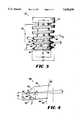
- FIG. 1is a side elevational view of an implant in accordance with the present invention designed for use as a dental implant.
- FIG. 2is a chart showing a scheme of classifying the cross sectional area of available mandibular bone into several divisions.
- FIG. 3is a side elevational schematic drawing of an implant in accordance with the present invention showing the angular and spatial relationships of the components therein.
- FIG. 4is a cross-sectional schematic drawing of a portion of a thread showing its component angular and spacial relationships.
- FIG. 5is a side elevational view of a dental implant in accordance with the present invention having a groove transverse to the thread.
- One preferred embodiment of the present inventionprovides a method for designing a skeletal implant that is adapted for implantation in a patient's bone at a predetermined site.
- predetermined siteincludes any of the possible sites in the body where a skeletal implant may be used (e.g., dental implants, etc.).
- the designerdetermines the patient's bone at the predetermined site with respect to the parameters of width, height, and elastic modulus; generating a macro-design, or large scale design, for the implant based on the measured width and height of the bone at the predetermined site and a desired biomechanical response for the implant.
- a micro-designis then determined for the implant based on the measured elastic modulus of the bone at the predetermined site whereby the implant produces a strain in the bone during functional loading of the implant that is within a predetermined range which promotes bone growth and minimizes bone resorption.
- the micro-designinvolves modifying those parameters that affect the response of the surrounding bone tissue to the implant at the cellular level.
- the designerdetermines the micro-design for the implant based on the measured elastic modulus, using strain equations to ensure that strain in the bone is kept in a range to promote bone growth and to minimize bone resorption during functional loading. This is done by identifying the forces that will be imparted by the implant to the bone at the predetermined implant site and the strain that will be experienced by the bone resulting from the forces imparted by the implant. From this information, the implant designer creates strain equations. The strain equations are applied to the implant design using the characterization parameters of the bone as input to modify the general mechanical macro-design so that the amount of strain in the implanted bone will remain within the desired range, the desired range being between about 100 and 3000 microstrain.
- strain equationsmay be applied using a computer employing any suitable numerical analysis program for optimizing complex equations of the type found in the strain equations, so that the bone contacting surface area induces strain in the desired range. While such programs are generally known to those skilled in the art, one such program is the "OPTDES" interactive computer program from Brigham Young University.
- the different types of bone commonly found in the mandible and maxillamay be assigned to groups, each group having defined average characteristics of width, height, density, and modulus of elasticity.
- the implant designeris thus able to design an implant specific for each one of the groups, the implant being optimized to produce the amount of strain that will enhance new bone growth and osteointegration and minimize resorption in a bone having the average characteristics for the group for which the implant is being designed.
- the dental surgeon employing such an implantis thereby able to characterize a patient's bone, identify the assigned group and select the implant design that corresponds to the group into which the patient's bone characterization belongs.
- Constraint valuesbased upon anatomical dimensional limitations (e.g. buccal-lingual width and crestal height) and mechanical structure of the bone, are identified. These constraints are used to define constraint equations that relate the constraints to the physical forces imparted by the implant. After the constraint equations have been defined for specific regions of the mandible and maxilla, optimization routines are used to refine the macro-design in order to create micro-design features that are specific for each type of implant. The design may be validated by any method obvious to one skilled in the art of implant design. One such method is to perform finite element analyses (FEA) on the resulting designs, thereby validating the performance of each type of dental implant under physiologic functional loading. The FEA is performed on a computer using a program (e.g. "NASTRAN”) that would be obvious to one skilled in the art.
- FEAfinite element analyses
- a preferred embodiment of the apparatus of the present inventiondesigned for use as a dental implant 10, comprises a crest portion 20 attached to a base portion 30.
- the crest portion 20provides a top surface 22 to which a prosthetic device (not shown) may be affixed.
- the crest portion 20also has a bottom surface 24 which is attached to the base portion 30.
- the base portion 30provides a means to affix the implant to the patients mandible or maxilla.
- the base portion 30comprises a substantially conical core section 32 and a thread 40 affixed to the core section 32.
- the core section 32has a crestal end 34 affixed to the bottom surface 24 of the crest portion 20 and an opposite apical end 36.
- the thread 40is continuous and has a first end 46 and a second end 48 which forms a helix around the core section 32 from the apical end 36 to the crestal end 34.
- the thread 40has a thread face 50 which is divided into an upper face 52 and a lower face 54 which are divided by the outermost end 56.
- the thread 40extends radially outward from the outer surface 38 of the core section 32 and terminates at the outermost end 56 of the thread face 50.
- the thread face 50also has an upper face ledge 42 and a lower face ledge 44.
- the apical end 36has a diameter that is smaller than the outside diameter of the thread 40 in order to allow the implant to have the self-tapping feature.
- the angle between the upper face edge 52 and the lower face edge 54approaches 180 degrees as the thread 40 nears the crestal end 34, thereby increasing the surface area in the normal plane to the occlusal forces applied to the implant 10. This is necessary in light of the fact that the greatest amount of force applied to the implant 10 is orthogonal to the occlusal plane. Therefore, normal stresses are of greatest concern, especially in the crestal regions.
- the bottom surface 100 of the base portion 30is flat in order to avoid opposing anatomical landmarks (e.g., the mandibular nerve canal as shown in FIG. 2, item 64) and to provide increased surface area in the normal plane to the applied force.
- the implant 10typically imparts most of the force that occurs as a result of functional loading in the crestal region of the bone. This induces the most strain in the crestal region, which frequently exceeds the physiologic strain levels resulting in bone resorption. Thus, it is desirable to distribute the force imparted on the crestal region of the bone by the implant 10 over a broader surface area, thereby inducing less strain in the crestal region of the implanted bone.
- the total bone contacting surfaceincreases as the thread 40 nears the crestal end 34.
- the bone contacting surface area of the threadcomprises the surfaces of the upper thread ledge 42, the lower thread ledge 44, the upper face edge 52 and the lower face edge 54.
- the radial length of the thread 40 from the outer surface 38 of the core section 32 to the outermost end 56 of the thread face 50increases as the thread 40 nears the crestal end 34. This is a result of both an increase in the angle between the upper thread face 52 and the lower thread face 54 as the thread nears the second end 48, and a narrowing of the core section 32 as it nears the crestal end 34.
- the apical end 36tends to induce less strain in the surrounding bone. If the implant 10 induces less than 100 microstrain the region of the bone near the apical end 36, new bone growth and osteointegration will occur at less than the optimal rate. Therefore, as the thread 40 nears the apical end 36, the radial length of the thread 40 from the outer surface 38 of the core section 32 to the outermost end 56 of the thread face 50 decreases. This is a result of a widening of the core section 31 near the apical end 36 and a decrease of the angle between the upper thread face edge 52 and the lower thread face edge 54. As the thread 40 nears the apical end 36, more strain is induced in the bone surrounding the apical end 36 of the implant 10. The implant 10 of the present invention thus induces strain of at least 100 microstrain in the surrounding bone, thereby promoting new bone growth and osteointegration.
- the level of strain induced in the boneis a function of the stress imparted on the bone by the implant 10.
- the stress profileIn order to maintain a uniform strain profile along the entire length of the implant 10, the stress profile must be uniform.
- Clinical experiencehas demonstrated crestal resorption surrounding root form dental implants. As has been shown in analytical studies, stresses are markedly increased in bone near the crestal regions of dental implants. This stress may be reduced in the crestal region by increasing the surface area in contact with the bone at the crestal region. In the preferred embodiment of the present invention, this area is progressively increased as the thread 40 approaches the top of the implant by using a gradually increasing thread depth.
- the preselected anglewherein the angle is a function of the vertical position of the thread along the length of the implant, between the upper face edge 52 and lower face edge 54 approach 180 degrees at a preselected rate, the rate being determined by the strain equations, as it advances to the top of the implant.
- the outside diameter of the implantmust remain constant.
- the hole drilled into the bone for placement of the implantmay have a constant inside diameter.
- a constant outside diameterwill allow the implant to have self-tapping threads which can engage the cortical plate for increased stability. This feature establishes the need for a tapered implant core.
- the tapered coreenables the thread surface area to increase gradually toward the crestal region of the implant while the outside diameter remains constant.
- the following classification of trabecular bone densityare used to provide constraints for the design: D1, D2 (coarse), D3 & D4 (fine).
- the moduli of elasticity for the trabecular bonehas been quantified for these densities.
- the modulus for D2is 67.5 MPa and the modulus for D3 and D4 is 35.5 MPa.
- the various bone shapes of the mandiblecan be characterized into six divisions. Of these divisions, divisions A 60 and B 70 and are immediate candidates in the posterior mandible for using an implant in accordance with this preferred embodiment of the present invention. Divisions C-h 76, B-W 72, C-W 74, and D 78 would be candidates for this embodiment following bone grafting procedures.
- the available height, width and length of available bonemust also be assessed for each patient. The height is measured from the crest 62 of the endentulous ridge to the opposing landmark (e.g. the maxillary sinus or mandibular canal 64).
- the widthis measured from the facial plate 66 to the lingual plate 68 at the crest. The length is limited by adjacent teeth or other implants (not shown). The outside diameter of the implant depends on the width and length of the available bone.
- the crest portion 20is incorporated into the implant design in order to provide a point of attachment for a prosthesis (not shown) and to provide a crestal bone seal.
- the diameter of the crest portionvaries according to bone type, ranging from approximately 0.4 mm larger than the outside diameter of the implant with D4-type bone to a diameter that is equal to the outside diameter in D1-type bone.
- the larger diameter in D4 boneaids in the dissipation of forces in that crestal region below the crest portion 20.
- the crest portion 20also compensates for increased bone loss that may occur during the surgical process and ensures an adequate crestal bone seal.
- bite forcesin the range of 42 to 2500 Newtons, therefore these limits are used for the force constraint used to optimize the design.
- nthe number of turns of the thread around the core section.
- DTthe diameter of the base portion from thread to thread.
- BDthe diameter of the apical end.
- TDthe diameter of the crestal end.
- Hthe height of the base portion.
- Thone-half of the width of the thread.
- Ethe modulus of elasticity for D2 or D3 or D4 trabecular bone densities.
- ⁇the shear strain induced in the bone.
- ⁇the normal strain induced in the bone.
- ⁇the angle of the thread face edges to normal.
- ⁇the angle of the outer surface of the core section to normal.
- ⁇the angle of the thread ledges to normal.
- VPoisson's ratio
- strain equationscontain each of the geometric variables used to describe the macro-design. These strain equations are employed in a computer optimization program in order to optimize the design. Once optimized in accordance with the above strain equations, the design will induce strain in the desired range in the implanted bone.
- a dental implant 105may comprise a groove 120, transverse to the thread 110, to prevent rotation of the implant 105.
Landscapes
- Health & Medical Sciences (AREA)
- Oral & Maxillofacial Surgery (AREA)
- Orthopedic Medicine & Surgery (AREA)
- Dentistry (AREA)
- Epidemiology (AREA)
- Life Sciences & Earth Sciences (AREA)
- Animal Behavior & Ethology (AREA)
- General Health & Medical Sciences (AREA)
- Public Health (AREA)
- Veterinary Medicine (AREA)
- Dental Prosthetics (AREA)
- Prostheses (AREA)
- Image Processing (AREA)
Abstract
Description
τ=Gγ
__________________________________________________________________________ Implant Outer Trabecular Bone Diameter, Implant Height, properties Axial Mechanical Density OD (mm) h (mm) E = elastic modulus (MPa) Force (Newtons) __________________________________________________________________________Division A: 3.8 < OD ≦ 4.5 12 < h ≦ 16 N/A 42-2500 D1 4.5 < OD ≦ 5.5 D2a 3.8 < OD ≦ 4.5 12 < h ≦ 16 67.5 42-2500 4.5 < OD ≦ 5.5 D2b 3.8 < OD ≦ 4.5 12 < h ≦ 16 67.5 42-2500 4.5 < OD ≦ 5.5 D3a 3.8 < OD ≦ 4.5 12 < h ≦ 16 35.5 42-2500 4.5 < OD ≦ 5.5 D3b 3.8 < OD ≦ 4.5 12 < h ≦ 16 35.5 42-2500 4.5 < OD ≦ 5.5 D4 3.8 < OD ≦ 4.5 12 < h ≦ 16 35.5 42-2500 4.5 < OD ≦ 5.5 Division B: 3.0 < OD ≦ 3.8 10 < h ≦ 16 N/A 42-2500 D1 D2a 3.0 < OD ≦ 3.8 10 < h ≦ 16 67.5 42-2500 D2b 3.0 < OD ≦ 3.8 10 < h ≦ 16 67.5 42-2500 D3a 3.0 < OD ≦ 3.8 10 < h ≦ 16 35.5 42-2500 D3b 3.0 < OD ≦ 3.8 10 < h ≦ 16 35.5 42-2500 D4 3.0 < OD ≦ 3.8 10 < h ≦ 16 35.5 42-2500 Division C-h: 3.8 < OD ≦ 4.5 10 < h ≦ 14 N/A 42-2500 D1 4.5 < OD ≦ 5.5 D2a 3.8 < OD ≦ 4.5 10 < h ≦ 14 67.5 42-2500 4.5 < OD ≦ 5.5 D2b 3.8 < OD ≦ 4.5 10 < h ≦ 14 67.5 42-2500 4.5 < OD ≦ 5.5 D3a 3.8 < OD ≦ 4.5 10 < h ≦ 14 35.5 42-2500 4.5 < OD ≦ 5.5 D3b 3.8 < OD ≦ 4.5 10 < h ≦ 14 35.5 42-2500 4.5 < OD ≦ 5.5 D4 3.8 < OD ≦ 4.5 10 < h ≦ 14 35.5 42-2500 4.5 < OD ≦ 5.5 __________________________________________________________________________
Claims (32)
Priority Applications (11)
| Application Number | Priority Date | Filing Date | Title |
|---|---|---|---|
| US08/356,597US5628630A (en) | 1994-12-15 | 1994-12-15 | Design process for skeletal implants to optimize cellular response |
| AU46008/96AAU4600896A (en) | 1994-12-15 | 1995-12-15 | Design process for skeletal implants to optimize cellular response |
| EP95944129AEP0798993A4 (en) | 1994-12-15 | 1995-12-15 | Design process for skeletal implants to optimize cellular response |
| BR9510051ABR9510051A (en) | 1994-12-15 | 1995-12-15 | Outline process for skeletal implants to optimize cellular response |
| PCT/US1995/016425WO1996018356A1 (en) | 1994-12-15 | 1995-12-15 | Design process for skeletal implants to optimize cellular response |
| CA002207950ACA2207950A1 (en) | 1994-12-15 | 1995-12-15 | Design process for skeletal implants to optimize cellular response |
| JP8519298AJPH10510737A (en) | 1994-12-15 | 1995-12-15 | How to design a skeletal implant that optimizes cellular response |
| US08/796,347US5823777A (en) | 1994-12-15 | 1997-02-07 | Dental implants to optimize cellular response |
| US08/829,764US5927979A (en) | 1994-12-15 | 1997-03-31 | Abutment-mount system for dental implants |
| MXPA/A/1997/004447AMXPA97004447A (en) | 1994-12-15 | 1997-06-16 | Design process for skeletal implants to optimize the celu response |
| US09/099,058US6083004A (en) | 1994-12-15 | 1998-06-18 | Abutment-mount system for dental implants |
Applications Claiming Priority (1)
| Application Number | Priority Date | Filing Date | Title |
|---|---|---|---|
| US08/356,597US5628630A (en) | 1994-12-15 | 1994-12-15 | Design process for skeletal implants to optimize cellular response |
Related Child Applications (2)
| Application Number | Title | Priority Date | Filing Date |
|---|---|---|---|
| US08/796,347Continuation-In-PartUS5823777A (en) | 1994-12-15 | 1997-02-07 | Dental implants to optimize cellular response |
| US08/829,764Continuation-In-PartUS5927979A (en) | 1994-12-15 | 1997-03-31 | Abutment-mount system for dental implants |
Publications (1)
| Publication Number | Publication Date |
|---|---|
| US5628630Atrue US5628630A (en) | 1997-05-13 |
Family
ID=23402119
Family Applications (2)
| Application Number | Title | Priority Date | Filing Date |
|---|---|---|---|
| US08/356,597Expired - LifetimeUS5628630A (en) | 1994-12-15 | 1994-12-15 | Design process for skeletal implants to optimize cellular response |
| US08/796,347Expired - LifetimeUS5823777A (en) | 1994-12-15 | 1997-02-07 | Dental implants to optimize cellular response |
Family Applications After (1)
| Application Number | Title | Priority Date | Filing Date |
|---|---|---|---|
| US08/796,347Expired - LifetimeUS5823777A (en) | 1994-12-15 | 1997-02-07 | Dental implants to optimize cellular response |
Country Status (7)
| Country | Link |
|---|---|
| US (2) | US5628630A (en) |
| EP (1) | EP0798993A4 (en) |
| JP (1) | JPH10510737A (en) |
| AU (1) | AU4600896A (en) |
| BR (1) | BR9510051A (en) |
| CA (1) | CA2207950A1 (en) |
| WO (1) | WO1996018356A1 (en) |
Cited By (39)
| Publication number | Priority date | Publication date | Assignee | Title |
|---|---|---|---|---|
| US6012923A (en)* | 1998-07-30 | 2000-01-11 | Sulzer Calcitek Inc. | Two-piece dental abutment with removable cuff |
| USD427683S (en)* | 1998-07-10 | 2000-07-04 | Sulzer Calcitek Inc. | Dental abutment |
| US6250922B1 (en) | 1998-07-30 | 2001-06-26 | Sulzer Dental Inc. | Two-piece dental abutment with removable cuff |
| US6273721B1 (en) | 1998-12-07 | 2001-08-14 | Maurice Valen | Dental implant |
| US6382976B1 (en) | 2001-02-05 | 2002-05-07 | Sulzer Dental Inc. | Dental implant having round bottom with fluid directing channels |
| US6402515B1 (en) | 2001-01-10 | 2002-06-11 | Sulzer Dental Inc. | Dental implant with variable profile thread |
| US6411729B1 (en)* | 1996-05-06 | 2002-06-25 | Torsana Osteoporosis Diagnostics A/S | Method of estimating skeletal status |
| US6684715B1 (en)* | 2000-09-01 | 2004-02-03 | Fmc Technologies, Inc. | Coriolis mass flowmeter with improved accuracy and simplified instrumentation |
| US20040101808A1 (en)* | 2002-11-13 | 2004-05-27 | Porter Stephan S. | Dental implant system |
| US20050147942A1 (en)* | 2001-12-21 | 2005-07-07 | Jan Hall | Method for producing a surface structure on an implant, and such an implant |
| US20050260540A1 (en)* | 2001-12-21 | 2005-11-24 | Jan Hall | Implant, and method and system for producing such an implant |
| US20070099153A1 (en)* | 2003-05-21 | 2007-05-03 | Ophir Fromovich | Condensing skeletal implant that facilitate insertions |
| WO2006050707A3 (en)* | 2004-11-09 | 2007-07-12 | Gerd Hoermansdoerfer | Screw-in member comprising a changing thread profile, and method for the production thereof |
| US20070257642A1 (en)* | 2003-06-19 | 2007-11-08 | Sean Xiao | Battery cell monitoring and balancing circuit |
| US20080025817A1 (en)* | 2004-11-09 | 2008-01-31 | Gerd Hormansdorfer | Self-Cutting Screw-In Element |
| KR100857425B1 (en) | 2007-10-22 | 2008-09-08 | 오스템임플란트 주식회사 | Dental Fixtures |
| US20090305192A1 (en)* | 2002-12-30 | 2009-12-10 | Nobel Bicare Services Ag | Implant arrangement |
| US20100188047A1 (en)* | 2003-06-19 | 2010-07-29 | O2Micro International Limited | Battery cell monitoring and balancing circuit |
| US7806693B2 (en) | 2007-04-23 | 2010-10-05 | Nobel Biocare Services Ag | Dental implant |
| US20110060560A1 (en)* | 2008-05-23 | 2011-03-10 | Salvatore Longoni | method for designing and/or selecting a device and/or material for implanting in tissues of the human or animal body and a device and/or material obtained thereby |
| US20110109269A1 (en)* | 2010-03-09 | 2011-05-12 | Guoxing Li | Circuit and method for balancing battery cells |
| US8038442B2 (en) | 2007-04-23 | 2011-10-18 | Nobel Biocare Services Ag | Dental implant and dental component connection |
| USD666295S1 (en)* | 2011-10-05 | 2012-08-28 | Hung William Y S | Dental implant |
| US20120264086A1 (en)* | 2011-04-14 | 2012-10-18 | Stig Hansson | Fixture and a fixture set |
| US20150017605A1 (en)* | 2013-07-15 | 2015-01-15 | Taiwan Shan Yin Int'l Co., Ltd. | Dental implant with high combining stability |
| US20150215696A1 (en)* | 2014-01-30 | 2015-07-30 | Cochlear Limited | Bone conduction implant |
| WO2015115692A1 (en)* | 2014-01-28 | 2015-08-06 | 주식회사 메가젠임플란트 | Fixture of dental implant |
| US9681930B2 (en) | 2014-12-15 | 2017-06-20 | Jjgc Industria E Comercio De Materiais Dentarious S/A | Implants for enhanced anchoring within bone |
| US9861455B2 (en) | 2013-07-30 | 2018-01-09 | TI Intellectual Property Inc. | Dental implant system |
| US9925024B2 (en) | 2011-06-28 | 2018-03-27 | Biomet 3I, Llc | Dental implant and abutment tools |
| USD816841S1 (en) | 2014-12-15 | 2018-05-01 | Jjgc Industria E Comercio De Materiais Dentarios S/A | Bone implant |
| US10603140B2 (en) | 2014-03-07 | 2020-03-31 | Nobel Biocare Services Ag | Dental implant |
| US10675158B2 (en) | 2015-12-16 | 2020-06-09 | Nuvasive, Inc. | Porous spinal fusion implant |
| US10898301B2 (en) | 2016-05-05 | 2021-01-26 | Jjgc Industria E Comercio De Materiais Dentarios S.A. | Prosthetic assembly and method for producing the same |
| US11058522B2 (en) | 2014-03-07 | 2021-07-13 | Nobel Biocare Services Ag | Dental implant |
| US11123173B2 (en) | 2019-09-11 | 2021-09-21 | Gary A. Zwick | Implant comprising first and second sets of pillars for attaching a tendon or a ligament to a hard tissue |
| US11213398B2 (en) | 2017-03-10 | 2022-01-04 | Gary A. Zwick | Hard-tissue implant comprising a bulk implant, a face, pillars, slots, and at least one support member |
| US11278427B2 (en) | 2018-04-10 | 2022-03-22 | Gary A. Zick, Trustee Of The Everest Trust Uta April 20, 2017 | Spinal interbody cage comprising top and bottom faces with mesh structures, pillars and slots |
| US11324606B2 (en) | 2017-03-10 | 2022-05-10 | Gary A. Zwick | Spinal interbody cage comprising a bulk interbody cage, a top face, a bottom face, pillars, and slots |
Families Citing this family (18)
| Publication number | Priority date | Publication date | Assignee | Title |
|---|---|---|---|---|
| US6217331B1 (en) | 1997-10-03 | 2001-04-17 | Implant Innovations, Inc. | Single-stage implant system |
| US6398786B1 (en) | 1997-10-09 | 2002-06-04 | Nenad Sesic | Strain-inducing conical screw for stimulating bone transplant growth |
| US6758672B2 (en) | 2000-01-18 | 2004-07-06 | Implant Innovations, Inc. | Preparation coping for creating an accurate permanent post to support a final prosthesis and method for creating the same |
| US6997711B2 (en)* | 2002-12-23 | 2006-02-14 | Robert Jeffrey Miller | Dental implant |
| KR20090016560A (en)* | 2006-05-30 | 2009-02-16 | 오름코 코포레이션 | Methods and systems for single tooth replacement in growing individuals |
| ES2363527T3 (en)* | 2006-10-11 | 2011-08-08 | Astra Tech Ab | IMPLANT. |
| US20080187886A1 (en)* | 2007-02-07 | 2008-08-07 | Robb T Tait | Dental implant with constant thread crest width |
| US7632095B2 (en) | 2007-08-13 | 2009-12-15 | Biomet 3I, Inc. | Method for forming a dental prosthesis |
| US20090298014A1 (en)* | 2008-05-28 | 2009-12-03 | Global Implant Solutions, Llc | Dental Implant |
| US8758012B2 (en)* | 2008-07-14 | 2014-06-24 | Nobel Biocare Services Ag | Compact dental implant |
| US20100015571A1 (en)* | 2008-07-15 | 2010-01-21 | Global Implant Solutions, Llc | Flexible Abutment For Use With A Dental Implant |
| EP2510901A1 (en)* | 2011-04-14 | 2012-10-17 | Astra Tech AB | Set of fixtures |
| EP2510899A1 (en) | 2011-04-14 | 2012-10-17 | Astra Tech AB | Fixture |
| EP2510900A1 (en) | 2011-04-14 | 2012-10-17 | Astra Tech AB | Fixture |
| EP2510898A1 (en) | 2011-04-14 | 2012-10-17 | Astra Tech AB | Fixture |
| TWI613992B (en) | 2016-12-28 | 2018-02-11 | 財團法人工業技術研究院 | Osteo-implant |
| CA3056220A1 (en) | 2017-03-22 | 2018-09-27 | Alan Brown | Dental implant system |
| IT202000026584A1 (en)* | 2020-11-06 | 2022-05-06 | Stefania Morici | DENTAL IMPLANT |
Citations (20)
| Publication number | Priority date | Publication date | Assignee | Title |
|---|---|---|---|---|
| US2609604A (en)* | 1949-02-14 | 1952-09-09 | Boyd F Sprague | Dental screw insert |
| US3672058A (en)* | 1969-04-18 | 1972-06-27 | Albert Jean Nikoghossian | Dental implant |
| US4431416A (en)* | 1982-04-29 | 1984-02-14 | A & L Investment Company | Endosseous dental implant system for overdenture retention, crown and bridge support |
| US4687443A (en)* | 1983-04-20 | 1987-08-18 | Boehringer Mannheim Corporation | Submergible post-type dental implant system and method of using same |
| US4997383A (en)* | 1989-06-05 | 1991-03-05 | Oratronics, Inc | Dental implant |
| US5007835A (en)* | 1989-08-17 | 1991-04-16 | Maurice Valen | Dental implant |
| US5052930A (en)* | 1989-11-22 | 1991-10-01 | Lodde Jean Pierre | Dental implant and method of implantation |
| US5074916A (en)* | 1990-05-18 | 1991-12-24 | Geltech, Inc. | Alkali-free bioactive sol-gel compositions |
| US5103806A (en)* | 1990-07-31 | 1992-04-14 | The Research Foundation Of State University Of New York | Method for the promotion of growth, ingrowth and healing of bone tissue and the prevention of osteopenia by mechanical loading of the bone tissue |
| US5108436A (en)* | 1988-09-29 | 1992-04-28 | Collagen Corporation | Implant fixation |
| US5133755A (en)* | 1986-01-28 | 1992-07-28 | Thm Biomedical, Inc. | Method and apparatus for diodegradable, osteogenic, bone graft substitute device |
| US5191880A (en)* | 1990-07-31 | 1993-03-09 | Mcleod Kenneth J | Method for the promotion of growth, ingrowth and healing of bone tissue and the prevention of osteopenia by mechanical loading of the bone tissue |
| US5204106A (en)* | 1989-04-20 | 1993-04-20 | Fbfc International S.A. | Process for restoring an osseous defect or deficiency by filling with osseous tissue |
| US5209659A (en)* | 1990-09-05 | 1993-05-11 | Impla-Med Incorporated | Method for installing a dental implant |
| US5246370A (en)* | 1992-11-27 | 1993-09-21 | Coatoam Gary W | Dental implant method |
| US5312256A (en)* | 1991-10-10 | 1994-05-17 | Gerard Scortecci | Dental implant for vertical penetration, adapted to different degrees of hardness of the bone |
| US5314475A (en)* | 1990-03-23 | 1994-05-24 | Detlev Repenning | Method for producing osteo-integrating surfaces on skeletal implants and skeletal implants with osteo-integrating surfaces |
| WO1994016636A1 (en)* | 1993-01-21 | 1994-08-04 | Huebner Randall J | Tapered bone screw with continuously varying pitch |
| US5417533A (en)* | 1990-07-13 | 1995-05-23 | National Medical Specialty, Inc. | Bone screw with improved threads |
| US5427527A (en)* | 1993-05-25 | 1995-06-27 | Vent Plant Corporation | Dental implant method of installation |
Family Cites Families (96)
| Publication number | Priority date | Publication date | Assignee | Title |
|---|---|---|---|---|
| US711324A (en)* | 1902-02-15 | 1902-10-14 | William Peter Lacy | Artificial denture. |
| US866304A (en)* | 1904-04-18 | 1907-09-17 | Finis E Roach | Removable artificial denture. |
| US2112007A (en)* | 1937-01-16 | 1938-03-22 | Pinkney B Adams | Anchoring means for false teeth |
| US2347567A (en)* | 1943-03-11 | 1944-04-25 | Edward J Kresse | Dental implant |
| GB660342A (en)* | 1949-11-07 | 1951-11-07 | Edmund Nuttall Sons & Company | Improvements in and relating to anchorage means for use in concrete and like constructions |
| BE517055A (en)* | 1952-01-21 | |||
| US2774141A (en)* | 1953-03-23 | 1956-12-18 | William T Quinn | Pontics for dental bridges |
| GB968672A (en)* | 1959-10-16 | 1964-09-02 | Baker & Finnemore Ltd | Improvements in and relating to screws with false heads for disguising their ends |
| GB937944A (en)* | 1961-08-05 | 1963-09-25 | Erich Hensel | Improvements in or relating to bolt devices |
| US3499222A (en)* | 1965-08-17 | 1970-03-10 | Leonard I Linkow | Intra-osseous pins and posts and their use and techniques thereof |
| US3435526A (en)* | 1967-02-13 | 1969-04-01 | Heli Coil Corp | Device for securing an artificial tooth to the bone structure of a human jaw |
| GB1203093A (en)* | 1967-09-15 | 1970-08-26 | Alfred Edward Edelman | Implant prostheses for dentistry. |
| US3576074A (en)* | 1968-07-15 | 1971-04-27 | Sidney D Gault | Dental endosseous root implant |
| SE332486B (en)* | 1968-12-09 | 1971-02-08 | Aga Ab | |
| SE328961B (en)* | 1970-03-25 | 1970-09-28 | Aga Ab | |
| US3849887A (en)* | 1970-06-01 | 1974-11-26 | Vitredent Corp | Dental implant |
| US3729825A (en)* | 1971-08-02 | 1973-05-01 | Oratronics Inc | Oral implant |
| US3787975A (en)* | 1972-09-18 | 1974-01-29 | M Zuest | Anchor for attaching dental partial or full artificial denture |
| US3919774A (en)* | 1973-08-28 | 1975-11-18 | Mark J Fishman | Combination endodontic apical sealer and crown post |
| US3849888A (en)* | 1973-10-19 | 1974-11-26 | Oratronics Inc | Bone adapting tissue packing post system |
| JPS5223514B2 (en)* | 1974-09-25 | 1977-06-24 | ||
| US4187609A (en)* | 1975-03-17 | 1980-02-12 | Edelman Alfred E | Submerged functional implant and method |
| CH604674A5 (en)* | 1975-07-17 | 1978-09-15 | Straumann Inst Ag | |
| DE2611744C2 (en)* | 1976-03-19 | 1982-01-28 | Werner Dipl.-Ing. 8000 Muenchen Kraus | Device for maintaining the vitality of bone tissue for endoprostheses |
| US4053982A (en)* | 1976-03-23 | 1977-10-18 | Bernard Weissman | Dental anchor |
| DE2619650C3 (en)* | 1976-05-04 | 1985-06-05 | Friedrichsfeld Gmbh, Steinzeug- Und Kunststoffwerke, 6800 Mannheim | Dental implant |
| US4109383A (en)* | 1976-06-21 | 1978-08-29 | Reed Gerald M | Dental implant bender |
| GB1565178A (en)* | 1977-02-24 | 1980-04-16 | Interfix Ltd | Bone screw |
| US4259072A (en)* | 1977-04-04 | 1981-03-31 | Kyoto Ceramic Co., Ltd. | Ceramic endosseous implant |
| US4177562A (en)* | 1977-05-02 | 1979-12-11 | Miller Alvin L | Dental implant and method of inserting the same |
| CH618870A5 (en)* | 1977-10-31 | 1980-08-29 | Straumann Inst Ag | |
| US4204321A (en)* | 1978-03-24 | 1980-05-27 | Scott Edward S | Dental post |
| US4290755A (en)* | 1979-03-05 | 1981-09-22 | Scott Edward S | Dental post and method of installing |
| CH634220A5 (en)* | 1979-11-05 | 1983-01-31 | Borle Jean Pierre | ANCHOR SCREW FOR DENTAL FILLING AND TOOL FOR FORMING A HOLLOW TO PLACE THIS SCREW. |
| CH642838A5 (en)* | 1979-11-21 | 1984-05-15 | Osteo Ag | JAW IMPLANT. |
| US4302188A (en)* | 1980-01-24 | 1981-11-24 | Bio-Dynamics, Inc. | Prosthetic dental implants |
| CH648197A5 (en)* | 1980-05-28 | 1985-03-15 | Synthes Ag | IMPLANT AND SCREW FASTENING ON ITS BONE. |
| US4406623A (en)* | 1981-01-09 | 1983-09-27 | Grafelmann Hans L | Screw-type bone implant for receiving a dental prosthesis |
| CH651747A5 (en)* | 1981-08-20 | 1985-10-15 | Straumann Inst Ag | IMPLANT FOR FASTENING AN ARTIFICIAL DENTAL REPLACEMENT. |
| SE453356B (en)* | 1981-11-16 | 1988-02-01 | Barry L Musikant | SCREW PIN FOR INSERTING IN A DENTAL ROUTE |
| US4359318A (en)* | 1981-12-18 | 1982-11-16 | Neal Gittleman | Dental implant |
| GB2117641B (en) | 1982-03-24 | 1985-03-27 | Winter Moore Peter Howard | Dental post assembly |
| US4488875A (en)* | 1982-04-29 | 1984-12-18 | A&L Investment Company | Connector for overdenture |
| US4416629A (en)* | 1982-07-06 | 1983-11-22 | Mozsary Peter G | Osseointerfaced implanted artificial tooth |
| DE3241963C1 (en)* | 1982-11-12 | 1984-04-26 | Feldmühle AG, 4000 Düsseldorf | Helical jaw implant |
| US4573922A (en)* | 1983-01-31 | 1986-03-04 | Bello Lino L | Artificial endo-osseous pillar for supporting fixed prosthetic members |
| US4552532A (en)* | 1983-12-12 | 1985-11-12 | Mozsary Peter G | Osteocorrective dentoalveolar implant system |
| DE3423752A1 (en)* | 1984-04-14 | 1985-10-24 | Hans 2800 Bremen Grafelmann | Intraossal leaf implant |
| DE3421056C2 (en)* | 1984-06-06 | 1987-04-30 | Feldmühle AG, 4000 Düsseldorf | Jaw implant with a lower part with supporting sections |
| US4645453A (en)* | 1985-09-19 | 1987-02-24 | Niznick Gerald A | Bendable adapter for dental implant |
| US4661066A (en)* | 1985-11-25 | 1987-04-28 | Linkow Leonard I | Movable plate implant |
| US4842518A (en)* | 1986-09-04 | 1989-06-27 | Vent-Plant Corporation | Submergible screw-type dental implant and method of utilization |
| US4713004A (en)* | 1986-09-04 | 1987-12-15 | Vent Plant Corporation | Submergible screw-type dental implant and method of utilization |
| US4932868A (en)* | 1986-09-04 | 1990-06-12 | Vent-Plant Corporation | Submergible screw-type dental implant and method of utilization |
| US4780080A (en)* | 1987-01-05 | 1988-10-25 | Facial Alveodental Implant Rehabilitation Inc. | Adjustable dentoalveolar implant system |
| CA1322481C (en) | 1987-01-08 | 1993-09-28 | Gerald A. Niznick | Dental implant anchor carrying plural anchoring means |
| GB2199626B (en)* | 1987-01-08 | 1991-09-04 | Core Vent Corp | Screw-type dental implant anchor |
| US5061181A (en)* | 1987-01-08 | 1991-10-29 | Core-Vent Corporation | Dental implant including plural anchoring means |
| US5078607A (en)* | 1987-01-08 | 1992-01-07 | Core-Vent Corporation | Dental implant including plural anchoring means |
| DE3708638A1 (en)* | 1987-03-17 | 1988-09-29 | Grafelmann Hans L | SELF-CUTTING SCREW-IN BONE IMPLANT FOR DENTAL PURPOSES |
| SE456216B (en)* | 1987-04-22 | 1988-09-19 | Astra Meditec Ab | TOOLS FOR A PROTEST PART |
| US4908030A (en)* | 1987-04-29 | 1990-03-13 | Vent-Plant Corporation, Inc. | Method of manufacturing synthetic bone coated surgical implants |
| US4944754A (en)* | 1987-04-29 | 1990-07-31 | Vent-Plant Corporation | Method of manufacturing synthetic bone coated surgical implants |
| US4856994A (en)* | 1988-01-25 | 1989-08-15 | Implant Innovations, Inc. | Periodontal restoration components |
| US4904187A (en)* | 1988-04-13 | 1990-02-27 | Tri-Stage, Inc. | Dental implant |
| BE1002350A3 (en)* | 1988-08-02 | 1991-01-08 | Dury Georges Emile Ladislas | IMPLANT. |
| FR2635964A1 (en)* | 1988-09-02 | 1990-03-09 | Poulmaire Francis | System which can be implanted with or without resilience, rotary device for producing the implant housing and method for using the implantable system |
| US5180303A (en)* | 1988-09-21 | 1993-01-19 | Regents Of The University Of California | Retrievable dental prothesis apparatus and method of fabrication |
| US5076788A (en)* | 1988-10-05 | 1991-12-31 | Core-Vent Corporation | Grooved, cylindrical dental implant anchoring means |
| US5022860A (en)* | 1988-12-13 | 1991-06-11 | Implant Innovations, Inc. | Ultra-slim dental implant fixtures |
| US4915628A (en)* | 1988-12-14 | 1990-04-10 | Vent-Plant Corporation, Inc. | Submergible dental implant and method of utilization |
| US5030095A (en)* | 1989-08-16 | 1991-07-09 | Niznick Gerald A | Angled abutment for endosseous implants |
| WO1991003213A1 (en)* | 1989-08-30 | 1991-03-21 | Tdk Corporation | Artificial dental root |
| US5254005A (en)* | 1989-11-14 | 1993-10-19 | Max Zuest | Dental implant system and method |
| FR2655534B1 (en)* | 1989-12-12 | 1997-10-24 | Patrick Peltier | DENTAL IMPLANT. |
| US5205746A (en)* | 1990-01-11 | 1993-04-27 | Societe De Fabrication De Materiel Orthopedique - Sofamor | Surgical implant for oral and maxillofacial implantology |
| DK0438048T3 (en)* | 1990-01-15 | 1994-06-20 | Friatec Keramik Kunststoff | dental implant |
| US5071350A (en)* | 1990-03-21 | 1991-12-10 | Core-Vent Corporation | Tiltable, adjustable, insert for a dental implant |
| US5209666A (en)* | 1990-05-15 | 1993-05-11 | Calcitek, Inc. | Endosseous implant system wtih captured screw |
| US5135395A (en)* | 1990-07-05 | 1992-08-04 | Marlin Gerald M | Implant collar and post system |
| BE1003719A3 (en)* | 1990-07-10 | 1992-05-26 | Ceka Nv | Method for achieving an implant prosthesis and parts used are hereby. |
| FR2664808A1 (en)* | 1990-07-23 | 1992-01-24 | Gersberg Eduardo | System of dental implants |
| US5116225A (en)* | 1990-10-17 | 1992-05-26 | Riera Juan C A | Angulated abutment for osseointegrated implants |
| US5195891A (en)* | 1990-12-06 | 1993-03-23 | Sulc Josef M | Adjustable dental implant system |
| SE470049B (en)* | 1991-03-01 | 1993-11-01 | Nobelpharma Ab | Device at bridge that is individually adapted to dental implants |
| SE469159B (en)* | 1991-03-27 | 1993-05-24 | Nobelpharma Ab | CYLINDER INTENDED TO BE USED IN A TEMPORARY, IMPLANT DENTAL DENTAL / DENTAL PROTEIN |
| SE9102451L (en)* | 1991-08-27 | 1992-11-16 | Nobelpharma Ab | SCREW SIZE TITAN MOUNTING FOR PERMANENT ANCHORING IN BONE TISSUE. |
| US5221204A (en)* | 1991-09-23 | 1993-06-22 | Kruger Bernard M | Dental implant product and method of making |
| JPH071133Y2 (en)* | 1991-12-06 | 1995-01-18 | 眞一 菅 | Dental implant |
| US5197881A (en)* | 1991-12-30 | 1993-03-30 | Wellesley Research Associates, Inc. | Dental implant system and apparatus |
| US5302126A (en)* | 1992-03-19 | 1994-04-12 | Park Dental Research Corp. | Dental implant with adjustable post |
| US5232364A (en)* | 1992-08-31 | 1993-08-03 | Rosen David B | Dental crown analog for orthodontic anchorage |
| US5292252A (en)* | 1992-12-14 | 1994-03-08 | Impla-Med, Inc. | Stimulator healing cap |
| US5312254A (en)* | 1993-03-26 | 1994-05-17 | Rosenlicht Joel L | Sterile application of implants in bone |
| US5269686A (en)* | 1993-05-10 | 1993-12-14 | James Robert A | Threaded drivable dental implant |
| US5302127A (en)* | 1993-06-01 | 1994-04-12 | Crisio Jr Raymond A | Dental implant stress stabilizer |
- 1994
- 1994-12-15USUS08/356,597patent/US5628630A/ennot_activeExpired - Lifetime
- 1995
- 1995-12-15WOPCT/US1995/016425patent/WO1996018356A1/ennot_activeApplication Discontinuation
- 1995-12-15AUAU46008/96Apatent/AU4600896A/ennot_activeAbandoned
- 1995-12-15CACA002207950Apatent/CA2207950A1/ennot_activeAbandoned
- 1995-12-15JPJP8519298Apatent/JPH10510737A/enactivePending
- 1995-12-15BRBR9510051Apatent/BR9510051A/ennot_activeApplication Discontinuation
- 1995-12-15EPEP95944129Apatent/EP0798993A4/ennot_activeWithdrawn
- 1997
- 1997-02-07USUS08/796,347patent/US5823777A/ennot_activeExpired - Lifetime
Patent Citations (20)
| Publication number | Priority date | Publication date | Assignee | Title |
|---|---|---|---|---|
| US2609604A (en)* | 1949-02-14 | 1952-09-09 | Boyd F Sprague | Dental screw insert |
| US3672058A (en)* | 1969-04-18 | 1972-06-27 | Albert Jean Nikoghossian | Dental implant |
| US4431416A (en)* | 1982-04-29 | 1984-02-14 | A & L Investment Company | Endosseous dental implant system for overdenture retention, crown and bridge support |
| US4687443A (en)* | 1983-04-20 | 1987-08-18 | Boehringer Mannheim Corporation | Submergible post-type dental implant system and method of using same |
| US5133755A (en)* | 1986-01-28 | 1992-07-28 | Thm Biomedical, Inc. | Method and apparatus for diodegradable, osteogenic, bone graft substitute device |
| US5108436A (en)* | 1988-09-29 | 1992-04-28 | Collagen Corporation | Implant fixation |
| US5204106A (en)* | 1989-04-20 | 1993-04-20 | Fbfc International S.A. | Process for restoring an osseous defect or deficiency by filling with osseous tissue |
| US4997383A (en)* | 1989-06-05 | 1991-03-05 | Oratronics, Inc | Dental implant |
| US5007835A (en)* | 1989-08-17 | 1991-04-16 | Maurice Valen | Dental implant |
| US5052930A (en)* | 1989-11-22 | 1991-10-01 | Lodde Jean Pierre | Dental implant and method of implantation |
| US5314475A (en)* | 1990-03-23 | 1994-05-24 | Detlev Repenning | Method for producing osteo-integrating surfaces on skeletal implants and skeletal implants with osteo-integrating surfaces |
| US5074916A (en)* | 1990-05-18 | 1991-12-24 | Geltech, Inc. | Alkali-free bioactive sol-gel compositions |
| US5417533A (en)* | 1990-07-13 | 1995-05-23 | National Medical Specialty, Inc. | Bone screw with improved threads |
| US5103806A (en)* | 1990-07-31 | 1992-04-14 | The Research Foundation Of State University Of New York | Method for the promotion of growth, ingrowth and healing of bone tissue and the prevention of osteopenia by mechanical loading of the bone tissue |
| US5191880A (en)* | 1990-07-31 | 1993-03-09 | Mcleod Kenneth J | Method for the promotion of growth, ingrowth and healing of bone tissue and the prevention of osteopenia by mechanical loading of the bone tissue |
| US5209659A (en)* | 1990-09-05 | 1993-05-11 | Impla-Med Incorporated | Method for installing a dental implant |
| US5312256A (en)* | 1991-10-10 | 1994-05-17 | Gerard Scortecci | Dental implant for vertical penetration, adapted to different degrees of hardness of the bone |
| US5246370A (en)* | 1992-11-27 | 1993-09-21 | Coatoam Gary W | Dental implant method |
| WO1994016636A1 (en)* | 1993-01-21 | 1994-08-04 | Huebner Randall J | Tapered bone screw with continuously varying pitch |
| US5427527A (en)* | 1993-05-25 | 1995-06-27 | Vent Plant Corporation | Dental implant method of installation |
Non-Patent Citations (12)
| Title |
|---|
| Brighton, Carl T., et al., The Inositol Phosphate Pathway as Mediator in the Proliferative Response of Rate Calvarial Bone Cells to Cyclical Biaxial Mechanical Strain, J. Orth. Res. , vol. 10, No. 3, pp. 385 393 (1992).* |
| Brighton, Carl T., et al., The Inositol Phosphate Pathway as Mediator in the Proliferative Response of Rate Calvarial Bone Cells to Cyclical Biaxial Mechanical Strain, J. Orth. Res., vol. 10, No. 3, pp. 385-393 (1992). |
| Cowin, S.C., et al., Candidates for the Mechanosensory System in Bone, J. Biochem. Eng. , vol. 113, pp. 191 197 (May 1991).* |
| Cowin, S.C., et al., Candidates for the Mechanosensory System in Bone, J. Biochem. Eng., vol. 113, pp. 191-197 (May 1991). |
| Ko, C.C. et al., Analysis of an Implant/Bone Interfacial Zone Using Homogenization Theory, J. Dent. Res. 71 ( AADR Abstracts ) (1992).* |
| Ko, C.C. et al., Analysis of an Implant/Bone Interfacial Zone Using Homogenization Theory, J. Dent. Res. 71 (AADR Abstracts) (1992). |
| Kohn, D.H., et al., Analysis of Implant Interfaces: Error Estimate and Effect of Fibrous Tissue, J. Dent. Res. ( AADR Abstracts ) (1992).* |
| Kohn, D.H., et al., Analysis of Implant Interfaces: Error Estimate and Effect of Fibrous Tissue, J. Dent. Res. (AADR Abstracts) (1992). |
| Misch, Carl E., Density of Bone: Effect on Treatment Plans, Surgical Approach, Healing, and Progressive Bone Loading, Int. J. Oral Implant. , vol. 6, No. 2, pp. 23 31 (1990).* |
| Misch, Carl E., Density of Bone: Effect on Treatment Plans, Surgical Approach, Healing, and Progressive Bone Loading, Int. J. Oral Implant., vol. 6, No. 2, pp. 23-31 (1990). |
| Misch, Carl E., Divisions of Available Bone in Implant Dentistry, Int. J. Oral Implant. , vol. 7, No. 1, pp. 9 17 (1990).* |
| Misch, Carl E., Divisions of Available Bone in Implant Dentistry, Int. J. Oral Implant., vol. 7, No. 1, pp. 9-17 (1990). |
Cited By (81)
| Publication number | Priority date | Publication date | Assignee | Title |
|---|---|---|---|---|
| US6411729B1 (en)* | 1996-05-06 | 2002-06-25 | Torsana Osteoporosis Diagnostics A/S | Method of estimating skeletal status |
| USD427683S (en)* | 1998-07-10 | 2000-07-04 | Sulzer Calcitek Inc. | Dental abutment |
| US6012923A (en)* | 1998-07-30 | 2000-01-11 | Sulzer Calcitek Inc. | Two-piece dental abutment with removable cuff |
| US6250922B1 (en) | 1998-07-30 | 2001-06-26 | Sulzer Dental Inc. | Two-piece dental abutment with removable cuff |
| US6273721B1 (en) | 1998-12-07 | 2001-08-14 | Maurice Valen | Dental implant |
| US6684715B1 (en)* | 2000-09-01 | 2004-02-03 | Fmc Technologies, Inc. | Coriolis mass flowmeter with improved accuracy and simplified instrumentation |
| US6402515B1 (en) | 2001-01-10 | 2002-06-11 | Sulzer Dental Inc. | Dental implant with variable profile thread |
| US6382976B1 (en) | 2001-02-05 | 2002-05-07 | Sulzer Dental Inc. | Dental implant having round bottom with fluid directing channels |
| US20050147942A1 (en)* | 2001-12-21 | 2005-07-07 | Jan Hall | Method for producing a surface structure on an implant, and such an implant |
| US9737392B2 (en) | 2001-12-21 | 2017-08-22 | Nobel Biocare Services Ag | Implant, and method and system for producing such an implant |
| US8764443B2 (en) | 2001-12-21 | 2014-07-01 | Nobel Biocare Services Ag | Method for producing a surface structure on an implant, and such an implant |
| US20050260540A1 (en)* | 2001-12-21 | 2005-11-24 | Jan Hall | Implant, and method and system for producing such an implant |
| US8827703B2 (en) | 2001-12-21 | 2014-09-09 | Nobel Biocare Services Ag | Implant, and method and system for producing such an implant |
| US9549793B2 (en) | 2002-11-13 | 2017-01-24 | Biomet 3I, Llc | Dental implant system |
| US9883927B2 (en) | 2002-11-13 | 2018-02-06 | Biomet 3I, Llc | Dental implant system |
| US20040101807A1 (en)* | 2002-11-13 | 2004-05-27 | Porter Stephan S. | Dental implant system |
| US9931182B2 (en) | 2002-11-13 | 2018-04-03 | Biomet 3I, Llc | Dental implant system |
| US7338286B2 (en) | 2002-11-13 | 2008-03-04 | Biomet 3I, Inc. | Dental implant system |
| US20080102420A1 (en)* | 2002-11-13 | 2008-05-01 | Porter Stephan S | Dental implant system |
| US8636511B2 (en) | 2002-11-13 | 2014-01-28 | Biomet 3I, Llc | Dental implant system |
| US7484959B2 (en) | 2002-11-13 | 2009-02-03 | Biomet 3I, Llc | Dental implant system |
| US20040101808A1 (en)* | 2002-11-13 | 2004-05-27 | Porter Stephan S. | Dental implant system |
| US20090305192A1 (en)* | 2002-12-30 | 2009-12-10 | Nobel Bicare Services Ag | Implant arrangement |
| US7597557B2 (en) | 2003-05-21 | 2009-10-06 | Nobel Biocare Services Ag | Condensing skeletal implant that facilitate insertions |
| US10357338B2 (en) | 2003-05-21 | 2019-07-23 | Nobel Biocare Services Ag | Condensing skeletal implant that facilitate insertions |
| EP2799031A2 (en) | 2003-05-21 | 2014-11-05 | Nobel Biocare Services AG | Condensing skeletal implant that facilitate insertion |
| US8714977B2 (en) | 2003-05-21 | 2014-05-06 | Nobel Biocare Services Ag | Condensing skeletal implant that facilitate insertions |
| US20090325126A1 (en)* | 2003-05-21 | 2009-12-31 | Ophir Fromovich | Condensing skeletal implant that facilitate insertions |
| US11147654B2 (en) | 2003-05-21 | 2021-10-19 | Nobel Biocare Services Ag | Condensing skeletal implant that facilitate insertions |
| US20100112523A1 (en)* | 2003-05-21 | 2010-05-06 | Ophir Fromovich | Condensing skeletal implant that facilitate insertions |
| EP3539504A1 (en) | 2003-05-21 | 2019-09-18 | Nobel Biocare Services AG | Condensing skeletal implant that facilitate insertion |
| US20070099153A1 (en)* | 2003-05-21 | 2007-05-03 | Ophir Fromovich | Condensing skeletal implant that facilitate insertions |
| US8197255B2 (en) | 2003-05-21 | 2012-06-12 | Nobel Biocare Services Ag | Condensing skeletal implant that facilitate insertions |
| US20100188046A1 (en)* | 2003-06-19 | 2010-07-29 | O2Micro International Limited | Battery cell monitoring and balancing circuit |
| US20070257642A1 (en)* | 2003-06-19 | 2007-11-08 | Sean Xiao | Battery cell monitoring and balancing circuit |
| US8237411B2 (en) | 2003-06-19 | 2012-08-07 | O2Micro International Limited | Battery cell monitoring and balancing circuit |
| US20100188047A1 (en)* | 2003-06-19 | 2010-07-29 | O2Micro International Limited | Battery cell monitoring and balancing circuit |
| US8004246B2 (en) | 2003-06-19 | 2011-08-23 | O2Micro International Limited | Battery cell monitoring and balancing circuit |
| US8836290B2 (en) | 2003-06-19 | 2014-09-16 | O2Micro International Limited | Battery cell monitoring and balancing circuit |
| WO2006050707A3 (en)* | 2004-11-09 | 2007-07-12 | Gerd Hoermansdoerfer | Screw-in member comprising a changing thread profile, and method for the production thereof |
| US20080025817A1 (en)* | 2004-11-09 | 2008-01-31 | Gerd Hormansdorfer | Self-Cutting Screw-In Element |
| US8864837B2 (en) | 2004-11-09 | 2014-10-21 | Gerd Hörmansdörfer | Screw-in element having changing thread profile and method for its production |
| US8206454B2 (en) | 2004-11-09 | 2012-06-26 | Hoermansdoerfer Gerd | Self-cutting screw-in element |
| US20080025819A1 (en)* | 2004-11-09 | 2008-01-31 | Gerd Hormansdorfer | Screw-In Element Having Changing Thread Profile And Method For Its Production |
| US7806693B2 (en) | 2007-04-23 | 2010-10-05 | Nobel Biocare Services Ag | Dental implant |
| US20110081626A1 (en)* | 2007-04-23 | 2011-04-07 | Nobel Biocare Services Ag | Dental implant |
| US8038442B2 (en) | 2007-04-23 | 2011-10-18 | Nobel Biocare Services Ag | Dental implant and dental component connection |
| US9452031B2 (en) | 2007-04-23 | 2016-09-27 | Nobel Biocare Services Ag | Dental implant and dental component connection |
| KR100857425B1 (en) | 2007-10-22 | 2008-09-08 | 오스템임플란트 주식회사 | Dental Fixtures |
| US8548775B2 (en) | 2008-05-23 | 2013-10-01 | Salvatore Longoni | Method for designing and/or selecting a device and/or material for implanting in tissues of the human or animal body and a device and/or material obtained thereby |
| US20110060560A1 (en)* | 2008-05-23 | 2011-03-10 | Salvatore Longoni | method for designing and/or selecting a device and/or material for implanting in tissues of the human or animal body and a device and/or material obtained thereby |
| US20110109269A1 (en)* | 2010-03-09 | 2011-05-12 | Guoxing Li | Circuit and method for balancing battery cells |
| US8872478B2 (en) | 2010-03-09 | 2014-10-28 | O2Micro Inc. | Circuit and method for balancing battery cells |
| US20120264086A1 (en)* | 2011-04-14 | 2012-10-18 | Stig Hansson | Fixture and a fixture set |
| US10952826B2 (en) | 2011-06-28 | 2021-03-23 | Biomet 3I, Llc | System and method of dental implant and interface to abutment for restoration |
| US9925024B2 (en) | 2011-06-28 | 2018-03-27 | Biomet 3I, Llc | Dental implant and abutment tools |
| USD666295S1 (en)* | 2011-10-05 | 2012-08-28 | Hung William Y S | Dental implant |
| US20150017605A1 (en)* | 2013-07-15 | 2015-01-15 | Taiwan Shan Yin Int'l Co., Ltd. | Dental implant with high combining stability |
| US9861455B2 (en) | 2013-07-30 | 2018-01-09 | TI Intellectual Property Inc. | Dental implant system |
| WO2015115692A1 (en)* | 2014-01-28 | 2015-08-06 | 주식회사 메가젠임플란트 | Fixture of dental implant |
| US20220159391A1 (en)* | 2014-01-30 | 2022-05-19 | Goran Bjorn | Bone conduction implant |
| US20150215696A1 (en)* | 2014-01-30 | 2015-07-30 | Cochlear Limited | Bone conduction implant |
| US11240613B2 (en)* | 2014-01-30 | 2022-02-01 | Cochlear Limited | Bone conduction implant |
| US10603140B2 (en) | 2014-03-07 | 2020-03-31 | Nobel Biocare Services Ag | Dental implant |
| US11058522B2 (en) | 2014-03-07 | 2021-07-13 | Nobel Biocare Services Ag | Dental implant |
| USD837378S1 (en) | 2014-12-15 | 2019-01-01 | Jjgc Industria E Comercio De Materiais Dentarios S/A | Bone implant |
| USD816841S1 (en) | 2014-12-15 | 2018-05-01 | Jjgc Industria E Comercio De Materiais Dentarios S/A | Bone implant |
| US10398533B2 (en) | 2014-12-15 | 2019-09-03 | Jjgc Industria E Comercio De Materiais Dentarios S/A | Implants for enhanced anchoring within bone |
| USD845485S1 (en) | 2014-12-15 | 2019-04-09 | Jjgc Industria E Comercio De Materiais Dentarios S/A | Bone implant |
| USD838369S1 (en) | 2014-12-15 | 2019-01-15 | Jjgc Industria E Comercio De Materiais Dentarios S/A | Bone implant |
| US9681930B2 (en) | 2014-12-15 | 2017-06-20 | Jjgc Industria E Comercio De Materiais Dentarious S/A | Implants for enhanced anchoring within bone |
| US12329653B2 (en) | 2015-12-16 | 2025-06-17 | Nuvasive Inc. | Porous spinal fusion implant |
| US10675158B2 (en) | 2015-12-16 | 2020-06-09 | Nuvasive, Inc. | Porous spinal fusion implant |
| US11660203B2 (en) | 2015-12-16 | 2023-05-30 | Nuvasive, Inc. | Porous spinal fusion implant |
| US10898301B2 (en) | 2016-05-05 | 2021-01-26 | Jjgc Industria E Comercio De Materiais Dentarios S.A. | Prosthetic assembly and method for producing the same |
| US11213398B2 (en) | 2017-03-10 | 2022-01-04 | Gary A. Zwick | Hard-tissue implant comprising a bulk implant, a face, pillars, slots, and at least one support member |
| US11324606B2 (en) | 2017-03-10 | 2022-05-10 | Gary A. Zwick | Spinal interbody cage comprising a bulk interbody cage, a top face, a bottom face, pillars, and slots |
| US11696831B2 (en) | 2017-03-10 | 2023-07-11 | Alps Holding Llc | Hard-tissue implant comprising a bulk implant, a face, pillars, slots, and at least one support member |
| US12064352B2 (en) | 2017-03-10 | 2024-08-20 | Alps Holding Llc | Hard-tissue implant comprising a bulk implant, a face, pillars, slots, and at least one support member |
| US11278427B2 (en) | 2018-04-10 | 2022-03-22 | Gary A. Zick, Trustee Of The Everest Trust Uta April 20, 2017 | Spinal interbody cage comprising top and bottom faces with mesh structures, pillars and slots |
| US11123173B2 (en) | 2019-09-11 | 2021-09-21 | Gary A. Zwick | Implant comprising first and second sets of pillars for attaching a tendon or a ligament to a hard tissue |
Also Published As
| Publication number | Publication date |
|---|---|
| EP0798993A4 (en) | 2000-03-29 |
| JPH10510737A (en) | 1998-10-20 |
| WO1996018356A1 (en) | 1996-06-20 |
| EP0798993A1 (en) | 1997-10-08 |
| US5823777A (en) | 1998-10-20 |
| CA2207950A1 (en) | 1996-06-20 |
| AU4600896A (en) | 1996-07-03 |
| MX9704447A (en) | 1998-05-31 |
| BR9510051A (en) | 1998-11-03 |
Similar Documents
| Publication | Publication Date | Title |
|---|---|---|
| US5628630A (en) | Design process for skeletal implants to optimize cellular response | |
| US5954504A (en) | Design process for skeletal implants to optimize cellular response | |
| WO1996018356A9 (en) | Design process for skeletal implants to optimize cellular response | |
| US9833300B2 (en) | Dental implant system | |
| US11006990B2 (en) | Method of making a self-cleaning self-cutting implant | |
| Misch et al. | A positive correlation between occlusal trauma and peri-implant bone loss: literature support | |
| Steigenga et al. | Dental implant design and its relationship to long-term implant success | |
| US6840770B2 (en) | Expandable polymer dental implant and method of use | |
| Misch | Bone density: a key determinant for treatment planning | |
| US8221119B1 (en) | Dental implant and method of installing the same | |
| US20130273500A1 (en) | Dental Implant and Method for Rapid Integration | |
| EP3391850B1 (en) | Fixture element | |
| WO2012059908A1 (en) | Multi-threaded dental implant | |
| KR20110122260A (en) | Fixture and its manufacturing method | |
| US6273721B1 (en) | Dental implant | |
| CN104825241A (en) | Anatomic root-shaped implant, dental prosthesis with same and method for manufacturing dental prosthesis | |
| KR100473141B1 (en) | Dental implant | |
| US7556500B2 (en) | Bone-adaptive surface structure | |
| Prakash et al. | Biomechanics in dental implants | |
| RU2178682C2 (en) | Intraosseous dental implant structure | |
| Pandey et al. | Macrodesign of dental implant–A review | |
| MXPA97004447A (en) | Design process for skeletal implants to optimize the celu response | |
| Chikr | Effects of the geometric parameters on the interfacial stresses bone/implant | |
| Torkzaban et al. | A Review of Dental Implant Treatment Planning and Implant Design Based on Bone Density | |
| WO2023152770A9 (en) | Dental implant design with enhanced surface area, torque resistance and improved stress dissipation to bone |
Legal Events
| Date | Code | Title | Description |
|---|---|---|---|
| AS | Assignment | Owner name:UNIVERSITY OF ALABAMA AT BIRMINGHAM RESEARCH FOUND Free format text:ASSIGNMENT OF ASSIGNORS INTEREST;ASSIGNORS:MISCH, CARL E.;BIDEZ, MARTHA W.;STRONG, J. TODD;REEL/FRAME:007733/0459;SIGNING DATES FROM 19951006 TO 19951012 | |
| STCF | Information on status: patent grant | Free format text:PATENTED CASE | |
| FPAY | Fee payment | Year of fee payment:4 | |
| FPAY | Fee payment | Year of fee payment:8 | |
| FPAY | Fee payment | Year of fee payment:12 | |
| AS | Assignment | Owner name:MIDCAP FINANCIAL, LLC, AS ADMINISTRATIVE AGENT, MA Free format text:SECURITY AGREEMENT;ASSIGNORS:BIOHORIZONS IMPLANT SYSTEMS, INC.;BIOLOK INTERNATIONAL INC.;ORTHOGEN CORPORATION;REEL/FRAME:022584/0216 Effective date:20090323 | |
| AS | Assignment | Owner name:MIDCAP FUNDING I, LLC, AS SUCCESSOR AGENT, MARYLAN Free format text:ASSIGNMENT AND ASSUMPTION OF SECURITY INTEREST PREVIOUSLY RECORDED AT REEL/FRAME 022584/0216 FOR PATENT SECURITY AGRM BETWEEN MIDCAP FINANCIAL, LLC AND BIOHORIZONS INPLANT SYSTEMS, INC., BIOLOK INTERNATIONAL INC. AND ORTHOGEN CORPORATION;ASSIGNOR:MIDCAP FINANCIAL, LLC, AS RETIRING AGENT;REEL/FRAME:022746/0175 Effective date:20090401 | |
| AS | Assignment | Owner name:MIDCAP FUNDING I, LLC, AS ADMINISTRATIVE AGENT,MAR Free format text:SECURITY AGREEMENT;ASSIGNORS:BIOHORIZONS IMPLANT SYSTEMS, INC.;BIOLOK INTERNATIONAL INC.;ORTHOGEN CORPORATION;REEL/FRAME:024272/0422 Effective date:20100331 | |
| SULP | Surcharge for late payment | ||
| AS | Assignment | Owner name:ORTHOGEN CORPORATION, ALABAMA Free format text:RELEASE BY SECURED PARTY;ASSIGNOR:MIDCAP FUNDING IV, LLC, AS AGENT, AS ASSIGNEE OF MIDCAP FUNDING I, LLC;REEL/FRAME:027330/0194 Effective date:20111201 Owner name:BIOLOK INTERNATIONAL INC., ALABAMA Free format text:RELEASE BY SECURED PARTY;ASSIGNOR:MIDCAP FUNDING IV, LLC, AS AGENT, AS ASSIGNEE OF MIDCAP FUNDING I, LLC;REEL/FRAME:027330/0194 Effective date:20111201 Owner name:BIOHORIZONS IMPLANT SYSTEMS, INC., ALABAMA Free format text:RELEASE BY SECURED PARTY;ASSIGNOR:MIDCAP FUNDING IV, LLC, AS AGENT, AS ASSIGNEE OF MIDCAP FUNDING I, LLC;REEL/FRAME:027330/0194 Effective date:20111201 | |
| AS | Assignment | Owner name:HENRY SCHEIN, INC., NEW YORK Free format text:PATENT SECURITY AGREEMENT;ASSIGNORS:BIOHORIZONS IMPLANT SYSTEMS, INC.;BIOHORIZONS, INC.;EVOLLUTION IP HOLDINGS, INC.;REEL/FRAME:031872/0344 Effective date:20131227 |