US5628483A - Wrist rest - Google Patents
Wrist restDownload PDFInfo
- Publication number
- US5628483A US5628483AUS08/710,045US71004596AUS5628483AUS 5628483 AUS5628483 AUS 5628483AUS 71004596 AUS71004596 AUS 71004596AUS 5628483 AUS5628483 AUS 5628483A
- Authority
- US
- United States
- Prior art keywords
- wrist rest
- layer
- support layer
- planar
- rest
- Prior art date
- Legal status (The legal status is an assumption and is not a legal conclusion. Google has not performed a legal analysis and makes no representation as to the accuracy of the status listed.)
- Expired - Lifetime
Links
Images


Classifications
- G—PHYSICS
- G06—COMPUTING OR CALCULATING; COUNTING
- G06F—ELECTRIC DIGITAL DATA PROCESSING
- G06F3/00—Input arrangements for transferring data to be processed into a form capable of being handled by the computer; Output arrangements for transferring data from processing unit to output unit, e.g. interface arrangements
- G06F3/01—Input arrangements or combined input and output arrangements for interaction between user and computer
- G06F3/03—Arrangements for converting the position or the displacement of a member into a coded form
- G06F3/033—Pointing devices displaced or positioned by the user, e.g. mice, trackballs, pens or joysticks; Accessories therefor
- G06F3/039—Accessories therefor, e.g. mouse pads
- G06F3/0395—Mouse pads
- A—HUMAN NECESSITIES
- A47—FURNITURE; DOMESTIC ARTICLES OR APPLIANCES; COFFEE MILLS; SPICE MILLS; SUCTION CLEANERS IN GENERAL
- A47B—TABLES; DESKS; OFFICE FURNITURE; CABINETS; DRAWERS; GENERAL DETAILS OF FURNITURE
- A47B21/00—Tables or desks for office equipment, e.g. typewriters, keyboards
- A47B21/03—Tables or desks for office equipment, e.g. typewriters, keyboards with substantially horizontally extensible or adjustable parts other than drawers, e.g. leaves
- A47B21/0371—Platforms for supporting wrists
- A—HUMAN NECESSITIES
- A47—FURNITURE; DOMESTIC ARTICLES OR APPLIANCES; COFFEE MILLS; SPICE MILLS; SUCTION CLEANERS IN GENERAL
- A47C—CHAIRS; SOFAS; BEDS
- A47C16/00—Stand-alone rests or supports for feet, legs, arms, back or head
- A—HUMAN NECESSITIES
- A47—FURNITURE; DOMESTIC ARTICLES OR APPLIANCES; COFFEE MILLS; SPICE MILLS; SUCTION CLEANERS IN GENERAL
- A47B—TABLES; DESKS; OFFICE FURNITURE; CABINETS; DRAWERS; GENERAL DETAILS OF FURNITURE
- A47B2200/00—General construction of tables or desks
- A47B2200/0084—Accessories for tables or desks
- A47B2200/009—Keyboards associated with mousepads
- Y—GENERAL TAGGING OF NEW TECHNOLOGICAL DEVELOPMENTS; GENERAL TAGGING OF CROSS-SECTIONAL TECHNOLOGIES SPANNING OVER SEVERAL SECTIONS OF THE IPC; TECHNICAL SUBJECTS COVERED BY FORMER USPC CROSS-REFERENCE ART COLLECTIONS [XRACs] AND DIGESTS
- Y10—TECHNICAL SUBJECTS COVERED BY FORMER USPC
- Y10S—TECHNICAL SUBJECTS COVERED BY FORMER USPC CROSS-REFERENCE ART COLLECTIONS [XRACs] AND DIGESTS
- Y10S248/00—Supports
- Y10S248/917—Video display screen support
- Y10S248/918—Ancillary device support associated with a video display screen
Definitions
- This inventionrelates generally to pads for computer users to rest their hands on while using accessories such as keyboards, trackballs, and "mice”.
- This inventionrelates specifically to pads for computer keyboard operators to rest their hands on to reduce stress on the hands, wrists, and arms, most specifically to reduce the risk of developing of carpal tunnel syndrome.
- VDTsvideo display terminals
- Repetitive stress injuries resulting from keyboard usecan take a number of forms. Steady contraction of the muscles of the upper arms and shoulder-chest region, used to hold the hands and arms outstretched over a keyboard, can lead to muscle fatigue. Muscle fatigue is seldom serious, though, and can be corrected by occasional breaks to rest the arms, and by keeping distances to work materials such as a keyboard to a minimum. Tendons seem susceptible to repetitive stress injury even more so than muscles. Most forms of tendon irritation are either the result of overuse and improper sliding between tendons and other tendons or structures nearby. The resulting inflammation and possible fraying of the tendon can result in the need for extended rest and a change in work habits.
- Tendonitis, Tenosynovitis, and Epicondylitisare all painful swellings of tendon junctions with muscles, at their point of insertion to the bone, and with their sheaths, respectively.
- a ganglionis usually a smooth round swelling or inflammation which appears near a joint, such as the wrist, or a tendon sheath; ganglions most often occur on the back of the hand.
- More serious tendon injuriesinclude ulnar nerve irritation and carpal tunnel syndrome.
- Tension on certain flexor muscles in the elbow and wristcan cause compression of the ulnar nerve at the elbow or wrist and result in reduced sensation on the ring and little fingers, as well as loss of dexterity in the hand.
- Occasionally, such nerve entrapment from repetitive overuserequires surgical release of the nerve.
- the main nerve of the handthe median nerve, passes through a narrow tunnel through the wrist formed on the top by the wrist bones and on the bottom by a ligament.
- the channelcalled the "carpal tunnel” also houses the tendons from the forearm muscles responsible for curling or closing the hand and fingers. Blood vessels in the hand also pass through the carpal tunnel.
- the present inventionprovides a wrist support pad, or wrist rest, of specially designed height for reducing strain on the wrists and hands of a keyboard operator or a similar user of computer accessories.
- the padis made to be placed in front of the keyboard or accessory being used, and may be designed to have a particular firmness for comfort.
- the bottom surfacehas no "skin", to prevent the pad from slipping, while the upper surface has a smooth covering so hands may slide around easily and comfortably.
- one embodiment of the inventionhas contours which can interlock with similar contours on an extension pad; these contours are also designed to be easily and inexpensively manufactured.
- a particular embodimentis formed as a wrist rest comprising a support layer having a first compression deflection pressure, a low friction surface layer bonded to the support layer, and a base layer bonded to the support layer and having a second compression deflection pressure, wherein the first deflection compression pressure is lower than the second compression deflection pressure.
- a wrist resthaving a length, a depth, and a height.
- the wrist restincludes a substantially rectangular support layer constructed of either an open or closed cell foam rubber.
- the support layerfurther includes a top surface and a planar bottom surface where the bottom surface is for contacting a work surface. Bonded to the top surface of the support layer is a substantially rectangular low friction surface layer having a planar top surface which is substantially parallel with the support layer when attached.
- an anchor plateis provided for attachment to the wrist rest.
- the anchor platemay be placed under a keyboard so as to hold the wrist rest in place in front of the keyboard.
- the foam rubberis selected from the group consisting of neoprene rubber, butyl rubber, and styrene-butadiene rubber (SBR).
- a wrist resthaving a substantially rectangular support layer which includes a top low friction planar surface and a bottom planar surface.
- the top and bottom planar surfacesare substantially parallel.
- the inventionfurther provides a mouse wrist rest which includes a conventional mouse pad attached to a wrist rest.
- the wrist restis constructed as previously described and allows a user's wrist to rest on the wrist rest while positioning a conventional computer mouse on the mouse pad.
- the mouse wrist restincludes an interlocking contour for attaching the mouse wrist rest to a keyboard wrist pad.
- the inventionfurther provides a platform wrist rest which includes a keyboard anchor plate (or platform) attached to a wrist rest.
- a keyboard anchor plateor platform
- This embodimentallows a keyboard to be placed on the anchor plate while the wrist rest is securely positioned in front of the keyboard.
- This embodimentallows the wrist rest to be maintained at a desired position in front of the keyboard.
- FIG. 1is a perspective view of a particular embodiment of the present invention
- FIG. 2Ais a perspective view of a particular embodiment of an extension pad contoured according to an aspect of the present invention.
- FIG. 2Bis a diagram illustrating some of the contours of the extension pad of FIG. 2A;
- FIG. 3is a top view of a particular embodiment of a wrist rest joined to the extension pad of FIG. 2, according to an aspect of the present invention
- FIG. 4is a top view of particular embodiments of a wrist rest and a mousepad contoured according to an aspect of the present invention and joined together;
- FIGS. 5A and 5Bshow a design diagram of a wrist rest and a top view of the resultant wrist rest, respectively;
- FIGS. 6A and 6Bshow a design diagram of a wrist rest with interlocking contours and a top view of the resultant wrist rest, respectively;
- FIGS. 7A and 7Bshow a design diagram of an extension pad with interlocking contours and a top view of the resultant extension pad, respectively;
- FIGS. 8A and 8Bshow a design diagram of a mousepad with interlocking contours and a top view of the resultant mousepad, respectively;
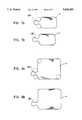
- FIG. 9shows a side view of a prior art wrist rest with a particular embodiment of a novel support pad attached on top, in front of a keyboard;
- FIG. 10shows a side view of a wrist rest with a particular embodiment of a novel support pad attached on top, in front of a keyboard;
- FIG. 11shows a side view of a particular embodiment of a wrist rest with an anchor plate according to an aspect of the present invention, in front of a keyboard;
- FIG. 12shows a side view of a particular embodiment of a wrist rest according to an aspect of the present invention, with a user's hand resting on the wrist rest and keyboard.
- FIG. 13is a perspective view of a wrist rest having a support layer and a low friction surface layer according to the present invention.
- FIG. 14is a perspective view of a mouse wrist rest according to the present invention.
- FIG. 15is a perspective view of a puzzle mouse wrist rest interlocking with a platform wrist rest according to the present invention.
- FIG. 16Is a perspective view of a notebook wrist rest according to the present invention.
- One known option to alleviate the hand and arm stress associated with keyboard activityis the use of an arm or wrist rest. Proper height of a rest as well as its comfort of use are critical to its success in preventing or alleviating keyboard repetitive stress injuries.
- Prior art keyboard reststended to be uncomfortable and to have inappropriate thicknesses or support heights.
- the wrist rest of the present inventionis designed to meet these requirements.
- FIG. 1A particular embodiment of a wrist rest according to the present invention is shown in FIG. 1, and denoted generally by reference numeral 1.
- the padis meant to lie lengthwise in front of a keyboard; it should be long enough to provide support along the entire length, including any numeric keypad, of the keyboard with which it is used. A length of about 19.5 inches is suitable for the vast majority of keyboards currently in use. Together with length, depth frames the surface of the pad. Unless tailored for a specific individual, the pad's depth should provide comfortable support for both large and small hands; about 4 inches is suitable for general use.
- a critical dimension of the padis the thickness.
- the thicknessshould be chosen so that while typing, users can comfortably rest their wrists or the heels of their hands on the pad and keep the wrist joints supported at a healthy angle so as to minimize damaging stress caused and exacerbated by compression of nerves and tendons in the carpal tunnel.
- the least amount of strainis put on the wrist joints when the hand extends level from the forearm, and within a range of about five to ten degrees in either direction; the smaller the angle, the less the strain.
- the wrist angleshould be maintained within this range, particularly within 5 degrees, as much as possible throughout the entire extent of hand movements at the keyboard.
- the proper thickness for the wrist restis thus directly tied to the height of the keyboard or other device with which the pad is to be used.
- the basic ruleis that the rest should be about equal in height to the front of the keyboard.
- a particular embodiment of the present inventionis designed to maintain the proper wrist angle with the majority of computer keyboards in commercial use, in which case thicknesses from about 1/2 inch to 1 inch can be used, with a thickness of about 5/8 inch to 7/8 inch being better, and 3/4 inch most preferred.
- the physical dimensions of the wrist restare not the only significant characteristics of the pad, however.
- the wrist restmust not only provide support at the proper height, but must also be comfortable enough that users actually do rest their wrists on the pad during substantially all keyboard use.
- the wrist rest 1 of FIG. 1has three layers.
- a low friction surface layer 10is provided to allow the hand easy travel along the length of the keyboard. By “low friction” it is meant that the skin to surface friction is low enough that the hand can slide relatively freely, without inclining users to lift their hands when moving them.
- Surface layer 10can also help prevent heat buildup and sweating, and may be soft to the touch. Materials such as nylon, polyester, and LycraTM (DuPont) are examples of materials suitable for the surface layer; these may be used in a woven cloth form and are of negligible thickness.
- a support layer 20Underneath surface layer 10 and bonded to it is a support layer 20. This layer needs to be firm enough to provide proper support for the hands, yet be supple enough to be comfortable. Foam rubber (or sponge rubber or rubber sponge) is a good material for the support layer; neoprene (wet-suit material) being particularly suitable.
- the compression-deflection pressure of support layer 20should be at least about 2 psi, and no more than 13 psi. A compression-deflection pressure under 9 psi is preferable, with the most preferable range being about 2-5 psi.
- the support layermay optionally be bonded a base layer, such as layer 30 of FIG. 1.
- This base layer 30is preferably firmer than support layer 20, and helps stabilize the pad.
- a suitable compression-deflection pressure for base layer 30is greater than about 5 psi, with a preferred range of about 5-9 psi.
- Hard materialssuch as wood or plastic may be used, but foam rubbers, and neoprene in particular, work quite well also for the base layer.
- neoprene or some other foam rubberwhich may come with a "skin” (a surface layer formed during the curing process) is used for the bottom layer of the pad, the bottom surface should be “split”, or “open”, skin (basically, skinless), and can optionally be scored, to give the pad better contact with the desktop or other work surface, so the pad slides around less. If a harder material is used for the base layer, some other contact material beneath it may be necessary to reduce sliding.
- FIG. 2Ashows an extension pad 2, with only two layers--a surface layer 10 and a support layer 20.
- the support layeris made as thick as the combined support and base layers of the example of FIG. 1.
- Surface layer 10could conceivably be left out as well, provided that the surface of the support layer was smooth and slick enough to allow a user's hand to slide freely across it.
- An interlocking contour 100is provided so that the extension pad may be joined with a wrist rest, such as in FIG. 3, which shows extension pad 2 joined to a wrist rest 3.
- the radius of curvature of the cornersis 3/4 inches; the radius of curvature of the arcs used to define interlocking contour 100 is also 3/4 inches.
- FIG. 2Billustrates in more detail interlocking contour 100.
- Contour 100is a composite of three arc segments from circles 1000, 2000, and 3000.
- the radius of curvature of each of these circlesis about 3/4 inches.
- Circle 1000joins the side of pad 2 at a point indicated by segment A--A, therefore having its center 3/4" left of that point of joinder.
- Circle 2000has its center about 13/16 inches left of and about 113/16 inches above the center of circle 1000.
- Circle 3000has its center about 23/8 inches directly above the center of circle 1000. These distances are approximate; the circles should meet tangentially at the points indicated by segments B--B and C--C.
- An arc segment 1100extends around the lesser portion of circle 1000 from A--A to B--B, where it joins an arc segment 2100.
- Arc segment 2100extends around the greater portion of circle 2000 from B--B to C--C, where it joins an arc segment 3100, which extends around the lesser portion of circle 3000 from C--C to D--D.
- Arc Segments 1100, 2100 and 3100together form interlocking contour 100.
- An extension padwill be particularly useful if the keyboard is exceptionally wide, or if an auxiliary device such as a track ball is positioned next to the keyboard; a typical width for such an extension pad is around six inches.
- the interlocking contourshelp keep the extension pad in place, and interlocking contours can also be used to join a wrist rest to a mousepad, as in FIG. 4, which shows wrist rest 3 joined to mousepad 4. Such interlocking keeps the mousepad secure and provides continuous support for the wrist.
- One advantage of such interlocking pads over a wrist rest formed integrally with a mousepadis that with the interlock feature the same wrist rest may be used with either a right-handed or left-handed mousepad simply by being rotated 180° with the surface remaining face up.
- FIGS. 5A and 5Bshow a design diagram of an wrist rest 1 with rounded corners 50, and a top view of the resultant wrist rest, respectively.
- the radius of curvature of the cornersis 3/4 inches.
- FIGS. 6A and 6Bshow a design diagram of an wrist rest with an interlocking contour and a top view of the resultant wrist rest, respectively. Again, the radius of curvature of the corners is 3/4 inches; the radius of curvature of arcs used to define an interlocking contour 101 is also 3/4 inches. It is formed in the same general manner as contour 100, described above, but it extends into the pad as a hole rather than out from it as a projection. FIGS.
- FIG. 7A, 7B and 8A, 8Bshow similar diagrams for an extension pad and a mousepad, respectively. Having the accessory pads interlock with the wrist rest assures a close fit and an even surface so the user's hand may slide freely across from one to another.
- the formation of the interlocking contourshas high aesthetic appeal as well as having manufacturing benefits such as about 15 percent less wasted material and more compact shipping.
- the curvesmay be cut into neoprene by using a swing arm clicker press, a travelling head press, or a full head press, with steel rule dies.
- FIG. 9shows a keyboard 200 with a prior art wrist rest 300, many of which are about 1/2 inch high.
- a support pad 400is glued onto the wrist rest 300; this may be done with an adhesive layer on the bottom of the support pad.
- Support pad 400may extend around the front of wrist rest 300 as shown here, or it may cover only the top surface. It is manufactured in the same manner as the previously described wrist rest of the present invention, but it is generally made without a base layer and has a total height of about 1/4 inch. This 1/4 inch height plus the 1/2 inch height of the prior wrist rest combine to make a support surface 3/4 inch high, ideal for most keyboards.
- FIG. 10shows a keyboard and a support pad 400 attached to another wrist rest 500, which has a recurve portion in front.
- FIG. 11shows a keyboard 200, and in front and underneath it a wrist rest 5.
- Wrist rest 5has a surface layer 10, a support layer 20, a base layer 30, and an anchor plate 40.
- Anchor plate 40slides under the keyboard and allows the wrist rest to be positioned in front of a keyboard with no support directly underneath the wrist rest.
- FIG. 12shows a wrist rest 1 in front of a keyboard 200. Also shown is a user's hand 600 in normal position on the wrist rest and keyboard. The user's wrist 610 is supported nearly level, with almost no deflection angle.
- Typical problemsinclude lingering odor after manufacture, and warpage resulting from different layers being bonded together.
- Neopreneinevitably has basically no odor, a distinct advantage over most other foam rubbers, which retain a strong odor.
- an odormay be caused by the glue employed to bond layers, in which case aging the wrist rest in the sun may help reduce this glue odor.
- One way of reducing or solving the warpage problemis to heat age the materials before manufacture so there will be no differential shrinking of different layers during manufacture.
- An alternative methodis simply to employ materials with the same heat shrinkage characteristics.
- wrist rests according to the present inventioncan be constructed using only a support layer and a low friction surface layer.
- a wrist rest 210 having only a support layer 212 and a low friction surface layer 214is shown in FIG. 13.
- the support layer 212can be constructed of foam rubber.
- rubbercan be classified as natural or synthetic, and can alternately be classified as being cellular, i.e. foamed, or non-cellular. If in cellular form, rubber can be further classified as open-celled or closed-celled. Open-celled generally means that the cells are interconnected in such a manner that gas can penetrate from one cell to another, such as sponge rubber. For closed-celled rubbers, the cells are discrete and independent of the other cells, such as in neoprene rubber.
- the support layer 212can be constructed of any type of rubber, and is preferably made from rubber in cellular form, either open-celled or closed celled.
- Preferable rubbersinclude neoprene (or polycholoroprene), styrene-butadiene rubbers (SBR), butyl rubber, and the like.
- the support layer 212has a planar bottom surface 216 for contacting a work surface.
- the low friction surface layer 214is bonded to a top surface 218 of the support layer 212 and has a planar top surface 220.
- the support layer 212 and low friction surface layer 214are joined so that the planar bottom surface 216 of the support layer 212 and the top planar surface 220 of the low friction surface layer 214 are substantially parallel.
- the height of the wrist rest 210is preferably the same height as the wrist rest 1 in FIG. 1.
- the low friction surface layer 214can be omitted and the top surface 218 of the support layer 212 can made planar and substantially parallel with the planar bottom surface 216.
- a mouse wrist rest 222is shown in FIG. 14 along with a conventional computer mouse 223.
- the mouse wrist rest 222includes a mouse pad 224 and a wrist rest 226.
- the mouse pad 224can be a commercially available conventional mouse pad, available from commercial suppliers such as Fry's Electronics, Palo Alto, Calif. and Wal-Mart.
- the mouse pad 224can be constructed of closed cell rubber, polycarbonate plastic such as LEXAN® (General Electric Plastics), other plastics and the like.
- the wrist rest 226can be constructed essentially identical to the wrist rests 1 or 210 as previously described herein, and sized appropriately in width to match the width of the mouse pad 224.
- the wrist rest 226is securely attached to the mouse pad 224, preferably by bonding. The bond should be strong enough to maintain attachment of the wrist rest 226 and mouse pad 224 during normal use.
- a puzzle mouse wrist rest 228is shown in FIG. 15.
- the puzzle mouse wrist rest 228is essentially identical to the wrist rest 226 as described in connection with FIG. 14 except that the puzzle mouse wrist rest 228 has an interlocking connection 230.
- the interlocking connection 230is used to interlock the puzzle mouse wrist rest 228 to a keyboard wrist rest 232.
- the keyboard wrist rest 232can be essentially identical to the wrist rest shown in FIG. 11, or can be the wrist rest 210 of FIG. 13 attached to a keyboard anchor plate, or can be a single wrist rest essentially identical to wrist rests 1 or 210 as previously described. As shown in FIG. 15, the keyboard wrist rest 232 is a "platform" style wrist rest as described in connection with FIG. 11.
- the keyboard wrist rest 232has a support layer 234 and a low friction surface layer 236, and is constructed essentially identical to the wrist rest 210 described in FIG. 13. Attached to the support layer 234 is an anchor plate (not shown) for placement under a keyboard 238.
- the anchor plateserves to anchor the support layer 234 is proper alignment with the keyboard 238.
- the anchoris constructed of a rigid material, and is preferably made of metal, aluminum, plastic, rubber, composites, and the like.
- the anchorcan be coated with a protective material to prevent the anchor from scratching a desk or other office equipment.
- the anchorwill be coated with neoprene rubber.
- the interlocking connection 230can be a male connection as shown in FIG. 15, or can alternatively be a female connection which interlocks with a corresponding male interlocking connector on the keyboard wrist rest 232.
- the interlocking connection 230is preferably formed as previously described in connection with FIGS. 2A and 2B.
- a mouse 240can be positioned on a mousepad 242 by a user while the puzzle mouse wrist rest 228 is prevented from sliding by the keyboard wrist rest 232.
- the useris further able to rest his or her wrist while typing at the keyboard 238 or while positioning the mouse 240.
- a notebook wrist rest 250is shown in FIG. 16.
- the notebook wrist rest 250is preferably used with a notebook computer 252.
- the notebook wrist rest 250includes an anchor plate 254 and a wrist rest 256.
- the notebook wrist rest 250can be configured to be essential identical to the wrist rest described in connection with FIG. 11, except for being sized to the dimensions of the notebook computer 252.
- the wrist rest 256includes a low friction layer 258, a support layer 260, and a base layer (not shown) below the support layer 260.
- the wrist restcan be constructed using only the support layer 260 and the low friction layer 258 as previously described.
- the anchor plate 254can be constructed essentially identical to the anchor plate described in connection with FIG. 11. In another aspect, the anchor plate 254 will preferably be sandwiched between layers of neoprene rubber 262 which serve to prevent the anchor plate 254 from scratching a desktop or other work surface.
Landscapes
- Engineering & Computer Science (AREA)
- General Engineering & Computer Science (AREA)
- Theoretical Computer Science (AREA)
- Human Computer Interaction (AREA)
- Physics & Mathematics (AREA)
- General Physics & Mathematics (AREA)
- Input From Keyboards Or The Like (AREA)
- Position Input By Displaying (AREA)
Abstract
Description
Claims (20)
Priority Applications (1)
| Application Number | Priority Date | Filing Date | Title |
|---|---|---|---|
| US08/710,045US5628483A (en) | 1991-04-24 | 1996-09-10 | Wrist rest |
Applications Claiming Priority (4)
| Application Number | Priority Date | Filing Date | Title |
|---|---|---|---|
| US07/690,742US5197699A (en) | 1991-04-24 | 1991-04-24 | Wrist rest |
| US08/006,225US5358203A (en) | 1991-04-24 | 1993-01-19 | Wrist rest |
| US25558194A | 1994-06-08 | 1994-06-08 | |
| US08/710,045US5628483A (en) | 1991-04-24 | 1996-09-10 | Wrist rest |
Related Parent Applications (1)
| Application Number | Title | Priority Date | Filing Date |
|---|---|---|---|
| US25558194AContinuation | 1991-04-24 | 1994-06-08 |
Publications (1)
| Publication Number | Publication Date |
|---|---|
| US5628483Atrue US5628483A (en) | 1997-05-13 |
Family
ID=27358071
Family Applications (1)
| Application Number | Title | Priority Date | Filing Date |
|---|---|---|---|
| US08/710,045Expired - LifetimeUS5628483A (en) | 1991-04-24 | 1996-09-10 | Wrist rest |
Country Status (1)
| Country | Link |
|---|---|
| US (1) | US5628483A (en) |
Cited By (42)
| Publication number | Priority date | Publication date | Assignee | Title |
|---|---|---|---|---|
| WO1998028222A1 (en)* | 1996-12-20 | 1998-07-02 | The Mousebar Company | Computer mouse operation pad and forearm support assembly |
| USD395876S (en) | 1997-05-13 | 1998-07-07 | Afarian Diran A | Mouse pad with two interlocking pieces |
| US5826841A (en)* | 1997-03-18 | 1998-10-27 | Lavore; Joseph S. | Therapeutic elbow support system |
| WO1998053721A1 (en)* | 1997-05-30 | 1998-12-03 | Haworth, Inc. | Keyboard support with multi-positional mouse pad |
| US5845884A (en)* | 1996-07-10 | 1998-12-08 | Terbrack; William H. | Ergonomic tower support device for using data entry systems |
| EP0884692A1 (en)* | 1997-06-13 | 1998-12-16 | Listawood Limited | Mouse mat |
| USD410453S (en)* | 1998-09-30 | 1999-06-01 | Work-Rite Ergonomics Accessories, Inc. | Keyboard support having movable mouse extension |
| US6000665A (en)* | 1998-05-15 | 1999-12-14 | Clementson; David | Support device and method for use with a miniature electronic device |
| US6003446A (en)* | 1998-12-28 | 1999-12-21 | Leibowitz; Marc | Keyboard lap table |
| US6082682A (en)* | 1998-02-05 | 2000-07-04 | So; Vincent | Mouse user wrist support |
| US6131862A (en)* | 1997-08-12 | 2000-10-17 | Gruenenfelder; Marc A. | Ergonomic support system |
| US6147864A (en)* | 1999-03-03 | 2000-11-14 | Gateway 2000, Inc. | Apparatus for attaching a remote control device |
| US6244547B1 (en) | 2000-02-01 | 2001-06-12 | Haworth, Inc. | Keyboard tray with adjustable wrist support |
| US6244546B1 (en) | 1998-11-02 | 2001-06-12 | Orance Plamondon | Cantilevered sliding elbow rest |
| US6276647B1 (en)* | 1999-06-21 | 2001-08-21 | Robin D. Stopper | Wrist and hand support apparatus for elevating the hand and wrist |
| US6279859B2 (en)* | 1998-10-16 | 2001-08-28 | Haworth, Inc. | Keyboard pad with reversible mouse pad |
| US6332533B1 (en) | 2000-08-29 | 2001-12-25 | H.H.H. Incorprorated | Media holder mouse pad |
| US6369795B1 (en)* | 1998-04-01 | 2002-04-09 | Siemens Information And Communication Mobile Llc | Mousepad telephone |
| US6402101B1 (en)* | 1996-05-30 | 2002-06-11 | Trico Sports, Inc. | Formable mouse pad |
| US6452791B2 (en)* | 1998-10-03 | 2002-09-17 | Stanley A. Kim | Wrist support |
| US6497391B1 (en) | 1999-08-07 | 2002-12-24 | Work-Rite Ergonomic Accessories, Inc. | Personal computer keyboard and mouse support having moveable mouse extension |
| US6533479B2 (en) | 2000-12-21 | 2003-03-18 | Pent Products | Integral keyboard/tray/wrist rest |
| US6543949B1 (en) | 2000-03-23 | 2003-04-08 | Eugene B. Ritchey | Keyboard support apparatus |
| US20030170062A1 (en)* | 2000-12-21 | 2003-09-11 | Kochanski Walter T. | Mountable integral keyboard |
| US6747634B1 (en)* | 2000-09-19 | 2004-06-08 | Tai-Her Yang | Assembly of mouse with trackball device permitting selection of the position of a chosen receiver |
| US6749158B2 (en) | 1998-08-07 | 2004-06-15 | Work-Rite Ergonomic Accessories, Inc. | Computer keyboard and mouse support having moveable mouse extension |
| USD508918S1 (en) | 2004-04-06 | 2005-08-30 | Eugene B. Ritchey | Keyboard support |
| US20050218272A1 (en)* | 2004-04-06 | 2005-10-06 | Ritchey Eugene B | Keyboard support device and method |
| US7086634B1 (en) | 2000-09-20 | 2006-08-08 | 3M Innovative Properties Company | Adjustable keyboard tray |
| US7157633B1 (en) | 2004-03-02 | 2007-01-02 | Richard Martin Kopesec | Simulated stringed instrument practice device |
| US20070235040A1 (en)* | 2006-04-07 | 2007-10-11 | Eduardo Salcedo | Laryngoscope Dental Protection Device |
| US20080111792A1 (en)* | 2006-11-15 | 2008-05-15 | Acco Brands Usa Llc | Input device including wireless and wired modes |
| US20080117173A1 (en)* | 2006-11-15 | 2008-05-22 | Acco Brands Usa Llc | Keyboard and handheld input device system |
| EP1818787A3 (en)* | 2006-02-13 | 2009-01-07 | Aurelio Lambertini | Ergonomic wrist rest, particularlly for using computer keybboards and mice |
| US20100230556A1 (en)* | 2009-03-10 | 2010-09-16 | Gitan Mayer | Wrist saver |
| US8136459B2 (en)* | 2010-08-08 | 2012-03-20 | Oakwood School | Desk with book holder |
| US20130017736A1 (en)* | 2011-07-15 | 2013-01-17 | Wistron Corporation | Power adapter device provided with a mouse pad |
| US20190082825A1 (en)* | 2017-09-18 | 2019-03-21 | Noel Webb | Pad for Supporting a User's Wrists, Lower Arms, and Keyboard While Typing |
| USD923635S1 (en)* | 2018-09-17 | 2021-06-29 | Noel Webb | Keyboard wrist pad |
| US20230189984A1 (en)* | 2021-12-21 | 2023-06-22 | Innovation Parke Llc | Dual surface and reversible ergonomic computer accessory with interlocking panels |
| USD1024088S1 (en) | 2023-06-28 | 2024-04-23 | Jia Zhang | Keyboard wrist rest |
| USD1095542S1 (en)* | 2025-03-11 | 2025-09-30 | Jia Zhang | Keyboard wrist rest |
Citations (17)
| Publication number | Priority date | Publication date | Assignee | Title |
|---|---|---|---|---|
| FR2148853A5 (en)* | 1971-08-04 | 1973-03-23 | Chomarat & Cie | Foam cored head rests - made by assembling complementary moulding with vacuum formed covers to avoid tailoring |
| US4481556A (en)* | 1980-04-04 | 1984-11-06 | Joseph J. Berke | Computer terminal support and hand rest |
| US4482063A (en)* | 1980-04-04 | 1984-11-13 | Joseph J. Berke | Computer terminal support and hand rest |
| US4545554A (en)* | 1981-08-31 | 1985-10-08 | Latino Richard M | Wrist support for use with an office machine having a keyboard |
| US4621781A (en)* | 1985-05-16 | 1986-11-11 | Marvel Metal Products Co. | Ergonomic forearm rest for use with keyboards |
| US4709972A (en)* | 1986-08-27 | 1987-12-01 | Eastman Kodak Company | Keyboard cabinet with sliding tray |
| US4973176A (en)* | 1988-12-20 | 1990-11-27 | Dietrich Jeffrey A | Appendage rest |
| US5022622A (en)* | 1990-01-12 | 1991-06-11 | Schaevitz Lester P | Support for the body of a worker |
| US5056743A (en)* | 1990-08-17 | 1991-10-15 | Zwar Kurt F | Arm support system |
| US5125606A (en)* | 1991-06-12 | 1992-06-30 | Wrist-Eze Products, Inc. | Wrist support for computer keyboard |
| US5131614A (en)* | 1990-10-01 | 1992-07-21 | Garcia James M | Wrist rest support for a computer user |
| US5163646A (en)* | 1990-09-18 | 1992-11-17 | Bernard Engelhardt | Wrist support arrangement for use with stand-alone keyboard |
| US5165630A (en)* | 1991-08-06 | 1992-11-24 | Connor Martin D | Wrist protector |
| US5170971A (en)* | 1991-05-28 | 1992-12-15 | Opi Products, Inc. | Table top mountable wrist supporter |
| US5197699A (en)* | 1991-04-24 | 1993-03-30 | Silicon Sports | Wrist rest |
| US5228655A (en)* | 1990-10-01 | 1993-07-20 | Garcia James M | Wrist rest support for a computer user |
| US5320317A (en)* | 1990-09-21 | 1994-06-14 | Hyatt Robert G | Wrist and forearm support apparatus |
- 1996
- 1996-09-10USUS08/710,045patent/US5628483A/ennot_activeExpired - Lifetime
Patent Citations (19)
| Publication number | Priority date | Publication date | Assignee | Title |
|---|---|---|---|---|
| FR2148853A5 (en)* | 1971-08-04 | 1973-03-23 | Chomarat & Cie | Foam cored head rests - made by assembling complementary moulding with vacuum formed covers to avoid tailoring |
| US4481556A (en)* | 1980-04-04 | 1984-11-06 | Joseph J. Berke | Computer terminal support and hand rest |
| US4482063A (en)* | 1980-04-04 | 1984-11-13 | Joseph J. Berke | Computer terminal support and hand rest |
| US4545554A (en)* | 1981-08-31 | 1985-10-08 | Latino Richard M | Wrist support for use with an office machine having a keyboard |
| US4621781A (en)* | 1985-05-16 | 1986-11-11 | Marvel Metal Products Co. | Ergonomic forearm rest for use with keyboards |
| US4709972A (en)* | 1986-08-27 | 1987-12-01 | Eastman Kodak Company | Keyboard cabinet with sliding tray |
| US4973176A (en)* | 1988-12-20 | 1990-11-27 | Dietrich Jeffrey A | Appendage rest |
| US5022622A (en)* | 1990-01-12 | 1991-06-11 | Schaevitz Lester P | Support for the body of a worker |
| US5056743A (en)* | 1990-08-17 | 1991-10-15 | Zwar Kurt F | Arm support system |
| US5163646A (en)* | 1990-09-18 | 1992-11-17 | Bernard Engelhardt | Wrist support arrangement for use with stand-alone keyboard |
| US5320317A (en)* | 1990-09-21 | 1994-06-14 | Hyatt Robert G | Wrist and forearm support apparatus |
| US5131614A (en)* | 1990-10-01 | 1992-07-21 | Garcia James M | Wrist rest support for a computer user |
| US5228655A (en)* | 1990-10-01 | 1993-07-20 | Garcia James M | Wrist rest support for a computer user |
| US5197699A (en)* | 1991-04-24 | 1993-03-30 | Silicon Sports | Wrist rest |
| US5358203A (en)* | 1991-04-24 | 1994-10-25 | Silicon Sports, Inc. | Wrist rest |
| US5451020A (en)* | 1991-04-24 | 1995-09-19 | Silicon Sports, Inc. | Wrist rest |
| US5170971A (en)* | 1991-05-28 | 1992-12-15 | Opi Products, Inc. | Table top mountable wrist supporter |
| US5125606A (en)* | 1991-06-12 | 1992-06-30 | Wrist-Eze Products, Inc. | Wrist support for computer keyboard |
| US5165630A (en)* | 1991-08-06 | 1992-11-24 | Connor Martin D | Wrist protector |
Non-Patent Citations (20)
| Title |
|---|
| Brochure for "Curtis Wrist Rest," Curtis Manufacturing, Inc. |
| Brochure for "Key Pads," American Covers Inc. |
| Brochure for "Keyboard Buddy," Computer Expressions. |
| Brochure for "Keyboard Wrist Rest," Alimed, Inc., 1990, Product #1011. |
| Brochure for "Keyboard Wrist Rest," Global Computer Supplies. |
| Brochure for "Wrist Pad Plus," Marty's Computer Workshop. |
| Brochure for "Wrist Pro," Wrist Pro. |
| Brochure for "Wrist Supports," M&M Industries. |
| Brochure for "Wristonics," Marcus Franklin & Associates. |
| Brochure for "Wrist-Stop," George McDonald Engineering Co., Inc., 1990. |
| Brochure for Curtis Wrist Rest, Curtis Manufacturing, Inc.* |
| Brochure for Key Pads, American Covers Inc.* |
| Brochure for Keyboard Buddy, Computer Expressions.* |
| Brochure for Keyboard Wrist Rest, Alimed, Inc., 1990, Product 1011.* |
| Brochure for Keyboard Wrist Rest, Global Computer Supplies.* |
| Brochure for Wrist Pad Plus, Marty s Computer Workshop.* |
| Brochure for Wrist Pro, Wrist Pro.* |
| Brochure for Wrist Stop, George McDonald Engineering Co., Inc., 1990.* |
| Brochure for Wrist Supports, M&M Industries.* |
| Brochure for Wristonics, Marcus Franklin & Associates.* |
Cited By (50)
| Publication number | Priority date | Publication date | Assignee | Title |
|---|---|---|---|---|
| US6402101B1 (en)* | 1996-05-30 | 2002-06-11 | Trico Sports, Inc. | Formable mouse pad |
| US5845884A (en)* | 1996-07-10 | 1998-12-08 | Terbrack; William H. | Ergonomic tower support device for using data entry systems |
| WO1998028222A1 (en)* | 1996-12-20 | 1998-07-02 | The Mousebar Company | Computer mouse operation pad and forearm support assembly |
| US5826841A (en)* | 1997-03-18 | 1998-10-27 | Lavore; Joseph S. | Therapeutic elbow support system |
| USD395876S (en) | 1997-05-13 | 1998-07-07 | Afarian Diran A | Mouse pad with two interlocking pieces |
| WO1998053721A1 (en)* | 1997-05-30 | 1998-12-03 | Haworth, Inc. | Keyboard support with multi-positional mouse pad |
| US5927662A (en)* | 1997-05-30 | 1999-07-27 | Haworth, Inc. | Keyboard support with multi-positional mouse pad |
| EP0884692A1 (en)* | 1997-06-13 | 1998-12-16 | Listawood Limited | Mouse mat |
| US6131862A (en)* | 1997-08-12 | 2000-10-17 | Gruenenfelder; Marc A. | Ergonomic support system |
| US6082682A (en)* | 1998-02-05 | 2000-07-04 | So; Vincent | Mouse user wrist support |
| US6369795B1 (en)* | 1998-04-01 | 2002-04-09 | Siemens Information And Communication Mobile Llc | Mousepad telephone |
| US6000665A (en)* | 1998-05-15 | 1999-12-14 | Clementson; David | Support device and method for use with a miniature electronic device |
| US6749158B2 (en) | 1998-08-07 | 2004-06-15 | Work-Rite Ergonomic Accessories, Inc. | Computer keyboard and mouse support having moveable mouse extension |
| USD410453S (en)* | 1998-09-30 | 1999-06-01 | Work-Rite Ergonomics Accessories, Inc. | Keyboard support having movable mouse extension |
| US6887005B2 (en)* | 1998-10-03 | 2005-05-03 | Stanley A. Kim | Notebook computer with wrist support |
| US6452791B2 (en)* | 1998-10-03 | 2002-09-17 | Stanley A. Kim | Wrist support |
| US20040062589A1 (en)* | 1998-10-03 | 2004-04-01 | Kim Stanley A. | Notebook computer with wrist support |
| US6279859B2 (en)* | 1998-10-16 | 2001-08-28 | Haworth, Inc. | Keyboard pad with reversible mouse pad |
| US6244546B1 (en) | 1998-11-02 | 2001-06-12 | Orance Plamondon | Cantilevered sliding elbow rest |
| US6003446A (en)* | 1998-12-28 | 1999-12-21 | Leibowitz; Marc | Keyboard lap table |
| US6147864A (en)* | 1999-03-03 | 2000-11-14 | Gateway 2000, Inc. | Apparatus for attaching a remote control device |
| US6276647B1 (en)* | 1999-06-21 | 2001-08-21 | Robin D. Stopper | Wrist and hand support apparatus for elevating the hand and wrist |
| US6497391B1 (en) | 1999-08-07 | 2002-12-24 | Work-Rite Ergonomic Accessories, Inc. | Personal computer keyboard and mouse support having moveable mouse extension |
| US6244547B1 (en) | 2000-02-01 | 2001-06-12 | Haworth, Inc. | Keyboard tray with adjustable wrist support |
| US6543949B1 (en) | 2000-03-23 | 2003-04-08 | Eugene B. Ritchey | Keyboard support apparatus |
| US6332533B1 (en) | 2000-08-29 | 2001-12-25 | H.H.H. Incorprorated | Media holder mouse pad |
| US6747634B1 (en)* | 2000-09-19 | 2004-06-08 | Tai-Her Yang | Assembly of mouse with trackball device permitting selection of the position of a chosen receiver |
| US7086634B1 (en) | 2000-09-20 | 2006-08-08 | 3M Innovative Properties Company | Adjustable keyboard tray |
| US20030170062A1 (en)* | 2000-12-21 | 2003-09-11 | Kochanski Walter T. | Mountable integral keyboard |
| US6533479B2 (en) | 2000-12-21 | 2003-03-18 | Pent Products | Integral keyboard/tray/wrist rest |
| US7157633B1 (en) | 2004-03-02 | 2007-01-02 | Richard Martin Kopesec | Simulated stringed instrument practice device |
| USD508918S1 (en) | 2004-04-06 | 2005-08-30 | Eugene B. Ritchey | Keyboard support |
| US20050218272A1 (en)* | 2004-04-06 | 2005-10-06 | Ritchey Eugene B | Keyboard support device and method |
| US7108234B2 (en) | 2004-04-06 | 2006-09-19 | Ritchey Eugene B | Keyboard support device and method |
| EP1818787A3 (en)* | 2006-02-13 | 2009-01-07 | Aurelio Lambertini | Ergonomic wrist rest, particularlly for using computer keybboards and mice |
| US20070235040A1 (en)* | 2006-04-07 | 2007-10-11 | Eduardo Salcedo | Laryngoscope Dental Protection Device |
| US8235892B2 (en)* | 2006-04-07 | 2012-08-07 | Eduardo Salcedo | Laryngoscope dental protection device |
| US20080111792A1 (en)* | 2006-11-15 | 2008-05-15 | Acco Brands Usa Llc | Input device including wireless and wired modes |
| US20080117173A1 (en)* | 2006-11-15 | 2008-05-22 | Acco Brands Usa Llc | Keyboard and handheld input device system |
| US20100230556A1 (en)* | 2009-03-10 | 2010-09-16 | Gitan Mayer | Wrist saver |
| US8136459B2 (en)* | 2010-08-08 | 2012-03-20 | Oakwood School | Desk with book holder |
| US20130017736A1 (en)* | 2011-07-15 | 2013-01-17 | Wistron Corporation | Power adapter device provided with a mouse pad |
| US8797725B2 (en)* | 2011-07-15 | 2014-08-05 | Wistron Corporation | Power adapter device provided with a mouse pad |
| US20190082825A1 (en)* | 2017-09-18 | 2019-03-21 | Noel Webb | Pad for Supporting a User's Wrists, Lower Arms, and Keyboard While Typing |
| US10517393B2 (en)* | 2017-09-18 | 2019-12-31 | Noel Webb | Pad for supporting a user's wrists, lower arms, and keyboard while typing |
| USD923635S1 (en)* | 2018-09-17 | 2021-06-29 | Noel Webb | Keyboard wrist pad |
| US20230189984A1 (en)* | 2021-12-21 | 2023-06-22 | Innovation Parke Llc | Dual surface and reversible ergonomic computer accessory with interlocking panels |
| US11751680B2 (en)* | 2021-12-21 | 2023-09-12 | Innovation Parke Llc | Dual surface and reversible ergonomic computer accessory with interlocking panels |
| USD1024088S1 (en) | 2023-06-28 | 2024-04-23 | Jia Zhang | Keyboard wrist rest |
| USD1095542S1 (en)* | 2025-03-11 | 2025-09-30 | Jia Zhang | Keyboard wrist rest |
Similar Documents
| Publication | Publication Date | Title |
|---|---|---|
| US5628483A (en) | Wrist rest | |
| US5451020A (en) | Wrist rest | |
| US5730711A (en) | Wrist/hand support device | |
| US6193196B1 (en) | Ergonomic hand support for use with a computer pointing device | |
| US5566913A (en) | Wrist rest apparatus | |
| US5143341A (en) | Resilient keyboard rest and lap adapter | |
| US5395088A (en) | Keyboard stand | |
| US5678800A (en) | Computer mouse pad having inclined surfaces | |
| US5161760A (en) | Movable keyboard forearm, wrist and hand support device | |
| US5765790A (en) | Ergonomic mouse pad | |
| US6773410B2 (en) | Dorsal carpal tunnel splint | |
| US5492291A (en) | Keyboard forearm-wrist rest | |
| US20020105500A1 (en) | Ergonomic computer mouse | |
| US5674423A (en) | Heated mouse pad | |
| US8851431B2 (en) | Anatomic support for hand | |
| US8451225B2 (en) | Computer mouse cushion | |
| Marklin et al. | Design features of alternative computer keyboards: A review of experimental data | |
| US20040035986A1 (en) | Wrist rest assembly | |
| US6585198B2 (en) | Wrist support for use with a computer mouse | |
| US5765795A (en) | Deformable computer mouse pad | |
| KR100492063B1 (en) | Device for operating a mouse-operated computer program | |
| US7861984B2 (en) | Anatomic support for hand and wrist | |
| US20230398012A1 (en) | Hand-and-wrist accessory device for people that facilitates extension movements | |
| GB2288454A (en) | Computer mouse comfort attachments | |
| US6027080A (en) | Forearm and wrist support |
Legal Events
| Date | Code | Title | Description |
|---|---|---|---|
| STCF | Information on status: patent grant | Free format text:PATENTED CASE | |
| FPAY | Fee payment | Year of fee payment:4 | |
| FPAY | Fee payment | Year of fee payment:8 | |
| AS | Assignment | Owner name:CITICORP NORTH AMERICA, AS ADMINISTRATIVE AGENT, I Free format text:PATENT SECURITY AGREEMENT;ASSIGNORS:ACCO BRANDS CORPORATION, A DELAWARE CORPORATION;ACCO BRANDS USA LLC, A DELAWARE LIMITED LIABILITY COMPANY BOONE INTERNATIONAL, INC., A CALIFORNIA CORPORATION GENERAL BINDING CORPORATION, A DELAWARE CORPORATION;BOONE INTERNATIONAL, INC., A CALIFORNIA CORPORATION;AND OTHERS;REEL/FRAME:016914/0813 Effective date:20050817 | |
| FPAY | Fee payment | Year of fee payment:12 | |
| AS | Assignment | Owner name:ACCO BRANDS CORPORATION, ILLINOIS Free format text:RELEASE BY SECURED PARTY;ASSIGNOR:CITICORP NORTH AMERICA, INC.;REEL/FRAME:023312/0784 Effective date:20090930 Owner name:ACCO BRANDS USA LLC, ILLINOIS Free format text:RELEASE BY SECURED PARTY;ASSIGNOR:CITICORP NORTH AMERICA, INC.;REEL/FRAME:023312/0784 Effective date:20090930 Owner name:BOONE INTERNATIONAL, INC., ILLINOIS Free format text:RELEASE BY SECURED PARTY;ASSIGNOR:CITICORP NORTH AMERICA, INC.;REEL/FRAME:023312/0784 Effective date:20090930 Owner name:GENERAL BINDING CORPORATION, ILLINOIS Free format text:RELEASE BY SECURED PARTY;ASSIGNOR:CITICORP NORTH AMERICA, INC.;REEL/FRAME:023312/0784 Effective date:20090930 Owner name:U.S. BANK NATIONAL ASSOCIATION, ILLINOIS Free format text:SECURITY AGREEMENT;ASSIGNORS:ACCO BRANDS CORPORATION;ACCO BRANDS USA LLC;DAY-TIMERS INC.;AND OTHERS;REEL/FRAME:023312/0902 Effective date:20090930 Owner name:ACCO BRANDS CORPORATION,ILLINOIS Free format text:RELEASE BY SECURED PARTY;ASSIGNOR:CITICORP NORTH AMERICA, INC.;REEL/FRAME:023312/0784 Effective date:20090930 Owner name:ACCO BRANDS USA LLC,ILLINOIS Free format text:RELEASE BY SECURED PARTY;ASSIGNOR:CITICORP NORTH AMERICA, INC.;REEL/FRAME:023312/0784 Effective date:20090930 Owner name:BOONE INTERNATIONAL, INC.,ILLINOIS Free format text:RELEASE BY SECURED PARTY;ASSIGNOR:CITICORP NORTH AMERICA, INC.;REEL/FRAME:023312/0784 Effective date:20090930 Owner name:GENERAL BINDING CORPORATION,ILLINOIS Free format text:RELEASE BY SECURED PARTY;ASSIGNOR:CITICORP NORTH AMERICA, INC.;REEL/FRAME:023312/0784 Effective date:20090930 Owner name:U.S. BANK NATIONAL ASSOCIATION,ILLINOIS Free format text:SECURITY AGREEMENT;ASSIGNORS:ACCO BRANDS CORPORATION;ACCO BRANDS USA LLC;DAY-TIMERS INC.;AND OTHERS;REEL/FRAME:023312/0902 Effective date:20090930 | |
| AS | Assignment | Owner name:DEUTSCHE BANK AG NEW YORK BRANCH, NEW YORK Free format text:SECURITY AGREEMENT;ASSIGNORS:ACCO BRANDS CORPORATION;ACCO BRANDS USA LLC;DAY-TIMERS INC.;AND OTHERS;REEL/FRAME:023449/0180 Effective date:20090930 Owner name:DEUTSCHE BANK AG NEW YORK BRANCH,NEW YORK Free format text:SECURITY AGREEMENT;ASSIGNORS:ACCO BRANDS CORPORATION;ACCO BRANDS USA LLC;DAY-TIMERS INC.;AND OTHERS;REEL/FRAME:023449/0180 Effective date:20090930 | |
| AS | Assignment | Owner name:ACCO BRANDS CORPORATION, ILLINOIS Free format text:RELEASE BY SECURED PARTY;ASSIGNOR:DEUTSCHE BANK AG NEW YORK BRANCH, AS COLLATERAL AGENT;REEL/FRAME:028168/0738 Effective date:20120430 Owner name:ACCO BRANDS CORPORATION, ILLINOIS Free format text:RELEASE BY SECURED PARTY;ASSIGNOR:U.S. BANK NATIONAL ASSOCIATION, AS COLLATERAL TRUSTEE;REEL/FRAME:028168/0713 Effective date:20120430 | |
| AS | Assignment | Owner name:ACCO BRANDS CORPORATION, ILLINOIS Free format text:CORRECTIVE ASSIGNMENT TO CORRECT THE MISSING ASSIGNEES ON THE RELEASE OF SECURITY INTEREST IN PATENTS PREVIOUSLY RECORDED ON REEL 028168 FRAME 0738. ASSIGNOR(S) HEREBY CONFIRMS THE ASSIGNEES ACCO BRANDS USA LLC, AND GENERAL BINDING CORPORATION ARE ADDITIONAL ASIGNEES;ASSIGNOR:DEUTSCHE BANK AG NEW YORK BRANK, AS COLLATERAL AGENT;REEL/FRAME:028488/0056 Effective date:20120430 Owner name:GENERAL BINDING CORPORATION, ILLINOIS Free format text:CORRECTIVE ASSIGNMENT TO CORRECT THE MISSING ASSIGNEES ON THE RELEASE OF SECURITY INTEREST IN PATENTS PREVIOUSLY RECORDED ON REEL 028168 FRAME 0738. ASSIGNOR(S) HEREBY CONFIRMS THE ASSIGNEES ACCO BRANDS USA LLC, AND GENERAL BINDING CORPORATION ARE ADDITIONAL ASIGNEES;ASSIGNOR:DEUTSCHE BANK AG NEW YORK BRANK, AS COLLATERAL AGENT;REEL/FRAME:028488/0056 Effective date:20120430 Owner name:ACCO BRANDS CORPORATION, ILLINOIS Free format text:CORRECTIVE ASSIGNMENT TO CORRECT THE THE MISSING ASSIGNEES ON THE RELEASE OF SECURITY INTEREST IN PATENTS PREVIOUSLY RECORDED ON REEL 028168 FRAME 0713. ASSIGNOR(S) HEREBY CONFIRMS THE ASSIGNEES ACCO BRANDS USA LLC AND GENERAL BINDING CORPORATION ARE ADDITIONAL ASSIGNEES;ASSIGNOR:U.S. BANK NATIONAL ASSOCIATION, AS COLLATERAL TRUSTEE;REEL/FRAME:028487/0671 Effective date:20120430 Owner name:ACCO BRANDS USA LLC, ILLINOIS Free format text:CORRECTIVE ASSIGNMENT TO CORRECT THE THE MISSING ASSIGNEES ON THE RELEASE OF SECURITY INTEREST IN PATENTS PREVIOUSLY RECORDED ON REEL 028168 FRAME 0713. ASSIGNOR(S) HEREBY CONFIRMS THE ASSIGNEES ACCO BRANDS USA LLC AND GENERAL BINDING CORPORATION ARE ADDITIONAL ASSIGNEES;ASSIGNOR:U.S. BANK NATIONAL ASSOCIATION, AS COLLATERAL TRUSTEE;REEL/FRAME:028487/0671 Effective date:20120430 Owner name:ACCO BRANDS USA LLC, ILLINOIS Free format text:CORRECTIVE ASSIGNMENT TO CORRECT THE MISSING ASSIGNEES ON THE RELEASE OF SECURITY INTEREST IN PATENTS PREVIOUSLY RECORDED ON REEL 028168 FRAME 0738. ASSIGNOR(S) HEREBY CONFIRMS THE ASSIGNEES ACCO BRANDS USA LLC, AND GENERAL BINDING CORPORATION ARE ADDITIONAL ASIGNEES;ASSIGNOR:DEUTSCHE BANK AG NEW YORK BRANK, AS COLLATERAL AGENT;REEL/FRAME:028488/0056 Effective date:20120430 Owner name:GENERAL BINDING CORPORATION, ILLINOIS Free format text:CORRECTIVE ASSIGNMENT TO CORRECT THE THE MISSING ASSIGNEES ON THE RELEASE OF SECURITY INTEREST IN PATENTS PREVIOUSLY RECORDED ON REEL 028168 FRAME 0713. ASSIGNOR(S) HEREBY CONFIRMS THE ASSIGNEES ACCO BRANDS USA LLC AND GENERAL BINDING CORPORATION ARE ADDITIONAL ASSIGNEES;ASSIGNOR:U.S. BANK NATIONAL ASSOCIATION, AS COLLATERAL TRUSTEE;REEL/FRAME:028487/0671 Effective date:20120430 |