US5627926A - Prism plate for efficiently emitting light flux within a predetermined range, and liquid crystal indicator and indicator illumination method using the same - Google Patents
Prism plate for efficiently emitting light flux within a predetermined range, and liquid crystal indicator and indicator illumination method using the sameDownload PDFInfo
- Publication number
- US5627926A US5627926AUS08/533,547US53354795AUS5627926AUS 5627926 AUS5627926 AUS 5627926AUS 53354795 AUS53354795 AUS 53354795AUS 5627926 AUS5627926 AUS 5627926A
- Authority
- US
- United States
- Prior art keywords
- plate
- prism
- light
- liquid crystal
- indicator
- Prior art date
- Legal status (The legal status is an assumption and is not a legal conclusion. Google has not performed a legal analysis and makes no representation as to the accuracy of the status listed.)
- Expired - Lifetime
Links
Images


Classifications
- G—PHYSICS
- G02—OPTICS
- G02B—OPTICAL ELEMENTS, SYSTEMS OR APPARATUS
- G02B6/00—Light guides; Structural details of arrangements comprising light guides and other optical elements, e.g. couplings
- G02B6/0001—Light guides; Structural details of arrangements comprising light guides and other optical elements, e.g. couplings specially adapted for lighting devices or systems
- G02B6/0011—Light guides; Structural details of arrangements comprising light guides and other optical elements, e.g. couplings specially adapted for lighting devices or systems the light guides being planar or of plate-like form
- G02B6/0033—Means for improving the coupling-out of light from the light guide
- G02B6/005—Means for improving the coupling-out of light from the light guide provided by one optical element, or plurality thereof, placed on the light output side of the light guide
- G02B6/0053—Prismatic sheet or layer; Brightness enhancement element, sheet or layer
- G—PHYSICS
- G02—OPTICS
- G02F—OPTICAL DEVICES OR ARRANGEMENTS FOR THE CONTROL OF LIGHT BY MODIFICATION OF THE OPTICAL PROPERTIES OF THE MEDIA OF THE ELEMENTS INVOLVED THEREIN; NON-LINEAR OPTICS; FREQUENCY-CHANGING OF LIGHT; OPTICAL LOGIC ELEMENTS; OPTICAL ANALOGUE/DIGITAL CONVERTERS
- G02F1/00—Devices or arrangements for the control of the intensity, colour, phase, polarisation or direction of light arriving from an independent light source, e.g. switching, gating or modulating; Non-linear optics
- G02F1/01—Devices or arrangements for the control of the intensity, colour, phase, polarisation or direction of light arriving from an independent light source, e.g. switching, gating or modulating; Non-linear optics for the control of the intensity, phase, polarisation or colour
- G02F1/13—Devices or arrangements for the control of the intensity, colour, phase, polarisation or direction of light arriving from an independent light source, e.g. switching, gating or modulating; Non-linear optics for the control of the intensity, phase, polarisation or colour based on liquid crystals, e.g. single liquid crystal display cells
- G02F1/133—Constructional arrangements; Operation of liquid crystal cells; Circuit arrangements
- F—MECHANICAL ENGINEERING; LIGHTING; HEATING; WEAPONS; BLASTING
- F21—LIGHTING
- F21V—FUNCTIONAL FEATURES OR DETAILS OF LIGHTING DEVICES OR SYSTEMS THEREOF; STRUCTURAL COMBINATIONS OF LIGHTING DEVICES WITH OTHER ARTICLES, NOT OTHERWISE PROVIDED FOR
- F21V5/00—Refractors for light sources
- F21V5/02—Refractors for light sources of prismatic shape
- G—PHYSICS
- G02—OPTICS
- G02B—OPTICAL ELEMENTS, SYSTEMS OR APPARATUS
- G02B6/00—Light guides; Structural details of arrangements comprising light guides and other optical elements, e.g. couplings
- G02B6/0001—Light guides; Structural details of arrangements comprising light guides and other optical elements, e.g. couplings specially adapted for lighting devices or systems
- G02B6/0011—Light guides; Structural details of arrangements comprising light guides and other optical elements, e.g. couplings specially adapted for lighting devices or systems the light guides being planar or of plate-like form
- G02B6/0033—Means for improving the coupling-out of light from the light guide
- G02B6/0035—Means for improving the coupling-out of light from the light guide provided on the surface of the light guide or in the bulk of it
- G02B6/0036—2-D arrangement of prisms, protrusions, indentations or roughened surfaces
- G—PHYSICS
- G02—OPTICS
- G02B—OPTICAL ELEMENTS, SYSTEMS OR APPARATUS
- G02B6/00—Light guides; Structural details of arrangements comprising light guides and other optical elements, e.g. couplings
- G02B6/0001—Light guides; Structural details of arrangements comprising light guides and other optical elements, e.g. couplings specially adapted for lighting devices or systems
- G02B6/0011—Light guides; Structural details of arrangements comprising light guides and other optical elements, e.g. couplings specially adapted for lighting devices or systems the light guides being planar or of plate-like form
- G02B6/0033—Means for improving the coupling-out of light from the light guide
- G02B6/0035—Means for improving the coupling-out of light from the light guide provided on the surface of the light guide or in the bulk of it
- G02B6/004—Scattering dots or dot-like elements, e.g. microbeads, scattering particles, nanoparticles
- G02B6/0043—Scattering dots or dot-like elements, e.g. microbeads, scattering particles, nanoparticles provided on the surface of the light guide
- Y—GENERAL TAGGING OF NEW TECHNOLOGICAL DEVELOPMENTS; GENERAL TAGGING OF CROSS-SECTIONAL TECHNOLOGIES SPANNING OVER SEVERAL SECTIONS OF THE IPC; TECHNICAL SUBJECTS COVERED BY FORMER USPC CROSS-REFERENCE ART COLLECTIONS [XRACs] AND DIGESTS
- Y10—TECHNICAL SUBJECTS COVERED BY FORMER USPC
- Y10S—TECHNICAL SUBJECTS COVERED BY FORMER USPC CROSS-REFERENCE ART COLLECTIONS [XRACs] AND DIGESTS
- Y10S385/00—Optical waveguides
- Y10S385/901—Illuminating or display apparatus
Definitions
- the present inventionrelates to a prism plate which efficiently emits within a predetermined range of angles a flux of light that is incident over a wide range of angles, to an indicator, such as a liquid crystal indicator, incorporating such a prism plate that is used for information indication in information processors such as personal computers, word processors, and the like, and to an indicator illumination method which efficiently emits the flux of light within the predetermined range.
- the information indicator unitroughly determines the shape of the apparatus and at ways consumes electric power; hence it is desired that such unit have a small thickness and be of a type which consumes only a small amount of electric power.
- Such an indicatorcan be represented by a liquid crystal indicator of back-light type as described in Japanese Patent Laid-Open No. 67016/1992.
- the light rays emitted from light sources 23 and 24 and the light rays reflected by reflectors 25are scattered by a scattering plate 26, pass through optical device 27 such as a prism plate whose light incident side is a flat plane 28 and whose light outgoing side is a prism plane 29, and are incident on a liquid crystal indicator element 12.
- the optical device 27such as the prism plate is made of a polycarbonate resin or a like resin, and the vertex angle between two planes of each prism on the prism plane 29 is, for example, 90 degrees (a half vertex angle is 45 degrees).
- the optical device 27 such as the prism plate disposed on the scattering plate 26can collect light scattered over a wide range of angles by the scattering plate 26 in the normal direction of the optical device 27, increasing the luminance within an effective range of visual angle.
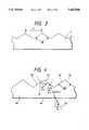
- FIG. 6is a sectional view illustrating the conventional prism plate on an enlarged scale.
- Reference numeral 60denotes a prism plate and 61 denotes a ray of light.
- a dotted line 71represents the angle dependency of light intensity of the ray of light 61 incident on the prism plate 60 which corresponds to the visual angle characteristic as if there is no prism plate 60.
- the luminanceis increased by more than 1.4 times over an effective range of visual angle of from -35 degree to 35 degrees.
- the lightis also emitted over ineffective ranges of visual angle from -80 degrees to -60 degrees and from 60 degrees to 80 degrees resulting in wasteful consumption of electric power.
- the indicatoris unnecessarily bright.
- the causeis attributed, as shown in FIG. 6, to the fact that the ray of light 61 incident on the prism plate 60 is totally reflected by the prism plane 62 and is emitted from the prism plane 63.
- An object of the present inventionis to solve the above-mentioned problems by providing an indicator which prevents light from being emitted into ineffective ranges of visual angle, so as to increase the intensity of light emitted within an effective range of visual angle. It is another object of the present invention to provide an indicator which has a small thickness and consumes a small amount of electric power, thereby being particularly suitable for portable information processors.
- the basic concept of the present inventionis the recognition that the prism plate gathers the light from the scattering plate in the direction of an effective visual angle (for example from -60 degree to +60 degree as shown in FIG. 7), and minimizes intensity of outgoing light in the direction of a noneffective visual angle. And more desirably, the present invention is effective to assure that there is no peak of the intensity of outgoing light in the direction of the noneffective angle.
- Another aspect of the present inventionis a prism plate having prism-like protuberances formed at a side thereof, in which the vertex angle 2 ⁇ formed by two planes of each prism-like protuberance is defined by the formula,
- nis the refractive index of the prism plate medium.
- an data indicator for an information processorcomprises a light source, a scattering plate which scatters light from the light source, an indicator plate irradiated with scattered light from the scattering plate, and a prism plate having many prism-like protuberances formed on one side thereof and being disposed between the scattering plate and the indicator plate such that the prism-like protuberances face the scattering plate, and, the vertical angle 2 ⁇ formed by two planes of each of the prism-like protuberances is,
- nis the refractive index of the prism plate
- n'is the refractive index of the material in which the prism plate is arranged.
- the totally reflected scattered light from one surface of the prism-like protuberanceis also totally reflected on the other surface of the prism-like protuberance, thereby making it possible to gather the emitted light only in the effective range of visual angle.
- FIG. 1is a sectional view of a liquid crystal indicator of the side light type in accordance with one embodiment of the present invention
- FIG. 2is an exploded perspective view of the indicator of FIG. 1 showing the liquid crystal indicator of the present invention
- FIG. 3is an enlarged sectional view which illustrates a prism plate embodying the present invention
- FIG. 4is a diagram showing a ray trace of the prism plate
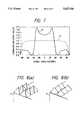
- FIG. 5shows the visual angle characteristic of the prism plate of the present invention
- FIG. 6is an enlarged sectional view which illustrates a conventional prism plate
- FIG. 7shows the visual angle characteristic of the conventional prism plate of FIG. 6.
- FIGS. 8 (a) and (b)are enlarged perspective views showing two protuberance structures at the surface of the prism plate of the type shown in FIGS. 3 and 4 in accordance with the present invention.
- reference numeral 1denotes a cold cathode-ray tube
- 2denotes a reflector plate
- 3denotes a lightguide plate made of an acrylic resin or the like resin and having a reflector 4 such as white paint applied to the lower surface thereof.
- Reference numeral 5denotes a thin scattering plate having fine roughness on the surface thereof which is placed on the upper surface of the lightguide plate 3
- reference numeral 6denotes a prism plate whose lower side is flat and which has prism protuberances formed on the upper side thereof
- reference number 7denotes a liquid crystal indicator element.
- FIG. 4is a ray-trace diagram of light of the prism plate.
- Reference numeral 40denotes a prism plate having a vertex angle between a prism plane 42 and a prism plane 43 of 2 ⁇ (a half vertex angle is ⁇ ) and a refractive index of n
- 41denotes a ray of light having an angle of incidence of ⁇ (the direction indicated by arrow in FIG. 4 is assumed to be negative).
- the angle of refraction ⁇ ' on a plane 44(direction indicated by arrow in FIG. 4 is assumed to be negative) and the angle of incidence ⁇ on the prism plane 42 (direction indicated by arrow in FIG. 4 is assumed to be negative) are given by:
- the angle of incidence ⁇ on the prism plane 43is given as the following formula:
- the incidence ⁇becomes smaller, the incidence ⁇ becomes larger.
- the smallest angle of incidence ⁇is - ⁇ /2. So if sin ⁇ is -1 and if
- the totally reflected scattered light from the surface 42is also totally reflected on the surface 43.
- Such prism platemakes it possible to prevent the light from being emitted in the ineffective range of visual angle that has been a problem inherent in the prior art, and further makes it possible to utilize the light that has hitherto been emitted to ineffective ranges of visual angle, as incident light that falls on the prism plate. This enables the light intensity within an effective range of visual angle to be increased substantially more than that of the prior art.
- the material around the prism plateis, for example, air or vacuum whose refractive index is 1. If the material around the prism plate is another material (for example, liquid such as oil or water, or transparent solid matter such as resin or glass) whose refractive index is n', the inequality (8) should be rewritten to inequality (9) as follows;
- the light emitted from the cold cathode-ray tube 1is incident on the side surface of the lightguide plate 3 directly or after-reflected from the reflector plate 2, reflected by the reflection member 4 applied to the lower side of the lightguide plate 3, and emitted from the upper side of the lightguide plate 3.
- the light emitted from the lightguide plate 3is distributed through the scattering plate 5, and hence the light intensity is of a uniform distribution over a wide range of angles.
- the prism plate 6utilizing the principles of the present invention emits light only within an effective range of visual angle, so that information is indicated through the liquid crystal indicator element 7.
- FIG. 3is an enlarged sectional view of the prism plate 6.
- the prism plate 6is made of an acrylic resin and has a refractive index n of 1.585.
- the vertex 2 ⁇ of the prism formed on the upper sideis set to an angle which is greater than 112.2 degrees. For instance, 120 degrees (half vertex angle ⁇ is 60 degrees) is desirable.
- the pitch P of the prismis, for example, 50 ⁇ m.
- FIGS. 1 to 3the shapes of the prisms are shown in an exaggerated manner with respect to the thickness of the prism plate.
- the prism platehas a thickness of, for example, 1 min.
- a solid line 50 of FIG. 5represents the visual angle characteristic of the outgoing light of the prism plate 6 found by the ray trace calculation, similar to that of FIG. 7. Furthermore, a dotted line 71 corresponds to the visual angle characteristic of the scattering plate 5 as would occur when there is no prism plate 6, similar to that of FIG. 7, and shows a uniform distribution of light intensity over a wide range of angle of about +/-(plus/minus) 80 degrees. As shown by the solid line 50 in FIG. 5, no light is emitted over ineffective ranges of visual angle of smaller than -60 degrees and greater than 60 degrees, and the electric power is thus not wastefully consumed. Even when viewed from these directions, the indicator is not unnecessarily bright. Moreover, the effective range of visual angle is +/-45 degrees which is wider than the effective range of visual angle of +/-35 degrees as shown by the solid line 70 of FIG. 7, and the luminance is increased by more than 1.4 times.
- the prism plateneed only have a refractive index and a vertex angle which satisfy the inequality (8).
- the prism plateis not limited to the one that has a prism shape only in one direction as shown in FIGS. 1 and 2, but can be those of a pyramid shape as shown in FIG. 8(a) or a conical shape having a prism shape in cross section in two directions, which is shown in FIG. 8(b).
- the inventionis not limited to the specific features shown in FIGS. 1 and 2, but can also include an embodiment in which the positions of the prism plate and the liquid crystal indicator element are exchanged.
- the indicatorcan be a liquid crystal indicator of the back-light type as shown in FIGS. 1 and 2 of Japanese Patent Laid-Open No. 67016/1992.
- the present inventionprovides an indicator which prevents light from being emitted into ineffective ranges of visual angle, increases the intensity of light emitted within an effective range of visual angle, has a small thickness and consumes a small amount of electric power, and hence is particularly suitable for use in a portable information processor,
Landscapes
- Physics & Mathematics (AREA)
- General Physics & Mathematics (AREA)
- Optics & Photonics (AREA)
- Nonlinear Science (AREA)
- Engineering & Computer Science (AREA)
- General Engineering & Computer Science (AREA)
- Mathematical Physics (AREA)
- Chemical & Material Sciences (AREA)
- Crystallography & Structural Chemistry (AREA)
- Optical Elements Other Than Lenses (AREA)
- Liquid Crystal (AREA)
- Light Guides In General And Applications Therefor (AREA)
Abstract
Description
2θ>2/3(π/2+2×arcsin(1/n))
2θ>2/3×(π/2+2×arcsin (n'/n))
α'=arcsin(1/n×sinα) . . . (1)
β=α'+θ-π/2 . . . (2)
δ=-β-2θ. . . (3
n×sinδ<-1 . . . (4)
δ<arcsin (-1/n) . . . (5)
β>2θ+arcsin (1/n) . . . (6)
θ>1/3×(π/2+arcsin (1/n)-α') . . . (7)
2θ>2/3(π/2+2×arcsin (1/n)) . . . (8)
2θ>2/3(π/2+2×arcsin(n'/n)) . . . (9)
2/3 (π/2+2×arcsin (1/n))=112.2 degrees
2θ>112.2 degrees
Claims (11)
2θ>2/3×(π/2+2×arcsin (1/n))
θ> 2/3×(π/2+2×arcsin (n'/n))
2θ>2/3×(π/2+2×arcsin (1/n))
Priority Applications (1)
| Application Number | Priority Date | Filing Date | Title |
|---|---|---|---|
| US08/533,547US5627926A (en) | 1992-09-16 | 1995-09-25 | Prism plate for efficiently emitting light flux within a predetermined range, and liquid crystal indicator and indicator illumination method using the same |
Applications Claiming Priority (4)
| Application Number | Priority Date | Filing Date | Title |
|---|---|---|---|
| JP4246178AJPH0695112A (en) | 1992-09-16 | 1992-09-16 | Prism plate and information display device formed by using this plate |
| JP4-246178 | 1992-09-16 | ||
| US08/117,789US5467417A (en) | 1992-09-16 | 1993-09-08 | Prism plate for efficiently emitting light flux within a predetermined range, and liquid crystal indicator and indicator illumination method using the same |
| US08/533,547US5627926A (en) | 1992-09-16 | 1995-09-25 | Prism plate for efficiently emitting light flux within a predetermined range, and liquid crystal indicator and indicator illumination method using the same |
Related Parent Applications (1)
| Application Number | Title | Priority Date | Filing Date |
|---|---|---|---|
| US08/117,789DivisionUS5467417A (en) | 1992-09-16 | 1993-09-08 | Prism plate for efficiently emitting light flux within a predetermined range, and liquid crystal indicator and indicator illumination method using the same |
Publications (1)
| Publication Number | Publication Date |
|---|---|
| US5627926Atrue US5627926A (en) | 1997-05-06 |
Family
ID=17144681
Family Applications (2)
| Application Number | Title | Priority Date | Filing Date |
|---|---|---|---|
| US08/117,789Expired - LifetimeUS5467417A (en) | 1992-09-16 | 1993-09-08 | Prism plate for efficiently emitting light flux within a predetermined range, and liquid crystal indicator and indicator illumination method using the same |
| US08/533,547Expired - LifetimeUS5627926A (en) | 1992-09-16 | 1995-09-25 | Prism plate for efficiently emitting light flux within a predetermined range, and liquid crystal indicator and indicator illumination method using the same |
Family Applications Before (1)
| Application Number | Title | Priority Date | Filing Date |
|---|---|---|---|
| US08/117,789Expired - LifetimeUS5467417A (en) | 1992-09-16 | 1993-09-08 | Prism plate for efficiently emitting light flux within a predetermined range, and liquid crystal indicator and indicator illumination method using the same |
Country Status (3)
| Country | Link |
|---|---|
| US (2) | US5467417A (en) |
| JP (1) | JPH0695112A (en) |
| KR (1) | KR100387172B1 (en) |
Cited By (45)
| Publication number | Priority date | Publication date | Assignee | Title |
|---|---|---|---|---|
| WO1998015862A1 (en)* | 1996-10-08 | 1998-04-16 | Clio Technologies, Inc. | A divergent angle rotator system and method for collimating light |
| US5818555A (en)* | 1993-11-05 | 1998-10-06 | Enplas Corporation | Surface light source device |
| GB2334806A (en)* | 1998-02-26 | 1999-09-01 | Taiwan Liton Electronic Co Ltd | Enhanced back light structure |
| US6025897A (en) | 1993-12-21 | 2000-02-15 | 3M Innovative Properties Co. | Display with reflective polarizer and randomizing cavity |
| US6099135A (en)* | 1996-02-01 | 2000-08-08 | Mitsubishi Rayon Co., Ltd. | Surface light source element and liquid crystal display device, sign device and traffic control sign device using same |
| US6104455A (en)* | 1997-08-27 | 2000-08-15 | Dai Nippon Printing Co., Ltd. | Back light device and liquid crystal display apparatus |
| US6147725A (en)* | 1997-11-21 | 2000-11-14 | Mitsubishi Denki Kabushiki Kaisha | Liquid crystal panel module with polarization transformation for increased brightness |
| EP1055944A1 (en)* | 1999-05-24 | 2000-11-29 | Nitto Denko Corporation | Polarizing element and optical element |
| US6231200B1 (en)* | 1995-10-13 | 2001-05-15 | Omron Corporation | Surface light source device, elements therefor and apparatus using the same |
| US6354709B1 (en) | 1998-02-18 | 2002-03-12 | 3M Innovative Properties Company | Optical film |
| US6356391B1 (en) | 1999-10-08 | 2002-03-12 | 3M Innovative Properties Company | Optical film with variable angle prisms |
| US6447135B1 (en) | 1999-10-08 | 2002-09-10 | 3M Innovative Properties Company | Lightguide having a directly secured reflector and method of making the same |
| US6502947B2 (en)* | 2001-03-30 | 2003-01-07 | Mitsubishi Rayon Co., Ltd. | Planar light source device and liquid crystal display apparatus |
| US20030030764A1 (en)* | 2001-07-13 | 2003-02-13 | Hea-Chun Lee | Light guiding plate, method of manufacturing the same and liquid crystal display having the light guiding plate |
| US20030058553A1 (en)* | 2001-08-03 | 2003-03-27 | Epstein Kenneth A. | Optical film having microreplicated structures; and methods |
| US6578976B2 (en)* | 2000-08-18 | 2003-06-17 | Klaus Bothe | Lighting device |
| US6581286B2 (en) | 2000-04-05 | 2003-06-24 | 3M Innovative Properties Company | Method of making tool to produce optical film |
| US20030117791A1 (en)* | 2001-12-26 | 2003-06-26 | Lg.Philips Lcd Co., Ltd. | Backlight unit |
| US20030174490A1 (en)* | 2000-05-19 | 2003-09-18 | Heather Allinson | Edge lit illumination devices |
| US20030202338A1 (en)* | 1999-02-23 | 2003-10-30 | Parker Jeffery R. | Light emitting panel assemblies |
| US20040141103A1 (en)* | 2003-01-16 | 2004-07-22 | Kotchick Keith M. | Packaging and handling method for optical films |
| US20040196645A1 (en)* | 2000-12-21 | 2004-10-07 | Heather Allinson | Edge lit illumination devices |
| US20050001043A1 (en)* | 1999-10-08 | 2005-01-06 | 3M Innovative Properties Company | Optical elements having programmed optical structures |
| US20050046767A1 (en)* | 2003-08-29 | 2005-03-03 | Freking Anthony J. | Adhesive stacking for multiple optical films |
| US6903788B2 (en) | 2001-07-05 | 2005-06-07 | Nitto Denko Corporation | Optical film and a liquid crystal display using the same |
| US20050134963A1 (en)* | 2003-05-16 | 2005-06-23 | 3M Innovative Properties Company | Method for stacking surface structured optical films |
| US20050146881A1 (en)* | 2003-12-31 | 2005-07-07 | Freking Anthony J. | Cover removal tab for optical products |
| US20050238852A1 (en)* | 2004-04-23 | 2005-10-27 | Naoki Nakayama | Optical products for displays |
| US20060051048A1 (en)* | 1999-10-08 | 2006-03-09 | Gardiner Mark E | Backlight with structured surfaces |
| US20060109687A1 (en)* | 2004-11-22 | 2006-05-25 | Campbell Alan B | Optical film |
| US20060109645A1 (en)* | 2004-11-22 | 2006-05-25 | Ferrari John S | Hand worn illuminated framework |
| US20060158592A1 (en)* | 2005-01-14 | 2006-07-20 | Freking Anthony J | Pre-stacked optical films |
| GB2427676A (en)* | 2005-06-29 | 2007-01-03 | Lg Philips Lcd Co Ltd | Prism Sheet and Backlight Unit Using The Same |
| US20070115407A1 (en)* | 2005-11-18 | 2007-05-24 | 3M Innovative Properties Company | Multi-function enhacement film |
| US20090067784A1 (en)* | 2007-09-10 | 2009-03-12 | Banyan Energy, Inc. | Compact optics for concentration, aggregation and illumination of light energy |
| US20090064993A1 (en)* | 2007-09-10 | 2009-03-12 | Banyan Energy, Inc. | Solar energy concentrator |
| US7852560B2 (en) | 1993-12-21 | 2010-12-14 | 3M Innovative Properties Company | Display incorporating reflective polarizer |
| US20100328283A1 (en)* | 2009-06-29 | 2010-12-30 | Research In Motion Limited | Wave guide for improving light sensor angular response |
| EP2362250A1 (en)* | 2010-02-26 | 2011-08-31 | Research In Motion Limited | Light guide for improving device lighting |
| US20110210921A1 (en)* | 2010-02-26 | 2011-09-01 | Research In Motion Limited | Light guide for improving device lighting |
| US20110241977A1 (en)* | 2010-04-01 | 2011-10-06 | Microsoft Corporation | Enhanced viewing brightness for surface display |
| US20120069597A1 (en)* | 2009-03-26 | 2012-03-22 | Naoya Sone | Planar light source device having light guide plate with reflective member |
| US8412010B2 (en) | 2007-09-10 | 2013-04-02 | Banyan Energy, Inc. | Compact optics for concentration and illumination systems |
| TWI397743B (en)* | 2008-08-22 | 2013-06-01 | Shenzhen China Star Optoelect | Prism sheet and backlight module |
| US8705914B2 (en) | 2007-09-10 | 2014-04-22 | Banyan Energy, Inc. | Redirecting optics for concentration and illumination systems |
Families Citing this family (92)
| Publication number | Priority date | Publication date | Assignee | Title |
|---|---|---|---|---|
| US5816677A (en)* | 1905-03-01 | 1998-10-06 | Canon Kabushiki Kaisha | Backlight device for display apparatus |
| US6002829A (en) | 1992-03-23 | 1999-12-14 | Minnesota Mining And Manufacturing Company | Luminaire device |
| JPH0695112A (en)* | 1992-09-16 | 1994-04-08 | Hitachi Ltd | Prism plate and information display device formed by using this plate |
| USRE37377E1 (en) | 1992-10-09 | 2001-09-18 | Asahi Glass Company, Ltd. | LCD device including an illumination device having a polarized light separating sheet between a light guide and the display |
| TW594115B (en)* | 1992-10-09 | 2004-06-21 | Asahi Glass Co Ltd | A liquid crystal display device and an illumination device for a direct viewing type display element |
| JPH07104290A (en)* | 1993-09-30 | 1995-04-21 | Sharp Corp | Illuminating device and liquid crystal display device formed by using the same |
| US5521725A (en)* | 1993-11-05 | 1996-05-28 | Alliedsignal Inc. | Illumination system employing an array of microprisms |
| US6129439A (en)* | 1993-11-05 | 2000-10-10 | Alliedsignal Inc. | Illumination system employing an array of multi-faceted microprisms |
| JPH07169311A (en)* | 1993-12-17 | 1995-07-04 | Enplas Corp | Light scattering photoconductive light source and liquid crystal display |
| US5659410A (en)* | 1993-12-28 | 1997-08-19 | Enplas Corporation | Surface light source device and liquid crystal display |
| JPH07248494A (en)* | 1994-03-14 | 1995-09-26 | Hitachi Ltd | Liquid crystal display |
| JP2742880B2 (en)* | 1994-08-12 | 1998-04-22 | 大日本印刷株式会社 | Surface light source, display device using the same, and light diffusion sheet used for them |
| JP3920364B2 (en)* | 1994-12-28 | 2007-05-30 | 株式会社エンプラス | Two-beam generation method and two-beam generation type surface light source device |
| KR0163895B1 (en)* | 1995-01-06 | 1999-01-15 | 김광호 | LCD with improved viewing angle |
| JPH11508702A (en) | 1995-06-26 | 1999-07-27 | ミネソタ マイニング アンド マニュファクチャリング カンパニー | Backlight system with multilayer optical film reflector |
| US5613751A (en) | 1995-06-27 | 1997-03-25 | Lumitex, Inc. | Light emitting panel assemblies |
| US7108414B2 (en) | 1995-06-27 | 2006-09-19 | Solid State Opto Limited | Light emitting panel assemblies |
| JP3548812B2 (en)* | 1995-08-11 | 2004-07-28 | オムロン株式会社 | Surface light source device, planar optical element used in the device, and image display device using the device |
| JPH0981049A (en)* | 1995-09-12 | 1997-03-28 | Enplas Corp | Side light type surface light source device |
| US7907319B2 (en) | 1995-11-06 | 2011-03-15 | Qualcomm Mems Technologies, Inc. | Method and device for modulating light with optical compensation |
| US5895115A (en)* | 1996-01-16 | 1999-04-20 | Lumitex, Inc. | Light emitting panel assemblies for use in automotive applications and the like |
| US5917664A (en)* | 1996-02-05 | 1999-06-29 | 3M Innovative Properties Company | Brightness enhancement film with soft cutoff |
| US5838403A (en)* | 1996-02-14 | 1998-11-17 | Physical Optics Corporation | Liquid crystal display system with internally reflecting waveguide for backlighting and non-Lambertian diffusing |
| US6072551A (en)* | 1996-02-14 | 2000-06-06 | Physical Optics Corporation | Backlight apparatus for illuminating a display with controlled light output characteristics |
| DE19610816C2 (en)* | 1996-03-19 | 1999-02-04 | Ctx Opto Electronics Corp | Backlight system for a scoreboard |
| JPH09274184A (en)* | 1996-04-04 | 1997-10-21 | Dainippon Printing Co Ltd | Lens film and surface light source device using the same |
| WO1998036315A1 (en)* | 1997-02-13 | 1998-08-20 | Alliedsignal Inc. | Illumination system with light recycling to enhance brightness |
| DE69836042T2 (en)* | 1997-03-04 | 2007-02-22 | Matsushita Electric Industrial Co., Ltd., Kadoma | Linear lighting device |
| US5903392A (en)* | 1997-05-19 | 1999-05-11 | Dai Nippon Printing Co., Ltd. | Reflecting screen |
| JP3669541B2 (en)* | 1997-06-12 | 2005-07-06 | 株式会社エンプラス | Sidelight type surface light source device |
| WO1999052006A2 (en) | 1998-04-08 | 1999-10-14 | Etalon, Inc. | Interferometric modulation of radiation |
| US8928967B2 (en) | 1998-04-08 | 2015-01-06 | Qualcomm Mems Technologies, Inc. | Method and device for modulating light |
| US6106128A (en)* | 1998-09-11 | 2000-08-22 | Honeywell International Inc. | Illumination system having edge-illuminated waveguide and separate components for extracting and directing light |
| US6199989B1 (en) | 1998-10-29 | 2001-03-13 | Sumitomo Chemical Company, Limited | Optical plate having reflecting function and transmitting function |
| KR100450542B1 (en)* | 1998-10-29 | 2004-10-01 | 가부시키가이샤 히타치세이사쿠쇼 | Illuminating apparatus and liquid crystal display using the same |
| US7364341B2 (en)* | 1999-02-23 | 2008-04-29 | Solid State Opto Limited | Light redirecting films including non-interlockable optical elements |
| US6827456B2 (en) | 1999-02-23 | 2004-12-07 | Solid State Opto Limited | Transreflectors, transreflector systems and displays and methods of making transreflectors |
| US6752505B2 (en) | 1999-02-23 | 2004-06-22 | Solid State Opto Limited | Light redirecting films and film systems |
| EP1085252B1 (en)* | 1999-09-17 | 2015-06-10 | Siteco Beleuchtungstechnik GmbH | Light guide luminaire comprising improved shielding means |
| JP3862926B2 (en)* | 2000-03-31 | 2006-12-27 | 株式会社エンプラス | Surface light source device and liquid crystal display |
| TW575185U (en)* | 2002-11-15 | 2004-02-01 | Hon Hai Prec Ind Co Ltd | Backlight system and light guide plate thereof |
| TWI289708B (en) | 2002-12-25 | 2007-11-11 | Qualcomm Mems Technologies Inc | Optical interference type color display |
| TWI302622B (en)* | 2003-02-21 | 2008-11-01 | Au Optronics Corp | A liquid crystal display |
| US7342705B2 (en) | 2004-02-03 | 2008-03-11 | Idc, Llc | Spatial light modulator with integrated optical compensation structure |
| US7706050B2 (en) | 2004-03-05 | 2010-04-27 | Qualcomm Mems Technologies, Inc. | Integrated modulator illumination |
| JP2005274933A (en)* | 2004-03-24 | 2005-10-06 | Seiko Epson Corp | Light source device and projector |
| US7293876B2 (en)* | 2004-03-24 | 2007-11-13 | Seiko Epson Corporation | Light source unit and projector |
| US7630123B2 (en) | 2004-09-27 | 2009-12-08 | Qualcomm Mems Technologies, Inc. | Method and device for compensating for color shift as a function of angle of view |
| US7813026B2 (en) | 2004-09-27 | 2010-10-12 | Qualcomm Mems Technologies, Inc. | System and method of reducing color shift in a display |
| US7750886B2 (en) | 2004-09-27 | 2010-07-06 | Qualcomm Mems Technologies, Inc. | Methods and devices for lighting displays |
| US7508571B2 (en) | 2004-09-27 | 2009-03-24 | Idc, Llc | Optical films for controlling angular characteristics of displays |
| US20060083022A1 (en)* | 2004-10-18 | 2006-04-20 | Forhouse Corporation | Backlight unit for liquid crystal display |
| WO2006052755A2 (en) | 2004-11-04 | 2006-05-18 | Solid State Opto Limited | Long curved wedges in an optical film |
| JP4311366B2 (en)* | 2005-03-28 | 2009-08-12 | 日本電気株式会社 | Light source device, display device, terminal device, and optical member |
| KR20060112570A (en)* | 2005-04-27 | 2006-11-01 | 삼성전자주식회사 | Back light assembly and liquid crystal display device having same |
| CN100419522C (en)* | 2005-08-19 | 2008-09-17 | 鸿富锦精密工业(深圳)有限公司 | Light guide plate and backlight system |
| RU2297021C1 (en)* | 2005-10-06 | 2007-04-10 | Самсунг Электроникс Ко., Лтд. | Optical film |
| DE102005051965A1 (en)* | 2005-10-29 | 2007-05-03 | GM Global Technology Operations, Inc., Detroit | Motor vehicle consists of windshield, display device with display whereby side of the fiber optic light guide turned towards back side of display has a micro-structure |
| US7916980B2 (en) | 2006-01-13 | 2011-03-29 | Qualcomm Mems Technologies, Inc. | Interconnect structure for MEMS device |
| CN101000387A (en)* | 2006-01-14 | 2007-07-18 | 鸿富锦精密工业(深圳)有限公司 | Prism and backlight module using the prism |
| US7603001B2 (en) | 2006-02-17 | 2009-10-13 | Qualcomm Mems Technologies, Inc. | Method and apparatus for providing back-lighting in an interferometric modulator display device |
| US7766498B2 (en) | 2006-06-21 | 2010-08-03 | Qualcomm Mems Technologies, Inc. | Linear solid state illuminator |
| US7845841B2 (en)* | 2006-08-28 | 2010-12-07 | Qualcomm Mems Technologies, Inc. | Angle sweeping holographic illuminator |
| EP1943551A2 (en) | 2006-10-06 | 2008-07-16 | Qualcomm Mems Technologies, Inc. | Light guide |
| US7855827B2 (en) | 2006-10-06 | 2010-12-21 | Qualcomm Mems Technologies, Inc. | Internal optical isolation structure for integrated front or back lighting |
| US8107155B2 (en) | 2006-10-06 | 2012-01-31 | Qualcomm Mems Technologies, Inc. | System and method for reducing visual artifacts in displays |
| EP1943555B1 (en) | 2006-10-06 | 2012-05-02 | QUALCOMM MEMS Technologies, Inc. | Optical loss structure integrated in an illumination apparatus of a display |
| EP2069838A2 (en) | 2006-10-06 | 2009-06-17 | Qualcomm Mems Technologies, Inc. | Illumination device with built-in light coupler |
| EP1958010A2 (en) | 2006-10-10 | 2008-08-20 | Qualcomm Mems Technologies, Inc | Display device with diffractive optics |
| US7864395B2 (en) | 2006-10-27 | 2011-01-04 | Qualcomm Mems Technologies, Inc. | Light guide including optical scattering elements and a method of manufacture |
| US7777954B2 (en) | 2007-01-30 | 2010-08-17 | Qualcomm Mems Technologies, Inc. | Systems and methods of providing a light guiding layer |
| US7733439B2 (en) | 2007-04-30 | 2010-06-08 | Qualcomm Mems Technologies, Inc. | Dual film light guide for illuminating displays |
| US8068710B2 (en) | 2007-12-07 | 2011-11-29 | Qualcomm Mems Technologies, Inc. | Decoupled holographic film and diffuser |
| US8721149B2 (en) | 2008-01-30 | 2014-05-13 | Qualcomm Mems Technologies, Inc. | Illumination device having a tapered light guide |
| JP2011512006A (en) | 2008-01-30 | 2011-04-14 | デジタル オプティクス インターナショナル,リミティド ライアビリティ カンパニー | Thin lighting system |
| WO2009102731A2 (en) | 2008-02-12 | 2009-08-20 | Qualcomm Mems Technologies, Inc. | Devices and methods for enhancing brightness of displays using angle conversion layers |
| WO2009129264A1 (en) | 2008-04-15 | 2009-10-22 | Qualcomm Mems Technologies, Inc. | Light with bi-directional propagation |
| US7639918B2 (en)* | 2008-05-05 | 2009-12-29 | Visteon Global Technologies, Inc. | Manifold-type lightguide with reduced thickness |
| US8462292B2 (en) | 2008-07-31 | 2013-06-11 | Rambus Delaware Llc | Optically transmissive substrates and light emitting assemblies and methods of making same, and methods of displaying images using the optically transmissive substrates and light emitting assemblies |
| JP5492899B2 (en) | 2008-10-10 | 2014-05-14 | クォルコム・メムズ・テクノロジーズ・インコーポレーテッド | Distributed lighting system |
| EP2184628A3 (en)* | 2008-11-06 | 2010-10-06 | CEAG Notlichtsysteme GmbH | Lights, in particular emergency, rescue or safety lights |
| TWI410712B (en)* | 2009-01-13 | 2013-10-01 | Ind Tech Res Inst | Optical film |
| KR20110104090A (en) | 2009-01-13 | 2011-09-21 | 퀄컴 엠이엠스 테크놀로지스, 인크. | Large Area Light Panels and Screens |
| CN101852878B (en)* | 2009-04-02 | 2014-03-12 | 财团法人工业技术研究院 | Optical film |
| CN102449512A (en) | 2009-05-29 | 2012-05-09 | 高通Mems科技公司 | Illumination devices and methods of fabrication thereof |
| US20120051088A1 (en)* | 2010-08-25 | 2012-03-01 | Qualcomm Mems Technologies, Inc. | Methods of manufacturing illumination systems |
| US8402647B2 (en) | 2010-08-25 | 2013-03-26 | Qualcomm Mems Technologies Inc. | Methods of manufacturing illumination systems |
| US8902484B2 (en) | 2010-12-15 | 2014-12-02 | Qualcomm Mems Technologies, Inc. | Holographic brightness enhancement film |
| US9645301B2 (en)* | 2014-03-28 | 2017-05-09 | Rambus Delaware Llc | Lighting assembly with edge-lit light guide and structured cover |
| KR102525646B1 (en) | 2016-04-19 | 2023-04-26 | 삼성디스플레이 주식회사 | Display apparatus |
| CN107300808B (en)* | 2017-07-12 | 2020-04-28 | 厦门天马微电子有限公司 | Backlight module and display device thereof |
| CN107450233A (en)* | 2017-09-15 | 2017-12-08 | 广东朝野科技有限公司 | A kind of straight-down negative LED liquid crystal television backing structure of low-power consumption |
Citations (9)
| Publication number | Priority date | Publication date | Assignee | Title |
|---|---|---|---|---|
| US5050946A (en)* | 1990-09-27 | 1991-09-24 | Compaq Computer Corporation | Faceted light pipe |
| US5211463A (en)* | 1992-03-11 | 1993-05-18 | Kaiser Aerospace & Electronics Corporation | Backlight for liquid crystal devices |
| US5237641A (en)* | 1992-03-23 | 1993-08-17 | Nioptics Corporation | Tapered multilayer luminaire devices |
| US5303322A (en)* | 1992-03-23 | 1994-04-12 | Nioptics Corporation | Tapered multilayer luminaire devices |
| US5339382A (en)* | 1993-02-23 | 1994-08-16 | Minnesota Mining And Manufacturing Company | Prism light guide luminaire with efficient directional output |
| US5353133A (en)* | 1991-11-25 | 1994-10-04 | Magnascreen Corporation | A display having a standard or reversed schieren microprojector at each picture element |
| US5359691A (en)* | 1992-10-08 | 1994-10-25 | Briteview Technologies | Backlighting system with a multi-reflection light injection system and using microprisms |
| US5467417A (en)* | 1992-09-16 | 1995-11-14 | Hitachi, Ltd. | Prism plate for efficiently emitting light flux within a predetermined range, and liquid crystal indicator and indicator illumination method using the same |
| US5479275A (en)* | 1993-12-03 | 1995-12-26 | Ois Optical Imaging Systems, Inc. | Backlit liquid crystal display with integral collimating, refracting, and reflecting means which refracts and collimates light from a first light source and reflects light from a second light source |
Family Cites Families (5)
| Publication number | Priority date | Publication date | Assignee | Title |
|---|---|---|---|---|
| JPH0467016A (en)* | 1990-07-05 | 1992-03-03 | Sharp Corp | liquid crystal display device |
| JP2917584B2 (en)* | 1991-06-05 | 1999-07-12 | ブラザー工業株式会社 | Image recording device |
| US5271077A (en)* | 1992-09-09 | 1993-12-14 | Gte Products Corporation | Nonimaging reflector for coupling light into a light pipe |
| US5337381A (en)* | 1993-01-21 | 1994-08-09 | Fiberguide Industries | Fiber optic cylindrical diffuser |
| US5363458A (en)* | 1994-02-28 | 1994-11-08 | Fiber Guide Industries | Fiber optic light diffuser |
- 1992
- 1992-09-16JPJP4246178Apatent/JPH0695112A/enactivePending
- 1993
- 1993-09-01KRKR1019930017353Apatent/KR100387172B1/ennot_activeExpired - Lifetime
- 1993-09-08USUS08/117,789patent/US5467417A/ennot_activeExpired - Lifetime
- 1995
- 1995-09-25USUS08/533,547patent/US5627926A/ennot_activeExpired - Lifetime
Patent Citations (9)
| Publication number | Priority date | Publication date | Assignee | Title |
|---|---|---|---|---|
| US5050946A (en)* | 1990-09-27 | 1991-09-24 | Compaq Computer Corporation | Faceted light pipe |
| US5353133A (en)* | 1991-11-25 | 1994-10-04 | Magnascreen Corporation | A display having a standard or reversed schieren microprojector at each picture element |
| US5211463A (en)* | 1992-03-11 | 1993-05-18 | Kaiser Aerospace & Electronics Corporation | Backlight for liquid crystal devices |
| US5237641A (en)* | 1992-03-23 | 1993-08-17 | Nioptics Corporation | Tapered multilayer luminaire devices |
| US5303322A (en)* | 1992-03-23 | 1994-04-12 | Nioptics Corporation | Tapered multilayer luminaire devices |
| US5467417A (en)* | 1992-09-16 | 1995-11-14 | Hitachi, Ltd. | Prism plate for efficiently emitting light flux within a predetermined range, and liquid crystal indicator and indicator illumination method using the same |
| US5359691A (en)* | 1992-10-08 | 1994-10-25 | Briteview Technologies | Backlighting system with a multi-reflection light injection system and using microprisms |
| US5339382A (en)* | 1993-02-23 | 1994-08-16 | Minnesota Mining And Manufacturing Company | Prism light guide luminaire with efficient directional output |
| US5479275A (en)* | 1993-12-03 | 1995-12-26 | Ois Optical Imaging Systems, Inc. | Backlit liquid crystal display with integral collimating, refracting, and reflecting means which refracts and collimates light from a first light source and reflects light from a second light source |
Cited By (87)
| Publication number | Priority date | Publication date | Assignee | Title |
|---|---|---|---|---|
| US5818555A (en)* | 1993-11-05 | 1998-10-06 | Enplas Corporation | Surface light source device |
| US20050270439A1 (en)* | 1993-12-21 | 2005-12-08 | 3M Innovative Properties Company | Display having a reflective polarizer |
| US6025897A (en) | 1993-12-21 | 2000-02-15 | 3M Innovative Properties Co. | Display with reflective polarizer and randomizing cavity |
| US7423708B2 (en) | 1993-12-21 | 2008-09-09 | 3M Innovative Properties Company | Display having a reflective polarizer |
| US7852560B2 (en) | 1993-12-21 | 2010-12-14 | 3M Innovative Properties Company | Display incorporating reflective polarizer |
| US6231200B1 (en)* | 1995-10-13 | 2001-05-15 | Omron Corporation | Surface light source device, elements therefor and apparatus using the same |
| US6244719B1 (en) | 1996-01-02 | 2001-06-12 | Mitsubishi Rayon Co., Ltd. | Surface light source device and liquid crystal display device sign display apparatus and traffic sign display apparatus using the surface light source device |
| US6332691B2 (en) | 1996-02-01 | 2001-12-25 | Mitsubishi Rayon Co., Ltd. | Surface light source device, and liquid crystal display device, sign display apparatus and traffic sign display apparatus using the surface light source device |
| US6099135A (en)* | 1996-02-01 | 2000-08-08 | Mitsubishi Rayon Co., Ltd. | Surface light source element and liquid crystal display device, sign device and traffic control sign device using same |
| US5854872A (en)* | 1996-10-08 | 1998-12-29 | Clio Technologies, Inc. | Divergent angle rotator system and method for collimating light beams |
| WO1998015862A1 (en)* | 1996-10-08 | 1998-04-16 | Clio Technologies, Inc. | A divergent angle rotator system and method for collimating light |
| US6819372B2 (en) | 1997-08-27 | 2004-11-16 | Dai Nippon Printing Co., Ltd. | Back light device with diffusing sheet for a liquid crystal display apparatus |
| US6104455A (en)* | 1997-08-27 | 2000-08-15 | Dai Nippon Printing Co., Ltd. | Back light device and liquid crystal display apparatus |
| US6147725A (en)* | 1997-11-21 | 2000-11-14 | Mitsubishi Denki Kabushiki Kaisha | Liquid crystal panel module with polarization transformation for increased brightness |
| US6354709B1 (en) | 1998-02-18 | 2002-03-12 | 3M Innovative Properties Company | Optical film |
| GB2334806A (en)* | 1998-02-26 | 1999-09-01 | Taiwan Liton Electronic Co Ltd | Enhanced back light structure |
| US7077544B2 (en)* | 1999-02-23 | 2006-07-18 | Solid State Opto Limited | Light emitting panel assemblies |
| US20030202338A1 (en)* | 1999-02-23 | 2003-10-30 | Parker Jeffery R. | Light emitting panel assemblies |
| EP1055944A1 (en)* | 1999-05-24 | 2000-11-29 | Nitto Denko Corporation | Polarizing element and optical element |
| US6707611B2 (en) | 1999-10-08 | 2004-03-16 | 3M Innovative Properties Company | Optical film with variable angle prisms |
| US20050001043A1 (en)* | 1999-10-08 | 2005-01-06 | 3M Innovative Properties Company | Optical elements having programmed optical structures |
| US6356391B1 (en) | 1999-10-08 | 2002-03-12 | 3M Innovative Properties Company | Optical film with variable angle prisms |
| US7046905B1 (en) | 1999-10-08 | 2006-05-16 | 3M Innovative Properties Company | Blacklight with structured surfaces |
| US6560026B2 (en) | 1999-10-08 | 2003-05-06 | Mark E. Gardiner | Optical film with variable angle prisms |
| US7873256B2 (en) | 1999-10-08 | 2011-01-18 | 3M Innovative Properties Company | Backlight with structured surfaces |
| US8588574B2 (en) | 1999-10-08 | 2013-11-19 | 3M Innovative Properties Company | Backlight with structured surfaces |
| US6447135B1 (en) | 1999-10-08 | 2002-09-10 | 3M Innovative Properties Company | Lightguide having a directly secured reflector and method of making the same |
| US20060051048A1 (en)* | 1999-10-08 | 2006-03-09 | Gardiner Mark E | Backlight with structured surfaces |
| US7221847B2 (en) | 1999-10-08 | 2007-05-22 | 3M Innovative Properties Company | Optical elements having programmed optical structures |
| US6845212B2 (en) | 1999-10-08 | 2005-01-18 | 3M Innovative Properties Company | Optical element having programmed optical structures |
| US20080050088A1 (en)* | 1999-10-08 | 2008-02-28 | 3M Innovative Properties Company | Backlight with structured surfaces |
| US6581286B2 (en) | 2000-04-05 | 2003-06-24 | 3M Innovative Properties Company | Method of making tool to produce optical film |
| US20030174490A1 (en)* | 2000-05-19 | 2003-09-18 | Heather Allinson | Edge lit illumination devices |
| US6578976B2 (en)* | 2000-08-18 | 2003-06-17 | Klaus Bothe | Lighting device |
| US20040196645A1 (en)* | 2000-12-21 | 2004-10-07 | Heather Allinson | Edge lit illumination devices |
| US6502947B2 (en)* | 2001-03-30 | 2003-01-07 | Mitsubishi Rayon Co., Ltd. | Planar light source device and liquid crystal display apparatus |
| US6903788B2 (en) | 2001-07-05 | 2005-06-07 | Nitto Denko Corporation | Optical film and a liquid crystal display using the same |
| US7056005B2 (en)* | 2001-07-13 | 2006-06-06 | Samsung Electronics Co., Ltd. | Light guiding plate having brightness enhancement recesses |
| US20060221630A1 (en)* | 2001-07-13 | 2006-10-05 | Hea-Chun Lee | Method for manufacturing a light guiding plate and liquid crystal display |
| US7431493B2 (en) | 2001-07-13 | 2008-10-07 | Samsung Electronics Co., Ltd. | Light guiding plate with brightness enhancement means and liquid crystal display |
| US20030030764A1 (en)* | 2001-07-13 | 2003-02-13 | Hea-Chun Lee | Light guiding plate, method of manufacturing the same and liquid crystal display having the light guiding plate |
| US20030058553A1 (en)* | 2001-08-03 | 2003-03-27 | Epstein Kenneth A. | Optical film having microreplicated structures; and methods |
| US20030117791A1 (en)* | 2001-12-26 | 2003-06-26 | Lg.Philips Lcd Co., Ltd. | Backlight unit |
| US6955460B2 (en)* | 2001-12-26 | 2005-10-18 | Lg.Philips Lcd Co., Ltd. | LCD backlight unit having 40° half power angle without a polarizing sheet |
| US7236217B2 (en) | 2003-01-16 | 2007-06-26 | 3M Innovative Properties Company | Package of optical films with zero-gap bond outside viewing area |
| US20070222914A1 (en)* | 2003-01-16 | 2007-09-27 | 3M Innovative Properties Company | Packaging and handling method for optical films |
| US20040141103A1 (en)* | 2003-01-16 | 2004-07-22 | Kotchick Keith M. | Packaging and handling method for optical films |
| US20050134963A1 (en)* | 2003-05-16 | 2005-06-23 | 3M Innovative Properties Company | Method for stacking surface structured optical films |
| US7413336B2 (en) | 2003-08-29 | 2008-08-19 | 3M Innovative Properties Company | Adhesive stacking for multiple optical films |
| US20080266501A1 (en)* | 2003-08-29 | 2008-10-30 | 3M Innovative Properties Company | Adhesive stacking for multiple optical films |
| US7520654B2 (en) | 2003-08-29 | 2009-04-21 | 3M Innovative Properties Company | Adhesive stacking for multiple optical films |
| US20050046767A1 (en)* | 2003-08-29 | 2005-03-03 | Freking Anthony J. | Adhesive stacking for multiple optical films |
| US7147358B2 (en) | 2003-12-31 | 2006-12-12 | 3M Innovative Properties Company | Cover removal tab for optical products |
| US20050146881A1 (en)* | 2003-12-31 | 2005-07-07 | Freking Anthony J. | Cover removal tab for optical products |
| US20050238852A1 (en)* | 2004-04-23 | 2005-10-27 | Naoki Nakayama | Optical products for displays |
| US7278771B2 (en) | 2004-11-22 | 2007-10-09 | 3M Innovative Properties Company | Optical film |
| US20060109645A1 (en)* | 2004-11-22 | 2006-05-25 | Ferrari John S | Hand worn illuminated framework |
| US20060109687A1 (en)* | 2004-11-22 | 2006-05-25 | Campbell Alan B | Optical film |
| US20080090025A1 (en)* | 2005-01-14 | 2008-04-17 | 3M Innovative Properties Company | Pre-stacked optical films |
| US7339635B2 (en) | 2005-01-14 | 2008-03-04 | 3M Innovative Properties Company | Pre-stacked optical films with adhesive layer |
| US20060158592A1 (en)* | 2005-01-14 | 2006-07-20 | Freking Anthony J | Pre-stacked optical films |
| CN100427976C (en)* | 2005-06-29 | 2008-10-22 | 乐金显示有限公司 | Prism sheet and backlight unit using same |
| DE102005061307B4 (en)* | 2005-06-29 | 2008-05-15 | Lg. Philips Lcd Co., Ltd. | Prism layer and backlight unit using the same |
| GB2427676A (en)* | 2005-06-29 | 2007-01-03 | Lg Philips Lcd Co Ltd | Prism Sheet and Backlight Unit Using The Same |
| US7407317B2 (en) | 2005-06-29 | 2008-08-05 | Lg Display Co., Ltd. | Prism sheet and backlight unit using the same |
| GB2427676B (en)* | 2005-06-29 | 2007-09-05 | Lg Philips Lcd Co Ltd | Prism sheet and backlight unit using the same |
| US20070002576A1 (en)* | 2005-06-29 | 2007-01-04 | Lee Man H | Prism sheet and backlight unit using the same |
| US7777832B2 (en) | 2005-11-18 | 2010-08-17 | 3M Innovative Properties Company | Multi-function enhancement film |
| US20070115407A1 (en)* | 2005-11-18 | 2007-05-24 | 3M Innovative Properties Company | Multi-function enhacement film |
| US7925129B2 (en) | 2007-09-10 | 2011-04-12 | Banyan Energy, Inc. | Compact optics for concentration, aggregation and illumination of light energy |
| US8412010B2 (en) | 2007-09-10 | 2013-04-02 | Banyan Energy, Inc. | Compact optics for concentration and illumination systems |
| US7672549B2 (en) | 2007-09-10 | 2010-03-02 | Banyan Energy, Inc. | Solar energy concentrator |
| US9229144B2 (en) | 2007-09-10 | 2016-01-05 | Banyan Energy Inc. | Redirecting optics for concentration and illumination systems |
| US7664350B2 (en) | 2007-09-10 | 2010-02-16 | Banyan Energy, Inc. | Compact optics for concentration, aggregation and illumination of light energy |
| US20090064993A1 (en)* | 2007-09-10 | 2009-03-12 | Banyan Energy, Inc. | Solar energy concentrator |
| US8705914B2 (en) | 2007-09-10 | 2014-04-22 | Banyan Energy, Inc. | Redirecting optics for concentration and illumination systems |
| US20090067784A1 (en)* | 2007-09-10 | 2009-03-12 | Banyan Energy, Inc. | Compact optics for concentration, aggregation and illumination of light energy |
| US20100142891A1 (en)* | 2007-09-10 | 2010-06-10 | Banyan Energy, Inc. | Compact optics for concentration, aggregation and illumination of light energy |
| TWI397743B (en)* | 2008-08-22 | 2013-06-01 | Shenzhen China Star Optoelect | Prism sheet and backlight module |
| US20120069597A1 (en)* | 2009-03-26 | 2012-03-22 | Naoya Sone | Planar light source device having light guide plate with reflective member |
| US8319764B2 (en) | 2009-06-29 | 2012-11-27 | Research In Motion Limited | Wave guide for improving light sensor angular response |
| US20100328283A1 (en)* | 2009-06-29 | 2010-12-30 | Research In Motion Limited | Wave guide for improving light sensor angular response |
| US8403539B2 (en) | 2010-02-26 | 2013-03-26 | Research In Motion Limited | Light guide for improving device lighting |
| US20110210921A1 (en)* | 2010-02-26 | 2011-09-01 | Research In Motion Limited | Light guide for improving device lighting |
| EP2362250A1 (en)* | 2010-02-26 | 2011-08-31 | Research In Motion Limited | Light guide for improving device lighting |
| CN102822730A (en)* | 2010-04-01 | 2012-12-12 | 微软公司 | Enhanced viewing brightness for surface display |
| US20110241977A1 (en)* | 2010-04-01 | 2011-10-06 | Microsoft Corporation | Enhanced viewing brightness for surface display |
Also Published As
| Publication number | Publication date |
|---|---|
| US5467417A (en) | 1995-11-14 |
| KR940007576A (en) | 1994-04-27 |
| JPH0695112A (en) | 1994-04-08 |
| KR100387172B1 (en) | 2003-08-06 |
Similar Documents
| Publication | Publication Date | Title |
|---|---|---|
| US5627926A (en) | Prism plate for efficiently emitting light flux within a predetermined range, and liquid crystal indicator and indicator illumination method using the same | |
| US6659615B2 (en) | Light pipe and method for producing the same | |
| EP1265096B1 (en) | Spread illuminating apparatus | |
| EP0588504B1 (en) | A backlight device for a liquid crystal display device | |
| US6174064B1 (en) | Light guide panel and plane illuminator apparatus | |
| US7085460B2 (en) | Light guide plate with diffusion dots having scattering particles and surface light source unit incorporating the light guide plate | |
| US7221847B2 (en) | Optical elements having programmed optical structures | |
| JP3642381B2 (en) | Light guide plate, surface light source device, and reflective liquid crystal display device | |
| JP3213496B2 (en) | Lighting equipment | |
| US6590625B1 (en) | Liquid-crystal display device | |
| US20040125590A1 (en) | Light guide plate and surface light source | |
| JP2001035230A (en) | Flat lighting system | |
| US6827457B2 (en) | Light pipe, planar light source unit and reflective liquid-crystal display device | |
| CN2588388Y (en) | Light conducting board device | |
| JPH10206643A (en) | Sheet-like light source device | |
| JP2800628B2 (en) | Lighting equipment | |
| JPH04146401A (en) | Light diffusing device | |
| JPH0581909B2 (en) | ||
| JP3411858B2 (en) | Light guide plate and flat lighting device | |
| JPH11353915A (en) | Surface light source device | |
| JPH03214191A (en) | Plane light emitting device | |
| JP3563521B2 (en) | Marking device | |
| JP3277178B2 (en) | Liquid crystal display | |
| CN112764151B (en) | Surface light source device and liquid crystal display device | |
| JPH04329521A (en) | LCD lighting equipment |
Legal Events
| Date | Code | Title | Description |
|---|---|---|---|
| STCF | Information on status: patent grant | Free format text:PATENTED CASE | |
| FPAY | Fee payment | Year of fee payment:4 | |
| FEPP | Fee payment procedure | Free format text:PAYOR NUMBER ASSIGNED (ORIGINAL EVENT CODE: ASPN); ENTITY STATUS OF PATENT OWNER: LARGE ENTITY Free format text:PAYER NUMBER DE-ASSIGNED (ORIGINAL EVENT CODE: RMPN); ENTITY STATUS OF PATENT OWNER: LARGE ENTITY | |
| FPAY | Fee payment | Year of fee payment:8 | |
| FPAY | Fee payment | Year of fee payment:12 | |
| AS | Assignment | Owner name:PANASONIC LIQUID CRYSTAL DISPLAY CO., LTD., JAPAN Free format text:MERGER/CHANGE OF NAME;ASSIGNOR:IPS ALPHA SUPPORT CO., LTD.;REEL/FRAME:027363/0315 Effective date:20101001 Owner name:IPS ALPHA SUPPORT CO., LTD., JAPAN Free format text:COMPANY SPLIT PLAN TRANSFERRING FIFTY (50) PERCENT SHARE OF PATENTS AND PATENT APPLICATIONS;ASSIGNOR:HITACHI DISPLAYS, LTD.;REEL/FRAME:027362/0466 Effective date:20100630 Owner name:HITACHI DISPLAYS, LTD., JAPAN Free format text:COMPANY SPLIT PLAN TRANSFERRING ONE HUNDRED (100) PERCENT SHARE OF PATENT AND PATENT APPLICATIONS;ASSIGNOR:HITACHI, LTD.;REEL/FRAME:027362/0612 Effective date:20021001 |