US5627727A - Portable computer assembly and method - Google Patents
Portable computer assembly and methodDownload PDFInfo
- Publication number
- US5627727A US5627727AUS08/300,602US30060294AUS5627727AUS 5627727 AUS5627727 AUS 5627727AUS 30060294 AUS30060294 AUS 30060294AUS 5627727 AUS5627727 AUS 5627727A
- Authority
- US
- United States
- Prior art keywords
- receptacle
- portable computer
- base
- release
- assembly
- Prior art date
- Legal status (The legal status is an assumption and is not a legal conclusion. Google has not performed a legal analysis and makes no representation as to the accuracy of the status listed.)
- Expired - Lifetime
Links
Images


Classifications
- G—PHYSICS
- G06—COMPUTING OR CALCULATING; COUNTING
- G06F—ELECTRIC DIGITAL DATA PROCESSING
- G06F1/00—Details not covered by groups G06F3/00 - G06F13/00 and G06F21/00
- G06F1/16—Constructional details or arrangements
- G06F1/1613—Constructional details or arrangements for portable computers
- G06F1/1632—External expansion units, e.g. docking stations
- G—PHYSICS
- G06—COMPUTING OR CALCULATING; COUNTING
- G06F—ELECTRIC DIGITAL DATA PROCESSING
- G06F1/00—Details not covered by groups G06F3/00 - G06F13/00 and G06F21/00
- G06F1/16—Constructional details or arrangements
- G06F1/1613—Constructional details or arrangements for portable computers
- G06F1/1626—Constructional details or arrangements for portable computers with a single-body enclosure integrating a flat display, e.g. Personal Digital Assistants [PDAs]
- Y—GENERAL TAGGING OF NEW TECHNOLOGICAL DEVELOPMENTS; GENERAL TAGGING OF CROSS-SECTIONAL TECHNOLOGIES SPANNING OVER SEVERAL SECTIONS OF THE IPC; TECHNICAL SUBJECTS COVERED BY FORMER USPC CROSS-REFERENCE ART COLLECTIONS [XRACs] AND DIGESTS
- Y10—TECHNICAL SUBJECTS COVERED BY FORMER USPC
- Y10S—TECHNICAL SUBJECTS COVERED BY FORMER USPC CROSS-REFERENCE ART COLLECTIONS [XRACs] AND DIGESTS
- Y10S439/00—Electrical connectors
- Y10S439/929—Connecting base plate or shelf type holder
Definitions
- the present inventionrelates generally to a portable computer assembly, and more particularly to a portable computer assembly which is adapted to facilitate removal of undesirable particulate, such as dust and dirt, therefrom.
- the inventionalso relates to a method of removing undesirable particulate, such as dust and dirt, from a portable computer assembly.
- Portable computer assemblieswhich include a hand held computer and a station in which the hand held computer is able to be stored are known for use in maintenance of product inventory and management of sale of goods.
- U.S. Pat. No. 4,773,032 issued to Uehara et al.discloses a terminal input apparatus for such a use.
- the terminal input apparatusincludes a portable input device having a data input key and a main device provided with a holder for holding the portable input device therein.
- the holderhas a main device side connector which is to be connected to a connector arranged in the lower portion of the portable input device.
- the holderis arranged so that the holder can be moved relative to the main device between a storing position and an extraction position.
- Another problem associated with prior art portable computer assembliesis an inability to quickly and inexpensively repair a damaged receptacle of a station of the portable computer assembly.
- a portable computer assemblywhich includes a portable computer and a receptacle adapted to hold the portable computer.
- the portable computer assemblyfurther includes a base for supporting the receptacle, in addition, the portable computer assembly includes a latch for latching the receptacle to the base.
- a method of removing particulate from a portable computer storage systemwhich has a receptacle, a base and a latch.
- the methodincludes the steps of (1) latching the receptacle to the base so as to prevent release of the receptacle from the base, (2) unlatching the receptacle from the base so as to allow release of the receptacle from the base, (3) separating the receptacle from the base after the unlatching step, and (4) removing particulate from the receptacle after the separating step.
- a portable computer storage systemwhich includes a receptacle adapted to hold a portable computer.
- the systemfurther includes a base for supporting the receptacle.
- the systemincludes a lock and release mechanism for locking the receptacle to the base.
- FIG. 1is a perspective view of a portable computer assembly that incorporates the features of the present invention therein, with the portable computer assembly including a portable computer, a receptacle and a base;
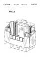
- FIG. 2is a perspective view of the receptacle and base of the portable computer assembly of FIG. 1;
- FIG. 3is a perspective view of the receptacle of the portable computer assembly of FIG. 1;
- FIG. 4is an elevational view of the bottom portion of the receptacle of the portable computer assembly of FIG. 1;
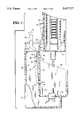
- FIG. 5is a sectional view of the portable computer assembly of FIG. 1, with the portable computer shown removed for clarity of description and with the receptacle shown in its first latched position;
- FIG. 6is a view similar to FIG. 5 but showing the receptacle in its second latched position
- FIG. 7is a view similar to FIG. 6 but showing the receptacle in its unlatched or released position
- FIG. 8is a rear elevational view of the receptacle of the portable computer assembly of FIG. 1;
- FIG. 9is schematic view of a locking mechanism of the portable computer assembly of FIG. 1, with the locking mechanism locking the portable computer to the receptacle when the receptacle is in the first latched position;
- FIG. 10is a perspective view of the portable computer of the portable computer assembly of FIG. 1;
- FIG. 11is a fragmentary perspective view of a rear side of the portable computer of FIG. 10.
- FIG. 12is a rear elevational view of the receptacle of the portable computer assembly of FIG. 1, with the receptacle shown in an upside down orientation.
- a portable computer assembly 10which includes a portable computer 12, a receptacle 14, and base 16.
- the assembly 10is mounted on a wall 11 of a moving vehicle (not shown).
- the receptacle 14is adapted to hold the portable computer 12.
- the base 16supports the receptacle 14 therein.
- the base 16may include a number of holes (not shown) defined in a bottom portion thereof in order to allow water, which inadvertently entered the base, to drain out of the base.
- FIG. 2shows the base 16 supporting the receptacle 14 with the portable computer 12 removed from the receptacle 14.
- FIG. 3shows the receptacle 14 after the receptacle is separated from the base 16.
- a guide assembly 18is secured to the receptacle 14.
- the guide assembly 18functions to guide the portable computer 12 as it is being inserted into and removed from the receptacle 14.
- the guide assembly 18includes six series of rollers 20 as shown in FIG. 3.
- Each of the series of rollers 20includes a plurality of thermoplastic rollers which are each individually free to rotate about a respective pin.
- An elastic member 22is interposed between each of the six series of rollers 20 and the interior sidewall of the receptacle 14.
- Each of the elastic members 22is secured to the receptacle 14 and a respective series of rollers 20 by a double-sided pressure activated adhesive.
- the two rear elastic members 22may be omitted.
- the elastic members 22may be interposed between the two forward and two side series of rollers 20 and the interior sidewall of the receptacle 14 while the two rear series of rollers 20 are fixedly secured to the interior sidewall of the receptacle 14 (i.e. without the use of the elastic members 22).
- Each elastic member 22is made from a foamed polyurethane material having a high resistance to temperature gradients and ultraviolet light exposure.
- foamed polyurethane materialwhich may be used is available from Minnesota Mining and Manufacturing Company of St. Paul, Minn. as product type 0180--product number SJ2502A.
- the base 16defines a recessed area 48 in which the receptacle 14 is received as shown in FIG. 7.
- the base 16includes a cam surface 50 which is secured to a bottom portion 52 of the base.
- the cam surface 50is also secured to a vertical wall 54 of the base 16.
- Defined within the vertical wall 54is a first opening 56 and a second opening 58.
- An infra red (IR) transceiver 60is secured to the bottom portion 52 of the base 16.
- the IR transceiver 60includes a series of LED's (not shown).
- the receptacle 14includes a pair of posts 25 secured to a bottom portion of the receptacle as shown in FIGS. 3-6 and 8.
- a pair of compression springs 24is secured to the bottom portion of the receptacle 14 via the pair of posts 25.
- a first aperture 42is defined in a vertical sidewall 64 of the receptacle.
- the receptacleincludes a ledge surface 44 extending outwardly from the vertical sidewall 64 of the receptacle 14 as shown in FIGS. 5-7.
- the receptacle 14also has a lock surface 46 extending outwardly from the vertical sidewall 64 of the receptacle.
- a second aperture 47is defined in the bottom portion of the receptacle 14 (see FIG. 4).
- the receptaclefurther includes a pair of springs 62 secured to the vertical sidewall 64. Further defined within the vertical sidewall is a pair of locking apertures 66. The lock members 68 are slidably positioned within the respective locking apertures 66. The pair of springs 62 maintain the lock members 68 in the position shown in FIG. 9 (solid lines) absent application of external force thereto.
- FIG. 10is a perspective view showing the portable computer 12.
- the portable computerincludes a user interface 70 and an IR transceiver 72.
- the IR transceiver 72includes a series of LED's.
- FIG. 11is a fragmentary perspective view showing a rear side of the portable computer 12. Defined within the rear side of the portable computer is a pair of lock recesses 74.
- the latching mechanismis able to latch the receptacle 14 to the base 16, and thereafter release the receptacle 14 from the base 16.
- the receptacle 14is shown latched to the base 16 in a first latched position.
- the receptacle 14is shown latched to the base 16 in a second latched position.
- the receptacle 14is shown released from the base 16.
- the latching mechanism 26includes a first latch assembly 27 and a second latch assembly 28.
- the first latch assembly 27includes a lever 29 which pivots about a pivot pin 30.
- the first latch assemblyfurther includes a movement actuator 32 which is secured to a lower end of the lever 29.
- the first latch assembly 27also includes a spring 34 (schematically shown) which biases an upper end of the lever 29 in the direction of arrow 36.
- the second latch assembly 28includes a release actuator 38 and a spring 40.
- One end of the spring 40is attached to the vertical sidewall 54 of the base 16 while the other end of the spring is attached to the release actuator 38.
- the spring 40maintains the release actuator 38 in the position shown in FIG. 5 absent application of external force thereto.
- a userIn operation, a user would insert the portable computer 12 into the receptacle 14 as shown in FIG. 1. The user would then push the portable computer 12 downwardly in the direction of arrow 13 (see FIG. 1) until the receptacle 14 is latched to the base 16 in the first latched position as shown in FIG. 5. (Note that the portable computer is not shown in FIGS. 5-7 for clarity of description).
- the lock member 68is located by the spring 62 in a retracted position as shown in FIG. 9 (solid lines).
- the lock member 68is moved from the retracted position to a locking position (see FIG. 9--phantom lines).
- the lock member 68is moved to the locking position as a result of the lock member being forced into the cam surface 50 which in turn advances a portion of the lock member through the locking aperture 66 as shown in FIG. 9 (phantom lines).
- the lock member 68is located in the lock recess 74 of the portable computer 12. This occurs when (1) the portable computer 12 is held by the receptacle 14, and (2) the receptacle 14 is in the first latched position.
- the other lock member 68is moved from a retracted position to a locking position in a similar manner.
- the IR transceiver 60 of the base 16 and the IR transceiver 72 of the portable computer 12interface with each other through the aperture 47 defined in the bottom portion of the receptacle 14 so as to transfer electrical signals to and from the portable computer.
- the receptacle 14moves from the first latched position (as shown in FIG. 5) to the second latched position (as shown in FIG. 6) due to actuation or displacement of the movement actuator 32 out of the path of travel of the lock surface 46. Displacement of the movement actuator 32 is achieved by the user pulling the top portion of the lever 29 in a direction opposite to the direction of the arrow 36.
- the receptacle 14moves from the second latched position (as shown in FIG. 6) to an unlatch or released position (as shown in FIG. 7) due to actuation or displacement of the release actuator 38 out of the path of travel of the ledge surface 44.
- Displacement of the release actuator 38is achieved by the user pushing the release actuator against the spring bias of spring 40.
- a usermay insert a finger through the first aperture 42 of the receptacle 14 and push the release actuator out of the path of travel of the ledge surface 44 so as to allow the ledge surface and the receptacle to move in an upwardly direction.
- the receptacle 14is able to be moved out of the recess area 48 of the base 16 so that the receptacle 14 is separated from the base as shown in FIG. 7.
- the usercan move the receptacle from an orientation as show in FIG. 7 (or FIG. 8) to an upside down orientation as shown in FIG. 12. This will cause particulate 76, located in the receptacle, to fall out of the receptacle 14 due to gravity.
- the receptacleis shaken in the direction of the double-headed arrow 78.
- the receptacle 14may be reinserted and pushed downwardly into the base 16 so as to be latched in the first latched position as hereinbefore described.
Landscapes
- Engineering & Computer Science (AREA)
- Theoretical Computer Science (AREA)
- Computer Hardware Design (AREA)
- Human Computer Interaction (AREA)
- Physics & Mathematics (AREA)
- General Engineering & Computer Science (AREA)
- General Physics & Mathematics (AREA)
- Casings For Electric Apparatus (AREA)
Abstract
Description
Claims (21)
Priority Applications (1)
| Application Number | Priority Date | Filing Date | Title |
|---|---|---|---|
| US08/300,602US5627727A (en) | 1994-09-02 | 1994-09-02 | Portable computer assembly and method |
Applications Claiming Priority (1)
| Application Number | Priority Date | Filing Date | Title |
|---|---|---|---|
| US08/300,602US5627727A (en) | 1994-09-02 | 1994-09-02 | Portable computer assembly and method |
Publications (1)
| Publication Number | Publication Date |
|---|---|
| US5627727Atrue US5627727A (en) | 1997-05-06 |
Family
ID=23159795
Family Applications (1)
| Application Number | Title | Priority Date | Filing Date |
|---|---|---|---|
| US08/300,602Expired - LifetimeUS5627727A (en) | 1994-09-02 | 1994-09-02 | Portable computer assembly and method |
Country Status (1)
| Country | Link |
|---|---|
| US (1) | US5627727A (en) |
Cited By (76)
| Publication number | Priority date | Publication date | Assignee | Title |
|---|---|---|---|---|
| US5829997A (en)* | 1995-11-24 | 1998-11-03 | Victor Company Of Japan | Connecting apparatus |
| US6051799A (en)* | 1998-03-27 | 2000-04-18 | U.S. Philips Corporation | Apparatus having an improved push-button construction |
| US6053759A (en)* | 1996-11-08 | 2000-04-25 | Intermec Ip Corp. | Vehicle dock for a portable data collection terminal |
| US6115246A (en)* | 1996-11-05 | 2000-09-05 | Fujitsu Limited | Function extending apparatus for information processing device |
| US6185094B1 (en) | 1996-06-17 | 2001-02-06 | Compaq Computer Corporation | Vertically oriented docking station apparatus for a portable computer |
| US6264484B1 (en)* | 2000-03-13 | 2001-07-24 | Compal Electronics, Inc. | Docking station for a notebook computer with a downwardly oriented docking connector |
| US6290534B1 (en)* | 1999-03-16 | 2001-09-18 | Ericsson Inc. | Support assembly for personal electronic device and method for using the same |
| US6490155B2 (en)* | 2000-07-07 | 2002-12-03 | Palm, Inc. | Detachable coupling for handheld computer and peripheral attachment scheme |
| US6558189B2 (en)* | 2001-03-14 | 2003-05-06 | Palm, Inc. | Connector system for use with handheld computers and accessory devices |
| US6597577B1 (en)* | 2001-11-16 | 2003-07-22 | Hewlett-Packard Development Company, L.P. | Systems with pedestal stands for mounting components |
| US20030142982A1 (en)* | 2002-01-24 | 2003-07-31 | Peterson Gregory A. | Appliance control communication methods and apparatus |
| US6712638B2 (en)* | 2002-02-26 | 2004-03-30 | Palmone, Inc. | Communication device for a handheld computer |
| US20040267947A1 (en)* | 2003-06-24 | 2004-12-30 | Sheahan Thomas J. | System and method for communicating with an appliance through an optical interface using a control panel indicator |
| US6848662B2 (en)* | 2002-01-24 | 2005-02-01 | Zih Corp. | Secure latching system |
| US20050024330A1 (en)* | 2003-07-28 | 2005-02-03 | Jurgis Astrauskas | Method and apparatus for independent control of low intensity indicators used for optical communication in an appliance |
| US20050025503A1 (en)* | 2003-07-28 | 2005-02-03 | Jurgis Astrauskas | Method and apparatus for operating an optical receiver for low intensity optical communication in a high speed mode |
| US20050024012A1 (en)* | 2003-07-28 | 2005-02-03 | Jurgis Astrauskas | Method and apparatus for conserving battery for operation of a low intensity optical communication probe |
| US20050025493A1 (en)* | 2003-07-28 | 2005-02-03 | Jurgis Astrauskas | Method and apparatus for using a close proximity probe for optical communication with a device external to the probe |
| US6875039B2 (en)* | 2001-03-14 | 2005-04-05 | Palmone, Inc. | Connector scheme for use with mobile devices and their accessory devices |
| USD523847S1 (en)* | 2004-09-21 | 2006-06-27 | Kabushiki Kaisha Toshiba | Docking unit for digital audio players |
| USD525616S1 (en)* | 2004-12-23 | 2006-07-25 | Apple Computer, Inc. | Stand |
| US20070002533A1 (en)* | 2005-06-30 | 2007-01-04 | Kogan Eduard M | Reconfigurable mobile device docking cradle |
| US20070039989A1 (en)* | 2005-08-19 | 2007-02-22 | Nistico Edward J | Pepper Spray Canister Holster |
| USD540327S1 (en)* | 2005-02-17 | 2007-04-10 | Creative Technology Ltd | Cradle for an electronic device |
| GB2435130A (en)* | 2006-02-09 | 2007-08-15 | Tempus Computers Ltd | Computer Dock |
| USD551212S1 (en) | 2005-08-24 | 2007-09-18 | Apple Inc. | Dock insert |
| USD551213S1 (en) | 2005-08-24 | 2007-09-18 | Apple Inc. | Dock insert |
| USD552085S1 (en) | 2005-08-24 | 2007-10-02 | Apple Inc. | Dock insert |
| USD552611S1 (en)* | 2005-05-18 | 2007-10-09 | Nec Infrontia Corporation | Cradle for a personal digital assistant |
| USD558739S1 (en) | 2005-08-24 | 2008-01-01 | Apple Inc. | Docking station |
| USD558738S1 (en) | 2005-08-24 | 2008-01-01 | Apple Inc. | Docking station |
| US7321732B2 (en) | 2003-07-28 | 2008-01-22 | Emerson Electric Co. | Method and apparatus for improving noise immunity for low intensity optical communication |
| US20080019091A1 (en)* | 2006-07-18 | 2008-01-24 | Hon Hai Precision Industry Co., Ltd. | Mounting apparatus for a data storage device with damping member |
| US20080038954A1 (en)* | 2006-08-14 | 2008-02-14 | Harris Corporation | Latch mechanism |
| USD568874S1 (en) | 2007-01-05 | 2008-05-13 | Apple Inc. | Stand |
| USD570335S1 (en) | 2007-06-25 | 2008-06-03 | Apple Inc. | Dock insert |
| USD571360S1 (en) | 2007-01-05 | 2008-06-17 | Apple Inc. | Stand |
| USD575275S1 (en) | 2005-08-24 | 2008-08-19 | Apple Inc. | Docking station |
| US20080242376A1 (en)* | 2007-04-02 | 2008-10-02 | Chia-Yi Lin | Holder for electronic apparatus |
| USD581917S1 (en)* | 2006-08-04 | 2008-12-02 | Jow Tong Technology Co., Ltd. | Multimedia video and audio wireless transmitting device |
| USD584313S1 (en)* | 2008-02-25 | 2009-01-06 | Candledragon, Inc. | Electronic stylus holder |
| USD584731S1 (en)* | 2007-01-31 | 2009-01-13 | Socket Mobile, Inc. | Mobile computing device docking station |
| US20090040709A1 (en)* | 2007-08-10 | 2009-02-12 | Hong Fu Jin Precision Industry (Shenzhen) Co., Ltd. | Anti-vibration cage for data storage device |
| USD595265S1 (en) | 2005-08-24 | 2009-06-30 | Apple Inc. | Dock insert |
| US20090268386A1 (en)* | 2008-04-23 | 2009-10-29 | Shih-Jeh Lin | Computer device capable of containing an external module |
| US20090272867A1 (en)* | 2008-05-02 | 2009-11-05 | Tien-Chung Tseng | Fixing member for handheld electronic |
| USD605174S1 (en) | 2007-09-05 | 2009-12-01 | Apple Inc. | Dock insert |
| US7733643B1 (en)* | 2009-05-07 | 2010-06-08 | Philips & Lite-On Digital Solutions Corporation | Digital player interface device with exchangeable adapter |
| USD623189S1 (en)* | 2009-04-10 | 2010-09-07 | Microsoft Corporation | Docking station |
| USD623188S1 (en)* | 2009-04-10 | 2010-09-07 | Microsoft Corporation | Docking station |
| USD624051S1 (en) | 2009-04-10 | 2010-09-21 | Sony Corporation | Adapter |
| USD624052S1 (en) | 2009-04-10 | 2010-09-21 | Sony Corporation | Cover for connecting terminal of electronic device |
| USD624919S1 (en)* | 2009-07-13 | 2010-10-05 | Buffalo, Inc. | Docking station |
| USD627785S1 (en)* | 2009-12-14 | 2010-11-23 | Design Net Technical Products, Inc. | Media interface cradle |
| USD628201S1 (en)* | 2009-10-19 | 2010-11-30 | Tian Weicheng | Base of personal financial device |
| USD631467S1 (en) | 2009-04-10 | 2011-01-25 | Sony Corporation | Cover for connecting terminal of electronic device |
| US20110104950A1 (en)* | 2009-10-29 | 2011-05-05 | Chen-Han Sung | Expandable computer system and fastening device thereof |
| US20110149486A1 (en)* | 2009-12-17 | 2011-06-23 | Askey Computer Corp. | Electronic device carrier |
| USD643409S1 (en) | 2009-04-10 | 2011-08-16 | Sony Corporation | Adapter |
| USD662491S1 (en) | 2005-09-02 | 2012-06-26 | Apple Inc. | Docking station |
| US20120162902A1 (en)* | 2010-12-24 | 2012-06-28 | Hon Hai Precision Industry Co., Ltd. | Docking station for electronic device |
| US20120254493A1 (en)* | 2011-03-29 | 2012-10-04 | Inventec Corporation | Transverse insertion type notebook computer docking station |
| USD673156S1 (en)* | 2010-09-03 | 2012-12-25 | Thomas Detemple | Personal electronic device docking station |
| USD676447S1 (en)* | 2010-09-03 | 2013-02-19 | Thomas Detemple | Personal electronic device docking station |
| EP2037197A3 (en)* | 2007-09-12 | 2013-12-11 | Whirlpool Corporation | Refrigerator with plug-in power supply |
| US20150055289A1 (en)* | 2013-08-23 | 2015-02-26 | Acer Incorporated | Docking station |
| US8979060B1 (en)* | 2013-01-23 | 2015-03-17 | Google Inc. | Device holder for retaining an electronic device |
| US20160229353A1 (en)* | 2013-09-28 | 2016-08-11 | Daimler Ag | Holding Device for a Portable Electronic Device in a Motor Vehicle |
| US20160266609A1 (en)* | 2015-03-10 | 2016-09-15 | BPM Products, LLC | Mobile device docking station |
| USD776080S1 (en)* | 2014-10-02 | 2017-01-10 | Zound Industries International Ab | Headphone hinge |
| US9710016B1 (en)* | 2016-01-16 | 2017-07-18 | Bion Porzio | Docking station with securing apparatus and stand for electronic device |
| US9727092B1 (en)* | 2016-02-02 | 2017-08-08 | Intel Corporation | Torque hinge for a computing device |
| US10278300B2 (en)* | 2016-06-28 | 2019-04-30 | Samsung Display Co., Ltd. | Display device |
| US10568409B2 (en)* | 2018-06-11 | 2020-02-25 | Thomas Gerard Carpenter | Collar securable to portable device |
| US10860066B1 (en) | 2019-06-14 | 2020-12-08 | Dell Products L.P. | Information handling system housing split anchor automatic state-holding latch |
| US11287084B1 (en)* | 2020-09-25 | 2022-03-29 | National Products, Inc. | Holder for scanner guns and other devices and methods of making and using |
Citations (10)
| Publication number | Priority date | Publication date | Assignee | Title |
|---|---|---|---|---|
| US4480835A (en)* | 1983-03-02 | 1984-11-06 | Williams Theodore R | Cartridge adapter for programmable video games |
| US4485946A (en)* | 1983-09-06 | 1984-12-04 | James P. Liautaud | Belt holder for portable radio apparatus |
| US4654818A (en)* | 1983-12-16 | 1987-03-31 | Texas Instruments Incorporated | Data processing device having memory selectively interfacing with computer |
| US4773032A (en)* | 1984-11-20 | 1988-09-20 | Fujitsu Limited | Terminal input apparatus |
| US4788658A (en)* | 1986-07-03 | 1988-11-29 | Hanebuth Charles E | Apparatus for connecting computer components |
| US5052943A (en)* | 1989-03-23 | 1991-10-01 | Norand Corporation | Recharging and data retrieval apparatus |
| US5142124A (en)* | 1989-01-20 | 1992-08-25 | Driessen Pieter J | Electric iron arrangement with selective locking for corded, cordless or transport modes |
| US5209583A (en)* | 1992-04-01 | 1993-05-11 | Telxon Corporation | Compact printer for portable computer |
| US5227953A (en)* | 1991-10-18 | 1993-07-13 | Hewlett-Packard Company | Apparatus for retaining and electrically interconnecting multiple devices |
| US5408382A (en)* | 1992-01-10 | 1995-04-18 | Norand Corporation | Terminal and docking mechanism with open channel members and guide rollers |
- 1994
- 1994-09-02USUS08/300,602patent/US5627727A/ennot_activeExpired - Lifetime
Patent Citations (10)
| Publication number | Priority date | Publication date | Assignee | Title |
|---|---|---|---|---|
| US4480835A (en)* | 1983-03-02 | 1984-11-06 | Williams Theodore R | Cartridge adapter for programmable video games |
| US4485946A (en)* | 1983-09-06 | 1984-12-04 | James P. Liautaud | Belt holder for portable radio apparatus |
| US4654818A (en)* | 1983-12-16 | 1987-03-31 | Texas Instruments Incorporated | Data processing device having memory selectively interfacing with computer |
| US4773032A (en)* | 1984-11-20 | 1988-09-20 | Fujitsu Limited | Terminal input apparatus |
| US4788658A (en)* | 1986-07-03 | 1988-11-29 | Hanebuth Charles E | Apparatus for connecting computer components |
| US5142124A (en)* | 1989-01-20 | 1992-08-25 | Driessen Pieter J | Electric iron arrangement with selective locking for corded, cordless or transport modes |
| US5052943A (en)* | 1989-03-23 | 1991-10-01 | Norand Corporation | Recharging and data retrieval apparatus |
| US5227953A (en)* | 1991-10-18 | 1993-07-13 | Hewlett-Packard Company | Apparatus for retaining and electrically interconnecting multiple devices |
| US5408382A (en)* | 1992-01-10 | 1995-04-18 | Norand Corporation | Terminal and docking mechanism with open channel members and guide rollers |
| US5209583A (en)* | 1992-04-01 | 1993-05-11 | Telxon Corporation | Compact printer for portable computer |
Cited By (117)
| Publication number | Priority date | Publication date | Assignee | Title |
|---|---|---|---|---|
| US5829997A (en)* | 1995-11-24 | 1998-11-03 | Victor Company Of Japan | Connecting apparatus |
| US6185094B1 (en) | 1996-06-17 | 2001-02-06 | Compaq Computer Corporation | Vertically oriented docking station apparatus for a portable computer |
| US6556436B2 (en) | 1996-11-05 | 2003-04-29 | Fujitsu Limited | Function extending apparatus for information processing device |
| US6115246A (en)* | 1996-11-05 | 2000-09-05 | Fujitsu Limited | Function extending apparatus for information processing device |
| US6233145B1 (en) | 1996-11-05 | 2001-05-15 | Fujitsu Limited | Function extending apparatus for information processing device |
| US6053759A (en)* | 1996-11-08 | 2000-04-25 | Intermec Ip Corp. | Vehicle dock for a portable data collection terminal |
| US6051799A (en)* | 1998-03-27 | 2000-04-18 | U.S. Philips Corporation | Apparatus having an improved push-button construction |
| US6290534B1 (en)* | 1999-03-16 | 2001-09-18 | Ericsson Inc. | Support assembly for personal electronic device and method for using the same |
| US6264484B1 (en)* | 2000-03-13 | 2001-07-24 | Compal Electronics, Inc. | Docking station for a notebook computer with a downwardly oriented docking connector |
| US6490155B2 (en)* | 2000-07-07 | 2002-12-03 | Palm, Inc. | Detachable coupling for handheld computer and peripheral attachment scheme |
| US6875039B2 (en)* | 2001-03-14 | 2005-04-05 | Palmone, Inc. | Connector scheme for use with mobile devices and their accessory devices |
| US6558189B2 (en)* | 2001-03-14 | 2003-05-06 | Palm, Inc. | Connector system for use with handheld computers and accessory devices |
| US6597577B1 (en)* | 2001-11-16 | 2003-07-22 | Hewlett-Packard Development Company, L.P. | Systems with pedestal stands for mounting components |
| US6848662B2 (en)* | 2002-01-24 | 2005-02-01 | Zih Corp. | Secure latching system |
| US20030170033A1 (en)* | 2002-01-24 | 2003-09-11 | Peterson Gregory A. | System and method for communicating with an appliance through a light emitting diode |
| US20030142982A1 (en)* | 2002-01-24 | 2003-07-31 | Peterson Gregory A. | Appliance control communication methods and apparatus |
| US7030773B2 (en) | 2002-01-24 | 2006-04-18 | Emerson Electric Company | System and method for communicating with an appliance through a light emitting diode |
| US6919815B2 (en) | 2002-01-24 | 2005-07-19 | Emerson Electric Co. | Appliance control communication methods and apparatus |
| US6712638B2 (en)* | 2002-02-26 | 2004-03-30 | Palmone, Inc. | Communication device for a handheld computer |
| US20040267947A1 (en)* | 2003-06-24 | 2004-12-30 | Sheahan Thomas J. | System and method for communicating with an appliance through an optical interface using a control panel indicator |
| US7243174B2 (en) | 2003-06-24 | 2007-07-10 | Emerson Electric Co. | System and method for communicating with an appliance through an optical interface using a control panel indicator |
| US20050025503A1 (en)* | 2003-07-28 | 2005-02-03 | Jurgis Astrauskas | Method and apparatus for operating an optical receiver for low intensity optical communication in a high speed mode |
| US20050025493A1 (en)* | 2003-07-28 | 2005-02-03 | Jurgis Astrauskas | Method and apparatus for using a close proximity probe for optical communication with a device external to the probe |
| US20050024012A1 (en)* | 2003-07-28 | 2005-02-03 | Jurgis Astrauskas | Method and apparatus for conserving battery for operation of a low intensity optical communication probe |
| US7091932B2 (en) | 2003-07-28 | 2006-08-15 | Emerson Electric Co. | Method and apparatus for independent control of low intensity indicators used for optical communication in an appliance |
| US20050024330A1 (en)* | 2003-07-28 | 2005-02-03 | Jurgis Astrauskas | Method and apparatus for independent control of low intensity indicators used for optical communication in an appliance |
| US7321732B2 (en) | 2003-07-28 | 2008-01-22 | Emerson Electric Co. | Method and apparatus for improving noise immunity for low intensity optical communication |
| US7315148B2 (en) | 2003-07-28 | 2008-01-01 | Emerson Electric Co. | Method and apparatus for conserving battery for operation of a low intensity optical communication probe |
| US7280769B2 (en) | 2003-07-28 | 2007-10-09 | Emerson Electric Co. | Method and apparatus for operating an optical receiver for low intensity optical communication in a high speed mode |
| USD523847S1 (en)* | 2004-09-21 | 2006-06-27 | Kabushiki Kaisha Toshiba | Docking unit for digital audio players |
| USD525616S1 (en)* | 2004-12-23 | 2006-07-25 | Apple Computer, Inc. | Stand |
| USD540327S1 (en)* | 2005-02-17 | 2007-04-10 | Creative Technology Ltd | Cradle for an electronic device |
| USD552611S1 (en)* | 2005-05-18 | 2007-10-09 | Nec Infrontia Corporation | Cradle for a personal digital assistant |
| US20070002533A1 (en)* | 2005-06-30 | 2007-01-04 | Kogan Eduard M | Reconfigurable mobile device docking cradle |
| US7480138B2 (en)* | 2005-06-30 | 2009-01-20 | Symbol Technologies, Inc. | Reconfigurable mobile device docking cradle |
| US20070039989A1 (en)* | 2005-08-19 | 2007-02-22 | Nistico Edward J | Pepper Spray Canister Holster |
| USD558738S1 (en) | 2005-08-24 | 2008-01-01 | Apple Inc. | Docking station |
| USD551212S1 (en) | 2005-08-24 | 2007-09-18 | Apple Inc. | Dock insert |
| USD558739S1 (en) | 2005-08-24 | 2008-01-01 | Apple Inc. | Docking station |
| USD626940S1 (en) | 2005-08-24 | 2010-11-09 | Apple Inc. | Docking station |
| USD575275S1 (en) | 2005-08-24 | 2008-08-19 | Apple Inc. | Docking station |
| USD552085S1 (en) | 2005-08-24 | 2007-10-02 | Apple Inc. | Dock insert |
| USD551213S1 (en) | 2005-08-24 | 2007-09-18 | Apple Inc. | Dock insert |
| USD578512S1 (en) | 2005-08-24 | 2008-10-14 | Apple Inc. | Docking station |
| USD606518S1 (en) | 2005-08-24 | 2009-12-22 | Apple Inc. | Dock insert |
| USD578110S1 (en) | 2005-08-24 | 2008-10-07 | Apple Inc. | Docking station |
| USD595265S1 (en) | 2005-08-24 | 2009-06-30 | Apple Inc. | Dock insert |
| USD628561S1 (en) | 2005-08-24 | 2010-12-07 | Apple Inc. | Dock insert |
| USD726690S1 (en) | 2005-09-02 | 2015-04-14 | Apple Inc. | Docking station |
| USD662491S1 (en) | 2005-09-02 | 2012-06-26 | Apple Inc. | Docking station |
| AU2007213511B2 (en)* | 2006-02-09 | 2013-05-23 | Panasonic Manufacturing U.K. Limited | Docking station-damage protection device |
| US7606025B2 (en) | 2006-02-09 | 2009-10-20 | Tempus Computers Limited | Docking station |
| GB2435130A (en)* | 2006-02-09 | 2007-08-15 | Tempus Computers Ltd | Computer Dock |
| US20070201202A1 (en)* | 2006-02-09 | 2007-08-30 | Tempus Computers Limited | Docking station |
| US20080019091A1 (en)* | 2006-07-18 | 2008-01-24 | Hon Hai Precision Industry Co., Ltd. | Mounting apparatus for a data storage device with damping member |
| US7656655B2 (en)* | 2006-07-18 | 2010-02-02 | Hon Hai Precision Industry Co., Ltd. | Mounting apparatus for a data storage device with damping member |
| USD581917S1 (en)* | 2006-08-04 | 2008-12-02 | Jow Tong Technology Co., Ltd. | Multimedia video and audio wireless transmitting device |
| US7381075B2 (en)* | 2006-08-14 | 2008-06-03 | Harris Corporation | Rigid structure with a latch mechanism for fastening a handheld device thereto |
| US20080038954A1 (en)* | 2006-08-14 | 2008-02-14 | Harris Corporation | Latch mechanism |
| USD595264S1 (en) | 2007-01-05 | 2009-06-30 | Apple Inc. | Stand |
| USD633476S1 (en) | 2007-01-05 | 2011-03-01 | Apple Inc. | Stand |
| USD571360S1 (en) | 2007-01-05 | 2008-06-17 | Apple Inc. | Stand |
| USD610128S1 (en) | 2007-01-05 | 2010-02-16 | Apple Inc. | Stand |
| USD568874S1 (en) | 2007-01-05 | 2008-05-13 | Apple Inc. | Stand |
| USD584731S1 (en)* | 2007-01-31 | 2009-01-13 | Socket Mobile, Inc. | Mobile computing device docking station |
| US7583499B2 (en)* | 2007-04-02 | 2009-09-01 | Micro-Star Int'l Co., Ltd. | Holder for electronic apparatus |
| US20080242376A1 (en)* | 2007-04-02 | 2008-10-02 | Chia-Yi Lin | Holder for electronic apparatus |
| USD570335S1 (en) | 2007-06-25 | 2008-06-03 | Apple Inc. | Dock insert |
| USD597079S1 (en) | 2007-06-25 | 2009-07-28 | Apple Inc. | Dock insert |
| USD626941S1 (en) | 2007-06-25 | 2010-11-09 | Apple Inc. | Dock insert |
| US7719829B2 (en)* | 2007-08-10 | 2010-05-18 | Hong Fu Jin Precision Industry (Shenzhen) Co., Ltd. | Anti-vibration cage for data storage device |
| US20090040709A1 (en)* | 2007-08-10 | 2009-02-12 | Hong Fu Jin Precision Industry (Shenzhen) Co., Ltd. | Anti-vibration cage for data storage device |
| USD605174S1 (en) | 2007-09-05 | 2009-12-01 | Apple Inc. | Dock insert |
| USD625292S1 (en) | 2007-09-05 | 2010-10-12 | Apple Inc. | Dock insert |
| EP2037197A3 (en)* | 2007-09-12 | 2013-12-11 | Whirlpool Corporation | Refrigerator with plug-in power supply |
| USD584313S1 (en)* | 2008-02-25 | 2009-01-06 | Candledragon, Inc. | Electronic stylus holder |
| US20090268386A1 (en)* | 2008-04-23 | 2009-10-29 | Shih-Jeh Lin | Computer device capable of containing an external module |
| US8256730B2 (en)* | 2008-05-02 | 2012-09-04 | Wistron Corporation | Fixing member for handheld electronic |
| US20090272867A1 (en)* | 2008-05-02 | 2009-11-05 | Tien-Chung Tseng | Fixing member for handheld electronic |
| USD668241S1 (en) | 2009-04-10 | 2012-10-02 | Sony Corporation | Cover for connecting terminal of electronic device |
| USD623189S1 (en)* | 2009-04-10 | 2010-09-07 | Microsoft Corporation | Docking station |
| USD631467S1 (en) | 2009-04-10 | 2011-01-25 | Sony Corporation | Cover for connecting terminal of electronic device |
| USD623188S1 (en)* | 2009-04-10 | 2010-09-07 | Microsoft Corporation | Docking station |
| USD672752S1 (en) | 2009-04-10 | 2012-12-18 | Sony Corporation | Adapter |
| USD624051S1 (en) | 2009-04-10 | 2010-09-21 | Sony Corporation | Adapter |
| USD643409S1 (en) | 2009-04-10 | 2011-08-16 | Sony Corporation | Adapter |
| USD624052S1 (en) | 2009-04-10 | 2010-09-21 | Sony Corporation | Cover for connecting terminal of electronic device |
| US7733643B1 (en)* | 2009-05-07 | 2010-06-08 | Philips & Lite-On Digital Solutions Corporation | Digital player interface device with exchangeable adapter |
| USD624919S1 (en)* | 2009-07-13 | 2010-10-05 | Buffalo, Inc. | Docking station |
| USD628201S1 (en)* | 2009-10-19 | 2010-11-30 | Tian Weicheng | Base of personal financial device |
| US20110104950A1 (en)* | 2009-10-29 | 2011-05-05 | Chen-Han Sung | Expandable computer system and fastening device thereof |
| TWI472901B (en)* | 2009-10-29 | 2015-02-11 | Pegatron Corp | Extendable computer system and mounting device thereof |
| US8391014B2 (en) | 2009-10-29 | 2013-03-05 | Pegatron Corporation | Expandable computer system and fastening device thereof |
| USD627785S1 (en)* | 2009-12-14 | 2010-11-23 | Design Net Technical Products, Inc. | Media interface cradle |
| US20110149486A1 (en)* | 2009-12-17 | 2011-06-23 | Askey Computer Corp. | Electronic device carrier |
| US8325476B2 (en)* | 2009-12-17 | 2012-12-04 | Askey Computer Corp. | Electronic device carrier |
| USD673156S1 (en)* | 2010-09-03 | 2012-12-25 | Thomas Detemple | Personal electronic device docking station |
| USD676447S1 (en)* | 2010-09-03 | 2013-02-19 | Thomas Detemple | Personal electronic device docking station |
| US8605425B2 (en)* | 2010-12-24 | 2013-12-10 | Fu Tai Hua Industry (Shenzhen) Co., Ltd. | Docking station for electronic device |
| US20120162902A1 (en)* | 2010-12-24 | 2012-06-28 | Hon Hai Precision Industry Co., Ltd. | Docking station for electronic device |
| TWI477950B (en)* | 2011-03-29 | 2015-03-21 | Inventec Corp | Notebook computer docking station for a notebook computer transversely to insert |
| US20120254493A1 (en)* | 2011-03-29 | 2012-10-04 | Inventec Corporation | Transverse insertion type notebook computer docking station |
| US8979060B1 (en)* | 2013-01-23 | 2015-03-17 | Google Inc. | Device holder for retaining an electronic device |
| US9256255B2 (en)* | 2013-08-23 | 2016-02-09 | Acer Incorporated | Docking station |
| US20150055289A1 (en)* | 2013-08-23 | 2015-02-26 | Acer Incorporated | Docking station |
| US20160229353A1 (en)* | 2013-09-28 | 2016-08-11 | Daimler Ag | Holding Device for a Portable Electronic Device in a Motor Vehicle |
| US9902336B2 (en)* | 2013-09-28 | 2018-02-27 | Daimier Ag | Holding device for a portable electronic device in a motor vehicle |
| USD776080S1 (en)* | 2014-10-02 | 2017-01-10 | Zound Industries International Ab | Headphone hinge |
| USD876442S1 (en) | 2015-03-10 | 2020-02-25 | BPM Products, LLC | Mobile device docking station |
| US20160266609A1 (en)* | 2015-03-10 | 2016-09-15 | BPM Products, LLC | Mobile device docking station |
| US9874902B2 (en)* | 2015-03-10 | 2018-01-23 | BPM Products, LLC | Mobile device docking station |
| US9710016B1 (en)* | 2016-01-16 | 2017-07-18 | Bion Porzio | Docking station with securing apparatus and stand for electronic device |
| US9727092B1 (en)* | 2016-02-02 | 2017-08-08 | Intel Corporation | Torque hinge for a computing device |
| US10278300B2 (en)* | 2016-06-28 | 2019-04-30 | Samsung Display Co., Ltd. | Display device |
| US10568409B2 (en)* | 2018-06-11 | 2020-02-25 | Thomas Gerard Carpenter | Collar securable to portable device |
| US10860066B1 (en) | 2019-06-14 | 2020-12-08 | Dell Products L.P. | Information handling system housing split anchor automatic state-holding latch |
| US11287084B1 (en)* | 2020-09-25 | 2022-03-29 | National Products, Inc. | Holder for scanner guns and other devices and methods of making and using |
Similar Documents
| Publication | Publication Date | Title |
|---|---|---|
| US5627727A (en) | Portable computer assembly and method | |
| US6898079B2 (en) | Docking station and notebook computer using the same | |
| US6034869A (en) | Locking apparatus for locking a notebook computer on a docking station | |
| US5820235A (en) | Front panel assembly for a computer mainframe | |
| US5590769A (en) | Individual CD case | |
| US5213209A (en) | One touch drawer type opening and closing device for a compact disc storage case | |
| US7182374B2 (en) | Locking device with releasable latching means | |
| US5765933A (en) | Cam assisted ejection handle for a removable drive carrier | |
| US20030128506A1 (en) | Notebook computer and docking station having anti-theft lock | |
| US6227630B1 (en) | Accessory mounting for digital computer | |
| GB2278874A (en) | A latch assembly for a luggage case. | |
| US7054578B2 (en) | System to replace a photosensitive unit and a transfer unit and a printer having the system | |
| US4609790A (en) | Locking apparatus for telephone | |
| JP2001512800A (en) | Container and magazine assembly for storage system | |
| US5816375A (en) | Retractable handle control system | |
| EP1016084A2 (en) | Data information disk cartridge and method of assembly and use | |
| US5890597A (en) | Wafer retaining mechanism | |
| US6846067B2 (en) | Ink cartridge for ink-jet printer | |
| US6086170A (en) | Combination compact disk storage box | |
| KR100500242B1 (en) | Locking apparatus for battery pack | |
| CN114794750A (en) | Hidden check file cabinet for machine-encrypted files | |
| CN210102564U (en) | Container and locking device thereof | |
| CN218240914U (en) | Intelligent commodity circulation scanning rifle | |
| KR960010910B1 (en) | CD-ROM drive detachably combined with a laptop | |
| US4796407A (en) | Method and fittings enabling articles to be rapidly taken into and out of a case |
Legal Events
| Date | Code | Title | Description |
|---|---|---|---|
| AS | Assignment | Owner name:AT&T GLOBAL INFORMATION SOLUTIONS COMPANY, OHIO Free format text:ASSIGNMENT OF ASSIGNORS INTEREST;ASSIGNORS:AGUILERA, RAFAEL E.;CROCKETT, ROBERT J.;REEL/FRAME:007140/0317 Effective date:19940824 | |
| AS | Assignment | Owner name:NCR CORPORATION, OHIO Free format text:ASSIGNMENT OF ASSIGNORS INTEREST;ASSIGNOR:AT&T GLOBAL INFORMATION SOLUTIONS COMPANY;REEL/FRAME:008047/0429 Effective date:19960109 | |
| STCF | Information on status: patent grant | Free format text:PATENTED CASE | |
| FPAY | Fee payment | Year of fee payment:4 | |
| FPAY | Fee payment | Year of fee payment:8 | |
| FPAY | Fee payment | Year of fee payment:12 | |
| AS | Assignment | Owner name:JPMORGAN CHASE BANK, N.A., AS ADMINISTRATIVE AGENT, ILLINOIS Free format text:SECURITY AGREEMENT;ASSIGNORS:NCR CORPORATION;NCR INTERNATIONAL, INC.;REEL/FRAME:032034/0010 Effective date:20140106 Owner name:JPMORGAN CHASE BANK, N.A., AS ADMINISTRATIVE AGENT Free format text:SECURITY AGREEMENT;ASSIGNORS:NCR CORPORATION;NCR INTERNATIONAL, INC.;REEL/FRAME:032034/0010 Effective date:20140106 | |
| AS | Assignment | Owner name:NCR VOYIX CORPORATION, GEORGIA Free format text:RELEASE OF PATENT SECURITY INTEREST;ASSIGNOR:JPMORGAN CHASE BANK, N.A., AS ADMINISTRATIVE AGENT;REEL/FRAME:065346/0531 Effective date:20231016 |