US5627616A - Surveillance camera system - Google Patents
Surveillance camera systemDownload PDFInfo
- Publication number
- US5627616A US5627616AUS08/263,918US26391894AUS5627616AUS 5627616 AUS5627616 AUS 5627616AUS 26391894 AUS26391894 AUS 26391894AUS 5627616 AUS5627616 AUS 5627616A
- Authority
- US
- United States
- Prior art keywords
- camera
- pan
- tilt
- motor
- speed
- Prior art date
- Legal status (The legal status is an assumption and is not a legal conclusion. Google has not performed a legal analysis and makes no representation as to the accuracy of the status listed.)
- Expired - Lifetime
Links
- 238000012544monitoring processMethods0.000claimsabstractdescription31
- 238000004091panningMethods0.000claimsabstractdescription21
- 238000000034methodMethods0.000claimsabstractdescription15
- 230000007246mechanismEffects0.000claimsabstractdescription11
- 230000000694effectsEffects0.000claimsdescription8
- 230000008878couplingEffects0.000claimsdescription6
- 238000010168coupling processMethods0.000claimsdescription6
- 238000005859coupling reactionMethods0.000claimsdescription6
- 230000001133accelerationEffects0.000claimsdescription3
- 230000004044responseEffects0.000claimsdescription3
- 238000013500data storageMethods0.000claims1
- 230000006870functionEffects0.000abstractdescription21
- 230000003287optical effectEffects0.000abstractdescription9
- 238000004891communicationMethods0.000description9
- 238000012360testing methodMethods0.000description8
- 230000003213activating effectEffects0.000description6
- 230000001276controlling effectEffects0.000description5
- 230000004913activationEffects0.000description3
- 230000008859changeEffects0.000description3
- 239000004020conductorSubstances0.000description3
- 208000001613GamblingDiseases0.000description2
- 238000010276constructionMethods0.000description2
- 238000010586diagramMethods0.000description2
- 230000014509gene expressionEffects0.000description2
- 238000002955isolationMethods0.000description2
- 230000013011matingEffects0.000description2
- 230000001681protective effectEffects0.000description2
- NIXOWILDQLNWCW-UHFFFAOYSA-Nacrylic acid groupChemical groupC(C=C)(=O)ONIXOWILDQLNWCW-UHFFFAOYSA-N0.000description1
- 230000008901benefitEffects0.000description1
- 238000006073displacement reactionMethods0.000description1
- 238000009434installationMethods0.000description1
- 239000000463materialSubstances0.000description1
- 238000012986modificationMethods0.000description1
- 230000004048modificationEffects0.000description1
- 230000000737periodic effectEffects0.000description1
- 230000002093peripheral effectEffects0.000description1
- 230000008569processEffects0.000description1
- 238000012545processingMethods0.000description1
- 230000001105regulatory effectEffects0.000description1
- 230000002441reversible effectEffects0.000description1
- 125000006850spacer groupChemical group0.000description1
- 230000001360synchronised effectEffects0.000description1
Images


Classifications
- H—ELECTRICITY
- H04—ELECTRIC COMMUNICATION TECHNIQUE
- H04N—PICTORIAL COMMUNICATION, e.g. TELEVISION
- H04N7/00—Television systems
- H04N7/18—Closed-circuit television [CCTV] systems, i.e. systems in which the video signal is not broadcast
- G—PHYSICS
- G08—SIGNALLING
- G08B—SIGNALLING OR CALLING SYSTEMS; ORDER TELEGRAPHS; ALARM SYSTEMS
- G08B13/00—Burglar, theft or intruder alarms
- G08B13/18—Actuation by interference with heat, light, or radiation of shorter wavelength; Actuation by intruding sources of heat, light, or radiation of shorter wavelength
- G08B13/189—Actuation by interference with heat, light, or radiation of shorter wavelength; Actuation by intruding sources of heat, light, or radiation of shorter wavelength using passive radiation detection systems
- G08B13/194—Actuation by interference with heat, light, or radiation of shorter wavelength; Actuation by intruding sources of heat, light, or radiation of shorter wavelength using passive radiation detection systems using image scanning and comparing systems
- G08B13/196—Actuation by interference with heat, light, or radiation of shorter wavelength; Actuation by intruding sources of heat, light, or radiation of shorter wavelength using passive radiation detection systems using image scanning and comparing systems using television cameras
- G08B13/19617—Surveillance camera constructional details
- G08B13/19632—Camera support structures, e.g. attachment means, poles
- G—PHYSICS
- G08—SIGNALLING
- G08B—SIGNALLING OR CALLING SYSTEMS; ORDER TELEGRAPHS; ALARM SYSTEMS
- G08B13/00—Burglar, theft or intruder alarms
- G08B13/18—Actuation by interference with heat, light, or radiation of shorter wavelength; Actuation by intruding sources of heat, light, or radiation of shorter wavelength
- G08B13/189—Actuation by interference with heat, light, or radiation of shorter wavelength; Actuation by intruding sources of heat, light, or radiation of shorter wavelength using passive radiation detection systems
- G08B13/194—Actuation by interference with heat, light, or radiation of shorter wavelength; Actuation by intruding sources of heat, light, or radiation of shorter wavelength using passive radiation detection systems using image scanning and comparing systems
- G08B13/196—Actuation by interference with heat, light, or radiation of shorter wavelength; Actuation by intruding sources of heat, light, or radiation of shorter wavelength using passive radiation detection systems using image scanning and comparing systems using television cameras
- G08B13/19617—Surveillance camera constructional details
- G08B13/19619—Details of casing
- G—PHYSICS
- G08—SIGNALLING
- G08B—SIGNALLING OR CALLING SYSTEMS; ORDER TELEGRAPHS; ALARM SYSTEMS
- G08B13/00—Burglar, theft or intruder alarms
- G08B13/18—Actuation by interference with heat, light, or radiation of shorter wavelength; Actuation by intruding sources of heat, light, or radiation of shorter wavelength
- G08B13/189—Actuation by interference with heat, light, or radiation of shorter wavelength; Actuation by intruding sources of heat, light, or radiation of shorter wavelength using passive radiation detection systems
- G08B13/194—Actuation by interference with heat, light, or radiation of shorter wavelength; Actuation by intruding sources of heat, light, or radiation of shorter wavelength using passive radiation detection systems using image scanning and comparing systems
- G08B13/196—Actuation by interference with heat, light, or radiation of shorter wavelength; Actuation by intruding sources of heat, light, or radiation of shorter wavelength using passive radiation detection systems using image scanning and comparing systems using television cameras
- G08B13/19617—Surveillance camera constructional details
- G08B13/1963—Arrangements allowing camera rotation to change view, e.g. pivoting camera, pan-tilt and zoom [PTZ]
- H—ELECTRICITY
- H04—ELECTRIC COMMUNICATION TECHNIQUE
- H04N—PICTORIAL COMMUNICATION, e.g. TELEVISION
- H04N23/00—Cameras or camera modules comprising electronic image sensors; Control thereof
- H04N23/50—Constructional details
- H—ELECTRICITY
- H04—ELECTRIC COMMUNICATION TECHNIQUE
- H04N—PICTORIAL COMMUNICATION, e.g. TELEVISION
- H04N23/00—Cameras or camera modules comprising electronic image sensors; Control thereof
- H04N23/60—Control of cameras or camera modules
- H—ELECTRICITY
- H04—ELECTRIC COMMUNICATION TECHNIQUE
- H04N—PICTORIAL COMMUNICATION, e.g. TELEVISION
- H04N7/00—Television systems
- H04N7/18—Closed-circuit television [CCTV] systems, i.e. systems in which the video signal is not broadcast
- H04N7/183—Closed-circuit television [CCTV] systems, i.e. systems in which the video signal is not broadcast for receiving images from a single remote source
- H—ELECTRICITY
- H05—ELECTRIC TECHNIQUES NOT OTHERWISE PROVIDED FOR
- H05K—PRINTED CIRCUITS; CASINGS OR CONSTRUCTIONAL DETAILS OF ELECTRIC APPARATUS; MANUFACTURE OF ASSEMBLAGES OF ELECTRICAL COMPONENTS
- H05K13/00—Apparatus or processes specially adapted for manufacturing or adjusting assemblages of electric components
Definitions
- the present inventionrelates to surveillance camera systems and, more specifically, to a remote camera module having a unique combination of features for a surveillance camera system and method for automatically controlling the unique combination functions within the surveillance camera system.
- Surveillance camera systemsare commonly used to monitor various areas in a place of business, such as cashier windows at a bank or gambling tables at a casino.
- an operator of such a surveillance systemis located at a central location from which he/she controls one or more camera units that are remotely positioned throughout the area to be monitored.
- the remote unitsare often mounted in hemispherical domes that are suspended from the ceiling of the monitored area.
- a keyboard consolethe operator selects images from the remote cameras to be displayed on one or more video monitors.
- Some systemsinclude a joy stick on the control console to permit the operator to reposition a camera in order to obtain a better view of a particular zone of observation.
- video camerasinclude a plurality of adjustable features. Consequently, as the number of cameras in a surveillance system increases, the task of controlling the cameras becomes significantly more difficult. .As a result, the operator must spend a significant amount of time on adjusting the various camera functions, and thus has less time to spend viewing the images acquired by the cameras. Moreover, the complexity of video cameras and surveillance units now being used in camera surveillance systems and the multitude of adjustable features incorporated in them further increases the difficulty of the operator's function. Consequently, a need has arisen for means to more readily control the greater array of functions available in a camera surveillance system, in order to operate such a system more effectively.
- Another difficulty often encountered by a surveillance system operatoris having to repeatedly view multiple locations in a monitored area in relatively quick succession. For example, a single camera may be used to monitor several gambling tables in a casino or several cashier windows in a bank. To further complicate matters, not only does the operator have to quickly and accurately position the camera, but he/she also has to adjust the camera zoom, focus, and/or white balance setting. It would be advantageous if the surveillance camera system automatically adjusted the camera settings based on the camera's position. It would be better yet, to be able to record a sequence of camera positions and a set of camera settings associated with each position so that the recorded sequence could be played back as desired with little or no operator intervention.
- the buildings in which the remote camera units are deployedhave ceiling heights or constructions that usually vary from building to building.
- the ceilingsmay be constructed from tiles or panels that are badly warped.
- the thickness of the ceiling panels or tilesvaries from site to site.
- the known systemsleave something to be desired in accommodating such variations.
- the ceiling-mounted camera unitis accessible only with a long ladder. Obtaining access to the interior of the camera unit often requires a service technician to simultaneously handle several pieces including tools, test equipment, a dome, a decorative ring, and any components requiring replacement.
- testing of the camera unitrequires communication with another individual located at the camera system control console. It suffices to say that installation and servicing under such conditions is very difficult and can be dangerous. Accordingly, it would be highly desirable to have a remote camera unit that is easy to install and service.
- a surveillance camera unitfor monitoring a selected area which includes a housing and a pan motor platform fixedly mounted to the housing.
- a pan motoris fixedly mounted to the pan motor platform.
- a tilt motor platformrotatably mounted to the pan motor platform to permit rotation of the tilt motor platform about a pan axis.
- a first mechanical coupling between the pan motor and the tilt motor platformeffects rotation of the tilt motor platform about the pan axis during operation of the pan motor.
- a tilt motoris fixedly mounted to the tilt motor platform and a camera is rotatably mounted to the tilt motor platform such that the camera can be rotated about a tilt axis.
- a second mechanical couplingis included between the tilt motor and the camera to effect rotation of the camera about the tilt axis during operation of the tilt motor.
- a slip ringis mounted on the pan motor platform for providing electrical connections to the tilt motor and the camera.
- a method for monitoring a selected area using a surveillance camera unit having a camera module and a monitoring systemin which the camera module includes a pan-and-tilt mechanism having a tilt motor for tilting a camera and a pan motor for panning the camera.
- the tilt motoroperates at a selected traveling speed to effect tilting of the camera such that the camera moves from a generally horizontal position to a generally vertical position.
- the tilt position and tilt traveling speed of the cameraare monitored by an on-board controller.
- the tilting speedis compared to a reference tilting speed.
- the camerais automatically pivoted by operating the pan motor so that the camera pans 180 degrees.
- a method for monitoring a selected area using a surveillance camera unit having a camera module and a monitoring systemin which the camera module includes a pan-and-tilt mechanism having a tilt motor for tilting a camera and a pan motor for panning the camera.
- the tilting and panning of the camerais manually controlled to locate the camera at each of a series of selected combinations of pan and tilt positions.
- Each of the combinations of tilt and pan positions of the cameraare recorded at pre-determined time intervals during panning and tilting of the camera and the recorded combinations of pan and tilt positions are stored. Thereafter, the recorded combinations of pan and tilt positions are retrieved in a desired sequence and the camera is panned and tilted to the respective pan and tilt positions in the desired sequence.
- a method for monitoring a selected area using a surveillance camera unit having a camera module and a monitoring systemin which the camera module includes a pan-and-tilt mechanism having a tilt motor for tilting a camera and a pan motor for panning the camera.
- a home tilt position for the camerais calibrated in an on-board controller by operating the tilt motor for a predetermined time such that the camera is driven against a stop at a selected tilt position on the pan-and-tilt mechanism.
- a home pan position for the camerais calibrated in the on-board controller by operating the pan motor until a homing sensor located on the pan-and-tilt mechanism is activated.
- the tilt motor and the pan motorare operated to effect tilting and panning of the camera to locate the camera at a selected tilt position and pan position.
- the tilt and pan positions of the cameraare tracked relative to the home tilt and pan positions, whereby the instantaneous pan-and-tilt positions of the camera are known.
- FIG. 1is a perspective view, in partial section, of a dome camera module in accordance with the present invention
- FIG. 2is a simplified perspective view of a pan and tilt assembly for the dome camera module shown in FIG. 1;
- FIG. 3is a rear elevation view of the pan and tilt assembly shown in the dome camera module of FIG. 1;
- FIG. 4is a side elevation view of the pan and tilt assembly shown in FIG. 3;
- FIG. 5is a first side elevation view of the camera and its associated flexible electrical connection shown in the dome camera module of FIG. 1, the camera being in the vertical position;
- FIG. 6is a second side elevation view of the camera and flexible electrical connection shown in FIG. 5, the camera being in the horizontal position;
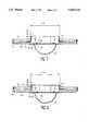
- FIG. 7is a first side elevation view, in partial section, of the mounting assembly for the dome camera module of FIG. 1;
- FIG. 8is a second side elevation view, in partial section, of the mounting assembly for the dome camera module of FIG. 1;
- FIG. 9is a block diagram of a dome camera surveillance system in accordance with the present invention.
- FIG. 10is a block diagram of a control subsystem for a dome camera module in the surveillance system according to the present invention.
- a dome camera modulefor monitoring a selected area.
- the dome camera module 10includes a camera 12 that captures real-time images of the selected area and transmits the images to a central monitoring station, or possibly to multiple monitoring stations, for viewing by an operator as shown in FIG. 9.
- a number of dome camera modules 10may be located at strategic locations throughout the monitored area to provide multiple views of the area to the central monitoring station.
- the dome camera module 10is installed into an existing ceiling in the area to be monitored.
- a hemispherical, translucent dome 14preferably formed of an acrylic material, extends below the ceiling to enclose the camera 12.
- the dome 14is preferably semi-transparent to permit the camera 12 to view the monitored area in a manner that is unobtrusive to persons present in the monitored area.
- a housing, generally designated 19,encloses the components of the dome camera module 10 above the ceiling.
- the housing 19has a stationary outer shell that includes a protective cover box 20 and a base 22.
- the base 22has an upwardly extending inner lip 23 that extends along the inner periphery of the base 22.
- a series of threaded holesare formed in the inner lip 23 of base 22.
- a plurality of horizontal support bars 24are formed at one end to be attached to the base 22. The other end of a support bar 24 is formed to be clipped onto a support span 30 of the ceiling grid to secure the dome camera module 10 to the ceiling.
- the housing 19includes an adjustable inner frame that is disposed within the outer shell of the housing 19 and that permits height adjustment of the dome 14 relative to the outer shell to allow for variations in thickness of ceiling panels or tiles.
- the outer shell of the housing 19is mounted above the ceiling tiles and thereafter, the inner frame is adjusted from below the ceiling.
- the inner frameincludes a plurality of interconnected walls 26 forming a structure that is connected to a peripheral horizontal support 28.
- the adjustable inner framecan be more readily understood with reference to FIGS. 7 and 8.
- FIGS. 7 and 8several walls 26 have a slot 88 formed therein that aligns with a threaded hole formed in the inner lip 23 of base 22.
- a screw or bolt 86attaches the wall 26 to the inner lip 23.
- the inner framecan be vertically adjusted by loosening screws 86 and moving the inner frame up or down.
- the dome camera module 10may be easily mounted in ceilings having various thicknesses or in a warped ceiling.
- FIG. 7shows mounting of the dome module 10 in a relatively thin ceiling 32a
- FIG. 8shows mounting of the dome module 10 in a thicker ceiling 32b.
- the dome 14, and a mating trim ring 84abut the ceiling 32.
- the dome 14is held in position with a ball stud and mating clip arrangement 82.
- the adjustable inner frame of the housing 19supports a pan and tilt assembly, generally designated 40, and a dome controller, which is embodied in circuit boards 16 and 18.
- the operation of the pan and tilt assembly 40can be better understood with reference to FIG. 2.
- the pan and tilt assembly 40includes a pan motor platform 27, mounted in fixed relation to the adjustable inner frame of housing 19. In the embodiment shown, the pan motor platform 27 mounts directly to the horizontal support 28. Rubber ring bumpers or spacers 29 are disposed between the platform 27 and the horizontal support 28 at the points of connection therebetween to provide vibration isolation between the housing 19 and the pan and tilt assembly 40.
- a pan motor 68which is preferably a stepper motor, is mounted to the pan motor platform 27. Rubber ring bumpers 25 are disposed between the pan motor 68 and the pan motor platform 27 to provide vibration isolation between the motor 68 and the housing 19.
- the pan motor 68includes a shaft that passes through the pan platform 27 and extends to the underside of the platform.
- a pulley 62is affixed to the pan-motor shaft.
- a timing belt 56shown in phantom, mechanically couples pulley 62 to drive a second pulley 60 which is rotatably mounted to the underside of the pan motor platform 27.
- the second pulley 60has an annular bearing (not shown) mounted in the center thereof to permit relatively unrestricted rotation of the pulley 60 when being driven by the pan motor 68. Furthermore, a hollow, eccentric shaft (not shown) is used for mounting the pulley 60 to the pan motor platform 27 and to permit tensioning of the timing belt 56.
- a tilt platform 47 in the form of a generally L-shaped yokeis supported from the pulley 60.
- a tilt motor 46preferably a stepper motor, is mounted on one leg of the tilt platform 47.
- the tilt motor 46has a shaft that extends through the tilt platform 47.
- a third pulley 64is affixed to the tilt motor shaft and is mechanically coupled to a fourth pulley 48 by a second timing belt 50, shown in phantom.
- An annular bearing and eccentric shaftare utilized to mount the pulley 48 to the tilt platform 47.
- shroud supports 52a and 52bare mounted to the tilt motor platform 47.
- An opaque, hemispherical shroud(not shown) is attached to the shroud supports 52a, 52b and moves with the tilt motor platform 47 during panning of the camera 12.
- the shroudincludes a vertical slot that corresponds to the tilt range of the camera 12 to permit viewing of the monitored area over the entire tilt range of the camera 12.
- a bracket 70is affixed to the camera 12 and to the pulley 48 for supporting the camera from pulley 48 such that the camera rotates concurrently with the pulley 48.
- a pin 44extends from one side of pulley 48 into engagement with a slot 42 formed in the tilt motor platform 47. This arrangement restricts the angular rotation of pulley 48, and consequently camera 12, to a range of approximately 100 degrees.
- the pin and slot arrangementalso provides a hard stop at either end of the tilt range.
- a slip ring 66is mounted to the pan motor platform 27.
- the slip ring 66provides electrical connections to the tilt motor 46 and camera 12 from the dome camera module controller and permits continuous panning of the camera 12 in either clockwise or counterclockwise direction. Because the pan motor 68 is mounted on the pan platform 27 electrical leads to the pan motor 68 need not pass through slip ring 66, thereby simplifying its construction.
- a further advantage realized by having the pan motor 68 located on the pan platform 27is that the weight and size of the moving components are substantially reduced, thereby resulting in increased response and speed in the panning operation for a given size of pan motor.
- a multi-conductor flex cable 38such as type FPC manufactured by AMP, is connected at one end to the camera 12 by means of a suitable connector 75. Cable 38 is connected at its other end to a second connector 76.
- the flex cable 38is positioned in surface-to-surface relation adjacent to the camera 12. The flex cable 38 is aligned to flex in conjunction with tilting of the camera 12. As shown in FIG. 5, when the camera 12 is in the full vertical position, the flex cable 38 is flexed to form an inverted "L" or "J". Whereas when the camera 12 is in the full horizontal position, as shown in FIG.
- the cable 38is flexed to form an elongated "C".
- Such an arrangementgreatly reduces the likelihood of damage to the flex cable 38.
- strain-reliefs 72 and 74are positioned adjacent connectors 75 and 76 respectively.
- a protective shield 78 mounted to the tilt platform 47 adjacent flex cable 38has a smooth surface to prevent cable wear resulting from repeated rubbing against the tilt platform 47 during upward and downward tilt movements of the camera 12.
- a dome camera surveillance systemlocated at a central monitoring location controls the overall operation of the camera surveillance system.
- a keyboard 102is connected to the video switcher 100 via a multi-conductor cable 101.
- the keyboard 102includes a joy stick, a plurality of function buttons, and an alphanumeric display.
- An operatoruses the keyboard 102 to select the display of images provided by one or more dome camera modules 10. For instance, the operator can select viewing of images provided by a particular dome camera module 10 or can select sequential viewing of images provided by multiple dome camera modules on one or more video monitors.
- the operatorcan also control the positioning of the camera within any dome camera module 10 using the joy stick. To do so the operator initially selects a particular dome camera module 10 using the keyboard 102. During selection, the display on the keyboard shows the indicia that identify the selected dome camera. After dome selection is completed, camera positioning may be controlled using the keyboard joy stick. For example, if the operator moves the joy stick to the left or right, the pan motor 68 is activated inside the dome camera module, thereby causing the camera to pan left or right. Similarly, if the operator moves the joy stick fore or aft, the tilt motor 46 is activated, resulting in the camera tilting up or down. Further, the operator may control certain camera functions, such as focusing, zooming and white balance, from the keyboard.
- the operatorcan select automatic operation of one or more camera functions to provide enhanced images of the monitored area and to simplify the task of monitoring the area under surveillance.
- the various features of the camera surveillance system relating to control of the camera functionsare disclosed in a commonly-owned, co-pending application entitled “Video Surveillance System” filed concurrently herewith and incorporated herein by reference, now U.S. Pat. No. 5,517,236, issued May 14, 1996.
- the video switcher 100samples the output of the keyboard 102 at periodic intervals and transmits a control message based on the keyboard output to all dome camera modules on the system.
- the video switcheris connected to a signal distribution unit 104 that converts the TTL signal sent by the video switcher 100 over line 106 into a balanced signal.
- the balanced signalis transmitted via twisted pair cable 108 to the dome controllers 110, 112, 114.
- the twisted-pair cable 108runs directly to each dome controller from the signal distribution unit 104 or, alternatively, is daisy-chained from one dome controller to another.
- the control message sent to the dome controllers 110, 112, 114includes an address that uniquely identifies a particular dome controller. Only the dome controller having a matching address processes the control message. All other domes disregard the broadcast control message.
- Each control messagealso contains keyboard status information, which includes camera control commands. Such information includes joy stick horizontal position (pan direction and pan speed), joy stick fore and aft position (tilt direction and tilt speed) and camera control, such as zoom, focus and white balance adjustment.
- Communication between the video switcher 100 and the dome controllers 110, 112, 114is unidirectional.
- full-duplex communication using a serial communication protocol, such as RS-232can be utilized so that the video switcher 100 receives camera status information from the dome controllers.
- a separate video signalis transmitted from each of the dome controllers 110, 112, 114 along signal lines 111, 113, 115 and is received by the video switcher 100.
- the operatorcontrols the video signal path through the switcher 100 to one or more video monitors.
- FIG. 9shows three video monitors 120, 122, 124 that receive video signals from the video switcher 100 via video cables 121, 123, 125. In that configuration, images from any of the dome controllers 110, 112, 114 can be displayed on any of the monitors 120, 122, 124.
- a dome controller 110which includes a MC68HC16 micro-controller 130 of the type manufactured by Motorola Incorporated.
- the micro-controller 130manages the functions of the dome camera module 10. Such functions are dictated by commands sent from the video-switcher 100 located at the remote central monitoring station.
- the micro-controller 130executes a program that is stored in a non-volatile memory, embodied as an EPROM 134.
- the micro-controller 130has internal data registers for storing frequently-changed and run-time variables.
- An EEPROM 136is utilized for storing system configuration and setup variables because such a device retains its data when power to the dome controller 10 is turned off.
- a local test selector 131is included on the dome controller 110.
- the selector 131which has a push button and a four-digit thumbwheel, serves two primary functions.
- a service techniciancan use the local test selector 131 for diagnostic servicing by dialing in a diagnostic code on the thumbwheel and then activating the push button to execute the corresponding function.
- the techniciancan set the thumbwheel for a tilt motor downward movement and then activate the push button to move the tilt motor 46 in the selected direction. In this manner the technician is able to diagnose, service, or test the dome camera module 10 without requiring activation of dome camera module functions from the central monitoring station, i.e., through keyboard 102.
- the local test selector 131is used to assign an address to the dome controller 110. More specifically, the thumbwheel of the local test selector 131 is set to a desired 4-digit address. Subsequently, when control messages are sent to the dome controller 110, the address that is included in the prefix of the control message is compared against the setting on the local test selector.
- the dome controller 110includes a communication receiver 132 that receives a control message from the video switcher 100 in a serial :format and converts it to a parallel format. The control message is then sent to the micro-controller 130 for processing. The micro-controller 130 determines whether the address present in the control message matches the address of the dome controller 110. If there is no match, then the micro-controller 130 ignores the remainder of the control message. If, however, the control message address matches the dome camera module address, the control message is processed by the micro-controller 130.
- the dome controller 110includes a means for precisely controlling movements of the pan motor 68 and the tilt motor 46.
- a pan motor control circuit 142 and tilt motor control circuit 144are provided for controlling the motors 68 or 46, respectively.
- pan motor 68 and tilt motor 46are stepper motors and each is formed to have 200 full steps, each step corresponding to 1.8 degrees of rotation. However, intermediate step positions are selected by utilizing motor controllers 142 and 144 to micro-step the motors. Each full step is divided into 125 micro-steps to provide a total of 25,000 micro-steps per revolution. Although the total number of micro-steps is the same for the pan motor 68 and tilt motor 46, the amount of angular panning movement of the camera per step differs from the amount of angular tilting movement per step. In the case of the pan drive system a ratio of 5:1 is used between pulley 60 and pulley 62.
- the camerapans 0.00288 degrees.
- a ratio of 2:1is used between the pulley 48 and pulley 64.
- the cameratilts 0.0072 degrees.
- the pan motor controller 142 and the tilt motor controller 144also include means for regulating current flow to the motors 68 and 46 in order to reduce power consumption when the motors are in an idling or slow-moving state.
- a 12-bit digital-to-analog converter (DAC) in controller 110is programmed by the micro-controller 130 to set the current level for each of motors 68 and 46.
- the maximum current level for each of the motors 68 and 46is 1 amp. It has been found that a setting of 35% of the maximum current level is suitable during idling periods, a setting of 50% of the maximum current level is suitable during steady motor travel, and a setting of 75% of the maximum current level is suitable for acceleration and deceleration of the motors.
- the micro-controller 130continuously tracks the camera position respective to the home pan and tilt positions.
- the starting or home positions of the motors 68 and 46are determined by a homing sequence performed with respect to each motor.
- the homing sequenceis executed by the micro-controller 130 during initial power-up, during restart after a power-failure or after receiving a homing message from the central monitoring station.
- the homing of the pan motor 68is initiated by activating the pan motor 68.
- An optical switch 54is monitored by the micro-controller 130. As shown in FIG. 3, the optical switch 54 is mounted to the pan motor platform 27 and a flag 58 is affixed to the outer perimeter of the pulley 60. When the pulley 60 rotates the flag 58 eventually aligns with the optical switch and blocks the sensor in optical switch 54 for a brief period of time. At all other times the sensor in optical switch 54 remains unblocked. When the sensor in optical switch 54 is blocked, the home position for the pan motor 68 is calibrated by the micro-controller 130.
- the pan motor 68 positioncan thereafter be tracked by counting the number of steps issued to the pan motor 68 by the pan motor controller 142. In that manner, the pan motor 68 can be stopped, restarted, or operated continuously, and its location is continuously tracked relative to the home position.
- Such open-loop controleliminates the need for sensors, such as potentiometers or encoders, to determine the current pan position of the camera 12.
- the home position of the pan motor 68can be recalibrated whenever the sensor of optical switch 54 is blocked by the flag 58. For instance, if the pan motor 68 is in a continuous panning mode of operation, recalibration of the pan motor home position occurs once for each revolution of pulley 60. Recalibration in this manner prevents any error buildup in tracking the pan position of the camera 12.
- the homing sequence for the tilt motor 46differs from that of the pan motor 68. Rather than utilizing an optical sensor, which would require additional connections through the slip ring 66, a mechanical stop is used to calibrate the home position of the tilt motor 46. As shown in FIG. 3, the pin 44 extending from pulley 48 engages with the curved slot 42 formed in tilt platform 47. As the pulley 48 rotates in response to activation of tilt motor 46, the pin 44 travels within slot 42 to limit angular displacement of the camera. The tilt motor 46 is run in an open-loop mode and there is no feedback to the micro-controller 130 to inform it when the upper-most tilt position has been reached.
- the tilt motor 46is activated so that the camera 12 moves to a generally horizontal position, as shown in FIG. 6.
- the tilt motor 46is activated for a period of time sufficient to ensure that the camera 12 travels to the full horizontal position.
- the pin 44contacts one end of the slot 42 and causes the tilt motor 46 to slip for a brief period.
- the tilt motor 46is operated in reverse for a selected number of steps, thereby establishing the tilt motor home position. Similar to the pan motor 68, subsequent movement of the tilt motor is tracked by counting steps from the home position.
- a lens controller 154 and camera controller 156are included in the dome camera module 10.
- the lens controller 154 and camera controller 156each receive commands from the central monitoring station through the micro-controller 130 or directly from the micro-controller 130. Communication between the lens controller 154 and the micro-controller 130 is effected through a bi-directional synchronous communication link 153. Whereas communication between the micro-controller 130 and the camera controller 156 is effected through a bi-directional asynchronous communication link 155.
- Examples of commands sent to the lens controller 154include a manual focus command .and an auto-focus command from the central monitoring station and a focus positioning command sent by the micro-controller 130 based on tilt motor and pan motor positioning.
- Examples of commands to the camera controller 156include a manual white balance and auto-white balance command from the central monitoring station, as well as a white balance level command from the micro-controller 130 based on the positions of the tilt and pan motors.
- Poweris provided to the dome controller 110, lens controller 154, camera controller 156, pan motor 68, and tilt motor 46 from a power supply 140 located in the dome controller 110.
- a power transformer 138steps-down the AC line voltage from an external source to the power supply.
- the AC power conductoris fed through a conduit 34 into a separate wiring box 36, which houses the transformer 138, as shown in FIG. 1.
- the micro-controller 130continuously tracks the position of the pan motor 68 and tilt motor 46. The most current position is stored in data registers located within micro-controller 130. Several automated features can be activated by the micro-controller 130 based on pan and tilt motor positions.
- An auto-pivot featureis provided which is especially useful when viewing a person walking down a hallway or aisle and passing underneath the dome camera module 10.
- the micro-controller 130monitors the tilt motor position and the tilt motor speed that is selected by the operator using the keyboard joy stick.
- the video switcher 100periodically transmits a tilt motor direction and speed signal to the dome controller 110. If the camera position is determined to be in a generally vertical position, i.e., the camera is capturing images directly below the dome camera module 10, and if the selected tilt motor speed is greater than a selected threshold auto-pivot speed, then the following sequence is automatically executed by the micro-controller 130.
- the tilt motor 46is deactivated just prior to pin 44 contacting the end of the slot 42.
- the pan motor 68is automatically activated to pan 180 degrees and then deactivated.
- the tilt motor 46is activated to cause the camera 12 to travel from the full vertical position toward the horizontal position.
- the tilt motor 46is in a generally vertical position, but the tilt motor speed is less than the threshold auto-pivot speed, then the auto-pivot function is not executed by the micro-controller 130. Instead, the tilt motor 46 is deactivated when the camera 12 reaches the full vertical position. The tilt motor 46 remains in this position until a tilt speed signal exceeding the threshold auto-pivot speed is selected with the joy stick. In this manner, if a person walking down a hallway or aisle, slows down and stops directly below the dome camera module 10, the tilt motor 46 can be stopped to hold the camera 12 at its vertical position without inadvertently activating the auto-pivot function.
- the tilt motor 46can simply be reversed to so that the person can be continuously viewed. However, if the person continues down the hall in the original direction, the pan motor can be manually activated to pivot the camera or the tilt motor speed can be increased to cause execution of the auto-pivot function as described above.
- the auto-pivot sequencemay be alternatively activated upon expiration of a selected time-out period.
- the tilt motor 46is determined to be in a generally vertical position, the tilt motor 46 is deactivated. Thereafter, the selected tilt motor speed is monitored. If the tilt motor speed is maintained at a selected level for a duration exceeding the selected time-out period, the auto-pivot sequence is executed.
- a further alternative of the auto-pivot functioncombines monitoring of the tilt motor speed and the time-out period. In the combined mode, a tilt motor speed exceeding the threshold auto-pivot speed and the expiration of the selected time-out period is required to initiate the auto-pivot sequence.
- EEPROM 136 of dome controller 110stores a set of pre-positions.
- a pre-positionis a set of variables that defines a camera state including its pan position, tilt position, and camera settings, such as zoom location, focus location, and white balance level.
- the micro-controller 130reads pre-position information from the EEPROM 136 and activates the pan motor 68 and tilt motor 46 to reorient the camera from a first location to the location defined by the pre-position.
- the micro-controller 130sends lens control and camera control messages to the lens controller 154 and camera controller 156, respectively, which in turn perform the necessary operations to achieve the preposition lens and camera settings.
- the present inventionalso includes a tour feature, which "plays back" a recorded sequence of pre-positions.
- the pre-positionsmay be recorded by various methods. In one method, the operator positions the camera 12 by activating the pan motor 68 and the tilt motor 46 until the desired viewing location is reached. Next, the operator adjusts the camera and lens settings as necessary to obtain the best image of the location being viewed. For instance, the operator can select a close-up view by activating a keyboard zoom button and then adjust the camera focus by activating a focus button. After all the adjustments are completed, a pre-position number is selected via the keyboard.
- a command to set the selected pre-positionis initiated using the keyboard, at which time the pre-position set command and the selected pre-position number are transmitted to the dome controller 110 to instruct the controller to store the current camera position and settings in EEPROM 136. As many as 60 pre-positions can be recorded in this manner. Subsequently, the operator can select play back of the stored prepositions in a sequential manner. Alternatively, the operator may select a subset of the pre-positions for play back in any desired order.
- An alternate tour moderequires that the operator continuously position the camera by manipulating the joy stick and change camera settings as desired. While the operator is “recording" in this manner, the keyboard status (e.g. position of the joy stick) is monitored by the video switcher 100 at 50 millisecond increments and is stored as a keyboard command in a memory located on the video switcher 100. Thereafter, the operator can select play back of the stored keyboard commands, at which time the video switcher retrieves the commands stored in the memory and sends messages to the dome controller 110 as if the operator were directly controlling camera movement and camera settings.
- the keyboard statuse.g. position of the joy stick
- the micro-controller 130can also be programmed to automatically adjust pan and tilt motor speeds, a function referred to as speed scaling.
- Speed scalingis a method for accurately tracking a moving target based on its distance from the camera 12. For instance, if a person located a long distance from the camera is being monitored, and the camera lens is set for wide angle viewing, relatively slow panning and tilting movements are required to track the person. If the person is but a few feet from the camera, the speed of panning and tilting movements must be increased to accurately track the person. In addition, as the person moves closer to or farther from the camera, the speed of panning and tilting is automatically adjusted to compensate for the change in distances. For example, the panning speed may be set for a current zoom position. Thereafter, as the zoom position changes, the panning speed is changed proportionately. In addition, pan motor speed may be scaled as follows:
- pan and tilt motor speedsmay be scaled based on the camera's auto-focus distance or on the camera's tilt position.
- the micro-controller 130can also be programmed to calculate the shortest path between a current camera position and a desired camera position. When the micro-controller 130 is so programmed and a change in camera position is required, the micro-controller 130 compares the current pan position to the desired pan position and the pan motor 68 is then activated to move the camera 12 in the direction of the shorter path, i.e., clockwise or counterclockwise.
Landscapes
- Engineering & Computer Science (AREA)
- Multimedia (AREA)
- Signal Processing (AREA)
- Physics & Mathematics (AREA)
- General Physics & Mathematics (AREA)
- Manufacturing & Machinery (AREA)
- Microelectronics & Electronic Packaging (AREA)
- Studio Devices (AREA)
- Closed-Circuit Television Systems (AREA)
Abstract
Description
Speed=((Z.sub.pos /Z.sub.max)*(1-S.sub.min))+S.sub.min
Claims (12)
Priority Applications (6)
| Application Number | Priority Date | Filing Date | Title |
|---|---|---|---|
| US08/263,918US5627616A (en) | 1994-06-22 | 1994-06-22 | Surveillance camera system |
| KR1019950003114AKR100314967B1 (en) | 1994-06-22 | 1995-02-18 | Surveillance camera system and monitoring method using the system |
| DE69515265TDE69515265T2 (en) | 1994-06-22 | 1995-06-21 | SURVEILLANCE CAMERA SYSTEM |
| PCT/IB1995/000500WO1995035624A1 (en) | 1994-06-22 | 1995-06-21 | Surveillance camera system |
| EP95920194AEP0714579B1 (en) | 1994-06-22 | 1995-06-21 | Surveillance camera system |
| JP50189796AJP3907202B2 (en) | 1994-06-22 | 1995-06-21 | Surveillance camera system |
Applications Claiming Priority (1)
| Application Number | Priority Date | Filing Date | Title |
|---|---|---|---|
| US08/263,918US5627616A (en) | 1994-06-22 | 1994-06-22 | Surveillance camera system |
Publications (1)
| Publication Number | Publication Date |
|---|---|
| US5627616Atrue US5627616A (en) | 1997-05-06 |
Family
ID=23003805
Family Applications (1)
| Application Number | Title | Priority Date | Filing Date |
|---|---|---|---|
| US08/263,918Expired - LifetimeUS5627616A (en) | 1994-06-22 | 1994-06-22 | Surveillance camera system |
Country Status (6)
| Country | Link |
|---|---|
| US (1) | US5627616A (en) |
| EP (1) | EP0714579B1 (en) |
| JP (1) | JP3907202B2 (en) |
| KR (1) | KR100314967B1 (en) |
| DE (1) | DE69515265T2 (en) |
| WO (1) | WO1995035624A1 (en) |
Cited By (104)
| Publication number | Priority date | Publication date | Assignee | Title |
|---|---|---|---|---|
| US5850579A (en)* | 1997-06-09 | 1998-12-15 | Addco, Inc. | Pan/tilt support with concentric drive shafts |
| WO1999005857A1 (en)* | 1997-07-21 | 1999-02-04 | Bauer Will N | Virtual positioning media control system |
| EP0931972A1 (en)* | 1998-01-26 | 1999-07-28 | Matsushita Electric Industrial Co., Ltd. | Parts-mounted member and method of mounting parts |
| US5991429A (en)* | 1996-12-06 | 1999-11-23 | Coffin; Jeffrey S. | Facial recognition system for security access and identification |
| US6009233A (en)* | 1995-08-31 | 1999-12-28 | Sony Corporation | Apparatus and method for recording and reproducing a video signal with camera setting data |
| WO2000024200A1 (en)* | 1998-10-22 | 2000-04-27 | Sensormatic Electronics Corporation | Controlling movement of video surveillance cameras |
| US6124892A (en)* | 1996-03-15 | 2000-09-26 | Canon Kabushiki Kaisha | Panhead device for movably supporting an apparatus |
| US6215519B1 (en) | 1998-03-04 | 2001-04-10 | The Trustees Of Columbia University In The City Of New York | Combined wide angle and narrow angle imaging system and method for surveillance and monitoring |
| US6226035B1 (en) | 1998-03-04 | 2001-05-01 | Cyclo Vision Technologies, Inc. | Adjustable imaging system with wide angle capability |
| US6333759B1 (en) | 1999-03-16 | 2001-12-25 | Joseph J. Mazzilli | 360 ° automobile video camera system |
| KR100314967B1 (en)* | 1994-06-22 | 2002-02-28 | 펄지니 마가렛 | Surveillance camera system and monitoring method using the system |
| US6392693B1 (en)* | 1998-09-03 | 2002-05-21 | Matsushita Electric Industrial Co., Ltd. | Monitoring video camera apparatus |
| US20020061134A1 (en)* | 2000-11-17 | 2002-05-23 | Honeywell International Inc. | Object detection |
| USD457904S1 (en) | 2001-03-30 | 2002-05-28 | Pelco | Heavy duty pendant for a dome camera system |
| WO2002003700A3 (en)* | 2000-06-30 | 2002-05-30 | Sensormatic Electronics Corp | Integrated enclosure and controller for video surveillance camera |
| US20020102101A1 (en)* | 2001-01-30 | 2002-08-01 | Philips Electronics North America Corporation | Camera system and method for operating same |
| US20020125435A1 (en)* | 2001-01-19 | 2002-09-12 | Cofer Darren D. | Method and apparatus for detecting objects |
| US20020140850A1 (en)* | 2001-03-29 | 2002-10-03 | Pelco | Heavy duty pendant with dome guard for dome camera system |
| US20020140819A1 (en)* | 2001-04-02 | 2002-10-03 | Pelco | Customizable security system component interface and method therefor |
| US20030021602A1 (en)* | 2001-07-27 | 2003-01-30 | Pelco | Universal surveillance camera holder and adaptor |
| US6628338B1 (en)* | 1998-07-08 | 2003-09-30 | Elbex Video Ltd. | Direct drive electric motor apparatus incorporating slip ring assembly |
| US20030185556A1 (en)* | 2002-03-28 | 2003-10-02 | Pelco | Retractable camera mounting mechanism |
| US20030194230A1 (en)* | 2002-04-10 | 2003-10-16 | Matsushita Electric Industrial Co., Ltd. | Rotation device with an integral bearing |
| EP1381002A1 (en)* | 2002-07-08 | 2004-01-14 | Matsushita Electric Industrial Co., Ltd. | Surveillance camera apparatus |
| FR2842306A1 (en)* | 2002-07-12 | 2004-01-16 | Egg Solution Optronics | Wide angle electromagnetic wave acquisition sensor system has part coated infra red and optical reflector with filtering and processing to control zoom camera |
| US20040012674A1 (en)* | 2002-07-08 | 2004-01-22 | Jouji Wada | Surveillance camera apparatus |
| US20040021785A1 (en)* | 2000-06-22 | 2004-02-05 | Yacov Pshtissky | Dome housed video camera assembly with 180 degree tilt motion |
| US20040027541A1 (en)* | 2001-01-11 | 2004-02-12 | Ludwig Angerpointner | Device for rotating a body about two axes |
| US20040041909A1 (en)* | 2002-09-02 | 2004-03-04 | Japan Servo Co., Ltd. | Method of surveillance camera by using rotary electric machine |
| US20040057717A1 (en)* | 2002-09-20 | 2004-03-25 | Arbuckle James F. | Camera mounting enclosure and method of installation |
| US20040075739A1 (en)* | 2002-09-05 | 2004-04-22 | Jyoji Wada | Surveillance camera apparatus |
| US20040100563A1 (en)* | 2002-11-27 | 2004-05-27 | Sezai Sablak | Video tracking system and method |
| EP1274231A3 (en)* | 2001-07-06 | 2004-06-30 | plettac AG | Method and device for controlling pan and tilt movements of a camera |
| US20040146184A1 (en)* | 2000-11-17 | 2004-07-29 | Hamza Ridha M | Object detection |
| US6793414B2 (en)* | 2000-03-31 | 2004-09-21 | Canon Kabushiki Kaisha | Movable camera apparatus with a pan head |
| USD497927S1 (en) | 2003-06-02 | 2004-11-02 | Pelco | Camera mount and enclosure |
| US20040223062A1 (en)* | 2003-05-05 | 2004-11-11 | Richard Pettegrew | Pan and tilt camera system |
| US20040256541A1 (en)* | 2001-01-19 | 2004-12-23 | Honeywell International Inc. | Method and apparatus for detecting objects using structured light patterns |
| EP1134979A4 (en)* | 1999-09-30 | 2005-01-05 | Matsushita Electric Industrial Co Ltd | MONITORING CAMERA THAT CAN RECORD AN OPERATING HISTORY, AND A RECORDING METHOD OF AN OPERATING HISTORY |
| US6853404B1 (en)* | 1998-05-11 | 2005-02-08 | Foveon, Inc. | Electronic view camera for tripod mounting |
| US20050057656A1 (en)* | 2003-09-12 | 2005-03-17 | Logitech Europe S.A. | Pan and tilt camera |
| US20050179782A1 (en)* | 2004-02-13 | 2005-08-18 | Canon Kabushiki Kaisha | Image capturing system and control method of the same |
| US20050185058A1 (en)* | 2004-02-19 | 2005-08-25 | Sezai Sablak | Image stabilization system and method for a video camera |
| US20050200751A1 (en)* | 2004-03-12 | 2005-09-15 | Weaver Dennis L. | Mounting assembly for camera |
| US20050243170A1 (en)* | 2004-04-14 | 2005-11-03 | Chang Pao C | Speed dome |
| US20050259984A1 (en)* | 2004-05-19 | 2005-11-24 | Wright Richard R | Adjustable camera with belt tensioning apparatus |
| US20050270371A1 (en)* | 2004-06-02 | 2005-12-08 | Sezai Sablak | Transformable privacy mask for video camera images |
| US20050270372A1 (en)* | 2004-06-02 | 2005-12-08 | Henninger Paul E Iii | On-screen display and privacy masking apparatus and method |
| US20050275723A1 (en)* | 2004-06-02 | 2005-12-15 | Sezai Sablak | Virtual mask for use in autotracking video camera images |
| US20050280707A1 (en)* | 2004-02-19 | 2005-12-22 | Sezai Sablak | Image stabilization system and method for a video camera |
| US6992723B1 (en) | 2000-06-30 | 2006-01-31 | Sensormatic Electronics Corporation | Integrated enclosure for video surveillance camera |
| US20060056056A1 (en)* | 2004-07-19 | 2006-03-16 | Grandeye Ltd. | Automatically expanding the zoom capability of a wide-angle video camera |
| US20060075448A1 (en)* | 2004-10-01 | 2006-04-06 | Logitech Europe S.A. | Mechanical pan, tilt and zoom in a webcam |
| US20060133787A1 (en)* | 2003-02-18 | 2006-06-22 | Matsushita Electric Industrial Co., Ltd. | Imaging system |
| US20060256201A1 (en)* | 2005-05-10 | 2006-11-16 | Ge Security, Inc. | Methods and systems for controlling camera movement |
| US7151562B1 (en)* | 2000-08-03 | 2006-12-19 | Koninklijke Philips Electronics N.V. | Method and apparatus for external calibration of a camera via a graphical user interface |
| US7161624B1 (en)* | 1999-04-16 | 2007-01-09 | Fujinon Corporation | Remote control pan head system |
| US20070019947A1 (en)* | 2005-07-25 | 2007-01-25 | Tsutomu Shimada | Device mounting apparatus, adjustment JIG, and image pickup apparatus with adjustment mechanism |
| US20070053681A1 (en)* | 2005-09-02 | 2007-03-08 | Pelco | Camera support and mounting assembly |
| KR100716306B1 (en) | 2006-11-14 | 2007-05-08 | 주식회사 지.피 코리아 | Forest Fire Monitoring System |
| US20070127912A1 (en)* | 2005-12-06 | 2007-06-07 | Jones Theodore L | Surveillance camera gimbal mechanism |
| WO2007071291A1 (en)* | 2005-12-22 | 2007-06-28 | Robert Bosch Gmbh | Arrangement for video surveillance |
| US20070189764A1 (en)* | 2006-02-13 | 2007-08-16 | Hewlett-Packard Development Company Lp | Camera mount |
| US20080068459A1 (en)* | 2006-09-14 | 2008-03-20 | Hon Hai Precision Industry Co., Ltd. | Apparatus and method for controlling video surveillance system |
| US20080111891A1 (en)* | 2006-11-13 | 2008-05-15 | Kazuyuki Kurita | Remote-controlled platform system |
| US20080136910A1 (en)* | 2006-12-07 | 2008-06-12 | Sensormatic Electronics Corporation | Method and apparatus for video surveillance system field alignment |
| US20080159732A1 (en)* | 2006-12-29 | 2008-07-03 | Stuart Young | Positioning device |
| US20080158355A1 (en)* | 2006-08-10 | 2008-07-03 | Sanyo Electric Co., Ltd. | Surveillance camera |
| US20080158371A1 (en)* | 2006-12-29 | 2008-07-03 | The Boeing Company | Dual Loop Stabilization of Video Camera Images |
| US20080204560A1 (en)* | 2007-02-19 | 2008-08-28 | Axis Ab | Method for compensating hardware misalignments in a camera |
| US20080267612A1 (en)* | 2006-02-16 | 2008-10-30 | Harvey William B | Miniaturized turret-mounted camera assembly |
| US20080308706A1 (en)* | 2007-06-15 | 2008-12-18 | Jeffrey Lane | Imaging device mounting apparatus |
| RU2345501C2 (en)* | 2006-12-27 | 2009-01-27 | Общество с Ограниченной Ответственностью "БИК-Информ" | Rotary device for field supervision chamber |
| US20090028536A1 (en)* | 2007-07-24 | 2009-01-29 | Honeywell International, Inc. | Apparatus and method for measuring an acceleration to determine a camera dome's required motor holding current |
| US20090026996A1 (en)* | 2007-07-26 | 2009-01-29 | Toshihide Nakane | Pulse motor control device, control method, control program, and imaging apparatus |
| US20090032683A1 (en)* | 2006-12-12 | 2009-02-05 | The University Of Western Ontario | Flexible bioelectronic photodetector and imaging arrays based on bacteriorhodopsin (BR) thin films |
| US20090073388A1 (en)* | 2004-05-06 | 2009-03-19 | Dumm Mark T | Camera control system and associated pan/tilt head |
| ES2316237A1 (en)* | 2006-05-18 | 2009-04-01 | Alina Lopez Hernandez | Remote television system (Machine-translation by Google Translate, not legally binding) |
| US20090141143A1 (en)* | 2007-11-29 | 2009-06-04 | Axis Ab | Network camera |
| US20090256912A1 (en)* | 2008-04-10 | 2009-10-15 | Yoav Rosenberg | Method and a System for False Alarm Reduction in Motion Detection by Scanning Cameras |
| US20100128122A1 (en)* | 2008-11-26 | 2010-05-27 | Robert Bosch Gmbh | Camera having a slip ring and pan-tilt mechanism |
| CN101179708B (en)* | 2007-10-31 | 2010-06-23 | 天津市亚安科技电子有限公司 | Circuit of S video and compound video simultaneous output suitable for platform camera |
| CN101166239B (en)* | 2006-10-19 | 2010-06-23 | 罗伯特·博世有限公司 | Image processing system and method for improving repeatability |
| US20100272316A1 (en)* | 2009-04-22 | 2010-10-28 | Bahir Tayob | Controlling An Associated Device |
| WO2011082185A1 (en) | 2009-12-30 | 2011-07-07 | Robert Bosch Gmbh | Confined motion detection for pan-tilt cameras employing motion detection and autonomous motion tracking |
| US20110175999A1 (en)* | 2010-01-15 | 2011-07-21 | Mccormack Kenneth | Video system and method for operating same |
| WO2012023844A1 (en)* | 2010-08-20 | 2012-02-23 | Mimos Berhad | System and method for multiple exposure imaging |
| WO2012048138A1 (en) | 2010-10-07 | 2012-04-12 | Robert Bosch Gmbh | Surveillance camera position calibration device |
| US8174612B1 (en)* | 2008-08-12 | 2012-05-08 | Steve Koehler | Imaging device |
| US20120113215A1 (en)* | 2009-06-25 | 2012-05-10 | Weihai Future Robot Co., Ltd | Head bracket |
| US8497935B2 (en) | 2004-08-26 | 2013-07-30 | Robert Bosch Gmbh | Rotatable camera system including infrared communications links |
| US20130258102A1 (en)* | 2012-03-30 | 2013-10-03 | Hon Hai Precision Industry Co., Ltd. | Monitoring camera device with wireless control |
| US8624976B2 (en) | 2007-04-13 | 2014-01-07 | Axis Ab | Supporting continuous pan rotation in a pan-tilt camera |
| WO2014071291A3 (en)* | 2012-11-02 | 2014-06-26 | Strongwatch Corporation, Nevada C Corp | Wide area imaging system and method |
| CN103968217A (en)* | 2013-01-29 | 2014-08-06 | 三星泰科威株式会社 | Rotating support assembly and photographing apparatus comprising the same |
| US8860780B1 (en) | 2004-09-27 | 2014-10-14 | Grandeye, Ltd. | Automatic pivoting in a wide-angle video camera |
| US9309006B2 (en) | 2010-06-29 | 2016-04-12 | Aerovironment, Inc. | UAV payload module camera assembly and retraction mechanism |
| US9329458B1 (en) | 2004-05-06 | 2016-05-03 | Mark T. Dumm | Pan/tilt head with tilt range extender |
| US20160269647A1 (en)* | 2014-09-30 | 2016-09-15 | Korea Research Institute Of Standards And Science | High-speed and high-resolution pan-tilt device capable of changing height |
| RU167861U1 (en)* | 2016-07-26 | 2017-01-20 | Акционерное Общество "Завод "Фиолент" | Slewing ring |
| WO2017175059A1 (en)* | 2016-04-04 | 2017-10-12 | Sgs Sa | Testing systems capable of providing real-time certification |
| US10162352B2 (en) | 2013-05-13 | 2018-12-25 | The Boeing Company | Remotely operated mobile stand-off measurement and inspection system |
| US10394234B2 (en) | 2017-12-18 | 2019-08-27 | The Boeing Company | Multi-sensor safe path system for autonomous vehicles |
| US11268651B2 (en)* | 2019-09-19 | 2022-03-08 | Anduril Industries, Inc. | Pan tilt unit |
Families Citing this family (12)
| Publication number | Priority date | Publication date | Assignee | Title |
|---|---|---|---|---|
| JP2000002913A (en) | 1998-06-15 | 2000-01-07 | Matsushita Electric Ind Co Ltd | Surveillance camera rotation control device |
| JP2000050238A (en) | 1998-07-27 | 2000-02-18 | Matsushita Electric Ind Co Ltd | Surveillance camera device |
| KR100335967B1 (en)* | 1999-07-09 | 2002-05-09 | 김운용 | Pan/tilt camera |
| KR100383735B1 (en)* | 2000-10-13 | 2003-05-14 | 주식회사 씨티앤컴 | Apparatus framing of monitoring Camera |
| DE10353981A1 (en)* | 2003-11-19 | 2005-06-09 | Sick Ag | camera system |
| WO2006028247A1 (en)* | 2004-09-10 | 2006-03-16 | Pioneer Corporation | Video shooting system, video shooting device and video shooting method |
| KR101353473B1 (en)* | 2009-06-11 | 2014-01-22 | 삼성테크윈 주식회사 | Monitoring camera, method for controlling the same, and recording medium storing program to execute the method |
| KR101293602B1 (en)* | 2010-04-12 | 2013-08-13 | 주식회사 영국전자 | Furnace Monitoring System and Method |
| JP2012088450A (en)* | 2010-10-18 | 2012-05-10 | Canon Inc | Imaging apparatus |
| EP2771607B1 (en)* | 2011-10-27 | 2015-06-10 | Robert Bosch GmbH | Adjustment arrangement |
| KR101336608B1 (en)* | 2012-04-19 | 2013-12-05 | 서울과학기술대학교 산학협력단 | The apparatus of large sized monitoring camera with pan tilt zoom |
| JP7280976B2 (en)* | 2019-05-03 | 2023-05-24 | トヨタ モーター ヨーロッパ | Image acquisition means for object tracking |
Citations (30)
| Publication number | Priority date | Publication date | Assignee | Title |
|---|---|---|---|---|
| US1945112A (en)* | 1931-02-07 | 1934-01-30 | Hogan George Francis | Photographic equipment |
| US2415563A (en)* | 1943-04-22 | 1947-02-11 | Fairchild Camera Instr Co | Rotating camera mount |
| US3398664A (en)* | 1965-11-26 | 1968-08-27 | Radio Broadcasting Company | Combined television and photographic machine |
| US3437753A (en)* | 1965-12-07 | 1969-04-08 | Coburn Mfg Co Inc | Pan and tilt television camera |
| US3720147A (en)* | 1971-04-29 | 1973-03-13 | Setronics Corp | Mask for surveillance camera |
| US3732368A (en)* | 1971-04-23 | 1973-05-08 | Telesphere Technology | Surveillance unit for scanning an area under surveillance |
| US3739703A (en)* | 1970-03-09 | 1973-06-19 | G Behles | Concealment of cameras for observational purposes |
| US4058831A (en)* | 1976-09-08 | 1977-11-15 | Lectrolarm Custom Systems, Inc. | Panoramic camera scanning system |
| US4080629A (en)* | 1974-11-11 | 1978-03-21 | Photo-Scan Limited | Camera and housing |
| US4160999A (en)* | 1978-04-05 | 1979-07-10 | Claggett Joseph H | Mounting arrangement for a television monitoring camera |
| US4233634A (en)* | 1979-06-22 | 1980-11-11 | Adams Jay W | Video camera with adjustable mount and counterbalance |
| US4499490A (en)* | 1982-05-10 | 1985-02-12 | Morgan Jack B | Scanning apparatus with video camera |
| US4654703A (en)* | 1985-11-22 | 1987-03-31 | Viera William E | Video camera surveillance system |
| US4655567A (en)* | 1986-03-07 | 1987-04-07 | Morley John D | Remotely manipulatable panning and tilting mount for video cameras and the like and method of manipulating a camera |
| US4673268A (en)* | 1986-05-12 | 1987-06-16 | Wheeler Ernest E | Pan and tilt mount |
| US4833534A (en)* | 1988-02-19 | 1989-05-23 | Sensormatic Electronics Corporation | Surveillance assembly having enhanced shielding and reduced size |
| US4847543A (en)* | 1988-04-08 | 1989-07-11 | Ultimatte Corporation | Motion control drive interface |
| US4855823A (en)* | 1988-05-05 | 1989-08-08 | Applied Engineering Products Co. | Imaging assembly and mounting for surveillance viewing under remote control |
| US4901146A (en)* | 1988-05-05 | 1990-02-13 | Applied Engineering Products Co. | Imaging assembly and mounting for surveillance viewing under remote control |
| US4918473A (en)* | 1988-03-02 | 1990-04-17 | Diamond Electronics, Inc. | Surveillance camera system |
| US4974088A (en)* | 1988-05-13 | 1990-11-27 | Maruwa Electronic & Chemical Company | Remote control apparatus for a rotating television camera base |
| US4984089A (en)* | 1990-01-08 | 1991-01-08 | Sensormatic Electronics Corporation | Outdoor surveillance dome with enhanced environmental aptitude and control system therefor |
| US5028997A (en)* | 1989-07-20 | 1991-07-02 | Elbex Video Kabushiki Kaisha | Television camera apparatus |
| US5111288A (en)* | 1988-03-02 | 1992-05-05 | Diamond Electronics, Inc. | Surveillance camera system |
| US5164827A (en)* | 1991-08-22 | 1992-11-17 | Sensormatic Electronics Corporation | Surveillance system with master camera control of slave cameras |
| EP0525482A2 (en)* | 1991-07-31 | 1993-02-03 | Sensormatic Electronics Corporation | Surveillance apparatus with enhanced control of camera and lens assembly |
| EP0544996A2 (en)* | 1991-12-04 | 1993-06-09 | Sensormatic Electronics Corporation | Surveillance device with eyeball assembly and pivotably mountable carriage assembly |
| US5223872A (en)* | 1991-09-17 | 1993-06-29 | Sensormatic Electronics Corporation | Surveillance device with eyeball assembly and pivotably mountable carriage assembly |
| US5289091A (en)* | 1991-09-09 | 1994-02-22 | Matsushita Electric Industrial Co., Ltd. | Apparatus for turning monitoring camera |
| US5394209A (en)* | 1991-09-17 | 1995-02-28 | Sensormatic Electronics Corporation | Surveillance device with eyeball assembly and pivotably mountable carriage assembly |
Family Cites Families (6)
| Publication number | Priority date | Publication date | Assignee | Title |
|---|---|---|---|---|
| US4510526A (en)* | 1983-04-19 | 1985-04-09 | Coutta John M | Surveillance system |
| JPH04332271A (en)* | 1991-05-08 | 1992-11-19 | Nec Corp | Tv camera tracking control circuit |
| JPH05167902A (en)* | 1991-12-11 | 1993-07-02 | Canon Inc | Imaging device |
| JPH0614220A (en)* | 1992-06-25 | 1994-01-21 | Sony Corp | Pan tilter |
| JPH06153060A (en)* | 1992-11-07 | 1994-05-31 | Sony Corp | Electronic video camera |
| US5627616A (en)* | 1994-06-22 | 1997-05-06 | Philips Electronics North America Corporation | Surveillance camera system |
- 1994
- 1994-06-22USUS08/263,918patent/US5627616A/ennot_activeExpired - Lifetime
- 1995
- 1995-02-18KRKR1019950003114Apatent/KR100314967B1/ennot_activeExpired - Lifetime
- 1995-06-21EPEP95920194Apatent/EP0714579B1/ennot_activeExpired - Lifetime
- 1995-06-21JPJP50189796Apatent/JP3907202B2/ennot_activeExpired - Fee Related
- 1995-06-21WOPCT/IB1995/000500patent/WO1995035624A1/enactiveIP Right Grant
- 1995-06-21DEDE69515265Tpatent/DE69515265T2/ennot_activeExpired - Lifetime
Patent Citations (30)
| Publication number | Priority date | Publication date | Assignee | Title |
|---|---|---|---|---|
| US1945112A (en)* | 1931-02-07 | 1934-01-30 | Hogan George Francis | Photographic equipment |
| US2415563A (en)* | 1943-04-22 | 1947-02-11 | Fairchild Camera Instr Co | Rotating camera mount |
| US3398664A (en)* | 1965-11-26 | 1968-08-27 | Radio Broadcasting Company | Combined television and photographic machine |
| US3437753A (en)* | 1965-12-07 | 1969-04-08 | Coburn Mfg Co Inc | Pan and tilt television camera |
| US3739703A (en)* | 1970-03-09 | 1973-06-19 | G Behles | Concealment of cameras for observational purposes |
| US3732368A (en)* | 1971-04-23 | 1973-05-08 | Telesphere Technology | Surveillance unit for scanning an area under surveillance |
| US3720147A (en)* | 1971-04-29 | 1973-03-13 | Setronics Corp | Mask for surveillance camera |
| US4080629A (en)* | 1974-11-11 | 1978-03-21 | Photo-Scan Limited | Camera and housing |
| US4058831A (en)* | 1976-09-08 | 1977-11-15 | Lectrolarm Custom Systems, Inc. | Panoramic camera scanning system |
| US4160999A (en)* | 1978-04-05 | 1979-07-10 | Claggett Joseph H | Mounting arrangement for a television monitoring camera |
| US4233634A (en)* | 1979-06-22 | 1980-11-11 | Adams Jay W | Video camera with adjustable mount and counterbalance |
| US4499490A (en)* | 1982-05-10 | 1985-02-12 | Morgan Jack B | Scanning apparatus with video camera |
| US4654703A (en)* | 1985-11-22 | 1987-03-31 | Viera William E | Video camera surveillance system |
| US4655567A (en)* | 1986-03-07 | 1987-04-07 | Morley John D | Remotely manipulatable panning and tilting mount for video cameras and the like and method of manipulating a camera |
| US4673268A (en)* | 1986-05-12 | 1987-06-16 | Wheeler Ernest E | Pan and tilt mount |
| US4833534A (en)* | 1988-02-19 | 1989-05-23 | Sensormatic Electronics Corporation | Surveillance assembly having enhanced shielding and reduced size |
| US5111288A (en)* | 1988-03-02 | 1992-05-05 | Diamond Electronics, Inc. | Surveillance camera system |
| US4918473A (en)* | 1988-03-02 | 1990-04-17 | Diamond Electronics, Inc. | Surveillance camera system |
| US4847543A (en)* | 1988-04-08 | 1989-07-11 | Ultimatte Corporation | Motion control drive interface |
| US4855823A (en)* | 1988-05-05 | 1989-08-08 | Applied Engineering Products Co. | Imaging assembly and mounting for surveillance viewing under remote control |
| US4901146A (en)* | 1988-05-05 | 1990-02-13 | Applied Engineering Products Co. | Imaging assembly and mounting for surveillance viewing under remote control |
| US4974088A (en)* | 1988-05-13 | 1990-11-27 | Maruwa Electronic & Chemical Company | Remote control apparatus for a rotating television camera base |
| US5028997A (en)* | 1989-07-20 | 1991-07-02 | Elbex Video Kabushiki Kaisha | Television camera apparatus |
| US4984089A (en)* | 1990-01-08 | 1991-01-08 | Sensormatic Electronics Corporation | Outdoor surveillance dome with enhanced environmental aptitude and control system therefor |
| EP0525482A2 (en)* | 1991-07-31 | 1993-02-03 | Sensormatic Electronics Corporation | Surveillance apparatus with enhanced control of camera and lens assembly |
| US5164827A (en)* | 1991-08-22 | 1992-11-17 | Sensormatic Electronics Corporation | Surveillance system with master camera control of slave cameras |
| US5289091A (en)* | 1991-09-09 | 1994-02-22 | Matsushita Electric Industrial Co., Ltd. | Apparatus for turning monitoring camera |
| US5223872A (en)* | 1991-09-17 | 1993-06-29 | Sensormatic Electronics Corporation | Surveillance device with eyeball assembly and pivotably mountable carriage assembly |
| US5394209A (en)* | 1991-09-17 | 1995-02-28 | Sensormatic Electronics Corporation | Surveillance device with eyeball assembly and pivotably mountable carriage assembly |
| EP0544996A2 (en)* | 1991-12-04 | 1993-06-09 | Sensormatic Electronics Corporation | Surveillance device with eyeball assembly and pivotably mountable carriage assembly |
Non-Patent Citations (8)
| Title |
|---|
| Product Specification, "Light Duty Indoor Pan and Tilt Drives", Burle Industries, Inc. (Security Products Division) (May 1988). |
| Product Specification, "TC6410A Series Weatherproof Outdoor Pan/Tilts", Burle Industries, Inc. (Security Products Division) (Oct. 1992). |
| Product Specification, "Weatherproof Heavy Duty Pan and Tilt Drive", Burle Industries, Inc. (Security Products Division) (Jul. 1989). |
| Product Specification, "Weatherproof Medium Duty Outdoor Pan and Tilt Drives", Burle Industries, Inc. (Security Products Division) (Nov. 1990). |
| Product Specification, Light Duty Indoor Pan and Tilt Drives , Burle Industries, Inc. (Security Products Division) (May 1988).* |
| Product Specification, TC6410A Series Weatherproof Outdoor Pan/Tilts , Burle Industries, Inc. (Security Products Division) (Oct. 1992).* |
| Product Specification, Weatherproof Heavy Duty Pan and Tilt Drive , Burle Industries, Inc. (Security Products Division) (Jul. 1989).* |
| Product Specification, Weatherproof Medium Duty Outdoor Pan and Tilt Drives , Burle Industries, Inc. (Security Products Division) (Nov. 1990).* |
Cited By (185)
| Publication number | Priority date | Publication date | Assignee | Title |
|---|---|---|---|---|
| KR100314967B1 (en)* | 1994-06-22 | 2002-02-28 | 펄지니 마가렛 | Surveillance camera system and monitoring method using the system |
| US6009233A (en)* | 1995-08-31 | 1999-12-28 | Sony Corporation | Apparatus and method for recording and reproducing a video signal with camera setting data |
| US6124892A (en)* | 1996-03-15 | 2000-09-26 | Canon Kabushiki Kaisha | Panhead device for movably supporting an apparatus |
| US5991429A (en)* | 1996-12-06 | 1999-11-23 | Coffin; Jeffrey S. | Facial recognition system for security access and identification |
| US5850579A (en)* | 1997-06-09 | 1998-12-15 | Addco, Inc. | Pan/tilt support with concentric drive shafts |
| WO1999005857A1 (en)* | 1997-07-21 | 1999-02-04 | Bauer Will N | Virtual positioning media control system |
| US6529853B1 (en) | 1997-07-21 | 2003-03-04 | Acoustic Positioning Research Inc. | Virtual positioning media control system |
| US6200042B1 (en) | 1998-01-26 | 2001-03-13 | Matsushita Electric Industrial Co., Ltd. | Parts-mounted member and method of mounting parts |
| EP0931972A1 (en)* | 1998-01-26 | 1999-07-28 | Matsushita Electric Industrial Co., Ltd. | Parts-mounted member and method of mounting parts |
| US6215519B1 (en) | 1998-03-04 | 2001-04-10 | The Trustees Of Columbia University In The City Of New York | Combined wide angle and narrow angle imaging system and method for surveillance and monitoring |
| US6226035B1 (en) | 1998-03-04 | 2001-05-01 | Cyclo Vision Technologies, Inc. | Adjustable imaging system with wide angle capability |
| US6853404B1 (en)* | 1998-05-11 | 2005-02-08 | Foveon, Inc. | Electronic view camera for tripod mounting |
| US6628338B1 (en)* | 1998-07-08 | 2003-09-30 | Elbex Video Ltd. | Direct drive electric motor apparatus incorporating slip ring assembly |
| US6392693B1 (en)* | 1998-09-03 | 2002-05-21 | Matsushita Electric Industrial Co., Ltd. | Monitoring video camera apparatus |
| US6130704A (en)* | 1998-10-22 | 2000-10-10 | Sensormatics Electronics Corporation | Controlling movement of video surveillance cameras |
| WO2000024200A1 (en)* | 1998-10-22 | 2000-04-27 | Sensormatic Electronics Corporation | Controlling movement of video surveillance cameras |
| US6333759B1 (en) | 1999-03-16 | 2001-12-25 | Joseph J. Mazzilli | 360 ° automobile video camera system |
| US7161624B1 (en)* | 1999-04-16 | 2007-01-09 | Fujinon Corporation | Remote control pan head system |
| EP1134979A4 (en)* | 1999-09-30 | 2005-01-05 | Matsushita Electric Industrial Co Ltd | MONITORING CAMERA THAT CAN RECORD AN OPERATING HISTORY, AND A RECORDING METHOD OF AN OPERATING HISTORY |
| US7151565B1 (en) | 1999-09-30 | 2006-12-19 | Matsushita Electric Industrial Co., Ltd. | Monitor camera capable of recording operation history, and method of recording operation history |
| US6793414B2 (en)* | 2000-03-31 | 2004-09-21 | Canon Kabushiki Kaisha | Movable camera apparatus with a pan head |
| US20040021785A1 (en)* | 2000-06-22 | 2004-02-05 | Yacov Pshtissky | Dome housed video camera assembly with 180 degree tilt motion |
| WO2002003700A3 (en)* | 2000-06-30 | 2002-05-30 | Sensormatic Electronics Corp | Integrated enclosure and controller for video surveillance camera |
| EP2293543A3 (en)* | 2000-06-30 | 2011-03-16 | Sensormatic Electronics, LLC | Detection of pan positions in video surveillance camera |
| US6850025B1 (en)* | 2000-06-30 | 2005-02-01 | Sensormatic Electronics Corporation | Integrated enclosure and controller for video surveillance camera |
| US6992723B1 (en) | 2000-06-30 | 2006-01-31 | Sensormatic Electronics Corporation | Integrated enclosure for video surveillance camera |
| US7151562B1 (en)* | 2000-08-03 | 2006-12-19 | Koninklijke Philips Electronics N.V. | Method and apparatus for external calibration of a camera via a graphical user interface |
| US20040146184A1 (en)* | 2000-11-17 | 2004-07-29 | Hamza Ridha M | Object detection |
| US7184585B2 (en) | 2000-11-17 | 2007-02-27 | Honeywell International Inc. | Object detection |
| US7200246B2 (en) | 2000-11-17 | 2007-04-03 | Honeywell International Inc. | Object detection |
| US20020061134A1 (en)* | 2000-11-17 | 2002-05-23 | Honeywell International Inc. | Object detection |
| US6830337B2 (en) | 2001-01-11 | 2004-12-14 | Dr Johannes Heidenhain Gmbh | Device for rotating a body about two axes |
| US20040027541A1 (en)* | 2001-01-11 | 2004-02-12 | Ludwig Angerpointner | Device for rotating a body about two axes |
| US20060038114A9 (en)* | 2001-01-19 | 2006-02-23 | Honeywell International Inc. | Method and apparatus for detecting objects using structured light patterns |
| US20020125435A1 (en)* | 2001-01-19 | 2002-09-12 | Cofer Darren D. | Method and apparatus for detecting objects |
| US6841780B2 (en) | 2001-01-19 | 2005-01-11 | Honeywell International Inc. | Method and apparatus for detecting objects |
| US20040256541A1 (en)* | 2001-01-19 | 2004-12-23 | Honeywell International Inc. | Method and apparatus for detecting objects using structured light patterns |
| US7176440B2 (en) | 2001-01-19 | 2007-02-13 | Honeywell International Inc. | Method and apparatus for detecting objects using structured light patterns |
| US20020102101A1 (en)* | 2001-01-30 | 2002-08-01 | Philips Electronics North America Corporation | Camera system and method for operating same |
| US6853809B2 (en)* | 2001-01-30 | 2005-02-08 | Koninklijke Philips Electronics N.V. | Camera system for providing instant switching between wide angle and full resolution views of a subject |
| US20020140850A1 (en)* | 2001-03-29 | 2002-10-03 | Pelco | Heavy duty pendant with dome guard for dome camera system |
| USD457904S1 (en) | 2001-03-30 | 2002-05-28 | Pelco | Heavy duty pendant for a dome camera system |
| US20020140819A1 (en)* | 2001-04-02 | 2002-10-03 | Pelco | Customizable security system component interface and method therefor |
| EP1274231A3 (en)* | 2001-07-06 | 2004-06-30 | plettac AG | Method and device for controlling pan and tilt movements of a camera |
| US20040120702A1 (en)* | 2001-07-27 | 2004-06-24 | Jay Ford | Universal surveillance camera holder and adaptor |
| US6805498B2 (en) | 2001-07-27 | 2004-10-19 | Pelco | Universal surveillance camera holder and adaptor |
| US20030021602A1 (en)* | 2001-07-27 | 2003-01-30 | Pelco | Universal surveillance camera holder and adaptor |
| US6715939B2 (en) | 2001-07-27 | 2004-04-06 | Pelco | Universal surveillance camera holder and adaptor |
| US20030185556A1 (en)* | 2002-03-28 | 2003-10-02 | Pelco | Retractable camera mounting mechanism |
| US6652164B2 (en)* | 2002-03-28 | 2003-11-25 | Pelco | Retractable camera mounting mechanism |
| US20030194230A1 (en)* | 2002-04-10 | 2003-10-16 | Matsushita Electric Industrial Co., Ltd. | Rotation device with an integral bearing |
| US20040012674A1 (en)* | 2002-07-08 | 2004-01-22 | Jouji Wada | Surveillance camera apparatus |
| CN100430823C (en)* | 2002-07-08 | 2008-11-05 | 松下电器产业株式会社 | surveillance camera equipment |
| US20040032492A1 (en)* | 2002-07-08 | 2004-02-19 | Jouji Wada | Surveillance camera apparatus |
| US7616229B2 (en) | 2002-07-08 | 2009-11-10 | Panasonic Corporation | Surveillance camera apparatus |
| EP1381002A1 (en)* | 2002-07-08 | 2004-01-14 | Matsushita Electric Industrial Co., Ltd. | Surveillance camera apparatus |
| FR2842306A1 (en)* | 2002-07-12 | 2004-01-16 | Egg Solution Optronics | Wide angle electromagnetic wave acquisition sensor system has part coated infra red and optical reflector with filtering and processing to control zoom camera |
| US20040041909A1 (en)* | 2002-09-02 | 2004-03-04 | Japan Servo Co., Ltd. | Method of surveillance camera by using rotary electric machine |
| US7274805B2 (en)* | 2002-09-02 | 2007-09-25 | Japan Servo Co., Ltd. | Method of driving surveillance camera by using rotary electric machine |
| US7224398B2 (en)* | 2002-09-05 | 2007-05-29 | Matsushita Electric Industrial Co., Ltd. | Surveillance camera apparatus |
| US20040075739A1 (en)* | 2002-09-05 | 2004-04-22 | Jyoji Wada | Surveillance camera apparatus |
| US6896423B2 (en) | 2002-09-20 | 2005-05-24 | Pelco | Camera mounting enclosure and method of installation |
| US20040057717A1 (en)* | 2002-09-20 | 2004-03-25 | Arbuckle James F. | Camera mounting enclosure and method of installation |
| US9876993B2 (en) | 2002-11-27 | 2018-01-23 | Bosch Security Systems, Inc. | Video tracking system and method |
| EP1427212A1 (en) | 2002-11-27 | 2004-06-09 | Bosch Security Systems, Inc. | Video tracking system and method |
| US20040100563A1 (en)* | 2002-11-27 | 2004-05-27 | Sezai Sablak | Video tracking system and method |
| US20060133787A1 (en)* | 2003-02-18 | 2006-06-22 | Matsushita Electric Industrial Co., Ltd. | Imaging system |
| US7399128B2 (en)* | 2003-02-18 | 2008-07-15 | Matsushita Electric Industrial Co., Ltd. | Camera control system |
| US20040223062A1 (en)* | 2003-05-05 | 2004-11-11 | Richard Pettegrew | Pan and tilt camera system |
| USD497927S1 (en) | 2003-06-02 | 2004-11-02 | Pelco | Camera mount and enclosure |
| US8228377B2 (en)* | 2003-09-12 | 2012-07-24 | Logitech Europe S.A. | Pan and tilt camera |
| US20050057656A1 (en)* | 2003-09-12 | 2005-03-17 | Logitech Europe S.A. | Pan and tilt camera |
| US20050179782A1 (en)* | 2004-02-13 | 2005-08-18 | Canon Kabushiki Kaisha | Image capturing system and control method of the same |
| US7443426B2 (en)* | 2004-02-13 | 2008-10-28 | Canon Kabushiki Kaisha | Image capturing system and control method of the same |
| US7742077B2 (en) | 2004-02-19 | 2010-06-22 | Robert Bosch Gmbh | Image stabilization system and method for a video camera |
| US20050185058A1 (en)* | 2004-02-19 | 2005-08-25 | Sezai Sablak | Image stabilization system and method for a video camera |
| US7382400B2 (en) | 2004-02-19 | 2008-06-03 | Robert Bosch Gmbh | Image stabilization system and method for a video camera |
| US20050280707A1 (en)* | 2004-02-19 | 2005-12-22 | Sezai Sablak | Image stabilization system and method for a video camera |
| US7440027B2 (en)* | 2004-03-12 | 2008-10-21 | Robert Bosch Gmbh | Mounting assembly for camera |
| US20050200751A1 (en)* | 2004-03-12 | 2005-09-15 | Weaver Dennis L. | Mounting assembly for camera |
| US20050243170A1 (en)* | 2004-04-14 | 2005-11-03 | Chang Pao C | Speed dome |
| US7811008B2 (en)* | 2004-05-06 | 2010-10-12 | Dumm Mark T | Camera control system and associated pan/tilt head |
| US8083420B2 (en) | 2004-05-06 | 2011-12-27 | Dumm Mark T | Camera control system and associated pan/tilt head |
| US20110026913A1 (en)* | 2004-05-06 | 2011-02-03 | Dumm Mark T | Camera control system and associated pan/tilt head |
| US9329458B1 (en) | 2004-05-06 | 2016-05-03 | Mark T. Dumm | Pan/tilt head with tilt range extender |
| US8200078B2 (en) | 2004-05-06 | 2012-06-12 | Dumm Mark T | Camera control system and associated pan/tilt head |
| US20090073388A1 (en)* | 2004-05-06 | 2009-03-19 | Dumm Mark T | Camera control system and associated pan/tilt head |
| US20050259984A1 (en)* | 2004-05-19 | 2005-11-24 | Wright Richard R | Adjustable camera with belt tensioning apparatus |
| US7111998B2 (en) | 2004-05-19 | 2006-09-26 | Robert Bosch Gmbh | Adjustable camera with belt tensioning apparatus |
| US20050270371A1 (en)* | 2004-06-02 | 2005-12-08 | Sezai Sablak | Transformable privacy mask for video camera images |
| US9210312B2 (en) | 2004-06-02 | 2015-12-08 | Bosch Security Systems, Inc. | Virtual mask for use in autotracking video camera images |
| US20050270372A1 (en)* | 2004-06-02 | 2005-12-08 | Henninger Paul E Iii | On-screen display and privacy masking apparatus and method |
| US20050275723A1 (en)* | 2004-06-02 | 2005-12-15 | Sezai Sablak | Virtual mask for use in autotracking video camera images |
| US11153534B2 (en) | 2004-06-02 | 2021-10-19 | Robert Bosch Gmbh | Virtual mask for use in autotracking video camera images |
| US8212872B2 (en) | 2004-06-02 | 2012-07-03 | Robert Bosch Gmbh | Transformable privacy mask for video camera images |
| US20060056056A1 (en)* | 2004-07-19 | 2006-03-16 | Grandeye Ltd. | Automatically expanding the zoom capability of a wide-angle video camera |
| US7990422B2 (en) | 2004-07-19 | 2011-08-02 | Grandeye, Ltd. | Automatically expanding the zoom capability of a wide-angle video camera |
| US8405732B2 (en) | 2004-07-19 | 2013-03-26 | Grandeye, Ltd. | Automatically expanding the zoom capability of a wide-angle video camera |
| US8497935B2 (en) | 2004-08-26 | 2013-07-30 | Robert Bosch Gmbh | Rotatable camera system including infrared communications links |
| US8860780B1 (en) | 2004-09-27 | 2014-10-14 | Grandeye, Ltd. | Automatic pivoting in a wide-angle video camera |
| US20060075448A1 (en)* | 2004-10-01 | 2006-04-06 | Logitech Europe S.A. | Mechanical pan, tilt and zoom in a webcam |
| US7917935B2 (en) | 2004-10-01 | 2011-03-29 | Logitech Europe S.A. | Mechanical pan, tilt and zoom in a webcam |
| US20060256201A1 (en)* | 2005-05-10 | 2006-11-16 | Ge Security, Inc. | Methods and systems for controlling camera movement |
| US7675570B2 (en)* | 2005-07-25 | 2010-03-09 | Canon Kabushiki Kaisha | Device mounting apparatus, adjustment jig, and image pickup apparatus with adjustment mechanism |
| US20070019947A1 (en)* | 2005-07-25 | 2007-01-25 | Tsutomu Shimada | Device mounting apparatus, adjustment JIG, and image pickup apparatus with adjustment mechanism |
| US20070053681A1 (en)* | 2005-09-02 | 2007-03-08 | Pelco | Camera support and mounting assembly |
| US7387453B2 (en) | 2005-09-02 | 2008-06-17 | Pelco, Inc. | Camera support and mounting assembly |
| US20070127912A1 (en)* | 2005-12-06 | 2007-06-07 | Jones Theodore L | Surveillance camera gimbal mechanism |
| US7534057B2 (en)* | 2005-12-06 | 2009-05-19 | Robert Bosch Gmbh | Surveillance camera gimbal mechanism |
| WO2007071291A1 (en)* | 2005-12-22 | 2007-06-28 | Robert Bosch Gmbh | Arrangement for video surveillance |
| US9241140B2 (en) | 2005-12-22 | 2016-01-19 | Robert Bosch Gmbh | Arrangement for video surveillance |
| US20100007735A1 (en)* | 2005-12-22 | 2010-01-14 | Marco Jacobs | Arrangement for video surveillance |
| US20070189764A1 (en)* | 2006-02-13 | 2007-08-16 | Hewlett-Packard Development Company Lp | Camera mount |
| US7520684B2 (en)* | 2006-02-13 | 2009-04-21 | Hewlett-Packard Development Company, L.P. | Camera mount |
| AU2007214531B2 (en)* | 2006-02-13 | 2010-07-22 | Hewlett-Packard Development Company, L.P. | Camera mount |
| US20080267612A1 (en)* | 2006-02-16 | 2008-10-30 | Harvey William B | Miniaturized turret-mounted camera assembly |
| US8000588B1 (en) | 2006-02-16 | 2011-08-16 | Brandebury Tool Company, Inc. | Miniaturized turret-mounted camera assembly |
| US7841783B2 (en)* | 2006-02-16 | 2010-11-30 | Brandebury Tool Company, Inc. | Miniaturized turret-mounted camera assembly |
| ES2316237B1 (en)* | 2006-05-18 | 2010-01-08 | Alina Lopez Hernandez | REMOTE TELEVIGILANCE SYSTEM. |
| ES2316237A1 (en)* | 2006-05-18 | 2009-04-01 | Alina Lopez Hernandez | Remote television system (Machine-translation by Google Translate, not legally binding) |
| US20080158355A1 (en)* | 2006-08-10 | 2008-07-03 | Sanyo Electric Co., Ltd. | Surveillance camera |
| US8274561B2 (en)* | 2006-08-10 | 2012-09-25 | Sanyo Electric Co., Ltd. | Surveillance camera |
| US20080068459A1 (en)* | 2006-09-14 | 2008-03-20 | Hon Hai Precision Industry Co., Ltd. | Apparatus and method for controlling video surveillance system |
| CN101166239B (en)* | 2006-10-19 | 2010-06-23 | 罗伯特·博世有限公司 | Image processing system and method for improving repeatability |
| EP2511876A1 (en) | 2006-10-19 | 2012-10-17 | Robert Bosch Gmbh | Camera assembly for improving repeatability |
| US20080111891A1 (en)* | 2006-11-13 | 2008-05-15 | Kazuyuki Kurita | Remote-controlled platform system |
| KR100716306B1 (en) | 2006-11-14 | 2007-05-08 | 주식회사 지.피 코리아 | Forest Fire Monitoring System |
| US20080136910A1 (en)* | 2006-12-07 | 2008-06-12 | Sensormatic Electronics Corporation | Method and apparatus for video surveillance system field alignment |
| US8786701B2 (en)* | 2006-12-07 | 2014-07-22 | Sensormatic Electronics, LLC | Method and apparatus for video surveillance system field alignment |
| US7573024B2 (en) | 2006-12-12 | 2009-08-11 | The University Of Western Ontario | Flexible bioelectronic photodetector and imaging arrays based on bacteriorhodopsin (BR) thin films |
| US20090032683A1 (en)* | 2006-12-12 | 2009-02-05 | The University Of Western Ontario | Flexible bioelectronic photodetector and imaging arrays based on bacteriorhodopsin (BR) thin films |
| RU2345501C2 (en)* | 2006-12-27 | 2009-01-27 | Общество с Ограниченной Ответственностью "БИК-Информ" | Rotary device for field supervision chamber |
| US20080159732A1 (en)* | 2006-12-29 | 2008-07-03 | Stuart Young | Positioning device |
| US7643063B2 (en)* | 2006-12-29 | 2010-01-05 | The Boeing Company | Dual loop stabilization of video camera images |
| US20080158371A1 (en)* | 2006-12-29 | 2008-07-03 | The Boeing Company | Dual Loop Stabilization of Video Camera Images |
| US20080204560A1 (en)* | 2007-02-19 | 2008-08-28 | Axis Ab | Method for compensating hardware misalignments in a camera |
| US8405731B2 (en) | 2007-02-19 | 2013-03-26 | Axis Ab | Method for compensating hardware misalignments in a camera |
| US8624976B2 (en) | 2007-04-13 | 2014-01-07 | Axis Ab | Supporting continuous pan rotation in a pan-tilt camera |
| US20080308706A1 (en)* | 2007-06-15 | 2008-12-18 | Jeffrey Lane | Imaging device mounting apparatus |
| US7810781B2 (en) | 2007-06-15 | 2010-10-12 | Hewlett-Packard Development Company, L.P. | Imaging device mounting apparatus |
| US7630620B2 (en)* | 2007-07-24 | 2009-12-08 | Honeywell International Inc. | Apparatus and method for measuring an acceleration to determine a camera dome's required motor holding current |
| US20090028536A1 (en)* | 2007-07-24 | 2009-01-29 | Honeywell International, Inc. | Apparatus and method for measuring an acceleration to determine a camera dome's required motor holding current |
| US20090026996A1 (en)* | 2007-07-26 | 2009-01-29 | Toshihide Nakane | Pulse motor control device, control method, control program, and imaging apparatus |
| US7986120B2 (en)* | 2007-07-26 | 2011-07-26 | Sony Corporation | Pulse motor control device, control method, control program, and imaging apparatus |
| CN101179708B (en)* | 2007-10-31 | 2010-06-23 | 天津市亚安科技电子有限公司 | Circuit of S video and compound video simultaneous output suitable for platform camera |
| US20090141143A1 (en)* | 2007-11-29 | 2009-06-04 | Axis Ab | Network camera |
| US8749702B2 (en) | 2007-11-29 | 2014-06-10 | Axis Ab | Network camera assembly |
| US20090256912A1 (en)* | 2008-04-10 | 2009-10-15 | Yoav Rosenberg | Method and a System for False Alarm Reduction in Motion Detection by Scanning Cameras |
| US9672706B2 (en)* | 2008-04-10 | 2017-06-06 | Pro Track Ltd. | Method and a system for false alarm reduction in motion detection by scanning cameras |
| US8174612B1 (en)* | 2008-08-12 | 2012-05-08 | Steve Koehler | Imaging device |
| US8325229B2 (en) | 2008-11-26 | 2012-12-04 | Robert Bosch Gmbh | Camera having a slip ring and pan-tilt mechanism |
| US20100128122A1 (en)* | 2008-11-26 | 2010-05-27 | Robert Bosch Gmbh | Camera having a slip ring and pan-tilt mechanism |
| US20100272316A1 (en)* | 2009-04-22 | 2010-10-28 | Bahir Tayob | Controlling An Associated Device |
| US20120113215A1 (en)* | 2009-06-25 | 2012-05-10 | Weihai Future Robot Co., Ltd | Head bracket |
| US9025003B2 (en)* | 2009-06-25 | 2015-05-05 | Weihai Future Robot Co., Ltd | Head bracket |
| WO2011082185A1 (en) | 2009-12-30 | 2011-07-07 | Robert Bosch Gmbh | Confined motion detection for pan-tilt cameras employing motion detection and autonomous motion tracking |
| US20110175999A1 (en)* | 2010-01-15 | 2011-07-21 | Mccormack Kenneth | Video system and method for operating same |
| US10800544B2 (en) | 2010-06-29 | 2020-10-13 | Aerovironment, Inc. | UAV payload module camera assembly and retraction mechanism |
| US9850004B2 (en) | 2010-06-29 | 2017-12-26 | Aerovironment, Inc. | UAV payload module camera assembly and retraction mechanism |
| US11554879B2 (en) | 2010-06-29 | 2023-01-17 | Aerovironment, Inc. | UAV payload module camera assembly and retraction mechanism |
| US9309006B2 (en) | 2010-06-29 | 2016-04-12 | Aerovironment, Inc. | UAV payload module camera assembly and retraction mechanism |
| US10457418B2 (en) | 2010-06-29 | 2019-10-29 | Aerovironment, Inc. | UAV payload module camera assembly and retraction mechanism |
| US11975867B2 (en) | 2010-06-29 | 2024-05-07 | Aerovironment, Inc. | UAV payload module camera assembly and retraction mechanism |
| US10189581B2 (en) | 2010-06-29 | 2019-01-29 | Aerovironment, Inc. | UAV payload module camera assembly and retraction mechanism |
| WO2012023844A1 (en)* | 2010-08-20 | 2012-02-23 | Mimos Berhad | System and method for multiple exposure imaging |
| US8292522B2 (en) | 2010-10-07 | 2012-10-23 | Robert Bosch Gmbh | Surveillance camera position calibration device |
| WO2012048138A1 (en) | 2010-10-07 | 2012-04-12 | Robert Bosch Gmbh | Surveillance camera position calibration device |
| CN103369213B (en)* | 2012-03-30 | 2017-10-27 | 富泰华工业(深圳)有限公司 | Monitor camera device and the camera system with the monitor camera device |
| CN103369213A (en)* | 2012-03-30 | 2013-10-23 | 富泰华工业(深圳)有限公司 | A monitoring camera device and a camera system containing the same |
| US8902310B2 (en)* | 2012-03-30 | 2014-12-02 | Fu Tai Hua Industry (Shenzhen) Co., Ltd. | Monitoring camera device with wireless control |
| US20130258102A1 (en)* | 2012-03-30 | 2013-10-03 | Hon Hai Precision Industry Co., Ltd. | Monitoring camera device with wireless control |
| WO2014071291A3 (en)* | 2012-11-02 | 2014-06-26 | Strongwatch Corporation, Nevada C Corp | Wide area imaging system and method |
| CN103968217A (en)* | 2013-01-29 | 2014-08-06 | 三星泰科威株式会社 | Rotating support assembly and photographing apparatus comprising the same |
| US10162352B2 (en) | 2013-05-13 | 2018-12-25 | The Boeing Company | Remotely operated mobile stand-off measurement and inspection system |
| US9674451B2 (en)* | 2014-09-30 | 2017-06-06 | Korea Research Institute Of Standards And Science | High-speed and high-resolution pan-tilt device capable of changing height |
| US20160269647A1 (en)* | 2014-09-30 | 2016-09-15 | Korea Research Institute Of Standards And Science | High-speed and high-resolution pan-tilt device capable of changing height |
| DE112014002755B4 (en) | 2014-09-30 | 2021-09-16 | Korean Research Institute Of Standards And Science | High speed and high definition pan / tilt device capable of changing height |
| WO2017175059A1 (en)* | 2016-04-04 | 2017-10-12 | Sgs Sa | Testing systems capable of providing real-time certification |
| RU167861U1 (en)* | 2016-07-26 | 2017-01-20 | Акционерное Общество "Завод "Фиолент" | Slewing ring |
| US10942515B2 (en) | 2017-12-18 | 2021-03-09 | The Boeing Company | Multi-sensor safe path system for autonomous vehicles |
| US10394234B2 (en) | 2017-12-18 | 2019-08-27 | The Boeing Company | Multi-sensor safe path system for autonomous vehicles |
| US11268651B2 (en)* | 2019-09-19 | 2022-03-08 | Anduril Industries, Inc. | Pan tilt unit |
| US20220214009A1 (en)* | 2019-09-19 | 2022-07-07 | Anduril Industries, Inc. | Pan tilt unit |
| US11732836B2 (en)* | 2019-09-19 | 2023-08-22 | Anduril Industries, Inc. | Pan tilt unit |
| EP4032254A4 (en)* | 2019-09-19 | 2023-11-08 | Anduril Industries Inc. | Pan tilt unit |
Also Published As
| Publication number | Publication date |
|---|---|
| KR960003302A (en) | 1996-01-26 |
| JPH09502331A (en) | 1997-03-04 |
| DE69515265T2 (en) | 2000-09-28 |
| KR100314967B1 (en) | 2002-02-28 |
| WO1995035624A1 (en) | 1995-12-28 |
| JP3907202B2 (en) | 2007-04-18 |
| EP0714579A1 (en) | 1996-06-05 |
| EP0714579B1 (en) | 2000-03-01 |
| DE69515265D1 (en) | 2000-04-06 |
Similar Documents
| Publication | Publication Date | Title |
|---|---|---|
| US5627616A (en) | Surveillance camera system | |
| EP0525482B1 (en) | Surveillance apparatus with enhanced control of camera and lens assembly | |
| US6913403B2 (en) | Integrated enclosure and controller for video surveillance camera | |
| US6714236B1 (en) | Security camera system and displaying method by security camera | |
| US6392693B1 (en) | Monitoring video camera apparatus | |
| US8680972B2 (en) | Stage-lighting apparatus and method for controlling the orientation of a light beam emitted by said apparatus | |
| US8274561B2 (en) | Surveillance camera | |
| US10670246B2 (en) | Follow spot control system | |
| US20010043271A1 (en) | Image input apparatus having interchangeable image pickup device and pan head | |
| US4654703A (en) | Video camera surveillance system | |
| JPH0983841A (en) | Structure for universal head for television camera and panning tilt camera | |
| US9386280B2 (en) | Method for setting up a monitoring camera | |
| JPH0622179A (en) | Small sized panhead device | |
| US6130704A (en) | Controlling movement of video surveillance cameras | |
| US7050093B1 (en) | Video camera pivoting apparatus, a pivoting video camera apparatus, and a monitoring system with a pivoting video camera | |
| JP3519146B2 (en) | Pan-tilt camera | |
| JP2000032325A (en) | Photographing device | |
| JP2001103457A (en) | Surveillance camera device and operation method during maintenance and inspection | |
| JP3687081B2 (en) | Remote head system | |
| AU706360B2 (en) | Transmission cable equalisation system | |
| JP2005025057A (en) | Video monitor electric opening/closing device | |
| JP2002218284A (en) | Universal head device | |
| JPH0530405A (en) | Monitor camera system |
Legal Events
| Date | Code | Title | Description |
|---|---|---|---|
| AS | Assignment | Owner name:BURLE TECHNOLOGIES, INC., DELAWARE Free format text:ASSIGNMENT OF ASSIGNORS INTEREST;ASSIGNORS:SERGEANT, RONALD, G.;CORBIN, SCOTT A.;JONES, THEODORE L.;AND OTHERS;REEL/FRAME:007060/0775 Effective date:19940621 | |
| AS | Assignment | Owner name:PHILLIPS COMMUNCIATION & SECURITY, PENNSYLVANIA Free format text:ASSIGNMENT OF ASSIGNORS INTEREST;ASSIGNOR:BURLE TECHNOLOGIES, INC.;REEL/FRAME:007869/0221 Effective date:19950428 Owner name:BURLE TECHNOLOGIES, INC., PENNSYLVANIA Free format text:PARTIAL RELEASE SECURITY AGREEMENT;ASSIGNOR:BANCBOSTON FINANCIAL COMPANY;REEL/FRAME:007869/0214 Effective date:19950425 | |
| STCF | Information on status: patent grant | Free format text:PATENTED CASE | |
| FPAY | Fee payment | Year of fee payment:4 | |
| FEPP | Fee payment procedure | Free format text:PAYER NUMBER DE-ASSIGNED (ORIGINAL EVENT CODE: RMPN); ENTITY STATUS OF PATENT OWNER: LARGE ENTITY Free format text:PAYOR NUMBER ASSIGNED (ORIGINAL EVENT CODE: ASPN); ENTITY STATUS OF PATENT OWNER: LARGE ENTITY | |
| FPAY | Fee payment | Year of fee payment:8 | |
| FPAY | Fee payment | Year of fee payment:12 |