US5626777A - Process for producing dividable plates of brittle material with high accuracy and apparatus for receiving and precision-grinding the end faces of a plate - Google Patents
Process for producing dividable plates of brittle material with high accuracy and apparatus for receiving and precision-grinding the end faces of a plateDownload PDFInfo
- Publication number
- US5626777A US5626777AUS08/203,417US20341794AUS5626777AUS 5626777 AUS5626777 AUS 5626777AUS 20341794 AUS20341794 AUS 20341794AUS 5626777 AUS5626777 AUS 5626777A
- Authority
- US
- United States
- Prior art keywords
- predetermined breaking
- plate
- breaking points
- distance
- laser
- Prior art date
- Legal status (The legal status is an assumption and is not a legal conclusion. Google has not performed a legal analysis and makes no representation as to the accuracy of the status listed.)
- Expired - Lifetime
Links
- 238000000034methodMethods0.000titleclaimsabstractdescription44
- 239000000463materialSubstances0.000titleclaimsabstractdescription9
- 238000003698laser cuttingMethods0.000claimsdescription11
- 239000000919ceramicSubstances0.000claimsdescription7
- 239000002184metalSubstances0.000claimsdescription4
- 238000005553drillingMethods0.000claimsdescription2
- 238000004519manufacturing processMethods0.000description10
- 238000005520cutting processMethods0.000description5
- 238000007650screen-printingMethods0.000description3
- 229910010293ceramic materialInorganic materials0.000description2
- 230000006378damageEffects0.000description2
- 230000000694effectsEffects0.000description2
- 238000004377microelectronicMethods0.000description2
- 238000007639printingMethods0.000description2
- 239000000758substrateSubstances0.000description2
- 229910018404Al2 O3Inorganic materials0.000description1
- 210000000078clawAnatomy0.000description1
- 239000002131composite materialSubstances0.000description1
- 239000004020conductorSubstances0.000description1
- 238000006073displacement reactionMethods0.000description1
- 230000002349favourable effectEffects0.000description1
- 238000013532laser treatmentMethods0.000description1
- 238000003754machiningMethods0.000description1
- 239000004033plasticSubstances0.000description1
Images


Classifications
- B—PERFORMING OPERATIONS; TRANSPORTING
- B23—MACHINE TOOLS; METAL-WORKING NOT OTHERWISE PROVIDED FOR
- B23Q—DETAILS, COMPONENTS, OR ACCESSORIES FOR MACHINE TOOLS, e.g. ARRANGEMENTS FOR COPYING OR CONTROLLING; MACHINE TOOLS IN GENERAL CHARACTERISED BY THE CONSTRUCTION OF PARTICULAR DETAILS OR COMPONENTS; COMBINATIONS OR ASSOCIATIONS OF METAL-WORKING MACHINES, NOT DIRECTED TO A PARTICULAR RESULT
- B23Q1/00—Members which are comprised in the general build-up of a form of machine, particularly relatively large fixed members
- B23Q1/25—Movable or adjustable work or tool supports
- B23Q1/44—Movable or adjustable work or tool supports using particular mechanisms
- B23Q1/50—Movable or adjustable work or tool supports using particular mechanisms with rotating pairs only, the rotating pairs being the first two elements of the mechanism
- B23Q1/52—Movable or adjustable work or tool supports using particular mechanisms with rotating pairs only, the rotating pairs being the first two elements of the mechanism a single rotating pair
- B—PERFORMING OPERATIONS; TRANSPORTING
- B24—GRINDING; POLISHING
- B24B—MACHINES, DEVICES, OR PROCESSES FOR GRINDING OR POLISHING; DRESSING OR CONDITIONING OF ABRADING SURFACES; FEEDING OF GRINDING, POLISHING, OR LAPPING AGENTS
- B24B9/00—Machines or devices designed for grinding edges or bevels on work or for removing burrs; Accessories therefor
- B24B9/02—Machines or devices designed for grinding edges or bevels on work or for removing burrs; Accessories therefor characterised by a special design with respect to properties of materials specific to articles to be ground
- B24B9/06—Machines or devices designed for grinding edges or bevels on work or for removing burrs; Accessories therefor characterised by a special design with respect to properties of materials specific to articles to be ground of non-metallic inorganic material, e.g. stone, ceramics, porcelain
- B24B9/065—Machines or devices designed for grinding edges or bevels on work or for removing burrs; Accessories therefor characterised by a special design with respect to properties of materials specific to articles to be ground of non-metallic inorganic material, e.g. stone, ceramics, porcelain of thin, brittle parts, e.g. semiconductors, wafers
- B—PERFORMING OPERATIONS; TRANSPORTING
- B28—WORKING CEMENT, CLAY, OR STONE
- B28D—WORKING STONE OR STONE-LIKE MATERIALS
- B28D5/00—Fine working of gems, jewels, crystals, e.g. of semiconductor material; apparatus or devices therefor
- B28D5/0005—Fine working of gems, jewels, crystals, e.g. of semiconductor material; apparatus or devices therefor by breaking, e.g. dicing
- B28D5/0011—Fine working of gems, jewels, crystals, e.g. of semiconductor material; apparatus or devices therefor by breaking, e.g. dicing with preliminary treatment, e.g. weakening by scoring
- H—ELECTRICITY
- H05—ELECTRIC TECHNIQUES NOT OTHERWISE PROVIDED FOR
- H05K—PRINTED CIRCUITS; CASINGS OR CONSTRUCTIONAL DETAILS OF ELECTRIC APPARATUS; MANUFACTURE OF ASSEMBLAGES OF ELECTRICAL COMPONENTS
- H05K1/00—Printed circuits
- H05K1/02—Details
- H05K1/03—Use of materials for the substrate
- H05K1/0306—Inorganic insulating substrates, e.g. ceramic, glass
- H—ELECTRICITY
- H05—ELECTRIC TECHNIQUES NOT OTHERWISE PROVIDED FOR
- H05K—PRINTED CIRCUITS; CASINGS OR CONSTRUCTIONAL DETAILS OF ELECTRIC APPARATUS; MANUFACTURE OF ASSEMBLAGES OF ELECTRICAL COMPONENTS
- H05K3/00—Apparatus or processes for manufacturing printed circuits
- H05K3/0011—Working of insulating substrates or insulating layers
- H05K3/0017—Etching of the substrate by chemical or physical means
- H—ELECTRICITY
- H05—ELECTRIC TECHNIQUES NOT OTHERWISE PROVIDED FOR
- H05K—PRINTED CIRCUITS; CASINGS OR CONSTRUCTIONAL DETAILS OF ELECTRIC APPARATUS; MANUFACTURE OF ASSEMBLAGES OF ELECTRICAL COMPONENTS
- H05K3/00—Apparatus or processes for manufacturing printed circuits
- H05K3/0097—Processing two or more printed circuits simultaneously, e.g. made from a common substrate, or temporarily stacked circuit boards
- Y—GENERAL TAGGING OF NEW TECHNOLOGICAL DEVELOPMENTS; GENERAL TAGGING OF CROSS-SECTIONAL TECHNOLOGIES SPANNING OVER SEVERAL SECTIONS OF THE IPC; TECHNICAL SUBJECTS COVERED BY FORMER USPC CROSS-REFERENCE ART COLLECTIONS [XRACs] AND DIGESTS
- Y10—TECHNICAL SUBJECTS COVERED BY FORMER USPC
- Y10T—TECHNICAL SUBJECTS COVERED BY FORMER US CLASSIFICATION
- Y10T225/00—Severing by tearing or breaking
- Y10T225/10—Methods
- Y10T225/12—With preliminary weakening
Definitions
- the inventionrelates to a process for the cost-effective production of high-grade, preferably multiply divided, lasered plates from brittle, in particular ceramic material, in which a very precise position of geometrical figures, such as for examples lines, clearances and predetermined breaking points, in relation to an outer edge of the plate is achieved in combination with very good edge quality.
- the border (11)serves only for automatic handling, standardizing of the formats and compensating for the slight positional unsharpness in the simultaneous laser treatment of a plurality of plates on a multi-head laser. Breaking off is usually carried out manually. This, and the laser trace itself have the effect of producing in the microstructure a rough, sometimes also longitudinally wavy end face, but in any event an end face undefined with respect to its geometrical microaccuracy.
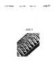
- FIG. 2shows such an end face. Such an end face is very impact-sensitive and can easily break out.
- the sharp-edged splintersthen lie on the surface of the usable plate and, in the case of hybrid production (production of a printed circuit (16) by printing on a metal paste), readily result in gaps in the printed image or even destruction of the printing screen, which has major production losses as a consequence.
- This end face forma hinderance to accurate and flawless further processing, must consequently be improved by grinding, in order to create right angles in all three spacial directions and reduce macrowaviness and microwaviness as well as roughness of the rupture surface and break-outs.
- FIG. 3shows an end face after grinding.
- rindingis understood to mean all processes of machining or material-removing working, including the alternatively possible liquid-jet cutting, which may also be used instead of laser severing.
- the safety distance (20) between printed image (16) and outer predetermined breaking point (12)can be reduced and consequently, with the same dimensions of the overall plate, the usable surface area of (19) can be increased.
- the plates produced in such a way for microelectronicstypically have an edge length of 5 ⁇ 5 cm to 20 ⁇ 20 cm, it being possible for an individually separated component (17) from such a plate to be only a few square millimeters in size.
- This processhas the disadvantage that the plates have to be clamped and reclamped four times for grinding the end faces and that, to compensate for deviations in dimensions and size which occur when breaking off the borders, an oversize of 0.5 mm to 0.7 mm is necessary for grinding.
- the plates obtained by the prior artare generally rectangular. A lack of care when breaking off the outer border and when grinding can in this case result in plates on which one edge is skewed (trapezoidal shape) or a plurality of edges are skewed (parallelogram-like shape). If then the inner predetermined breaking points (13) and, if appropriate, clearances (14) are to be made at a later time, the accuracy of the positioning deteriorates. For this case, a safety distance (20) between printed image (16) and outer predetermined breaking point (12) and between (16) and inner predetermined breaking points (13) which is about 0.3 mm on all sides must be maintained.
- the aim of the present inventionis to provide an inexpensive process which allows the production of plates of brittle material, in particular rectangular plates, with high accuracy which may also have inner predetermined breaking points (13), clearances (14), such as for example bores, of any design and/or printed images (16) created by metal pastes.
- a processhas now been found for producing a plate from a brittle material which can be individually separated by breaking to form one or more smaller platelets of predetermined dimensions.
- the processis one wherein laser scoring is used to produce in a single plate of large dimensions of a brittle material
- the border zoneis removed in the outer region at the distance d a from the two outer first predetermined breaking points and at the distance d b from the two outer second predetermined breaking points, so that the remaining plate, without border pieces, contains (a-1) ⁇ (b-1) platelet sections of the same size, which are bounded by in each case four predetermined breaking points. All the predetermined breaking points are to pass through the remaining plate, i.e. not end in it. Therefore, the remaining plate contains in its border zone 2 ⁇ (a+b) platelet sections, which have only 2 or 3 predetermined breaking points.
- Preferably ceramicis used as the brittle material of the relatively large single plate.
- the removal of the border zonemay be performed by laser scoring and breaking off, laser cutting or mechanical cutting (sawing, water-jet cutting or similar separating processes). If the border zone is removed by laser scoring and breaking off, the end faces of the usable plate are to be subsequently ground.
- an approximately rectangular relatively large plateis taken first of all and the first and the second predetermined breaking points are arranged in such a way that they run perpendicularly to each other, so that the plate remaining (after removing the border zone) is rectangular and, if appropriate, can be individually separated into a plurality of rectangular platelet sections of the same size.
- the process according to the inventionreadily succeeds in limiting the parallelism deviations of opposing end faces of the useful faces produced by separating and grinding to a maximum of 0.05%, preferably to a maximum of 0.03% of the useful-face edge length.
- the process according to the inventionis of particular value if it is desired to produce in the small platelet sections at a precise predetermined position at least one hole by laser drilling, at least one clearance by laser cutting and/or a printed electric circuit by screen printing.
- the grinding processcan be dispensed with, since the edges produced are smooth and free from damage.
- the clearances (14) and the inner predetermined breaking points (13)can be produced by a multi-head laser.
- the procedure adoptedis that the plate is laser-scored for removal of the border zone, maintaining during this outer laser scoring a distance which is slightly greater (about 0.1 to 0.2 mm) than the distance d a or d b , the border zone produced by laser scoring is broken off and the rupture edges of the plate produced during breaking off are ground down until the distance from the next predetermined breaking point is exactly d a or d b , respectively ("method 2").
- a plate or a plurality of plates next to one anotheris/are positioned on a laser table in a free, but ordered manner. Then, the outer predetermined breaking points (12) are lasered in the interior of the plate (18) and, if appropriate, inner predetermined breaking points (13) and also clearances and bores (14) are lasered in one go by one or more laser heads. After the breaking off of the border (11), the precise cutting or grinding of the end faces is performed. In this case, each individual plate has to be aligned for the grinding operation with reference to the inner contours (13) or the clearances (14) by electronic means, for example photodiodes or a camera and an x-y positioning table.
- the plateis positioned with reference to the contours of (12), (13) and (14) for grinding, it is ensured that both the angularity and the tolerance in terms of shape and position of the outer predetermined breaking point (12) and inner contours of (13) and (14) with respect to each other on each plate are very close to the working accuracy of the electronic measuring instrument.
- At least three narrow, rectangular clearancesare made by laser cutting at the outer predetermined breaking points produced by laser scoring, of which clearances at least two are arranged on the same side and at least one is arranged on a neighboring side.
- the clearancesof course it is possible to dispense with the preceding scoring.
- the narrow clearancestouch from the outside the outer predetermined breaking points produced by laser scoring, or the center axes of the clearances coincide with the predetermined breaking points.
- a multi-head laseris used to produce simultaneously the outer predetermined breaking point (12) of the plate by laser scoring and laser cutting of three stop faces (15) on two neighboring edges together with predetermined breaking points (13) and inner contours of (14).
- FIG. 4shows a blank substrate (18) with laser-scored outer predetermined breaking point (12), rupture border (11), laser-scored inner predetermined breaking points (13), laser-cut clearances (14) and three laser-cut edge sections (15).
- the sections (15)are well-defined and smooth and serve during grinding as stop points.
- a single plate prepared by this processcan be clamped exactly and reproducibly into a rotary grinding apparatus, the plate can be rotated and all four end faces can be ground exactly to size and angularity, without releasing the clamping.
- the clamping jaws (2) and (5)represent pressure contacts which firmly hold an individual plate or press together a plurality of plates on their surfaces as a stack.
- the axis of rotationpreferably runs through the center points of the rectangles of the plates, because then the effort for adjusting the distance of the grinding apparatus during operation is at its least.
- Either the grinding unit or the clamping mechanism (1, 2, 5) with the two clamping jaws which hold the stack of platesis preferably arranged linearly movably, in order that the effective surface of the grinding apparatus can slide past along the end faces of the stack of plates in a grinding manner.
- the auxiliary device (3)preferably contains stop locations, in particular of hard materials. This is advisable if the plates to be ground already have three cut-through edge sections (15). This development permits the exact alignment of the usable plate parallel to the machine table.
- the placing-in device (3)After clamping in, the placing-in device (3) is removed and the first end face of a plate is ground. After completion of this end face, the plate or the stack of plates is swivelled through 90° in the clamped-in state with the aid of the precision dividing device (1) and the abutment (6) and is arrested in this position for the grinding of the second end face. The same procedure is followed correspondingly with the remaining end faces.
- the platelies so accurately and angularly in the apparatus that it is possible to work with a minimal grinding feed of only 0.1-0.2 mm and consequently inexpensively. All the disadvantages of an inferior end face are avoided.
- the apparatusallows not only a single plate but also a plurality of plates to be clamped in and ground simultaneously.
- the second developmentlikewise allows the plates to be worked inexpensively and in one clamping operation on a multi-head laser. When grinding the end faces, however, each plate must be placed on individually, measured, aligned and then ground.
- the third methodcombines all the abovementioned advantages and allows the avoidance of disadvantages.
- the platescan be lasered in one clamping operation, utilizing the full laser capacity of multi-head lasers.
- the time-consuming and cost-intensive cutting through of the outer contouris restricted to three small smooth edge sections, i.e. only to a fraction of the periphery.
- the process according to the inventioncan be used for improving substrates of all types, whether metal, plastic or ceramic and also for composite materials, such as for example circuit boards or metallized ceramic, and ceramic laminates (multilayers and monoliths of small height, for example chip housings, piezo elements, sensors and heat exchangers). Plates are understood here to mean both boards for microelectronics and as a base for other intended uses in the general sense and also as laminates of small height.
Landscapes
- Engineering & Computer Science (AREA)
- Mechanical Engineering (AREA)
- Chemical & Material Sciences (AREA)
- Ceramic Engineering (AREA)
- Inorganic Chemistry (AREA)
- Processing Of Stones Or Stones Resemblance Materials (AREA)
- Laser Beam Processing (AREA)
Abstract
Description
______________________________________Item 1 represents a precision dividing device having a clamping jaw (2) which is situated in a plane perpendicular to the axis (9), is rotatable about this axis and can be arrested by means of the screw (10) at a predetermined rotational angle;Item 3 represents a placing-in device having two receiving faces, situated perpendicularly to each other, for the positionally and angularly accurate placing in of at least one plate on which the border (11) has been removed. This placing-in device lies loosely on the baseplate (8); Item 4 represents space for at least one plate which is to be ground; Item 5 represents a clamping jaw which can be moved in the direction of the axis (9), can be rotated about the latter, is mounted rotatably in the abutment (6) and can be moved by means of a spindle (7) in the axial direction;Item 8 represents the baseplate of the apparatus, which can be arrested fixedly on a table by means of clamping claws or a magnetic clamping table. ______________________________________
______________________________________Prior Method 1 2 3 Art ______________________________________ Parallelism of inner to outer contour (values in %): Mean value 0.027 0.041 0.027 0.066 Spread 0.0203 0.0262 0.0185 0.0443 Minimum value 0.002 0.000 0.001 0.011 Maximum value 0.075 0.074 0.067 0.168 Angular deviation (values in %): Mean value 0.012 0.011 0.008 0.06 Spread 0.0080 0.0071 0.0067 0.027 Maximum value 0.02 0.02 0.02 0.12 ______________________________________
Claims (13)
Applications Claiming Priority (4)
| Application Number | Priority Date | Filing Date | Title |
|---|---|---|---|
| DE4306296 | 1993-03-02 | ||
| DE4306296.2 | 1993-03-02 | ||
| DE4344383.4 | 1993-12-24 | ||
| DE4344383 | 1993-12-24 |
Publications (1)
| Publication Number | Publication Date |
|---|---|
| US5626777Atrue US5626777A (en) | 1997-05-06 |
Family
ID=25923538
Family Applications (1)
| Application Number | Title | Priority Date | Filing Date |
|---|---|---|---|
| US08/203,417Expired - LifetimeUS5626777A (en) | 1993-03-02 | 1994-03-01 | Process for producing dividable plates of brittle material with high accuracy and apparatus for receiving and precision-grinding the end faces of a plate |
Country Status (4)
| Country | Link |
|---|---|
| US (1) | US5626777A (en) |
| EP (1) | EP0613765B1 (en) |
| DE (1) | DE59408996D1 (en) |
| DK (1) | DK0613765T3 (en) |
Cited By (14)
| Publication number | Priority date | Publication date | Assignee | Title |
|---|---|---|---|---|
| US5882438A (en)* | 1995-12-19 | 1999-03-16 | Bayerische Motoren Werke Aktiengesellschaft | Method for the formation of a frangible zone for the fracture separation of a machine part, in particular, a connecting rod for internal combustion engines |
| WO2001085387A1 (en)* | 2000-05-11 | 2001-11-15 | Ptg Precision Technology Center Limited Llc | System for cutting brittle materials |
| WO2001054851A3 (en)* | 2000-01-31 | 2002-03-14 | Picojet Inc | Microfluid device and ultrasonic bonding process |
| US20030089206A1 (en)* | 2001-11-09 | 2003-05-15 | Tsuyoshi Ueno | Method of aligning a workpiece in a cutting machine |
| US6580054B1 (en) | 2002-06-10 | 2003-06-17 | New Wave Research | Scribing sapphire substrates with a solid state UV laser |
| US20040029362A1 (en)* | 2002-06-10 | 2004-02-12 | New Wave Research | Method and apparatus for cutting devices from substrates |
| US20040087112A1 (en)* | 2002-11-05 | 2004-05-06 | New Wave Research | Method and apparatus for cutting devices from conductive substrates secured during cutting by vacuum pressure |
| US20040228004A1 (en)* | 2003-02-19 | 2004-11-18 | Sercel Patrick J. | System and method for cutting using a variable astigmatic focal beam spot |
| WO2004113041A3 (en)* | 2003-06-16 | 2005-02-24 | Curamik Electronics Gmbh | Method for producing a ceramic/metal substrate |
| US20060050109A1 (en)* | 2000-01-31 | 2006-03-09 | Le Hue P | Low bonding temperature and pressure ultrasonic bonding process for making a microfluid device |
| US20090293537A1 (en)* | 2008-05-27 | 2009-12-03 | Ameringer Greg E | NGL Extraction From Natural Gas |
| US20110132885A1 (en)* | 2009-12-07 | 2011-06-09 | J.P. Sercel Associates, Inc. | Laser machining and scribing systems and methods |
| US20130256286A1 (en)* | 2009-12-07 | 2013-10-03 | Ipg Microsystems Llc | Laser processing using an astigmatic elongated beam spot and using ultrashort pulses and/or longer wavelengths |
| BE1024350B1 (en)* | 2016-06-29 | 2018-02-05 | C-Mac Electromag Bvba | Automated system for the singulation of circuits from DBC substrates, and method thereof |
Families Citing this family (3)
| Publication number | Priority date | Publication date | Assignee | Title |
|---|---|---|---|---|
| TW353202B (en)* | 1997-02-28 | 1999-02-21 | Hewlett Packard Co | Scribe and break of hard-to-scribe materials |
| DE19729922C1 (en)* | 1997-07-04 | 1999-01-21 | Fraunhofer Ges Forschung | Method for producing metal-coated diamond thermal conductors |
| DE10017691A1 (en)* | 2000-04-08 | 2001-10-11 | Bayerische Motoren Werke Ag | Method for forming a line of weakness in a break-separable component, in particular with a bearing arrangement |
Citations (9)
| Publication number | Priority date | Publication date | Assignee | Title |
|---|---|---|---|---|
| US3556366A (en)* | 1969-05-01 | 1971-01-19 | Teletype Corp | Methods of severing materials employing a thermal shock |
| US3687345A (en)* | 1970-11-23 | 1972-08-29 | Signetics Corp | Method and apparatus for aligning and breaking wafers |
| US3814895A (en)* | 1971-12-27 | 1974-06-04 | Electroglas Inc | Laser scriber control system |
| US4224101A (en)* | 1976-09-03 | 1980-09-23 | U.S. Philips Corporation | Method of manufacturing semiconductor devices using laser beam cutting |
| US4352446A (en)* | 1978-09-11 | 1982-10-05 | Mti Systems Corporation | Substrate separating machine and method |
| JPH0218903A (en)* | 1988-07-07 | 1990-01-23 | Rohm Co Ltd | Ceramic substrate for chip component |
| US4918284A (en)* | 1988-10-14 | 1990-04-17 | Teradyne Laser Systems, Inc. | Calibrating laser trimming apparatus |
| US5063280A (en)* | 1989-07-24 | 1991-11-05 | Canon Kabushiki Kaisha | Method and apparatus for forming holes into printed circuit board |
| US5214261A (en)* | 1990-09-10 | 1993-05-25 | Rockwell International Corporation | Method and apparatus for dicing semiconductor substrates using an excimer laser beam |
Family Cites Families (4)
| Publication number | Priority date | Publication date | Assignee | Title |
|---|---|---|---|---|
| US2978804A (en)* | 1958-08-13 | 1961-04-11 | Sylvania Electric Prod | Method of classifying non-magnetic elements |
| NL299821A (en)* | 1962-10-31 | 1900-01-01 | ||
| DE3404128C1 (en)* | 1984-02-07 | 1985-09-05 | Maschinen- und Stahlbau Julius Lippert GmbH & Co, 8487 Pressath | Numerically controlled machine for processing the edge of a ceramic object |
| US4629378A (en)* | 1984-08-27 | 1986-12-16 | Parsons John T | Meltable matrix chucking machining center and process using |
- 1994
- 1994-02-24EPEP94102776Apatent/EP0613765B1/ennot_activeExpired - Lifetime
- 1994-02-24DEDE59408996Tpatent/DE59408996D1/ennot_activeExpired - Lifetime
- 1994-02-24DKDK94102776Tpatent/DK0613765T3/enactive
- 1994-03-01USUS08/203,417patent/US5626777A/ennot_activeExpired - Lifetime
Patent Citations (9)
| Publication number | Priority date | Publication date | Assignee | Title |
|---|---|---|---|---|
| US3556366A (en)* | 1969-05-01 | 1971-01-19 | Teletype Corp | Methods of severing materials employing a thermal shock |
| US3687345A (en)* | 1970-11-23 | 1972-08-29 | Signetics Corp | Method and apparatus for aligning and breaking wafers |
| US3814895A (en)* | 1971-12-27 | 1974-06-04 | Electroglas Inc | Laser scriber control system |
| US4224101A (en)* | 1976-09-03 | 1980-09-23 | U.S. Philips Corporation | Method of manufacturing semiconductor devices using laser beam cutting |
| US4352446A (en)* | 1978-09-11 | 1982-10-05 | Mti Systems Corporation | Substrate separating machine and method |
| JPH0218903A (en)* | 1988-07-07 | 1990-01-23 | Rohm Co Ltd | Ceramic substrate for chip component |
| US4918284A (en)* | 1988-10-14 | 1990-04-17 | Teradyne Laser Systems, Inc. | Calibrating laser trimming apparatus |
| US5063280A (en)* | 1989-07-24 | 1991-11-05 | Canon Kabushiki Kaisha | Method and apparatus for forming holes into printed circuit board |
| US5214261A (en)* | 1990-09-10 | 1993-05-25 | Rockwell International Corporation | Method and apparatus for dicing semiconductor substrates using an excimer laser beam |
Cited By (39)
| Publication number | Priority date | Publication date | Assignee | Title |
|---|---|---|---|---|
| US5882438A (en)* | 1995-12-19 | 1999-03-16 | Bayerische Motoren Werke Aktiengesellschaft | Method for the formation of a frangible zone for the fracture separation of a machine part, in particular, a connecting rod for internal combustion engines |
| US6783213B2 (en) | 2000-01-31 | 2004-08-31 | Picojet, Inc. | Microfluid device and ultrasonic bonding process |
| WO2001054851A3 (en)* | 2000-01-31 | 2002-03-14 | Picojet Inc | Microfluid device and ultrasonic bonding process |
| US6464324B1 (en) | 2000-01-31 | 2002-10-15 | Picojet, Inc. | Microfluid device and ultrasonic bonding process |
| US6530653B2 (en) | 2000-01-31 | 2003-03-11 | Picojet, Inc. | Ultrasonic bonding of ink-jet print head components |
| US20060050109A1 (en)* | 2000-01-31 | 2006-03-09 | Le Hue P | Low bonding temperature and pressure ultrasonic bonding process for making a microfluid device |
| US6928731B2 (en) | 2000-01-31 | 2005-08-16 | Picojet, Inc. | Ultrasonic bonding process for making a microfluid device |
| US20040237304A1 (en)* | 2000-01-31 | 2004-12-02 | Picojet, Inc. | Ultrasonic bonding process for making a microfluid device |
| WO2001085387A1 (en)* | 2000-05-11 | 2001-11-15 | Ptg Precision Technology Center Limited Llc | System for cutting brittle materials |
| US20030089206A1 (en)* | 2001-11-09 | 2003-05-15 | Tsuyoshi Ueno | Method of aligning a workpiece in a cutting machine |
| US20040029362A1 (en)* | 2002-06-10 | 2004-02-12 | New Wave Research | Method and apparatus for cutting devices from substrates |
| US6580054B1 (en) | 2002-06-10 | 2003-06-17 | New Wave Research | Scribing sapphire substrates with a solid state UV laser |
| US8822882B2 (en) | 2002-06-10 | 2014-09-02 | New Wave Research | Scribing sapphire substrates with a solid state UV laser with edge detection |
| US7169688B2 (en) | 2002-06-10 | 2007-01-30 | New Wave Research, Inc. | Method and apparatus for cutting devices from substrates |
| US20030226830A1 (en)* | 2002-06-10 | 2003-12-11 | New Wave Research | Scribing sapphire substrates with a solid state UV laser |
| US7112518B2 (en) | 2002-06-10 | 2006-09-26 | New Wave Research | Method and apparatus for cutting devices from substrates |
| US20050095819A1 (en)* | 2002-06-10 | 2005-05-05 | New Wave Research | Method and apparatus for cutting devices from substrates |
| US20050153525A1 (en)* | 2002-06-10 | 2005-07-14 | New Wave Research | Method and apparatus for cutting devices from substrates |
| US20030226832A1 (en)* | 2002-06-10 | 2003-12-11 | New Wave Research | Scribing sapphire substrates with a solid state UV laser |
| US20050215078A1 (en)* | 2002-06-10 | 2005-09-29 | New Wave Research | Scribing sapphire substrates with a solid state UV laser |
| US6960813B2 (en) | 2002-06-10 | 2005-11-01 | New Wave Research | Method and apparatus for cutting devices from substrates |
| US6960739B2 (en) | 2002-06-10 | 2005-11-01 | New Wave Research | Scribing sapphire substrates with a solid state UV laser |
| US20050279740A1 (en)* | 2002-06-10 | 2005-12-22 | New Wave Research | Scribing sapphire substrates with a solid state UV laser with edge detection |
| US20060027886A1 (en)* | 2002-06-10 | 2006-02-09 | New Wave Research, Inc | Apparatus for cutting devices from conductive substrates secured during cutting by vacuum pressure |
| US7052976B2 (en) | 2002-11-05 | 2006-05-30 | New Wave Research | Method and apparatus for cutting devices from conductive substrates secured during cutting by vacuum pressure |
| US20040087112A1 (en)* | 2002-11-05 | 2004-05-06 | New Wave Research | Method and apparatus for cutting devices from conductive substrates secured during cutting by vacuum pressure |
| US6806544B2 (en) | 2002-11-05 | 2004-10-19 | New Wave Research | Method and apparatus for cutting devices from conductive substrates secured during cutting by vacuum pressure |
| US8502112B2 (en) | 2003-02-19 | 2013-08-06 | Ipg Microsystems Llc | System and method for cutting using a variable astigmatic focal beam spot |
| US20040228004A1 (en)* | 2003-02-19 | 2004-11-18 | Sercel Patrick J. | System and method for cutting using a variable astigmatic focal beam spot |
| US7388172B2 (en) | 2003-02-19 | 2008-06-17 | J.P. Sercel Associates, Inc. | System and method for cutting using a variable astigmatic focal beam spot |
| US20080242056A1 (en)* | 2003-02-19 | 2008-10-02 | J.P. Sercel Associates, Inc. | System and method for cutting using a variable astigmatic focal beam spot |
| US7709768B2 (en) | 2003-02-19 | 2010-05-04 | Jp Sercel Associates Inc. | System and method for cutting using a variable astigmatic focal beam spot |
| US20100301027A1 (en)* | 2003-02-19 | 2010-12-02 | J. P. Sercel Associates Inc. | System and method for cutting using a variable astigmatic focal beam spot |
| US20060183298A1 (en)* | 2003-06-16 | 2006-08-17 | Jurgen Schulz-Harder | Method for manufacturing a ceramic/metal substrate |
| WO2004113041A3 (en)* | 2003-06-16 | 2005-02-24 | Curamik Electronics Gmbh | Method for producing a ceramic/metal substrate |
| US20090293537A1 (en)* | 2008-05-27 | 2009-12-03 | Ameringer Greg E | NGL Extraction From Natural Gas |
| US20130256286A1 (en)* | 2009-12-07 | 2013-10-03 | Ipg Microsystems Llc | Laser processing using an astigmatic elongated beam spot and using ultrashort pulses and/or longer wavelengths |
| US20110132885A1 (en)* | 2009-12-07 | 2011-06-09 | J.P. Sercel Associates, Inc. | Laser machining and scribing systems and methods |
| BE1024350B1 (en)* | 2016-06-29 | 2018-02-05 | C-Mac Electromag Bvba | Automated system for the singulation of circuits from DBC substrates, and method thereof |
Also Published As
| Publication number | Publication date |
|---|---|
| EP0613765A1 (en) | 1994-09-07 |
| DK0613765T3 (en) | 2000-04-03 |
| DE59408996D1 (en) | 2000-01-20 |
| EP0613765B1 (en) | 1999-12-15 |
Similar Documents
| Publication | Publication Date | Title |
|---|---|---|
| US5626777A (en) | Process for producing dividable plates of brittle material with high accuracy and apparatus for receiving and precision-grinding the end faces of a plate | |
| TWI461377B (en) | Glass cutting machine and cutting line processing method | |
| JP5139852B2 (en) | Scribing apparatus and scribing method | |
| EP1475357B1 (en) | Fragile material substrate parting system | |
| CN101219519B (en) | Method and device for machining a workpiece with a cutting tool | |
| JP2004111946A (en) | Laser dicing equipment and dicing method | |
| EP1710095A1 (en) | Method for manufacturing a printing screen for serigraphy | |
| JP4359413B2 (en) | Mirror surface processing method, chamfering method and mirror surface processing apparatus, and peripheral finishing method of laminated film | |
| EP1800797A1 (en) | Polishing apparatus and polishing method | |
| JP2004209638A (en) | Tooling device | |
| JP2003089538A (en) | Breaking device and breaking method for brittle material substrate | |
| JP2012190932A (en) | Processing device | |
| WO2021085490A1 (en) | Ceramic substrate and method for producing same, composite substrate and method for producing same, and circuit board and method for producing same | |
| JP6792794B2 (en) | Manufacturing equipment for silicon nitride ceramic assembly substrate and manufacturing method for silicon nitride ceramic assembly substrate | |
| JP4645844B2 (en) | Multi-type wire saw and processing method using wire saw | |
| JPH10314972A (en) | Laser beam machine | |
| JPH0535646B2 (en) | ||
| EP0333995A2 (en) | An apparatus of chamfering planar plate | |
| US20050098549A1 (en) | Laser beam machining apparatus | |
| JP2000012409A (en) | Method and device for producing ceramic electronic components | |
| JP2005014126A (en) | Pitch variable processing method using multi-wire saw and multi-wire saw | |
| JP5666876B2 (en) | Method for dividing multilayer ceramic capacitor substrate | |
| JP2002050820A (en) | Method and device for cleaving semiconductor device | |
| JPH05330837A (en) | Press type cutting method for glass substrate | |
| JPH09285923A (en) | Polyhedral processing machine and processing method thereof |
Legal Events
| Date | Code | Title | Description |
|---|---|---|---|
| AS | Assignment | Owner name:HOECHST CERAMTEC AKTIENGESELLSCHAFT, GERMANY Free format text:ASSIGNMENT OF ASSIGNORS INTEREST;ASSIGNORS:HUEGL, KURT;LENEIS, ROLAND;REEL/FRAME:006897/0236 Effective date:19940211 | |
| AS | Assignment | Owner name:HOECHST AKTIENGESELLSCHAFT, GERMANY Free format text:ASSIGNMENT OF ASSIGNOR'S INTEREST (RECORD TO CORRECT ASSIGNEE'S NAME PREVIOUSLY RECORDED AT REEL 6897 FRAME 236).;ASSIGNORS:HUEGL, KURT;LENEIS, ROLAND;REEL/FRAME:008033/0760 Effective date:19940211 | |
| AS | Assignment | Owner name:HOECHST CERAMTEC AG, GERMANY Free format text:ASSIGNMENT OF ASSIGNORS INTEREST;ASSIGNOR:HOECHST AKTIENGESELLSCHAFT;REEL/FRAME:008083/0285 Effective date:19960726 | |
| STCF | Information on status: patent grant | Free format text:PATENTED CASE | |
| FEPP | Fee payment procedure | Free format text:PAYOR NUMBER ASSIGNED (ORIGINAL EVENT CODE: ASPN); ENTITY STATUS OF PATENT OWNER: LARGE ENTITY | |
| FPAY | Fee payment | Year of fee payment:4 | |
| FPAY | Fee payment | Year of fee payment:8 | |
| FPAY | Fee payment | Year of fee payment:12 | |
| AS | Assignment | Owner name:DEUTSCHE BANK AG NEW YORK BRANCH, AS COLLATERAL AGENT, NEW YORK Free format text:SECURITY AGREEMENT;ASSIGNOR:CERAMTEC GMBH;REEL/FRAME:031217/0929 Effective date:20130901 Owner name:DEUTSCHE BANK AG NEW YORK BRANCH, AS COLLATERAL AG Free format text:SECURITY AGREEMENT;ASSIGNOR:CERAMTEC GMBH;REEL/FRAME:031217/0929 Effective date:20130901 | |
| AS | Assignment | Owner name:CERAMTEC AG INNOVATIVE CERAMIC ENGINEERING, GERMAN Free format text:CHANGE OF NAME;ASSIGNOR:HOECHST CERAMTEC AG;REEL/FRAME:031718/0607 Effective date:19960923 | |
| AS | Assignment | Owner name:CERAMTECH GMBH, GERMANY Free format text:CHANGE OF NAME;ASSIGNOR:CERAMTEC AG;REEL/FRAME:031730/0672 Effective date:20100922 Owner name:CERAMTEC AG, GERMANY Free format text:MERGER;ASSIGNOR:CERAMTEC AG INNOVATIVE CERAMIC ENGINEERING;REEL/FRAME:031730/0290 Effective date:20071122 | |
| AS | Assignment | Owner name:CERAMTEC GMBH, GERMANY Free format text:RELEASE BY SECURED PARTY;ASSIGNOR:DEUTSCHE BANK AG NEW YORK BRANCH;REEL/FRAME:045597/0537 Effective date:20180302 |