US5626542A - Folding rider exerciser - Google Patents
Folding rider exerciserDownload PDFInfo
- Publication number
- US5626542A US5626542AUS08/594,940US59494096AUS5626542AUS 5626542 AUS5626542 AUS 5626542AUS 59494096 AUS59494096 AUS 59494096AUS 5626542 AUS5626542 AUS 5626542A
- Authority
- US
- United States
- Prior art keywords
- receiver
- user
- riding
- base
- pull
- Prior art date
- Legal status (The legal status is an assumption and is not a legal conclusion. Google has not performed a legal analysis and makes no representation as to the accuracy of the status listed.)
- Expired - Lifetime
Links
Images


Classifications
- A—HUMAN NECESSITIES
- A63—SPORTS; GAMES; AMUSEMENTS
- A63B—APPARATUS FOR PHYSICAL TRAINING, GYMNASTICS, SWIMMING, CLIMBING, OR FENCING; BALL GAMES; TRAINING EQUIPMENT
- A63B23/00—Exercising apparatus specially adapted for particular parts of the body
- A63B23/035—Exercising apparatus specially adapted for particular parts of the body for limbs, i.e. upper or lower limbs, e.g. simultaneously
- A63B23/12—Exercising apparatus specially adapted for particular parts of the body for limbs, i.e. upper or lower limbs, e.g. simultaneously for upper limbs or related muscles, e.g. chest, upper back or shoulder muscles
- A—HUMAN NECESSITIES
- A63—SPORTS; GAMES; AMUSEMENTS
- A63B—APPARATUS FOR PHYSICAL TRAINING, GYMNASTICS, SWIMMING, CLIMBING, OR FENCING; BALL GAMES; TRAINING EQUIPMENT
- A63B21/00—Exercising apparatus for developing or strengthening the muscles or joints of the body by working against a counterforce, with or without measuring devices
- A63B21/06—User-manipulated weights
- A63B21/068—User-manipulated weights using user's body weight
- A—HUMAN NECESSITIES
- A63—SPORTS; GAMES; AMUSEMENTS
- A63B—APPARATUS FOR PHYSICAL TRAINING, GYMNASTICS, SWIMMING, CLIMBING, OR FENCING; BALL GAMES; TRAINING EQUIPMENT
- A63B21/00—Exercising apparatus for developing or strengthening the muscles or joints of the body by working against a counterforce, with or without measuring devices
- A63B21/40—Interfaces with the user related to strength training; Details thereof
- A63B21/4027—Specific exercise interfaces
- A63B21/4033—Handles, pedals, bars or platforms
- A63B21/4035—Handles, pedals, bars or platforms for operation by hand
- A—HUMAN NECESSITIES
- A63—SPORTS; GAMES; AMUSEMENTS
- A63B—APPARATUS FOR PHYSICAL TRAINING, GYMNASTICS, SWIMMING, CLIMBING, OR FENCING; BALL GAMES; TRAINING EQUIPMENT
- A63B21/00—Exercising apparatus for developing or strengthening the muscles or joints of the body by working against a counterforce, with or without measuring devices
- A63B21/40—Interfaces with the user related to strength training; Details thereof
- A63B21/4041—Interfaces with the user related to strength training; Details thereof characterised by the movements of the interface
- A63B21/4047—Pivoting movement
- A—HUMAN NECESSITIES
- A63—SPORTS; GAMES; AMUSEMENTS
- A63B—APPARATUS FOR PHYSICAL TRAINING, GYMNASTICS, SWIMMING, CLIMBING, OR FENCING; BALL GAMES; TRAINING EQUIPMENT
- A63B23/00—Exercising apparatus specially adapted for particular parts of the body
- A63B23/035—Exercising apparatus specially adapted for particular parts of the body for limbs, i.e. upper or lower limbs, e.g. simultaneously
- A63B23/12—Exercising apparatus specially adapted for particular parts of the body for limbs, i.e. upper or lower limbs, e.g. simultaneously for upper limbs or related muscles, e.g. chest, upper back or shoulder muscles
- A63B23/1245—Primarily by articulating the shoulder joint
- A63B23/1263—Rotation about an axis passing through both shoulders, e.g. cross-country skiing-type arm movements
- A—HUMAN NECESSITIES
- A63—SPORTS; GAMES; AMUSEMENTS
- A63B—APPARATUS FOR PHYSICAL TRAINING, GYMNASTICS, SWIMMING, CLIMBING, OR FENCING; BALL GAMES; TRAINING EQUIPMENT
- A63B2210/00—Space saving
- A63B2210/50—Size reducing arrangements for stowing or transport
- A—HUMAN NECESSITIES
- A63—SPORTS; GAMES; AMUSEMENTS
- A63B—APPARATUS FOR PHYSICAL TRAINING, GYMNASTICS, SWIMMING, CLIMBING, OR FENCING; BALL GAMES; TRAINING EQUIPMENT
- A63B23/00—Exercising apparatus specially adapted for particular parts of the body
- A63B23/035—Exercising apparatus specially adapted for particular parts of the body for limbs, i.e. upper or lower limbs, e.g. simultaneously
- A63B23/03575—Apparatus used for exercising upper and lower limbs simultaneously
- A—HUMAN NECESSITIES
- A63—SPORTS; GAMES; AMUSEMENTS
- A63B—APPARATUS FOR PHYSICAL TRAINING, GYMNASTICS, SWIMMING, CLIMBING, OR FENCING; BALL GAMES; TRAINING EQUIPMENT
- A63B23/00—Exercising apparatus specially adapted for particular parts of the body
- A63B23/035—Exercising apparatus specially adapted for particular parts of the body for limbs, i.e. upper or lower limbs, e.g. simultaneously
- A63B23/12—Exercising apparatus specially adapted for particular parts of the body for limbs, i.e. upper or lower limbs, e.g. simultaneously for upper limbs or related muscles, e.g. chest, upper back or shoulder muscles
- A63B23/1209—Involving a bending of elbow and shoulder joints simultaneously
Definitions
- This applicationrelates to riding exercise machines and more particularly to a riding exercise machine that may be reconfigured between a use configuration and a storage configuration.
- Exercise machinesin which the user mounts the machine and sits upon a moving seat interconnected to a handle which is pulled to raise the seat against the weight of the user may be regarded as riding exercise machines.
- U.S. Pat. No. 4,300,760(Bobroff) illustrates one form of exercise machine in which the user mounts the machine and operates a lever mechanism with the arms and the feet against a resistance which is the user's weight positioned upon the seat.
- HEALTHRIDERTMCommercial riding exercise machines
- the HEALTHRIDER machinehas a frame with a rotatable or movable lever interconnected to a seat.
- the leveris operated by the user's hands and feet against the resistance of the user reclining on a seat in a fashion similar to that illustrated in the Bobroff patent.
- the CARDIOGLIDE machinesold by ICON Health & Fitness, Inc. of Logan, Utah also has a frame with a seat interconnected with a lever. It also has a resistance mechanism interconnected to resist movement of the lever and seat.
- 3,446,503(Lawton) illustrates another form of riding machine in which a handle is interconnected with a seat.
- U.S. Pat. No. 5,299,997(Chen) also shows a riding-type exercise machine in which the user's weight is used to resist movement of feet and hands.
- Other patents disclosing similar or related machinesinclude U.S. Pat. No. 5,306,218 (Chen), U.S. Pat. No. 5,366,428 (Liao), U.S. Pat. No. 5,370,594 (Grinblat) and U.S. Pat. No. 5,356,357 (Wang, et al.).
- a riding exercise machineis reconfigurable between a use configuration and a storage configuration.
- the machinehas a base with a guide surface associated therewith.
- Feet meansare attached to the opposite ends of the base to support the base on a support surface.
- User support meansis rotatably attached to the base to be movable between a use configuration and storage configuration.
- the user support meanssupports a riding user thereon when in the user configuration. In the user configuration, the user support means is movable and preferably rotatable between a first position and a second position spaced from the first position.
- Guide meansare rotatably attached to the user support means to extend away therefrom.
- the guide meansare in contact with the guide surface and are movable between a use configuration and a storage configuration. In the user configuration, the guide means is movable between a first position when the user support means is in its first position and a second position when the user support means is in its second position.
- Forward support structurehaving a lower end and an upper end is also provided.
- the lower end of the forward support structureis removably attached to the base in the use configuration. It is detached from the base and reoriented toward alignment with the base in the storage configuration.
- a pull receiveris preferably rotatably attached to the forward support structure to be movable between a first position and a second position spaced from the first position.
- Handle structurehaving a handle portion for grasping and movement by a user riding on the user support means is also provided.
- the handle structureis mechanically associated with the pull receiver to be movable with the receiver from a use configuration to a storage configuration.
- the handle structureWhen in the use configuration the handle structure is pullable from a first position when the receiver is in its first position to a second position when the pull receiver is in its second position.
- the handle structure in its second positionis spaced toward the user support means from the handle structure first position.
- Attaching meansare optionally associated with one of the handle structure and the pull receiver for removably securing the handle structure to the pull receiver.
- Synchronizing meansare also provide to extend between and to be rotatably connected to the pull receiver and to the guide means.
- the synchronizing meansconnects the pull receiver to the guide means so that upon movement of the pull receiver and the handle structure between their respective first positions and second positions, the guide means and in turn the user support means move from their respective first positions to their respective second positions.
- the synchronizing meansis removably connected to be removed in the storage configuration and to be connected in the user configuration.
- the forward support structureis removably attached to the base by a support connector.
- the support connectorpreferably includes apertures formed in the base and the forward support structure to be in registration to receive a pin therethrough.
- the pinis operable by a user to disassociate the forward support structure from the base.
- the riding exercise machinealso includes a push receiver rotatably adapted to the base to receive the handle structure in the use configuration for pushing movement by a riding user on the user support means.
- the push receiveris movable from a first position in which the user support means is in its first position, to a second position in which the user support means is in its second position and the handle structure is spaced further away from the user on the user support means than when the handle structure is in its first position.
- the synchronizing meansincludes first connecting means having a first end and a second end.
- the first end of the connecting meansis rotatably connected to the pull receiver.
- the second end of the first connecting meansis rotatably connected to the push receiver.
- the first connecting meansconnects the pull receiver to the push receiver so that upon movement of the user support means from its first position to its second position, the pull receiver moves from its first position to its second position.
- the preferred arrangementalso includes second connecting means having a first end and a second end.
- the first endis rotatably connected to the push receiver.
- the second endis rotatably connected to the guide means.
- the second connecting meansis connected to the push receiver and to the guide means so that upon movement of the push receiver, as well as the pull receiver, between their first positions and their second positions, the guide means moves from its first position to its second position. At the same time, the user support means moves from its first position to its second position.
- the user support meansincludes a support member with a seat positioned proximate its distal end.
- the pull receiver and the push receiverare each receptacles sized to slidably and snugly receiver the handle structure therein.
- Locking meansmay be provided to lock the handle structure in the pull receiver and in the push receiver.
- the first connecting means and the second connecting meansare each rotatably attached to the push receiver to rotate about a common axis.
- the handle structurealso has a lower portion to which foot means are attached to support the feet of a riding user.
- the baseis a box beam having an upper surface that functions as the guide surface.
- the guide meansdesirably includes a guide member rotatably attached to the support member.
- the guide memberis a wheel which is rotatably attached proximate the distal end of the guide member. The wheel contacts the guide surface to move thereon and therealong.
- the locking meansis configured to lock the handle structure at a plurality of spaced apart locations along the length of the handle structure.
- the forward support structureis a pair of spaced apart members in substantial alignment.
- the pull receiveris rotatably attached proximate the upper end of the forward support structure.
- the synchronizing structuremay be a single strap extending between the pull receiver and the guide means.
- the single strapmay be removably connected either to the pull receiver or the guide means so the riding machine may be reconfigured from a use configuration to a storage configuration.
- FIG. 1is a simplified perspective view of a riding exerciser of the invention
- FIG. 2is a simplified side-view of the riding exerciser of FIG. 1 in a use configuration
- FIG. 3is a simplified side-view of the riding exerciser of FIG. 2 in a storage configuration
- FIG. 4is a perspective, simplified broken view of an alternate riding exerciser of the invention.
- FIG. 5is a simplified side-view of the riding exerciser of FIG. 4 in a use configuration
- FIG. 6is a simplified side-view of the riding exerciser of FIG. 5 in the storage configuration
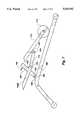
- FIG. 7are potions of the riding exerciser of FIG. 5 in a simplified side-view.
- FIG. 8is a simplified partial perspective view of a connecting structure for use with the riding exercise machines of FIGS. 1 and 4.
- the riding exerciser 10 of FIG. 1has a base 12 with feet means associated therewith to support the riding exerciser 10 on a support surface.
- the feet means as here illustratedinclude a forward foot 14 which is fastened to the base 12 by welding, bolts or other acceptable means.
- the forward foot 14is a cylindrically-shaped tube with a pair of end caps 16 and 18 secured to its outer ends.
- the end caps 16 and 18may be made out of a soft or rubber-like or plastic-like material to provide for frictional contact with the support surface without causing any marring or scratching.
- the feet meansalso includes a rear foot 20 attached to the base 12.
- the rear caps 22 and 24which are similarly made of a rubber-like or plastic-like material for frictional contact with the support surface while minimizing the risk of scratching or marring of the support surface.
- User support means 26is rotatably attached to the base 12.
- the user support means 26includes a support member 28 having a seat or cushion 30 affixed proximate the distal end 32 of the support member 28.
- the support member 28is comprised of a right tube 28A and a left tube 28B spaced apart to receive other components thereinbetween as discussed hereinafter.
- the support member 28is rotatably attached by a pin or axle 34 to the base 12.
- the pin or axle 34passes through apertures formed in the right tube 28A, the left tube 28B and the base 12 to provide for rotation of the user support means 26 from the first position 36 to a second position 38 (shown in dotted line) in FIG. 1. That is, the user support means 26 rotates about the axle on pin 34 between a first position and a second position spaced from the first position during the performance of exercise.
- the weight of the user residing on the seat 30resists movement of the user support means 26 from the first position 36 toward the second position 38.
- the riding machine of FIG. 1also includes guide means 39 rotatably connected to the user support means 26 to extend away therefrom. More specifically, guide means 39 includes a guide member 40 which is rotatably connected to the user support means 26 and more particularly the support member 28. A pin or axle 42 extends through appropriate apertures formed in the right support tube 28A and left support tube 28B. A bushing or spacer 44 is interpositioned between the right tube 28A and the left tube 28B with the axle 42 passing therethrough. The guide support 40 is fixedly attached to the bushing 44 such as by welding and in turn is rotatable about the axle 42.
- the guide surface 50is here shown to be the upper surface of the box beam or rectangular tube which constitutes the base 12.
- the wheel 48moves along the guide surface 50 as the user support means moves between its first position 41 as shown in solid and its second position 43.
- the guide means 39is in its first position 41 when the user support means 26 is in its first position 36; and the guide means 39 is in its second position 43 when the user support means is in its second position 38.
- a forward support structure 52is attached to the base 12 forward of the user support means 26.
- the forward support structure 52has a lower end 54 and an upper end 56.
- the lower end 54is removably attached to the base 12.
- the forward support structureis here shown to be composed of a spaced apart right support member 58 and a left support member 60.
- the right support member 58 and the left support member 60are spaced apart to fit comfortably over and about the base 12. Suitable apertures are formed in the base 12 as well as in the right support member 58 and left support member 60.
- the pin 62is inserted therein to removably attach the forward support structure 52 to the base 12.
- a pin 62is shown, other structures may be used to effect removable attachment including bolts, axles or the like.
- a pull receiver 64is rotatably attached proximate the upper end 56 of the forward support structure 52 to rotate about a pin, shaft or axle 66 which passes through appropriately formed apertures in the right support member 58 and the left support member 60.
- the axle 66may also pass through appropriately provided apertures in the receiver 64 that are placed in registration to receiver the axle 66.
- Handle structure 68is also provided. It has a handle portion 70 for grasping and movement by a user riding on the user support means 26.
- the handle structure 68has an extension 69 which is inserted into the receiver 64 to be movable with the receiver between a use configuration as shown in FIGS. 1 and 2 as well as a storage configuration as better seen in FIG. 3.
- the handle structure 68is pullable by a user positioned on the seat 30 from a first position shown in solid in FIG. 1 to a second position partially shown in dotted line in FIG. 1.
- the handle 68rotates from its first position to its second position which is spaced away from the first position toward the user positioned on the user support means 26 and more particularly on the seat 30.
- Attaching meansmay also be provided to attach the receiver 64 and the handle structure 68. More specifically, attaching means may be provided to inhibit relative movement between the receiver 64 and the handle structure 68.
- a spring-loaded pin 72 or other similar structuremay be used to provide for a positive connection between the receiver 64 and the handle member 68.
- the handle member 68may also be provided with a plurality of apertures along its length to register with the spring-loaded pin 72. In turn, the user may be able to adjust the height 72 of the handle structure 68 relative to the receiver 52 to a height desirable or comfortable for use in pulling the handle portion 70 towards the user positioned on the seat 30.
- the exerciser 10 of FIG. 1also has synchronizing means 73 which are provided to synchronize movement between the receiver 64 and in turn the handle structure 68 with the user support means 26. More specifically, the synchronizing means 73 is here shown to be a strap 74 that extends between and is rotatably attached to the pull receiver 64 and to the guide member 40. Upon movement of the pull receiver 64, the guide member 40 moves along the guide surface 50 in turn urging the support member 28 upward about the axle 34 against the weight of the user.
- the strap 74is rotatably attached to a bracket 76 by a pin 78.
- the bracket 76is welded or bolted to the guide member 40.
- the pin 78may be a removable locking pin, a bolted axle or any other similar arrangement that provides for rotation and for removal.
- the strap 74is also attached to a bracket 80 attached by bolts or the like to the pull receiver 64 by pin 83.
- the strap 74pulls the guide member 40 and in turn causes the seat 30 to move upward.
- Foot meansis also attached to the pull receiver 64.
- the foot meansis here comprised of a bar 84 welded to the lower portion 82 of the pull receiver to extend rigidly toward the user.
- a pair of pedals 86 and 88are rotatably attached to the distal ends 90 and 92 of the bar 84.
- the pedals 86 and 88provide a surface to receiver the feet of the user positioned on the seat 30.
- An alternate foot rest 87may be also provided and welded to the pull receiver 64.
- the usermay place the user's feet on the pedals 88 and 86 or on the associated bar 87 to apply force and urge rotation about the axle 66.
- FIG. 2shows the riding exerciser of FIG. 1 in a use configuration.
- the riding exerciser 10may be movable between a first position and a second position as discussed. Synchronized movement of the user support means 26 and the pull receiver 64 is effected by the strap 74 to cause movement of the pull receiver 64 from the first position shown in solid to the second position shown in dotted line in FIG. 1 upon movement of the user support means 26 from its first position to its second position.
- FIG. 3shows the riding exerciser 10 in the storage configuration.
- the strap 74is disconnected from the bracket 76.
- the disconnection and connectionmay be effected by removal and reinserting the pin or bolt 78.
- the strap 74may be configured similar to that shown in FIG. 8 as more fully discussed hereinafter.
- the strap 74may also be disconnected from the bracket 80 as desired.
- the user support means 26, and more particularly the user support 28may be rotated from the user position downward toward the base 12 to be proximate the wheel 48 of the guide means 39.
- the support member 28rotates clockwise 90 about the axle or pin 34
- the guide member 40 and the wheel 48move rearwardly 93 on guide surface 50.
- the forward support structure 58may be lifted off of the base 12 and rotated towards the base 12 to be generally in alignment with the lower portion 94 of the support member 28.
- the pull receiver 64moves with the forward support structure 58 and is rotated towards the base 12.
- the handle structure 68is here shown inserted into the pull receiver 64. In a selected arrangement, the handle structure 68 may be removed from the pull receiver 64 and positioned on or adjacent to the remaining components of the riding machine 10.
- the riding machine 10 of FIG. 3 in the storage configurationis configured to occupy less space than in the use configuration. In turn it may be placed in a closet, under a bed or behind a piece of furniture. It may also be more easily packaged into a box for shipment to a customer. Of course, assembly is easily effected by rotating the forward support structure 58 so that apertures 96 and 98 are in registration to receive the pin 62. The strap 74 can then be reconnected to be rotatable about the axis 78 of the bracket 76 connected to the guide member 40.
- a riding exerciser 100has a base 102 with feet means associated therewith.
- the feet meansinclude a forward foot 104 having end caps 106 and 108 which are similar to end caps 16 and 18.
- the feet meansalso include a rear foot 110 with respective end caps 112 and 114 similar to the end caps 22 and 24.
- the base 102is connected to the forward foot 104 and rear foot 110 by welding, by bolts or by other acceptable means.
- User support meanshere comprised of a support member 114 which has a right support 114A and a left support 114B each spaced apart from each other to receive a guide member 116 of the guide means.
- the guide meansincludes a guide member 116 with a wheel 118 rotatably attached its distal end 120.
- the guide member 116is connected to a bushing 123 which rotates around an axle 122 in a fashion similar to that described with respect to the axle 42 of FIG. 1.
- the support member 114includes a seat 124 which is fixedly secured to the support member 114A and 114B by screws, bolts or the like not here shown.
- the support member 114 and the seat 124are rotatable from a first position as shown in solid in FIG. 4 to a second position spaced away therefrom similar to that shown for FIG. 1 and not here shown for clarity.
- the support member 114is here shown to have a lower portion 126 rotatably attached to the base to rotate about a pin or axle 130.
- Appropriate aperturesare formed in the base 102 as well as in the left support member 114B and the right support member 114A to register with an appropriate pin or axle.
- Forward support structure 132includes a right support 132A and a left support 132B which are spaced apart from each other.
- the right support 132A and the left support 132Bhave apertures formed proximate their lower ends 134A and 134B to register with a corresponding aperture (not shown) to receive pin 136 which is similar to pin 62 in FIG. 1.
- a pull receiver 138is rotatably attached to rotate about an axle 140 to the upper portion 142A and 142B of the forward support structure.
- the axle 140may pass through a bushing which is welded to the right member 132A and the left member 132B.
- the receiver 138may be pulled from the first position shown in solid in FIG. 4 to a second position oriented towards a user on the seat 124 similar to that shown by dotted lines in FIG. 1.
- the pull receiver 138has attached thereto by welding or by bolt a foot support structure 144 which has a right rearward extending portion 146 and a left rearward extending portion 148.
- the left rearward extension 148is broken apart for purposes of clarity with the broken portion 150 displaced by a dotted line only for clarity.
- portion 150 and the left rearward extension 148are formed as one piece and are here shown as two only for clarity.
- a left pedal 152is shown rotatable attached by a pedal pin 154 to receive the feet of a user riding or sitting on the seat 124.
- a right pedalis also provided, but not shown.
- a separate foot bar 154may also be provided to provide an alternate location for the user's feet.
- a push receiver 156is provided.
- the push receiver 156is rotatably attached to the base 102 by a bracket 158 and a pin or axle 160.
- Synchronizing structureis provided for the rider machine 100 of FIG. 4 to synchronize the operation of the pull receiver 138, the push receiver 156, and the user support means.
- a separate bracket 162is secured such as by welding to the underside or backside 164 of the push receiver 156.
- a first connecting means in the form of a strap 166is shown connected by an appropriate bracket 168 to the pull receiver 138. As here shown, the strap 166 has a tight member 166A and a left member 166B. The strap 166 is rotatably secured to the bracket 162 by a pin or axle 170. Thus, upon movement of the pull receiver 138, the push receiver is also displaced.
- the push receiver 156is connected by second connecting means which is here a strap 172 to the guide means and more specifically the guide member 116 by a pin or axle 174 to bracket 176 secured by welding or the like to the guide member 116.
- second connecting meanswhich is here a strap 172 to the guide means and more specifically the guide member 116 by a pin or axle 174 to bracket 176 secured by welding or the like to the guide member 116.
- Handle structure 184includes an extension 186 plus a handle portion 188 for grasping and movement by a user position on the user support means and more particularly the seat 124.
- the extension 186positioned in the pull receiver 138 as shown, the user may pull on the handle 188 thus causing the seat 124 to rotate upward.
- the userpulls the handle 188 towards the user positioned on the seat 124.
- the handle structure 184may be removed from the forward receiver 138 and positioned in the push receiver 156 as shown in dotted line in FIG. 4. Upon positioning handle structure 184 and more particularly the extension 186 into the push receiver 156, a user positioned on the seat 124 may now push on the handle portion 188 and in turn cause the guide member 116 to move forwardly and in turn urge the seat 124 upwardly towards a second position. With the handle structure 184 shown in the push receiver 156 shown in a first position in FIG. 4, the handle structure and in turn the push receiver 156 can be rotated counterclockwise to a second position.
- handle extension 186has a plurality of apertures 190 formed therein spaced apart and along the length.
- the apertures 190may be positioned to be in registration with a locking pin 191 to lock the handle structure 184 at a desired height or length for a user positioned on the seat 124.
- the push receiverhas a stop or ledge 194 within its interior to inhibit further downward movement of the handle extension 186 and a locking pin 192.
- the pull receiver 138has a similar stop or limitation 195.
- a user positioned on the seat 124may pull on the handle 188 and thereby cause the handle structure 184 and the receiver 138 to rotate around the axle 140.
- the guide member 116 and the wheel 118move along the guide surface 196 to turn urge the support member 114 and the seat 124 upward or counterclockwise.
- the usermay also position the user's feet on the foot bar 154 or the pedals 152 to assist and cause similar movement of the receiver 138 and the support member 114.
- the handle structure 184 in the push receiverallows the user to now operate the riding machine in a push mode in which the user pushes on the handle 188 in order to achieve upward movement of the support member 114 and in turn the seat 124.
- the riding machine 100 of FIG. 4is shown in a more simplified format in a first position in the user configuration. While in the use configuration, the machine 100 may be operated between a first position and a second position with the components displaced or rotated as hereinbefore discussed.
- the riding exerciser 100is shown in FIG. 6 in a storage configuration.
- the straps 166A and 166Bare disconnected from the bracket 168.
- a removable pin or the like 169may facilitate removal.
- the strap 172is also disconnected from the bracket 176 again by removing a pin 174.
- the straps 166A and 166Bmay be folded to extend rearward by lifting the support member 114 upward to a point where they may be rotated inward. In alternate configurations, the straps 166A and 166B may be allowed to extend in the slots 192 and 194 best seen in FIG. 4.
- the straps 166A an 166Bare sufficiently flexible to permit their extension into those slots 192 and 197 as the user support system is rotated in to its storage configuration.
- the support member 114 and the scat 124are rotated clockwise towards the guide means to a point where the support member 114 is proximate the wheel 118 as shown.
- the push receiver 156is also urged clockwise to cause it to rotate toward the support member 114 and the base 102 to a point where it is in contact with the inward end 149 of the guide member 116.
- the forward support structure 142may be disconnected from the base 102 by removing the pin 136.
- the forward support member 142 thereuponis rotated toward the push receiver 156.
- the pull receiver 138rotates with the forward support member 142 towards the base 102.
- the handle structure 184is shown connected to the pull receiver 138.
- Application of pressure 197 in a clockwise direction to the handle 188will cause the lower end 134 of the forward support structure to rotate in an upward direction 198.
- the lid or topmay be closed to apply the pressure 197.
- the handle structure 184may be removed from the pull receiver 138 and positioned on or adjacent the other components of the riding exerciser 100. In turn the volume necessary for shipping or for storage may be reduced.
- a sample bracket 202is shown with an appropriate exterior cap flange 206 that may be threaded or force fit on the shaft 204.
- An interior washer 208acts as a strap 210 similar to strap 172 or straps 166A and 166B is configured with a key slot 212.
- the key slot 212is registered with the axle 204 through the throat portion 214 to provide for a tight or snug fit while still providing for ease in rotation upon entry of the axle 204 into the eye 216 of the key slot 212.
- the head 206When positioned over the axle 204, the head 206 is exterior of the strap 210 and the washer 208 is interior. Thus the strap 210 is retained on the axle 204 to prevent it from sliding off.
- FIGS. 4 and 5are shown to be of the type which can be reconfigured between a use configuration and a storage configuration, it should be understood that the machine of FIG. 4 may also be arranged to not be collapsible to a storage configuration.
Landscapes
- Health & Medical Sciences (AREA)
- Orthopedic Medicine & Surgery (AREA)
- General Health & Medical Sciences (AREA)
- Physical Education & Sports Medicine (AREA)
- Life Sciences & Earth Sciences (AREA)
- Biophysics (AREA)
- Rehabilitation Tools (AREA)
Abstract
Description
Claims (17)
Priority Applications (1)
| Application Number | Priority Date | Filing Date | Title |
|---|---|---|---|
| US08/594,940US5626542A (en) | 1996-01-31 | 1996-01-31 | Folding rider exerciser |
Applications Claiming Priority (1)
| Application Number | Priority Date | Filing Date | Title |
|---|---|---|---|
| US08/594,940US5626542A (en) | 1996-01-31 | 1996-01-31 | Folding rider exerciser |
Publications (1)
| Publication Number | Publication Date |
|---|---|
| US5626542Atrue US5626542A (en) | 1997-05-06 |
Family
ID=24381059
Family Applications (1)
| Application Number | Title | Priority Date | Filing Date |
|---|---|---|---|
| US08/594,940Expired - LifetimeUS5626542A (en) | 1996-01-31 | 1996-01-31 | Folding rider exerciser |
Country Status (1)
| Country | Link |
|---|---|
| US (1) | US5626542A (en) |
Cited By (82)
| Publication number | Priority date | Publication date | Assignee | Title |
|---|---|---|---|---|
| US5702334A (en)* | 1996-09-23 | 1997-12-30 | Lee; Chi-Jung | Abdomen fitness equipment |
| GB2329846A (en)* | 1997-08-26 | 1999-04-07 | Liaw Nian Yuan | Foldable riding exerciser with resistance |
| US20030232703A1 (en)* | 2002-06-12 | 2003-12-18 | Webber Randall T. | Composite motion exercise machine |
| WO2004004845A1 (en)* | 2002-07-09 | 2004-01-15 | Scott Galbraith | Exercise machine for performing rowing-type and other exercises |
| US6743158B2 (en)* | 2000-03-01 | 2004-06-01 | Cybex Interational, Inc. | Leg press |
| US20040209750A1 (en)* | 2003-04-18 | 2004-10-21 | Parmater Kim M. | Exercise apparatus and method |
| US20060035755A1 (en)* | 2004-08-11 | 2006-02-16 | Dalebout William T | Elliptical exercise machine with integrated anaerobic exercise system |
| US20060040810A1 (en)* | 2004-08-09 | 2006-02-23 | Chu Youn S | Foldable gravity resistance gym |
| US20060172867A1 (en)* | 2005-02-03 | 2006-08-03 | Lung-Huei Lee | Foldable exerciser |
| US20060287161A1 (en)* | 2004-08-11 | 2006-12-21 | Dalebout William T | Foldable elliptical exercise machine |
| US20070161467A1 (en)* | 2006-01-10 | 2007-07-12 | Lung-Huei Lee | Foldable exerciser |
| US20070232462A1 (en)* | 2003-11-03 | 2007-10-04 | Webber Randall T | Rigid arm pull down exercise machine |
| US20070238584A1 (en)* | 2006-04-07 | 2007-10-11 | Lung-Huei Lee | Foldable exerciser |
| US20070293377A1 (en)* | 2003-08-04 | 2007-12-20 | Webber Randall T | Lat exercise machine with self-aligning pivoting user support |
| US20070293378A1 (en)* | 2003-08-04 | 2007-12-20 | Webber Randall T | Chest press exercise machine with self-aligning pivoting user support |
| US20080058176A1 (en)* | 2006-09-05 | 2008-03-06 | Webber Randall T | Chest press exercise machine with self-aligning pivoting user support |
| US20080058177A1 (en)* | 2006-09-05 | 2008-03-06 | Webber Randall T | Leg exercise machine with self-aligning pivoting seat |
| US20080058181A1 (en)* | 2006-09-06 | 2008-03-06 | Webber Randall T | Arm exercise machine with self-aligning pivoting user support |
| US20080132389A1 (en)* | 2003-11-03 | 2008-06-05 | Hoist Fitness Systems, Inc. | Shoulder press exercise machine |
| US20080153677A1 (en)* | 2003-08-04 | 2008-06-26 | Hoist Fitness Systems, Inc. | Leg press exercise machine with self-aligning pivoting seat |
| US20080200314A1 (en)* | 2007-02-20 | 2008-08-21 | Icon Health And Fitness, Inc. | One-step foldable elliptical exercise machine |
| US20080214365A1 (en)* | 2003-08-04 | 2008-09-04 | Hoist Fitness Systems, Inc. | Rowing exercise machine with self-aligning pivoting user support |
| US20080248929A1 (en)* | 2003-08-04 | 2008-10-09 | Hoist Fitness Systems, Inc. | Multi-station exercise machine |
| US20080280731A1 (en)* | 2007-05-08 | 2008-11-13 | Icon Health & Fitness, Inc. | Elliptical exercise machine with adjustable foot motion |
| US20080300114A1 (en)* | 2007-06-04 | 2008-12-04 | Dalebout William T | Elliptical exercise machine with adjustable ramp |
| USD588655S1 (en) | 2007-05-14 | 2009-03-17 | Icon Ip, Inc. | Rider-type exercise seat assembly |
| USD609288S1 (en) | 2009-05-04 | 2010-02-02 | Poonam Khubani | Rider exerciser |
| US7658698B2 (en) | 2006-08-02 | 2010-02-09 | Icon Ip, Inc. | Variable stride exercise device with ramp |
| US7717828B2 (en) | 2006-08-02 | 2010-05-18 | Icon Ip, Inc. | Exercise device with pivoting assembly |
| EP1465712A4 (en)* | 2002-01-14 | 2010-06-30 | James A Deola | Collapsible exerciser |
| USD622788S1 (en) | 2009-05-04 | 2010-08-31 | Poonam Khubani | Rider exerciser |
| US7938760B1 (en) | 2008-10-17 | 2011-05-10 | Hoist Fitness Systems, Inc. | Exercise machine with lifting arm |
| US7981010B1 (en) | 2003-08-04 | 2011-07-19 | Hoist Fitness Systems, Inc. | Exercise machine with multi-function user engagement device |
| US7993251B1 (en) | 2003-08-04 | 2011-08-09 | Hoist Fitness Systems, Inc. | Pectoral fly exercise machine |
| US20110207584A1 (en)* | 2010-02-25 | 2011-08-25 | Hoist Fitness Systems, Inc. | Calf Exercise Machine With Rocking User Support |
| US20110224058A1 (en)* | 2010-03-05 | 2011-09-15 | Hoist Fitness Systems, Inc. | Thigh exercise machine with rocking user support |
| US8734304B2 (en) | 2010-03-04 | 2014-05-27 | Hoist Fitness Systems, Inc. | Low back exercise machine with rocking user support |
| US20140371036A1 (en)* | 2011-12-19 | 2014-12-18 | Joseph K. Ellis | Multi-functional exercise machine |
| USD742978S1 (en)* | 2014-01-08 | 2015-11-10 | Enanef Limited | Exercise apparatus |
| US20170291062A1 (en)* | 2016-04-06 | 2017-10-12 | Chung-Fu Chang | Horse riding exercise machine |
| EP3230914A4 (en)* | 2014-12-09 | 2018-08-08 | Joseph K. Ellis | Upper and lower body multi-press exercise machine |
| US10052516B1 (en)* | 2017-05-22 | 2018-08-21 | Bh Asia Ltd. | Foldable exercise bike |
| US10493349B2 (en) | 2016-03-18 | 2019-12-03 | Icon Health & Fitness, Inc. | Display on exercise device |
| US10625114B2 (en) | 2016-11-01 | 2020-04-21 | Icon Health & Fitness, Inc. | Elliptical and stationary bicycle apparatus including row functionality |
| US10625137B2 (en) | 2016-03-18 | 2020-04-21 | Icon Health & Fitness, Inc. | Coordinated displays in an exercise device |
| US10709925B2 (en) | 2013-03-14 | 2020-07-14 | Icon Health & Fitness, Inc. | Strength training apparatus |
| US10758767B2 (en) | 2013-12-26 | 2020-09-01 | Icon Health & Fitness, Inc. | Resistance mechanism in a cable exercise machine |
| US10786706B2 (en) | 2018-07-13 | 2020-09-29 | Icon Health & Fitness, Inc. | Cycling shoe power sensors |
| US10918905B2 (en) | 2016-10-12 | 2021-02-16 | Icon Health & Fitness, Inc. | Systems and methods for reducing runaway resistance on an exercise device |
| US10940360B2 (en) | 2015-08-26 | 2021-03-09 | Icon Health & Fitness, Inc. | Strength exercise mechanisms |
| US10994173B2 (en) | 2016-05-13 | 2021-05-04 | Icon Health & Fitness, Inc. | Weight platform treadmill |
| US11000730B2 (en) | 2018-03-16 | 2021-05-11 | Icon Health & Fitness, Inc. | Elliptical exercise machine |
| US11013960B2 (en) | 2016-03-18 | 2021-05-25 | Icon Health & Fitness, Inc. | Exercise system including a stationary bicycle and a free weight cradle |
| US11033777B1 (en) | 2019-02-12 | 2021-06-15 | Icon Health & Fitness, Inc. | Stationary exercise machine |
| US11058913B2 (en) | 2017-12-22 | 2021-07-13 | Icon Health & Fitness, Inc. | Inclinable exercise machine |
| US11058914B2 (en) | 2016-07-01 | 2021-07-13 | Icon Health & Fitness, Inc. | Cooling methods for exercise equipment |
| US11187285B2 (en) | 2017-12-09 | 2021-11-30 | Icon Health & Fitness, Inc. | Systems and methods for selectively rotationally fixing a pedaled drivetrain |
| US11244751B2 (en) | 2012-10-19 | 2022-02-08 | Finish Time Holdings, Llc | Method and device for providing a person with training data of an athlete as the athlete is performing a swimming workout |
| USD944339S1 (en)* | 2021-01-22 | 2022-02-22 | Sailvan Times Co., Ltd. | Rowing machine |
| US11298577B2 (en) | 2019-02-11 | 2022-04-12 | Ifit Inc. | Cable and power rack exercise machine |
| US11326673B2 (en) | 2018-06-11 | 2022-05-10 | Ifit Inc. | Increased durability linear actuator |
| US11451108B2 (en) | 2017-08-16 | 2022-09-20 | Ifit Inc. | Systems and methods for axial impact resistance in electric motors |
| US11534651B2 (en) | 2019-08-15 | 2022-12-27 | Ifit Inc. | Adjustable dumbbell system |
| US11534654B2 (en) | 2019-01-25 | 2022-12-27 | Ifit Inc. | Systems and methods for an interactive pedaled exercise device |
| US11565148B2 (en) | 2016-03-18 | 2023-01-31 | Ifit Inc. | Treadmill with a scale mechanism in a motor cover |
| US11673036B2 (en) | 2019-11-12 | 2023-06-13 | Ifit Inc. | Exercise storage system |
| US11700905B2 (en) | 2014-03-10 | 2023-07-18 | Ifit Inc. | Pressure sensor to quantify work |
| US11794070B2 (en) | 2019-05-23 | 2023-10-24 | Ifit Inc. | Systems and methods for cooling an exercise device |
| US11850497B2 (en) | 2019-10-11 | 2023-12-26 | Ifit Inc. | Modular exercise device |
| US11878199B2 (en) | 2021-02-16 | 2024-01-23 | Ifit Inc. | Safety mechanism for an adjustable dumbbell |
| US11931621B2 (en) | 2020-03-18 | 2024-03-19 | Ifit Inc. | Systems and methods for treadmill drift avoidance |
| US11951377B2 (en) | 2020-03-24 | 2024-04-09 | Ifit Inc. | Leaderboard with irregularity flags in an exercise machine system |
| US12029935B2 (en) | 2021-08-19 | 2024-07-09 | Ifit Inc. | Adjustment mechanism for an adjustable kettlebell |
| US12029961B2 (en) | 2020-03-24 | 2024-07-09 | Ifit Inc. | Flagging irregularities in user performance in an exercise machine system |
| US12176009B2 (en) | 2021-12-30 | 2024-12-24 | Ifit Inc. | Systems and methods for synchronizing workout equipment with video files |
| US12219201B2 (en) | 2021-08-05 | 2025-02-04 | Ifit Inc. | Synchronizing video workout programs across multiple devices |
| US12263371B2 (en) | 2021-04-27 | 2025-04-01 | Ifit Inc. | Devices, systems, and methods for rotating a tread belt in two directions |
| US12280294B2 (en) | 2021-10-15 | 2025-04-22 | Ifit Inc. | Magnetic clutch for a pedaled drivetrain |
| US12350573B2 (en) | 2021-04-27 | 2025-07-08 | Ifit Inc. | Systems and methods for cross-training on exercise devices |
| US12350547B2 (en) | 2022-02-28 | 2025-07-08 | Ifit Inc. | Devices, systems, and methods for moving a movable step through a transition zone |
| US12409375B2 (en) | 2022-03-18 | 2025-09-09 | Ifit Inc. | Systems and methods for haptic simulation in incline exercise devices |
| US12433815B2 (en) | 2020-10-02 | 2025-10-07 | Ifit Inc. | Massage roller with pressure sensors |
Citations (22)
| Publication number | Priority date | Publication date | Assignee | Title |
|---|---|---|---|---|
| US2145940A (en)* | 1937-02-08 | 1939-02-07 | Harold J Marlowe | Exercising machine |
| US3446503A (en)* | 1967-03-17 | 1969-05-27 | Donald C Lawton | Pull type exercising device |
| US4452448A (en)* | 1982-03-05 | 1984-06-05 | Ausherman Harry S | Exercising machine |
| US5178599A (en)* | 1991-02-20 | 1993-01-12 | Scott Edwin R | Bidirectional, synchronous, total body exercise machine |
| US5254067A (en)* | 1990-06-21 | 1993-10-19 | Pacific Fitness Corporation | Recumbent leg exerciser |
| USD344112S (en) | 1992-06-08 | 1994-02-08 | Smith Gary H | Physical exerciser |
| US5299997A (en)* | 1993-08-24 | 1994-04-05 | Paul Chen | Horse-riding type exerciser |
| US5338277A (en)* | 1993-05-11 | 1994-08-16 | Yang Li H | Body building apparatus with a neck massager |
| US5356357A (en)* | 1994-02-24 | 1994-10-18 | Greenmaster Industrial Corp. | Riding exerciser |
| US5366428A (en)* | 1994-03-15 | 1994-11-22 | Liao Nien Yuan | Gymnastic apparatus capable of animating horse riding |
| US5370594A (en)* | 1994-05-16 | 1994-12-06 | Grinblat; Arkady G. | Adjustable and configurable exercise machine |
| USD356128S (en) | 1993-04-20 | 1995-03-07 | Exerhealth, Inc. | Physical exerciser |
| US5421795A (en)* | 1994-11-09 | 1995-06-06 | Chen; Paul | Horse-riding type exerciser |
| US5423731A (en)* | 1994-06-03 | 1995-06-13 | Chen; David | Exercise device with two seats |
| US5429568A (en)* | 1994-07-08 | 1995-07-04 | Chen; Paul | Horse-riding type exerciser |
| US5453066A (en)* | 1995-02-24 | 1995-09-26 | Richter, Jr.; Charles E. | Horse riding type exerciser |
| US5458553A (en)* | 1995-01-03 | 1995-10-17 | Wu; Tien-Lai | Foldable exercise device |
| US5464378A (en)* | 1994-06-27 | 1995-11-07 | Kuo-Ron Lee | Foldable exerciser horse |
| US5478298A (en)* | 1995-02-27 | 1995-12-26 | Chen; Paul | Convertible horse-riding type exerciser |
| US5503608A (en)* | 1995-06-15 | 1996-04-02 | Chang; Ta-Fang | Horse riding type exerciser |
| US5507710A (en)* | 1995-05-16 | 1996-04-16 | Chen; Paul | Adjustable horse-riding type exerciser |
| US5520599A (en)* | 1995-04-14 | 1996-05-28 | Chen; Paul | Horse-riding simulating exerciser having two modes of operation |
- 1996
- 1996-01-31USUS08/594,940patent/US5626542A/ennot_activeExpired - Lifetime
Patent Citations (22)
| Publication number | Priority date | Publication date | Assignee | Title |
|---|---|---|---|---|
| US2145940A (en)* | 1937-02-08 | 1939-02-07 | Harold J Marlowe | Exercising machine |
| US3446503A (en)* | 1967-03-17 | 1969-05-27 | Donald C Lawton | Pull type exercising device |
| US4452448A (en)* | 1982-03-05 | 1984-06-05 | Ausherman Harry S | Exercising machine |
| US5254067A (en)* | 1990-06-21 | 1993-10-19 | Pacific Fitness Corporation | Recumbent leg exerciser |
| US5178599A (en)* | 1991-02-20 | 1993-01-12 | Scott Edwin R | Bidirectional, synchronous, total body exercise machine |
| USD344112S (en) | 1992-06-08 | 1994-02-08 | Smith Gary H | Physical exerciser |
| USD356128S (en) | 1993-04-20 | 1995-03-07 | Exerhealth, Inc. | Physical exerciser |
| US5338277A (en)* | 1993-05-11 | 1994-08-16 | Yang Li H | Body building apparatus with a neck massager |
| US5299997A (en)* | 1993-08-24 | 1994-04-05 | Paul Chen | Horse-riding type exerciser |
| US5356357A (en)* | 1994-02-24 | 1994-10-18 | Greenmaster Industrial Corp. | Riding exerciser |
| US5366428A (en)* | 1994-03-15 | 1994-11-22 | Liao Nien Yuan | Gymnastic apparatus capable of animating horse riding |
| US5370594A (en)* | 1994-05-16 | 1994-12-06 | Grinblat; Arkady G. | Adjustable and configurable exercise machine |
| US5423731A (en)* | 1994-06-03 | 1995-06-13 | Chen; David | Exercise device with two seats |
| US5464378A (en)* | 1994-06-27 | 1995-11-07 | Kuo-Ron Lee | Foldable exerciser horse |
| US5429568A (en)* | 1994-07-08 | 1995-07-04 | Chen; Paul | Horse-riding type exerciser |
| US5421795A (en)* | 1994-11-09 | 1995-06-06 | Chen; Paul | Horse-riding type exerciser |
| US5458553A (en)* | 1995-01-03 | 1995-10-17 | Wu; Tien-Lai | Foldable exercise device |
| US5453066A (en)* | 1995-02-24 | 1995-09-26 | Richter, Jr.; Charles E. | Horse riding type exerciser |
| US5478298A (en)* | 1995-02-27 | 1995-12-26 | Chen; Paul | Convertible horse-riding type exerciser |
| US5520599A (en)* | 1995-04-14 | 1996-05-28 | Chen; Paul | Horse-riding simulating exerciser having two modes of operation |
| US5507710A (en)* | 1995-05-16 | 1996-04-16 | Chen; Paul | Adjustable horse-riding type exerciser |
| US5503608A (en)* | 1995-06-15 | 1996-04-02 | Chang; Ta-Fang | Horse riding type exerciser |
Non-Patent Citations (18)
| Title |
|---|
| Cover page and p. 35 of Damark catalog dated Jul. 28, 1993 showing Voit s Gravity Rider riding machine.* |
| Cover page and p. 35 of Damark catalog dated Jul. 28, 1993 showing Voit's Gravity Rider riding machine. |
| Cover page of Damark catalog dated Feb. 1996 showing Power Rider riding machine.* |
| Cover page of Damark catalog dated May 1995 showing CSA s E Force riding machine.* |
| Cover page of Damark catalog dated May 1995 showing CSA's E-Force riding machine. |
| Diagram of Exercycle machine.* |
| Exerhealth s Healthrider Parts Description dated Apr. 26, 1994.* |
| Exerhealth's Healthrider Parts Description --dated Apr. 26, 1994. |
| User s Manual for Aerobicrider.* |
| User s Manual for Cardio Trainer 456 undated.* |
| User s Manual for Guthy Renker Fitness Power Rider undated.* |
| User s Manual for Lifestyler Cardio Fit 1994.* |
| User s Manual for Weslo Cardiotrainer 1995.* |
| User's Manual for Aerobicrider. |
| User's Manual for Cardio-Trainer 456--undated. |
| User's Manual for Guthy-Renker Fitness' Power Rider --undated. |
| User's Manual for Lifestyler Cardio Fit--1994. |
| User's Manual for Weslo Cardiotrainer--1995. |
Cited By (153)
| Publication number | Priority date | Publication date | Assignee | Title |
|---|---|---|---|---|
| US5702334A (en)* | 1996-09-23 | 1997-12-30 | Lee; Chi-Jung | Abdomen fitness equipment |
| GB2329846A (en)* | 1997-08-26 | 1999-04-07 | Liaw Nian Yuan | Foldable riding exerciser with resistance |
| GB2329846B (en)* | 1997-08-26 | 1999-12-22 | Liaw Nian Yuan | Foldable riding type exerciser |
| US6743158B2 (en)* | 2000-03-01 | 2004-06-01 | Cybex Interational, Inc. | Leg press |
| EP1465712A4 (en)* | 2002-01-14 | 2010-06-30 | James A Deola | Collapsible exerciser |
| US20030232703A1 (en)* | 2002-06-12 | 2003-12-18 | Webber Randall T. | Composite motion exercise machine |
| US7052444B2 (en)* | 2002-06-12 | 2006-05-30 | Webber Randall T | Composite motion exercise machine |
| WO2004004845A1 (en)* | 2002-07-09 | 2004-01-15 | Scott Galbraith | Exercise machine for performing rowing-type and other exercises |
| US20040009849A1 (en)* | 2002-07-09 | 2004-01-15 | Scott Galbraith | Exercise machine for performing rowing-type and other exercises |
| US6817968B2 (en)* | 2002-07-09 | 2004-11-16 | Scott Galbraith | Exercise machine for performing rowing-type and other exercises |
| US7137934B2 (en)* | 2003-04-18 | 2006-11-21 | Parmater Kim M | Exercise apparatus and method |
| US20040209750A1 (en)* | 2003-04-18 | 2004-10-21 | Parmater Kim M. | Exercise apparatus and method |
| US20100323853A1 (en)* | 2003-08-04 | 2010-12-23 | Hoist Fitness Systems, Inc. | Leg press exercise machine with self-aligning pivoting seat |
| US20080234110A1 (en)* | 2003-08-04 | 2008-09-25 | Hoist Fitness Systems | Exercise machine with pivoting user support having multiple pivot linkage |
| US7731638B2 (en) | 2003-08-04 | 2010-06-08 | Hoist Fitness Systems, Inc. | Exercise machine with moving user support and multiple part linkage |
| US7766802B2 (en) | 2003-08-04 | 2010-08-03 | Hoist Fitness Systems, Inc. | Rowing exercise machine with self-aligning pivoting user support |
| US7794371B2 (en) | 2003-08-04 | 2010-09-14 | Hoist Fitness Systems, Inc. | Lat exercise machine with self-aligning pivoting user support |
| US7654938B2 (en) | 2003-08-04 | 2010-02-02 | Hoist Fitness Systems, Inc. | Exercise machine with pivoting user support having multiple pivot linkage |
| US7878953B2 (en) | 2003-08-04 | 2011-02-01 | Hoist Fitness Systems, Inc. | Leg press exercise machine with self-aligning pivoting seat |
| US7901335B2 (en) | 2003-08-04 | 2011-03-08 | Hoist Fitness Systems, Inc. | Multi-station exercise machine |
| US20070293377A1 (en)* | 2003-08-04 | 2007-12-20 | Webber Randall T | Lat exercise machine with self-aligning pivoting user support |
| US20070293378A1 (en)* | 2003-08-04 | 2007-12-20 | Webber Randall T | Chest press exercise machine with self-aligning pivoting user support |
| US7549949B2 (en) | 2003-08-04 | 2009-06-23 | Hoist Fitness Systems, Inc. | Chest press exercise machine with self-aligning pivoting user support |
| US8002679B2 (en) | 2003-08-04 | 2011-08-23 | Hoist Fitness Systems, Inc. | Chest exercise machine with self-aligning pivoting user support |
| US7993251B1 (en) | 2003-08-04 | 2011-08-09 | Hoist Fitness Systems, Inc. | Pectoral fly exercise machine |
| US7963890B2 (en) | 2003-08-04 | 2011-06-21 | Hoist Fitness Systems, Inc. | Exercise machine with pivoting user support and multiple cam linkage |
| US7976440B2 (en) | 2003-08-04 | 2011-07-12 | Hoist Fitness Systems, Inc. | Upper back exercise machine with self-aligning pivoting user support |
| US20080153677A1 (en)* | 2003-08-04 | 2008-06-26 | Hoist Fitness Systems, Inc. | Leg press exercise machine with self-aligning pivoting seat |
| US7981010B1 (en) | 2003-08-04 | 2011-07-19 | Hoist Fitness Systems, Inc. | Exercise machine with multi-function user engagement device |
| US20080182732A1 (en)* | 2003-08-04 | 2008-07-31 | Hoist Fitness Systems, Inc. | Upper back exercise machine with self-aligning pivoting user support |
| US7988603B2 (en) | 2003-08-04 | 2011-08-02 | Hoist Fitness Systems, Inc. | Leg press exercise machine with self-aligning pivoting seat |
| US20080214365A1 (en)* | 2003-08-04 | 2008-09-04 | Hoist Fitness Systems, Inc. | Rowing exercise machine with self-aligning pivoting user support |
| US20080214367A1 (en)* | 2003-08-04 | 2008-09-04 | Hoist Fitness Systems, Inc. | Exercise machine with pivoting user support and multiple cam linkage |
| US20080248929A1 (en)* | 2003-08-04 | 2008-10-09 | Hoist Fitness Systems, Inc. | Multi-station exercise machine |
| US20080242517A1 (en)* | 2003-08-04 | 2008-10-02 | Hoist Fitness Systems | Exercise machine with moving user support and multiple part linkage |
| US7601187B2 (en)* | 2003-11-03 | 2009-10-13 | Hoist Fitness Systems, Inc. | Rigid arm pull down exercise machine |
| US7717832B2 (en) | 2003-11-03 | 2010-05-18 | Hoist Fitness Systems, Inc. | Shoulder press exercise machine |
| US20080132389A1 (en)* | 2003-11-03 | 2008-06-05 | Hoist Fitness Systems, Inc. | Shoulder press exercise machine |
| US20070232462A1 (en)* | 2003-11-03 | 2007-10-04 | Webber Randall T | Rigid arm pull down exercise machine |
| US20060040810A1 (en)* | 2004-08-09 | 2006-02-23 | Chu Youn S | Foldable gravity resistance gym |
| US20060035755A1 (en)* | 2004-08-11 | 2006-02-16 | Dalebout William T | Elliptical exercise machine with integrated anaerobic exercise system |
| US7909740B2 (en) | 2004-08-11 | 2011-03-22 | Icon Ip, Inc. | Elliptical exercise machine with integrated aerobic exercise system |
| US7740563B2 (en) | 2004-08-11 | 2010-06-22 | Icon Ip, Inc. | Elliptical exercise machine with integrated anaerobic exercise system |
| US20070129218A1 (en)* | 2004-08-11 | 2007-06-07 | Icon Ip, Inc. | Folding elliptical exercise machine |
| US7775940B2 (en) | 2004-08-11 | 2010-08-17 | Icon Ip, Inc. | Folding elliptical exercise machine |
| US20060287161A1 (en)* | 2004-08-11 | 2006-12-21 | Dalebout William T | Foldable elliptical exercise machine |
| US7766797B2 (en) | 2004-08-11 | 2010-08-03 | Icon Ip, Inc. | Breakaway or folding elliptical exercise machine |
| US20080153674A9 (en)* | 2004-08-11 | 2008-06-26 | Dalebout William T | Foldable elliptical exercise machine |
| US20080167163A9 (en)* | 2004-08-11 | 2008-07-10 | Icon Ip, Inc. | Folding elliptical exercise machine |
| US7097598B2 (en)* | 2005-02-03 | 2006-08-29 | Lung-Huei Lee | Foldable exerciser |
| US20060172867A1 (en)* | 2005-02-03 | 2006-08-03 | Lung-Huei Lee | Foldable exerciser |
| US20070161467A1 (en)* | 2006-01-10 | 2007-07-12 | Lung-Huei Lee | Foldable exerciser |
| US20070238584A1 (en)* | 2006-04-07 | 2007-10-11 | Lung-Huei Lee | Foldable exerciser |
| US7658698B2 (en) | 2006-08-02 | 2010-02-09 | Icon Ip, Inc. | Variable stride exercise device with ramp |
| US7717828B2 (en) | 2006-08-02 | 2010-05-18 | Icon Ip, Inc. | Exercise device with pivoting assembly |
| US7670269B2 (en) | 2006-09-05 | 2010-03-02 | Hoist Fitness Systems, Inc. | Chest press exercise machine with self-aligning pivoting user support |
| US20080058176A1 (en)* | 2006-09-05 | 2008-03-06 | Webber Randall T | Chest press exercise machine with self-aligning pivoting user support |
| US20080058177A1 (en)* | 2006-09-05 | 2008-03-06 | Webber Randall T | Leg exercise machine with self-aligning pivoting seat |
| US7563209B2 (en) | 2006-09-05 | 2009-07-21 | Hoist Fitness Systems, Inc. | Leg exercise machine with self-aligning pivoting seat |
| US7654940B2 (en) | 2006-09-06 | 2010-02-02 | Hoist Fitness Systems, Inc. | Arm exercise machine with self-aligning pivoting user support |
| US20080058181A1 (en)* | 2006-09-06 | 2008-03-06 | Webber Randall T | Arm exercise machine with self-aligning pivoting user support |
| US7736279B2 (en) | 2007-02-20 | 2010-06-15 | Icon Ip, Inc. | One-step foldable elliptical exercise machine |
| US20100242246A1 (en)* | 2007-02-20 | 2010-09-30 | Icon Ip, Inc. | One-step foldable elliptical exercise machine |
| US20080200314A1 (en)* | 2007-02-20 | 2008-08-21 | Icon Health And Fitness, Inc. | One-step foldable elliptical exercise machine |
| US7674205B2 (en) | 2007-05-08 | 2010-03-09 | Icon Ip, Inc. | Elliptical exercise machine with adjustable foot motion |
| US20080280731A1 (en)* | 2007-05-08 | 2008-11-13 | Icon Health & Fitness, Inc. | Elliptical exercise machine with adjustable foot motion |
| USD588655S1 (en) | 2007-05-14 | 2009-03-17 | Icon Ip, Inc. | Rider-type exercise seat assembly |
| US7618350B2 (en) | 2007-06-04 | 2009-11-17 | Icon Ip, Inc. | Elliptical exercise machine with adjustable ramp |
| US20080300114A1 (en)* | 2007-06-04 | 2008-12-04 | Dalebout William T | Elliptical exercise machine with adjustable ramp |
| US11000722B2 (en) | 2008-10-17 | 2021-05-11 | Hoist Fitness Systems, Inc. | Exercise machine with lifting arm |
| US7938760B1 (en) | 2008-10-17 | 2011-05-10 | Hoist Fitness Systems, Inc. | Exercise machine with lifting arm |
| US9861850B1 (en) | 2008-10-17 | 2018-01-09 | Hoist Fitness Systems, Inc. | Exercise machine with lifting arm |
| US10639513B2 (en) | 2008-10-17 | 2020-05-05 | Hoist Fitness Systems, Inc. | Exercise machine with lifting arm |
| US11759668B2 (en) | 2008-10-17 | 2023-09-19 | Hoist Fitness Systems, Inc. | Exercise machine with lifting arm |
| US10646739B2 (en) | 2008-10-17 | 2020-05-12 | Hoist Fitness Systems, Inc. | Exercise machine with lifting arm |
| USD609288S1 (en) | 2009-05-04 | 2010-02-02 | Poonam Khubani | Rider exerciser |
| USD622788S1 (en) | 2009-05-04 | 2010-08-31 | Poonam Khubani | Rider exerciser |
| US8177693B2 (en) | 2010-02-25 | 2012-05-15 | Hoist Fitness Systems, Inc. | Calf exercise machine with rocking user support |
| US20110207584A1 (en)* | 2010-02-25 | 2011-08-25 | Hoist Fitness Systems, Inc. | Calf Exercise Machine With Rocking User Support |
| US8734304B2 (en) | 2010-03-04 | 2014-05-27 | Hoist Fitness Systems, Inc. | Low back exercise machine with rocking user support |
| US8562496B2 (en) | 2010-03-05 | 2013-10-22 | Hoist Fitness Systems, Inc. | Thigh exercise machine with rocking user support |
| US20110224058A1 (en)* | 2010-03-05 | 2011-09-15 | Hoist Fitness Systems, Inc. | Thigh exercise machine with rocking user support |
| US20140371036A1 (en)* | 2011-12-19 | 2014-12-18 | Joseph K. Ellis | Multi-functional exercise machine |
| US11810656B2 (en) | 2012-10-19 | 2023-11-07 | Finish Time Holdings, Llc | System for providing a coach with live training data of an athlete as the athlete is training |
| US11322240B2 (en) | 2012-10-19 | 2022-05-03 | Finish Time Holdings, Llc | Method and device for providing a person with training data of an athlete as the athlete is performing a running workout |
| US11923066B2 (en) | 2012-10-19 | 2024-03-05 | Finish Time Holdings, Llc | System and method for providing a trainer with live training data of an individual as the individual is performing a training workout |
| US11244751B2 (en) | 2012-10-19 | 2022-02-08 | Finish Time Holdings, Llc | Method and device for providing a person with training data of an athlete as the athlete is performing a swimming workout |
| US12340891B2 (en) | 2012-10-19 | 2025-06-24 | Finish Time Network LLC | System and method for providing a trainer with live training data of an individual as the individual is performing a training workout |
| US10953268B1 (en) | 2013-03-14 | 2021-03-23 | Icon Health & Fitness, Inc. | Strength training apparatus |
| US11338169B2 (en) | 2013-03-14 | 2022-05-24 | IFIT, Inc. | Strength training apparatus |
| US11878206B2 (en) | 2013-03-14 | 2024-01-23 | Ifit Inc. | Strength training apparatus |
| US10709925B2 (en) | 2013-03-14 | 2020-07-14 | Icon Health & Fitness, Inc. | Strength training apparatus |
| US10758767B2 (en) | 2013-12-26 | 2020-09-01 | Icon Health & Fitness, Inc. | Resistance mechanism in a cable exercise machine |
| US10967214B1 (en) | 2013-12-26 | 2021-04-06 | Icon Health & Fitness, Inc. | Cable exercise machine |
| USD742978S1 (en)* | 2014-01-08 | 2015-11-10 | Enanef Limited | Exercise apparatus |
| US11700905B2 (en) | 2014-03-10 | 2023-07-18 | Ifit Inc. | Pressure sensor to quantify work |
| EP3230914A4 (en)* | 2014-12-09 | 2018-08-08 | Joseph K. Ellis | Upper and lower body multi-press exercise machine |
| US10940360B2 (en) | 2015-08-26 | 2021-03-09 | Icon Health & Fitness, Inc. | Strength exercise mechanisms |
| US11013960B2 (en) | 2016-03-18 | 2021-05-25 | Icon Health & Fitness, Inc. | Exercise system including a stationary bicycle and a free weight cradle |
| US11565148B2 (en) | 2016-03-18 | 2023-01-31 | Ifit Inc. | Treadmill with a scale mechanism in a motor cover |
| US12029944B2 (en) | 2016-03-18 | 2024-07-09 | Ifit Inc. | Stationary exercise machine configured to execute a programmed workout with aerobic portions and lifting portions |
| US10493349B2 (en) | 2016-03-18 | 2019-12-03 | Icon Health & Fitness, Inc. | Display on exercise device |
| US12029943B2 (en) | 2016-03-18 | 2024-07-09 | Ifit Inc. | Stationary exercise machine configured to execute a programmed workout with aerobic portions and lifting portions |
| US10625137B2 (en) | 2016-03-18 | 2020-04-21 | Icon Health & Fitness, Inc. | Coordinated displays in an exercise device |
| US12023549B2 (en) | 2016-03-18 | 2024-07-02 | Ifit Inc. | Stationary exercise machine configured to execute a programmed workout with aerobic portions and lifting portions |
| US11794075B2 (en) | 2016-03-18 | 2023-10-24 | Ifit Inc. | Stationary exercise machine configured to execute a programmed workout with aerobic portions and lifting portions |
| US10039951B2 (en)* | 2016-04-06 | 2018-08-07 | Chung-Fu Chang | Horse riding exercise machine |
| US20170291062A1 (en)* | 2016-04-06 | 2017-10-12 | Chung-Fu Chang | Horse riding exercise machine |
| US10994173B2 (en) | 2016-05-13 | 2021-05-04 | Icon Health & Fitness, Inc. | Weight platform treadmill |
| US11779812B2 (en) | 2016-05-13 | 2023-10-10 | Ifit Inc. | Treadmill configured to automatically determine user exercise movement |
| US11058914B2 (en) | 2016-07-01 | 2021-07-13 | Icon Health & Fitness, Inc. | Cooling methods for exercise equipment |
| US10918905B2 (en) | 2016-10-12 | 2021-02-16 | Icon Health & Fitness, Inc. | Systems and methods for reducing runaway resistance on an exercise device |
| US10625114B2 (en) | 2016-11-01 | 2020-04-21 | Icon Health & Fitness, Inc. | Elliptical and stationary bicycle apparatus including row functionality |
| US10052516B1 (en)* | 2017-05-22 | 2018-08-21 | Bh Asia Ltd. | Foldable exercise bike |
| US11451108B2 (en) | 2017-08-16 | 2022-09-20 | Ifit Inc. | Systems and methods for axial impact resistance in electric motors |
| US12270441B2 (en) | 2017-12-09 | 2025-04-08 | Ifit Inc. | Systems and methods for selectively rotationally fixing a pedaled drivetrain |
| US11680611B2 (en) | 2017-12-09 | 2023-06-20 | Ifit Inc. | Systems and methods for selectively rotationally fixing a pedaled drivetrain |
| US11187285B2 (en) | 2017-12-09 | 2021-11-30 | Icon Health & Fitness, Inc. | Systems and methods for selectively rotationally fixing a pedaled drivetrain |
| US11708874B2 (en) | 2017-12-09 | 2023-07-25 | Ifit Inc. | Systems and methods for selectively rotationally fixing a pedaled drivetrain |
| US11058913B2 (en) | 2017-12-22 | 2021-07-13 | Icon Health & Fitness, Inc. | Inclinable exercise machine |
| US11596830B2 (en) | 2018-03-16 | 2023-03-07 | Ifit Inc. | Elliptical exercise machine |
| US11000730B2 (en) | 2018-03-16 | 2021-05-11 | Icon Health & Fitness, Inc. | Elliptical exercise machine |
| US11326673B2 (en) | 2018-06-11 | 2022-05-10 | Ifit Inc. | Increased durability linear actuator |
| US12005315B2 (en) | 2018-07-13 | 2024-06-11 | Ifit Inc. | Cycling shoe power sensors |
| US10786706B2 (en) | 2018-07-13 | 2020-09-29 | Icon Health & Fitness, Inc. | Cycling shoe power sensors |
| US11534654B2 (en) | 2019-01-25 | 2022-12-27 | Ifit Inc. | Systems and methods for an interactive pedaled exercise device |
| US11452903B2 (en) | 2019-02-11 | 2022-09-27 | Ifit Inc. | Exercise machine |
| US11642564B2 (en) | 2019-02-11 | 2023-05-09 | Ifit Inc. | Exercise machine |
| US11298577B2 (en) | 2019-02-11 | 2022-04-12 | Ifit Inc. | Cable and power rack exercise machine |
| US11426633B2 (en) | 2019-02-12 | 2022-08-30 | Ifit Inc. | Controlling an exercise machine using a video workout program |
| US11058918B1 (en) | 2019-02-12 | 2021-07-13 | Icon Health & Fitness, Inc. | Producing a workout video to control a stationary exercise machine |
| US11033777B1 (en) | 2019-02-12 | 2021-06-15 | Icon Health & Fitness, Inc. | Stationary exercise machine |
| US11951358B2 (en) | 2019-02-12 | 2024-04-09 | Ifit Inc. | Encoding exercise machine control commands in subtitle streams |
| US11794070B2 (en) | 2019-05-23 | 2023-10-24 | Ifit Inc. | Systems and methods for cooling an exercise device |
| US11534651B2 (en) | 2019-08-15 | 2022-12-27 | Ifit Inc. | Adjustable dumbbell system |
| US11850497B2 (en) | 2019-10-11 | 2023-12-26 | Ifit Inc. | Modular exercise device |
| US12296247B2 (en) | 2019-10-11 | 2025-05-13 | Ifit Inc. | Modular exercise device |
| US11673036B2 (en) | 2019-11-12 | 2023-06-13 | Ifit Inc. | Exercise storage system |
| US11931621B2 (en) | 2020-03-18 | 2024-03-19 | Ifit Inc. | Systems and methods for treadmill drift avoidance |
| US11951377B2 (en) | 2020-03-24 | 2024-04-09 | Ifit Inc. | Leaderboard with irregularity flags in an exercise machine system |
| US12029961B2 (en) | 2020-03-24 | 2024-07-09 | Ifit Inc. | Flagging irregularities in user performance in an exercise machine system |
| US12433815B2 (en) | 2020-10-02 | 2025-10-07 | Ifit Inc. | Massage roller with pressure sensors |
| USD944339S1 (en)* | 2021-01-22 | 2022-02-22 | Sailvan Times Co., Ltd. | Rowing machine |
| US11878199B2 (en) | 2021-02-16 | 2024-01-23 | Ifit Inc. | Safety mechanism for an adjustable dumbbell |
| US12239872B2 (en) | 2021-02-16 | 2025-03-04 | Ifit Inc. | Safety mechanism for an adjustable dumbbell |
| US12263371B2 (en) | 2021-04-27 | 2025-04-01 | Ifit Inc. | Devices, systems, and methods for rotating a tread belt in two directions |
| US12350573B2 (en) | 2021-04-27 | 2025-07-08 | Ifit Inc. | Systems and methods for cross-training on exercise devices |
| US12219201B2 (en) | 2021-08-05 | 2025-02-04 | Ifit Inc. | Synchronizing video workout programs across multiple devices |
| US12029935B2 (en) | 2021-08-19 | 2024-07-09 | Ifit Inc. | Adjustment mechanism for an adjustable kettlebell |
| US12280294B2 (en) | 2021-10-15 | 2025-04-22 | Ifit Inc. | Magnetic clutch for a pedaled drivetrain |
| US12176009B2 (en) | 2021-12-30 | 2024-12-24 | Ifit Inc. | Systems and methods for synchronizing workout equipment with video files |
| US12350547B2 (en) | 2022-02-28 | 2025-07-08 | Ifit Inc. | Devices, systems, and methods for moving a movable step through a transition zone |
| US12409375B2 (en) | 2022-03-18 | 2025-09-09 | Ifit Inc. | Systems and methods for haptic simulation in incline exercise devices |
Similar Documents
| Publication | Publication Date | Title |
|---|---|---|
| US5626542A (en) | Folding rider exerciser | |
| US5971892A (en) | Exerciser with combined walking and stepping functions | |
| US6926647B1 (en) | Folding collapsible rowing machine | |
| US5110121A (en) | Exercise chair for the lower back | |
| US5716063A (en) | Walking aid | |
| US5722918A (en) | Jogger exercise with direction adjustable saddle and handlebar | |
| US5108092A (en) | Portable exercise device | |
| US4477098A (en) | Wheelchair construction | |
| US6258016B1 (en) | Folding collapsible exercising apparatus | |
| US4824132A (en) | Exercising device for use with a wheelchair | |
| US6186252B1 (en) | Foldable midwheel drive power chair | |
| EP1915979B1 (en) | Rolling walker | |
| US6752414B1 (en) | Collapsible wheelchair | |
| US6173986B1 (en) | Rowing arms driven wheel chair | |
| US7329213B1 (en) | Exercise machine with compound abdominal movement | |
| US4741547A (en) | Folding wheelchair | |
| WO1989005675A1 (en) | Foldable rolling walker | |
| US4515383A (en) | Wheelchair construction | |
| KR101721864B1 (en) | Removable actuator module and mortor operated stand-up wheelchair provided with the same | |
| US4850587A (en) | Dual exercise bicycle | |
| US8540266B2 (en) | Wheelchair | |
| US20190118031A1 (en) | Convertible mobile exerciser | |
| WO1999017701A1 (en) | Foldable power wheelchair | |
| US7222921B2 (en) | Wheelchair with foot rest | |
| JP3593888B2 (en) | Seat mechanism |
Legal Events
| Date | Code | Title | Description |
|---|---|---|---|
| AS | Assignment | Owner name:ICON HEALTH & FITNESS, INC., UTAH Free format text:ASSIGNMENT OF ASSIGNORS INTEREST;ASSIGNORS:DALEBOUT, WILLIAM T.;ELLIS, RICHARD BRAD;REEL/FRAME:007858/0991 Effective date:19960130 | |
| STCF | Information on status: patent grant | Free format text:PATENTED CASE | |
| AS | Assignment | Owner name:GENERAL ELECTRIC CAPITAL CORPORATION, INDIVIDUALLY Free format text:SECURITY AGREEMENT;ASSIGNOR:ICON HEALTH & FITNESS, INC.;REEL/FRAME:009396/0718 Effective date:19980511 | |
| AS | Assignment | Owner name:GENERAL ELECTRIC CAPITAL CORPORATION, INDIVIDUALLY Free format text:SECURITY AGREEMENT;ASSIGNOR:ICON HEALTH & FITNESS, INC.;REEL/FRAME:009423/0025 Effective date:19980511 | |
| FEPP | Fee payment procedure | Free format text:PAYOR NUMBER ASSIGNED (ORIGINAL EVENT CODE: ASPN); ENTITY STATUS OF PATENT OWNER: LARGE ENTITY | |
| FPAY | Fee payment | Year of fee payment:4 | |
| AS | Assignment | Owner name:GENERAL ELECTRIC CAPITAL CORPORATION, ILLINOIS Free format text:ASSIGNMENT OF ASSIGNORS INTEREST;ASSIGNOR:ICON IP, INC.;REEL/FRAME:012036/0191 Effective date:20010629 Owner name:GENERAL ELECTRIC CAPITAL CORPORATION, ILLINOIS Free format text:SECURITY AGREEMENT;ASSIGNOR:ICON IP, INC.;REEL/FRAME:012036/0191 Effective date:20010629 | |
| AS | Assignment | Owner name:ICON IP, INC., UTAH Free format text:ASSIGNMENT OF ASSIGNORS INTEREST;ASSIGNOR:ICON HEALTH & FITNESS, INC.;REEL/FRAME:012365/0100 Effective date:20010629 | |
| AS | Assignment | Owner name:GENERAL ELECTRIC CAPITAL CORPORATION, AS AGENT, CONNECTICUT Free format text:SECURITY INTEREST;ASSIGNOR:ICON IP, INC.;REEL/FRAME:012841/0049 Effective date:20020409 Owner name:GENERAL ELECTRIC CAPITAL CORPORATION, AS AGENT, CO Free format text:SECURITY INTEREST;ASSIGNOR:ICON IP, INC.;REEL/FRAME:012841/0049 Effective date:20020409 | |
| FPAY | Fee payment | Year of fee payment:8 | |
| AS | Assignment | Owner name:ICON IP, INC., UTAH Free format text:RELEASE OF SECURITY INTEREST IN PATENTS;ASSIGNOR:GENERAL ELECTRIC CAPITAL CORPORATION, AS AGENT;REEL/FRAME:016722/0632 Effective date:20051031 Owner name:ICON IP, INC., UTAH Free format text:RELEASE OF SECURITY INTEREST IN PATENTS;ASSIGNOR:GENERAL ELECTRIC CAPITAL CORPORATION, AS AGENT;REEL/FRAME:016722/0811 Effective date:20051031 | |
| AS | Assignment | Owner name:BANK OF AMERICA, N.A., AS ADMINISTRATIVE AGENT, MASSACHUSETTS Free format text:PATENT COLLATERAL ASSIGNMENT AND SECURITY AGREEMENT;ASSIGNOR:ICON IP, INC.;REEL/FRAME:016735/0410 Effective date:20051031 Owner name:BANK OF AMERICA, N.A., AS ADMINISTRATIVE AGENT,MAS Free format text:PATENT COLLATERAL ASSIGNMENT AND SECURITY AGREEMENT;ASSIGNOR:ICON IP, INC.;REEL/FRAME:016735/0410 Effective date:20051031 Owner name:BANK OF AMERICA, N.A., AS ADMINISTRATIVE AGENT, MA Free format text:PATENT COLLATERAL ASSIGNMENT AND SECURITY AGREEMENT;ASSIGNOR:ICON IP, INC.;REEL/FRAME:016735/0410 Effective date:20051031 | |
| AS | Assignment | Owner name:BACK BAY CAPITAL FUNDING LLC, MASSACHUSETTS Free format text:SECURITY AGREEMENT;ASSIGNOR:ICON IP, INC.;REEL/FRAME:016844/0452 Effective date:20051031 | |
| AS | Assignment | Owner name:BANK OF AMERICA, N.A., AS ADMINISTRATIVE AGENT, CA Free format text:PATENT COLLATERAL ASSIGNMENT AND SECURITY AGREEMENT;ASSIGNOR:ICON IP, INC.;REEL/FRAME:020666/0637 Effective date:20070906 Owner name:ICON IP, INC., UTAH Free format text:RELEASE OF SECURITY INTEREST;ASSIGNOR:BACK BAY CAPITAL FUNDING LLC;REEL/FRAME:020666/0617 Effective date:20070906 | |
| FPAY | Fee payment | Year of fee payment:12 | |
| REMI | Maintenance fee reminder mailed | ||
| AS | Assignment | Owner name:ICON IP, INC., A DELAWARE CORPORATION, UTAH Free format text:RELEASE OF SECURITY INTEREST;ASSIGNOR:BANK OF AMERICA, N.A., AS ADMINISTRATIVE AGENT;REEL/FRAME:025105/0106 Effective date:20100820 | |
| AS | Assignment | Owner name:BANK OF AMERICA, N.A., AS ADMINISTRATIVE AGENT, MA Free format text:SECURITY INTEREST;ASSIGNORS:ICON HEALTH & FITNESS, INC., A DELAWARE CORPORATION;HF HOLDINGS, INC., A DELAWARE CORPORATION;ICON INTERNATIONAL HOLDINGS, INC., A DELAWARE CORPORATION;AND OTHERS;REEL/FRAME:024953/0310 Effective date:20100729 | |
| AS | Assignment | Owner name:WILMINGTON TRUST FSB, AS COLLATERAL AGENT, MINNESO Free format text:SECURITY AGREEMENT;ASSIGNORS:ICON HEALTH & FITNESS, INC., A DELAWARE CORPORATION;ICON INTERNATIONAL HOLDINGS, INC., A DELAWARE CORPORATION;UNIVERSAL TECHNICAL SERVICES, A UTAH CORPORATION;AND OTHERS;REEL/FRAME:025309/0683 Effective date:20101008 | |
| AS | Assignment | Owner name:ICON IP, INC., UTAH Free format text:RELEASE OF SECURITY INTEREST;ASSIGNOR:BANK OF AMERICA, N.A., AS ADMINISTRATIVE AGENT;REEL/FRAME:025304/0570 Effective date:20100820 | |
| AS | Assignment | Owner name:ICON HEALTH & FITNESS, INC., UTAH Free format text:ASSIGNMENT OF ASSIGNORS INTEREST;ASSIGNOR:ICON IP, INC.;REEL/FRAME:034650/0013 Effective date:20141216 | |
| AS | Assignment | Owner name:BANK OF AMERICA, N.A., AS ADMINISTRATIVE AGENT, MA Free format text:SECURITY AGREEMENT;ASSIGNORS:ICON HEALTH & FITNESS, INC.;ICON IP, INC.;REEL/FRAME:036104/0833 Effective date:20150710 | |
| AS | Assignment | Owner name:ICON HEALTH & FITNESS, INC, UTAH Free format text:RELEASE OF SECURITY INTEREST IN PATENTS;ASSIGNOR:BANK OF AMERICA, N.A., ACTING IN ITS CAPACITY AS AGENT FOR THE LENDERS;REEL/FRAME:039584/0575 Effective date:20160803 Owner name:HF HOLDINGS, INC., UTAH Free format text:RELEASE OF SECURITY INTEREST IN PATENTS;ASSIGNOR:BANK OF AMERICA, N.A., ACTING IN ITS CAPACITY AS AGENT FOR THE LENDERS;REEL/FRAME:039584/0575 Effective date:20160803 Owner name:ICON HEALTH & FITNESS, INC, UTAH Free format text:RELEASE OF SECURITY INTEREST IN PATENTS;ASSIGNOR:BANK OF AMERICA, N.A., ACTING IN ITS CAPACITY AS AGENT FOR THE LENDERS;REEL/FRAME:039584/0886 Effective date:20160803 Owner name:ICON DU CANADA INC., CANADA Free format text:RELEASE OF SECURITY INTEREST IN PATENTS;ASSIGNOR:BANK OF AMERICA, N.A., ACTING IN ITS CAPACITY AS AGENT FOR THE LENDERS;REEL/FRAME:039584/0575 Effective date:20160803 Owner name:ICON DU CANADA INC., CANADA Free format text:RELEASE OF SECURITY INTEREST IN PATENTS;ASSIGNOR:BANK OF AMERICA, N.A., ACTING IN ITS CAPACITY AS AGENT FOR THE LENDERS;REEL/FRAME:039584/0886 Effective date:20160803 Owner name:ICON IP, INC., UTAH Free format text:RELEASE OF SECURITY INTEREST IN PATENTS;ASSIGNOR:BANK OF AMERICA, N.A., ACTING IN ITS CAPACITY AS AGENT FOR THE LENDERS;REEL/FRAME:039584/0886 Effective date:20160803 Owner name:ICON - ALTRA LLC, UTAH Free format text:RELEASE OF SECURITY INTEREST IN PATENTS;ASSIGNOR:BANK OF AMERICA, N.A., ACTING IN ITS CAPACITY AS AGENT FOR THE LENDERS;REEL/FRAME:039584/0575 Effective date:20160803 Owner name:ICON IP, INC., UTAH Free format text:RELEASE OF SECURITY INTEREST IN PATENTS;ASSIGNOR:BANK OF AMERICA, N.A., ACTING IN ITS CAPACITY AS AGENT FOR THE LENDERS;REEL/FRAME:039584/0575 Effective date:20160803 Owner name:HF HOLDINGS, INC., UTAH Free format text:RELEASE OF SECURITY INTEREST IN PATENTS;ASSIGNOR:BANK OF AMERICA, N.A., ACTING IN ITS CAPACITY AS AGENT FOR THE LENDERS;REEL/FRAME:039584/0886 Effective date:20160803 Owner name:UNIVERSAL TECHNICAL SERVICES, UTAH Free format text:RELEASE OF SECURITY INTEREST IN PATENTS;ASSIGNOR:BANK OF AMERICA, N.A., ACTING IN ITS CAPACITY AS AGENT FOR THE LENDERS;REEL/FRAME:039584/0575 Effective date:20160803 Owner name:ICON INTERNATIONAL HOLDINGS, INC., UTAH Free format text:RELEASE OF SECURITY INTEREST IN PATENTS;ASSIGNOR:BANK OF AMERICA, N.A., ACTING IN ITS CAPACITY AS AGENT FOR THE LENDERS;REEL/FRAME:039584/0575 Effective date:20160803 Owner name:UNIVERSAL TECHNICAL SERVICES, UTAH Free format text:RELEASE OF SECURITY INTEREST IN PATENTS;ASSIGNOR:BANK OF AMERICA, N.A., ACTING IN ITS CAPACITY AS AGENT FOR THE LENDERS;REEL/FRAME:039584/0886 Effective date:20160803 Owner name:ICON INTERNATIONAL HOLDINGS, INC., UTAH Free format text:RELEASE OF SECURITY INTEREST IN PATENTS;ASSIGNOR:BANK OF AMERICA, N.A., ACTING IN ITS CAPACITY AS AGENT FOR THE LENDERS;REEL/FRAME:039584/0886 Effective date:20160803 Owner name:FREE MOTION FITNESS, INC., UTAH Free format text:RELEASE OF SECURITY INTEREST IN PATENTS;ASSIGNOR:BANK OF AMERICA, N.A., ACTING IN ITS CAPACITY AS AGENT FOR THE LENDERS;REEL/FRAME:039584/0575 Effective date:20160803 Owner name:FREE MOTION FITNESS, INC., UTAH Free format text:RELEASE OF SECURITY INTEREST IN PATENTS;ASSIGNOR:BANK OF AMERICA, N.A., ACTING IN ITS CAPACITY AS AGENT FOR THE LENDERS;REEL/FRAME:039584/0886 Effective date:20160803 Owner name:ICON - ALTRA LLC, UTAH Free format text:RELEASE OF SECURITY INTEREST IN PATENTS;ASSIGNOR:BANK OF AMERICA, N.A., ACTING IN ITS CAPACITY AS AGENT FOR THE LENDERS;REEL/FRAME:039584/0886 Effective date:20160803 | |
| AS | Assignment | Owner name:FREE MOTION FITNESS, INC., UTAH Free format text:RELEASE OF SECURITY INTEREST IN INTELLECTUAL PROPERTY;ASSIGNOR:WILMINGTON TRUST,NATIONAL ASSOCIATION (AS SUCCESSOR BY MERGER TO WILMINGTON TRUST FSB), AS COLLATERAL AGENT;REEL/FRAME:039610/0346 Effective date:20160803 Owner name:UNIVERSAL TECHNICAL SERVICES, UTAH Free format text:RELEASE OF SECURITY INTEREST IN INTELLECTUAL PROPERTY;ASSIGNOR:WILMINGTON TRUST,NATIONAL ASSOCIATION (AS SUCCESSOR BY MERGER TO WILMINGTON TRUST FSB), AS COLLATERAL AGENT;REEL/FRAME:039610/0346 Effective date:20160803 Owner name:ICON INTERNATIONAL HOLDINGS, INC., UTAH Free format text:RELEASE OF SECURITY INTEREST IN INTELLECTUAL PROPERTY;ASSIGNOR:WILMINGTON TRUST,NATIONAL ASSOCIATION (AS SUCCESSOR BY MERGER TO WILMINGTON TRUST FSB), AS COLLATERAL AGENT;REEL/FRAME:039610/0346 Effective date:20160803 Owner name:ICON HEALTH & FITNESS, INC., UTAH Free format text:RELEASE OF SECURITY INTEREST IN INTELLECTUAL PROPERTY;ASSIGNOR:WILMINGTON TRUST,NATIONAL ASSOCIATION (AS SUCCESSOR BY MERGER TO WILMINGTON TRUST FSB), AS COLLATERAL AGENT;REEL/FRAME:039610/0346 Effective date:20160803 Owner name:ICON IP, INC., UTAH Free format text:RELEASE OF SECURITY INTEREST IN INTELLECTUAL PROPERTY;ASSIGNOR:WILMINGTON TRUST,NATIONAL ASSOCIATION (AS SUCCESSOR BY MERGER TO WILMINGTON TRUST FSB), AS COLLATERAL AGENT;REEL/FRAME:039610/0346 Effective date:20160803 Owner name:ICON DU CANADA INC., UTAH Free format text:RELEASE OF SECURITY INTEREST IN INTELLECTUAL PROPERTY;ASSIGNOR:WILMINGTON TRUST,NATIONAL ASSOCIATION (AS SUCCESSOR BY MERGER TO WILMINGTON TRUST FSB), AS COLLATERAL AGENT;REEL/FRAME:039610/0346 Effective date:20160803 |