US5626262A - Dispensing container with drainage passages - Google Patents
Dispensing container with drainage passagesDownload PDFInfo
- Publication number
- US5626262A US5626262AUS08/477,534US47753495AUS5626262AUS 5626262 AUS5626262 AUS 5626262AUS 47753495 AUS47753495 AUS 47753495AUS 5626262 AUS5626262 AUS 5626262A
- Authority
- US
- United States
- Prior art keywords
- container
- base
- bottle
- dispensing
- face
- Prior art date
- Legal status (The legal status is an assumption and is not a legal conclusion. Google has not performed a legal analysis and makes no representation as to the accuracy of the status listed.)
- Expired - Lifetime
Links
Images


Classifications
- B—PERFORMING OPERATIONS; TRANSPORTING
- B65—CONVEYING; PACKING; STORING; HANDLING THIN OR FILAMENTARY MATERIAL
- B65D—CONTAINERS FOR STORAGE OR TRANSPORT OF ARTICLES OR MATERIALS, e.g. BAGS, BARRELS, BOTTLES, BOXES, CANS, CARTONS, CRATES, DRUMS, JARS, TANKS, HOPPERS, FORWARDING CONTAINERS; ACCESSORIES, CLOSURES, OR FITTINGS THEREFOR; PACKAGING ELEMENTS; PACKAGES
- B65D47/00—Closures with filling and discharging, or with discharging, devices
- B65D47/04—Closures with discharging devices other than pumps
- B65D47/20—Closures with discharging devices other than pumps comprising hand-operated members for controlling discharge
- B65D47/2018—Closures with discharging devices other than pumps comprising hand-operated members for controlling discharge comprising a valve or like element which is opened or closed by deformation of the container or closure
- B65D47/2031—Closures with discharging devices other than pumps comprising hand-operated members for controlling discharge comprising a valve or like element which is opened or closed by deformation of the container or closure the element being formed by a slit, narrow opening or constrictable spout, the size of the outlet passage being able to be varied by increasing or decreasing the pressure
- B—PERFORMING OPERATIONS; TRANSPORTING
- B65—CONVEYING; PACKING; STORING; HANDLING THIN OR FILAMENTARY MATERIAL
- B65D—CONTAINERS FOR STORAGE OR TRANSPORT OF ARTICLES OR MATERIALS, e.g. BAGS, BARRELS, BOTTLES, BOXES, CANS, CARTONS, CRATES, DRUMS, JARS, TANKS, HOPPERS, FORWARDING CONTAINERS; ACCESSORIES, CLOSURES, OR FITTINGS THEREFOR; PACKAGING ELEMENTS; PACKAGES
- B65D51/00—Closures not otherwise provided for
- B65D51/24—Closures not otherwise provided for combined or co-operating with auxiliary devices for non-closing purposes
- B65D51/249—Closures not otherwise provided for combined or co-operating with auxiliary devices for non-closing purposes the closure being specifically formed for supporting the container
Definitions
- This inventionrelates to a container and, more particularly, to a dispensing container for selectively dispensing flowable material for use.
- Dispensing containersare known for holding flowable materials for discharge, such as bath products, shampoos and soaps. Such containers typically have a base for supporting the container and an opening for discharging flowable material from an inner cavity of the container. A cap usually secures the container during periods of non-use.
- these containersare used in the shower or bathrooms. They must be supported on slippery wet surfaces. Also, if the containers are constructed so that water may seep into and collect in crevices or cavities of the container,, mildew and other bacteria may be allowed to grow and contaminate the container thus affecting the hygiene of the product.
- the present inventionrelates to a dispensing container having an inner cavity for storing content to be dispensed and an opening for dispensing content.
- the containeris supported by a base.
- the baseincludes a bottom face and a rim ridge about the periphery of the bottom face to define an elevated support ridge and a recessed end surface.
- a drain slotextends through the rim ridge for fluidly connecting the recessed end surface of the base to an outer surface of the container for allowing fluid trapped under the rim ridge of the container to drain so that mildew and other bacteria is not allowed to grow.
- the base of the containermay be formed of a base cap which is coupled to a bottle to form the container.
- the bottleis formed of a cylindrical main container segment, a cylindrical neck having a diameter smaller than the diameter of the main container segment, and a shoulder portion connecting the main container segment and the neck.
- the neck of the bottleincludes a mouth.
- the base capincludes a through opening through the face and a cylindrical wall extending from the face to define an interior cavity.
- the base capis sized so that the bottle fits into the interior cavity of the base cap.
- the wall of the base capextends so that an exposed end of the wall abuts the bottle to form a base or housing cavity between the bottle and the base cap.
- the through opening of the base capis aligned with the mouth of the bottle to define the dispensing opening for the container.
- the containerincludes a passage for draining fluid which has seeped into the base or housing cavity.
- FIG. 1is perspective view of the dispensing container of the present invention shown with a travel cap supported at a closed end of the container.
- FIG. 1Ais an exploded view of the dispensing container as shown in FIG. 1.
- FIG. 2is a plan view of a dispensing end of the container of FIG. 1 illustrating a dispensing valve.
- FIG. 3is a perspective view of the dispensing container similar to FIG. 1 with the travel cap shown sealing the dispensing valve for transport.
- FIG. 4is a cross-sectional view of the travel cap.
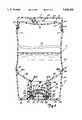
- FIG. 5is a cross-sectional view of the dispensing container, similar to FIG. 1, with the travel cap being supported at the closed end.
- FIG. 6is a cross-sectional view of the dispensing container, similar to FIG. 3, with the travel cap shown sealing the dispensing valve for transport.
- FIG. 7is an exploded detailed view of the dispensing valve.
- FIGS. 1-3disclose a dispensing container 10 of the present invention.
- dispensing container 10includes a travel cap 12, a bottle 16, a dispensing valve 18, and base cap 20.
- the dispensing valve 18selectively dispenses flowable content such as soap, shampoo and other health and beauty products from the bottle 16 of the container 10 when the bottle 16 is squeezed.
- the valve 18restricts the flow of content from the bottle 16 when the bottle 16 is not being squeezed.
- the, base cap 20 and dispensing valve 18are both at a dispensing end 22 of the, container 10 so that the base cap 20 supports the container 10 in an upright inverted position as shown in FIG. 1 to define the base of the container.
- gravityforces the contents in the dispensing container 10 toward the dispensing valve 18 for immediate discharge when pressure is applied to the container 10.
- This featureis particularly useful as the container is emptied, since it would take longer and longer for content to be dispensed if the container were supported at the opposite end of a dispensing opening.
- travel cap 12is selectively positioned at a closed end 23 of the bottle 16 of the container 10 (FIG. 1) and at the dispensing end 22 (FIG. 3).
- the travel cap 12is positioned at the closed end 23 as shown in FIG. 1 when content is to be dispensed through the dispensing valve 18 and at the dispensing end 22 to seal the dispensing valve 18 for transport as shown in FIG. 3.
- the base cap 20is frusto-conical shaped and includes a through opening 24, a drain hole 26, a drain slot 28, a rim ridge 32 and a threaded receptacle 34 (shown in FIG. 1A).
- the base cap 20is formed of a cup-like member having a circular face 36, a sloped cylindrical side wall 38 and a rim 40 defining a housing structure.
- the side wall 38extends from the circular face 36 and is sloped outwardly so that the diameter of the rim 40 is larger than the diameter of the circular face 36.
- the threaded receptacle 34includes a threaded cylindrical wall 42 which extends essentially perpendicularly from face 36.
- rim ridge 32 of base cap 20circumferentially extends about an outer periphery of the face 36 to define an elevated support ridge and a recessed end surface 44.
- the drain slot 28extends through the rim ridge 32 between the recessed end surface 44 and an outer surface of the container 10 to fluidly connect the end surface 44 to the outer surface of the container 10.
- the drain slot 28allows for drainage of fluid trapped under the rim ridge 32 when the dispensing container 10 is supported by the base cap 20, so that mildew and other bacteria is not allowed to grow and collect between the recessed end surface 44 and the rim ridge 32.
- the dispensing valve 18is formed of a silicone membrane 46 including a cross-shaped slit 48.
- the cross shaped slit 48is cut through the silicone membrane 46 to define a plurality of relatively small flaps 50.
- the flaps 50are aligned parallel to the silicone membrane 46 to define a closed position for the dispensing valve 18.
- the flaps 50open such that the flaps 50 are angled relative to the silicone membrane 46 to define an open position for the dispensing valve 18.
- FIG. 4is a cross sectional view of the travel cap 12.
- the travel cap 12is formed of a cup-shaped member having a circular face 58, a cylindrical wall 60, and a rim 62.
- the cylindrical wall 60extends from the periphery of the face 58.
- the wall 60is sloped from the face 58 toward rim 62, to define a larger diameter for the rim 62 than the face 58.
- the rim 62 and wall 60are sized to allow the closed end 23 of the container 10 to be inserted into the interior of the travel cap 12.
- the travel cap 12includes a plurality of lugs 66 (which extend about an inner surface of the cylindrical wall 60) and a plug 68.
- the plug 68includes a circular ring 70 and a lip 72.
- the circular ring 70extends essentially perpendicularly from the face 58 of the travel cap 12.
- Lip 72extend about the periphery of the ring 70 and includes a sloped insertion face 74 and a sloped release face 76.
- FIGS. 5 and 6are cross-sectional views of the container 10 of FIGS. 1 and 3, respectively.
- FIG. 5illustrates the dispensing container 10 with the travel cap 12 supported at the closed upper end 23.
- FIG. 6is a cross-sectional view of the dispensing container 10 with the travel cap 12 sealing the dispensing valve 18 at the dispensing end 22.
- the travel cap 12is secured to the closed end 23 as shown in FIG. 5 by cooperation of the lugs 66 of the travel cap 12 and the circumferential groove 54 extending about the periphery of the closed end 23.
- Lip 52is a curvedly shaped end about the periphery of the closed end 23. Lip 52 flexes the cylindrical wall 60 of the travel cap 12 as the travel cap 12 is forced onto the closed end 23 of the dispensing container 10 to snap fit the lugs 66 into groove 54 of the dispensing container 10.
- a recessed ledge 77 between the bottle 16 and the closed end 23 of the dispensing container 10accommodates the rim 62 of the travel cap 12.
- the recessed ledge 77is dimensioned similar to the thickness of the wall 60 of the travel cap 12 to accommodate the travel cap 12.
- the userpulls and gently twists the travel cap 12 from the closed end 23 to force the travel cap 12 about the curvedly shaped lip 52 to release the lugs 66 of the travel cap 12 from groove 54 of the closed end 23.
- the lugs 66 of travel cap 12are positioned a sufficient distance from the face 58 of the travel cap 12 to allow for clearance between an end face of the closed end 23 and the plug 68 of the travel cap 12.
- the end face of the closed end 23is concave-shaped having a center dip 78.
- the bottle 16 of the dispensing container 10includes an inner cavity 79, a main container segment 80, shoulder 82, having an upper and lower portion 82A and 82B, a threaded neck 86 and mouth 88.
- Flowable contentis filled into the inner cavity 79 of the main container segment 80 of the bottle 16 through mouth 88.
- the main container segment 80is generally cylindrically and slightly concave-shaped.
- the neck 86has a smaller diameter than the main container segment 80 and is connected to the main container segment 80 by the shoulder 82.
- Upper shoulder portion 82Ais adjacent to the main container segment 80 and the lower shoulder portion 82B is adjacent to the neck 86.
- a recessed ledge 89connects the main container segment 80 to the upper shoulder portion 82A.
- the base cap 20is screwed to the bottle 16 to form the dispensing container 10 via cooperation of the threaded receptacle 34 of the base cap 20 and the threaded neck 86 of the bottle 16.
- the depth of the base cap 20is sufficient so that when the neck 86 of the bottle 16 is inserted into receptacle 34 of the base cap 20, the housing (face 36 and cylindrical wall 38) of the base cap 20 encloses the neck 86 and shoulder 82 of the bottle 16 to provide a cover structure for the threaded neck 86 and shoulder 82 of the bottle 16.
- the through opening 24 of the base cap 20is smaller than the mouth 88 of the bottle 16 and aligned therewith when the base cap 20 is screwed to bottle 16 to define the dispensing opening. Fluid is dispensed from the inner cavity 79 of the bottle 16 through the dispensing opening (mouth 88 of the bottle 16 and through opening 24 of the base cap 20).
- the dispensing valve 18is seated in the mouth 88 of the bottle 16 to regulate flow of content, such as shampoos and soaps from the inner cavity 79 through the dispensing opening.
- the rim 40 of the base cap 20abuts against the upper shoulder portion 82A and recessed ledge 89 of the bottle 16.
- the recessed ledge 89is sized relative to the width of the cylindrical side wall 38 of the base cap 20 to provide a smooth transition of the housing of the base cap 20 and the main container segment 80 of the bottle 16.
- the enclosure of the base cap 20 about the neck 86 and the shoulder 82 of the bottle 16defines; a base cavity or housing cavity 93.
- watermay seep through the abutment of the rim 40 of the base cap 20 and the bottle 16 at the upper shoulder portion 82A into the base cavity 93.
- Drain hole 26extends through face 36 of the base cap 20 to allow fluid trapped in the base cavity 93 to drain so that mildew and bacteria do not grow.
- FIG. 6illustrates the travel cap 12 attached to the base cap 20 to seal the container 10 for transport.
- the interior of the travel cap 12is sized to fit over a lower portion of the base cap 20 and the lugs 66 of travel cap 12 frictionally grip the outer surface of the wall 38 of the base cap 20.
- the ring 70 of the plug 68is formed of a flexible material and is sized for insertion into through opening 24 of the base cap 20 to seal the opening 24.
- the lip 72overhangs from the ring 70 so that the diameter of the lip 72 is slightly larger than the through opening 24.
- the height of the ring 70 between the face 58 of the cap 20 and lip 72is sized so that the ring 70 extends through opening 24 and the lip 72 engages an inner surface of the face 36 of the base cap 20 to snap fit the travel cap 12 to the base cap 20 of the container 10.
- the sloped insertion face 74(best shown in FIG. 4) of lip 72 allows for insertion of the circular ring 70 and lip 72 through the through opening 24.
- the sloped insertion face 74contacts the base cap 20 at the through opening 24 to slightly flex the ring 70 for insertion of the ring 70 and lip 72 through the through opening 24.
- the sloped release face 76(best shown in FIG. 4) is slightly sloped to facilitate removal of the travel cap 12. The sloped release face 76 flexes the ring 70 as the cap 12 is pulled from the base cap 20 so that the ring 70 and lip 72 may be slid through the through opening 24 for removal of the cap 12.
- Dispensing valve 18, as shown in relation to FIGS. 5-7,includes the silicone membrane 46, and a first ring support 96 and a second ring support 98.
- the silicone membrane 46is supported between the first ring support 96 and the second ring support 98.
- the silicone membrane 46is preformed into a cup-like member having a base 100, cylindrical wall 102, a support ledge 104, and flange 106.
- the cylindrical wall 102extends from the base 100.
- the support ledge 104extends perpendicularly from an open end of the cylindrical wall 102 (opposite the base 100) about the periphery thereof.
- Flange 106extends essentially perpendicularly from ledge 104.
- the cross slit 48is stamped at the base 100 of the cup-like member.
- the first ring support 96includes a flexible fit ring 108, a flow gate 110, flow gate support legs 112, a flow gate support ring 114, recess 116 (shown in FIGS. 5 & 6) and ring groove 118.
- the second ring support 98includes ring ridge 120 and tongue 122. As best shown in FIGS. 5-6, recess 116 of the first ring support 96 is sized to accommodate and is aligned with flange 106 of the silicone membrane 46. Ring ridge 120 of the second ring support 98 snap fits into ring groove 118 of the first ring support 96 to connect the first and second ring supports 96 and 98 to support the ledge 104 of the silicone membrane 46 therebetween.
- the fit ring 108 of the first ring support 96is dimensioned similar to the mouth 88 of the bottle 16. When assembled, the first ring support 96 is inserted into the mouth 88 so that the fit ring 108 fictionally engages the neck 86 of the bottle 16 to secure the dispensing valve 18 relative to the mouth 88 of bottle 16.
- the second ring support 98is dimensioned similar to an outer surface of the neck 86 of the bottle 1.6. When assembled, the second ring support 98 is seated at an opened end of the neck 86 of the bottle 16. As shown in FIGS. 5 & 6, when the base cap 20 is screwed to the neck 86 of the bottle 16, a portion of the face 36 and a portion of the cylindrical wall 72 of the receptacle 34 of the base cap 20 abut against the second ring support 98 to the lock the dispensing valve 18 within the mouth 88 of the bottle 16.
- the second ring support 98includes a circular tongue 122 which is sized to insert into a corresponding circumferential groove 124 formed about the cylindrical wall 42 of the receptacle 34 of the base cap 20.
- the flow gate 110is a circular plate dimensioned smaller than the diameter of the base 100 of the silicone membrane 46.
- the flow gate 110is supported adjacent to the silicone membrane 46 in the mouth 88 of the bottle 16 to control the flow force of content directly toward the slit 48 to prevent unwanted seepage through the slit 48 of the silicone membrane 46.
- the flow gate 110is supported by the first ring support 96 by the flow gate support ring 114.
- Legs 112connect the flow gate 110 to the flow gate support ring 114. The legs 112 are spaced to allow fluid to flow past the flow gate 110 to be dispensed through the dispensing opening.
- the cap 12, bottle 16 and base cap 20are preferably formed of a high density polyethylene material.
- the silicone membrane 46 and slit 48are dimensioned to restrict flow oil content from the inner cavity 79 of the container 10 until the container 10 is squeezed to dispense content.
- a dispensing container 10having a longitudinal axis along an extent of the container and a diametric axis perpendicular to the longitudinal axis, may be constructed according to the present invention as follows.
- the bottle 16 of the containerincludes a main container segment 80 having a center portion having a diameter A of approximately 2.1 inches and opposed end portions having a diameter B of approximately 2.25 inches to define the concaved shape therefor.
- the neck 86 of the bottle 16has an outer diameter of approximately 0.85 inches and the mouth 88 of the bottle 16 has a diameter of approximately 0.72 inches.
- the upper shoulder portion 82A, adjacent the recessed ledge 89includes a rounded edge having a radius C of approximately 0.1 inches and is slightly sloped at an angle D of approximately 5 degrees relative to the longitudinal axis toward the lower shoulder portion 82B.
- the diameter of the upper shoulder portion 82A at the recessed ledge 89is approximately 2.1 inches.
- the shoulder 82is sloped between the upper shoulder portion 82A and the lower shoulder portion 82B at an angle E of about a 30 degree angle relative to the diametric axis of the bottle 16 to connect the main container segment 80 and the neck 86 of the bottle 16.
- the diameter F of the closed end 23is approximately 2.1 inches.
- the sides of the groove 54 of the closed end 23have a thickness G of approximately 0.04 inches and the width H of a base of the groove 54 is approximately 0.05 inches.
- the sides of the groove 54are formed at an angle I of about 45 degrees, relative to the diametric axis of the bottle 16.
- the lip 52 of the closed end 23includes a rounded end having a radius J of approximately 0.15 inches and a side edge which is sloped inwardly from the groove 54 at an angle K of approximately 5 degrees relative to the longitudinal axis of the bottle 16.
- the center dip 78 of the closed end 23has approximately a 0.1 inch depth.
- the overall height of the bottle 16is approximately 6.2 inches.
- the height of the main container segment 80is approximately 4.62 inches
- shoulder 82is approximately 0.55 inches
- neck 86is approximately 0.65 inches
- closed end 23is 0.40 inches
- lip 52is approximately 0.19 inches.
- the height of shoulder portion 82Ais approximately 0.19 inches.
- the diameter of the through opening 24 of the base cap 20is approximately 0.47 inches and the diameter of the rim 40 of the base cap 20 is 2.2 inches.
- the thickness of cylindrical sidewall 38is approximately 0.045 inches.
- the height of the base cap 20is 1.375 inches and the height of the wall 42 of the receptacle 34 is approximately 0.8 inches.
- the height of the base cap 20 and the extent of the wall 42 of the receptacle 34accommodate for the valve 18 and allow the rim 40 of the base cap 20 to seat at the recessed ledge 89 of the bottle 16.
- the wall 38 of the base cap 20is sloped outwardly from the face 36 toward rim 40 at an angle L of about 5 degrees relative to the longitudinal axis.
- the height of the rim ridge 32 at the periphery of the face 36 of the base cap 20is approximately 0.025 inches.
- the drain holeis approximately 0.080 inches in diameter.
- the width of the drain slot 28is approximately 0.1 inches.
- the diameter of the travel cap 12 at the rim 62is approximately 2.2 inches.
- the height of the travel cap 12is approximately 0.575 inches.
- the wall 60 of the travel cap 12is sloped outwardly from the face 58 to the rim 62 at an angle M of 5 degrees relative to the longitudinal axis.
- the height of the ring 70 and lip 72 of plug 68is approximately 0.125 inches.
- the lugs 66are positioned a distance N of approximately 0.0625 inches below the rim 62 of travel cap 12.
- the thickness O of the lugs 66is approximately 0.11 inches and thickness P of the lugs 66 is approximately 0.05 inches.
- a dispensing container 10which is designed for use in a shower or bathroom.
- the container 10is designed to be supported on slippery wet surfaces and is also designed to allow fluid which has seeped into crevices or cavities of the container to drain so that mildew and other bacteria is not allowed to grow.
- the container 10includes rim ridge 32 about the periphery of the face 36 of the base of the container 10.
- the rim ridge 32defines an elevated support ridge and a recessed end surface 44 for supporting the container 10 on wet surfaces.
- the drain slot 28 through the rim ridge 32 fluidly connecting the recessed end surface 44 to the outer surface of the container 10 and the drain hole 26 through the face 36 fluidly connecting the base cavity 93 to the outer surface of the container 10allow fluid to drain from cavities of the container 10 so that mold and mildew is not allowed to grow.
Landscapes
- Engineering & Computer Science (AREA)
- Mechanical Engineering (AREA)
- Closures For Containers (AREA)
Abstract
Description
Claims (19)
Priority Applications (1)
| Application Number | Priority Date | Filing Date | Title |
|---|---|---|---|
| US08/477,534US5626262A (en) | 1995-06-07 | 1995-06-07 | Dispensing container with drainage passages |
Applications Claiming Priority (1)
| Application Number | Priority Date | Filing Date | Title |
|---|---|---|---|
| US08/477,534US5626262A (en) | 1995-06-07 | 1995-06-07 | Dispensing container with drainage passages |
Publications (1)
| Publication Number | Publication Date |
|---|---|
| US5626262Atrue US5626262A (en) | 1997-05-06 |
Family
ID=23896319
Family Applications (1)
| Application Number | Title | Priority Date | Filing Date |
|---|---|---|---|
| US08/477,534Expired - LifetimeUS5626262A (en) | 1995-06-07 | 1995-06-07 | Dispensing container with drainage passages |
Country Status (1)
| Country | Link |
|---|---|
| US (1) | US5626262A (en) |
Cited By (46)
| Publication number | Priority date | Publication date | Assignee | Title |
|---|---|---|---|---|
| WO1998045184A1 (en)* | 1997-04-09 | 1998-10-15 | The Coca-Cola Company | Dispensing valve closure with inner seal |
| US5934514A (en)* | 1995-08-25 | 1999-08-10 | Aptargroup, Inc. | Dispensing valve closure with inner seal |
| US5944234A (en)* | 1998-01-21 | 1999-08-31 | Aptargroup, Inc. | Dispensing closure for package containing a consumable beverage |
| US5971232A (en)* | 1998-06-03 | 1999-10-26 | Aptargroup, Inc. | Dispensing structure which has a pressure-openable valve retained with folding elements |
| WO2000006456A3 (en)* | 1998-07-28 | 2000-08-03 | Unilever Plc | Container and closure |
| US6223942B1 (en) | 1998-07-28 | 2001-05-01 | Lever Brothers Company, Division Of Conopco, Inc. | Container and closure |
| USD448242S1 (en) | 1999-12-30 | 2001-09-25 | Johnson & Johnson Consumer Companies, Inc. | Trainer cup |
| USD448976S1 (en) | 1999-12-30 | 2001-10-09 | Johnson & Johnson Consumer Companies, Inc. | Pinched trainer cup |
| USD450535S1 (en) | 1999-12-30 | 2001-11-20 | Mcdonough Justin E. | Trainer cup |
| US20020074367A1 (en)* | 2000-12-18 | 2002-06-20 | Kevin Kawakita | Gravity-fed liquid chemical dispenser bottle |
| US6419783B1 (en) | 1999-04-16 | 2002-07-16 | Unilever Home & Personal Care Usa | Container and closure |
| DE10125842A1 (en)* | 2001-05-25 | 2002-12-05 | Hoehensteiger Alois | Dispenser for liquid media such as liquid soap, disinfectants, etc. |
| US6494346B2 (en)* | 2001-01-25 | 2002-12-17 | Seaquist Closures Foreign, Inc. | Inverted package dispensing system |
| US20040000566A1 (en)* | 2002-06-27 | 2004-01-01 | Adam Lowry | Bottom-dispensing liquid soap dispenser |
| US20040065696A1 (en)* | 2002-10-03 | 2004-04-08 | Fletcher Alan D. | Dispenser cap |
| US20040099674A1 (en)* | 1999-12-30 | 2004-05-27 | Mcdonough Justin E. | Elastomeric valve for spill-proof feeding devices |
| US20050035156A1 (en)* | 2003-08-11 | 2005-02-17 | Michael Hersch | Fluid dispensing apparatus |
| US20050150912A1 (en)* | 2004-01-12 | 2005-07-14 | Christopher Casey | Multiple-tap adapter for drink dispenser |
| US20060171857A1 (en)* | 2003-08-11 | 2006-08-03 | Stead Ronald H | Reagent container and slide reaction and retaining tray, and method of operation |
| US20060169719A1 (en)* | 2003-08-11 | 2006-08-03 | Bui Xuan S | Manifold assembly |
| US20060173575A1 (en)* | 2003-08-11 | 2006-08-03 | Gilles Lefebvre | Automated reagent dispensing system and method of operation |
| US20060243756A1 (en)* | 2000-12-18 | 2006-11-02 | Kevin Kawakita | Gravity-fed liquid chemical dispensing bottle |
| US20080035677A1 (en)* | 2004-09-09 | 2008-02-14 | Daansen Warren S | Nozzle tip with slit valve for fluid dispenser |
| US20090283555A1 (en)* | 2008-05-14 | 2009-11-19 | Tablecraft Products Company | Valve top |
| US20090307957A1 (en)* | 2008-06-16 | 2009-12-17 | Gass Kim R | Scent dispersal device |
| US20110000910A1 (en)* | 1997-08-21 | 2011-01-06 | Hakim Nouri E | No-Spill Drinking Cup Apparatus |
| US20110036852A1 (en)* | 1997-08-21 | 2011-02-17 | Hakim Nouri E | No-spill drinking cup apparatus |
| US20120080450A1 (en)* | 2010-10-01 | 2012-04-05 | Conopco, Inc., D/B/A Unilever | Food dispenser |
| KR200463263Y1 (en) | 2011-11-21 | 2012-10-25 | 주식회사 새샘 | Ejection cap of sauce container |
| US20130075430A1 (en)* | 2009-09-11 | 2013-03-28 | Karl Ragnarsson | Containers and methods for dispensing multiple doses of a concentrated liquid, and shelf stable concentrated liquids |
| US8459509B2 (en) | 2006-05-25 | 2013-06-11 | Sakura Finetek U.S.A., Inc. | Fluid dispensing apparatus |
| US8580568B2 (en) | 2011-09-21 | 2013-11-12 | Sakura Finetek U.S.A., Inc. | Traceability for automated staining system |
| US8752732B2 (en) | 2011-02-01 | 2014-06-17 | Sakura Finetek U.S.A., Inc. | Fluid dispensing system |
| USD716142S1 (en) | 2012-06-18 | 2014-10-28 | Conopco, Inc. | Cap |
| US8932543B2 (en) | 2011-09-21 | 2015-01-13 | Sakura Finetek U.S.A., Inc. | Automated staining system and reaction chamber |
| USD739750S1 (en) | 2012-06-18 | 2015-09-29 | Conopco, Inc. | Bottle |
| EP1873068B1 (en) | 2006-06-30 | 2015-10-21 | H. J. Heinz Co. | Condiment bottle |
| WO2016057623A1 (en) | 2014-10-07 | 2016-04-14 | The Procter & Gamble Company | Method of pre-treating articles to be washed in a dishwashing machine |
| USD756234S1 (en) | 2014-09-10 | 2016-05-17 | Celgene Corporation | Bottle with cap |
| USD760590S1 (en) | 2013-01-25 | 2016-07-05 | S.C. Johnson & Son, Inc. | Bottle |
| USD767405S1 (en) | 2015-09-21 | 2016-09-27 | Celgene Corporation | Bottle with cap |
| US10273061B1 (en)* | 2017-12-08 | 2019-04-30 | Tsai-Hui Lin | Container for viscous liquid |
| US20190161253A1 (en)* | 2017-11-30 | 2019-05-30 | The Procter & Gamble Company | Liquid dispenser for an inverted container |
| US11013248B2 (en) | 2012-05-25 | 2021-05-25 | Kraft Foods Group Brands Llc | Shelf stable, concentrated, liquid flavorings and methods of preparing beverages with the concentrated liquid flavorings |
| US20220397106A1 (en)* | 2021-06-10 | 2022-12-15 | Kevin Imai | Fluid Pumping Device |
| US11873133B2 (en) | 2021-04-20 | 2024-01-16 | Drug Plastics & Glass Company, Inc. | Bottle, injection blow molding core rod for the bottle and related method |
Citations (11)
| Publication number | Priority date | Publication date | Assignee | Title |
|---|---|---|---|---|
| US4728006A (en)* | 1984-04-27 | 1988-03-01 | The Procter & Gamble Company | Flexible container including self-sealing dispensing valve to provide automatic shut-off and leak resistant inverted storage |
| US4749108A (en)* | 1986-12-19 | 1988-06-07 | The Procter & Gamble Company | Bimodal storage and dispensing package including self-sealing dispensing valve to provide automatic shut-off and leak-resistant inverted storage |
| EP0296103A2 (en)* | 1987-06-16 | 1988-12-21 | Alfatechnic Patent AG | Plastic closure with central sealing peg |
| US4969581A (en)* | 1989-08-08 | 1990-11-13 | The Procter & Gamble Company | Unequivocal bottom delivery container with self-sealing valve |
| US5033655A (en)* | 1989-02-15 | 1991-07-23 | Liquid Molding Systems Inc. | Dispensing package for fluid products and the like |
| US5060830A (en)* | 1989-02-02 | 1991-10-29 | Owens-Illinois Plastic Products Inc. | Dispensing package for dispensing liquids |
| US5115950A (en)* | 1991-01-14 | 1992-05-26 | Seaquist Closures A Divison Of Pittway Corporation | Dispensing closure with unitary structure for retaining a pressure-actuated flexible valve |
| US5213236A (en)* | 1991-12-06 | 1993-05-25 | Liquid Molding Systems, Inc. | Dispensing valve for packaging |
| US5337877A (en)* | 1989-07-28 | 1994-08-16 | Mars, Inc. | Coin validators |
| WO1994029187A1 (en)* | 1993-06-04 | 1994-12-22 | Billy Nilson | A self-closing arrangement |
| US5409144A (en)* | 1991-12-06 | 1995-04-25 | Liquid Molding Systems Inc. | Dispensing valve for packaging |
- 1995
- 1995-06-07USUS08/477,534patent/US5626262A/ennot_activeExpired - Lifetime
Patent Citations (12)
| Publication number | Priority date | Publication date | Assignee | Title |
|---|---|---|---|---|
| US4728006A (en)* | 1984-04-27 | 1988-03-01 | The Procter & Gamble Company | Flexible container including self-sealing dispensing valve to provide automatic shut-off and leak resistant inverted storage |
| US4749108A (en)* | 1986-12-19 | 1988-06-07 | The Procter & Gamble Company | Bimodal storage and dispensing package including self-sealing dispensing valve to provide automatic shut-off and leak-resistant inverted storage |
| EP0296103A2 (en)* | 1987-06-16 | 1988-12-21 | Alfatechnic Patent AG | Plastic closure with central sealing peg |
| US5060830A (en)* | 1989-02-02 | 1991-10-29 | Owens-Illinois Plastic Products Inc. | Dispensing package for dispensing liquids |
| US5033655A (en)* | 1989-02-15 | 1991-07-23 | Liquid Molding Systems Inc. | Dispensing package for fluid products and the like |
| US5337877A (en)* | 1989-07-28 | 1994-08-16 | Mars, Inc. | Coin validators |
| US4969581A (en)* | 1989-08-08 | 1990-11-13 | The Procter & Gamble Company | Unequivocal bottom delivery container with self-sealing valve |
| US5115950A (en)* | 1991-01-14 | 1992-05-26 | Seaquist Closures A Divison Of Pittway Corporation | Dispensing closure with unitary structure for retaining a pressure-actuated flexible valve |
| US5213236A (en)* | 1991-12-06 | 1993-05-25 | Liquid Molding Systems, Inc. | Dispensing valve for packaging |
| US5339995A (en)* | 1991-12-06 | 1994-08-23 | Liquid Molding Systems, Inc. | Dispensing valve for packaging |
| US5409144A (en)* | 1991-12-06 | 1995-04-25 | Liquid Molding Systems Inc. | Dispensing valve for packaging |
| WO1994029187A1 (en)* | 1993-06-04 | 1994-12-22 | Billy Nilson | A self-closing arrangement |
Non-Patent Citations (6)
| Title |
|---|
| Closure A as shown in photographs 1 2, (prior art).* |
| Closure A as shown in photographs 1-2, (prior art). |
| Closure B as shown in photographs 1 3, (prior art).* |
| Closure B as shown in photographs 1-3, (prior art). |
| Closure C as shown in photographs 1 3, (prior art.* |
| Closure C as shown in photographs 1-3, (prior art. |
Cited By (70)
| Publication number | Priority date | Publication date | Assignee | Title |
|---|---|---|---|---|
| US5934514A (en)* | 1995-08-25 | 1999-08-10 | Aptargroup, Inc. | Dispensing valve closure with inner seal |
| WO1998045184A1 (en)* | 1997-04-09 | 1998-10-15 | The Coca-Cola Company | Dispensing valve closure with inner seal |
| US9010568B2 (en) | 1997-08-21 | 2015-04-21 | Admar International, Inc. | No-spill drinking cup apparatus |
| US20110000910A1 (en)* | 1997-08-21 | 2011-01-06 | Hakim Nouri E | No-Spill Drinking Cup Apparatus |
| US20110036852A1 (en)* | 1997-08-21 | 2011-02-17 | Hakim Nouri E | No-spill drinking cup apparatus |
| US8695841B2 (en) | 1997-08-21 | 2014-04-15 | Luv N' Care, Ltd. | No-spill drinking cup apparatus |
| US8827107B2 (en) | 1997-08-21 | 2014-09-09 | Luv N' Care, Ltd. | No-spill drinking cup apparatus |
| US5944234A (en)* | 1998-01-21 | 1999-08-31 | Aptargroup, Inc. | Dispensing closure for package containing a consumable beverage |
| US5971232A (en)* | 1998-06-03 | 1999-10-26 | Aptargroup, Inc. | Dispensing structure which has a pressure-openable valve retained with folding elements |
| WO2000006456A3 (en)* | 1998-07-28 | 2000-08-03 | Unilever Plc | Container and closure |
| US6223942B1 (en) | 1998-07-28 | 2001-05-01 | Lever Brothers Company, Division Of Conopco, Inc. | Container and closure |
| US6419783B1 (en) | 1999-04-16 | 2002-07-16 | Unilever Home & Personal Care Usa | Container and closure |
| USD463216S1 (en) | 1999-12-30 | 2002-09-24 | Johnson & Johnson Consumer Companies, Inc. | Trainer cup |
| USD452415S1 (en) | 1999-12-30 | 2001-12-25 | Mcdonough Justin E. | Pinched trainer cup |
| USD452116S1 (en) | 1999-12-30 | 2001-12-18 | Mcdonough Justin E. | Trainer cup |
| US20040099674A1 (en)* | 1999-12-30 | 2004-05-27 | Mcdonough Justin E. | Elastomeric valve for spill-proof feeding devices |
| USD450535S1 (en) | 1999-12-30 | 2001-11-20 | Mcdonough Justin E. | Trainer cup |
| USD448976S1 (en) | 1999-12-30 | 2001-10-09 | Johnson & Johnson Consumer Companies, Inc. | Pinched trainer cup |
| USD448242S1 (en) | 1999-12-30 | 2001-09-25 | Johnson & Johnson Consumer Companies, Inc. | Trainer cup |
| US20060243756A1 (en)* | 2000-12-18 | 2006-11-02 | Kevin Kawakita | Gravity-fed liquid chemical dispensing bottle |
| US20020074367A1 (en)* | 2000-12-18 | 2002-06-20 | Kevin Kawakita | Gravity-fed liquid chemical dispenser bottle |
| US6494346B2 (en)* | 2001-01-25 | 2002-12-17 | Seaquist Closures Foreign, Inc. | Inverted package dispensing system |
| DE10125842A1 (en)* | 2001-05-25 | 2002-12-05 | Hoehensteiger Alois | Dispenser for liquid media such as liquid soap, disinfectants, etc. |
| DE10125842B4 (en)* | 2001-05-25 | 2005-06-09 | Höhensteiger, Alois | Dispensers for liquid media such as liquid soap, disinfectants etc. |
| US6705492B2 (en)* | 2002-06-27 | 2004-03-16 | Method Products, Inc. | Bottom-dispensing liquid soap dispenser |
| US20040000566A1 (en)* | 2002-06-27 | 2004-01-01 | Adam Lowry | Bottom-dispensing liquid soap dispenser |
| US20040065696A1 (en)* | 2002-10-03 | 2004-04-08 | Fletcher Alan D. | Dispenser cap |
| US20060173575A1 (en)* | 2003-08-11 | 2006-08-03 | Gilles Lefebvre | Automated reagent dispensing system and method of operation |
| US20060169719A1 (en)* | 2003-08-11 | 2006-08-03 | Bui Xuan S | Manifold assembly |
| US20050035156A1 (en)* | 2003-08-11 | 2005-02-17 | Michael Hersch | Fluid dispensing apparatus |
| US7501283B2 (en) | 2003-08-11 | 2009-03-10 | Sakura Finetek U.S.A., Inc. | Fluid dispensing apparatus |
| US7744817B2 (en) | 2003-08-11 | 2010-06-29 | Sakura Finetek U.S.A., Inc. | Manifold assembly |
| US7767152B2 (en) | 2003-08-11 | 2010-08-03 | Sakura Finetek U.S.A., Inc. | Reagent container and slide reaction retaining tray, and method of operation |
| US20060171857A1 (en)* | 2003-08-11 | 2006-08-03 | Stead Ronald H | Reagent container and slide reaction and retaining tray, and method of operation |
| US9518899B2 (en) | 2003-08-11 | 2016-12-13 | Sakura Finetek U.S.A., Inc. | Automated reagent dispensing system and method of operation |
| US20050150912A1 (en)* | 2004-01-12 | 2005-07-14 | Christopher Casey | Multiple-tap adapter for drink dispenser |
| US9254498B2 (en) | 2004-09-09 | 2016-02-09 | Warren S. Daansen | Nozzle tip with slit valve for fluid dispenser |
| US9714714B2 (en) | 2004-09-09 | 2017-07-25 | Warren S. Daansen | Nozzle tip with slit valve for fluid dispenser |
| US20080035677A1 (en)* | 2004-09-09 | 2008-02-14 | Daansen Warren S | Nozzle tip with slit valve for fluid dispenser |
| US8899449B2 (en)* | 2004-09-09 | 2014-12-02 | Warren S. Daansen | Nozzle tip with slit valve for fluid dispenser |
| US8459509B2 (en) | 2006-05-25 | 2013-06-11 | Sakura Finetek U.S.A., Inc. | Fluid dispensing apparatus |
| US9914124B2 (en) | 2006-05-25 | 2018-03-13 | Sakura Finetek U.S.A., Inc. | Fluid dispensing apparatus |
| EP1873068B1 (en) | 2006-06-30 | 2015-10-21 | H. J. Heinz Co. | Condiment bottle |
| US8162186B2 (en)* | 2008-05-14 | 2012-04-24 | Tablecraft Products Company | Valve top |
| US20090283555A1 (en)* | 2008-05-14 | 2009-11-19 | Tablecraft Products Company | Valve top |
| US20090307957A1 (en)* | 2008-06-16 | 2009-12-17 | Gass Kim R | Scent dispersal device |
| US20130075430A1 (en)* | 2009-09-11 | 2013-03-28 | Karl Ragnarsson | Containers and methods for dispensing multiple doses of a concentrated liquid, and shelf stable concentrated liquids |
| US20120080450A1 (en)* | 2010-10-01 | 2012-04-05 | Conopco, Inc., D/B/A Unilever | Food dispenser |
| US8752732B2 (en) | 2011-02-01 | 2014-06-17 | Sakura Finetek U.S.A., Inc. | Fluid dispensing system |
| US9016526B2 (en) | 2011-02-01 | 2015-04-28 | Sakura Finetek U.S.A., Inc. | Fluid dispensing system |
| US12281970B2 (en) | 2011-09-21 | 2025-04-22 | Sakura Finetek U.S.A., Inc. | Automated staining system and reaction chamber |
| US8580568B2 (en) | 2011-09-21 | 2013-11-12 | Sakura Finetek U.S.A., Inc. | Traceability for automated staining system |
| US10295444B2 (en) | 2011-09-21 | 2019-05-21 | Sakura Finetek U.S.A., Inc. | Automated staining system and reaction chamber |
| US9005980B2 (en) | 2011-09-21 | 2015-04-14 | Sakura Finetek U.S.A., Inc. | Traceability for automated staining system |
| US8932543B2 (en) | 2011-09-21 | 2015-01-13 | Sakura Finetek U.S.A., Inc. | Automated staining system and reaction chamber |
| KR200463263Y1 (en) | 2011-11-21 | 2012-10-25 | 주식회사 새샘 | Ejection cap of sauce container |
| US11013248B2 (en) | 2012-05-25 | 2021-05-25 | Kraft Foods Group Brands Llc | Shelf stable, concentrated, liquid flavorings and methods of preparing beverages with the concentrated liquid flavorings |
| USD739750S1 (en) | 2012-06-18 | 2015-09-29 | Conopco, Inc. | Bottle |
| USD716142S1 (en) | 2012-06-18 | 2014-10-28 | Conopco, Inc. | Cap |
| USD761656S1 (en) | 2013-01-25 | 2016-07-19 | S. C. Johnson & Son, Inc. | Bottle |
| USD828163S1 (en) | 2013-01-25 | 2018-09-11 | S.C. Johnson & Son, Inc. | Bottle |
| USD760590S1 (en) | 2013-01-25 | 2016-07-05 | S.C. Johnson & Son, Inc. | Bottle |
| USD756234S1 (en) | 2014-09-10 | 2016-05-17 | Celgene Corporation | Bottle with cap |
| WO2016057623A1 (en) | 2014-10-07 | 2016-04-14 | The Procter & Gamble Company | Method of pre-treating articles to be washed in a dishwashing machine |
| USD767405S1 (en) | 2015-09-21 | 2016-09-27 | Celgene Corporation | Bottle with cap |
| US20190161253A1 (en)* | 2017-11-30 | 2019-05-30 | The Procter & Gamble Company | Liquid dispenser for an inverted container |
| US10611531B2 (en)* | 2017-11-30 | 2020-04-07 | The Procter & Gamble Company | Liquid dispenser for an inverted container |
| US10273061B1 (en)* | 2017-12-08 | 2019-04-30 | Tsai-Hui Lin | Container for viscous liquid |
| US11873133B2 (en) | 2021-04-20 | 2024-01-16 | Drug Plastics & Glass Company, Inc. | Bottle, injection blow molding core rod for the bottle and related method |
| US20220397106A1 (en)* | 2021-06-10 | 2022-12-15 | Kevin Imai | Fluid Pumping Device |
Similar Documents
| Publication | Publication Date | Title |
|---|---|---|
| US5626262A (en) | Dispensing container with drainage passages | |
| US5655687A (en) | Base end dispensing container with travel cap | |
| US7261221B2 (en) | Inverted dispensing system and apparatus | |
| RU2295482C2 (en) | Device for distributing and batching | |
| US7731066B2 (en) | Closure | |
| CA2278078C (en) | Hinged cap and cap body | |
| US8087547B1 (en) | Dispensing devices with bottom outlet for dispensing viscous liquids | |
| US4022352A (en) | Container cover and safety closure | |
| US7195138B2 (en) | Container closure with biased closed valve | |
| AU748025B2 (en) | Container valve | |
| JP2002526343A (en) | Lid with container and supply valve and releasable separate internal seal for shipping | |
| IE910773A1 (en) | Squeezable dispenser apparatus | |
| US20070114246A1 (en) | Inverted dispensing system and apparatus | |
| JPH03124568A (en) | Distribution container for fluid commodity | |
| HU224043B1 (en) | Seal assembly for selective dispensing of flowable material | |
| JP2964167B2 (en) | Automatic closed dispenser for containers containing liquid or pasty products | |
| RU2225817C2 (en) | Liquid container | |
| JP3626411B2 (en) | Beverage container | |
| JP4261086B2 (en) | Refillable container | |
| WO1999064313A1 (en) | A dispenser capsule for containers of liquid or semiliquid products | |
| US20030057237A1 (en) | Reversing trap container closure | |
| US6578744B2 (en) | Watertight tube closure | |
| EP0701523A1 (en) | Clog-resistant toggle disk closure | |
| JP3830741B2 (en) | Cream-like dispensing containers | |
| JPH0118117Y2 (en) |
Legal Events
| Date | Code | Title | Description |
|---|---|---|---|
| AS | Assignment | Owner name:APTARGROUP, INC., ILLINOIS Free format text:ASSIGNMENT OF ASSIGNORS INTEREST;ASSIGNOR:LAY, DIETER F.;REEL/FRAME:007736/0425 Effective date:19951015 | |
| AS | Assignment | Owner name:DRUG PLASTICS & GLASS COMPANY, INC., PENNSYLVANIA Free format text:ASSIGNMENT OF ASSIGNORS INTEREST;ASSIGNOR:BENDER, THOMAS M.;REEL/FRAME:007834/0880 Effective date:19960123 Owner name:REDMOND PRODUCTS, INC., MINNESOTA Free format text:ASSIGNMENT OF ASSIGNORS INTEREST;ASSIGNOR:DRUG PLASTICS & GLASS COMPANY, INC.;REEL/FRAME:007834/0889 Effective date:19960123 | |
| AS | Assignment | Owner name:REDMOND PRODUCTS, INC., MINNESOTA Free format text:ASSIGNMENT OF ASSIGNORS INTEREST;ASSIGNOR:FITTEN, TIMOTHY E.;REEL/FRAME:008340/0820 Effective date:19961213 | |
| STCF | Information on status: patent grant | Free format text:PATENTED CASE | |
| CC | Certificate of correction | ||
| AS | Assignment | Owner name:BRISTOL-MYERS SQUIBB COMPANY, NEW YORK Free format text:ASSIGNMENT OF ASSIGNORS INTEREST;ASSIGNOR:REDMOND PRODUCTS, INC.;REEL/FRAME:009257/0335 Effective date:19980603 | |
| FEPP | Fee payment procedure | Free format text:PAYOR NUMBER ASSIGNED (ORIGINAL EVENT CODE: ASPN); ENTITY STATUS OF PATENT OWNER: LARGE ENTITY | |
| FPAY | Fee payment | Year of fee payment:4 | |
| AS | Assignment | Owner name:CLAIROL INCORPORATED, CONNECTICUT Free format text:ASSIGNMENT OF ASSIGNORS INTEREST;ASSIGNOR:BRISTOL-MYERS SQUIBB COMPANY;REEL/FRAME:012813/0803 Effective date:20011210 | |
| AS | Assignment | Owner name:SEAQUIST CLOSURES FOREIGN, INC., ILLINOIS Free format text:ASSIGNMENT OF ASSIGNORS INTEREST;ASSIGNOR:APTARGROUP, INC.;REEL/FRAME:014172/0157 Effective date:20030421 | |
| FPAY | Fee payment | Year of fee payment:8 | |
| FPAY | Fee payment | Year of fee payment:12 |