US5626191A - Oilfield in-situ combustion process - Google Patents
Oilfield in-situ combustion processDownload PDFInfo
- Publication number
- US5626191A US5626191AUS08/494,300US49430095AUS5626191AUS 5626191 AUS5626191 AUS 5626191AUS 49430095 AUS49430095 AUS 49430095AUS 5626191 AUS5626191 AUS 5626191A
- Authority
- US
- United States
- Prior art keywords
- reservoir
- wells
- injection
- production
- oil
- Prior art date
- Legal status (The legal status is an assumption and is not a legal conclusion. Google has not performed a legal analysis and makes no representation as to the accuracy of the status listed.)
- Expired - Lifetime
Links
- 238000002485combustion reactionMethods0.000titleclaimsabstractdescription50
- 238000011065in-situ storageMethods0.000titleclaimsdescription6
- 238000004519manufacturing processMethods0.000claimsabstractdescription65
- 238000002347injectionMethods0.000claimsabstractdescription58
- 239000007924injectionSubstances0.000claimsabstractdescription58
- 238000000034methodMethods0.000claimsabstractdescription22
- 230000008569processEffects0.000claimsabstractdescription17
- 238000006073displacement reactionMethods0.000claimsdescription7
- 239000012530fluidSubstances0.000claimsdescription6
- XLYOFNOQVPJJNP-UHFFFAOYSA-NwaterSubstancesOXLYOFNOQVPJJNP-UHFFFAOYSA-N0.000claimsdescription5
- 230000000977initiatory effectEffects0.000claimsdescription3
- 238000013459approachMethods0.000claimsdescription2
- 239000004568cementSubstances0.000claimsdescription2
- 230000001902propagating effectEffects0.000claims1
- 230000000644propagated effectEffects0.000abstractdescription4
- 239000004576sandSubstances0.000description29
- 239000003921oilSubstances0.000description21
- 239000007789gasSubstances0.000description11
- 210000003371toeAnatomy0.000description9
- 230000005484gravityEffects0.000description6
- 239000000203mixtureSubstances0.000description5
- 239000000567combustion gasSubstances0.000description4
- 238000010438heat treatmentMethods0.000description3
- 238000011084recoveryMethods0.000description3
- IJGRMHOSHXDMSA-UHFFFAOYSA-NAtomic nitrogenChemical compoundN#NIJGRMHOSHXDMSA-UHFFFAOYSA-N0.000description2
- QVGXLLKOCUKJST-UHFFFAOYSA-Natomic oxygenChemical compound[O]QVGXLLKOCUKJST-UHFFFAOYSA-N0.000description2
- 230000008901benefitEffects0.000description2
- 230000015572biosynthetic processEffects0.000description2
- 229930195733hydrocarbonNatural products0.000description2
- 150000002430hydrocarbonsChemical class0.000description2
- 239000001301oxygenSubstances0.000description2
- 229910052760oxygenInorganic materials0.000description2
- 238000005204segregationMethods0.000description2
- 229910001220stainless steelInorganic materials0.000description2
- 239000010935stainless steelSubstances0.000description2
- 230000009471actionEffects0.000description1
- 239000008186active pharmaceutical agentSubstances0.000description1
- XAGFODPZIPBFFR-UHFFFAOYSA-NaluminiumChemical compound[Al]XAGFODPZIPBFFR-UHFFFAOYSA-N0.000description1
- 229910052782aluminiumInorganic materials0.000description1
- 239000000571cokeSubstances0.000description1
- 230000001186cumulative effectEffects0.000description1
- 238000010586diagramMethods0.000description1
- 230000000694effectsEffects0.000description1
- 210000003414extremityAnatomy0.000description1
- 239000000295fuel oilSubstances0.000description1
- 238000009413insulationMethods0.000description1
- 238000011835investigationMethods0.000description1
- 239000007788liquidSubstances0.000description1
- 229910052757nitrogenInorganic materials0.000description1
- 230000035699permeabilityEffects0.000description1
- 239000000843powderSubstances0.000description1
- 230000002028prematureEffects0.000description1
- 230000004044responseEffects0.000description1
- 230000002000scavenging effectEffects0.000description1
- 239000002904solventSubstances0.000description1
- 229910052902vermiculiteInorganic materials0.000description1
- 235000019354vermiculiteNutrition0.000description1
- 239000010455vermiculiteSubstances0.000description1
Images


Classifications
- E—FIXED CONSTRUCTIONS
- E21—EARTH OR ROCK DRILLING; MINING
- E21B—EARTH OR ROCK DRILLING; OBTAINING OIL, GAS, WATER, SOLUBLE OR MELTABLE MATERIALS OR A SLURRY OF MINERALS FROM WELLS
- E21B43/00—Methods or apparatus for obtaining oil, gas, water, soluble or meltable materials or a slurry of minerals from wells
- E21B43/16—Enhanced recovery methods for obtaining hydrocarbons
- E21B43/24—Enhanced recovery methods for obtaining hydrocarbons using heat, e.g. steam injection
- E21B43/243—Combustion in situ
- E—FIXED CONSTRUCTIONS
- E21—EARTH OR ROCK DRILLING; MINING
- E21B—EARTH OR ROCK DRILLING; OBTAINING OIL, GAS, WATER, SOLUBLE OR MELTABLE MATERIALS OR A SLURRY OF MINERALS FROM WELLS
- E21B43/00—Methods or apparatus for obtaining oil, gas, water, soluble or meltable materials or a slurry of minerals from wells
- E21B43/30—Specific pattern of wells, e.g. optimising the spacing of wells
- E21B43/305—Specific pattern of wells, e.g. optimising the spacing of wells comprising at least one inclined or horizontal well
Definitions
- This inventionrelates to an in-situ combustion process for recovering hydrocarbons from an underground reservoir. More particularly, it relates to a process in which the production wells each have a horizontal leg and these legs are positioned perpendicularly to and in the path of a laterally extending and advancing combustion front.
- In-situ combustion processesare applied for the purpose of heating heavy oil, to mobilize it and drive it to an open production well for recovery.
- the usual technique usedinvolves providing spaced apart vertical injection and production wells completed in a reservoir.
- an injection wellwill be located within a pattern of surrounding production wells. Air is injected into the formation, the mixture of air and hydrocarbons is ignited, a combustion front is generated in the formation and this resulting combustion front is advanced outwardly toward the production wells.
- a row of injection wellsmay feed air to a laterally extending combustion front which advances as a line drive toward a parallel row of production wells.
- the inventionin its preferred form, incorporates aspects of two processes which are known in the art.
- an open production wellhaving a horizontal leg positioned low in the reservoir so that the well extends generally perpendicularly to and lies in the path of the front and has its furthest extremity ("toe") spaced from but adjacent to the injection source;
- the production wellprovides a low pressure sink and outlet that functions to induce the front to advance in a guided and controlled fashion, first towards the toe and then along the length of the horizontal leg--under these circumstances, the front has been found to remain generally stable and upright and is characterized by a relatively high sweep efficiency;
- combustion gasesCO 2 , CO, H 2 O
- An oil upgrading zoneis formed immediately ahead of the front. The draining oil tends to keep the bore of the horizontal leg full, so there is little opportunity for unused oxygen to be produced through the production well until the front has advanced the length of the leg;
- the heated oildrains readily into the production well for production therethrough.
- the present procedure involving a horizontal produceris found to be characterized by the advantage that the combustion front always intercepts the horizontal leg of the horizontal well at the toe point, rather than at a location along the length of the leg.
- an important feature of the inventionis that the properly oriented, open horizontal leg of the production well functions to directionally guide and stabilize the advancing displacement front. There is a likelihood that this feature could beneficially be used with a steam, partially miscible gas drive or miscible solvent gas drive to control and stabilize the advancing displacement front which is functioning to reduce the viscosity of the oil directly in front of it.
- the inventionis a process for reducing the viscosity of oil in an underground reservoir and driving it to a production well for recovery, comprising: providing a well, completed relatively high in the reservoir, for injecting a gaseous fluid into the reservoir to form an advancing, laterally extending displacement front operative to reduce the viscosity of reservoir oil; providing at least one open production well having a horizontal leg completed relatively low in the reservoir and positioned substantially perpendicular to and in the path of the advancing front; injecting the fluid through the well and advancing the displacement front along the leg; and producing the production well to recover oil from the reservoir.
- FIGS. 1a and 1bare top plan and side views schematically showing a sand pack with simulated injection and production wells completed in a common horizontal plane, as was the case in experimental run 1-D reported on below;
- FIGS. 2a and 2bare top plan and side views schematically showing a sand pack with simulated vertical injection well and perpendicular, horizontal production wells completed high and low in the pack, respectively, as was the case in experimental run 2-D reported on below;
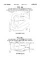
- FIG. 3is a perspective view schematically showing a sand pack with a linear array of simulated injection wells and a simulated perpendicular, horizontal well, completed high and low respectively in the pack, as was the case in experimental runs 3-D and 4-W reported on below;
- FIGS. 4a and 4bare top plan and side views schematically showing a staggered arrangement of simulated wells completed in the sand pack with a vertical injection well and a pair of parallel, spaced apart, perpendicular, horizontal wells, completed high and low respectively in the pack, as was the case in experimental run 5-D reported on below;
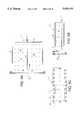
- FIGS. 5a, 5b and 5care top plan, side and end views of a test cell used in the experimental runs reported on below;
- FIG. 6is a flow diagram showing the laboratory set-up, including the test cell of FIGS. 5a-5C, used to conduct the experimental runs reported on below;
- FIGS. 7a and 7bare isotherm maps developed in the sand pack during run 1-D (prior art configuration), taken along the horizontal and vertical mid-planes respectively;
- FIGS. 8a and 8bare the isotherm maps developed in the sand pack during run 2-D, taken along the horizontal and vertical mid-planes respectively;
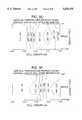
- FIGS. 9a and 9bare the isotherm maps developed in the sand pack after 45 minutes of combustion during run 3-D, taken along horizontal planes close to the top and bottom of the pack, respectively;
- FIGS. 9c, 9d, 9e and 9fare the isotherm maps developed in the sand pack along the vertical mid-plane after 45, 240, 360 and 460 minutes of combustion, respectively, during run 3-D;
- FIG. 10is a plot showing the cumulative production of the oil in place (expressed in percent) for runs 1-D, 2-D and 5-D;
- FIG. 11is a plan view showing a preferred field embodiment of the well layout
- FIG. 12is a side cross-section of the well arrangement of FIG. 11.
- FIG. 13is a perspective view of the reservoir in the injection well and production well layout.
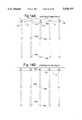
- FIGS. 14a, 14b, 14c, 14d, 14e and 14fillustrate various phases of the combustion process according to the layout shown in FIGS. 11 and 12.
- the inventionwas developed in the course of carrying out an experimental investigation involving test runs carried out in a test cell or three dimensional physical model.
- a test cell 1shown in FIGS. 5a, 5b, 5c and 6, was provided.
- the cellcomprised a rectangular, closed, thin-walled stainless steel box 2.
- the box 2formed a chamber 3 having an area of 40 square centimetres and height of 10 centimetres.
- the thickness of each box wallwas 4 millimetres.
- the chamber 3was filled with a sand pack 4 consisting of a mixture of sand, oil and water.
- the composition of the uniform mixture charged into the chamber 3was:
- the porosity of the sand pack 4was about 30% and the permeability was about 10 darcys.
- the loaded cell box 2was placed inside a larger aluminum box 5 and the space between them was filled with vermiculite powder insulation.
- thermocouples 6positioned at 6 cm intervals as shown in FIGS. 5a, 5b, 5c and 6, extended through the wall of the cell 1 into the sand pack 4, for measuring the three dimensional temperature distribution in the sand pack 4.
- the cell 1was wound with heating tape (not shown). This heat source was controlled manually, on demand, in response to the observed combustion peak temperature and adjacent wall temperature values. The temperature at the wall of the cell was kept a few degrees ° C. less than the temperature inside the sand, close to the wall. In this way, the quasi-adiabatic character of the run was assured.
- a cell heater 7was embedded in the top section of the sand pack 4 at the air injection end, for raising the temperature in the region of the injection well 8 to ignition temperature.
- One or more simulated air injection wells 8were provided at the injection end of the cell 1.
- a simulated production well 9was provided at the opposite or production end of the cell 1.
- FIGS. 1a, 1b, 2a, 2b, 3, 4a and 4bThe positioning and vertical or horizontal disposition of the wells 8, 9 are shown schematically in FIGS. 1a, 1b, 2a, 2b, 3, 4a and 4b for the five test runs reported on below.
- FIGS. 1a, 1b for run 1-Dthe air injection and production wells 8, 9 were short and coplanar. They were both completed under the horizontal mid-plane of the sand pack 4. This arrangement simulated vertical injection and production wells completed at about the same depth.
- FIGS. 2a, 2b for run 2-Dthe air injection well 8 was short and positioned relatively high in the sand pack 4.
- the production well 9was horizontal, elongated, positioned low in the sand pack 4 relative to the injection well 8 and positioned with its toe 10 adjacent to but spaced from the injection well.
- FIG. 3 for runs 3-D and 4-Wa row 11 of vertical injection wells 8, positioned laterally across the sand pack 4, were provided.
- the injection wellswere located relatively high in the sand pack.
- the production well 9was horizontal, elongated, positioned low in the sand pack and had its toe adjacent to but spaced from the injection wells.
- a single vertical air injection well 8was provided high in the sand pack 4 and a pair of horizontal production wells 9 were provided low in the pack.
- the production wellswere laterally spaced relative to the injection well, to provide a staggered line drive system.
- All of the horizontal production wells 9were arranged to be generally perpendicular to a laterally extending combustion front developed at the injection source. However, the toe 10 of the production well was spaced horizontally away from a vertical projection of the injection well.
- Each of the injection and production wells 8, 9were formed of perforated stainless steel tubing having a bore 4 mm in diameter.
- the tubingwas covered with 100 gauge wire mesh (not shown) to exclude sand from entering the tubing bore.
- the combustion cell 1was integrated into a conventional laboratory system shown in FIG. 6. The major components of this system are now shortly described.
- the line 20was sequentially connected with a gas dryer 21, mass flowmeter 22 and pressure gauge 23 before reaching the injection well 8.
- Nitrogencould be supplied to the injection well 8 from a tank 24 connected to line 20.
- Watercould be supplied to the injection well 8 from a tank 27 by a pump 25 through line 26.
- Line 26was connected with line 20 downstream of the pressure gauge 23.
- a temperature controller 28controlled the ignition heater 7.
- the produced fluidspassed through a line 30 connected with a separator 31. Gases separated from the produced fluid and passed out of the separator 31 through an overhead line 32 controlled by a back pressure regulator 33.
- the regulator 33maintained a constant pressure in the test cell 1.
- the volume of the produced gaswas measured by a wet test meter 34 connected to line 32.
- the liquid leaving the separatorwas collected in a cylinder 40.
- Part of the produced gaswas passed through an oxygen analyzer 36 and gas chromatograph 37. Temperature data from the thermocouples 6 was collected by a computer 38 and gas composition data was collected from the analyzer 36 and gas chromatograph 37 by an integrator 39.
- the analysiscomprised a physical removal of successive vertical layers of the sandpack at 3 cm intervals and determining the extent of the burned zone by measuring the oil and coke content. In this way the volumetric sweep of the burning front was determined post-mortem and compared with that obtained from the peak temperature profiles during the run.
- FIGS. 7a and 7bshow the isotherm or temperature contour maps developed along the horizontal mid-plane and the central vertical mid-plane, respectively, in the sand pack after 930 minutes of combustion during run 1-D, using the well configuration of FIGS. 1a and 1b. (This run was carried out using conventional vertical well placement.)
- FIGS. 8a and 8bshow isotherm maps developed along the horizontal mid-plane and the central vertical mid-plane, respectively, in the sand pack after 999 minutes of combustion during run 2-D, using the well configuration of FIGS. 2a and 2b. As shown, the isotherms indicate that the combustion front was substantially wider than that of Run 1 and more upright.
- FIGS. 9a and 9bshow isotherm maps developed along horizontal planes at the top and bottom of the sand pack after 45 minutes of combustion during Run 3-D, using the well configuration of FIG. 3.
- FIGS. 9c, 9d, 9e and 9fshow isotherm maps developed along the central vertical plane of the sand pack after 45, 240, 360 and 460 minutes respectively.
- the isothermsdemonstrate that the combustion front generated by the row of injection wells extended laterally, remained generally linear and was generally upright throughout the test. Stated otherwise, the lateral and vertical sweep was much improved relative to that of Run 1-D. This run 3-D demonstrated the preferred form of the invention.
- a reservoir 100is characterized by a downward dip and lateral strike.
- a row 101 of vertical air injection wells 102is completed high in the reservoir 100 along the strike.
- At least two rows 103, 104 of production wells 105, 106, having generally horizontal legs 107,are completed low in the reservoir and down dip from the injection wells, with their toes 108 closest to the injection wells 102.
- the toes 108 of the row 103 of production wells 105are spaced down dip from a vertical projection of the injection wells 102.
- the second row 104 of production wells 106is spaced down dip from the first row 103.
- the distance between wells, within a rowis considerably lower than the distance between adjacent rows.
- a generally linear combustion front Cis generated in the reservoir 100 by injecting air through every second well 110 of the injection wells 102.
- a generally linear lateral combustion frontis developed by initiating combustion at every second well 110 and advancing these fronts laterally until the other unused wells 102 are intercepted by the combustion front C and by keeping the horizontal production wells 105, 106 closed.
- airis injected through all the wells 102 (FIG. 14b) in order to link these separate fronts to form a single front C.
- the front Cis then propagated down dip (FIGS.
- the horizontal legs 107 of the production wells 105are generally perpendicular to the front C.
- the production wells 105are open during this step, to create a low pressure sink to induce the front to advance along their horizontal legs 107 and to provide an outlet for the heated oil.
- the wellis closed in.
- the horizontal legs 107 of the closed-in wells 105are then filled with cement 111 (FIG. 14e).
- the wells 105are then perforated 112 high in the reservoir 100 (FIG. 14f) and converted to air injection, thereby continuing the propagation of a combustion front toward the second row 104 of production wells 106.
- the first row 101 of injection wellsis converted to water injection, for scavenging heat in the burnt out zone and bringing it ahead of the combustion zone. This process is repeated as the front progresses through the various rows of production wells.
Landscapes
- Life Sciences & Earth Sciences (AREA)
- Engineering & Computer Science (AREA)
- Geology (AREA)
- Mining & Mineral Resources (AREA)
- Physics & Mathematics (AREA)
- Environmental & Geological Engineering (AREA)
- Fluid Mechanics (AREA)
- General Life Sciences & Earth Sciences (AREA)
- Geochemistry & Mineralogy (AREA)
- Production Of Liquid Hydrocarbon Mixture For Refining Petroleum (AREA)
- Gas Burners (AREA)
Abstract
Description
TABLE I ______________________________________ Average Gravity Con- Volume Air-Oil (°API) Run figuration Swept % Ratio (SM.sup.3 /M.sup.3 Of Produced Oil ______________________________________ 1-D FIG. 1 58.7 2045 14 2-D FIG. 2 53.0 1960 19-21 3-D FIG. 3 66 -- 19-21 4-W FIG. 3 77 923 19-21 5-D FIG. 4 69.5 1554 15 ______________________________________ Legend: D = dry in situ combustion W = moderate wet combustion
Claims (7)
Priority Applications (2)
| Application Number | Priority Date | Filing Date | Title |
|---|---|---|---|
| US08/494,300US5626191A (en) | 1995-06-23 | 1995-06-23 | Oilfield in-situ combustion process |
| CA002176639ACA2176639C (en) | 1995-06-23 | 1996-05-15 | Oilfield in-situ combustion process |
Applications Claiming Priority (1)
| Application Number | Priority Date | Filing Date | Title |
|---|---|---|---|
| US08/494,300US5626191A (en) | 1995-06-23 | 1995-06-23 | Oilfield in-situ combustion process |
Publications (1)
| Publication Number | Publication Date |
|---|---|
| US5626191Atrue US5626191A (en) | 1997-05-06 |
Family
ID=23963915
Family Applications (1)
| Application Number | Title | Priority Date | Filing Date |
|---|---|---|---|
| US08/494,300Expired - LifetimeUS5626191A (en) | 1995-06-23 | 1995-06-23 | Oilfield in-situ combustion process |
Country Status (2)
| Country | Link |
|---|---|
| US (1) | US5626191A (en) |
| CA (1) | CA2176639C (en) |
Cited By (82)
| Publication number | Priority date | Publication date | Assignee | Title |
|---|---|---|---|---|
| WO1999030002A1 (en)* | 1997-12-11 | 1999-06-17 | Petroleum Recovery Institute | Oilfield in situ hydrocarbon upgrading process |
| WO2000014380A1 (en)* | 1998-09-02 | 2000-03-16 | Alberta Research Council Inc. | Process for recovery of oil |
| US6167966B1 (en)* | 1998-09-04 | 2001-01-02 | Alberta Research Council, Inc. | Toe-to-heel oil recovery process |
| US20020053432A1 (en)* | 2000-04-24 | 2002-05-09 | Berchenko Ilya Emil | In situ thermal processing of a hydrocarbon containing formation using repeating triangular patterns of heat sources |
| US20030131994A1 (en)* | 2001-04-24 | 2003-07-17 | Vinegar Harold J. | In situ thermal processing and solution mining of an oil shale formation |
| US20030201098A1 (en)* | 2001-10-24 | 2003-10-30 | Karanikas John Michael | In situ recovery from a hydrocarbon containing formation using one or more simulations |
| US6729394B1 (en)* | 1997-05-01 | 2004-05-04 | Bp Corporation North America Inc. | Method of producing a communicating horizontal well network |
| US20040140096A1 (en)* | 2002-10-24 | 2004-07-22 | Sandberg Chester Ledlie | Insulated conductor temperature limited heaters |
| US20040154793A1 (en)* | 2001-03-15 | 2004-08-12 | Zapadinski Alexei Leonidovich | Method for developing a hydrocarbon reservoir (variants) and complex for carrying out said method (variants) |
| US20050082057A1 (en)* | 2003-10-17 | 2005-04-21 | Newton Donald E. | Recovery of heavy oils through in-situ combustion process |
| US20050150816A1 (en)* | 2004-01-09 | 2005-07-14 | Les Gaston | Bituminous froth inline steam injection processing |
| US20050178549A1 (en)* | 2004-02-18 | 2005-08-18 | Eoff Larry S. | Methods of reducing the permeabilities of horizontal well bore sections |
| US6948562B2 (en) | 2001-04-24 | 2005-09-27 | Shell Oil Company | Production of a blending agent using an in situ thermal process in a relatively permeable formation |
| WO2005121504A1 (en)* | 2004-06-07 | 2005-12-22 | Archon Technologies Ltd. | Oilfield enhanced in situ combustion process |
| US7011154B2 (en) | 2000-04-24 | 2006-03-14 | Shell Oil Company | In situ recovery from a kerogen and liquid hydrocarbon containing formation |
| US7040400B2 (en) | 2001-04-24 | 2006-05-09 | Shell Oil Company | In situ thermal processing of a relatively impermeable formation using an open wellbore |
| US7066254B2 (en) | 2001-04-24 | 2006-06-27 | Shell Oil Company | In situ thermal processing of a tar sands formation |
| US7077199B2 (en) | 2001-10-24 | 2006-07-18 | Shell Oil Company | In situ thermal processing of an oil reservoir formation |
| US7090013B2 (en) | 2001-10-24 | 2006-08-15 | Shell Oil Company | In situ thermal processing of a hydrocarbon containing formation to produce heated fluids |
| US7096953B2 (en) | 2000-04-24 | 2006-08-29 | Shell Oil Company | In situ thermal processing of a coal formation using a movable heating element |
| US7104319B2 (en) | 2001-10-24 | 2006-09-12 | Shell Oil Company | In situ thermal processing of a heavy oil diatomite formation |
| US20060207762A1 (en)* | 2004-06-07 | 2006-09-21 | Conrad Ayasse | Oilfield enhanced in situ combustion process |
| US7121342B2 (en) | 2003-04-24 | 2006-10-17 | Shell Oil Company | Thermal processes for subsurface formations |
| US7165615B2 (en) | 2001-10-24 | 2007-01-23 | Shell Oil Company | In situ recovery from a hydrocarbon containing formation using conductor-in-conduit heat sources with an electrically conductive material in the overburden |
| US20070068674A1 (en)* | 2005-09-23 | 2007-03-29 | Alberta Research Council, Inc. | Toe-To-Heel Waterflooding With Progressive Blockage Of The Toe Region |
| US20070199707A1 (en)* | 2006-02-27 | 2007-08-30 | Grant Hocking | Enhanced Hydrocarbon Recovery By Convective Heating of Oil Sand Formations |
| US20070199708A1 (en)* | 2006-02-27 | 2007-08-30 | Grant Hocking | Hydraulic fracture initiation and propagation control in unconsolidated and weakly cemented sediments |
| US20070199695A1 (en)* | 2006-02-27 | 2007-08-30 | Grant Hocking | Hydraulic Fracture Initiation and Propagation Control in Unconsolidated and Weakly Cemented Sediments |
| US20070199711A1 (en)* | 2006-02-27 | 2007-08-30 | Grant Hocking | Enhanced hydrocarbon recovery by vaporizing solvents in oil sand formations |
| US20070199699A1 (en)* | 2006-02-27 | 2007-08-30 | Grant Hocking | Enhanced Hydrocarbon Recovery By Vaporizing Solvents in Oil Sand Formations |
| US20070199698A1 (en)* | 2006-02-27 | 2007-08-30 | Grant Hocking | Enhanced Hydrocarbon Recovery By Steam Injection of Oil Sand Formations |
| US20070199705A1 (en)* | 2006-02-27 | 2007-08-30 | Grant Hocking | Enhanced hydrocarbon recovery by vaporizing solvents in oil sand formations |
| US20070199712A1 (en)* | 2006-02-27 | 2007-08-30 | Grant Hocking | Enhanced hydrocarbon recovery by steam injection of oil sand formations |
| US20070199706A1 (en)* | 2006-02-27 | 2007-08-30 | Grant Hocking | Enhanced hydrocarbon recovery by convective heating of oil sand formations |
| US20070199713A1 (en)* | 2006-02-27 | 2007-08-30 | Grant Hocking | Initiation and propagation control of vertical hydraulic fractures in unconsolidated and weakly cemented sediments |
| US20070199701A1 (en)* | 2006-02-27 | 2007-08-30 | Grant Hocking | Ehanced hydrocarbon recovery by in situ combustion of oil sand formations |
| US20070199700A1 (en)* | 2006-02-27 | 2007-08-30 | Grant Hocking | Enhanced hydrocarbon recovery by in situ combustion of oil sand formations |
| US20070199702A1 (en)* | 2006-02-27 | 2007-08-30 | Grant Hocking | Enhanced Hydrocarbon Recovery By In Situ Combustion of Oil Sand Formations |
| US20070199704A1 (en)* | 2006-02-27 | 2007-08-30 | Grant Hocking | Hydraulic Fracture Initiation and Propagation Control in Unconsolidated and Weakly Cemented Sediments |
| US20070199710A1 (en)* | 2006-02-27 | 2007-08-30 | Grant Hocking | Enhanced hydrocarbon recovery by convective heating of oil sand formations |
| WO2007095764A1 (en)* | 2006-02-27 | 2007-08-30 | Archon Technologies Ltd. | Diluent-enhanced in-situ combustion hydrocarbon recovery process |
| US20070199697A1 (en)* | 2006-02-27 | 2007-08-30 | Grant Hocking | Enhanced hydrocarbon recovery by steam injection of oil sand formations |
| US20070256833A1 (en)* | 2006-01-03 | 2007-11-08 | Pfefferle William C | Method for in-situ combustion of in-place oils |
| CN100419209C (en)* | 2006-02-24 | 2008-09-17 | 尤尼斯油气技术(中国)有限公司 | Processing technology for extracting oil from metamorphic rock high pour point oil of burial hill by using combustion drive in horizontal well |
| US20090178806A1 (en)* | 2008-01-11 | 2009-07-16 | Michael Fraim | Combined miscible drive for heavy oil production |
| US20090188667A1 (en)* | 2008-01-30 | 2009-07-30 | Alberta Research Council Inc. | System and method for the recovery of hydrocarbons by in-situ combustion |
| US20090200024A1 (en)* | 2008-02-13 | 2009-08-13 | Conrad Ayasse | Modified process for hydrocarbon recovery using in situ combustion |
| WO2009100518A1 (en) | 2008-02-13 | 2009-08-20 | Archon Technologies Ltd. | A modified process for hydrocarbon recovery using in situ combustion |
| US20090321073A1 (en)* | 2006-01-03 | 2009-12-31 | Pfefferle William C | Method for in-situ combustion of in-place oils |
| US7640987B2 (en) | 2005-08-17 | 2010-01-05 | Halliburton Energy Services, Inc. | Communicating fluids with a heated-fluid generation system |
| US20100096120A1 (en)* | 2008-10-17 | 2010-04-22 | Archon Technologies Ltd | Well liner segments for in situ petroleum upgrading and recovery, and method of in situ upgrading and recovery |
| US20100139915A1 (en)* | 2008-12-04 | 2010-06-10 | Conocophillips Company | Producer well plugging for in situ combustion processes |
| US20100155060A1 (en)* | 2008-12-19 | 2010-06-24 | Schlumberger Technology Corporation | Triangle air injection and ignition extraction method and system |
| US7770643B2 (en) | 2006-10-10 | 2010-08-10 | Halliburton Energy Services, Inc. | Hydrocarbon recovery using fluids |
| US20100206563A1 (en)* | 2009-02-19 | 2010-08-19 | Conocophillips Company | In situ combustion processes and configurations using injection and production wells |
| US20100218942A1 (en)* | 2009-02-06 | 2010-09-02 | Sanmiguel Javier Enrique | Gas-cap air injection for thermal oil recovery (gaitor) |
| RU2399755C1 (en)* | 2009-07-20 | 2010-09-20 | Открытое акционерное общество "Татнефть" им. В.Д. Шашина | Development method of oil deposit by using thermal action on formation |
| US7809538B2 (en) | 2006-01-13 | 2010-10-05 | Halliburton Energy Services, Inc. | Real time monitoring and control of thermal recovery operations for heavy oil reservoirs |
| US7832482B2 (en) | 2006-10-10 | 2010-11-16 | Halliburton Energy Services, Inc. | Producing resources using steam injection |
| US20110061868A1 (en)* | 2009-09-11 | 2011-03-17 | Excelsior Energy Limited | System and Method for Enhanced Oil Recovery from Combustion Overhead Gravity Drainage Processes |
| US20110067858A1 (en)* | 2009-09-24 | 2011-03-24 | Conocophillips Company | Fishbone well configuration for in situ combustion |
| US7950456B2 (en) | 2007-12-28 | 2011-05-31 | Halliburton Energy Services, Inc. | Casing deformation and control for inclusion propagation |
| US20110139444A1 (en)* | 2007-08-01 | 2011-06-16 | Halliburton Energy Services, Inc. | Drainage of heavy oil reservoir via horizontal wellbore |
| CN102383772A (en)* | 2011-09-22 | 2012-03-21 | 中国矿业大学(北京) | Well drilling type oil gas preparing system through gasification and dry distillation of oil shale at normal position and technical method thereof |
| RU2446277C1 (en)* | 2010-10-05 | 2012-03-27 | Открытое акционерное общество "Татнефть" имени В.Д. Шашина | Development method of high-viscosity oil and bitumen deposit |
| US8151874B2 (en) | 2006-02-27 | 2012-04-10 | Halliburton Energy Services, Inc. | Thermal recovery of shallow bitumen through increased permeability inclusions |
| US8544555B2 (en) | 2011-04-18 | 2013-10-01 | Agosto Corporation Ltd. | Method and apparatus for utilizing a catalyst occurring naturally in an oil field |
| WO2013188223A1 (en)* | 2012-06-14 | 2013-12-19 | Conocophillips Company | Side-well injection and gravity thermal recovery processes |
| CN103912252A (en)* | 2014-03-13 | 2014-07-09 | 中国石油大学(北京) | Wet type combustion huff-puff oil extraction method |
| RU2539048C2 (en)* | 2010-03-30 | 2015-01-10 | Арчон Текнолоджис Лтд. | In-situ combustion method (versions) |
| US8955585B2 (en) | 2011-09-27 | 2015-02-17 | Halliburton Energy Services, Inc. | Forming inclusions in selected azimuthal orientations from a casing section |
| US20150285050A1 (en)* | 2012-06-29 | 2015-10-08 | Nexen Energy Ulc | Uplifted single well steam assisted gravity drainage system and process |
| RU2570865C1 (en)* | 2014-08-21 | 2015-12-10 | Евгений Николаевич Александров | System for improvement of airlift efficiency at pumping formation fluid from subsurface resources |
| US9562424B2 (en) | 2013-11-22 | 2017-02-07 | Cenovus Energy Inc. | Waste heat recovery from depleted reservoir |
| US9605524B2 (en) | 2012-01-23 | 2017-03-28 | Genie Ip B.V. | Heater pattern for in situ thermal processing of a subsurface hydrocarbon containing formation |
| US10047594B2 (en) | 2012-01-23 | 2018-08-14 | Genie Ip B.V. | Heater pattern for in situ thermal processing of a subsurface hydrocarbon containing formation |
| RU2706154C1 (en)* | 2019-01-10 | 2019-11-14 | Публичное акционерное общество "Татнефть" имени В.Д. Шашина | Development method of high viscous oil or bitumen deposit |
| US10487636B2 (en) | 2017-07-27 | 2019-11-26 | Exxonmobil Upstream Research Company | Enhanced methods for recovering viscous hydrocarbons from a subterranean formation as a follow-up to thermal recovery processes |
| US11002123B2 (en) | 2017-08-31 | 2021-05-11 | Exxonmobil Upstream Research Company | Thermal recovery methods for recovering viscous hydrocarbons from a subterranean formation |
| US11142681B2 (en) | 2017-06-29 | 2021-10-12 | Exxonmobil Upstream Research Company | Chasing solvent for enhanced recovery processes |
| US11261725B2 (en) | 2017-10-24 | 2022-03-01 | Exxonmobil Upstream Research Company | Systems and methods for estimating and controlling liquid level using periodic shut-ins |
| RU2817489C1 (en)* | 2024-02-16 | 2024-04-16 | Публичное акционерное общество "Татнефть" имени В.Д. Шашина | Method for intensification of high-viscosity oil production |
Families Citing this family (1)
| Publication number | Priority date | Publication date | Assignee | Title |
|---|---|---|---|---|
| CN102392626A (en)* | 2011-10-25 | 2012-03-28 | 联合石油天然气投资有限公司 | Method for exploiting thick-layer heavy oil reservoir by in situ combustion assisted gravity drainage |
Citations (11)
| Publication number | Priority date | Publication date | Assignee | Title |
|---|---|---|---|---|
| US3017168A (en)* | 1959-01-26 | 1962-01-16 | Phillips Petroleum Co | In situ retorting of oil shale |
| US3150715A (en)* | 1959-09-30 | 1964-09-29 | Shell Oil Co | Oil recovery by in situ combustion with water injection |
| US4384613A (en)* | 1980-10-24 | 1983-05-24 | Terra Tek, Inc. | Method of in-situ retorting of carbonaceous material for recovery of organic liquids and gases |
| US4390067A (en)* | 1981-04-06 | 1983-06-28 | Exxon Production Research Co. | Method of treating reservoirs containing very viscous crude oil or bitumen |
| US4460044A (en)* | 1982-08-31 | 1984-07-17 | Chevron Research Company | Advancing heated annulus steam drive |
| US4598770A (en)* | 1984-10-25 | 1986-07-08 | Mobil Oil Corporation | Thermal recovery method for viscous oil |
| US4682652A (en)* | 1986-06-30 | 1987-07-28 | Texaco Inc. | Producing hydrocarbons through successively perforated intervals of a horizontal well between two vertical wells |
| US4706751A (en)* | 1986-01-31 | 1987-11-17 | S-Cal Research Corp. | Heavy oil recovery process |
| US5211230A (en)* | 1992-02-21 | 1993-05-18 | Mobil Oil Corporation | Method for enhanced oil recovery through a horizontal production well in a subsurface formation by in-situ combustion |
| US5339897A (en)* | 1991-12-20 | 1994-08-23 | Exxon Producton Research Company | Recovery and upgrading of hydrocarbon utilizing in situ combustion and horizontal wells |
| US5456315A (en)* | 1993-05-07 | 1995-10-10 | Alberta Oil Sands Technology And Research | Horizontal well gravity drainage combustion process for oil recovery |
- 1995
- 1995-06-23USUS08/494,300patent/US5626191A/ennot_activeExpired - Lifetime
- 1996
- 1996-05-15CACA002176639Apatent/CA2176639C/ennot_activeExpired - Fee Related
Patent Citations (11)
| Publication number | Priority date | Publication date | Assignee | Title |
|---|---|---|---|---|
| US3017168A (en)* | 1959-01-26 | 1962-01-16 | Phillips Petroleum Co | In situ retorting of oil shale |
| US3150715A (en)* | 1959-09-30 | 1964-09-29 | Shell Oil Co | Oil recovery by in situ combustion with water injection |
| US4384613A (en)* | 1980-10-24 | 1983-05-24 | Terra Tek, Inc. | Method of in-situ retorting of carbonaceous material for recovery of organic liquids and gases |
| US4390067A (en)* | 1981-04-06 | 1983-06-28 | Exxon Production Research Co. | Method of treating reservoirs containing very viscous crude oil or bitumen |
| US4460044A (en)* | 1982-08-31 | 1984-07-17 | Chevron Research Company | Advancing heated annulus steam drive |
| US4598770A (en)* | 1984-10-25 | 1986-07-08 | Mobil Oil Corporation | Thermal recovery method for viscous oil |
| US4706751A (en)* | 1986-01-31 | 1987-11-17 | S-Cal Research Corp. | Heavy oil recovery process |
| US4682652A (en)* | 1986-06-30 | 1987-07-28 | Texaco Inc. | Producing hydrocarbons through successively perforated intervals of a horizontal well between two vertical wells |
| US5339897A (en)* | 1991-12-20 | 1994-08-23 | Exxon Producton Research Company | Recovery and upgrading of hydrocarbon utilizing in situ combustion and horizontal wells |
| US5211230A (en)* | 1992-02-21 | 1993-05-18 | Mobil Oil Corporation | Method for enhanced oil recovery through a horizontal production well in a subsurface formation by in-situ combustion |
| US5456315A (en)* | 1993-05-07 | 1995-10-10 | Alberta Oil Sands Technology And Research | Horizontal well gravity drainage combustion process for oil recovery |
Cited By (210)
| Publication number | Priority date | Publication date | Assignee | Title |
|---|---|---|---|---|
| US6729394B1 (en)* | 1997-05-01 | 2004-05-04 | Bp Corporation North America Inc. | Method of producing a communicating horizontal well network |
| US6412557B1 (en)* | 1997-12-11 | 2002-07-02 | Alberta Research Council Inc. | Oilfield in situ hydrocarbon upgrading process |
| WO1999030002A1 (en)* | 1997-12-11 | 1999-06-17 | Petroleum Recovery Institute | Oilfield in situ hydrocarbon upgrading process |
| WO2000014380A1 (en)* | 1998-09-02 | 2000-03-16 | Alberta Research Council Inc. | Process for recovery of oil |
| US6167966B1 (en)* | 1998-09-04 | 2001-01-02 | Alberta Research Council, Inc. | Toe-to-heel oil recovery process |
| US6953087B2 (en) | 2000-04-24 | 2005-10-11 | Shell Oil Company | Thermal processing of a hydrocarbon containing formation to increase a permeability of the formation |
| US6997255B2 (en) | 2000-04-24 | 2006-02-14 | Shell Oil Company | In situ thermal processing of a hydrocarbon containing formation in a reducing environment |
| US7096953B2 (en) | 2000-04-24 | 2006-08-29 | Shell Oil Company | In situ thermal processing of a coal formation using a movable heating element |
| US7086468B2 (en) | 2000-04-24 | 2006-08-08 | Shell Oil Company | In situ thermal processing of a hydrocarbon containing formation using heat sources positioned within open wellbores |
| US20030213594A1 (en)* | 2000-04-24 | 2003-11-20 | Shell Oil Company | In situ thermal processing of a hydrocarbon containing formation to produce a mixture with a selected hydrogen content |
| US20020053429A1 (en)* | 2000-04-24 | 2002-05-09 | Stegemeier George Leo | In situ thermal processing of a hydrocarbon containing formation using pressure and/or temperature control |
| US20020053432A1 (en)* | 2000-04-24 | 2002-05-09 | Berchenko Ilya Emil | In situ thermal processing of a hydrocarbon containing formation using repeating triangular patterns of heat sources |
| US7011154B2 (en) | 2000-04-24 | 2006-03-14 | Shell Oil Company | In situ recovery from a kerogen and liquid hydrocarbon containing formation |
| US7017661B2 (en) | 2000-04-24 | 2006-03-28 | Shell Oil Company | Production of synthesis gas from a coal formation |
| US6966372B2 (en) | 2000-04-24 | 2005-11-22 | Shell Oil Company | In situ thermal processing of a hydrocarbon containing formation to produce oxygen containing formation fluids |
| US6923258B2 (en) | 2000-04-24 | 2005-08-02 | Shell Oil Company | In situ thermal processsing of a hydrocarbon containing formation to produce a mixture with a selected hydrogen content |
| US6896053B2 (en) | 2000-04-24 | 2005-05-24 | Shell Oil Company | In situ thermal processing of a hydrocarbon containing formation using repeating triangular patterns of heat sources |
| US6902004B2 (en) | 2000-04-24 | 2005-06-07 | Shell Oil Company | In situ thermal processing of a hydrocarbon containing formation using a movable heating element |
| US6959761B2 (en) | 2000-04-24 | 2005-11-01 | Shell Oil Company | In situ thermal processing of a coal formation with a selected ratio of heat sources to production wells |
| US6913078B2 (en) | 2000-04-24 | 2005-07-05 | Shell Oil Company | In Situ thermal processing of hydrocarbons within a relatively impermeable formation |
| US6994160B2 (en) | 2000-04-24 | 2006-02-07 | Shell Oil Company | In situ thermal processing of a hydrocarbon containing formation to produce hydrocarbons having a selected carbon number range |
| US6973967B2 (en) | 2000-04-24 | 2005-12-13 | Shell Oil Company | Situ thermal processing of a coal formation using pressure and/or temperature control |
| US20040154793A1 (en)* | 2001-03-15 | 2004-08-12 | Zapadinski Alexei Leonidovich | Method for developing a hydrocarbon reservoir (variants) and complex for carrying out said method (variants) |
| EP1378627A4 (en)* | 2001-03-15 | 2005-06-22 | Alexei Leonidovich Zapadinski | Method for developing a hydrocarbon reservoir (variants) and complex for carrying out said method (variants) |
| US7299868B2 (en) | 2001-03-15 | 2007-11-27 | Alexei Zapadinski | Method and system for recovery of hydrocarbons from a hydrocarbon-bearing information |
| US6997518B2 (en) | 2001-04-24 | 2006-02-14 | Shell Oil Company | In situ thermal processing and solution mining of an oil shale formation |
| US7051811B2 (en) | 2001-04-24 | 2006-05-30 | Shell Oil Company | In situ thermal processing through an open wellbore in an oil shale formation |
| US20030131994A1 (en)* | 2001-04-24 | 2003-07-17 | Vinegar Harold J. | In situ thermal processing and solution mining of an oil shale formation |
| US7735935B2 (en) | 2001-04-24 | 2010-06-15 | Shell Oil Company | In situ thermal processing of an oil shale formation containing carbonate minerals |
| US6948562B2 (en) | 2001-04-24 | 2005-09-27 | Shell Oil Company | Production of a blending agent using an in situ thermal process in a relatively permeable formation |
| US6951247B2 (en) | 2001-04-24 | 2005-10-04 | Shell Oil Company | In situ thermal processing of an oil shale formation using horizontal heat sources |
| US6923257B2 (en) | 2001-04-24 | 2005-08-02 | Shell Oil Company | In situ thermal processing of an oil shale formation to produce a condensate |
| US6918443B2 (en) | 2001-04-24 | 2005-07-19 | Shell Oil Company | In situ thermal processing of an oil shale formation to produce hydrocarbons having a selected carbon number range |
| US6964300B2 (en) | 2001-04-24 | 2005-11-15 | Shell Oil Company | In situ thermal recovery from a relatively permeable formation with backproduction through a heater wellbore |
| US6966374B2 (en) | 2001-04-24 | 2005-11-22 | Shell Oil Company | In situ thermal recovery from a relatively permeable formation using gas to increase mobility |
| US6918442B2 (en) | 2001-04-24 | 2005-07-19 | Shell Oil Company | In situ thermal processing of an oil shale formation in a reducing environment |
| US7225866B2 (en) | 2001-04-24 | 2007-06-05 | Shell Oil Company | In situ thermal processing of an oil shale formation using a pattern of heat sources |
| US7096942B1 (en) | 2001-04-24 | 2006-08-29 | Shell Oil Company | In situ thermal processing of a relatively permeable formation while controlling pressure |
| US6981548B2 (en) | 2001-04-24 | 2006-01-03 | Shell Oil Company | In situ thermal recovery from a relatively permeable formation |
| US20030209348A1 (en)* | 2001-04-24 | 2003-11-13 | Ward John Michael | In situ thermal processing and remediation of an oil shale formation |
| US6991033B2 (en) | 2001-04-24 | 2006-01-31 | Shell Oil Company | In situ thermal processing while controlling pressure in an oil shale formation |
| US6991032B2 (en) | 2001-04-24 | 2006-01-31 | Shell Oil Company | In situ thermal processing of an oil shale formation using a pattern of heat sources |
| US6991036B2 (en) | 2001-04-24 | 2006-01-31 | Shell Oil Company | Thermal processing of a relatively permeable formation |
| US6915850B2 (en) | 2001-04-24 | 2005-07-12 | Shell Oil Company | In situ thermal processing of an oil shale formation having permeable and impermeable sections |
| US6994169B2 (en) | 2001-04-24 | 2006-02-07 | Shell Oil Company | In situ thermal processing of an oil shale formation with a selected property |
| US7066254B2 (en) | 2001-04-24 | 2006-06-27 | Shell Oil Company | In situ thermal processing of a tar sands formation |
| US6877555B2 (en) | 2001-04-24 | 2005-04-12 | Shell Oil Company | In situ thermal processing of an oil shale formation while inhibiting coking |
| US7004251B2 (en) | 2001-04-24 | 2006-02-28 | Shell Oil Company | In situ thermal processing and remediation of an oil shale formation |
| US6929067B2 (en) | 2001-04-24 | 2005-08-16 | Shell Oil Company | Heat sources with conductive material for in situ thermal processing of an oil shale formation |
| US7013972B2 (en) | 2001-04-24 | 2006-03-21 | Shell Oil Company | In situ thermal processing of an oil shale formation using a natural distributed combustor |
| US7055600B2 (en) | 2001-04-24 | 2006-06-06 | Shell Oil Company | In situ thermal recovery from a relatively permeable formation with controlled production rate |
| US7032660B2 (en) | 2001-04-24 | 2006-04-25 | Shell Oil Company | In situ thermal processing and inhibiting migration of fluids into or out of an in situ oil shale formation |
| US7040397B2 (en) | 2001-04-24 | 2006-05-09 | Shell Oil Company | Thermal processing of an oil shale formation to increase permeability of the formation |
| US7040398B2 (en) | 2001-04-24 | 2006-05-09 | Shell Oil Company | In situ thermal processing of a relatively permeable formation in a reducing environment |
| US7040400B2 (en) | 2001-04-24 | 2006-05-09 | Shell Oil Company | In situ thermal processing of a relatively impermeable formation using an open wellbore |
| US7051807B2 (en) | 2001-04-24 | 2006-05-30 | Shell Oil Company | In situ thermal recovery from a relatively permeable formation with quality control |
| US7063145B2 (en) | 2001-10-24 | 2006-06-20 | Shell Oil Company | Methods and systems for heating a hydrocarbon containing formation in situ with an opening contacting the earth's surface at two locations |
| US7114566B2 (en) | 2001-10-24 | 2006-10-03 | Shell Oil Company | In situ thermal processing of a hydrocarbon containing formation using a natural distributed combustor |
| US6932155B2 (en) | 2001-10-24 | 2005-08-23 | Shell Oil Company | In situ thermal processing of a hydrocarbon containing formation via backproducing through a heater well |
| US7165615B2 (en) | 2001-10-24 | 2007-01-23 | Shell Oil Company | In situ recovery from a hydrocarbon containing formation using conductor-in-conduit heat sources with an electrically conductive material in the overburden |
| US7066257B2 (en) | 2001-10-24 | 2006-06-27 | Shell Oil Company | In situ recovery from lean and rich zones in a hydrocarbon containing formation |
| US7156176B2 (en) | 2001-10-24 | 2007-01-02 | Shell Oil Company | Installation and use of removable heaters in a hydrocarbon containing formation |
| US7128153B2 (en) | 2001-10-24 | 2006-10-31 | Shell Oil Company | Treatment of a hydrocarbon containing formation after heating |
| US7077198B2 (en) | 2001-10-24 | 2006-07-18 | Shell Oil Company | In situ recovery from a hydrocarbon containing formation using barriers |
| US7077199B2 (en) | 2001-10-24 | 2006-07-18 | Shell Oil Company | In situ thermal processing of an oil reservoir formation |
| US7086465B2 (en) | 2001-10-24 | 2006-08-08 | Shell Oil Company | In situ production of a blending agent from a hydrocarbon containing formation |
| US6991045B2 (en) | 2001-10-24 | 2006-01-31 | Shell Oil Company | Forming openings in a hydrocarbon containing formation using magnetic tracking |
| US7090013B2 (en) | 2001-10-24 | 2006-08-15 | Shell Oil Company | In situ thermal processing of a hydrocarbon containing formation to produce heated fluids |
| US20030201098A1 (en)* | 2001-10-24 | 2003-10-30 | Karanikas John Michael | In situ recovery from a hydrocarbon containing formation using one or more simulations |
| US7051808B1 (en) | 2001-10-24 | 2006-05-30 | Shell Oil Company | Seismic monitoring of in situ conversion in a hydrocarbon containing formation |
| US7100994B2 (en) | 2001-10-24 | 2006-09-05 | Shell Oil Company | Producing hydrocarbons and non-hydrocarbon containing materials when treating a hydrocarbon containing formation |
| US7104319B2 (en) | 2001-10-24 | 2006-09-12 | Shell Oil Company | In situ thermal processing of a heavy oil diatomite formation |
| US7121341B2 (en) | 2002-10-24 | 2006-10-17 | Shell Oil Company | Conductor-in-conduit temperature limited heaters |
| US20040177966A1 (en)* | 2002-10-24 | 2004-09-16 | Vinegar Harold J. | Conductor-in-conduit temperature limited heaters |
| US8200072B2 (en) | 2002-10-24 | 2012-06-12 | Shell Oil Company | Temperature limited heaters for heating subsurface formations or wellbores |
| US8224163B2 (en) | 2002-10-24 | 2012-07-17 | Shell Oil Company | Variable frequency temperature limited heaters |
| US7073578B2 (en) | 2002-10-24 | 2006-07-11 | Shell Oil Company | Staged and/or patterned heating during in situ thermal processing of a hydrocarbon containing formation |
| US20040140096A1 (en)* | 2002-10-24 | 2004-07-22 | Sandberg Chester Ledlie | Insulated conductor temperature limited heaters |
| US7219734B2 (en) | 2002-10-24 | 2007-05-22 | Shell Oil Company | Inhibiting wellbore deformation during in situ thermal processing of a hydrocarbon containing formation |
| US8224164B2 (en) | 2002-10-24 | 2012-07-17 | Shell Oil Company | Insulated conductor temperature limited heaters |
| US8238730B2 (en) | 2002-10-24 | 2012-08-07 | Shell Oil Company | High voltage temperature limited heaters |
| US7942203B2 (en) | 2003-04-24 | 2011-05-17 | Shell Oil Company | Thermal processes for subsurface formations |
| US7640980B2 (en) | 2003-04-24 | 2010-01-05 | Shell Oil Company | Thermal processes for subsurface formations |
| US7360588B2 (en) | 2003-04-24 | 2008-04-22 | Shell Oil Company | Thermal processes for subsurface formations |
| US7121342B2 (en) | 2003-04-24 | 2006-10-17 | Shell Oil Company | Thermal processes for subsurface formations |
| US8579031B2 (en) | 2003-04-24 | 2013-11-12 | Shell Oil Company | Thermal processes for subsurface formations |
| US20050082057A1 (en)* | 2003-10-17 | 2005-04-21 | Newton Donald E. | Recovery of heavy oils through in-situ combustion process |
| US7914670B2 (en) | 2004-01-09 | 2011-03-29 | Suncor Energy Inc. | Bituminous froth inline steam injection processing |
| US20110174592A1 (en)* | 2004-01-09 | 2011-07-21 | Suncor Energy Inc. | Bituminous froth inline steam injection processing |
| US20050150816A1 (en)* | 2004-01-09 | 2005-07-14 | Les Gaston | Bituminous froth inline steam injection processing |
| US20100006474A1 (en)* | 2004-01-09 | 2010-01-14 | Suncor Energy Inc. | Bituminous froth inline steam injection processing |
| US7556715B2 (en) | 2004-01-09 | 2009-07-07 | Suncor Energy, Inc. | Bituminous froth inline steam injection processing |
| US8685210B2 (en) | 2004-01-09 | 2014-04-01 | Suncor Energy Inc. | Bituminous froth inline steam injection processing |
| US7159656B2 (en)* | 2004-02-18 | 2007-01-09 | Halliburton Energy Services, Inc. | Methods of reducing the permeabilities of horizontal well bore sections |
| US20050178549A1 (en)* | 2004-02-18 | 2005-08-18 | Eoff Larry S. | Methods of reducing the permeabilities of horizontal well bore sections |
| US20080066907A1 (en)* | 2004-06-07 | 2008-03-20 | Archon Technologies Ltd. | Oilfield Enhanced in Situ Combustion Process |
| WO2005121504A1 (en)* | 2004-06-07 | 2005-12-22 | Archon Technologies Ltd. | Oilfield enhanced in situ combustion process |
| US20060207762A1 (en)* | 2004-06-07 | 2006-09-21 | Conrad Ayasse | Oilfield enhanced in situ combustion process |
| US7493952B2 (en) | 2004-06-07 | 2009-02-24 | Archon Technologies Ltd. | Oilfield enhanced in situ combustion process |
| GB2430954A (en)* | 2004-06-07 | 2007-04-11 | Archon Technologies Ltd | Oilfield enhanced in situ combustion process |
| AU2005252272B2 (en)* | 2004-06-07 | 2009-08-06 | Archon Technologies Ltd. | Oilfield enhanced in situ combustion process |
| GB2430954B (en)* | 2004-06-07 | 2008-04-30 | Archon Technologies Ltd | Oilfield enhanced in situ combustion process |
| US7640987B2 (en) | 2005-08-17 | 2010-01-05 | Halliburton Energy Services, Inc. | Communicating fluids with a heated-fluid generation system |
| US20070068674A1 (en)* | 2005-09-23 | 2007-03-29 | Alberta Research Council, Inc. | Toe-To-Heel Waterflooding With Progressive Blockage Of The Toe Region |
| US7328743B2 (en) | 2005-09-23 | 2008-02-12 | Alberta Research Council, Inc. | Toe-to-heel waterflooding with progressive blockage of the toe region |
| US20090321073A1 (en)* | 2006-01-03 | 2009-12-31 | Pfefferle William C | Method for in-situ combustion of in-place oils |
| US20070256833A1 (en)* | 2006-01-03 | 2007-11-08 | Pfefferle William C | Method for in-situ combustion of in-place oils |
| US7581587B2 (en)* | 2006-01-03 | 2009-09-01 | Precision Combustion, Inc. | Method for in-situ combustion of in-place oils |
| US8167036B2 (en) | 2006-01-03 | 2012-05-01 | Precision Combustion, Inc. | Method for in-situ combustion of in-place oils |
| US7809538B2 (en) | 2006-01-13 | 2010-10-05 | Halliburton Energy Services, Inc. | Real time monitoring and control of thermal recovery operations for heavy oil reservoirs |
| CN100419209C (en)* | 2006-02-24 | 2008-09-17 | 尤尼斯油气技术(中国)有限公司 | Processing technology for extracting oil from metamorphic rock high pour point oil of burial hill by using combustion drive in horizontal well |
| US7604054B2 (en) | 2006-02-27 | 2009-10-20 | Geosierra Llc | Enhanced hydrocarbon recovery by convective heating of oil sand formations |
| US20070199707A1 (en)* | 2006-02-27 | 2007-08-30 | Grant Hocking | Enhanced Hydrocarbon Recovery By Convective Heating of Oil Sand Formations |
| US7520325B2 (en) | 2006-02-27 | 2009-04-21 | Geosierra Llc | Enhanced hydrocarbon recovery by in situ combustion of oil sand formations |
| US20090145606A1 (en)* | 2006-02-27 | 2009-06-11 | Grant Hocking | Enhanced Hydrocarbon Recovery By Steam Injection of Oil Sand FOrmations |
| US20070199706A1 (en)* | 2006-02-27 | 2007-08-30 | Grant Hocking | Enhanced hydrocarbon recovery by convective heating of oil sand formations |
| GB2478237A (en)* | 2006-02-27 | 2011-08-31 | Archon Technologies Ltd | Diluent-enhanced in-situ combustion hydrocarbon recovery process |
| GB2478236A (en)* | 2006-02-27 | 2011-08-31 | Archon Technologies Ltd | Diluent-enhanced in-situ combustion hydrocarbon recovery process |
| GB2450442A (en)* | 2006-02-27 | 2008-12-24 | Archon Technologies Ltd | Oilfield enhanced in situ combustion process |
| US8863840B2 (en) | 2006-02-27 | 2014-10-21 | Halliburton Energy Services, Inc. | Thermal recovery of shallow bitumen through increased permeability inclusions |
| CN101427006B (en)* | 2006-02-27 | 2014-07-16 | 亚康科技股份有限公司 | Method for extracting liquid hydrocarbons from underground oil formations |
| US7404441B2 (en) | 2006-02-27 | 2008-07-29 | Geosierra, Llc | Hydraulic feature initiation and propagation control in unconsolidated and weakly cemented sediments |
| US7591306B2 (en) | 2006-02-27 | 2009-09-22 | Geosierra Llc | Enhanced hydrocarbon recovery by steam injection of oil sand formations |
| US20070199700A1 (en)* | 2006-02-27 | 2007-08-30 | Grant Hocking | Enhanced hydrocarbon recovery by in situ combustion of oil sand formations |
| US20090308606A1 (en)* | 2006-02-27 | 2009-12-17 | Archon Technologies Ltd. | Diluent-Enhanced In-Situ Combustion Hydrocarbon Recovery Process |
| US20070199713A1 (en)* | 2006-02-27 | 2007-08-30 | Grant Hocking | Initiation and propagation control of vertical hydraulic fractures in unconsolidated and weakly cemented sediments |
| WO2007095763A1 (en)* | 2006-02-27 | 2007-08-30 | Archon Technologies Ltd. | Oilfield enhanced in situ combustion process |
| US20070199712A1 (en)* | 2006-02-27 | 2007-08-30 | Grant Hocking | Enhanced hydrocarbon recovery by steam injection of oil sand formations |
| US20070199705A1 (en)* | 2006-02-27 | 2007-08-30 | Grant Hocking | Enhanced hydrocarbon recovery by vaporizing solvents in oil sand formations |
| US20070199702A1 (en)* | 2006-02-27 | 2007-08-30 | Grant Hocking | Enhanced Hydrocarbon Recovery By In Situ Combustion of Oil Sand Formations |
| US20070199704A1 (en)* | 2006-02-27 | 2007-08-30 | Grant Hocking | Hydraulic Fracture Initiation and Propagation Control in Unconsolidated and Weakly Cemented Sediments |
| US20070199698A1 (en)* | 2006-02-27 | 2007-08-30 | Grant Hocking | Enhanced Hydrocarbon Recovery By Steam Injection of Oil Sand Formations |
| GB2450820B (en)* | 2006-02-27 | 2011-08-17 | Archon Technologies Ltd | Diluent-enhanced in-situ combustion hydrocarbon recovery process |
| CN101427005B (en)* | 2006-02-27 | 2013-06-26 | 亚康科技股份有限公司 | Process for extracting liquid hydrocarbon from underground reservoir |
| US7748458B2 (en) | 2006-02-27 | 2010-07-06 | Geosierra Llc | Initiation and propagation control of vertical hydraulic fractures in unconsolidated and weakly cemented sediments |
| GB2450820A (en)* | 2006-02-27 | 2009-01-07 | Archon Technologies Ltd | Diluent-enhanced in-situ combustion hydrocarbon recovery process |
| US20070199710A1 (en)* | 2006-02-27 | 2007-08-30 | Grant Hocking | Enhanced hydrocarbon recovery by convective heating of oil sand formations |
| WO2007095764A1 (en)* | 2006-02-27 | 2007-08-30 | Archon Technologies Ltd. | Diluent-enhanced in-situ combustion hydrocarbon recovery process |
| GB2450442B (en)* | 2006-02-27 | 2011-09-28 | Archon Technologies Ltd | Oilfield enhanced in situ combustion process |
| US20070199708A1 (en)* | 2006-02-27 | 2007-08-30 | Grant Hocking | Hydraulic fracture initiation and propagation control in unconsolidated and weakly cemented sediments |
| US20070199701A1 (en)* | 2006-02-27 | 2007-08-30 | Grant Hocking | Ehanced hydrocarbon recovery by in situ combustion of oil sand formations |
| US20070199697A1 (en)* | 2006-02-27 | 2007-08-30 | Grant Hocking | Enhanced hydrocarbon recovery by steam injection of oil sand formations |
| US20100276147A9 (en)* | 2006-02-27 | 2010-11-04 | Grant Hocking | Enhanced Hydrocarbon Recovery By Steam Injection of Oil Sand FOrmations |
| GB2478236B (en)* | 2006-02-27 | 2011-11-02 | Archon Technologies Ltd | Diluent-enhanced in-situ combustion hydrocarbon recovery process |
| US8151874B2 (en) | 2006-02-27 | 2012-04-10 | Halliburton Energy Services, Inc. | Thermal recovery of shallow bitumen through increased permeability inclusions |
| RU2406819C2 (en)* | 2006-02-27 | 2010-12-20 | Арчон Текнолоджиз Лтд. | Method of extraction of liquid hydrocarbons from underground formation (versions) |
| US7866395B2 (en) | 2006-02-27 | 2011-01-11 | Geosierra Llc | Hydraulic fracture initiation and propagation control in unconsolidated and weakly cemented sediments |
| US7870904B2 (en) | 2006-02-27 | 2011-01-18 | Geosierra Llc | Enhanced hydrocarbon recovery by steam injection of oil sand formations |
| US7984759B2 (en) | 2006-02-27 | 2011-07-26 | Archon Technologies Ltd. | Diluent-enhanced in-situ combustion hydrocarbon recovery process |
| US20070199695A1 (en)* | 2006-02-27 | 2007-08-30 | Grant Hocking | Hydraulic Fracture Initiation and Propagation Control in Unconsolidated and Weakly Cemented Sediments |
| US8118096B2 (en) | 2006-02-27 | 2012-02-21 | Archon Technologies Ltd. | Diluent-enhanced in-situ combustion hydrocarbon recovery process |
| GB2478237B (en)* | 2006-02-27 | 2011-11-02 | Archon Technologies Ltd | Diluent-enhanced in-situ combustion hydrocarbon recovery process |
| RU2415260C2 (en)* | 2006-02-27 | 2011-03-27 | Арчон Текнолоджиз Лтд. | Procedure for extraction of fluid hydrocarbons from underground reservoir (versions) |
| US20070199699A1 (en)* | 2006-02-27 | 2007-08-30 | Grant Hocking | Enhanced Hydrocarbon Recovery By Vaporizing Solvents in Oil Sand Formations |
| US20070199711A1 (en)* | 2006-02-27 | 2007-08-30 | Grant Hocking | Enhanced hydrocarbon recovery by vaporizing solvents in oil sand formations |
| US7832482B2 (en) | 2006-10-10 | 2010-11-16 | Halliburton Energy Services, Inc. | Producing resources using steam injection |
| US7770643B2 (en) | 2006-10-10 | 2010-08-10 | Halliburton Energy Services, Inc. | Hydrocarbon recovery using fluids |
| US20110139444A1 (en)* | 2007-08-01 | 2011-06-16 | Halliburton Energy Services, Inc. | Drainage of heavy oil reservoir via horizontal wellbore |
| US8122953B2 (en) | 2007-08-01 | 2012-02-28 | Halliburton Energy Services, Inc. | Drainage of heavy oil reservoir via horizontal wellbore |
| US7950456B2 (en) | 2007-12-28 | 2011-05-31 | Halliburton Energy Services, Inc. | Casing deformation and control for inclusion propagation |
| US7882893B2 (en) | 2008-01-11 | 2011-02-08 | Legacy Energy | Combined miscible drive for heavy oil production |
| US20090178806A1 (en)* | 2008-01-11 | 2009-07-16 | Michael Fraim | Combined miscible drive for heavy oil production |
| US7740062B2 (en) | 2008-01-30 | 2010-06-22 | Alberta Research Council Inc. | System and method for the recovery of hydrocarbons by in-situ combustion |
| US20090188667A1 (en)* | 2008-01-30 | 2009-07-30 | Alberta Research Council Inc. | System and method for the recovery of hydrocarbons by in-situ combustion |
| CN102137986A (en)* | 2008-02-13 | 2011-07-27 | 亚康科技股份有限公司 | A modified process for hydrocarbon recovery using in situ combustion |
| GB2469426A (en)* | 2008-02-13 | 2010-10-13 | Archon Technologies Ltd | A modified process for hydrocarbon recovery using in situ combustion |
| CN102137986B (en)* | 2008-02-13 | 2014-05-07 | 亚康科技股份有限公司 | A modified process for hydrocarbon recovery using in situ combustion |
| GB2469426B (en)* | 2008-02-13 | 2012-01-11 | Archon Technologies Ltd | A modified process for hydrocarbon recovery using in situ combustion |
| WO2009100518A1 (en) | 2008-02-13 | 2009-08-20 | Archon Technologies Ltd. | A modified process for hydrocarbon recovery using in situ combustion |
| RU2444619C1 (en)* | 2008-02-13 | 2012-03-10 | Арчон Текнолоджиз Лтд. | Extraction method of liquefied or gassed hydrocarbon from underground hydrocarbon header (versions) |
| US20090200024A1 (en)* | 2008-02-13 | 2009-08-13 | Conrad Ayasse | Modified process for hydrocarbon recovery using in situ combustion |
| US7841404B2 (en) | 2008-02-13 | 2010-11-30 | Archon Technologies Ltd. | Modified process for hydrocarbon recovery using in situ combustion |
| US7909097B2 (en)* | 2008-10-17 | 2011-03-22 | Archon Technologies Ltd. | Well liner segments for in situ petroleum upgrading and recovery, and method of in situ upgrading and recovery |
| US20100096120A1 (en)* | 2008-10-17 | 2010-04-22 | Archon Technologies Ltd | Well liner segments for in situ petroleum upgrading and recovery, and method of in situ upgrading and recovery |
| US20100139915A1 (en)* | 2008-12-04 | 2010-06-10 | Conocophillips Company | Producer well plugging for in situ combustion processes |
| US7793720B2 (en) | 2008-12-04 | 2010-09-14 | Conocophillips Company | Producer well lugging for in situ combustion processes |
| US20100155060A1 (en)* | 2008-12-19 | 2010-06-24 | Schlumberger Technology Corporation | Triangle air injection and ignition extraction method and system |
| US8132620B2 (en) | 2008-12-19 | 2012-03-13 | Schlumberger Technology Corporation | Triangle air injection and ignition extraction method and system |
| RU2425212C1 (en)* | 2008-12-19 | 2011-07-27 | Шлюмбергер Текнолоджи Б.В. | Triangular air pumping system and development method by means of ignition |
| US8176980B2 (en) | 2009-02-06 | 2012-05-15 | Fccl Partnership | Method of gas-cap air injection for thermal oil recovery |
| US20100218942A1 (en)* | 2009-02-06 | 2010-09-02 | Sanmiguel Javier Enrique | Gas-cap air injection for thermal oil recovery (gaitor) |
| US20100206563A1 (en)* | 2009-02-19 | 2010-08-19 | Conocophillips Company | In situ combustion processes and configurations using injection and production wells |
| US8118095B2 (en) | 2009-02-19 | 2012-02-21 | Conocophillips Company | In situ combustion processes and configurations using injection and production wells |
| RU2399755C1 (en)* | 2009-07-20 | 2010-09-20 | Открытое акционерное общество "Татнефть" им. В.Д. Шашина | Development method of oil deposit by using thermal action on formation |
| US20110061868A1 (en)* | 2009-09-11 | 2011-03-17 | Excelsior Energy Limited | System and Method for Enhanced Oil Recovery from Combustion Overhead Gravity Drainage Processes |
| US8381810B2 (en) | 2009-09-24 | 2013-02-26 | Conocophillips Company | Fishbone well configuration for in situ combustion |
| US20110067858A1 (en)* | 2009-09-24 | 2011-03-24 | Conocophillips Company | Fishbone well configuration for in situ combustion |
| RU2539048C2 (en)* | 2010-03-30 | 2015-01-10 | Арчон Текнолоджис Лтд. | In-situ combustion method (versions) |
| RU2446277C1 (en)* | 2010-10-05 | 2012-03-27 | Открытое акционерное общество "Татнефть" имени В.Д. Шашина | Development method of high-viscosity oil and bitumen deposit |
| US8668009B2 (en) | 2011-04-18 | 2014-03-11 | Agosto Corporation Ltd. | Method and apparatus for controlling a volume of hydrogen input and the amount of oil taken out of a naturally occurring oil field |
| US8544555B2 (en) | 2011-04-18 | 2013-10-01 | Agosto Corporation Ltd. | Method and apparatus for utilizing a catalyst occurring naturally in an oil field |
| US8967283B2 (en) | 2011-04-18 | 2015-03-03 | Syagd Inc. | System for reducing oil beneath the ground |
| US8668022B2 (en) | 2011-04-18 | 2014-03-11 | Agosto Corporation Ltd. | Method and apparatus for utilizing carbon dioxide in situ |
| CN102383772B (en)* | 2011-09-22 | 2014-06-25 | 中国矿业大学(北京) | Well drilling type oil gas preparing system through gasification and dry distillation of oil shale at normal position and technical method thereof |
| CN102383772A (en)* | 2011-09-22 | 2012-03-21 | 中国矿业大学(北京) | Well drilling type oil gas preparing system through gasification and dry distillation of oil shale at normal position and technical method thereof |
| US8955585B2 (en) | 2011-09-27 | 2015-02-17 | Halliburton Energy Services, Inc. | Forming inclusions in selected azimuthal orientations from a casing section |
| US9605524B2 (en) | 2012-01-23 | 2017-03-28 | Genie Ip B.V. | Heater pattern for in situ thermal processing of a subsurface hydrocarbon containing formation |
| US10047594B2 (en) | 2012-01-23 | 2018-08-14 | Genie Ip B.V. | Heater pattern for in situ thermal processing of a subsurface hydrocarbon containing formation |
| WO2013188223A1 (en)* | 2012-06-14 | 2013-12-19 | Conocophillips Company | Side-well injection and gravity thermal recovery processes |
| US9845668B2 (en) | 2012-06-14 | 2017-12-19 | Conocophillips Company | Side-well injection and gravity thermal recovery processes |
| US20150285050A1 (en)* | 2012-06-29 | 2015-10-08 | Nexen Energy Ulc | Uplifted single well steam assisted gravity drainage system and process |
| US9562424B2 (en) | 2013-11-22 | 2017-02-07 | Cenovus Energy Inc. | Waste heat recovery from depleted reservoir |
| CN103912252A (en)* | 2014-03-13 | 2014-07-09 | 中国石油大学(北京) | Wet type combustion huff-puff oil extraction method |
| RU2570865C1 (en)* | 2014-08-21 | 2015-12-10 | Евгений Николаевич Александров | System for improvement of airlift efficiency at pumping formation fluid from subsurface resources |
| US11142681B2 (en) | 2017-06-29 | 2021-10-12 | Exxonmobil Upstream Research Company | Chasing solvent for enhanced recovery processes |
| US10487636B2 (en) | 2017-07-27 | 2019-11-26 | Exxonmobil Upstream Research Company | Enhanced methods for recovering viscous hydrocarbons from a subterranean formation as a follow-up to thermal recovery processes |
| US11002123B2 (en) | 2017-08-31 | 2021-05-11 | Exxonmobil Upstream Research Company | Thermal recovery methods for recovering viscous hydrocarbons from a subterranean formation |
| US11261725B2 (en) | 2017-10-24 | 2022-03-01 | Exxonmobil Upstream Research Company | Systems and methods for estimating and controlling liquid level using periodic shut-ins |
| RU2706154C1 (en)* | 2019-01-10 | 2019-11-14 | Публичное акционерное общество "Татнефть" имени В.Д. Шашина | Development method of high viscous oil or bitumen deposit |
| RU2817489C1 (en)* | 2024-02-16 | 2024-04-16 | Публичное акционерное общество "Татнефть" имени В.Д. Шашина | Method for intensification of high-viscosity oil production |
Also Published As
| Publication number | Publication date |
|---|---|
| CA2176639A1 (en) | 1996-12-24 |
| CA2176639C (en) | 2000-08-08 |
Similar Documents
| Publication | Publication Date | Title |
|---|---|---|
| US5626191A (en) | Oilfield in-situ combustion process | |
| EP1060326B1 (en) | Oilfield in situ hydrocarbon upgrading process | |
| CA2713703C (en) | A fishbone well configuration for in situ combustion | |
| CA2756389C (en) | Improving recovery from a hydrocarbon reservoir | |
| CA1088414A (en) | High vertical and horizontal conformance viscous oil recovery method | |
| CA1279257C (en) | Patterns having horizontal and vertical wells | |
| CA2062071C (en) | Control of flow and production of water and oil or bitumen from porous underground formations | |
| CN104389566B (en) | A kind of method for judging that gas alters the ease time | |
| US10472942B2 (en) | Blowdown pressure maintenance with foam | |
| Jamshid-nezhad | Steam alternating non-condensable gas injection for more heavy oil recovery | |
| Oskouei et al. | Effect of initial water saturation on the thermal efficiency of the steam-assisted gravity-drainage process | |
| Ito et al. | The effect of operating pressure on the growth of the steam chamber detected at the Hangingstone SAGD project | |
| Weinstein et al. | Numerical model for thermal processes | |
| Gomaa et al. | Designing a steamflood pilot in the thick monarch sand of the midway-sunset field | |
| US11939847B2 (en) | Fluid flow control in a hydrocarbon recovery operation | |
| RU2603795C1 (en) | Method of development of hydrocarbon fluids (12) | |
| CN114693086A (en) | A fracturing evaluation method, system and storage medium based on electromagnetic fracturing monitoring | |
| Baǧci et al. | An examination of steam-injection processes in horizontal and vertical wells for heavy-oil recovery | |
| Bagci et al. | A Comparative Laboratory Analysis of Steamflooding With Horizontal Wells In Heavy Oil Reservoirs With Bottom Water Zone | |
| Akin et al. | An experimental study on single well steam assisted gravity drainage | |
| CN120684178A (en) | Development method of deep hypotonic heavy oil reservoir | |
| Bagci | Laboratory and simulation results of in-situ combustion for heavy oil recovery from Bati Kozluca field, Turkey | |
| CA2971206A1 (en) | Blowdown pressure maintenance with foam | |
| Wang et al. | CO 2 Injection to Mitigate Reservoir Damage in Edge/Bottom-Water Condensate Gas Reservoirs. | |
| RU2564332C1 (en) | Method to develop deposit of hydrocarbon fluids |
Legal Events
| Date | Code | Title | Description |
|---|---|---|---|
| AS | Assignment | Owner name:PETROLEUM RECOVERY INSTITUTE, CANADA Free format text:ASSIGNMENT OF ASSIGNORS INTEREST;ASSIGNORS:GREAVES, MALCOM;TURTA, ALEXANDRU T.;REEL/FRAME:007615/0983;SIGNING DATES FROM 19950714 TO 19950718 | |
| STCF | Information on status: patent grant | Free format text:PATENTED CASE | |
| FPAY | Fee payment | Year of fee payment:4 | |
| AS | Assignment | Owner name:ALBERTA RESEARCH COUNCIL INC., ALBERTA Free format text:BILL OF SALE (INCLUDING MASTER AGREEMENT RELATING TO TRANSFER OF ASSETS);ASSIGNOR:PETROLEUM RECOVERY INSTITUTE;REEL/FRAME:011442/0056 Effective date:20000111 | |
| DC | Disclaimer filed | Effective date:20020202 | |
| AS | Assignment | Owner name:CAPRI PETROLEUM TECHNOLOGIES, LTD, CANADA Free format text:ASSIGNMENT OF ASSIGNORS INTEREST;ASSIGNOR:ALBERTA RESEARCH COUNCIL INC.;REEL/FRAME:013813/0703 Effective date:20021204 | |
| AS | Assignment | Owner name:ARCHON TECHNOLOGIES LTD., CANADA Free format text:ASSIGNMENT OF ASSIGNORS INTEREST;ASSIGNOR:CAPRI PETROLEUM TECHNOLOGIES LTD.;REEL/FRAME:015442/0458 Effective date:20040212 | |
| FPAY | Fee payment | Year of fee payment:8 | |
| FPAY | Fee payment | Year of fee payment:12 |