US5625863A - Video distribution system using in-wall wiring - Google Patents
Video distribution system using in-wall wiringDownload PDFInfo
- Publication number
- US5625863A US5625863AUS08/526,871US52687195AUS5625863AUS 5625863 AUS5625863 AUS 5625863AUS 52687195 AUS52687195 AUS 52687195AUS 5625863 AUS5625863 AUS 5625863A
- Authority
- US
- United States
- Prior art keywords
- video
- transmitter
- receiver
- signal
- distribution system
- Prior art date
- Legal status (The legal status is an assumption and is not a legal conclusion. Google has not performed a legal analysis and makes no representation as to the accuracy of the status listed.)
- Expired - Lifetime
Links
Images


Classifications
- H—ELECTRICITY
- H04—ELECTRIC COMMUNICATION TECHNIQUE
- H04N—PICTORIAL COMMUNICATION, e.g. TELEVISION
- H04N7/00—Television systems
- H04N7/10—Adaptations for transmission by electrical cable
- H04N7/108—Adaptations for transmission by electrical cable the cable being constituted by a pair of wires
- H—ELECTRICITY
- H04—ELECTRIC COMMUNICATION TECHNIQUE
- H04B—TRANSMISSION
- H04B1/00—Details of transmission systems, not covered by a single one of groups H04B3/00 - H04B13/00; Details of transmission systems not characterised by the medium used for transmission
- H04B1/69—Spread spectrum techniques
- H04B1/707—Spread spectrum techniques using direct sequence modulation
- H—ELECTRICITY
- H04—ELECTRIC COMMUNICATION TECHNIQUE
- H04B—TRANSMISSION
- H04B3/00—Line transmission systems
- H04B3/54—Systems for transmission via power distribution lines
- H—ELECTRICITY
- H04—ELECTRIC COMMUNICATION TECHNIQUE
- H04B—TRANSMISSION
- H04B3/00—Line transmission systems
- H04B3/54—Systems for transmission via power distribution lines
- H04B3/56—Circuits for coupling, blocking, or by-passing of signals
- H—ELECTRICITY
- H04—ELECTRIC COMMUNICATION TECHNIQUE
- H04N—PICTORIAL COMMUNICATION, e.g. TELEVISION
- H04N7/00—Television systems
- H04N7/10—Adaptations for transmission by electrical cable
- H04N7/106—Adaptations for transmission by electrical cable for domestic distribution
- H—ELECTRICITY
- H04—ELECTRIC COMMUNICATION TECHNIQUE
- H04B—TRANSMISSION
- H04B2203/00—Indexing scheme relating to line transmission systems
- H04B2203/54—Aspects of powerline communications not already covered by H04B3/54 and its subgroups
- H04B2203/5429—Applications for powerline communications
- H04B2203/545—Audio/video application, e.g. interphone
Definitions
- the present inventionrelates to a video distribution and selection system used to distribute cable television (CATV) and video signals over existing AC wiring in a building.
- CATVcable television
- a common system for distributing television signalsis known as a cable television system.
- Cable television systemsdistribute television channels over coaxial cable networks laid out between a cable broadcasting facility and a cable customer's house or building. With the advent of fiber optics, fiber optic cable is also used for the cable television network which exists between the cable broadcasting facility and a customer's home.
- coaxial cableis currently used to distribute the cable television signal throughout a customer's house.
- structures built before the advent of cable television and coaxial cable usagethere is no existing cabling in the structure.
- cable televisionit is necessary to wire each room in the building where a television set is to be used.
- thisrequires running new coaxial cable to each room where a television set is to be used and may involve draping cable over the outside walls of the house and drilling through the walls or the window frames of each room to run the cable.
- coaxial cable wiringhas its disadvantages.
- the new constructionmay be "under wired" by not running cable to every room in the building where a television set will ultimately be used. Further, there may be only one cable television outlet installed per room. If a user's ultimate layout of a room does not include a television on the wall where the cable television outlet is located, it is necessary to run a cable wire from the outlet to the location of the television set.
- Pay Per View channelsrequire a user to communicate the channel which the user desires to view to the cable television broadcasting facility.
- the cable television broadcasting facilitythen sends a signal to the user's cable selector box, allowing the signal for the requested channel to be viewed.
- Pay Per View programsare typically selected by tuning to a particular Pay Per View channel on the user's cable selector which is provided by the cable company.
- the cable selector boxis connected to a telephone outlet in the user's house (in addition to the connection to the cable line). A call is made over the user's telephone line to the cable company through the selector box and the user's account is accordingly noted and debited.
- the use of Pay Per View in current cable systemsrequires a telephone outlet in proximity to the cable selector box to connect to the cable selector box in order to allow Pay Per View selection.
- GoodmanU.S. Pat. No. 5,010,399 discloses a video transmission and control system utilizing internal telephone lines to distribute a television signal.
- One of the limitations of Goodmanis that in order to simultaneously transmit more than one video/television signal, it is necessary to tune the receiver/selector of Goodman to an alternate VHF channel. For example, if a first receiver/selector is operating on VHF channel 3 or 4 as is common in video communication devices connected to television sets such as cable convertors, VCRs, and laser disc players), a second television selector/receiver is required to operate at a different VHF channel such as channel 5 or 6.
- the present inventioncomprises a cable television/video distribution and selection system for distributing video signals throughout a home or building over in-wall electrical wiring.
- a remote deviceis connected to a display monitor or television set and also to the electrical wiring through an electrical outlet.
- the remote deviceis comprised of a first video signal selector device which is used by a user to generate a selection signal which corresponds to the cable television channel which the user has selected.
- the remote devicealso includes a transmitter/receiver for sending the selection signal over the electrical wiring to a tuner and then receiving the video signal (television station) from the tuner.
- the transmitter/receivermatches the characteristic impedance of the electrical wiring and is tuned to a predetermined frequency band.
- the distribution deviceis connected to the electrical wiring and also to a video signal source, such as a cable television cable entering the building.
- the distribution devicecontains a second transmitter/receiver which is tuned to the same frequency band as the remote device and is similarly matched to the characteristic impedance of the electrical wiring.
- the distribution devicealso contains a tuner for tuning the cable television channel corresponding to the selector signal it receives from the remote device. After the requested channel is tuned by the tuner, the video signal is sent back to the remote device for viewing on the display monitor.
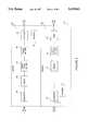
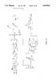
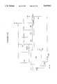
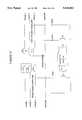
- FIG. 1is a block diagram of a cable television/video distribution and selection system in accordance with the present invention.
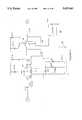
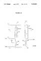
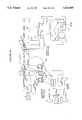
- FIG. 2is an exemplary schematic block diagram of a power line video coupler, comprising a transmitter section and a receiver section in accordance with the present invention.
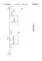
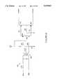
- FIG. 3is a schematic diagram of a transmitter amplifier circuit 58 shown in FIG. 2.
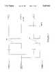
- FIG. 4is a schematic diagram of transmitter 15 mixer 60 shown in FIG. 2.
- FIG. 5is a schematic diagram of transmitter band pass filter 64 shown in FIG. 2.
- FIG. 6is a schematic diagram of transmitter 66 shown in FIG. 2.
- FIG. 7is a schematic diagram of couplers 68 and 70 shown in FIG. 2.
- FIG. 8is a schematic diagram of receiver mixer 72 shown in FIG. 2.
- FIG. 9is a schematic diagram of receiver band pass filter 108 shown in FIG. 8.
- FIG. 10is a schematic diagram of receiver elliptic band pass filter 76 shown in FIG. 2.
- FIG. 11is a schematic diagram of automatic gain control amplifier 80 shown in FIG. 2.
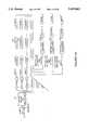
- FIG. 12is a block diagram describing the video receiver in the improved embodiment.
- FIG. 13is a schematic diagram of an improved receiver interface illustrating a multi-pass band power line coupler.
- FIG. 14is a schematic diagram of a power line video line receiver output automatic gain control.
- FIG. 15power line coupled video receiver attenuator circuit.
- FIG. 16is a block diagram of a power line coupled video transmitter.
- FIG. 17is a schematic diagram of a power line coupled video transmitter depicting the AC line driver circuit.
- FIG. 18is a schematic diagram of a power line coupled video transmitter AGC and mixing circuit.
- FIG. 19is a schematic diagram depicting a power line coupled video transmitter mixing and amplification circuit.
- FIG. 20is a schematic diagram of an AC power line coupled infrared remote control receiver.
- FIG. 21is a schematic diagram illustrating the AC power line coupled infrared transducer.
- FIGS. 22 and 23schematically represent traditional duplexing couplers on both low and high voltage power lines.
- FIG. 24illustrates the frequency characteristics of traditional serial LC couplers.
- FIG. 25schematically represents the general circuit diagram of the phase shift linear coupler of the present invention.
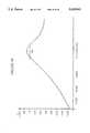
- FIG. 26illustrates the frequency characteristics of the phase shift linear coupler of the present invention.
- FIG. 27is a block diagram of a power-line communication apparatus in accordance with the present invention.
- FIG. 27Ais a block diagram of a power-line communication apparatus in accordance with the present invention including power-line transformers.
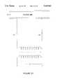
- FIG. 28is a schematic diagram of first coupling means in accordance with the present invention, which corresponds to the coupling TA-RB shown in FIGS. 27 and 27A.
- FIG. 29is a schematic diagram of second coupling means in accordance with the present invention, which corresponds to the coupling TB-RA shown in FIGS. 27 and 27A.
- FIGS. 30A and 30Billustrate the coaxially extended air-core transformer with coupling capacitor utilized in the present invention.
- FIG. 30Cillustrates a half duplexing coupler in accordance with the present invention for data communications through distribution transformers.
- FIG. 31Ais a schematic diagram corresponding to the modulator FA/demodulator FB shown in FIG. 27.
- FIG. 31Bis a schematic diagram of an alternative modulator FA/demodulator FB for the system in FIG. 27.
- FIG. 31Cis an FSK decoder phase lock loop which can function as the modulator/demodulator circuit of FIG. 27.
- FIG. 31Dis the primary phase lock loop of FIG. 31A;
- FIG. 32is a schematic diagram of a transmitter means used in the present invention.
- FIG. 33is a schematic diagram of receiver means used in conjunction with the transmitter means shown in FIG. 32, in the power-line communication of data signals over long distances.
- FIG. 33Ais a schematic diagram of a receiver which can be used for high speed communications.
- FIG. 34is a schematic representation of a coupling for the power line from phase to ground.
- FIG. 35is a schematic representation of a three phase coupling to the power line, three phases to ground.
- FIG. 36illustrates a two phase coupling connection to the power line, phase to phase.
- FIG. 37shows a three phase transformer coupling of the type predominantly used in Europe.
- FIG. 38shows a one phase transformer coupling of the type generally used in the United States.
- FIGS. 39 and 39Ashow a spread spectrum transmitter/receiver in accordance with the present invention which is particularly applicable for communication in between noise.
- FIG. 40phase shift keying modulator/demodulator which can be utilized with the present invention.
- FIG. 41is an equivalent circuit model for a power-line carrier communication system with resistive matching to the power line characteristic impedance by the coupler.
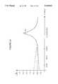
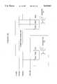
- FIG. 42is a graph of power line attenuation versus carrier frequency on the 35 KVAC power line for a 20 KM distance.
- FIG. 43is an illustration of an electric meter reading system incorporating the communication system of the present invention which may be implemented by a public utility.
- FIG. 43Ais a block diagram illustrating the use of the couplers of the present invention within a LAN linked by power lines or conventional phone lines.
- FIG. 44is a block diagram of the system of FIG. 42 as applied to a multiplicity of substations.
- FIG. 45is a simplified block diagram of the system of FIG. 40.
- FIG. 46is a block diagram of a power line communication system.
- FIG. 47is an equivalent circuit model for a power-line carrier communication system with resistive matching to the power line characteristic impedance by the coupler.
- Power line coupling technologyhas been the subject of U.S. patent application Ser. No. 08/270,002 filed Jul. 1, 1994, and European Patent No. EP90-907-855.2. The following extended explanation reviews power line coupling technology as described and as necessary to practice the video distribution system disclosed herewith.
- Power-line carriersare well known in the field of power system communications.
- the principal elements of such power-line carriersare transmitting and receiving terminals, which include one or more line traps, one or more coupling capacitors, as well as tuning and coupling equipment.
- Detailed information regarding the description and typical composition of conventional power line carriersmay be found in Fundamentals Handbook of Electrical and Computer Engineering, Volume II: Communication, Control, Devices, and Systems, John Wiley & Sons, 1983, pp 617-627, the contents of which are incorporated herein by reference.
- a significant problem associated with prior art power-line carriersis their requirement for one or more line traps, one or more capacitors, one or more coupling transformers or one or more carrier frequency hybrid circuits and frequency connection cables.
- the new power-line carrier systempresents a solution to the fundamental problem of matching the electrical line characteristic impedance with the line coupler.
- the novel signal coupler designis easily adaptable for operation on distribution and low voltage lines.
- All traditional couplersincorporate a ferrite or iron core transformer which causes signal distortion due to the non-linear phase characteristic of the transfer function between the transmit coupler and the receive coupler.
- the distortionis created by the presence of magnetic core material which exhibits hysteresis.
- the distortionis particularly severe because the signal must propagate through three such non-linear devices, the distribution transformer and two power-line couplers, that use ferrite core transformers.
- the distortionleads to envelope delay distortion which limits communication speeds.
- a line with characteristic impedance Zois ideally matched by terminations equal to Zo at both ends. Since Zo is primarily resistive at the frequencies of interest, the input impedance of the couplers should also be primarily resistive and equal to Zo at the carrier frequencies.
- FIG. 25A general configuration to achieve this is shown in FIG. 25. It uses a serially connected equivalent capacitor, Ceq. on the primary off a transformer. The design is based on two principles. First, the resonance between the coupling capacitor, Ceq and the primary winding inductance, L1, provides a low resistive impedance at the desired transmit carrier frequency. Second, Ceq has a large enough impedance at 60 Hz to block the line frequency. Note that this approach is not new, however, previous efforts at achieving satisfactory impedance matching encountered problems discussed below.
- the present inventioncharacterized in FIG. 35, has two coaxial solenoids or air-coils of different diameter with primary and secondary inductances L1 and L2 respectively. Both L1 and L2 are inductively and capacitively coupled creating an air-core transformer (see FIG. 30A).
- the air-gapis filled with resin which insulates the AC current from the transceiver.
- the size of the gapis selected to reduce inductive loading effects from coupler secondary to the primary. Since the coupling capacitor, Ceq, is significantly larger than the static capacitor, Cs the static capacitor (FIG. 41) does not mistune the desired carrier frequency. Inductive loading effects from the secondary to primary of the air-core transformer are minimized at the transmit frequency.
- the effective transceiver input independence, as seen at the primary,is equal to the resistance of the primary winding (Rt or Rr). This value can be chosen to optimally match the line characteristic independence.
- Zoequals the resistance of the primary winding, Rt, of the air-core transformer about 25% of the source power can be coupled into the line through the power line coupler.
- Zovaries between 5 and 150 Ohms on distribution lines and 1 and 20 Ohms on 120/240 V network lines depending on loading conditions. Since insertion loss increases rapidly for termination impedances were the primary winding impedance is greater than Zo (as compared to primary winding impedance less than Zo), a prudent design choice is to use a value of primary winding resistance approximately equal to the minimum value of the line characteristic impedance, Zo.
- a significant reduction of 60 Hz harmonicsare observed at the secondary side of the novel coupler. This reduction can exceed 20 dB over a wide band.
- Most noise generated on power lines by AC motors and equipmenthas a large reactive source impedance. This type of noise experiences significant loss through the novel couplers due to the coupler's low resistive impedance at or around the carrier frequency of the transmission or reception.
- the transfer characteristic of ferrite or iron core couplerstypically has a high Q (FIG. 24), which is advantageous in theory for reducing the effects of the harmonics outside the bandwidth, but in actuality constrains the useful transmission bandwidth of the power-line carrier and does not provide noise attenuation inside the bandwidth.
- the wide bandwidth noise rejection of the novel couplerobviates the need for a sinx/x type receive filter for harmonic rejection. This implies that no separate receiver is required, other than the coupler, for high speed transmission.
- phase linearity achievedAnother significant aspect of the design is the phase linearity achieved.
- the matching of the line impedance and the use of air-core transformersare responsible for the amount of phase linearity achieved.
- the phase response of the overall transmission systemis linear over a very wide range of frequencies. This implies that almost any desired frequency range can be selected for communication.
- standing wavesare virtually suppressed due to the low resistive matching at both ends of the line.
- the peak amplitude of the first reflectionis around 40 mV, which is small compared to the transmitted signal amplitude of a few volts.
- setting the receiver threshold above 40 mVcan eliminate any remaining source errors.
- the best frequency range 120/240 V power linesis 70-160 KHz (this includes LAN operations).
- the optimal frequency to useis the 25-45 KHz band.
- a frequency range of 70-480 KHzis appropriate.
- the novel coupler of the present inventionis equally applicable to any voltage AC, DC, phone, twisted pair or coaxial line.
- FIGS. 27 and 27Ablock diagrams of a power line communication apparatus 10 according to the present invention for use in low power applications (up to 480 VAC).
- the communications apparatus 10 shownis coupled to a pair of power lines 312, and generally comprises first coupling means 314, first transmitter means 316, first receiver means 318, and first modulator/demodulator means 320 at a first location along the power lines 312.
- the combination of transmitter means 316, receiver means 318 and modulator/demodulator means 320comprise a first modem means 321.
- second coupling means 322second transmitter means 324 second receiver means 326 and second modulator-demodulator means 328.
- the combination of transmitter means 324, receiver means 326 and modulator/demodulator means 328comprise a second modem means 323.
- both coupling means 314, 322include a pair of serial LC circuits (FIGS. 28 and 29) which are coupled to the pair of power lines 312. Referring to FIG. 27A, the apparatus is coupled to power line transformers 327. Each of the serial LC circuits in a respective one of the coupling means 314, 322 resonate at a given frequency.
- the LC circuitsinclude a plurality of capacitors which are connected in a series and parallel configuration. See FIG. 25.
- the coupling means 314, 322further incorporates novel air-core transformers for both transmission and reception which serve as the inductive (L) component of the respective LC circuits. It is to be noted that while the present invention is being described in the context of two identical communications apparatus, either circuit may be configured to function as a simple receiver or transmitter.
- the first transmitter means 316coupled to the first coupling means 314, is capable of transmitting digital data signals carried by a first carrier frequency FA across the pair of power lines 312, and as shown in FIG. 27A, through power line transformers.
- the first receiver means 318coupled to the first coupling means 314, is capable of receiving digital data signals carried by a second carrier frequency FB from the pair of power lines 312.
- the modulator/demodulator means 320coupled between the first transmitter means 316 and the first receiver means 318, modulates the digital data signals to be carried by the first carrier frequency FA, and demodulates the digital data signals carried by the second carrier frequency FB.
- the second transmitter means 324is coupled to the second coupling means 322.
- Second transmitter means 324is capable of transmitting the digital data signals to be carried by the second carrier frequency FB across the pair of power-lines 312, and as shown in FIG. 27A through power-line transformers.
- the second receiver means 326is coupled to said second coupling means 322, and is capable of receiving the digital data signals carried by the first carrier frequency FA from the pair of power lines 312.
- the second modulator/demodulator 328coupled between the second transmitter means 324 and the second receiver means 326, modulates the digital data signals to be carried by the second carrier frequency FB and demodulates the digital data signals carried by the first carrier frequency FA.
- the first and second carrier frequencies FA, FBpreferably comprise frequencies up to 11 MHZ.
- the first and second carrier frequencies FA, FBwill typically comprise frequencies that are less than about 160 KHz, having bandwidths of less than 20 KHz.
- FA and FBWhen used for communication through power line transformers, FA and FB will typically comprise frequencies below 90 KHz (preferably 25-45 KHz) with bandwidth of about 6 KHz.
- the serial LC circuits (FIGS. 28 and 29) of both coupling means 314, 322each comprise resistive matching means which will be described in greater detail below.
- the coupling means 314(FIG. 28), 22 (FIG. 29) each include a pair of serial LC circuits 330, 332 which resonate at the carrier frequencies FA, FB.
- FAwill correspond to F1 and F2
- FEwill correspond to F3 and F4.
- the serial LC circuit 330 shown in FIG. 28resonates at the second carrier frequency FB
- serial LC circuit 332resonates at the first carrier frequency FA
- the serial LC circuit 330 of FIG. 29resonates at the first carrier frequency FA
- serial LC circuit 332resonates at the first carrier frequency FB.
- the LC circuitsinclude respective serially and parallel connected capacitor networks 334, 342. To each capacitor in series is connected a resistor 335 and 345 which evenly divides down the AC voltage.
- the resistor valuesshould be rated at 1 Megohm per 5 watts and the capacitors should be 200 VAC capacitors.
- the resistorsshould preferably be thick film (i.e. carbonless).
- the Q point of the capacitorsshould similarly be high.
- the couplers (LC)should be placed into a resin for good insulation when used with operating voltages up to 660 V. At operating voltages above 660 v, the capacitors should be separately placed in an oil filled insulator and the air coil transformer placed into a resin.
- the use of the resistors 335, 345serve to minimize the DC current so as to prevent spiking and afford lightning protection.
- capacitor networks 334, 342create equivalent capacitances Ceq1 and Ceq2 for transmission and reception, respectively.
- the capacitor networksare connected to air-core transformers to be discussed below which function as the inductive element (L) of the LC circuit.
- Ceq1 and Ceq2resonate with the primary windings of the air-core transformers.
- the air coil meanscomprise a first air coil 336 which includes a primary winding 338 and a smaller secondary, winding 340 situated coaxially within the primary winding.
- the second serial LC circuit 332includes second air coil 344 including a primary winding 346 and smaller secondary winding 348 situated coaxially within the primary winding.
- the first plurality of capacitors 334are connected together in series between one of the power lines 312 and the primary winding 338 of the first air coil 336.
- the primary winding 338 of the first air coil 336is thereafter serially connected to the other power line 312.
- the secondary winding 340 of the first air coil 336is connected to its respective transmitter means 316.
- the second plurality of capacitors 342are serially connected together between one of power lines 316 and the primary winding 346 of the second air coil 344.
- the primary winding 346 of the second air coil 344thereafter being serially connected to the other power line 312.
- resistors, 335 and 345function to evenly divide the voltage and serve to minimize spiking and afford lightning protection.
- the phase shift linear transformer of the present inventioninvolves a dielectric core coupler which uses a dielectric material disposed between the primary and secondary windings.
- a dielectricis a material which is an electric insulator or in which an electric field can be sustained with a minimum dissipation in power. Examples of other dielectric materials include plastic, paper, wood, resin compounds, glue based compounds, as well as other materials understood by those skilled in the art to be dielectric and suitable for the core of a transformer as described herein.
- a dielectricis used to insure that the AC voltages are not transferred from the primary winding to the secondary winding. Even the several hundred kilovolts which can be contained in a lightening strike which may hit the primary, would be insulated from the secondary by the use of a dielectric material such as a resin.
- an epoxy coreis used.
- the epoxy core of this embodimentis made up of a resin and an activator. It is desirable to minimize the shrinkage of the resin. For this reason, a medium shrinkage resin such as that contained in EP5342 of Eager Plastics Company, Chicago, Ill. can be used. Other suitable resins and activators (epoxies) will be understood by those skilled in the art. Multiple pours of the epoxy as well as fillers (such as slate, flour or sand) can be used to minimize shrinkage and the exothermic heat it generates.
- an air-core coupleris used.
- the air-core coupler of this embodimentis constructed by wrapping the secondary and primary windings around plastic tubes having a hollow section. The tube with the secondary winding is fitted within the tube wrapped with the primary winding.
- air-coil couplers or structuresare referred to throughout the specification, dielectric core, couplers or structures, such as resin core couplers, can be used interchangeably.
- the tube of the phase shift linear transformer over which the primary winding is wound and within which the dielectric material is filledcan be made of a plastic or similar dielectric material as recited above.
- the tube/dielectric material combinationcan be a single piece forming a solid bar of dielectric material such as a medium-shrinkage resin.
- the secondary windingis then wrapped around this dielectric bar and then the dielectric bar with the secondary winding is enveloped in a casing of a dielectric material such as the low-shrinkage resin over which the secondary is wound or another dielectric material such as a plastic.
- the primary windingis then wound around the secondary dielectric material encasing the secondary winding.
- Both the primary and secondary windings in a preferred embodimentare wound very tightly, so that the insulation from one wire abuts the insulation of an adjacent wire. Therefore, the distance between adjacent wires is the thickness of the insulation on each adjacent wire.
- the particular gauge wire as well as the diameter of the overall windingdepends upon the frequency for which the particular phase shift linear transformer is being designed.
- Example wirecan be between 320 and 336 gauge for the many applications although higher or lower gauge wires can be used depending upon the particular application.
- the primary and secondary windingsmay have different gauge wires used again to tune the device to the particular frequency for a specific application. It is also possible for a particular application that the primary and the secondary would use the exact same wire for their windings.
- Examples of wires which can be used for the primary or secondary windingare copper/magnet wires such as Belden Heavy Armored Poly-Thermaleze and single Beldsol® Solderable wires of Belden Wire and Cable. Other wires suitable for the primary and secondary windings will be understood by those skilled in the art.
- both the primary and secondaryare single layer windings, not multiple layer windings. Also, in a preferred embodiment, both the primary and secondary windings are adhered to the resin or resin tube.
- One method for adhering the wire to the dielectric tube or dielectric baris through the use of a glue.
- FIG. 30Aillustrates the transmitter transformer 336 with coupling capacitor network Ceq1.
- the transmitter transformer 336is connected in series with Ceq1 and the power line 312.
- the transformeris phase shift linear and comprises a primary winding 338 and coaxial smaller secondary winding 340 which is placed between the primary winding.
- the primary winding 338has a winding diameter 2R 339 which is greater than the diameter of the secondary winding 2R 41 and accordingly creates an air gap between the two.
- both the primary and secondary windings 338, 340 in the transmitter air coilshave the same number of turns (designated by N1-N2), and are thus at a 1:1 ratio. Accordingly, the transmitter doesn't require a high transmission voltage, as is characterized by prior art devices. Further Ceq1 is set to resonate with the primary winding at the carrier frequency FA, thus creating a band pass filter at the carrier frequency FA. This maximizes the current at the carrier frequency FA.
- the values of Ceq1 and the resistors, 335, 345are set to generate a large voltage loss at frequencies less that 10 KHz (thus encompassing the 60 Hz and its harmonics).
- the significantly reduced 60 Hz signalcannot generate a large enough current to pass the static capacitance. That is, for transmission, the resistivity of the primary coil is roughly equal to the lowest known value of the characteristic impedance of the power line.
- the receiver transformeris now described with respect to FIG. 30B.
- the receiveris connected to the power line 312 via Ceq2.
- the receiver air coilcomprises a phase shift linear transformer having a primary winding 46 with a first diameter 2R 347 and a secondary coaxial winding 348 having a second diameter 2R 349. Accordingly, an air gap, and thus a static capacitance, is similarly created between the respective primary and secondary windings 346, 348.
- the ratio of the primary and secondary windingscan be about 1:1. While this ratio can be altered or modified, such a change requires a resultant alternation in the size of the air gap, i.e. the relative ratio of 2R and 2r.
- the capacitor network Ceq2is set to resonate with the primary winding at carrier frequency FB, thus creating a band pass filter at carrier frequency FB.
- the power line voltageis significantly reduced by Ceq2 and the resistors.
- the static capacitance with the secondary windingsignificantly attenuates the 60 Hz and its harmonics, thus effectively functioning as a high pass filter.
- the carrier frequency voltageis thereby maximized.
- the air-core transformerproduces a wider phase linear bandwidth than previous systems.
- the bandwidth characteristics off the present inventionare shown in FIG. 26.
- the resistivity off the primarycan be equal or greater than the lowest characteristic impedance of the power line.
- Ceq1should have a smaller value:
- (f)2(carrier)/(f)2(60 Hz) ratiodetermines the Vcarrier/V60 Hz ratio at the output of the coupler.
- a higher carrier frequencyshould be used for higher power line voltages.
- Vcarrieris measured at the preselected carrier frequency at the secondary output of the receiver coupler in volts.
- V60 hz measured at the same location of Vcarrier,is the voltage of the 60 Hz.
- the above relationships coupled with the capacitive transformersserve to block the 60 Hz line current.
- the resistive matchingserves to reduce power line noise at the bandwidth.
- the abovemakes it possible to communicate directly through power line transformers.
- the use of an air-core transformerreduces reflected impedances from the secondary side as well as from the power line transformer to the primary side of the air-core transformer.
- FIG. 47shows a power line communications system for matching the characteristic impedance of an electrical line using an air-core (or dielectric) coupler (or transformer) which is capacitively and inductively coupled to the electrical line.
- Zois the characteristic impedance of the electrical line where Zo is approximately equal to the square root of L/C and L and C are the inductive and capacitive components, respectively, of the electrical line.
- Ceq and L1are the equivalent capacitance and the inductive component of the Primary of the air-core coupler.
- R1is the resistive value of L1
- L2is the inductive component of the secondary of the air-core coupler.
- R2is the resistive value of L1.
- Rintis the impedance of the transmitter or the input impedance of the receiver, depending upon whether the air-core coupler is operating as a transmitter or receiver.
- FIG. 47illustrates the air-core coupler of the present invention working either as a transmitter or a receiver (or transceiver).
- the air-core coupler primary windingis matched to the electrical line characteristic impedance at a preselected frequency band, as well as to the other couplers attached to the electrical line at the same frequency.
- the secondary windingis matched to the transceiver (transmitter and/or receiver) input impedance. Since the values of L1 and Ceq approach zero at the preselected frequency F1, where F1 is given by equation (1). ##EQU1## (where F1, L1 and C1 are approximately zero), R1 (and the rest of the R1 values for any other couplers) will match Zo and ⁇ L2 will match Rint if standard copper magnetic wire is used for the primary and secondary windings.
- a resistance wiresuch as Deltalloy wire having a specific resistivity of 675 OHM CIR. MIL. FT. with a composition of 15% Chromium and 60% nickel, available from Delta/PWF Corp.
- R2can be increased and a wider bandwidth can be achieved.
- a preferred resistance wirehas a light magnetic attraction of approximately 5-10 ohms per foot for #24-434 gage wire (for example, 8.25 ohms per foot for #30 gage wire) which is coated/insulated.
- the coupling means 314, 322 shown in FIGS. 27, 28, 29, 30A and 30Bare suitable for communication in association with wide range of power line voltages. As will be discussed herein, they can be utilized for high voltage, low voltage, twisted pair, coaxial, and phone line communications, as well as for communication directly through power line transformers.
- the couplers of the present inventioncan be applied to LAN (local area network) communications and facilitate communication speeds up to 10 Kilobaud.
- the coupling means 314preferably use a first carrier frequency FA of around 75 KHz (and 81.5 KHz for FSK) and a second carrier frequency FB of around 111 KHz (and 117.5 KHz for FSK) over power lines 312 of up to about 1 KVAC.
- the couplerpreferably uses first pluralities of capacitors 334 as shown therein, the coupling capacitor equivalent circuit is equal to 90 nanofarads.
- the first air coil 336should have a primary winding 338 with a coil diameter of 2.2 cm, #26 gauge magnet wire and a secondary winding 340 with a coil diameter of about 1.7 cm, #28 gauge magnet wire.
- the second plurality of capacitors 342has an equivalent circuit equal to 15 nanofarads.
- the second plurality of capacitors 342has an equivalent circuit equal to 15 nanofarads.
- the second air coil 344should have a primary winding 346 of 2.2 cm, #30 gauge magnet wire and a secondary winding 348 with a coil diameter of about 1.7 cm, #28 gauge magnet wire.
- the systemutilizes the modems shown in FIG. 31A, 32 and 33A. Using a suitable transistor for transmitting, the communication speed can be increased above 9.6 kbaud over power, twisted pair, and coaxial lines.
- coupling means 322comprises first plurality of capacitors 334 as shown therein, the coupling capacitor equivalent circuit is equal to 40 nanofarads (this includes the static capacitance of the air-core transformer).
- the first air coil 336should have a primary winding 338 with a coil diameter of 2.2 cm, #26 gauge magnet wire and a secondary winding 340 with a coil diameter of 1.7 cm, #26 gauge magnet wire.
- the second plurality of capacitors 342, as shown therein, coupling capacitance equivalent circuitis equal to 33 nanofarads.
- the second air coil 344should similarly have a primary winding 346 of about 2.2 cm, #34 gauge magnet wire and a secondary winding 348 with a coil diameter of about 1.7 cm of the #30 gauge magnet wire.
- the resistive matching at the frequenciesshould be less than 1 Ohm for transmission and 3 Ohms for reception.
- the resistive matchingshould be about 1 Ohm for both transmission and reception.
- the couplersare also applicable to high voltage power line communication applications in which a 15 KVDC/4.5 KVAC capacitor can be used for power-line voltages of up to 765 KV.
- the couplers of the present inventioncan be utilized for communication speeds up to 9600 baud.
- first FA and second FB carrier frequenciesof 80 KHz and 115 KHz, respectively, are preferred, and the connections of first 334 and second 342 pluralities of capacitors are somewhat modified over what is shown in FIGS. 28 and 30.
- the first plurality 334comprises a 2 nanofarad coupling capacitor for 80 KHz transmission.
- the second plurality 342comprises a 0.5 nanofarad coupling capacitor for reception. It is to be appreciated that the above system will be comparatively large, having a height of approximately fifteen feet and will typically be located at a ground station adjacent to large high voltage transmission line.
- the first air coil 336 of the coupling means 314suitably comprises a primary winding 338 with a coil diameter of 8.9 cm, #24 gauge magnet wire, and a secondary winding 340 with a coil diameter of 6.0 cm of #16 gauge magnet wire.
- the second air coil 344likewise suitably comprises a primary winding 346 of 7.3 cm, #26 gauge magnet wire, and a secondary winding 348 with a coil diameter of 4.8 cm, #16 gauge magnet wire.
- the identical coupling means 322under the same circumstances also includes the capacitor pluralities 334, 342.
- the first plurality 334suitably comprises a 1 nanofarad coupling capacitor for transmission at 115 KHz
- the second plurality 342comprises a 1 nanofarad coupling capacitor for 80 KHz reception.
- the first air coil 336comprises a primary winding 338 with a coil diameter of 8.9 cm, 24 gauge magnet wire and a secondary winding 340 with air-coil diameter of 6.0 cm, #12 gauge magnet wire.
- the second air coil 344likewise suitably comprises a primary winding 346 of 8.9 cm, #26 gauge magnet wire and a 348 with a coil diameter of about 6.0 cm, #16 gauge magnet wire. No ferrite transformer is found within the transmitter and receiver. It is also possible that no receiver is needed.
- the resistive matching for transmissionis about 5 Ohms and for reception is about 10 Ohms for duplexing operations. A resistive match of approximately 5 Ohm is needed for half duplexing operation where transmission and
- FIG. 42is a graph of power line attenuation versus carrier frequencies on the 35 KVAC power line for 20 KM distances. A 150 Ohm load was used for the matching conditions. The best range of communication can be seen here from 70 to 160 KHz. As the number of transformers on the power line increases, the attenuation of the power line will increase especially above 100 KHz. Note that the diameter of the coils is partially determined by the available size of the PVC pipe because the windings are made on said pipe.
- the communication apparatus of the present inventionmay also be utilized for communication through power line transformers (See FIG. 43) .
- FIG. 30Cillustrates a half-duplex coupler for data communication through the high voltage side of distribution transformers.
- two or three solenoids (air-coils)having two or three different diameters are utilized.
- the diameter of outer coil 354is 6.0 cm, #26 gauge magnet wire, the middle 356 is 4-8 cm, #20 gauge magnet wire and the smallest 358 is 4.2 cm, #22 gauge magnet wire.
- the largest diameter outer coil 354is the primary which resonates with the capacitor, the middle is the transmitter and/or receiver coil 356 and the smallest is the receiver coil 358 (if it is needed). For reception, the transmitter coil must be uncoupled. In order to have transmission, the receiver coil is uncoupled.
- the systemcan be configured to use the same carrier frequency, with one coupler on the low voltage side (i.e. a single primary and single secondary) . (See FIG. 43) .
- the transformeris coupled to 66 nanofarad capacitors-500 VAC) -In this situation, the primary coil 338 has a diameter of 2.7 cm using #24 gauge magnet wire with the secondary coil 340 having a diameter of 2.2 cm using #26 gauge magnet wire.
- the transmitter and receiverdo not contain a ferrite transformer. It is also possible that no receiver will be needed.
- a real time 4800 baudcan be achieved through power line transformers over long distances. It is to be appreciated that the couplers of the present invention will permit more than one carrier frequency to be simultaneously transmitted through the same power line.
- the preferred transmitter 316, 324 useful in the power line communication of data signals over long distancesis shown in FIG. 32.
- This transmittercan be utilized in all of the applications of the present invention, including transmission through power line transformers.
- the transmitter meansgenerally comprises a driver 362 which is connected to the coupling means 314, 322 by way of their respective connections TFA/B1, TFA/B2. Because of its use of a magnetic coil 364 and transistors 366, 368, the transmitter 316 while comparatively slow, is especially useful over high voltage power lines.
- Suitable transistors 366 for this transmitterare conventional SK 3444, while the transistors 368 may suitably comprise conventional SK3024. For higher power transmission, 2N3055 transistors may be utilized instead of SK3024.
- each resistor and capacitor shown in FIG. 32will depend upon the specific operating characteristics of the driver but they would be readily ascertainable without undue experimentation by one of ordinary skill in the art of electronics. Nevertheless, exemplary values of the resistors and capacitors are shown in FIG. 32. It is also understood that without a ferrite transformer, this modified transmitter is able to transmit at a high communication speed.
- the preferred receiver means 318, 326which is useful in the power line communications of data signals over long distances is shown in FIG. 33.
- the receiver means 318, 326is similarly connected to the coupling means 314, 322 by way of their respective connections RFA/B, RFA/BGND and RFA/BC. It will be readily apparent that the receiver means 318, 326 is more successful at attenuating out of band noise especially on high voltage power lines.
- Suitable transistors 366are also conventional SK3444.
- the particular value for each resistor and capacitor shown in FIG. 33would depend upon specific operating characteristics off the receiver 318, but they would be readily ascertainable without undue experimentation by one of ordinary skill in the art off electronics. Nevertheless, exemplary values off the resistors and capacitors are shown in FIG. 33.
- a key feature off the receiver off FIG. 33is the inclusion of potentiometer 375 with which the bandpass filter receiver bandwidth can be changed.
- Another featureis the notch filter 379 coupled to magnetic coil 364 (band pass filter)
- FIG. 33Ashows an additional receiver 318', 326' which can be utilized between 120 V and 240 V including FSK, and which is particularly suited for low voltage LAN communications.
- C1 and R1are used for F1; and C3 and R2 are used for F2 in a high pass configuration.
- C2 and L1are used for F1 and C4 and L1 are used for F2.
- the receiverfurther utilizes a notch filter 383 coupled to band pass filter 385 which filters out transmission frequencies. It is also appreciated that using no receiver or a modified receiver which does not contain a ferrite transformer the communication speed can be significantly increased.
- FIGS. 31Aillustrates an FM modulator and demodulator 320.
- This circuitis particularly applicable for high voltage communication and particularly high voltage communication through power line transformers.
- the circuitcomprises an XR-2211 FSK demodulator 397 XR-2207 FSK generator 399 and MAX232 computer input/output interface 401.
- the values for R0, C0, C1, C2, C3 and C4are utilized to alter the carrier frequencies (FA and FB) .
- the values of C1, R3 and R4are varied to alter the FA and FB carrier frequencies.
- FIG. 31Billustrates an alternative FM modulator and demodulator 320' for high frequency communication for LAN and phone line communication.
- the circuitincorporates the XR-210 FSK demodulator 403, XR-2207 FSK generator 405 and MAX232 computer input/output interface 407.
- the values for R0, C0, C1, C2, C3 and C4are utilized to alter the carrier frequencies (FA and FB).
- the values of C1, R3 and R4are varied to alter the FA and FB carrier frequencies.
- FIGS. 31C and 31Dillustrate additional modulator/demodulator circuits 320', 320'" which can be utilized in the present invention.
- FIG. 31Cshows an FSK decoder using the 565 interface 409. The loop filter capacitor is chosen to set the proper overshoot on the output and a three-stage RC ladder filter is used to remove the noise frequency component.
- FIG. 31Danother FSK chip, the XR2211 411 can be used to demodulate and the XR2207 (not shown) can be used for modulation.
- FIGS. 39 and 40illustrate two complete modem configurations which can be utilized in the present invention.
- FIG. 39is a spread spectrum transmission and receiver modem. This circuit is suited for communication through high voltage AC and DC power lines and for communication through transformers. The spread spectrum modem can be used for error free communication over long distances.
- FIG. 40illustrates a phase shift keying transceiver modem circuit particularly applicable for phone line and LAN communication.
- This circuitincludes an XR2123 modulator/demodulator 433, XR2208 Operation Multiplier 415, and DM74193 synchronous up/down counter 417.
- This circuitrequires a smaller bandwidth for communication than FSK because it uses only one carrier frequency while changing sine and cosine waves.
- the carrier frequencymust always be at least 10 dB above the noise.
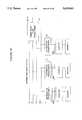
- FIGS. 43-46The particular attributes of the apparatus and configurations of the present invention are perhaps best illustrated in view of the following comprehensive example described with reference to FIGS. 43-46.
- This exampleutilizes most of the coupler configurations and modems discussed above and illustrates how the communications apparatus and novel couplers of the present invention can be utilized in a comprehensive system using LAN, phone line, high voltage and low voltage power line communications, as well as communication through power line transformers.
- FIG. 43illustrates an example of the couplers of the present invention as they may be utilized by an electric power public utility for reading home power meters.
- each house 419 receiving electric power from utilitywould have a modem 421 and air coil transmitter and receiver coupler circuit 423 in accordance with the present invention coupled to the electricity meter 425.
- the coupler 323would connect to the 240 low volt distribution transformer 426, via low voltage lines, situated on the utility pole 427 located adjacent to the house 419.
- the couplerswill have the low voltage configuration which is capable of communicating through power line transformers such as discussed in section A.3. above.
- the systemwill utilize the transmitters, receivers, modulators/demodulators, or modem circuits disclosed in FIGS. 31A, 32 and 33.
- the distribution transformerwill be connected to one of the three 13.2 KV power lines 429 on the utility pole 427.
- a second substation modem 433is connected to one of three couplers 435 in accordance with the present invention.
- the couplersare encased in resin, as disclosed above, and will preferably have the high voltage side transformer configuration set for the in FIG. 30c.
- the substation 433is itself connected via couplers 437 such as disclosed in section A. 11 to the large central computer 439 of the utility (generally a VAX) via phone lines.
- the substation 431 and computer 439will communicate over the power or phone line at rates up to 10K baud as set forth herein using the high speed couplers and the appropriate high speed modems.
- the central computer 439When the utility desires to make a meter reading, the central computer 439 will issue an addressable command which is transmitted via a master modem 441 and coupler 437 to the particular substation at speeds up to 10K baud over power or conventional phone lines 438. The substation will then transmit an addressable command to a particular meter via modem and couplers. The command is transmitted over the 13.2 KV line at speeds up to 1200 baud, through the distribution transformer, through the home couplers 423 and modem 421. A meter reading is recorded, transmitted by the home modem 421 through couplers 423, through distribution transformer 426, over the 13.2 KV power line 429 to the appropriate substation coupler 435 and to the substation modem 433. The system only requires between one and ten watts for power transmission in both directions.
- the meter readingmay be transmitted via conventional phone lines 438 to the central computer 439.
- the high speed LAN couplers of the present inventioncould be used within the utility to connect local workstations to the central computer 439.
- a clerical worker situated at a work stationmay access the VAX computer through the power lines of the facility via modems and high speed LAN or phone line couplers of the present invention at data transmission speeds of up to 10 Kbaud.
- FIG. 44is a block diagram of an expanded system which may be utilized by a public utility to meter a multiplicity of substations.
- the central computerwould simultaneously read a large number of meters via a master modem and multiplexer coupled to a multiplicity of couplers 443.
- the computercommunicates with each substation (1, 2, 3, etc.) over conventional phone lines.
- the respective substationsthen communicate with the individual meters at 1200 baud via high voltage distribution line and through distribution transformers.
- FIG. 45is a simplified block diagram of the communication system of FIG. 43.
- FIG. 46is a block diagram of how the couplers of the present invention can be utilized to communicate through two power line transformers 445 and through a three phase large transformer 447.
- the couplerswill comprise low voltage couplers designed for communication through power line transformers as discussed above.
- the couplers of the present inventionwill permit the simultaneous transmission and reception of more than one carrier frequency through the couplers.
- the couplerscan be simultaneously utilized by an electric public utility for electric meter reading at a first frequency while a public water utility utilizes the couplers at a second carrier frequency for water meter reading.
- FIG. 34illustrates the general case of coupling the apparatus to the power line, phase to ground.
- the carrier frequencyis undetectable by other phase-ground coupling connections and each phase is isolated from each other for communication purposes.
- FIG. 35illustrates a special three phase coupling connection to the power line, 3 phases to ground. This system utilizes all three phases from the power line and ground for communication. In this case, the carrier frequency is detectable on any phase-ground coupling connection. In this manner, the phases are interconnected for communicating purposes.
- FIG. 36illustrates a special two phase coupling connection to the power line, phase to phase 447. This system utilizes two phases from the power line for communication. The carrier frequency is detectable only on the two phase coupling connection. In this configuration, only the coupled two phases are connected from communication purposes.
- FIG. 37illustrates a three phase transformer coupling around delta and Y (Wye) transformers 449. This coupling system is generally utilized in Europe. The carrier frequency is detectable on the other power line. In this manner, two different high voltage power lines are connected to each other for communication purposes.
- FIG. 38illustrates a one phase transformer coupling which is generally used in the U.S.A. In this manner, the carrier frequency is detectable on the other power line. Accordingly, two different high voltage power lines are connected to each other for communication purposes.
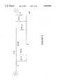
- FIG. 1a block diagram of an exemplary cable television and video distribution and selection system constructed in accordance with the present invention.
- System 10can be setup in any home or other building which is wired with AC electrical wiring, such as 3 strand (ground, hot, neutral) used in home and building construction.
- 3 strandground, hot, neutral
- System 10allows the operation of up to four simultaneously and independently operated television sets or other viewing or recording devices, such as a monitor or VCR.
- System 10is designed to operate using analog signals distributed throughout a home or building and thus, does not require more expensive digital to analog and analog to digital equipment necessary to make these conversions.
- Main cable 30carries cable television signals into a house or building (not shown).
- Main cable 30is a source for video signals which can be selected by televisions or other tuning devices distributed throughout the home or building.
- a VCR 31 or other video broadcast devicessuch as a laser disc player or a video camera can also serve as the video signal source or as an alternate video signal source for selection of signals by the tuning devices distributed throughout the home or building. Accordingly, the description which follows applies to the selection of a VCR 31 or other source device for video signals as well as the selection of cable television signals and can be incorporated into System 10.
- Cable 30is connected to distribution box 12, via lead lines 32.
- the present inventioncan distribute signals to four simultaneously and independently operating television sets or viewing/recording devices, four lead lines 32 connected to cable 30 are shown.
- Each lead line 32is connected to a separate channel selector (tuner) of distribution box 12.
- the channel selectors of the present inventioncan tune cable television channels as is understood by those skilled in the art.
- Selectors 1-4are correspondingly numbered--22, 24, 26, and 28. Further, each selector is connected to a corresponding power line video coupler (PLVC).
- PLVCs 1-4are correspondingly numbered 14, 16, 18, and 20. The selectors and power line video couplers operate in pairs as distribution devices.
- selectors and PLVCsmay be separate devices or a combined device (as illustrated in FIG. 2).
- channel selector 1 and PLVC 1operate together; channel selector 2 and PLVC 2 operate together; channel selector 3 and PLVC 3 operate together; and channel selector 4 and PLVC 4 operate together.
- each additional channel selector/PLVC pairwill be understood to operate in a similar fashion to the one being described.
- the difference between the four channel selector/PLVC pairs shown in distribution box 12is that each PLVC is tuned to operate at a different frequency band. This is to accommodate the four separate 6 MHZ video signals which can be transmitted between the 2 MHZ and 30 MHZ frequency band and which will be discussed more fully herein.
- Distribution box 12is connected to home electrical wiring 34 to distribute the cable television/video signals throughout a home or building.
- the connection between distribution box 12 and home electrical wiring 34will most commonly be made at a junction box or a fuse box (not shown), which in many instances will be located in proximity to the entry of cable 30 into a home or building.
- the cable and electrical entry points into a home or buildingare in a basement or garage.
- Distribution box 12may be of a size suitable for mounting on a wall near a fuse box or junction box and may be no more obtrusive than the fuse box or junction box. It is not necessary, however, for distribution box 12 to be located or connected to a junction box or fuse box.
- Distribution box 12can be located anywhere in a building where connection to electrical wiring 34 can be made and also access all rooms, via electrical wiring 34, where television sets are to be used. Such a location will also require access to source signals such as cable television or VCRs. If only VCR signals were being distributed (i.e., 4 VCR signals to choose from), proximity to a cable television connection 30 would not be required. It is also possible to set up system 10 so that a user could select a VCR signal or a cable television signal.
- connection between home electrical wiring 34 and distribution box 12is made at each PLVC.
- each PLVCis tuned to a different, overlapping, or interfering frequency, a single connection can be made from distribution box 12 to electrical wiring 34, as long as each PLVC is tied into this connection.
- a television set or other viewing or recording devicecan be placed in every room of a home or building or multiple television sets or tunable devices can be placed in every room. In the present system, however, only four can be operated independently (i.e., tuned to an independent channel) and simultaneously.
- Each televisionis connected to a remote device (receiver/selector) 36, 38, 40, and 43, respectively.
- Each remote devicecontains a PLVC which corresponds in number to the PLVC contained in distribution box 12 with the same PLVC numbering. This represents that each of the four PLVC units is correspondingly tuned to the same frequency as the PLVC unit contained in distribution box 12.
- a means for selecting a cable television channelor alternatively, a separate source such as VCR 31.
- An example of such a selection systemis a remote control cable selector box as is commonly provided by cable television service providers.
- remote control 53which operates in the infrared spectrum as is commonly used in cable television selectors, VCRs, televisions, stereo equipment, and video cameras, and is therefore understood by those skilled in the art.
- a separate remote control device, such as remote control 53would operate each selector section 37, 39, 41, and 43 of the corresponding remote devices, 36, 38, 40, and 42.
- a key pad entry located on a remote devicecould be used in addition or instead of remote control 53.
- a user desiring to watch a particular cable television channelwould use a remote control device 53, and pointing the device at a remote device such as remote device 36, select a channel.
- Remote device 36receives the infra-red signal from remote control device 53 at its selector 37.
- the selection signal(the channel selected) is then transmitted through PLVC 14 over home electrical wiring 34 to the corresponding PLVC 14 in distribution box 12.
- PLVC 14communicates this signal to selector 22 which tunes the requested cable channel from cable 30.
- the cable channel tuned by selector 22is then communicated through PLVC 14 in distribution box 12 through home electrical wiring 34 and back to remote device 36.
- the cable channel signalis then communicated through PLVC 14 located in remote device 36 to television set 44 for viewing by the user.
- a similar operationcan take place for television sets 46, 48, and 50 simultaneous with the operation described for television 44.
- a VCR 52can also be disposed between a remote device box and a television as is shown with respect to remote device 42 and television SO. This is a common setup when standard cable television boxes are used with VCRs and televisions.
- System 10will operate transparent to the user. The user will not recognize any difference between the operation of System 10 and a current cable distribution system. A difference in performance and operation will be the availability of a cable television outlet wherever an electrical outlet is located in a home, as every electrical outlet will also serve as a cable television outlet. Also, the possibility of having an alternate source signal such as VCR 31 will now be possible and selectable. With the increasing number of smaller and better quality televisions, the ability to connect a television set at any location in the house where an electrical outlet is located will be highly advantageous. Also, a VCR or other video signal source can be located any where there is an electrical outlet. It is not required by the present system that distribution devices be centrally located.
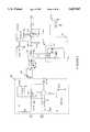
- FIG. 2a block diagram of a power line video coupler used in the present invention.
- Power line video coupler 14 shown in FIG. 2should be understood to be identical to PLVC 16, 18, and 20, except that each of the four power line video couplers is tuned to a different frequency band between 2 MHZ and 30 MHZ which are non-overlapping and do not interfere with each other.
- PLVC 14is shown divided into a transmitter section 54 and receiver section 56. Whether located in a remote device (with a television set) or in distribution box 12, each PLVC is required to both transmit and receive signals. When located in a remote device (connected to a television set), a PLVC will have to transmit a selector signal to select a cable television station. It will then be required to receive the corresponding cable television signal transmission. When located in a distribution box 12, each PLVC will be required to receive the selection signal for a particular cable television channel and then transmit the corresponding cable television signal.
- transmit section 54must take its input either from selector 22 in distribution box 12 or selector 37 in remote device 36.
- a cable television signalwill be provided by selector 22. This signal is fed into amplifier 58 and then into mixer 60.
- a frequency signal produced by oscillator 62 of mixer 60is combined with the input signal from selector 22.
- the mixed signalis then sent through a band pass filter 64 to filter out the component of the signal from mixer 60 which is not desired, allowing the cable television signal to pass through.
- the filtered signalis then sent through transmitter 66 and out through coupler 68 to the home electrical wiring 34.
- Coupler 68contains a pair of power line couplers as described earlier.
- a transmitter power supply 67is also shown in FIG. 2.
- Coupler 70When receiving a signal, the signal comes in through home electrical wiring 34 into a (pair of) coupler 70 which is located in receiver section 56 of PLVC 14. Coupler 70 is identical to coupler 68, but operates as a receiver instead of a transmitter and has a power supply 71. The signal then goes through mixer 72 which operates in, an opposite manner to the operation of mixer 60. This will "unmix” the down-converted signal, restoring it to its original frequency. The unmixed signal then leaves mixer 72 and enters an elliptic band pass filter 76. The filtered signal is then put through an automatic gain control 80 to optimize this signal which is then output to television set 44.
- the selector/receivers of the present inventionare designed to transmit signals in the frequency range between 60 and 72 megahertz when sending a signal between a remote device and a television set.
- VHF channel 3corresponds to the frequency range of 60-66 megahertz
- channel 4corresponds to the frequency range of 66-72 megahertz.
- a userselects Channel 3 or 4 to eliminate interference as is commonly done when connecting a VCR to a television set.
- the present systemis designed to transmit over a house or building electrical power lines in a frequency range between 2 and 30 megahertz.
- the video signal with a 6 megahertz bandwidth(between 60-66 megahertz for channel 3 and 66-72 megahertz for channel 4) is down-converted to a signal with a bandwidth between 2 and 30 megahertz for video signal transmission.
- a 6 megahertz bandwidthis necessary for video transmission in analog format. Accordingly, there is a range of 28 megahertz in which 6 megahertz signals can be transmitted. Accordingly, this allows up to four separate transmission bands to be used without interfering with each other.
- Thisis the number of independently and simultaneously television sets or viewing or recording devices which can operate in accordance with the present invention and is illustrated as such in FIG. 1.
- a 6 megahertz bandwidthFor each separate television, a 6 megahertz bandwidth must be set aside. For example, beginning at 2 megahertz, adding 6 megahertz to this reserves the band between 2 and 8 megahertz.
- the selector signal sent from the remote devicerequires its "own" frequency so as not to interfere with the video signal transmission. Therefore, an extra four, single megahertz frequencies must be set aside to transmit the selector signal. Smaller or larger frequency bands could also be used, with a one megahertz frequency band described herein as an example.
- frequency bandsAn example allocation of frequency bands is to use the 2-6 MHZ frequencies as the four selector signal frequencies and begin the video signal (6 MHZ bandwidth) at 6 MHZ. Another way of allocating frequency bands is to add the one MHZ selector signal to the six MHZ video signal, yielding a frequency bandwidth of seven MHZ. The first or last portion of this seven MHZ frequency band could be used for the selector signal. Other ways of allocating frequency bands should be understood by those skilled in the art.
- the first video signal(i.e., first television) extends between 6 and 12 megahertz.
- the second signal(i.e., the second television) extends between 12 and 18 megahertz.
- the third signal(i.e., the third television) extends between 18 and 24 megahertz, and the fourth (i.e., the fourth television) extends between 24 and 30 megahertz.
- Each PLVC unitis designed to down-convert for transmission and up-convert for reception in one of these four band widths.
- PLVC 14for example, will be designed to operate in a first bandwidth between 6 and 12 megahertz.
- mixer 60 and mixer 70 in PLVC 14are designed to down-convert and up-convert the signal so that the signal sent through home electrical line 34 is in the 6 to 12 megahertz range. If channel 3 (between 60-66 megahertz) is used, it is necessary to generate a mixing signal of 54 megahertz. This 54 megahertz signal is generated by oscillators 62 and 74. By mixing in a signal of 54 megahertz, the 6 megahertz signal sits between 6 megahertz and 12 megahertz.
- mixers 60 and 72have to mix in a signal of 60 megahertz.
- oscillators 62 and 74provide a different signal to mixers 60 and 72 respectively, depending upon whether channel 3 or channel 4 was chosen by the user.
- Mixtures 60 and 72actually mix both the positive and negative component of the wave form generated by oscillator 62 and 74. As the signal is down-converted for transmission through electrical lines 34, it is necessary to filter out the unwanted (additive) portion of the wave form.
- Band pass filter 64only allows signals in the 2-30 megahertz band to pass.
- Elliptic band pass filter 76 in receiver 56carries out a similar function.
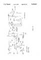
- FIG. 3There is shown in FIG. 3 a schematic diagram of amplifier circuit 58.
- Amplifier circuit 58provides an amplified signal to mixer 60.
- Amplifier circuit 58contains an amplifier 57 which is part No. AD 811, made by Analog devices.
- Transmitter mixer 60receives its input from amplifier 58.
- a signal (difference signal) from oscillator 62is generated within transmitter mixer 60 and is combined with the signal from electrical line 34 at mixer 80.
- An example of mixer 80is integrated circuit No. NE 612 made by Phillips. The down-converted signal passes through inductor 84 and then through amplifier 86 before being transmitted to band pass filter 64.
- Oscillators 62 or 74could alternatively be designed with adjustable LC circuitry to adjust the frequency needed to be generated by the oscillator circuit.
- Band pass filter 64is designed to pass signals in the 2-30 megahertz frequency and will be understood by those skilled in the art.
- FIG. 6There is shown in FIG. 6 a schematic diagram for transmitter 66.
- the input signal from band pass filter 64enters transmitter 66, it is amplified at amplifier 94, Part No. AD 811 made by Analog Devices.
- amplifier 94Part No. AD 811 made by Analog Devices.
- the couplers 68 used in an exemplary embodiment of the present inventionwill transmit a signal with a bandwidth of up to 3 megahertz, two 3 megahertz components must be generated for output.
- Buffers 96 and 98, Part No. EL 2008 made by Elantecare used to separate out two three megahertz components of the six megahertz video signal.
- output "A” from buffer 96would carry 3 megahertz of that signal (i.e., 6 to 9 megahertz) while output “B” from buffer 98 would carry the other 3 megahertz of that signal (i.e., 9 to 12 megahertz). In this way, the full 6 megahertz of the video signal is ultimately output through coupler 68.
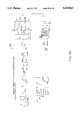
- FIG. 7a diagram of an example coupler which can be used as coupler 68 or coupler 70.
- Couplers 68 and 70actually comprise a pair of couplers in order to provide a full 6 megahertz video signal.
- the "A" and “B” designationscorrespond to the inputs to the coupler from transmitter 66 (see FIG. 6) in the transmit mode and the output from coupler 70 (see FIG. 8) in the receive mode.
- Coils 100 and 102represent the dielectric core (air core) couplers described in Applicant's copending patent application, U.S. application Ser. No. 08/180,421, filed Jan. 11, 1994.
- the couplersare designed for use with grounded (three conductor) electrical outlets and wire, ground connections are shown in FIG. 7.
- Couplers 68 and 70match the characteristic impedance of the AC electrical wiring using a dielectric core coil.
- Receiver mixer 72contains an adder circuit 104 with inputs "A” and “B", corresponding to outputs "A” and “B” of coupler 70 shown in FIG. 7. Inputs "A” and “B” each receive signals with a bandwidth of 3 MHZ, which when added together in adder circuit 104 recreate the 6 MHZ video signal.
- bandpass filter 108(an example schematic diagram of which is shown in FIG. 9).
- Bandpass filter 108 in the exemplary embodiment shown in FIG. 8allows the 18-24 MHZ signal to pass through, filtering out any remaining signal.
- the output signal from bandpass filter 108enters mixer 110 which is Part No. NE612 from Phillips, which mixes in a signal (difference signal) from receiver oscillator 74 to up-convert the 6 MHZ video signal to the channel 3 (60-66 MHZ) or channel 4 (66-72 MHZ) frequency.
- the up-converted signalpasses through an amplifier 112, producing an output signal, which is fed into elliptic bandpass filter 76.
- Example bandpass filter 108is tuned to allow the 18-24 MHZ signal to pass, filtering out other frequencies.
- Example elliptic bandpass filter 76is a Bessel filter, which is a linear filter. It is tuned to pass the 60-66 MHZ signal and filter out other signals. It is comprised of capacitive and inductive components.
- FIG. 11a schematic diagram of an example Automatic Gain Control (AGC) 80.
- AGC 80receives its input from elliptic bandpass filter 76 in receiver section 56.
- AGC 80provides increased gain to television 44 to enhance picture quality.
- AGC 80includes several amplifiers, namely amplifier 114 (part no. CLC522 by Comlinear), amplifier 116 (part no. CLC401 by Comlinear) and amplifier 118 (part no. CLC420 by Comlinear).
- a potentiometer 120is used to set the output level by allowing a DC voltage adjustment of plus or minus one volt.
- a television set such as television 44may be capable of having an input in the 1 volt, peak to peak range.
- AGC 80is tuned to provide an output (input to television 44) of approximately 1 volt, peak to peak.
- Using AGC 80expands the effective distance (for receiving a signal) of system 10 by allowing a remote device to be wired with up to approximately an additional 1000 feet of electrical wiring between the remote device and a distribution device.
- system 10could also be used with twisted pair wiring (telephone wiring) instead of AC electrical wiring.
- twisted pair wiringtelephone wiring
- a system involving twisted pair wiringincreases the distance which a useable signal can travel to approximately 20,000 feet.
- the present systemhas been described as allowing the simultaneous, use of four independent television set because of the four six megahertz bands that can be used between 2 and 30 megahertz. This does not prevent, the use of multiple, dependent viewing/recording devices. For example, if one television set has a PLVC tuned to a particular cable television channel, using one of the four bands which have been allocated between 2 and 30 megahertz, additional PLVC units, tuned to the same band could be used, allowing additional viewing/recording devices to tune to the same channel. Such a set up would be advantageous for applications where multiple viewings of the same program are necessary, such as in schools, businesses and conferences.
- FIG. 13depicts an improved receiver filtering front end which is comprised of a plurality of filter units, 130, 132 and 134, each of which are tuned to provide a flat response across the bandwidth for each video signal which is 6 MHZ.
- lower band coupler 103would be tuned to have a flat band past response on the first two MHZ
- mid-band coupler 132is designed to provide a flat band pass on the next two MHZ of said video signal
- high band coupler 134is designed to provide a flat response over the top two MHZ of a 6 MHZ video signal.
- the AC signal which is carrying the video informationis introduced at input 136 in FIG. 13 and is distributed from AC input 136 in a parallel fashion to the input of each coupler which comprises the filter group 138.
- the output of each coupleris combined at output 140.
- Output 140is introduced into the input of the inverting amplifier 142 for processing the filter output.
- the output of amplifier 142is further introduced through band pass filter 152 before providing a filter output to be introduced to receiver attenuator 146.
- receiver interface 144is introduced into the input of receiver attenuator 146 detailed in FIG. 15.
- the construction and operation of attenuator 146upon review of the schematic diagram disclosed, will be understood by those skilled in the art and is controlled, in part, from an automatic gain control output signal generated receiver AGC 148 shown generally in FIG. 12.
- receiver AGC 148is shown in its detail as provided in the preferred embodiment.
- Receiver AGC 148also acts as a mixer to essentially provide a video signal selected, converted to a broadcast frequency in which a common TV receiver or other monitor can be tuned without modification.
- the input of the receiver AGC 148is a high frequency RF signal containing the video to be decoded, introduced from a attenuator 146.
- the mixer disclosed in the preferred embodimentallows the ability of the user to select an IF frequency by selecting which crystal is used in the mixer to provide for an output in either broadcast TV channel 3 or channel 4, as may be desired by the user.
- Comparator 154provides an improved AGC signal for feeding back to a attenuator 146 depicted generally in FIG. 13. Working off a noise threshold, comparator 154 provides a positive signal to a attenuator 146 when the threshold video signal is adequate to provide good reception of the signal being decoded from the AC line. It can be appreciated that comparator 154 will select zero output such to send a signal to a attenuator 146 through its AGC output to provide for little or no amplification of the signal, unless a signal is actually being received of sufficient strength to be useable.
- An important feature of this new AGC 148is the use of the comparator, where the preferred embodiment is a component type LM 393 shown in the schematic depicted in FIG. 14.
- a comparator for an AGC circuitthere is an enhancement processing of the video.
- AGC circuitsgenerally provide a linear output, increasing with the increase of input signal until a certain threshold is reached.
- thresholdconventionally AGC circuits general begin to hold the output amplitude of the signal it is processing at a given design level regardless of the continuing increase of the input signal.
- Comparator 154provides almost no output, regardless of any input signal being present in the Comparator 154 unless and until a given design threshold level is reached.
- Such threshold levelis normally the minimum useable signal which would provide an acceptable picture in the video system disclosed in the present invention.
- the Comparator circuit switchis on and provides a constant output shown at 158 in FIG. 14.
- FIG. 15shows receive attenuator 146, which receives the output of the AGC circuit described in FIG. 14.
- FIG. 16block diagram of the AC video transmitter 218 is shown.
- the output of an RF video generating devicesis connected to RF input 208.
- An RF generating device or sourcecan be a CATV signal introduced into a home, or a video cassette recorder which has an output which is normally connected to a standard TV receiver as earlier described.
- RF input at 208is introduced into video modulator and AGC 200 which processes the signal so that in its preparation or being mixed to a suitable frequency for AC power line transmission.
- the output of AGC 200is introduced into the mixer amplifier 202, which is described in more detail in FIG. 19.
- Output of mixer 202is introduced in a line driver 204 which provides the coupling circuits and the filter pass band couplers which are similar to those described in the receive circuit.
- Infrared transmitter 220is utilized to provide for remote control access of the RF video generation device, whether it be a cable TV interface, a video cassette recorder or some other device located at a central location in the home. Should one wish to have control of the remote device, such as a VCR, which is not within view of the infrared hand held transmitter, commonly used with such devices, it can be appreciated that remote transmission of the IR signal will be necessary. In a similar fashion to that of a video signal, it is possible to receive the infrared remote control commands locally, using a device with an IR receiver placed next to the TV monitor being used.
- IR signalsare converted and transmitted over the power line using the same technology disclosed for the video signal and detailed herewith.
- the infrared transmission control signalsare thereby transmitted over the power wiring of the house, similar to the video being used, and received at the remote location where the VCR is introducing a video signal to a transmitter such as that depicted generally in 218.
- Infrared command signalsare converted back to infrared through a transmitter, the output infrared device is placed in the proximity of the video device being used, such as a VCR, so that the reproduced infrared signals can be retransmitted to the infrared input within the VCR.
- the infrared signals from the hand held device in the hands of the operatorare relayed through the AC power line and are thereby retransmitted to a location which is an infrared line of sight device being controlled.
- FIG. 17a schematic diagram depicting line driver 204 is shown.
- An improved feature line driver 204is transmitter filter group 203, which is comprised of three separate band pass filters 212, 214 and 216.
- each of the filters in group 203are tuned to prove relatively flat band pass of approximately of 2 MHZ of the 6 MHZ video signal being processed.
- parallel band pass filtersas described in both the receiver and the transmitter, it is possible to get a smoother and flatter band pass over the 6 MHZ spectrum desired.
- there is linear phase shift over the band pass in questionproviding a superior signal response to those coupler devices which utilize other coupling systems, such as ferrite core and other coupling technologies.
- the deviceis referred to as couplers in the diagrams are detailed in appended patent application entitled Improved Transformer Coupler for Communications Over Various Lines appended herewith.
- video AGC 200is described in detail.
- FIG. 19provides a detailed description of transmitter mixer 202, showing particularly the mixing circuit utilized including the ability to select an IF frequency by selection of particular IF crystal selector switch 222.
- the output of transmitter mixer 202 in FIG. 19 coupled to the line driver in 204is described in FIG. 16.
- FIG. 20depicts an infrared receiver system to be used in conjunction with infrared transmitter 220.
- FIG. 21illustrates a preferred embodiment of the IR transmitter 220. It will be appreciated that the IR receiver in FIG. 20 and the IR transmitter in FIG. 21 work in conjunction to provide the remote control of the video device as described above.
Landscapes
- Engineering & Computer Science (AREA)
- Signal Processing (AREA)
- Computer Networks & Wireless Communication (AREA)
- Power Engineering (AREA)
- Multimedia (AREA)
- Cable Transmission Systems, Equalization Of Radio And Reduction Of Echo (AREA)
Abstract
Description
Claims (14)
Priority Applications (1)
| Application Number | Priority Date | Filing Date | Title |
|---|---|---|---|
| US08/526,871US5625863A (en) | 1989-04-28 | 1995-09-12 | Video distribution system using in-wall wiring |
Applications Claiming Priority (7)
| Application Number | Priority Date | Filing Date | Title |
|---|---|---|---|
| US34490789A | 1989-04-28 | 1989-04-28 | |
| US42920889A | 1989-10-30 | 1989-10-30 | |
| US51557890A | 1990-04-26 | 1990-04-26 | |
| US82232992A | 1992-01-17 | 1992-01-17 | |
| US18042194A | 1994-01-11 | 1994-01-11 | |
| US08/304,495US5592482A (en) | 1989-04-28 | 1994-09-12 | Video distribution system using in-wall wiring |
| US08/526,871US5625863A (en) | 1989-04-28 | 1995-09-12 | Video distribution system using in-wall wiring |
Related Parent Applications (1)
| Application Number | Title | Priority Date | Filing Date |
|---|---|---|---|
| US08/304,495Continuation-In-PartUS5592482A (en) | 1989-04-28 | 1994-09-12 | Video distribution system using in-wall wiring |
Publications (1)
| Publication Number | Publication Date |
|---|---|
| US5625863Atrue US5625863A (en) | 1997-04-29 |
Family
ID=27558707
Family Applications (1)
| Application Number | Title | Priority Date | Filing Date |
|---|---|---|---|
| US08/526,871Expired - LifetimeUS5625863A (en) | 1989-04-28 | 1995-09-12 | Video distribution system using in-wall wiring |
Country Status (1)
| Country | Link |
|---|---|
| US (1) | US5625863A (en) |
Cited By (112)
| Publication number | Priority date | Publication date | Assignee | Title |
|---|---|---|---|---|
| NL1007849C2 (en)* | 1997-12-19 | 1999-06-24 | Tratec Telecom B V | Communication system for CATV with integrated data channel. |
| US6014386A (en)* | 1989-10-30 | 2000-01-11 | Videocom, Inc. | System and method for high speed communication of video, voice and error-free data over in-wall wiring |
| US6040759A (en)* | 1998-02-17 | 2000-03-21 | Sanderson; Lelon Wayne | Communication system for providing broadband data services using a high-voltage cable of a power system |
| US6137865A (en)* | 1998-09-28 | 2000-10-24 | Broadmedia, Inc. | Transmission and reception of data over a home network implemented upon a phone line system |
| US20010054953A1 (en)* | 2000-04-14 | 2001-12-27 | Kline Paul A. | Digital communications utilizing medium voltage power distribution lines |
| US20020002040A1 (en)* | 2000-04-19 | 2002-01-03 | Kline Paul A. | Method and apparatus for interfacing RF signals to medium voltage power lines |
| EP0992118A4 (en)* | 1997-06-27 | 2002-01-09 | Videocom Inc | Transmission of fm video signals over various lines |
| US20020039388A1 (en)* | 2000-02-29 | 2002-04-04 | Smart Kevin J. | High data-rate powerline network system and method |
| US20020097953A1 (en)* | 2000-12-15 | 2002-07-25 | Kline Paul A. | Interfacing fiber optic data with electrical power systems |
| US20020118101A1 (en)* | 2001-02-14 | 2002-08-29 | Kline Paul A. | Data communication over a power line |
| US6456192B1 (en) | 2000-04-19 | 2002-09-24 | Phonex Broadband Corporation | Method and system for power line null detection and automatic frequency and gain control |
| FR2823406A1 (en)* | 2001-04-05 | 2002-10-11 | France Telecom | SYSTEM FOR TRANSMITTING HIGH-SPEED INFORMATION TO A DIGITAL TERMINAL |
| FR2823407A1 (en)* | 2001-04-05 | 2002-10-11 | France Telecom | High speed data supply system uses modulation on low voltage power line to provide digital services to remote subscriber station |
| US6496104B2 (en) | 2000-03-15 | 2002-12-17 | Current Technologies, L.L.C. | System and method for communication via power lines using ultra-short pulses |
| US20030007503A1 (en)* | 2000-12-26 | 2003-01-09 | Wolfgang Daum | Method and apparatus for interfacing a power line carrier and an appliance |
| US20030046377A1 (en)* | 2000-12-27 | 2003-03-06 | Wolfgang Daum | Method and apparatus for appliance service diagnostics |
| US6571393B1 (en) | 1998-05-27 | 2003-05-27 | The Hong Kong University Of Science And Technology | Data transmission system |
| US20030099078A1 (en)* | 2001-11-27 | 2003-05-29 | Parlee Brad E. | Phase coupler |
| US20030169155A1 (en)* | 2000-04-14 | 2003-09-11 | Mollenkopf James Douglas | Power line communication system and method of using the same |
| US20030179080A1 (en)* | 2001-12-21 | 2003-09-25 | Mollenkopf James Douglas | Facilitating communication of data signals on electric power systems |
| US20030190110A1 (en)* | 2001-02-14 | 2003-10-09 | Kline Paul A. | Method and apparatus for providing inductive coupling and decoupling of high-frequency, high-bandwidth data signals directly on and off of a high voltage power line |
| US6637030B1 (en)* | 1997-04-09 | 2003-10-21 | Micron Technology, Inc. | Broadband cable television and computer network |
| US20030234713A1 (en)* | 2002-06-21 | 2003-12-25 | Pridmore Charles Franklin | Power line coupling device and method of using the same |
| US20040032958A1 (en)* | 2002-08-19 | 2004-02-19 | Samsung Electronics Co., Ltd. | Wiring system for audiovisual devices and audiovisual system using the same |
| US6711385B1 (en) | 2000-07-06 | 2004-03-23 | Satius, Inc. | Coupler for wireless communications |
| US20040056734A1 (en)* | 2001-05-18 | 2004-03-25 | Davidow Clifford A. | Medium voltage signal coupling structure for last leg power grid high-speed data network |
| US20040067745A1 (en)* | 2002-10-02 | 2004-04-08 | Amperion, Inc. | Method and system for signal repeating in powerline communications |
| US20040073086A1 (en)* | 2002-07-16 | 2004-04-15 | Fuji Photo Optical Co., Ltd. | Electronic endoscope apparatus which superimposes signals on power supply |
| US20040110483A1 (en)* | 2002-12-10 | 2004-06-10 | Mollenkopf James Douglas | Power line communication sytem and method |
| US20040113756A1 (en)* | 2002-12-10 | 2004-06-17 | Mollenkopf James Douglas | Device and method for coupling with electrical distribution network infrastructure to provide communications |
| US20040113757A1 (en)* | 2002-12-10 | 2004-06-17 | White Melvin Joseph | Power line communication system and method of operating the same |
| US20040125819A1 (en)* | 2001-07-05 | 2004-07-01 | Yehuda Binder | Telephone outlet with packet telephony adapter, and a network using same |
| US20040135676A1 (en)* | 2002-12-10 | 2004-07-15 | Berkman William H. | Power line communication system and method of operating the same |
| US20040142599A1 (en)* | 2003-01-21 | 2004-07-22 | Cope Leonard D. | Power line coupling device and method of using the same |
| US6778646B1 (en)* | 1999-11-04 | 2004-08-17 | 2Wire, Inc. | System and method for coupling multiple home networks |
| US20040170189A1 (en)* | 1998-07-28 | 2004-09-02 | Israeli Company Of Serconet Ltd. | Local area network of serial intellegent cells |
| US6812970B1 (en)* | 2000-05-15 | 2004-11-02 | Mcbride Richard L. | Video camera utilizing power line modulation |
| US20040227622A1 (en)* | 2003-05-13 | 2004-11-18 | Giannini Paul M. | Device and method for communicating data signals through multiple power line conductors |
| US20040227621A1 (en)* | 2000-04-14 | 2004-11-18 | Cope Leonard D. | Power line communication apparatus and method of using the same |
| US20040246107A1 (en)* | 2001-02-14 | 2004-12-09 | Current Technologies, L.L.C. | Power line communication system and method of using the same |
| US20050018766A1 (en)* | 2003-07-21 | 2005-01-27 | Sony Corporation And Sony Electronics, Inc. | Power-line communication based surveillance system |
| US20050151848A1 (en)* | 2004-01-09 | 2005-07-14 | Jean Wang | Image transmitter |
| US20050168326A1 (en)* | 2002-12-10 | 2005-08-04 | Current Technologies, Llc | Power line repeater system and method |
| US20050169401A1 (en)* | 2004-02-02 | 2005-08-04 | Satius, Inc. | Frequency modulated OFDM over various communication media |
| US20050249245A1 (en)* | 2004-05-06 | 2005-11-10 | Serconet Ltd. | System and method for carrying a wireless based signal over wiring |
| FR2871327A1 (en)* | 2004-06-08 | 2005-12-09 | Defidev | LOCAL AUDIOVISUAL DISTRIBUTION |
| US20050277328A1 (en)* | 2000-04-19 | 2005-12-15 | Serconet Ltd | Network combining wired and non-wired segments |
| US6977578B2 (en) | 2000-01-20 | 2005-12-20 | Current Technologies, Llc | Method of isolating data in a power line communications network |
| US6980089B1 (en) | 2000-08-09 | 2005-12-27 | Current Technologies, Llc | Non-intrusive coupling to shielded power cable |
| US6982611B2 (en) | 2002-06-24 | 2006-01-03 | Current Technologies, Llc | Power line coupling device and method of using the same |
| US20060049693A1 (en)* | 2004-09-08 | 2006-03-09 | Satius, Inc. | Apparatus and method for transmitting digital data over various communication media |
| US7027431B1 (en)* | 1998-07-10 | 2006-04-11 | Upstate Systems Tec, Inc. | Wireless device connection in single medium wiring scheme for multiple signal distribution in building and access port therefor |
| US20060097573A1 (en)* | 2004-10-26 | 2006-05-11 | Gidge Brett D | Power line communications system and method of operating the same |
| US20060125609A1 (en)* | 2000-08-09 | 2006-06-15 | Kline Paul A | Power line coupling device and method of using the same |
| US20060149829A1 (en)* | 2004-12-31 | 2006-07-06 | Ta-Chiun Kuan | Monitor system |
| US7076378B1 (en) | 2002-11-13 | 2006-07-11 | Current Technologies, Llc | Device and method for providing power line characteristics and diagnostics |
| US20060182094A1 (en)* | 2000-04-18 | 2006-08-17 | Serconet Ltd. | Telephone communication system over a single telephone line |
| US7113134B1 (en) | 2004-03-12 | 2006-09-26 | Current Technologies, Llc | Transformer antenna device and method of using the same |
| US20060245355A1 (en)* | 2005-04-28 | 2006-11-02 | Sony Corporation | Bandwith management in a network |
| US20060244571A1 (en)* | 2005-04-29 | 2006-11-02 | Yaney David S | Power line coupling device and method of use |
| US7132819B1 (en) | 2002-11-12 | 2006-11-07 | Current Technologies, Llc | Floating power supply and method of using the same |
| US20060255930A1 (en)* | 2005-05-12 | 2006-11-16 | Berkman William H | Power line communications system and method |
| US20060291575A1 (en)* | 2003-07-03 | 2006-12-28 | Berkman William H | Power Line Communication System and Method |
| US20070017974A1 (en)* | 2005-07-22 | 2007-01-25 | Joao Raymond A | Transaction security apparatus and method |
| US7173938B1 (en) | 2001-05-18 | 2007-02-06 | Current Grid, Llc | Method and apparatus for processing outbound data within a powerline based communication system |
| US7194528B1 (en) | 2001-05-18 | 2007-03-20 | Current Grid, Llc | Method and apparatus for processing inbound data within a powerline based communication system |
| US20070070911A1 (en)* | 2005-09-29 | 2007-03-29 | Goldberg Keith J | Method for testing links in a wireless network |
| US7199699B1 (en) | 2002-02-19 | 2007-04-03 | Current Technologies, Llc | Facilitating communication with power line communication devices |
| US20070075800A1 (en)* | 2003-11-18 | 2007-04-05 | Lee Sam H | Device for indivisual control of multiple circuit-unit using single cable and method thereof |
| US20070136766A1 (en)* | 2005-12-09 | 2007-06-14 | Ryuichi Iwamura | Cross-phase adapter for powerline communications (PLC) network |
| US7245201B1 (en) | 2000-08-09 | 2007-07-17 | Current Technologies, Llc | Power line coupling device and method of using the same |
| US20070173202A1 (en)* | 2006-01-11 | 2007-07-26 | Serconet Ltd. | Apparatus and method for frequency shifting of a wireless signal and systems using frequency shifting |
| US20070201494A1 (en)* | 2002-06-07 | 2007-08-30 | Heng Lou | Last Leg Utility Grid High-Speed Data Communication Network Having Virtual Local Area Network Functionality |
| US7265664B2 (en) | 2005-04-04 | 2007-09-04 | Current Technologies, Llc | Power line communications system and method |
| US20070273205A1 (en)* | 2006-05-22 | 2007-11-29 | Denso Corporation | Communication system for use in data communications between power generator and external unit |
| US7308103B2 (en) | 2003-05-08 | 2007-12-11 | Current Technologies, Llc | Power line communication device and method of using the same |
| US7317793B2 (en) | 2003-01-30 | 2008-01-08 | Serconet Ltd | Method and system for providing DC power on local telephone lines |
| US7340509B2 (en) | 2002-07-18 | 2008-03-04 | General Electric Company | Reconfigurable appliance control system |
| CN100397900C (en)* | 2006-03-02 | 2008-06-25 | 苏州有线电视网络股份有限公司 | Multi-route radio frequency remote back transmission signal monitoring system for cable TV two-way network |
| US7436842B2 (en) | 2001-10-11 | 2008-10-14 | Serconet Ltd. | Outlet with analog signal adapter, a method for use thereof and a network using said outlet |
| FR2915042A1 (en)* | 2007-04-10 | 2008-10-17 | Patrick Gilles Maillot | Digital media e.g. audio content, distributing system for e.g. TV set, has case containing different digital data receiving systems for transporting digital data between master unit and mobile unit through powerline communication |
| US7460467B1 (en) | 2003-07-23 | 2008-12-02 | Current Technologies, Llc | Voice-over-IP network test device and method |
| US20090002094A1 (en)* | 2007-06-26 | 2009-01-01 | Radtke William O | Power Line Coupling Device and Method |
| US20090002137A1 (en)* | 2007-06-26 | 2009-01-01 | Radtke William O | Power Line Coupling Device and Method |
| US7483524B2 (en) | 1999-07-20 | 2009-01-27 | Serconet, Ltd | Network for telephony and data communication |
| US20090085726A1 (en)* | 2007-09-27 | 2009-04-02 | Radtke William O | Power Line Communications Coupling Device and Method |
| US7522714B2 (en) | 2000-03-20 | 2009-04-21 | Serconet Ltd. | Telephone outlet for implementing a local area network over telephone lines and a local area network using such outlets |
| US20090102680A1 (en)* | 1997-09-17 | 2009-04-23 | Roos Charles E | Multifunction data port providing an interface between a digital network and electronics in residential or commercial structures |
| US20090172749A1 (en)* | 2007-12-28 | 2009-07-02 | Echostar Technologies Corporation | Remodulating satellite tv channels for home distribution |
| US20090237506A1 (en)* | 2005-10-12 | 2009-09-24 | Valeo Etudes Electroniques | System for Communication Between a Video Image Acquisition Unit and an on-Board Computer for a Motor Vehicle |
| US20090247006A1 (en)* | 2008-01-22 | 2009-10-01 | Wi3, Inc., New York | Network access point having interchangeable cartridges |
| US20090316052A1 (en)* | 2006-03-24 | 2009-12-24 | Remo Tek. Co., Ltd. | Circuit for transmitting/receiving video signal using power line |
| US7656904B2 (en) | 2003-03-13 | 2010-02-02 | Mosaid Technologies Incorporated | Telephone system having multiple distinct sources and accessories therefor |
| US20100045863A1 (en)* | 2007-05-15 | 2010-02-25 | Lg Electronics Inc. | System for displaying image and method for controlling the same |
| US7675897B2 (en) | 2005-09-06 | 2010-03-09 | Current Technologies, Llc | Power line communications system with differentiated data services |
| US7686653B2 (en) | 2003-09-07 | 2010-03-30 | Mosaid Technologies Incorporated | Modular outlet |
| US7764943B2 (en) | 2006-03-27 | 2010-07-27 | Current Technologies, Llc | Overhead and underground power line communication system and method using a bypass |
| US20100226380A1 (en)* | 2009-03-03 | 2010-09-09 | Aboundi, Inc. | Transmission line adapter and system |
| US7873058B2 (en) | 2004-11-08 | 2011-01-18 | Mosaid Technologies Incorporated | Outlet with analog signal adapter, a method for use thereof and a network using said outlet |
| US20110018704A1 (en)* | 2009-07-24 | 2011-01-27 | Burrows Zachary M | System, Device and Method for Providing Power Line Communications |
| WO2011021927A1 (en)* | 2009-08-21 | 2011-02-24 | Alltrifix B.V. | System and method for communication between an electronic device and a computer |
| US8175649B2 (en) | 2008-06-20 | 2012-05-08 | Corning Mobileaccess Ltd | Method and system for real time control of an active antenna over a distributed antenna system |
| US8279058B2 (en) | 2008-11-06 | 2012-10-02 | Current Technologies International Gmbh | System, device and method for communicating over power lines |
| US8582598B2 (en) | 1999-07-07 | 2013-11-12 | Mosaid Technologies Incorporated | Local area network for distributing data communication, sensing and control signals |
| US8594133B2 (en) | 2007-10-22 | 2013-11-26 | Corning Mobileaccess Ltd. | Communication system using low bandwidth wires |
| US8897215B2 (en) | 2009-02-08 | 2014-11-25 | Corning Optical Communications Wireless Ltd | Communication system using cables carrying ethernet signals |
| US9184960B1 (en) | 2014-09-25 | 2015-11-10 | Corning Optical Communications Wireless Ltd | Frequency shifting a communications signal(s) in a multi-frequency distributed antenna system (DAS) to avoid or reduce frequency interference |
| US20150365732A1 (en)* | 2014-06-12 | 2015-12-17 | Eagle Comtronics, Inc. | Legacy converter filter with extended frequency range |
| US9338823B2 (en) | 2012-03-23 | 2016-05-10 | Corning Optical Communications Wireless Ltd | Radio-frequency integrated circuit (RFIC) chip(s) for providing distributed antenna system functionalities, and related components, systems, and methods |
| US20160175971A1 (en)* | 2014-12-18 | 2016-06-23 | Illinois Tool Works Inc. | Systems and methods for measuring characteristics of a welding cable with a low power transceiver |
| US10449614B2 (en) | 2014-12-18 | 2019-10-22 | Illinois Tool Works Inc. | Systems and methods for solid state sensor measurements of welding cables |
| US10986165B2 (en) | 2004-01-13 | 2021-04-20 | May Patents Ltd. | Information device |
Citations (7)
| Publication number | Priority date | Publication date | Assignee | Title |
|---|---|---|---|---|
| US4412553A (en)* | 1981-06-25 | 1983-11-01 | Baxter Travenol Laboratories, Inc. | Device to control the transmembrane pressure in a plasmapheresis system |
| US4994909A (en)* | 1989-05-04 | 1991-02-19 | Northern Telecom Limited | Video signal distribution system |
| US5010399A (en)* | 1989-07-14 | 1991-04-23 | Inline Connection Corporation | Video transmission and control system utilizing internal telephone lines |
| US5247347A (en)* | 1991-09-27 | 1993-09-21 | Bell Atlantic Network Services, Inc. | Pstn architecture for video-on-demand services |
| US5327230A (en)* | 1989-09-20 | 1994-07-05 | Dockery Gregory A | Video multiplying system |
| US5334975A (en)* | 1991-07-16 | 1994-08-02 | Wachob David E | Residential time reference system |
| US5351272A (en)* | 1992-05-18 | 1994-09-27 | Abraham Karoly C | Communications apparatus and method for transmitting and receiving multiple modulated signals over electrical lines |
- 1995
- 1995-09-12USUS08/526,871patent/US5625863A/ennot_activeExpired - Lifetime
Patent Citations (7)
| Publication number | Priority date | Publication date | Assignee | Title |
|---|---|---|---|---|
| US4412553A (en)* | 1981-06-25 | 1983-11-01 | Baxter Travenol Laboratories, Inc. | Device to control the transmembrane pressure in a plasmapheresis system |
| US4994909A (en)* | 1989-05-04 | 1991-02-19 | Northern Telecom Limited | Video signal distribution system |
| US5010399A (en)* | 1989-07-14 | 1991-04-23 | Inline Connection Corporation | Video transmission and control system utilizing internal telephone lines |
| US5327230A (en)* | 1989-09-20 | 1994-07-05 | Dockery Gregory A | Video multiplying system |
| US5334975A (en)* | 1991-07-16 | 1994-08-02 | Wachob David E | Residential time reference system |
| US5247347A (en)* | 1991-09-27 | 1993-09-21 | Bell Atlantic Network Services, Inc. | Pstn architecture for video-on-demand services |
| US5351272A (en)* | 1992-05-18 | 1994-09-27 | Abraham Karoly C | Communications apparatus and method for transmitting and receiving multiple modulated signals over electrical lines |
Non-Patent Citations (14)
| Title |
|---|
| "Color Bursts", Communications Engineering and Design, p. 10, (Nov. 1992). |
| "Transmission of Full-Motion Analog and Digital Video and other Wideband Signals over the Twisted Pair Wiring Internal and Apartment and Office Buildings", Inline Connection Corporation, pp. 1-19, (Jul. 1993). |
| Color Bursts , Communications Engineering and Design, p. 10, (Nov. 1992).* |
| David D. Goodman, "Distribution of Broadband Signals to the Individual Units of an Apartment Building using Internal Telephone Wires", Inline Connection Corporation Standards Project, pp. 1-6, (Aug. 1993). |
| David D. Goodman, "On 2-Way Broadband Communication over POTS Internal to the Residence", Inline Connection Corporation Standards Project, pp. 1-19, (Oct. 1993). |
| David D. Goodman, "Using the IEEE LAN Coding System to Communicate Bitstreams across Internal Telephone Wiring (in Coordination with Transmission of Analog Video)", Inline Connection Corporation Standards Project, pp. 1-9, (Nov. 1993). |
| David D. Goodman, "Using the Telephone Wires Internal to a Residence for the Distribution of Broadband Signals to Settops and Computers", Inline Connection Corporation Standards Project, pp. 1-14, (Aug. 1993). |
| David D. Goodman, Distribution of Broadband Signals to the Individual Units of an Apartment Building using Internal Telephone Wires , Inline Connection Corporation Standards Project, pp. 1 6, (Aug. 1993).* |
| David D. Goodman, On 2 Way Broadband Communication over POTS Internal to the Residence , Inline Connection Corporation Standards Project, pp. 1 19, (Oct. 1993).* |
| David D. Goodman, Using the IEEE LAN Coding System to Communicate Bitstreams across Internal Telephone Wiring (in Coordination with Transmission of Analog Video) , Inline Connection Corporation Standards Project, pp. 1 9, (Nov. 1993).* |
| David D. Goodman, Using the Telephone Wires Internal to a Residence for the Distribution of Broadband Signals to Settops and Computers , Inline Connection Corporation Standards Project, pp. 1 14, (Aug. 1993).* |
| Eric Miller, "Creating a critical vehicle for the new `information superhighways`", Microware Interactive Digital Television Networks, pp. 1-6. |
| Eric Miller, Creating a critical vehicle for the new information superhighways , Microware Interactive Digital Television Networks, pp. 1 6.* |
| Transmission of Full Motion Analog and Digital Video and other Wideband Signals over the Twisted Pair Wiring Internal and Apartment and Office Buildings , Inline Connection Corporation, pp. 1 19, (Jul. 1993).* |
Cited By (270)
| Publication number | Priority date | Publication date | Assignee | Title |
|---|---|---|---|---|
| US6014386A (en)* | 1989-10-30 | 2000-01-11 | Videocom, Inc. | System and method for high speed communication of video, voice and error-free data over in-wall wiring |
| US20040060072A1 (en)* | 1997-04-09 | 2004-03-25 | Klein Dean A. | Broadband cable television and computer network |
| US6637030B1 (en)* | 1997-04-09 | 2003-10-21 | Micron Technology, Inc. | Broadband cable television and computer network |
| EP0992118A4 (en)* | 1997-06-27 | 2002-01-09 | Videocom Inc | Transmission of fm video signals over various lines |
| US20090102680A1 (en)* | 1997-09-17 | 2009-04-23 | Roos Charles E | Multifunction data port providing an interface between a digital network and electronics in residential or commercial structures |
| FR2773037A1 (en)* | 1997-12-19 | 1999-06-25 | Tratec Telecom Bv | CATV communication system |
| NL1007849C2 (en)* | 1997-12-19 | 1999-06-24 | Tratec Telecom B V | Communication system for CATV with integrated data channel. |
| US6040759A (en)* | 1998-02-17 | 2000-03-21 | Sanderson; Lelon Wayne | Communication system for providing broadband data services using a high-voltage cable of a power system |
| US6571393B1 (en) | 1998-05-27 | 2003-05-27 | The Hong Kong University Of Science And Technology | Data transmission system |
| US7027431B1 (en)* | 1998-07-10 | 2006-04-11 | Upstate Systems Tec, Inc. | Wireless device connection in single medium wiring scheme for multiple signal distribution in building and access port therefor |
| US8885660B2 (en) | 1998-07-28 | 2014-11-11 | Conversant Intellectual Property Management Incorporated | Local area network of serial intelligent cells |
| US20040174897A1 (en)* | 1998-07-28 | 2004-09-09 | Israeli Company Of Serconet Ltd. | Local area network of serial intellegent cells |
| US20060018339A1 (en)* | 1998-07-28 | 2006-01-26 | Serconet, Ltd | Local area network of serial intelligent cells |
| US7006523B2 (en) | 1998-07-28 | 2006-02-28 | Serconet Ltd. | Local area network of serial intelligent cells |
| US8867523B2 (en) | 1998-07-28 | 2014-10-21 | Conversant Intellectual Property Management Incorporated | Local area network of serial intelligent cells |
| US20060056444A1 (en)* | 1998-07-28 | 2006-03-16 | Serconet, Ltd | Local area network of serial intelligent cells |
| US7016368B2 (en) | 1998-07-28 | 2006-03-21 | Serconet, Ltd. | Local area network of serial intelligent cells |
| US7830858B2 (en) | 1998-07-28 | 2010-11-09 | Mosaid Technologies Incorporated | Local area network of serial intelligent cells |
| US7852874B2 (en) | 1998-07-28 | 2010-12-14 | Mosaid Technologies Incorporated | Local area network of serial intelligent cells |
| US7035280B2 (en) | 1998-07-28 | 2006-04-25 | Serconet Ltd. | Local area network of serial intelligent cells |
| US7424031B2 (en) | 1998-07-28 | 2008-09-09 | Serconet, Ltd. | Local area network of serial intelligent cells |
| US7653015B2 (en) | 1998-07-28 | 2010-01-26 | Mosaid Technologies Incorporated | Local area network of serial intelligent cells |
| US8885659B2 (en) | 1998-07-28 | 2014-11-11 | Conversant Intellectual Property Management Incorporated | Local area network of serial intelligent cells |
| US7965735B2 (en) | 1998-07-28 | 2011-06-21 | Mosaid Technologies Incorporated | Local area network of serial intelligent cells |
| US7095756B2 (en) | 1998-07-28 | 2006-08-22 | Serconet, Ltd. | Local area network of serial intelligent cells |
| US20060251110A1 (en)* | 1998-07-28 | 2006-11-09 | Isreali Company Of Serconet Ltd. | Local area network of serial intelligent cells |
| US7978726B2 (en) | 1998-07-28 | 2011-07-12 | Mosaid Technologies Incorporated | Local area network of serial intelligent cells |
| US7986708B2 (en) | 1998-07-28 | 2011-07-26 | Mosaid Technologies Incorporated | Local area network of serial intelligent cells |
| US20050163152A1 (en)* | 1998-07-28 | 2005-07-28 | Serconet Ltd. | Local area network of serial intelligent cells |
| US8908673B2 (en) | 1998-07-28 | 2014-12-09 | Conversant Intellectual Property Management Incorporated | Local area network of serial intelligent cells |
| US20050013320A1 (en)* | 1998-07-28 | 2005-01-20 | Serconet Ltd. | Local area network of serial intelligent cells |
| US20060291497A1 (en)* | 1998-07-28 | 2006-12-28 | Israeli Company Of Serconet Ltd. | Local area network of serial intelligent cells |
| US7292600B2 (en) | 1998-07-28 | 2007-11-06 | Serconet Ltd. | Local area network of serial intellegent cells |
| US7187695B2 (en) | 1998-07-28 | 2007-03-06 | Serconet Ltd. | Local area network of serial intelligent cells |
| US20040170189A1 (en)* | 1998-07-28 | 2004-09-02 | Israeli Company Of Serconet Ltd. | Local area network of serial intellegent cells |
| US8270430B2 (en) | 1998-07-28 | 2012-09-18 | Mosaid Technologies Incorporated | Local area network of serial intelligent cells |
| US7221679B2 (en) | 1998-07-28 | 2007-05-22 | Serconet Ltd. | Local area network of serial intelligent cells |
| US8325636B2 (en) | 1998-07-28 | 2012-12-04 | Mosaid Technologies Incorporated | Local area network of serial intelligent cells |
| US6137865A (en)* | 1998-09-28 | 2000-10-24 | Broadmedia, Inc. | Transmission and reception of data over a home network implemented upon a phone line system |
| US8582598B2 (en) | 1999-07-07 | 2013-11-12 | Mosaid Technologies Incorporated | Local area network for distributing data communication, sensing and control signals |
| US7492875B2 (en) | 1999-07-20 | 2009-02-17 | Serconet, Ltd. | Network for telephony and data communication |
| US7522713B2 (en) | 1999-07-20 | 2009-04-21 | Serconet, Ltd. | Network for telephony and data communication |
| US7483524B2 (en) | 1999-07-20 | 2009-01-27 | Serconet, Ltd | Network for telephony and data communication |
| US8351582B2 (en) | 1999-07-20 | 2013-01-08 | Mosaid Technologies Incorporated | Network for telephony and data communication |
| US8929523B2 (en) | 1999-07-20 | 2015-01-06 | Conversant Intellectual Property Management Inc. | Network for telephony and data communication |
| US6778646B1 (en)* | 1999-11-04 | 2004-08-17 | 2Wire, Inc. | System and method for coupling multiple home networks |
| US6977578B2 (en) | 2000-01-20 | 2005-12-20 | Current Technologies, Llc | Method of isolating data in a power line communications network |
| US20020039388A1 (en)* | 2000-02-29 | 2002-04-04 | Smart Kevin J. | High data-rate powerline network system and method |
| US6496104B2 (en) | 2000-03-15 | 2002-12-17 | Current Technologies, L.L.C. | System and method for communication via power lines using ultra-short pulses |
| US8363797B2 (en) | 2000-03-20 | 2013-01-29 | Mosaid Technologies Incorporated | Telephone outlet for implementing a local area network over telephone lines and a local area network using such outlets |
| US7715534B2 (en) | 2000-03-20 | 2010-05-11 | Mosaid Technologies Incorporated | Telephone outlet for implementing a local area network over telephone lines and a local area network using such outlets |
| US7522714B2 (en) | 2000-03-20 | 2009-04-21 | Serconet Ltd. | Telephone outlet for implementing a local area network over telephone lines and a local area network using such outlets |
| US8855277B2 (en) | 2000-03-20 | 2014-10-07 | Conversant Intellectual Property Managment Incorporated | Telephone outlet for implementing a local area network over telephone lines and a local area network using such outlets |
| US20010054953A1 (en)* | 2000-04-14 | 2001-12-27 | Kline Paul A. | Digital communications utilizing medium voltage power distribution lines |
| US7307511B2 (en) | 2000-04-14 | 2007-12-11 | Current Technologies, Llc | Power line communication system and method |
| US7245212B2 (en) | 2000-04-14 | 2007-07-17 | Current Technologies, Llc | Power line communication apparatus and method of using the same |
| US6998962B2 (en) | 2000-04-14 | 2006-02-14 | Current Technologies, Llc | Power line communication apparatus and method of using the same |
| US6958680B2 (en) | 2000-04-14 | 2005-10-25 | Current Technologies, Llc | Power line communication system and method of using the same |
| US20050206507A1 (en)* | 2000-04-14 | 2005-09-22 | Kline Paul A | Power line communication system and method |
| US20040227621A1 (en)* | 2000-04-14 | 2004-11-18 | Cope Leonard D. | Power line communication apparatus and method of using the same |
| US6965302B2 (en) | 2000-04-14 | 2005-11-15 | Current Technologies, Llc | Power line communication system and method of using the same |
| US20030169155A1 (en)* | 2000-04-14 | 2003-09-11 | Mollenkopf James Douglas | Power line communication system and method of using the same |
| US7397791B2 (en) | 2000-04-18 | 2008-07-08 | Serconet, Ltd. | Telephone communication system over a single telephone line |
| US8559422B2 (en) | 2000-04-18 | 2013-10-15 | Mosaid Technologies Incorporated | Telephone communication system over a single telephone line |
| US7593394B2 (en) | 2000-04-18 | 2009-09-22 | Mosaid Technologies Incorporated | Telephone communication system over a single telephone line |
| US8000349B2 (en) | 2000-04-18 | 2011-08-16 | Mosaid Technologies Incorporated | Telephone communication system over a single telephone line |
| US20060182094A1 (en)* | 2000-04-18 | 2006-08-17 | Serconet Ltd. | Telephone communication system over a single telephone line |
| US7466722B2 (en) | 2000-04-18 | 2008-12-16 | Serconet Ltd | Telephone communication system over a single telephone line |
| US8223800B2 (en) | 2000-04-18 | 2012-07-17 | Mosaid Technologies Incorporated | Telephone communication system over a single telephone line |
| US20080043646A1 (en)* | 2000-04-18 | 2008-02-21 | Serconet Ltd. | Telephone communication system over a single telephone line |
| US7197028B2 (en) | 2000-04-18 | 2007-03-27 | Serconet Ltd. | Telephone communication system over a single telephone line |
| US8848725B2 (en) | 2000-04-19 | 2014-09-30 | Conversant Intellectual Property Management Incorporated | Network combining wired and non-wired segments |
| US7633966B2 (en) | 2000-04-19 | 2009-12-15 | Mosaid Technologies Incorporated | Network combining wired and non-wired segments |
| US6456192B1 (en) | 2000-04-19 | 2002-09-24 | Phonex Broadband Corporation | Method and system for power line null detection and automatic frequency and gain control |
| US20020002040A1 (en)* | 2000-04-19 | 2002-01-03 | Kline Paul A. | Method and apparatus for interfacing RF signals to medium voltage power lines |
| US8982904B2 (en) | 2000-04-19 | 2015-03-17 | Conversant Intellectual Property Management Inc. | Network combining wired and non-wired segments |
| US8873575B2 (en) | 2000-04-19 | 2014-10-28 | Conversant Intellectual Property Management Incorporated | Network combining wired and non-wired segments |
| US20050277328A1 (en)* | 2000-04-19 | 2005-12-15 | Serconet Ltd | Network combining wired and non-wired segments |
| US8873586B2 (en) | 2000-04-19 | 2014-10-28 | Conversant Intellectual Property Management Incorporated | Network combining wired and non-wired segments |
| US8867506B2 (en) | 2000-04-19 | 2014-10-21 | Conversant Intellectual Property Management Incorporated | Network combining wired and non-wired segments |
| US6812970B1 (en)* | 2000-05-15 | 2004-11-02 | Mcbride Richard L. | Video camera utilizing power line modulation |
| US6711385B1 (en) | 2000-07-06 | 2004-03-23 | Satius, Inc. | Coupler for wireless communications |
| US6980089B1 (en) | 2000-08-09 | 2005-12-27 | Current Technologies, Llc | Non-intrusive coupling to shielded power cable |
| US7248148B2 (en) | 2000-08-09 | 2007-07-24 | Current Technologies, Llc | Power line coupling device and method of using the same |
| US20060125609A1 (en)* | 2000-08-09 | 2006-06-15 | Kline Paul A | Power line coupling device and method of using the same |
| US7245201B1 (en) | 2000-08-09 | 2007-07-17 | Current Technologies, Llc | Power line coupling device and method of using the same |
| US20020097953A1 (en)* | 2000-12-15 | 2002-07-25 | Kline Paul A. | Interfacing fiber optic data with electrical power systems |
| US20030007503A1 (en)* | 2000-12-26 | 2003-01-09 | Wolfgang Daum | Method and apparatus for interfacing a power line carrier and an appliance |
| US7170405B2 (en) | 2000-12-26 | 2007-01-30 | General Electric Company | Method and apparatus for interfacing a power line carrier and an appliance |
| US20030046377A1 (en)* | 2000-12-27 | 2003-03-06 | Wolfgang Daum | Method and apparatus for appliance service diagnostics |
| US7453352B2 (en) | 2001-02-14 | 2008-11-18 | Current Technologies, Llc | Data communication over a power line |
| US20020121963A1 (en)* | 2001-02-14 | 2002-09-05 | Kline Paul A. | Data communication over a power line |
| US20050213874A1 (en)* | 2001-02-14 | 2005-09-29 | Kline Paul A | Power line communication system and method |
| US7103240B2 (en) | 2001-02-14 | 2006-09-05 | Current Technologies, Llc | Method and apparatus for providing inductive coupling and decoupling of high-frequency, high-bandwidth data signals directly on and off of a high voltage power line |
| US20070287406A1 (en)* | 2001-02-14 | 2007-12-13 | Kline Paul A | Data Communication over a Power Line |
| US20030190110A1 (en)* | 2001-02-14 | 2003-10-09 | Kline Paul A. | Method and apparatus for providing inductive coupling and decoupling of high-frequency, high-bandwidth data signals directly on and off of a high voltage power line |
| US7414518B2 (en) | 2001-02-14 | 2008-08-19 | Current Technologies, Llc | Power line communication device and method |
| US6950567B2 (en) | 2001-02-14 | 2005-09-27 | Current Technologies, Llc | Method and apparatus for providing inductive coupling and decoupling of high-frequency, high-bandwidth data signals directly on and off of a high voltage power line |
| US7218219B2 (en) | 2001-02-14 | 2007-05-15 | Current Technologies, Llc | Data communication over a power line |
| US6933835B2 (en) | 2001-02-14 | 2005-08-23 | Current Technologies, Llc | Data communication over a power line |
| US7042351B2 (en) | 2001-02-14 | 2006-05-09 | Current Technologies, Llc | Data communication over a power line |
| US7046882B2 (en) | 2001-02-14 | 2006-05-16 | Current Technologies, Llc | Power line communication system and method |
| US20040246107A1 (en)* | 2001-02-14 | 2004-12-09 | Current Technologies, L.L.C. | Power line communication system and method of using the same |
| US20060171174A1 (en)* | 2001-02-14 | 2006-08-03 | Kline Paul A | Data communication over a power line |
| US20020118101A1 (en)* | 2001-02-14 | 2002-08-29 | Kline Paul A. | Data communication over a power line |
| US7187276B2 (en) | 2001-02-14 | 2007-03-06 | Current Technologies, Llc | Power line communication system and method of using the same |
| FR2823407A1 (en)* | 2001-04-05 | 2002-10-11 | France Telecom | High speed data supply system uses modulation on low voltage power line to provide digital services to remote subscriber station |
| FR2823406A1 (en)* | 2001-04-05 | 2002-10-11 | France Telecom | SYSTEM FOR TRANSMITTING HIGH-SPEED INFORMATION TO A DIGITAL TERMINAL |
| US20040105539A1 (en)* | 2001-04-05 | 2004-06-03 | Jean-Marc Auzizeau | High-speed data transmission system to a digital terminal |
| WO2002082682A1 (en)* | 2001-04-05 | 2002-10-17 | France Telecom | High-speed data transmission system to a digital terminal |
| US7194528B1 (en) | 2001-05-18 | 2007-03-20 | Current Grid, Llc | Method and apparatus for processing inbound data within a powerline based communication system |
| US20100102987A1 (en)* | 2001-05-18 | 2010-04-29 | Heng Lou | Power Line Communication Device having Virtual Local Area Network Functionality |
| US7173938B1 (en) | 2001-05-18 | 2007-02-06 | Current Grid, Llc | Method and apparatus for processing outbound data within a powerline based communication system |
| US7773361B2 (en) | 2001-05-18 | 2010-08-10 | Current Grid, Llc | Medium voltage signal coupling structure for last leg power grid high-speed data network |
| US20070222637A1 (en)* | 2001-05-18 | 2007-09-27 | Davidow Clifford A | Medium Voltage Signal Coupling Structure For Last Leg Power Grid High-Speed Data Network |
| US7245472B2 (en) | 2001-05-18 | 2007-07-17 | Curretn Grid, Llc | Medium voltage signal coupling structure for last leg power grid high-speed data network |
| US20040056734A1 (en)* | 2001-05-18 | 2004-03-25 | Davidow Clifford A. | Medium voltage signal coupling structure for last leg power grid high-speed data network |
| US8472593B2 (en) | 2001-07-05 | 2013-06-25 | Mosaid Technologies Incorporated | Telephone outlet with packet telephony adaptor, and a network using same |
| US7542554B2 (en) | 2001-07-05 | 2009-06-02 | Serconet, Ltd | Telephone outlet with packet telephony adapter, and a network using same |
| US7769030B2 (en) | 2001-07-05 | 2010-08-03 | Mosaid Technologies Incorporated | Telephone outlet with packet telephony adapter, and a network using same |
| US8761186B2 (en) | 2001-07-05 | 2014-06-24 | Conversant Intellectual Property Management Incorporated | Telephone outlet with packet telephony adapter, and a network using same |
| US7680255B2 (en) | 2001-07-05 | 2010-03-16 | Mosaid Technologies Incorporated | Telephone outlet with packet telephony adaptor, and a network using same |
| US20040125819A1 (en)* | 2001-07-05 | 2004-07-01 | Yehuda Binder | Telephone outlet with packet telephony adapter, and a network using same |
| US7436842B2 (en) | 2001-10-11 | 2008-10-14 | Serconet Ltd. | Outlet with analog signal adapter, a method for use thereof and a network using said outlet |
| US7860084B2 (en) | 2001-10-11 | 2010-12-28 | Mosaid Technologies Incorporated | Outlet with analog signal adapter, a method for use thereof and a network using said outlet |
| US7953071B2 (en) | 2001-10-11 | 2011-05-31 | Mosaid Technologies Incorporated | Outlet with analog signal adapter, a method for use thereof and a network using said outlet |
| US7453895B2 (en) | 2001-10-11 | 2008-11-18 | Serconet Ltd | Outlet with analog signal adapter, a method for use thereof and a network using said outlet |
| US7889720B2 (en) | 2001-10-11 | 2011-02-15 | Mosaid Technologies Incorporated | Outlet with analog signal adapter, a method for use thereof and a network using said outlet |
| US20030099078A1 (en)* | 2001-11-27 | 2003-05-29 | Parlee Brad E. | Phase coupler |
| US6741439B2 (en)* | 2001-11-27 | 2004-05-25 | General Electric Company | Phase coupler |
| US7053756B2 (en) | 2001-12-21 | 2006-05-30 | Current Technologies, Llc | Facilitating communication of data signals on electric power systems |
| US20030179080A1 (en)* | 2001-12-21 | 2003-09-25 | Mollenkopf James Douglas | Facilitating communication of data signals on electric power systems |
| US7199699B1 (en) | 2002-02-19 | 2007-04-03 | Current Technologies, Llc | Facilitating communication with power line communication devices |
| US20070201494A1 (en)* | 2002-06-07 | 2007-08-30 | Heng Lou | Last Leg Utility Grid High-Speed Data Communication Network Having Virtual Local Area Network Functionality |
| US7664117B2 (en) | 2002-06-07 | 2010-02-16 | Current Grid, Llc | Last leg utility grid high-speed data communication network having virtual local area network functionality |
| US7102478B2 (en) | 2002-06-21 | 2006-09-05 | Current Technologies, Llc | Power line coupling device and method of using the same |
| US20030234713A1 (en)* | 2002-06-21 | 2003-12-25 | Pridmore Charles Franklin | Power line coupling device and method of using the same |
| US6982611B2 (en) | 2002-06-24 | 2006-01-03 | Current Technologies, Llc | Power line coupling device and method of using the same |
| US7224243B2 (en) | 2002-06-24 | 2007-05-29 | Current Technologies, Llc | Power line coupling device and method of using the same |
| US20060012449A1 (en)* | 2002-06-24 | 2006-01-19 | Cope Leonard D | Power line coupling device and method of using the same |
| US20070159526A1 (en)* | 2002-07-16 | 2007-07-12 | Fujinon Corporation | Electronic endoscope apparatus which superimposes signals on power supply |
| US20040073086A1 (en)* | 2002-07-16 | 2004-04-15 | Fuji Photo Optical Co., Ltd. | Electronic endoscope apparatus which superimposes signals on power supply |
| US7400341B2 (en)* | 2002-07-16 | 2008-07-15 | Fujinon Corporation | Electronic endoscope apparatus which superimposes signals on power supply |
| US7248281B2 (en)* | 2002-07-16 | 2007-07-24 | Fujinon Corporation | Electronic endoscope apparatus which superimposes signals on power supply |
| US7340509B2 (en) | 2002-07-18 | 2008-03-04 | General Electric Company | Reconfigurable appliance control system |
| US20040032958A1 (en)* | 2002-08-19 | 2004-02-19 | Samsung Electronics Co., Ltd. | Wiring system for audiovisual devices and audiovisual system using the same |
| US20040067745A1 (en)* | 2002-10-02 | 2004-04-08 | Amperion, Inc. | Method and system for signal repeating in powerline communications |
| US6993317B2 (en)* | 2002-10-02 | 2006-01-31 | Amperion, Inc. | Method and system for signal repeating in powerline communications |
| US7132819B1 (en) | 2002-11-12 | 2006-11-07 | Current Technologies, Llc | Floating power supply and method of using the same |
| US7076378B1 (en) | 2002-11-13 | 2006-07-11 | Current Technologies, Llc | Device and method for providing power line characteristics and diagnostics |
| US6980091B2 (en) | 2002-12-10 | 2005-12-27 | Current Technologies, Llc | Power line communication system and method of operating the same |
| US20040110483A1 (en)* | 2002-12-10 | 2004-06-10 | Mollenkopf James Douglas | Power line communication sytem and method |
| US20040135676A1 (en)* | 2002-12-10 | 2004-07-15 | Berkman William H. | Power line communication system and method of operating the same |
| US20060038662A1 (en)* | 2002-12-10 | 2006-02-23 | White Melvin J Ii | Power line communication system and method of operating the same |
| US7250848B2 (en) | 2002-12-10 | 2007-07-31 | Current Technologies, Llc | Power line communication apparatus and method of using the same |
| US20050168326A1 (en)* | 2002-12-10 | 2005-08-04 | Current Technologies, Llc | Power line repeater system and method |
| US7466225B2 (en) | 2002-12-10 | 2008-12-16 | Current Technologies, Llc | Power line communication system and method of operating the same |
| US20040113756A1 (en)* | 2002-12-10 | 2004-06-17 | Mollenkopf James Douglas | Device and method for coupling with electrical distribution network infrastructure to provide communications |
| US7064654B2 (en) | 2002-12-10 | 2006-06-20 | Current Technologies, Llc | Power line communication system and method of operating the same |
| US8198999B2 (en) | 2002-12-10 | 2012-06-12 | Current Technologies, Llc | Power line communication system and method of operating the same |
| US7701325B2 (en) | 2002-12-10 | 2010-04-20 | Current Technologies, Llc | Power line communication apparatus and method of using the same |
| US6965303B2 (en) | 2002-12-10 | 2005-11-15 | Current Technologies, Llc | Power line communication system and method |
| US7224272B2 (en) | 2002-12-10 | 2007-05-29 | Current Technologies, Llc | Power line repeater system and method |
| US7301440B2 (en) | 2002-12-10 | 2007-11-27 | Current Technologies, Llc | Power line communication system and method |
| US20040113757A1 (en)* | 2002-12-10 | 2004-06-17 | White Melvin Joseph | Power line communication system and method of operating the same |
| US20090134996A1 (en)* | 2002-12-10 | 2009-05-28 | White Ii Melvin Joseph | Power Line Communication System and Method of Operating the Same |
| US6980090B2 (en) | 2002-12-10 | 2005-12-27 | Current Technologies, Llc | Device and method for coupling with electrical distribution network infrastructure to provide communications |
| US7046124B2 (en) | 2003-01-21 | 2006-05-16 | Current Technologies, Llc | Power line coupling device and method of using the same |
| US20040142599A1 (en)* | 2003-01-21 | 2004-07-22 | Cope Leonard D. | Power line coupling device and method of using the same |
| US8107618B2 (en) | 2003-01-30 | 2012-01-31 | Mosaid Technologies Incorporated | Method and system for providing DC power on local telephone lines |
| US7702095B2 (en) | 2003-01-30 | 2010-04-20 | Mosaid Technologies Incorporated | Method and system for providing DC power on local telephone lines |
| US8787562B2 (en) | 2003-01-30 | 2014-07-22 | Conversant Intellectual Property Management Inc. | Method and system for providing DC power on local telephone lines |
| US7317793B2 (en) | 2003-01-30 | 2008-01-08 | Serconet Ltd | Method and system for providing DC power on local telephone lines |
| US8238328B2 (en) | 2003-03-13 | 2012-08-07 | Mosaid Technologies Incorporated | Telephone system having multiple distinct sources and accessories therefor |
| US7738453B2 (en) | 2003-03-13 | 2010-06-15 | Mosaid Technologies Incorporated | Telephone system having multiple sources and accessories therefor |
| US7656904B2 (en) | 2003-03-13 | 2010-02-02 | Mosaid Technologies Incorporated | Telephone system having multiple distinct sources and accessories therefor |
| US7308103B2 (en) | 2003-05-08 | 2007-12-11 | Current Technologies, Llc | Power line communication device and method of using the same |
| US7075414B2 (en) | 2003-05-13 | 2006-07-11 | Current Technologies, Llc | Device and method for communicating data signals through multiple power line conductors |
| US20040227622A1 (en)* | 2003-05-13 | 2004-11-18 | Giannini Paul M. | Device and method for communicating data signals through multiple power line conductors |
| US20060291575A1 (en)* | 2003-07-03 | 2006-12-28 | Berkman William H | Power Line Communication System and Method |
| US7867035B2 (en) | 2003-07-09 | 2011-01-11 | Mosaid Technologies Incorporated | Modular outlet |
| US8837581B2 (en) | 2003-07-21 | 2014-09-16 | Sony Corporation | Power-line communication based surveillance system |
| US7450638B2 (en) | 2003-07-21 | 2008-11-11 | Sony Corporation | Power-line communication based surveillance system |
| US8155183B2 (en) | 2003-07-21 | 2012-04-10 | Sony Corporation | Power-line communication based surveillance system |
| US20090051767A1 (en)* | 2003-07-21 | 2009-02-26 | Ryuichi Iwamura | Power-line communication based surveillance system |
| US20050018766A1 (en)* | 2003-07-21 | 2005-01-27 | Sony Corporation And Sony Electronics, Inc. | Power-line communication based surveillance system |
| US7460467B1 (en) | 2003-07-23 | 2008-12-02 | Current Technologies, Llc | Voice-over-IP network test device and method |
| US8591264B2 (en) | 2003-09-07 | 2013-11-26 | Mosaid Technologies Incorporated | Modular outlet |
| US7686653B2 (en) | 2003-09-07 | 2010-03-30 | Mosaid Technologies Incorporated | Modular outlet |
| US8092258B2 (en) | 2003-09-07 | 2012-01-10 | Mosaid Technologies Incorporated | Modular outlet |
| US8360810B2 (en) | 2003-09-07 | 2013-01-29 | Mosaid Technologies Incorporated | Modular outlet |
| US8235755B2 (en) | 2003-09-07 | 2012-08-07 | Mosaid Technologies Incorporated | Modular outlet |
| US20070075800A1 (en)* | 2003-11-18 | 2007-04-05 | Lee Sam H | Device for indivisual control of multiple circuit-unit using single cable and method thereof |
| US20050151848A1 (en)* | 2004-01-09 | 2005-07-14 | Jean Wang | Image transmitter |
| US10986165B2 (en) | 2004-01-13 | 2021-04-20 | May Patents Ltd. | Information device |
| US10986164B2 (en) | 2004-01-13 | 2021-04-20 | May Patents Ltd. | Information device |
| US11032353B2 (en) | 2004-01-13 | 2021-06-08 | May Patents Ltd. | Information device |
| US11095708B2 (en) | 2004-01-13 | 2021-08-17 | May Patents Ltd. | Information device |
| US10897283B2 (en)* | 2004-02-02 | 2021-01-19 | Satius Holding, Inc. | Frequency modulated OFDM over various communication media |
| US20050169401A1 (en)* | 2004-02-02 | 2005-08-04 | Satius, Inc. | Frequency modulated OFDM over various communication media |
| US11152971B2 (en) | 2004-02-02 | 2021-10-19 | Charles Abraham | Frequency modulated OFDM over various communication media |
| US7113134B1 (en) | 2004-03-12 | 2006-09-26 | Current Technologies, Llc | Transformer antenna device and method of using the same |
| US20050249245A1 (en)* | 2004-05-06 | 2005-11-10 | Serconet Ltd. | System and method for carrying a wireless based signal over wiring |
| US8325759B2 (en) | 2004-05-06 | 2012-12-04 | Corning Mobileaccess Ltd | System and method for carrying a wireless based signal over wiring |
| EP1605603A1 (en)* | 2004-06-08 | 2005-12-14 | Defidev | Local audiovisual distribution with PLC |
| FR2871327A1 (en)* | 2004-06-08 | 2005-12-09 | Defidev | LOCAL AUDIOVISUAL DISTRIBUTION |
| US20080247447A1 (en)* | 2004-09-08 | 2008-10-09 | Satius, Inc. | Apparatus and method for transmitting digital data over various communication media |
| US8724526B2 (en) | 2004-09-08 | 2014-05-13 | Satius Holding, Inc. | Apparatus and method for transmitting digital data over various communication media |
| US7391317B2 (en) | 2004-09-08 | 2008-06-24 | Satius, Inc. | Apparatus and method for transmitting digital data over various communication media |
| US20060049693A1 (en)* | 2004-09-08 | 2006-03-09 | Satius, Inc. | Apparatus and method for transmitting digital data over various communication media |
| US20060097573A1 (en)* | 2004-10-26 | 2006-05-11 | Gidge Brett D | Power line communications system and method of operating the same |
| US7321291B2 (en) | 2004-10-26 | 2008-01-22 | Current Technologies, Llc | Power line communications system and method of operating the same |
| US7873058B2 (en) | 2004-11-08 | 2011-01-18 | Mosaid Technologies Incorporated | Outlet with analog signal adapter, a method for use thereof and a network using said outlet |
| US20060149829A1 (en)* | 2004-12-31 | 2006-07-06 | Ta-Chiun Kuan | Monitor system |
| US7265664B2 (en) | 2005-04-04 | 2007-09-04 | Current Technologies, Llc | Power line communications system and method |
| US7450001B2 (en) | 2005-04-04 | 2008-11-11 | Current Technologies, Llc | Power line communications system and method |
| US20070268124A1 (en)* | 2005-04-04 | 2007-11-22 | Berkman William H | Power Line Communications System and Method |
| US20100074271A1 (en)* | 2005-04-28 | 2010-03-25 | Sony Corporation | Bandwidth Management In A Network |
| US20060245355A1 (en)* | 2005-04-28 | 2006-11-02 | Sony Corporation | Bandwith management in a network |
| US7630401B2 (en) | 2005-04-28 | 2009-12-08 | Sony Corporation | Bandwith management in a network |
| US7936775B2 (en) | 2005-04-28 | 2011-05-03 | Sony Corporation | Bandwidth management in a network |
| US7307512B2 (en) | 2005-04-29 | 2007-12-11 | Current Technologies, Llc | Power line coupling device and method of use |
| US20060244571A1 (en)* | 2005-04-29 | 2006-11-02 | Yaney David S | Power line coupling device and method of use |
| US20060255930A1 (en)* | 2005-05-12 | 2006-11-16 | Berkman William H | Power line communications system and method |
| US20070017974A1 (en)* | 2005-07-22 | 2007-01-25 | Joao Raymond A | Transaction security apparatus and method |
| US7675897B2 (en) | 2005-09-06 | 2010-03-09 | Current Technologies, Llc | Power line communications system with differentiated data services |
| US20070070911A1 (en)* | 2005-09-29 | 2007-03-29 | Goldberg Keith J | Method for testing links in a wireless network |
| US20090237506A1 (en)* | 2005-10-12 | 2009-09-24 | Valeo Etudes Electroniques | System for Communication Between a Video Image Acquisition Unit and an on-Board Computer for a Motor Vehicle |
| US7323968B2 (en)* | 2005-12-09 | 2008-01-29 | Sony Corporation | Cross-phase adapter for powerline communications (PLC) network |
| US20070136766A1 (en)* | 2005-12-09 | 2007-06-14 | Ryuichi Iwamura | Cross-phase adapter for powerline communications (PLC) network |
| US8184681B2 (en) | 2006-01-11 | 2012-05-22 | Corning Mobileaccess Ltd | Apparatus and method for frequency shifting of a wireless signal and systems using frequency shifting |
| US20070173202A1 (en)* | 2006-01-11 | 2007-07-26 | Serconet Ltd. | Apparatus and method for frequency shifting of a wireless signal and systems using frequency shifting |
| US7587001B2 (en) | 2006-01-11 | 2009-09-08 | Serconet Ltd. | Apparatus and method for frequency shifting of a wireless signal and systems using frequency shifting |
| US7813451B2 (en) | 2006-01-11 | 2010-10-12 | Mobileaccess Networks Ltd. | Apparatus and method for frequency shifting of a wireless signal and systems using frequency shifting |
| CN100397900C (en)* | 2006-03-02 | 2008-06-25 | 苏州有线电视网络股份有限公司 | Multi-route radio frequency remote back transmission signal monitoring system for cable TV two-way network |
| US20090316052A1 (en)* | 2006-03-24 | 2009-12-24 | Remo Tek. Co., Ltd. | Circuit for transmitting/receiving video signal using power line |
| US8453184B2 (en)* | 2006-03-24 | 2013-05-28 | Remo Tek. Co., Ltd. | Circuit for transmitting/receiving video signal using power line |
| US7764943B2 (en) | 2006-03-27 | 2010-07-27 | Current Technologies, Llc | Overhead and underground power line communication system and method using a bypass |
| US20070273205A1 (en)* | 2006-05-22 | 2007-11-29 | Denso Corporation | Communication system for use in data communications between power generator and external unit |
| FR2915042A1 (en)* | 2007-04-10 | 2008-10-17 | Patrick Gilles Maillot | Digital media e.g. audio content, distributing system for e.g. TV set, has case containing different digital data receiving systems for transporting digital data between master unit and mobile unit through powerline communication |
| EP2095637A4 (en)* | 2007-05-15 | 2010-08-25 | Lg Electronics Inc | System for displaying image and method for controlling the same |
| US20100045863A1 (en)* | 2007-05-15 | 2010-02-25 | Lg Electronics Inc. | System for displaying image and method for controlling the same |
| US7795994B2 (en) | 2007-06-26 | 2010-09-14 | Current Technologies, Llc | Power line coupling device and method |
| US20090002094A1 (en)* | 2007-06-26 | 2009-01-01 | Radtke William O | Power Line Coupling Device and Method |
| US7876174B2 (en) | 2007-06-26 | 2011-01-25 | Current Technologies, Llc | Power line coupling device and method |
| US20090002137A1 (en)* | 2007-06-26 | 2009-01-01 | Radtke William O | Power Line Coupling Device and Method |
| US20090085726A1 (en)* | 2007-09-27 | 2009-04-02 | Radtke William O | Power Line Communications Coupling Device and Method |
| US8594133B2 (en) | 2007-10-22 | 2013-11-26 | Corning Mobileaccess Ltd. | Communication system using low bandwidth wires |
| US9813229B2 (en) | 2007-10-22 | 2017-11-07 | Corning Optical Communications Wireless Ltd | Communication system using low bandwidth wires |
| US9549301B2 (en) | 2007-12-17 | 2017-01-17 | Corning Optical Communications Wireless Ltd | Method and system for real time control of an active antenna over a distributed antenna system |
| US20090172749A1 (en)* | 2007-12-28 | 2009-07-02 | Echostar Technologies Corporation | Remodulating satellite tv channels for home distribution |
| US20090247006A1 (en)* | 2008-01-22 | 2009-10-01 | Wi3, Inc., New York | Network access point having interchangeable cartridges |
| US8175649B2 (en) | 2008-06-20 | 2012-05-08 | Corning Mobileaccess Ltd | Method and system for real time control of an active antenna over a distributed antenna system |
| US8279058B2 (en) | 2008-11-06 | 2012-10-02 | Current Technologies International Gmbh | System, device and method for communicating over power lines |
| US8897215B2 (en) | 2009-02-08 | 2014-11-25 | Corning Optical Communications Wireless Ltd | Communication system using cables carrying ethernet signals |
| US8155143B2 (en)* | 2009-03-03 | 2012-04-10 | Aboundi, Inc. | Transmission line adapter and system |
| US20100226380A1 (en)* | 2009-03-03 | 2010-09-09 | Aboundi, Inc. | Transmission line adapter and system |
| US20110018704A1 (en)* | 2009-07-24 | 2011-01-27 | Burrows Zachary M | System, Device and Method for Providing Power Line Communications |
| WO2011021927A1 (en)* | 2009-08-21 | 2011-02-24 | Alltrifix B.V. | System and method for communication between an electronic device and a computer |
| US9338823B2 (en) | 2012-03-23 | 2016-05-10 | Corning Optical Communications Wireless Ltd | Radio-frequency integrated circuit (RFIC) chip(s) for providing distributed antenna system functionalities, and related components, systems, and methods |
| US9948329B2 (en) | 2012-03-23 | 2018-04-17 | Corning Optical Communications Wireless, LTD | Radio-frequency integrated circuit (RFIC) chip(s) for providing distributed antenna system functionalities, and related components, systems, and methods |
| US9445160B2 (en)* | 2014-06-12 | 2016-09-13 | Eagle Comtronics, Inc. | Legacy converter filter with extended frequency range |
| US20150365732A1 (en)* | 2014-06-12 | 2015-12-17 | Eagle Comtronics, Inc. | Legacy converter filter with extended frequency range |
| US9184960B1 (en) | 2014-09-25 | 2015-11-10 | Corning Optical Communications Wireless Ltd | Frequency shifting a communications signal(s) in a multi-frequency distributed antenna system (DAS) to avoid or reduce frequency interference |
| US9515855B2 (en) | 2014-09-25 | 2016-12-06 | Corning Optical Communications Wireless Ltd | Frequency shifting a communications signal(s) in a multi-frequency distributed antenna system (DAS) to avoid or reduce frequency interference |
| US9253003B1 (en) | 2014-09-25 | 2016-02-02 | Corning Optical Communications Wireless Ltd | Frequency shifting a communications signal(S) in a multi-frequency distributed antenna system (DAS) to avoid or reduce frequency interference |
| US20160175971A1 (en)* | 2014-12-18 | 2016-06-23 | Illinois Tool Works Inc. | Systems and methods for measuring characteristics of a welding cable with a low power transceiver |
| US10682722B2 (en)* | 2014-12-18 | 2020-06-16 | Illinois Tool Works Inc. | Systems and methods for measuring characteristics of a welding cable with a low power transceiver |
| US10449614B2 (en) | 2014-12-18 | 2019-10-22 | Illinois Tool Works Inc. | Systems and methods for solid state sensor measurements of welding cables |
| US11911858B2 (en) | 2014-12-18 | 2024-02-27 | Illinois Tool Works Inc. | Systems and methods for measuring characteristics of a welding cable with a low power transceiver |
Similar Documents
| Publication | Publication Date | Title |
|---|---|---|
| US5625863A (en) | Video distribution system using in-wall wiring | |
| WO1996008892A1 (en) | Video distribution system using in-wall wiring | |
| WO1996008892A9 (en) | Video distribution system using in-wall wiring | |
| US6014386A (en) | System and method for high speed communication of video, voice and error-free data over in-wall wiring | |
| US5559377A (en) | Transformer coupler for communication over various lines | |
| EP0744100B1 (en) | A system and method for high speed communication of video, voice and error-free data over in-wall wiring | |
| US5717685A (en) | Transformer coupler for communication over various lines | |
| EP0992118B1 (en) | Transmission of fm video signals over various lines | |
| US6104707A (en) | Transformer coupler for communication over various lines | |
| US6970537B2 (en) | Video transmission and control system utilizing internal telephone lines | |
| CA2268686C (en) | Apparatus and method for providing a telephone connection over a coax cable distribution system | |
| EP0470185B1 (en) | Power-line communication apparatus | |
| KR100191070B1 (en) | Image transmission and control system using internal telephone line | |
| JPS60253374A (en) | Cable television system signal distribution equipment | |
| JPS60160282A (en) | FM signal processing equipment for cable television systems |
Legal Events
| Date | Code | Title | Description |
|---|---|---|---|
| STCF | Information on status: patent grant | Free format text:PATENTED CASE | |
| AS | Assignment | Owner name:VIDEOCOM, INC., PENNSYLVANIA Free format text:ASSIGNMENT OF ASSIGNORS INTEREST;ASSIGNOR:ABRAHAM, CHARLES;REEL/FRAME:008454/0307 Effective date:19970224 | |
| FPAY | Fee payment | Year of fee payment:4 | |
| AS | Assignment | Owner name:WIRE21, INC., A NEVADA CORPORATION, NEVADA Free format text:ASSIGNMENT OF ASSIGNORS INTEREST;ASSIGNOR:ABRAHAM, CHARLES;REEL/FRAME:011923/0956 Effective date:20010410 | |
| AS | Assignment | Owner name:SATIUS, INC., NEVADA Free format text:CHANGE OF NAME;ASSIGNOR:WIRE21, INC.;REEL/FRAME:014220/0646 Effective date:20021202 Owner name:WIRE 21, INC., NEVADA Free format text:MERGER;ASSIGNOR:VIDEOCOM, INC.;REEL/FRAME:014220/0650 Effective date:20000815 | |
| FPAY | Fee payment | Year of fee payment:8 | |
| REMI | Maintenance fee reminder mailed | ||
| FPAY | Fee payment | Year of fee payment:12 | |
| SULP | Surcharge for late payment | Year of fee payment:11 | |
| AS | Assignment | Owner name:SATIUS HOLDING, INC., MARYLAND Free format text:ASSIGNMENT OF ASSIGNORS INTEREST;ASSIGNOR:SATIUS, INC.;REEL/FRAME:022177/0263 Effective date:20080104 |