US5625532A - Reduced height keyboard structure for a notebook computer - Google Patents
Reduced height keyboard structure for a notebook computerDownload PDFInfo
- Publication number
- US5625532A US5625532AUS08/541,460US54146095AUS5625532AUS 5625532 AUS5625532 AUS 5625532AUS 54146095 AUS54146095 AUS 54146095AUS 5625532 AUS5625532 AUS 5625532A
- Authority
- US
- United States
- Prior art keywords
- key
- pad structure
- members
- top side
- support
- Prior art date
- Legal status (The legal status is an assumption and is not a legal conclusion. Google has not performed a legal analysis and makes no representation as to the accuracy of the status listed.)
- Expired - Lifetime
Links
Images


Classifications
- H—ELECTRICITY
- H01—ELECTRIC ELEMENTS
- H01H—ELECTRIC SWITCHES; RELAYS; SELECTORS; EMERGENCY PROTECTIVE DEVICES
- H01H13/00—Switches having rectilinearly-movable operating part or parts adapted for pushing or pulling in one direction only, e.g. push-button switch
- H01H13/70—Switches having rectilinearly-movable operating part or parts adapted for pushing or pulling in one direction only, e.g. push-button switch having a plurality of operating members associated with different sets of contacts, e.g. keyboard
- H01H13/702—Switches having rectilinearly-movable operating part or parts adapted for pushing or pulling in one direction only, e.g. push-button switch having a plurality of operating members associated with different sets of contacts, e.g. keyboard with contacts carried by or formed from layers in a multilayer structure, e.g. membrane switches
- H01H13/705—Switches having rectilinearly-movable operating part or parts adapted for pushing or pulling in one direction only, e.g. push-button switch having a plurality of operating members associated with different sets of contacts, e.g. keyboard with contacts carried by or formed from layers in a multilayer structure, e.g. membrane switches characterised by construction, mounting or arrangement of operating parts, e.g. push-buttons or keys
- G—PHYSICS
- G06—COMPUTING OR CALCULATING; COUNTING
- G06F—ELECTRIC DIGITAL DATA PROCESSING
- G06F1/00—Details not covered by groups G06F3/00 - G06F13/00 and G06F21/00
- G06F1/16—Constructional details or arrangements
- G06F1/1613—Constructional details or arrangements for portable computers
- G06F1/1615—Constructional details or arrangements for portable computers with several enclosures having relative motions, each enclosure supporting at least one I/O or computing function
- G06F1/1616—Constructional details or arrangements for portable computers with several enclosures having relative motions, each enclosure supporting at least one I/O or computing function with folding flat displays, e.g. laptop computers or notebooks having a clamshell configuration, with body parts pivoting to an open position around an axis parallel to the plane they define in closed position
- G—PHYSICS
- G06—COMPUTING OR CALCULATING; COUNTING
- G06F—ELECTRIC DIGITAL DATA PROCESSING
- G06F1/00—Details not covered by groups G06F3/00 - G06F13/00 and G06F21/00
- G06F1/16—Constructional details or arrangements
- G06F1/1613—Constructional details or arrangements for portable computers
- G06F1/1633—Constructional details or arrangements of portable computers not specific to the type of enclosures covered by groups G06F1/1615 - G06F1/1626
- G06F1/1662—Details related to the integrated keyboard
- G06F1/1666—Arrangements for reducing the size of the integrated keyboard for transport, e.g. foldable keyboards, keyboards with collapsible keys
- H—ELECTRICITY
- H01—ELECTRIC ELEMENTS
- H01H—ELECTRIC SWITCHES; RELAYS; SELECTORS; EMERGENCY PROTECTIVE DEVICES
- H01H2221/00—Actuators
- H01H2221/068—Actuators having a not operable condition
- H—ELECTRICITY
- H01—ELECTRIC ELEMENTS
- H01H—ELECTRIC SWITCHES; RELAYS; SELECTORS; EMERGENCY PROTECTIVE DEVICES
- H01H3/00—Mechanisms for operating contacts
- H01H3/02—Operating parts, i.e. for operating driving mechanism by a mechanical force external to the switch
- H01H3/12—Push-buttons
- H01H3/122—Push-buttons with enlarged actuating area, e.g. of the elongated bar-type; Stabilising means therefor
- H01H3/125—Push-buttons with enlarged actuating area, e.g. of the elongated bar-type; Stabilising means therefor using a scissor mechanism as stabiliser
Definitions
- the present inventionrelates generally to computer apparatus, and more particularly relates to keyboard structures for portable computers such as notebook computers.
- a portable computerrepresentatively a notebook computer
- a specially designed keyboard structureis provided with a specially designed keyboard structure.
- the vertical thickness of the overall keyboard structureis advantageously reduced without the previous necessity of reducing its keystroke to achieve such thickness reduction.
- the computerincludes a base housing portion having a top side, and a lid housing portion secured to the base housing portion for pivotal movement relative thereto between a closed position in which the lid housing portion extends across and covers the top side, and an open position in which the lid housing portion uncovers and exposes the top side of the base housing portion.
- the reduced height keyboard structure of the present inventionincludes a key pad structure having top and bottom sides, and a series of key cap members positioned above the key pad structure and mutually spaced apart from one another in a direction parallel to the top side of the key pad structure.
- Each of the key cap membershas a bottom side edge periphery facing the top side of the key pad structure, and an upwardly dished interior portion bounded by the bottom side edge periphery.
- a spaced apart series of key support and guide membersare supported on the top side of the key pad structure in an aligned, underlying relationship with the key cap members.
- Each of the key support and guide membershas a top side and further has a side edge periphery spaced inwardly of the bottom side edge periphery of its associated key cap member in a direction parallel to the top side of the key pad structure.
- Linking meansare provided for securing each of the key cap members to its underlying key support and guide member for movement relative thereto, through a key stroke distance, between an upwardly extended position in which the key cap member is spaced upwardly apart from the top side of the key pad structure, and a downwardly retracted position in which the underlying key support and guide member is upwardly received in the interior of the key cap member with the bottom side edge periphery of the key cap member being adjacent the top side of the key pad structure.
- Biasing meansare additionally provided for resiliently biasing each of the key cap members toward its upwardly extended position.
- the linking meansinclude a series of scissored linkage assemblies operatively interconnecting the vertically opposing pairs of key cap members and key support and guide members
- the biasing meansinclude a spaced series of elastomeric key return dome members secured to the top side of the key pad structure, extending upwardly through central openings in the key support and guide members, and bearing upwardly against the scissored linkage assemblies.
- the key support and guide membersare representatively anchored to the top side of the key pad structure by means of depending leg portions of the key support and guide members that extend downwardly through holes in the key pad structure and are locked to flange structures formed in the bottom layer of the signal pad structure.
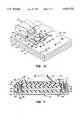
- FIG. 1is a partially sectioned, simplified side elevational view of a notebook computer having a reduced height keyboard structure embodying principles of the present invention, the computer being in an opened orientation;
- FIG. 2is an enlarged scale cross-sectional detail view of the circled keyboard area "2" in FIG. 1 and illustrates one key in its upwardly extended position, and another key in its downwardly depressed position;
- FIG. 3is a highly schematic exploded side elevational view of a multilayered signal pad portion of the keyboard structure
- FIGS. 4 and 5are enlarged scale bottom side perspective views of a key cap member respectively illustrating a scissored support portion thereof in its extended and retracted positions;
- FIG. 6is an enlarged scale simplified top side perspective view of a portion of the signal pad illustrating a representative pair of specially designed key support guide structures secured thereto and embodying principles of the present invention.
- FIG. 7is an enlarged scale cross-sectional view taken through a portion of the signal pad along line 7-7 of FIG. 6.
- the present inventionprovides a portable computer, illustratively a notebook computer 10, having incorporated therein a specially designed reduced height keyboard structure 12 embodying principles of the present invention.
- Computer 10includes a hollow rectangular base housing 14 having a top horizontal side wall 16 with an opening 18 therein; a bottom horizontal side wall 20; front and rear vertical end walls 22,24; and a pair of opposite vertical side walls 26,28.
- Lid housing 30may be upwardly pivoted to place the computer 10 in an open use orientation (FIG. 1) in which the top side 16 of the base housing 14 and the top side of the keyboard structure 12 are exposed and the display screen 32 forwardly faces the user of the computer, or downwardly pivoted to place the computer 10 in a closed storage and transport orientation (not shown) in which the lid housing extends across and covers the top side of the base housing 14 and the top side of the keyboard structure 12.
- the reduced height keyboard structure 12extends across the opening 18 in the top side wall 16 of the base housing 14 and occupies only a relatively small upper portion of the interior 36 of the base housing 14.
- the keyboard structure 12basically comprises a series of manually depressible key cap members 40 disposed generally in the top side wall opening 18 and vertically movable relative to the base housing 14, as indicated by the arrows 42 in FIG. 1, through a keystroke distance D (see FIG. 2); and a horizontally oriented multilayer key pad structure 44 that is suitable anchored within the base housing 14 in a downwardly spaced relationship with the key cap members 40.
- the multilayer signal pad structure 44is transverse to the key stroke directions 42, is of a generally conventional construction, and is shown in simplified exploded form in FIG. 3.
- Signal pad structure 44includes, from top to bottom, (1) a plastic dome sheet 46 having a spaced series of rubber key return domes 48 projecting upwardly from its top side 46a; (2) a plastic top circuit sheet 50 having a spaced series of circular, electrically conductive pads 52 disposed on its bottom side, aligned with the domes 48, and connected to surface trace circuitry (not shown) formed on the sheet 50; (3) a plastic spacer sheet 54 having a spaced series of circular openings 56 formed therein and underlying the pads 52; (4) a plastic bottom circuit sheet 58 having a spaced series of circular, electrically conductive pads 60 disposed on its top side, aligned with the sheet openings 56, and connected to surface trace circuitry (not shown) formed on the sheet 58; and (5) a metal backing sheet 62.
- the five sheet members 46, 50, 54, 58, 62
- each of the key cap members 40has a hollow, rectangular, upwardly dished molded plastic body with a top side wall 74 with a downwardly and forwardly sloping front edge portion 76, and an open bottom side 78 bounded by a rectangular, downwardly facing side wall edge periphery 78a of the key cap member.
- a scissored linkage assembly 80is secured to the bottom of each of the key cap members 40 and includes a first pair of scissor arms 82 and a second pair of scissor arms 84, with longitudinally intermediate portions of the arms 82 being pivotally connected to longitudinally intermediate portions of the arms 84 as indicated.
- First ends of the arms 82are joined by a cylindrical rod 86 pivotally anchored in tabs 88 projecting downwardly from the top key cap member wall 74, while the opposite ends of the arms 82 have outwardly projecting cylindrical pins 90 formed thereon.
- First ends of the arms 84have outwardly projecting cylindrical pins 94, while the opposite ends of the arms 84 have outwardly projecting cylindrical pins 98 slidingly received in slots 100 formed on the underside of the key cap member 40.
- Each scissored linkage assembly 80is movable relative to its associated key cap member 40 between an upwardly extended position shown in FIG. 4, and a downwardly retracted position shown in FIG. 5.
- lower side portions of the scissored linkage assemblies 80are anchored to the top side of the multilayer signal pad structure 44 in a manner placing the key cap members 40 above and in horizontal alignment with the resilient key return domes 48.
- their associated scissored linkage assemblies 80With the key cap members 40 in their upwardly extended positions, their associated scissored linkage assemblies 80 are similarly in their upwardly extended positions shown in FIG. 4, with the surfaces 104 of the linkages assemblies 80 overlying and downwardly engaging the upper ends of the resilient key return domes 48.
- key cap members 40have been representatively illustrated as being supported on the top side of the signal pad structure using scissored linkage assemblies, other means of supporting the key cap members 40 for vertical movement could be utilized if desired. Moreover, spring return means other than the rubber key return domes 48 could be utilized if desired.
- the bottom sides of the scissored linkages 80are operatively secured to a horizontally spaced series of specially designed separate key support and guide structures 110 which are separately anchored in a horizontally spaced array on the top side 46a of the multilayer signal pad structure 44 in underlying alignment with the key caps 40.
- Each of the key support and guide structures 110has a rectangular body portion with a horizontal side edge periphery 112, and a central circular opening 114 through which one of the key return domes 48 upwardly projects.
- the bottom sides of the scissored linkages 80are operatively secured to their associated key support and guide structures 110 by means of slots 92 formed on the top sides of the structures 110 and pivotally receiving the linkage pins 90, and tabs 96 formed on the top sides of the structures 110 and slidingly receiving the linkage pins 94.
- the horizontally spaced series of key support and guide structures 110which are preferably plastic moldings, are individually anchored to the top side 46a of the dome sheet 46 by means of depending legs 116 formed on the corners of each of the structures 110 and extending downwardly through circular holes 118 that transversely pass through the signal pad structure 44 from the top side 46a of the dome sheet 46 to the top side of the metal backing sheet 62.
- Lower end portions 116a of the legs 116are transversely enlarged and snap into upwardly projecting tab pairs 120,122 on the metal backing sheet 62 to anchor the key support and guide structures 110 in place on the top side of the signal pad structure 44.
- each of the key support and guide structures 110is spaced horizontally inwardly of the lower side edge periphery 78a of its associated key cap member 40. Additionally, each key support and guide structure 110 is sized to be upwardly received within the upwardly dished interior of its associated key cap member 40 when the key cap member 40 is downwardly moved from its extended position (shown on the left in FIG. 2) through its key stroke distance D to its retracted position (shown on the right in FIG. 2).
- each key support and guide structure 110permits the lower side edge periphery 78a to be moved downwardly past the top side of the structure 110 into close adjacency with the top side 46a of the dome sheet 46 when the key cap member 40 is downwardly moved through its key stroke distance D.
- the key support and guide structures 110would typically be integral portions of a plastic sheet structure positioned atop the dome sheet 46 and commonly referred to as a monoblock structure having generally the same vertical thickness T (normally in the 1-2 millimeter range) as the illustrated individual key support and guide structures 110.
- the overall height of the keyboard assembly 12would be substantially equal to the sum of the vertical thickness of the signal pad structure 44, the vertical thickness T, and the key stroke distance D.
- the top sides of the key cap members 40may be vertically positioned a distance T closer to the top side 46a of the dome sheet 46, thereby advantageously reducing the overall vertical thickness of the keyboard assembly 12 by the same distance T while maintaining the same keystroke distance D.
- This height savings of one or more millimeters across the entire horizontal extent of the keyboardmay be advantageously used to accommodate more computer circuitry or, alternatively, to permit the reduction by a distance T of the vertical thickness of the computer base housing.
Landscapes
- Engineering & Computer Science (AREA)
- Computer Hardware Design (AREA)
- Theoretical Computer Science (AREA)
- Physics & Mathematics (AREA)
- Human Computer Interaction (AREA)
- General Engineering & Computer Science (AREA)
- General Physics & Mathematics (AREA)
- Mathematical Physics (AREA)
- Input From Keyboards Or The Like (AREA)
- Push-Button Switches (AREA)
Abstract
Description
Claims (18)
Priority Applications (2)
| Application Number | Priority Date | Filing Date | Title |
|---|---|---|---|
| US08/541,460US5625532A (en) | 1995-10-10 | 1995-10-10 | Reduced height keyboard structure for a notebook computer |
| JP27001596AJP4347917B2 (en) | 1995-10-10 | 1996-10-11 | Portable computer and keyboard device thereof |
Applications Claiming Priority (1)
| Application Number | Priority Date | Filing Date | Title |
|---|---|---|---|
| US08/541,460US5625532A (en) | 1995-10-10 | 1995-10-10 | Reduced height keyboard structure for a notebook computer |
Publications (1)
| Publication Number | Publication Date |
|---|---|
| US5625532Atrue US5625532A (en) | 1997-04-29 |
Family
ID=24159691
Family Applications (1)
| Application Number | Title | Priority Date | Filing Date |
|---|---|---|---|
| US08/541,460Expired - LifetimeUS5625532A (en) | 1995-10-10 | 1995-10-10 | Reduced height keyboard structure for a notebook computer |
Country Status (2)
| Country | Link |
|---|---|
| US (1) | US5625532A (en) |
| JP (1) | JP4347917B2 (en) |
Cited By (74)
| Publication number | Priority date | Publication date | Assignee | Title |
|---|---|---|---|---|
| US5767464A (en)* | 1996-12-05 | 1998-06-16 | Texas Instruments Incorporated | Electronic device low profile keyboard switch assembly with deployed and stored actuating mechanism |
| US5813778A (en)* | 1997-03-28 | 1998-09-29 | Behavior Tech Computer Corp. | Key underboard structure of computer keyboard |
| US5842798A (en)* | 1997-12-04 | 1998-12-01 | Shin Jiuh Corp. | Computer key |
| US5847337A (en)* | 1997-07-09 | 1998-12-08 | Chen; Pao-Chin | Structure of computer keyboard key switch |
| US5850194A (en)* | 1997-12-22 | 1998-12-15 | Peripheral Technology, Inc. | Computer key |
| US5901837A (en)* | 1997-05-29 | 1999-05-11 | Matsushita Electric Industrial Co., Ltd. | Push button switch and manufacturing method of the same |
| US6068417A (en)* | 1998-03-18 | 2000-05-30 | Butler; Robert B. | Electrical key connection for expandable keyboard |
| US6127640A (en)* | 1998-07-23 | 2000-10-03 | Hon Hai Precision Ind. Co., Ltd. | Keyswitch assembly |
| US6150624A (en)* | 1998-12-31 | 2000-11-21 | Hon Hai Precision Ind. Co., Ltd. | Keyswitch device |
| US6312176B2 (en)* | 1998-04-02 | 2001-11-06 | Alps Electric Co., Ltd. | Keyboard apparatus |
| US6327144B1 (en)* | 1999-12-21 | 2001-12-04 | Hewlett-Packard Company | Computing device with improved heat dissipation |
| US6536966B1 (en) | 1998-03-18 | 2003-03-25 | Robert Brown Butler | Expandable keyboard for small computers and the like |
| US20030178293A1 (en)* | 2002-02-27 | 2003-09-25 | Minebea Co., Ltd. | Keyboard switch |
| US20030223186A1 (en)* | 2002-05-30 | 2003-12-04 | Yung-Shun Chen | Notebook computer with low-noise keyboard |
| US6781077B2 (en) | 2000-12-14 | 2004-08-24 | Think Outside, Inc. | Keyswitch and actuator structure |
| US20040200710A1 (en)* | 2003-04-14 | 2004-10-14 | Yasuo Takada | Key switch device and portable electronic device having the same |
| US20110162948A1 (en)* | 2009-06-26 | 2011-07-07 | Oki Electric Industry Co., Ltd. | Key switch structure |
| US20140091857A1 (en)* | 2012-09-28 | 2014-04-03 | Apple Inc. | Ultra Low Travel Keyboard |
| WO2014092798A1 (en)* | 2012-12-10 | 2014-06-19 | Intel Corporation | Keyboard configuration for an electronic device |
| US9064642B2 (en) | 2013-03-10 | 2015-06-23 | Apple Inc. | Rattle-free keyswitch mechanism |
| US9202355B2 (en) | 2009-09-30 | 2015-12-01 | Apple Inc. | Self adapting haptic device |
| US9317118B2 (en) | 2013-10-22 | 2016-04-19 | Apple Inc. | Touch surface for simulating materials |
| US9412533B2 (en) | 2013-05-27 | 2016-08-09 | Apple Inc. | Low travel switch assembly |
| US9449772B2 (en) | 2012-10-30 | 2016-09-20 | Apple Inc. | Low-travel key mechanisms using butterfly hinges |
| US9502193B2 (en) | 2012-10-30 | 2016-11-22 | Apple Inc. | Low-travel key mechanisms using butterfly hinges |
| US9501912B1 (en) | 2014-01-27 | 2016-11-22 | Apple Inc. | Haptic feedback device with a rotating mass of variable eccentricity |
| US9564029B2 (en) | 2014-09-02 | 2017-02-07 | Apple Inc. | Haptic notifications |
| US9608506B2 (en) | 2014-06-03 | 2017-03-28 | Apple Inc. | Linear actuator |
| US9640347B2 (en) | 2013-09-30 | 2017-05-02 | Apple Inc. | Keycaps with reduced thickness |
| US9652040B2 (en) | 2013-08-08 | 2017-05-16 | Apple Inc. | Sculpted waveforms with no or reduced unforced response |
| US9704670B2 (en) | 2013-09-30 | 2017-07-11 | Apple Inc. | Keycaps having reduced thickness |
| US9704665B2 (en) | 2014-05-19 | 2017-07-11 | Apple Inc. | Backlit keyboard including reflective component |
| US9710069B2 (en) | 2012-10-30 | 2017-07-18 | Apple Inc. | Flexible printed circuit having flex tails upon which keyboard keycaps are coupled |
| US9715978B2 (en) | 2014-05-27 | 2017-07-25 | Apple Inc. | Low travel switch assembly |
| US9779592B1 (en) | 2013-09-26 | 2017-10-03 | Apple Inc. | Geared haptic feedback element |
| US9779889B2 (en) | 2014-03-24 | 2017-10-03 | Apple Inc. | Scissor mechanism features for a keyboard |
| US9793066B1 (en) | 2014-01-31 | 2017-10-17 | Apple Inc. | Keyboard hinge mechanism |
| US9870880B2 (en) | 2014-09-30 | 2018-01-16 | Apple Inc. | Dome switch and switch housing for keyboard assembly |
| US9886093B2 (en) | 2013-09-27 | 2018-02-06 | Apple Inc. | Band with haptic actuators |
| US9908310B2 (en) | 2013-07-10 | 2018-03-06 | Apple Inc. | Electronic device with a reduced friction surface |
| US9928950B2 (en) | 2013-09-27 | 2018-03-27 | Apple Inc. | Polarized magnetic actuators for haptic response |
| US9927895B2 (en) | 2013-02-06 | 2018-03-27 | Apple Inc. | Input/output device with a dynamically adjustable appearance and function |
| US9934915B2 (en) | 2015-06-10 | 2018-04-03 | Apple Inc. | Reduced layer keyboard stack-up |
| US9971084B2 (en) | 2015-09-28 | 2018-05-15 | Apple Inc. | Illumination structure for uniform illumination of keys |
| US9997304B2 (en) | 2015-05-13 | 2018-06-12 | Apple Inc. | Uniform illumination of keys |
| US9997308B2 (en) | 2015-05-13 | 2018-06-12 | Apple Inc. | Low-travel key mechanism for an input device |
| US10013058B2 (en) | 2010-09-21 | 2018-07-03 | Apple Inc. | Touch-based user interface with haptic feedback |
| US10039080B2 (en) | 2016-03-04 | 2018-07-31 | Apple Inc. | Situationally-aware alerts |
| US10083805B2 (en) | 2015-05-13 | 2018-09-25 | Apple Inc. | Keyboard for electronic device |
| US10082880B1 (en) | 2014-08-28 | 2018-09-25 | Apple Inc. | System level features of a keyboard |
| US10115544B2 (en) | 2016-08-08 | 2018-10-30 | Apple Inc. | Singulated keyboard assemblies and methods for assembling a keyboard |
| US10120446B2 (en) | 2010-11-19 | 2018-11-06 | Apple Inc. | Haptic input device |
| US10126817B2 (en) | 2013-09-29 | 2018-11-13 | Apple Inc. | Devices and methods for creating haptic effects |
| US10128064B2 (en) | 2015-05-13 | 2018-11-13 | Apple Inc. | Keyboard assemblies having reduced thicknesses and method of forming keyboard assemblies |
| US10236760B2 (en) | 2013-09-30 | 2019-03-19 | Apple Inc. | Magnetic actuators for haptic response |
| US10268272B2 (en) | 2016-03-31 | 2019-04-23 | Apple Inc. | Dampening mechanical modes of a haptic actuator using a delay |
| US10276001B2 (en) | 2013-12-10 | 2019-04-30 | Apple Inc. | Band attachment mechanism with haptic response |
| US10353485B1 (en) | 2016-07-27 | 2019-07-16 | Apple Inc. | Multifunction input device with an embedded capacitive sensing layer |
| US10353467B2 (en) | 2015-03-06 | 2019-07-16 | Apple Inc. | Calibration of haptic devices |
| US10481691B2 (en) | 2015-04-17 | 2019-11-19 | Apple Inc. | Contracting and elongating materials for providing input and output for an electronic device |
| US10545604B2 (en) | 2014-04-21 | 2020-01-28 | Apple Inc. | Apportionment of forces for multi-touch input devices of electronic devices |
| US10566888B2 (en) | 2015-09-08 | 2020-02-18 | Apple Inc. | Linear actuators for use in electronic devices |
| US10599223B1 (en) | 2018-09-28 | 2020-03-24 | Apple Inc. | Button providing force sensing and/or haptic output |
| US10599187B2 (en)* | 2018-06-11 | 2020-03-24 | Lenovo Singapore Pte Ltd | Electronic device |
| US10622538B2 (en) | 2017-07-18 | 2020-04-14 | Apple Inc. | Techniques for providing a haptic output and sensing a haptic input using a piezoelectric body |
| US10691211B2 (en) | 2018-09-28 | 2020-06-23 | Apple Inc. | Button providing force sensing and/or haptic output |
| US10755877B1 (en) | 2016-08-29 | 2020-08-25 | Apple Inc. | Keyboard for an electronic device |
| US10775850B2 (en) | 2017-07-26 | 2020-09-15 | Apple Inc. | Computer with keyboard |
| US10796863B2 (en) | 2014-08-15 | 2020-10-06 | Apple Inc. | Fabric keyboard |
| CN114546128A (en)* | 2022-04-28 | 2022-05-27 | 深圳市晟技科技有限公司 | Dual-purpose keyboard and data connecting line adapted to same |
| US11380470B2 (en) | 2019-09-24 | 2022-07-05 | Apple Inc. | Methods to control force in reluctance actuators based on flux related parameters |
| US11500538B2 (en) | 2016-09-13 | 2022-11-15 | Apple Inc. | Keyless keyboard with force sensing and haptic feedback |
| US11809631B2 (en) | 2021-09-21 | 2023-11-07 | Apple Inc. | Reluctance haptic engine for an electronic device |
| US11977683B2 (en) | 2021-03-12 | 2024-05-07 | Apple Inc. | Modular systems configured to provide localized haptic feedback using inertial actuators |
Citations (5)
| Publication number | Priority date | Publication date | Assignee | Title |
|---|---|---|---|---|
| US5329084A (en)* | 1992-03-30 | 1994-07-12 | Brother Kogyo Kabushiki Kaisha | Keyswitch assembly |
| US5399822A (en)* | 1992-07-17 | 1995-03-21 | Brother Kogyo Kabushiki Kaisha | Keyswitch device |
| US5424516A (en)* | 1993-09-23 | 1995-06-13 | Emmons; Charles E. | Low profile pushbutton switch |
| US5466901A (en)* | 1992-06-09 | 1995-11-14 | Brother Kogyo Kabushiki Kaisha | Keyswitch assembly having mechanism for controlling touch of keys |
| US5512719A (en)* | 1993-11-05 | 1996-04-30 | Brother Kogyo Kabushiki Kaisha | Key switch having elastic portions for facilitating attachment of scissors-type support linkage to keytop and holder, and removal of keytop from linkage |
- 1995
- 1995-10-10USUS08/541,460patent/US5625532A/ennot_activeExpired - Lifetime
- 1996
- 1996-10-11JPJP27001596Apatent/JP4347917B2/ennot_activeExpired - Fee Related
Patent Citations (5)
| Publication number | Priority date | Publication date | Assignee | Title |
|---|---|---|---|---|
| US5329084A (en)* | 1992-03-30 | 1994-07-12 | Brother Kogyo Kabushiki Kaisha | Keyswitch assembly |
| US5466901A (en)* | 1992-06-09 | 1995-11-14 | Brother Kogyo Kabushiki Kaisha | Keyswitch assembly having mechanism for controlling touch of keys |
| US5399822A (en)* | 1992-07-17 | 1995-03-21 | Brother Kogyo Kabushiki Kaisha | Keyswitch device |
| US5424516A (en)* | 1993-09-23 | 1995-06-13 | Emmons; Charles E. | Low profile pushbutton switch |
| US5512719A (en)* | 1993-11-05 | 1996-04-30 | Brother Kogyo Kabushiki Kaisha | Key switch having elastic portions for facilitating attachment of scissors-type support linkage to keytop and holder, and removal of keytop from linkage |
Cited By (120)
| Publication number | Priority date | Publication date | Assignee | Title |
|---|---|---|---|---|
| US5767464A (en)* | 1996-12-05 | 1998-06-16 | Texas Instruments Incorporated | Electronic device low profile keyboard switch assembly with deployed and stored actuating mechanism |
| US5813778A (en)* | 1997-03-28 | 1998-09-29 | Behavior Tech Computer Corp. | Key underboard structure of computer keyboard |
| US5901837A (en)* | 1997-05-29 | 1999-05-11 | Matsushita Electric Industrial Co., Ltd. | Push button switch and manufacturing method of the same |
| US5847337A (en)* | 1997-07-09 | 1998-12-08 | Chen; Pao-Chin | Structure of computer keyboard key switch |
| US5842798A (en)* | 1997-12-04 | 1998-12-01 | Shin Jiuh Corp. | Computer key |
| US5850194A (en)* | 1997-12-22 | 1998-12-15 | Peripheral Technology, Inc. | Computer key |
| US6068417A (en)* | 1998-03-18 | 2000-05-30 | Butler; Robert B. | Electrical key connection for expandable keyboard |
| US6536966B1 (en) | 1998-03-18 | 2003-03-25 | Robert Brown Butler | Expandable keyboard for small computers and the like |
| US6312176B2 (en)* | 1998-04-02 | 2001-11-06 | Alps Electric Co., Ltd. | Keyboard apparatus |
| US6127640A (en)* | 1998-07-23 | 2000-10-03 | Hon Hai Precision Ind. Co., Ltd. | Keyswitch assembly |
| US6150624A (en)* | 1998-12-31 | 2000-11-21 | Hon Hai Precision Ind. Co., Ltd. | Keyswitch device |
| US6327144B1 (en)* | 1999-12-21 | 2001-12-04 | Hewlett-Packard Company | Computing device with improved heat dissipation |
| US6781077B2 (en) | 2000-12-14 | 2004-08-24 | Think Outside, Inc. | Keyswitch and actuator structure |
| US6759614B2 (en)* | 2002-02-27 | 2004-07-06 | Minebea Co., Ltd. | Keyboard switch |
| US20030178293A1 (en)* | 2002-02-27 | 2003-09-25 | Minebea Co., Ltd. | Keyboard switch |
| US20030223186A1 (en)* | 2002-05-30 | 2003-12-04 | Yung-Shun Chen | Notebook computer with low-noise keyboard |
| US20040200710A1 (en)* | 2003-04-14 | 2004-10-14 | Yasuo Takada | Key switch device and portable electronic device having the same |
| US20110162948A1 (en)* | 2009-06-26 | 2011-07-07 | Oki Electric Industry Co., Ltd. | Key switch structure |
| US8481874B2 (en)* | 2009-06-26 | 2013-07-09 | Oki Electric Industry Co., Ltd. | Key switch structure |
| US11605273B2 (en) | 2009-09-30 | 2023-03-14 | Apple Inc. | Self-adapting electronic device |
| US11043088B2 (en) | 2009-09-30 | 2021-06-22 | Apple Inc. | Self adapting haptic device |
| US9934661B2 (en) | 2009-09-30 | 2018-04-03 | Apple Inc. | Self adapting haptic device |
| US9640048B2 (en) | 2009-09-30 | 2017-05-02 | Apple Inc. | Self adapting haptic device |
| US9202355B2 (en) | 2009-09-30 | 2015-12-01 | Apple Inc. | Self adapting haptic device |
| US10475300B2 (en) | 2009-09-30 | 2019-11-12 | Apple Inc. | Self adapting haptic device |
| US12094328B2 (en) | 2009-09-30 | 2024-09-17 | Apple Inc. | Device having a camera used to detect visual cues that activate a function of the device |
| US10013058B2 (en) | 2010-09-21 | 2018-07-03 | Apple Inc. | Touch-based user interface with haptic feedback |
| US10120446B2 (en) | 2010-11-19 | 2018-11-06 | Apple Inc. | Haptic input device |
| US9997306B2 (en) | 2012-09-28 | 2018-06-12 | Apple Inc. | Ultra low travel keyboard |
| US9178509B2 (en)* | 2012-09-28 | 2015-11-03 | Apple Inc. | Ultra low travel keyboard |
| US9911553B2 (en) | 2012-09-28 | 2018-03-06 | Apple Inc. | Ultra low travel keyboard |
| US20140091857A1 (en)* | 2012-09-28 | 2014-04-03 | Apple Inc. | Ultra Low Travel Keyboard |
| US9761389B2 (en) | 2012-10-30 | 2017-09-12 | Apple Inc. | Low-travel key mechanisms with butterfly hinges |
| US10699856B2 (en) | 2012-10-30 | 2020-06-30 | Apple Inc. | Low-travel key mechanisms using butterfly hinges |
| US10254851B2 (en) | 2012-10-30 | 2019-04-09 | Apple Inc. | Keyboard key employing a capacitive sensor and dome |
| US10211008B2 (en) | 2012-10-30 | 2019-02-19 | Apple Inc. | Low-travel key mechanisms using butterfly hinges |
| US9710069B2 (en) | 2012-10-30 | 2017-07-18 | Apple Inc. | Flexible printed circuit having flex tails upon which keyboard keycaps are coupled |
| US9449772B2 (en) | 2012-10-30 | 2016-09-20 | Apple Inc. | Low-travel key mechanisms using butterfly hinges |
| US9502193B2 (en) | 2012-10-30 | 2016-11-22 | Apple Inc. | Low-travel key mechanisms using butterfly hinges |
| US9916945B2 (en) | 2012-10-30 | 2018-03-13 | Apple Inc. | Low-travel key mechanisms using butterfly hinges |
| US11023081B2 (en) | 2012-10-30 | 2021-06-01 | Apple Inc. | Multi-functional keyboard assemblies |
| CN104126162B (en)* | 2012-12-10 | 2017-03-15 | 英特尔公司 | Keyboard for electronic equipment is configured |
| CN104126162A (en)* | 2012-12-10 | 2014-10-29 | 英特尔公司 | Keyboard configuration for an electronic device |
| WO2014092798A1 (en)* | 2012-12-10 | 2014-06-19 | Intel Corporation | Keyboard configuration for an electronic device |
| US9465413B2 (en) | 2012-12-10 | 2016-10-11 | Intel Corporation | Keyboard configuration for an electronic device |
| US9927895B2 (en) | 2013-02-06 | 2018-03-27 | Apple Inc. | Input/output device with a dynamically adjustable appearance and function |
| US10114489B2 (en) | 2013-02-06 | 2018-10-30 | Apple Inc. | Input/output device with a dynamically adjustable appearance and function |
| US9064642B2 (en) | 2013-03-10 | 2015-06-23 | Apple Inc. | Rattle-free keyswitch mechanism |
| US10262814B2 (en) | 2013-05-27 | 2019-04-16 | Apple Inc. | Low travel switch assembly |
| US9412533B2 (en) | 2013-05-27 | 2016-08-09 | Apple Inc. | Low travel switch assembly |
| US10556408B2 (en) | 2013-07-10 | 2020-02-11 | Apple Inc. | Electronic device with a reduced friction surface |
| US9908310B2 (en) | 2013-07-10 | 2018-03-06 | Apple Inc. | Electronic device with a reduced friction surface |
| US9652040B2 (en) | 2013-08-08 | 2017-05-16 | Apple Inc. | Sculpted waveforms with no or reduced unforced response |
| US9779592B1 (en) | 2013-09-26 | 2017-10-03 | Apple Inc. | Geared haptic feedback element |
| US9928950B2 (en) | 2013-09-27 | 2018-03-27 | Apple Inc. | Polarized magnetic actuators for haptic response |
| US9886093B2 (en) | 2013-09-27 | 2018-02-06 | Apple Inc. | Band with haptic actuators |
| US10126817B2 (en) | 2013-09-29 | 2018-11-13 | Apple Inc. | Devices and methods for creating haptic effects |
| US10224157B2 (en) | 2013-09-30 | 2019-03-05 | Apple Inc. | Keycaps having reduced thickness |
| US10002727B2 (en) | 2013-09-30 | 2018-06-19 | Apple Inc. | Keycaps with reduced thickness |
| US9704670B2 (en) | 2013-09-30 | 2017-07-11 | Apple Inc. | Keycaps having reduced thickness |
| US10651716B2 (en) | 2013-09-30 | 2020-05-12 | Apple Inc. | Magnetic actuators for haptic response |
| US10236760B2 (en) | 2013-09-30 | 2019-03-19 | Apple Inc. | Magnetic actuators for haptic response |
| US9640347B2 (en) | 2013-09-30 | 2017-05-02 | Apple Inc. | Keycaps with reduced thickness |
| US10804051B2 (en) | 2013-09-30 | 2020-10-13 | Apple Inc. | Keycaps having reduced thickness |
| US11699558B2 (en) | 2013-09-30 | 2023-07-11 | Apple Inc. | Keycaps having reduced thickness |
| US9317118B2 (en) | 2013-10-22 | 2016-04-19 | Apple Inc. | Touch surface for simulating materials |
| US10459521B2 (en) | 2013-10-22 | 2019-10-29 | Apple Inc. | Touch surface for simulating materials |
| US10276001B2 (en) | 2013-12-10 | 2019-04-30 | Apple Inc. | Band attachment mechanism with haptic response |
| US9501912B1 (en) | 2014-01-27 | 2016-11-22 | Apple Inc. | Haptic feedback device with a rotating mass of variable eccentricity |
| US9793066B1 (en) | 2014-01-31 | 2017-10-17 | Apple Inc. | Keyboard hinge mechanism |
| US9779889B2 (en) | 2014-03-24 | 2017-10-03 | Apple Inc. | Scissor mechanism features for a keyboard |
| US10545604B2 (en) | 2014-04-21 | 2020-01-28 | Apple Inc. | Apportionment of forces for multi-touch input devices of electronic devices |
| US9704665B2 (en) | 2014-05-19 | 2017-07-11 | Apple Inc. | Backlit keyboard including reflective component |
| US9715978B2 (en) | 2014-05-27 | 2017-07-25 | Apple Inc. | Low travel switch assembly |
| US10069392B2 (en) | 2014-06-03 | 2018-09-04 | Apple Inc. | Linear vibrator with enclosed mass assembly structure |
| US9608506B2 (en) | 2014-06-03 | 2017-03-28 | Apple Inc. | Linear actuator |
| US10796863B2 (en) | 2014-08-15 | 2020-10-06 | Apple Inc. | Fabric keyboard |
| US10082880B1 (en) | 2014-08-28 | 2018-09-25 | Apple Inc. | System level features of a keyboard |
| US9564029B2 (en) | 2014-09-02 | 2017-02-07 | Apple Inc. | Haptic notifications |
| US9830782B2 (en) | 2014-09-02 | 2017-11-28 | Apple Inc. | Haptic notifications |
| US10490035B2 (en) | 2014-09-02 | 2019-11-26 | Apple Inc. | Haptic notifications |
| US10192696B2 (en) | 2014-09-30 | 2019-01-29 | Apple Inc. | Light-emitting assembly for keyboard |
| US10879019B2 (en) | 2014-09-30 | 2020-12-29 | Apple Inc. | Light-emitting assembly for keyboard |
| US10134539B2 (en) | 2014-09-30 | 2018-11-20 | Apple Inc. | Venting system and shield for keyboard |
| US9870880B2 (en) | 2014-09-30 | 2018-01-16 | Apple Inc. | Dome switch and switch housing for keyboard assembly |
| US10128061B2 (en) | 2014-09-30 | 2018-11-13 | Apple Inc. | Key and switch housing for keyboard assembly |
| US10353467B2 (en) | 2015-03-06 | 2019-07-16 | Apple Inc. | Calibration of haptic devices |
| US10481691B2 (en) | 2015-04-17 | 2019-11-19 | Apple Inc. | Contracting and elongating materials for providing input and output for an electronic device |
| US11402911B2 (en) | 2015-04-17 | 2022-08-02 | Apple Inc. | Contracting and elongating materials for providing input and output for an electronic device |
| US10468211B2 (en) | 2015-05-13 | 2019-11-05 | Apple Inc. | Illuminated low-travel key mechanism for a keyboard |
| US9997304B2 (en) | 2015-05-13 | 2018-06-12 | Apple Inc. | Uniform illumination of keys |
| US10424446B2 (en) | 2015-05-13 | 2019-09-24 | Apple Inc. | Keyboard assemblies having reduced thickness and method of forming keyboard assemblies |
| US9997308B2 (en) | 2015-05-13 | 2018-06-12 | Apple Inc. | Low-travel key mechanism for an input device |
| US10083805B2 (en) | 2015-05-13 | 2018-09-25 | Apple Inc. | Keyboard for electronic device |
| US10083806B2 (en) | 2015-05-13 | 2018-09-25 | Apple Inc. | Keyboard for electronic device |
| US10128064B2 (en) | 2015-05-13 | 2018-11-13 | Apple Inc. | Keyboard assemblies having reduced thicknesses and method of forming keyboard assemblies |
| US9934915B2 (en) | 2015-06-10 | 2018-04-03 | Apple Inc. | Reduced layer keyboard stack-up |
| US10566888B2 (en) | 2015-09-08 | 2020-02-18 | Apple Inc. | Linear actuators for use in electronic devices |
| US10310167B2 (en) | 2015-09-28 | 2019-06-04 | Apple Inc. | Illumination structure for uniform illumination of keys |
| US9971084B2 (en) | 2015-09-28 | 2018-05-15 | Apple Inc. | Illumination structure for uniform illumination of keys |
| US10039080B2 (en) | 2016-03-04 | 2018-07-31 | Apple Inc. | Situationally-aware alerts |
| US10609677B2 (en) | 2016-03-04 | 2020-03-31 | Apple Inc. | Situationally-aware alerts |
| US10268272B2 (en) | 2016-03-31 | 2019-04-23 | Apple Inc. | Dampening mechanical modes of a haptic actuator using a delay |
| US10809805B2 (en) | 2016-03-31 | 2020-10-20 | Apple Inc. | Dampening mechanical modes of a haptic actuator using a delay |
| US10353485B1 (en) | 2016-07-27 | 2019-07-16 | Apple Inc. | Multifunction input device with an embedded capacitive sensing layer |
| US10115544B2 (en) | 2016-08-08 | 2018-10-30 | Apple Inc. | Singulated keyboard assemblies and methods for assembling a keyboard |
| US11282659B2 (en) | 2016-08-08 | 2022-03-22 | Apple Inc. | Singulated keyboard assemblies and methods for assembling a keyboard |
| US10755877B1 (en) | 2016-08-29 | 2020-08-25 | Apple Inc. | Keyboard for an electronic device |
| US11500538B2 (en) | 2016-09-13 | 2022-11-15 | Apple Inc. | Keyless keyboard with force sensing and haptic feedback |
| US10622538B2 (en) | 2017-07-18 | 2020-04-14 | Apple Inc. | Techniques for providing a haptic output and sensing a haptic input using a piezoelectric body |
| US10775850B2 (en) | 2017-07-26 | 2020-09-15 | Apple Inc. | Computer with keyboard |
| US10599187B2 (en)* | 2018-06-11 | 2020-03-24 | Lenovo Singapore Pte Ltd | Electronic device |
| US10691211B2 (en) | 2018-09-28 | 2020-06-23 | Apple Inc. | Button providing force sensing and/or haptic output |
| US10599223B1 (en) | 2018-09-28 | 2020-03-24 | Apple Inc. | Button providing force sensing and/or haptic output |
| US11380470B2 (en) | 2019-09-24 | 2022-07-05 | Apple Inc. | Methods to control force in reluctance actuators based on flux related parameters |
| US11763971B2 (en) | 2019-09-24 | 2023-09-19 | Apple Inc. | Methods to control force in reluctance actuators based on flux related parameters |
| US11977683B2 (en) | 2021-03-12 | 2024-05-07 | Apple Inc. | Modular systems configured to provide localized haptic feedback using inertial actuators |
| US11809631B2 (en) | 2021-09-21 | 2023-11-07 | Apple Inc. | Reluctance haptic engine for an electronic device |
| CN114546128B (en)* | 2022-04-28 | 2022-06-28 | 深圳市晟技科技有限公司 | A dual-purpose keyboard and its adapted data connection cable |
| CN114546128A (en)* | 2022-04-28 | 2022-05-27 | 深圳市晟技科技有限公司 | Dual-purpose keyboard and data connecting line adapted to same |
Also Published As
| Publication number | Publication date |
|---|---|
| JP4347917B2 (en) | 2009-10-21 |
| JPH09128119A (en) | 1997-05-16 |
Similar Documents
| Publication | Publication Date | Title |
|---|---|---|
| US5625532A (en) | Reduced height keyboard structure for a notebook computer | |
| US5587875A (en) | Collapsible notebook computer keyboard structure with horizontally and downwardly shiftable key return domes | |
| US5590020A (en) | Collapsible notebook computer keyboard structure with resiliently deflectable key cap skirts | |
| US5654872A (en) | Collapsible keyboard structure for a notebook computer | |
| US5602715A (en) | Collapsible keyboard structure for a notebook computer, responsive to opening and closing of the computer's lid via relatively shiftable key support member and shift member | |
| US5621610A (en) | Collapsible computer keyboard structure with associated collapsible pointing stick | |
| CA2152866C (en) | Compact notebook computer having a foldable and collapsible keyboard structure | |
| KR100322143B1 (en) | Keyboard device and personal computer using same | |
| US5268545A (en) | Low profile tactile keyswitch | |
| US5457297A (en) | Computer keyboard key switch | |
| US5278371A (en) | Keyswitch assembly with support mechanism coupled to support plate beneath printed circuit board | |
| US5490037A (en) | Flexing keyboard structure for a notebook computer | |
| US7034718B2 (en) | Keyboard with elevated keys | |
| US5677826A (en) | Double spring collapsible keyboard structure for a notebook computer, responsive to opening and closing of the computer's lid via relatively shiftable key support structure and shift member | |
| US6137676A (en) | Collapsible keyboard mechanism with integrated LCD display | |
| EP1139360B1 (en) | Key switch device | |
| SK25895A3 (en) | Keyboard with full movable self-lifting keys | |
| US11120956B1 (en) | Keyboard device | |
| US5786806A (en) | Collapsible keyboard/pointing stick structure | |
| CN215527544U (en) | Long key device of keyboard | |
| JP3063410B2 (en) | Key switch device | |
| US20090120774A1 (en) | Dynamically self-stabilizing elastic keyswitch | |
| CN222672874U (en) | Balance bar key cap structure capable of reducing noise | |
| KR102788030B1 (en) | Keyboard assembly, device framework, and electronic device | |
| JP3593720B2 (en) | Key switch device |
Legal Events
| Date | Code | Title | Description |
|---|---|---|---|
| AS | Assignment | Owner name:COMPAQ COMPUTER CORPORATION, TEXAS Free format text:ASSIGNMENT OF ASSIGNORS INTEREST;ASSIGNOR:SELLERS, CHARLES A.;REEL/FRAME:007704/0268 Effective date:19950912 | |
| STCF | Information on status: patent grant | Free format text:PATENTED CASE | |
| FEPP | Fee payment procedure | Free format text:PAYOR NUMBER ASSIGNED (ORIGINAL EVENT CODE: ASPN); ENTITY STATUS OF PATENT OWNER: LARGE ENTITY | |
| FPAY | Fee payment | Year of fee payment:4 | |
| AS | Assignment | Owner name:COMPAQ INFORMATION TECHNOLOGIES GROUP, L.P., TEXAS Free format text:ASSIGNMENT OF ASSIGNORS INTEREST;ASSIGNOR:COMPAQ COMPUTER CORPORATION;REEL/FRAME:012418/0222 Effective date:20010620 | |
| AS | Assignment | Owner name:HEWLETT-PACKARD DEVELOPMENT COMPANY, L.P., TEXAS Free format text:CHANGE OF NAME;ASSIGNOR:COMPAQ INFORMATION TECHNOLOGIES GROUP, LP;REEL/FRAME:015000/0305 Effective date:20021001 | |
| FPAY | Fee payment | Year of fee payment:8 | |
| FPAY | Fee payment | Year of fee payment:12 | |
| FEPP | Fee payment procedure | Free format text:PAYER NUMBER DE-ASSIGNED (ORIGINAL EVENT CODE: RMPN); ENTITY STATUS OF PATENT OWNER: LARGE ENTITY Free format text:PAYOR NUMBER ASSIGNED (ORIGINAL EVENT CODE: ASPN); ENTITY STATUS OF PATENT OWNER: LARGE ENTITY |