US5625140A - Acoustic analysis of gas mixtures - Google Patents
Acoustic analysis of gas mixturesDownload PDFInfo
- Publication number
- US5625140A US5625140AUS08/570,906US57090695AUS5625140AUS 5625140 AUS5625140 AUS 5625140AUS 57090695 AUS57090695 AUS 57090695AUS 5625140 AUS5625140 AUS 5625140A
- Authority
- US
- United States
- Prior art keywords
- gas
- cell
- acoustic
- transducer
- conduit
- Prior art date
- Legal status (The legal status is an assumption and is not a legal conclusion. Google has not performed a legal analysis and makes no representation as to the accuracy of the status listed.)
- Expired - Lifetime
Links
- 239000000203mixtureSubstances0.000titleclaimsabstractdescription49
- 238000004458analytical methodMethods0.000titleabstractdescription10
- 229910052751metalInorganic materials0.000claimsabstractdescription11
- 239000002184metalSubstances0.000claimsabstractdescription11
- 150000001875compoundsChemical class0.000claimsdescription6
- 230000005540biological transmissionEffects0.000claimsdescription2
- 239000011358absorbing materialSubstances0.000claims4
- 230000035939shockEffects0.000claims1
- 210000004027cellAnatomy0.000abstractdescription76
- 210000005056cell bodyAnatomy0.000abstractdescription8
- 239000007789gasSubstances0.000description103
- 239000000463materialSubstances0.000description42
- 239000000945fillerSubstances0.000description14
- 238000000034methodMethods0.000description13
- 238000005259measurementMethods0.000description10
- 230000008569processEffects0.000description8
- 229910001220stainless steelInorganic materials0.000description8
- 238000004868gas analysisMethods0.000description7
- 238000012544monitoring processMethods0.000description7
- 239000010935stainless steelSubstances0.000description7
- XKRFYHLGVUSROY-UHFFFAOYSA-NArgonChemical compound[Ar]XKRFYHLGVUSROY-UHFFFAOYSA-N0.000description6
- 239000003795chemical substances by applicationSubstances0.000description6
- 239000002019doping agentSubstances0.000description6
- 229910052451lead zirconate titanateInorganic materials0.000description6
- 238000002604ultrasonographyMethods0.000description6
- 239000004927claySubstances0.000description5
- 230000008878couplingEffects0.000description5
- 238000010168coupling processMethods0.000description5
- 238000005859coupling reactionMethods0.000description5
- VYPSYNLAJGMNEJ-UHFFFAOYSA-NSilicium dioxideChemical compoundO=[Si]=OVYPSYNLAJGMNEJ-UHFFFAOYSA-N0.000description4
- 238000010521absorption reactionMethods0.000description4
- QVGXLLKOCUKJST-UHFFFAOYSA-Natomic oxygenChemical compound[O]QVGXLLKOCUKJST-UHFFFAOYSA-N0.000description4
- 238000005229chemical vapour depositionMethods0.000description4
- 239000013536elastomeric materialSubstances0.000description4
- 238000002955isolationMethods0.000description4
- HFGPZNIAWCZYJU-UHFFFAOYSA-Nlead zirconate titanateChemical compound[O-2].[O-2].[O-2].[O-2].[O-2].[Ti+4].[Zr+4].[Pb+2]HFGPZNIAWCZYJU-UHFFFAOYSA-N0.000description4
- 239000001301oxygenSubstances0.000description4
- 229910052760oxygenInorganic materials0.000description4
- XLYOFNOQVPJJNP-UHFFFAOYSA-NwaterSubstancesOXLYOFNOQVPJJNP-UHFFFAOYSA-N0.000description4
- PEDCQBHIVMGVHV-UHFFFAOYSA-NGlycerineChemical compoundOCC(O)COPEDCQBHIVMGVHV-UHFFFAOYSA-N0.000description3
- 229910052786argonInorganic materials0.000description3
- 239000000470constituentSubstances0.000description3
- 239000001307heliumSubstances0.000description3
- 229910052734heliumInorganic materials0.000description3
- SWQJXJOGLNCZEY-UHFFFAOYSA-Nhelium atomChemical compound[He]SWQJXJOGLNCZEY-UHFFFAOYSA-N0.000description3
- 230000013011matingEffects0.000description3
- 238000012545processingMethods0.000description3
- IEXRMSFAVATTJX-UHFFFAOYSA-NtetrachlorogermaneChemical compoundCl[Ge](Cl)(Cl)ClIEXRMSFAVATTJX-UHFFFAOYSA-N0.000description3
- 229920004943Delrin®Polymers0.000description2
- 229910006113GeCl4Inorganic materials0.000description2
- PXHVJJICTQNCMI-UHFFFAOYSA-NNickelChemical compound[Ni]PXHVJJICTQNCMI-UHFFFAOYSA-N0.000description2
- 229910003910SiCl4Inorganic materials0.000description2
- 238000006243chemical reactionMethods0.000description2
- 238000004891communicationMethods0.000description2
- 239000013078crystalSubstances0.000description2
- 238000000151depositionMethods0.000description2
- 230000008021depositionEffects0.000description2
- 238000009826distributionMethods0.000description2
- 230000000694effectsEffects0.000description2
- 229920001971elastomerPolymers0.000description2
- 239000000806elastomerSubstances0.000description2
- 239000000835fiberSubstances0.000description2
- 239000012530fluidSubstances0.000description2
- 239000011521glassSubstances0.000description2
- 239000011344liquid materialSubstances0.000description2
- 238000004519manufacturing processMethods0.000description2
- 230000037361pathwayEffects0.000description2
- 230000001902propagating effectEffects0.000description2
- 230000004044responseEffects0.000description2
- 239000000377silicon dioxideSubstances0.000description2
- FDNAPBUWERUEDA-UHFFFAOYSA-Nsilicon tetrachlorideChemical compoundCl[Si](Cl)(Cl)ClFDNAPBUWERUEDA-UHFFFAOYSA-N0.000description2
- 239000011343solid materialSubstances0.000description2
- 238000011144upstream manufacturingMethods0.000description2
- 229910000619316 stainless steelInorganic materials0.000description1
- VXEGSRKPIUDPQT-UHFFFAOYSA-N4-[4-(4-methoxyphenyl)piperazin-1-yl]anilineChemical compoundC1=CC(OC)=CC=C1N1CCN(C=2C=CC(N)=CC=2)CC1VXEGSRKPIUDPQT-UHFFFAOYSA-N0.000description1
- LFQSCWFLJHTTHZ-UHFFFAOYSA-NEthanolChemical compoundCCOLFQSCWFLJHTTHZ-UHFFFAOYSA-N0.000description1
- 229920004142LEXAN™Polymers0.000description1
- ZOKXTWBITQBERF-UHFFFAOYSA-NMolybdenumChemical compound[Mo]ZOKXTWBITQBERF-UHFFFAOYSA-N0.000description1
- 229920006102Zytel®Polymers0.000description1
- 239000000853adhesiveSubstances0.000description1
- 230000001070adhesive effectEffects0.000description1
- 230000002238attenuated effectEffects0.000description1
- 230000015572biosynthetic processEffects0.000description1
- 239000012159carrier gasSubstances0.000description1
- 230000015556catabolic processEffects0.000description1
- 210000003850cellular structureAnatomy0.000description1
- 238000005253claddingMethods0.000description1
- 230000007423decreaseEffects0.000description1
- 238000006731degradation reactionMethods0.000description1
- 230000001419dependent effectEffects0.000description1
- 238000010586diagramMethods0.000description1
- 239000003822epoxy resinSubstances0.000description1
- 230000005284excitationEffects0.000description1
- 239000006260foamSubstances0.000description1
- 238000009472formulationMethods0.000description1
- 239000008246gaseous mixtureSubstances0.000description1
- 230000007274generation of a signal involved in cell-cell signalingEffects0.000description1
- 210000004907glandAnatomy0.000description1
- 238000010348incorporationMethods0.000description1
- 239000011261inert gasSubstances0.000description1
- 239000002480mineral oilSubstances0.000description1
- 235000010446mineral oilNutrition0.000description1
- 238000012986modificationMethods0.000description1
- 230000004048modificationEffects0.000description1
- 229910052750molybdenumInorganic materials0.000description1
- 239000011733molybdenumSubstances0.000description1
- 229910052759nickelInorganic materials0.000description1
- 230000001473noxious effectEffects0.000description1
- 239000013307optical fiberSubstances0.000description1
- 229920000647polyepoxidePolymers0.000description1
- 239000002243precursorSubstances0.000description1
- 230000001737promoting effectEffects0.000description1
- 239000012495reaction gasSubstances0.000description1
- 230000009467reductionEffects0.000description1
- 239000012858resilient materialSubstances0.000description1
- 239000011347resinSubstances0.000description1
- 229920005989resinPolymers0.000description1
- 238000007789sealingMethods0.000description1
- 239000004065semiconductorSubstances0.000description1
- 230000035945sensitivityEffects0.000description1
- 238000000926separation methodMethods0.000description1
- 239000005049silicon tetrachlorideSubstances0.000description1
- 229920002379silicone rubberPolymers0.000description1
- 239000007787solidSubstances0.000description1
- 229920003051synthetic elastomerPolymers0.000description1
- 230000026676system processEffects0.000description1
- XCZXGTMEAKBVPV-UHFFFAOYSA-NtrimethylgalliumChemical compoundC[Ga](C)CXCZXGTMEAKBVPV-UHFFFAOYSA-N0.000description1
- IBEFSUTVZWZJEL-UHFFFAOYSA-NtrimethylindiumChemical compoundC[In](C)CIBEFSUTVZWZJEL-UHFFFAOYSA-N0.000description1
- 238000005019vapor deposition processMethods0.000description1
Images


Classifications
- G—PHYSICS
- G01—MEASURING; TESTING
- G01N—INVESTIGATING OR ANALYSING MATERIALS BY DETERMINING THEIR CHEMICAL OR PHYSICAL PROPERTIES
- G01N29/00—Investigating or analysing materials by the use of ultrasonic, sonic or infrasonic waves; Visualisation of the interior of objects by transmitting ultrasonic or sonic waves through the object
- G01N29/22—Details, e.g. general constructional or apparatus details
- G—PHYSICS
- G01—MEASURING; TESTING
- G01N—INVESTIGATING OR ANALYSING MATERIALS BY DETERMINING THEIR CHEMICAL OR PHYSICAL PROPERTIES
- G01N29/00—Investigating or analysing materials by the use of ultrasonic, sonic or infrasonic waves; Visualisation of the interior of objects by transmitting ultrasonic or sonic waves through the object
- G01N29/02—Analysing fluids
- G01N29/024—Analysing fluids by measuring propagation velocity or propagation time of acoustic waves
- G—PHYSICS
- G01—MEASURING; TESTING
- G01N—INVESTIGATING OR ANALYSING MATERIALS BY DETERMINING THEIR CHEMICAL OR PHYSICAL PROPERTIES
- G01N29/00—Investigating or analysing materials by the use of ultrasonic, sonic or infrasonic waves; Visualisation of the interior of objects by transmitting ultrasonic or sonic waves through the object
- G01N29/22—Details, e.g. general constructional or apparatus details
- G01N29/222—Constructional or flow details for analysing fluids
- G—PHYSICS
- G01—MEASURING; TESTING
- G01N—INVESTIGATING OR ANALYSING MATERIALS BY DETERMINING THEIR CHEMICAL OR PHYSICAL PROPERTIES
- G01N2291/00—Indexing codes associated with group G01N29/00
- G01N2291/02—Indexing codes associated with the analysed material
- G01N2291/021—Gases
- G—PHYSICS
- G01—MEASURING; TESTING
- G01N—INVESTIGATING OR ANALYSING MATERIALS BY DETERMINING THEIR CHEMICAL OR PHYSICAL PROPERTIES
- G01N2291/00—Indexing codes associated with group G01N29/00
- G01N2291/02—Indexing codes associated with the analysed material
- G01N2291/028—Material parameters
- G01N2291/02809—Concentration of a compound, e.g. measured by a surface mass change
- G—PHYSICS
- G01—MEASURING; TESTING
- G01N—INVESTIGATING OR ANALYSING MATERIALS BY DETERMINING THEIR CHEMICAL OR PHYSICAL PROPERTIES
- G01N2291/00—Indexing codes associated with group G01N29/00
- G01N2291/02—Indexing codes associated with the analysed material
- G01N2291/028—Material parameters
- G01N2291/02836—Flow rate, liquid level
Definitions
- the inventionrelates to the field of acoustic gas monitoring and, more particularly, to the in-line monitoring and control of the composition of gas mixtures.
- CVDchemical vapor deposition
- formation of semiconductor materials and optical fiber performsoften involves incorporation of dopant materials in very small concentrations.
- the dopant materialis supplied by a dopant precursor gas which is mixed with other deposition gases in a reaction chamber. Because of the low concentration used in the vapor deposition process, the dopant gas is usually mixed with a carrier gas to ensure an even distribution of dopant within the reaction chamber.
- the career gasmust deliver a consistent quantity of the dopant gas. In-line gas monitoring is often used to ensure this consistent delivery.
- Acoustic monitoring of gasescan employ ultrasound, i.e., sound waves having a frequency ranging from a few kHz to 10 MHz. Acoustic techniques have been extensively used for gas flow monitoring. More recently, efforts have turned to developing acoustic cells and processes which can determine the concentration of a component of a binary gas mixture. In general, acoustic concentration analysis of a gas mixture is performed by measuring the speed with which sound waves propagate through a gas mixture. Because the speed at which the sound waves travel through a gas is related to molecular weight, the concentration of a component of a gas mixture can be accurately determined.
- V sthe velocity of sound
- ⁇is the specific heat capacity ratio (C p /C v )
- Ris the universal gas constant (8.3143 J/mol K.)
- Tis the absolute temperature in degrees Kelvin
- Mis the molecular weight of the gas in kg.
- ⁇is the average specific heat capacity ratio given by: ##EQU3##
- Mis the mean molecular weight of the binary gas mixture given by:
- xis the mole fraction of a second gas and M 1 and M 2 are the respective molecular weights of the first and second gases.
- V sis in units of meter/second.
- ultrasonic pulsesare generated by an ultrasonic transducer.
- the transduceris composed of a piezoelectric material, such as lead zirconate titanate, and is positioned opposite a second transducer.
- the transit time of sonic pulses between the transducersis measured and used to yield the sound velocity. From the velocity, the composition of the binary mixture is determined.
- metal gasketsare employed for gas sealing. Because these metal gaskets permit acoustic coupling through the body of the cell, each transducer is supported on an array of mounting pins to minimize acoustic coupling between the transducer and the cell body.
- the cell of the U.K. applicationreduces acoustic coupling, there is still sufficient extraneous noise to interfere with the acoustic measurement process. The result is a loss of sensitivity of the cell. Additionally, the cell of the U.K. application operates using ultrasonic frequencies on the order of one megahertz. In general, as sound frequency increases, the attenuation of sound waves also increases. At frequencies in the megahertz range, attenuation of sound in the gas being analyzed is a problem, particularly when attempting to measure high sound absorptive gases, which absorb ultrasound in higher ultrasonic frequency ranges. Because the cell of the U.K. application has a short path length, higher frequencies are required to attain the resolution needed to detect the arriving pulse.
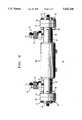
- FIG. 1is a partial cross-section of the acoustic analysis gas cell 10 described in Cadet et al.
- the transducer 80is placed opposite the end 22 of conduit 20. Gas flows through a gas port 70, through a passage 35 and a cylindrical gap 39 and into the conduit end 22. The gas passes transducer 80 as it flows into the conduit end 22. As illustrated in FIG. 1, Cadet et al. couple the transducer 80 to a layer of acoustic isolation material 82.
- the acoustic isolation material 82is an elastomeric material such as a silicone elastomer.
- Cadet et al.also propose inserting a layer of this elastomeric material 83 between the transducer 80 and the gaseous mixture to be analyzed.
- the acoustic isolation provided by Cadet et al.produces a signal-to-noise ratio of at least 4:1.
- the elastomeric materialsince the elastomeric material is exposed to the gas being analyzed, the elastomeric material must withstand exposure to corrosive gas environments. Since elastomers typically degrade when subjected to corrosive gases, the solution offered by Cadet et al. may not be suited for acoustic analysis of all gas mixtures.
- U.S. Pat. No. 5,060,506a method and apparatus are disclosed for monitoring the ratio of gases in a two-gas mixture using ultrasound.
- the transmitter used to generate the ultrasonic pulsesis excited with a signal having a plurality of successive bursts, each of which includes a preselected number of excitation pulses at the resonant frequency.
- the initial pulse in each burstis separated from the final pulse in the preceding burst by a quiescent time period of sufficient duration to assure dissipation of transients so that standing waves do not form.
- the present inventionis directed to an acoustic gas composition analysis cell in which the transducers are disposed in stainless steel housings which provide vacuum compatibility and that are resistant to corrosive gas environments.
- a transducerIn the cells of the present invention, a transducer generates vibration which is transmitted through the stainless steel housing and into a gas flowing through the cell. Since the stainless steel housings introduce noise into the signal being monitored, it is necessary to reduce the noise in the signal produced by the cell of the present invention.
- the cellis provided with a sleeve assembly that reduces the noise in the signal, thereby increasing the signal-to-noise ratio to at least about 4:1.
- the sleeve assemblyis formed around the cell.
- the sleeve assemblyhas an outer sleeve and a filler material interposed between the sleeve and the cell body.
- the sleeveis an elastomer.
- the filler materialis any material which will acoustically couple to the cell.
- the filler materialis physically in contact with the cell. That is, it is advantageous if there is no material such as a gas, interposed between the filler material and the cell. Suitable materials include both solid material such as modeling compounds and liquid materials such as water or alcohol.
- the filler materialis inert with respect to the elastomeric sleeve and the metal body of the cell.
- Solid filler materialsare preferred because the sound absorption characteristics of these materials varies less with temperature.
- both modeling compounds and waterare suitable fillers at room temperature. But at temperatures above about 45° C., water is no longer able to absorb sound adequately from the cell. This is because the attenuation of ultrasound in water is due to sound absorption from frictional effects. The absorption coefficient (db/mm) decreases with increasing temperature. At these higher temperatures, the modeling compounds absorb sound effectively. Since acoustic cells of the present invention typically operate at temperatures of about 20° C. to about 70° C., filler materials that absorb sound effectively within this range are required.
- the transducers employed in the acoustic celloperate in the kilohertz range, reducing attenuation in the gas mixture being analyzed.
- the cell bodyemploys vacuum seals which permit the use of the cell in line with vacuum equipment.
- FIG. 1is an enlarged side view in partial cross-section of a transducer and housing assembled in a prior art acoustic analysis gas cell.
- FIG. 2is a view of an acoustic gas analysis cell according to the present invention.
- FIG. 3is a side view in partial cross section of an acoustic gas analysis cell of the present invention.
- FIG. 4is an enlarged side view in partial cross-section of a transducer and housing assembled in the acoustic gas analysis cell of the present invention, illustrating gas flow into the cell.
- FIG. 5is a schematic block diagram of the signal generating and data processing circuit used with the acoustic gas analysis cell of FIG. 1.
- FIG. 6is an illustration of an acoustic signal over time obtained using an acoustic cell of the present invention without a sleeve containing filler material surrounding the cell.
- FIG. 7is an illustration of an acoustic signal over time obtained using an acoustic cell of the present invention at 25° C. wherein clay is the filler material in the sleeve.
- FIG. 8is an illustration of an acoustic signal in 100% Argon gas over time obtained using an acoustic cell of the present invention wherein clay is the filler material in the sleeve and the temperature of the cell is 50° C.
- FIG. 9is an illustration of an acoustic signal in 100% helium over time using an acoustic cell of the present invention wherein clay is the material in the vibration-absorbing sleeve on the cell.
- FIG. 2illustrates an exemplary acoustic gas composition analysis cell according to the present invention.
- the acoustic gas composition analysis cell 10includes an electropolished stainless steel cylindrical conduit 20 for propagating sound waves through a gas mixture to be analyzed.
- 316 stainless steelis an exemplary stainless steel for fabricating conduit 20.
- First and second transducer housings 40are coupled adjacent each end of conduit 20 by flange members 30.
- flange members 30each include a hollow cylindrical portion 31 which coaxially surrounds conduit ends 22 to define ring-like spaces 33. At one end, flange member cylindrical portion 31 is affixed to conduit 20 through weld 32. At its other end, flange member cylindrical portion 31 terminates in flange rim 34.
- the flange rim 34is provided with a plurality of through-holes 36 for receiving threaded fasteners from a mating flange.
- Mating flange 50is an annular disk which engages transducer housing 40 at housing lip 42 to position the transducer housing adjacent conduit end 22.
- Flange 50includes through-holes 56 which align with through-holes 36 of flange rim 34 to receive threaded fasteners 52. Threaded fasteners 52 extend through both sets of through-holes 36 and 56 and are engaged by receiving nuts 38.
- Transducer housings 40must be engaged with flange members 30 in an airtight manner to ensure compatibility of the gas analysis cell with a vacuum system and the corrosive nature of the gasses being analyzed. For this reason, gaskets 60 are made from a metal such as nickel and are positioned between flanges 40 and 50. Gaskets 60 include knife edges 64, best seen in FIG. 4, ensuring a leak-free seal which resists degradation from noxious gases and can withstand vacuum evacuation in the ultrahigh vacuum range. When assembled, transducer housings 40 position transducers 80 adjacent conduit ends 22 to define cylindrical gaps 39. Cylindrical gaps 39 are in fluid communication with the ring-like space 33 between conduit 20 and flange member 30. The use of a separable transducer housing 40 facilitates replacement of the transducer in the event of a transducer failure or the desire to use a transducer having a different resonant frequency.
- Gas ports 70are welded to the flange member wall, enabling fluid communication with space 33 and cylindrical gap 39, best seen in FIG. 4.
- Each gas port 70includes a mating member 72 such as a male VCRTM gland engaged within a threaded fastener 74 for facilitating connection to a gas line.
- one gas portserves as the gas inlet while the other port serves as a gas outlet.
- gasflows into a gas port, it passes into ring-like space 33 and cylindrical gap 39 as illustrated by the arrows in FIG. 4.
- the gasthen flows into the conduit 20 through open conduit ends 22.
- the pathwayis reversed, and gas exits through the remaining gas port.
- this gas pathway configurationpromotes uniform flow distribution around the transducer, minimizing the dead volume and improving the dynamic response of the device.
- the transducer 80is disposed within a metal housing 82. It is advantageous if the housing is made of a material such as stainless steel, which is resistant to the effects of corrosive gases.
- the stainless steal housing 82is coaxially received in transducer housing 40. The end of the metal housing 82 containing the transducer 80 protrudes through the metal gasket 60 and the cylinder gaps 39.
- the transducer 80is fixed on the surface 83 of the housing 82 that is adjacent conduit end 22.
- the transducer 80is fixed to the surface 83 using conventional adhesives.
- the transducer 80is selected from piezoelectric materials, such as lead-zirconate-titanate crystals.
- the transducer thicknessis chosen to achieve a desired resonant frequency, e.g., a resonant frequency in the kilohertz range.
- Lead zirconate titanate transducers having resonant frequencies in the range of 50 to 300 kilohertz and, more particularly, 200-215 kilohertzare examples of transducers which can be used in the acoustic cells of the present invention. These frequency ranges are high enough to accurately measure acoustic signal time-of-flight in low molecular weight gases, but not so high as to incur absorption loss in the gas being measured.
- Both transducersare acoustically matched, i.e., they operate at the same frequency and impedance, thus increasing the signal collected at the receiving transducer.
- the transducersoperate at the resonant frequency which produces the highest output per unit input of electrical signal.
- a shock-absorbing sleeve 100is wrapped around cylindrical conduit 20.
- the shock-absorbing sleeve 100has an inner chamber 110, which is filled with a material 120 that absorbs the noise in the acoustic signal transmitted through the cylindrical conduit 20.
- the sleeve assemblyincreases the signal-to-noise ratio between the two transducers 80 to at least about 4:1. It is advantageous if the signal-to-noise ratio between the two transducer 80 is at least about 10:1.
- the sleeveis made of a resilient material such as a synthetic elastomer.
- suitable materialsinclude Delrin® and Zytel®, both of which are registered trademarks of the Dupont de Nemours Co.
- Another example of a suitable resinis Lexan®, which is a registered trademark of the General Electric Co. All of these materials are commercially available from a variety of sources.
- the sleeveis filled with a material that absorbs the noise generated by the vibration of the stainless steel housing 82 and propagating through the conduit 20.
- suitable materialsinclude modeling compounds such as Jolly King and Roma modeling compounds, which are both obtained from Sculpture House of Skillman. N.J.
- Other solid materials and liquid materialssuch as mineral oil and glycerol are also contemplated as suitable fillers.
- the materialsmust be capable of being distributed evenly in the sleeve, and to couple acoustically to the cell body. In this regard, it is advantageous if pockets of gas do not develop between the filler material and the cell.
- the materials contemplated as suitableare required to absorb sufficient vibration to reduce the signal-to-noise ratio to an acceptance level. As illustrated in FIG.
- the signal-to-noise ratiois not reduced by an acceptable amount. Increased power permits sound measurements well above the noise level in the system, i.e., to produce a system with a high signal-to-noise ratio. Such a result is expected if the previously described materials are used as filler.
- a signal-to-noise ratio of 4:1is sufficiently high to obtain adequate time-of-flight measurement, with signal-to-noise ratios of greater than 10:1 being exemplary. (as shown in FIGS. 7 and 8).
- the space behind the transducer 80is filled with a backing material such as a foam and other sponge-like materials 86.
- the backing materialis supported by a sound reflecting wall to reflect sound into the backing material, useful for very short time-of-flight acoustic signals.
- the backing material 86 and space 85also effectively attenuate extraneous noise transmitted through the transducer housing 40 and sleeve 90 by the remaining cell components, improving the signal to noise ratio. Additionally, the backing material minimizes "ringing" of the transducer. i.e., the undesirable radial vibrations due to even resonances.
- Sleeve 90coupled to a metal sleeve 82 and transducer 80, is assembled with backing material 86 to transducer housing 40 through the use of a fixing agent 95.
- the fixing agentserves both to mount the components in their proper position within transducer housing 40 and hermetically seal the unit for use with vacuum systems. Additionally, the fixing agent electrically isolates the transducer leads from the cell body. For this reason, the fixing agent can be an epoxy resin selected for compatibility with vacuum systems, such as TORR SEAL®, available from Varian Corporation, Lexington, Mass.
- the fixing agent 95assists in attenuating extraneous noise, further promoting acoustic isolation of the transducers.
- Transducer leads 87 and 88pass through backing material 86 and fixing agent 95 to connect the transducers to a signal generating and data processing circuit.
- leads 87 and 88are molybdenum wires formed sufficiently thin so that the effective impedance is much less than that of the transducer crystal to achieve a mismatch loss of energy that would otherwise travel through the leads.
- the acoustic cell of the present inventionmay be connected to a variety of signal generators/data processors. The basic characteristics of such systems are that they stimulate a transmitting transducer to generate an acoustic signal and that they record an acoustic signal from a receiving transducer, measuring the transit time of the signal between the transducers. The system processes this information, yielding the sound velocity and concentration of a gas component.
- FIG. 5An example of a preferred signal generation/data processing system which may be employed with the acoustic cells of the invention is illustrated schematically in FIG. 5.
- the transducers 80are connected to a signal generator 210, for transmission of ultrasound, and to a data acquisition device 220 for receiving ultrasound.
- a switch 230alternates the connection of the transducers between signal generator 210 and data acquisition device 220, permitting each transducer to be used as either a transmitting or a receiving transducer.
- Both the signal generator 210 and the data acquisition device 220are controlled by microprocessor 250 and counter/timer 240.
- the microprocessorin addition to controlling the circuit, processes the transit times of the sound waves, using the transducer separation distance to obtain the sound velocity.
- the microprocessoruses the sound velocity to solve the quadratic equation for the concentration of a gas mixture constituent. The results of that computation are then transmitted to oscilloscope/printer 260.
- the microprocessormay further be connected to a feedback loop which controls the flow of the gas constituent in response to the measured concentration.
- a signal generator/receiver systemwhich may be employed with the acoustic cells of the invention is Panametrics Inc. Model 5055PR.
- the transmitting transduceris energized by a trigger-type, pulse-forming circuit that produces short pulses.
- the received pulsesare amplified, shaped, and then used to synchronize the original pulse-forming circuit.
- a further example of a system used to generate and receive pulses which may be used with the acoustic cells of the inventionis Panametrics Inc. Model CP6068.
- This systemdrives the transmitter with a binary phase-encoded signal, typically 4 to 20 cycles in length.
- the received signalis digitized using a "flash" analog to digital (A/D) converter and determines the transit time by correlating the encoded transmitted signal with the digitized received signal.
- A/Danalog to digital
- the signal-to-noise ratiois unacceptably high if the acoustic cell is used without the previously described sleeve assembly.
- argon at 25° C.was flowed through a cell as previously described at a flow rate of 200 sccm. The cell did not have a sleeve assembly thereon.
- the signal-to-noise ratio in the signal generated by the acoustic cellwas unacceptably high.
- the noise portion of the signalis indicated as 110 in FIG. 6 and the signal portion of the signal is indicated as 120.
- the same conditionswere used to generate a signal in an acoustic cell with a sleeve assembly thereon.
- the sleeve assemblywas a Delrin sleeve filled with Roma clay obtained from Sculpture House, Inc. of Skillman. N.J. As illustrated in FIG. 7, the signal-to-noise ratio was substantially reduced from the signal-to-noise ratio of the signal depicted in FIG. 6 due to the presence of the clay-filled sleeve on the cell.
- the shock-absorbing sleeve of the present inventionUsing the shock-absorbing sleeve of the present invention, a significant reduction in the signal-to-noise ratio was obtained even at high temperature. As illustrated in FIG. 8, the signal-to-noise ratio of a signal generated using an acoustic cell with the previously described sleeve assembly was reduced even when the temperature of the gas flowing through the acoustic cell was 50° C.
- FIG. 9illustrates the signal obtained from an acoustic cell of the present invention with a sleeve thereon as previously described.
- Helium gas at a temperature of 42° C.flowed through the cell as the information was obtained.
- FIG. 9demonstrates that, even in a low molecular weight gas in which the speed of sound is very fast and in which the signal is not as quickly attenuated as in higher molecular weight gasses, a high signal-to-noise ratio is obtained using the cell of the present invention, thereby permitting reliable measurement regardless of time of light.
- the acoustic cell and gas linescan be positioned within a standard exhausted gas cabinet which provides constancy in the temperature of the system to within ⁇ 0.1° C.
- a thermocouplecan be positioned within the acoustic cell and the gas temperature can be input to the microprocessor along with the transit time for determining the gas composition.
- the acoustic gas analysis cell 10is coupled to a gas flow line through gas ports 70.
- the distance between the transducersis accurately determined using inert gases such as argon and helium.
- the transmitting transducerlaunches a pulse of sound at the resonant frequency which passes through the gas contained within conduit 20.
- this resonant frequencyis approximately 100 kHz to 250 kHz depending upon the thickness and geometry of the PZT material.
- the transmitted pulseis detected by the receiving transducer which is axially aligned with the transmitting transducer. Because the transducers operate at the same frequency and are acoustically matched, either transducer 80 in the acoustic cell of FIG. 2 can be selected as the transmitting transducer, the remaining transducer being used as the receiving transducer. To improve measurement accuracy, the transducers can be operated in an alternating mode, i.e., the transducers alternately send and receive signals. Using this mode of operation, the transit time of the ultrasonic pulses is measured both with and against the direction of gas flow. The velocity is the average of the measured upstream and downstream velocities.
- the composition of the gas mixtureis obtained.
- the concentration of a particular gas componentis calculated by solving for x in the above quadratic equation.
- a list of coefficients used to solve the quadratic equation for various binary gas mixturesis given in Table 1 below:
- the acoustic cells and methods described hereinfind application in various chemical vapor deposition processes.
- Deposition of glasses for fiber optic preform fabricationis an example of such a chemical vapor deposition process.
- Mixtures of silicon tetrachloride, SiCl 4 , with oxygen and mixtures of germanium tetrachloride, GeCl 4 , with oxygenare used to build up glass layers on the inside wall of a rotating silica tube to produce a graded index profile.
- the deposited layersbecome the core and the silica tube becomes the cladding.
- Further process parameterscan be found in MacChesney et al., Proc. IEEE, Vol. 62 (1974), p. 1280, the disclosure of which is incorporated by reference herein.
- the acoustic cellsare used to control the relative proportions of SiCl 4 and oxygen and GeCl 4 and oxygen.
- the acoustic cells and methods of the present inventioncan be used individually for measurement of binary gas mixtures, or in series and parallel combinations for measurement of gas mixtures having more than two constituents.
- an acoustic cellmay be placed in a gas line to measure a first binary gas mixture.
- This binary mixturemay then be further mixed with a third gas and a second acoustic cell may be used to control the relative proportions of the binary gas mixture and the third gas.
- the third gasmay be a single gas or may itself be a binary gas mixture, the relative concentrations of its components having been controlled by an acoustic cell upstream of the later mixing point.
Landscapes
- Physics & Mathematics (AREA)
- Health & Medical Sciences (AREA)
- Life Sciences & Earth Sciences (AREA)
- Chemical & Material Sciences (AREA)
- Analytical Chemistry (AREA)
- Biochemistry (AREA)
- General Health & Medical Sciences (AREA)
- General Physics & Mathematics (AREA)
- Immunology (AREA)
- Pathology (AREA)
- Acoustics & Sound (AREA)
- Investigating Or Analyzing Materials By The Use Of Ultrasonic Waves (AREA)
Abstract
Description
M=(1-x)M.sub.1 +xM.sub.2
______________________________________ List of Coefficients for Quadratic Formulation Binary Gas a b c × 10.sup.-3 d × 10.sup.-3 A ______________________________________ 1.) AsH.sub.3 /H.sub.2 1.269 1.405 77.946 2.01594 2,478.909 2.) PH.sub.3 /H.sub.2 1.289 1.405 33.9978 2.01594 2,478.909 3.) Ar/He 1.669 1.630 39.948 4.0026 2,478.909 4.) NH.sub.3 /H.sub.2 1.304 1.405 17.031 2.01594 2,478.909 5.) SiH.sub.4 /H.sub.2 1.241 1.405 32.118 2.01594 2,478.909 6.) H.sub.2 Se/H.sub.2 1.314 1.405 80.976 2.01594 2,478.909 7.) HCl/H.sub.2 1.399 1.405 36.461 2.01594 2,478.909 8.) N.sub.2 /H.sub.2 1.407 1.405 14.0067 2.01594 2,478.909 9.) CH.sub.4 /H.sub.2 1.305 1.405 16.043 2.01594 2,478.909 10.) NH.sub.3 /N.sub.2 1.307 1.407 17.031 14.0067 2,478.909 11.) GeH.sub.4 /H.sub.2 1.227 1.405 76.63 2.01594 2,478.909 12.) TMI/H.sub.2 1.10 1.403 159.925 2.01594 3,102.481 (trimethyl indium) 13.) TMG/H.sub.2 1.10 1.403 114.825 2.01594 3,102.481 (trimethyl gallium) 14.) SiCl.sub.4 /O.sub.2 1.627 1.414 169.9 32 3,102.481 15.) GeCl.sub.4 /O.sub.2 1.097 1.414 214.4 32 3,102.481 ______________________________________
Claims (7)
Priority Applications (3)
| Application Number | Priority Date | Filing Date | Title |
|---|---|---|---|
| US08/570,906US5625140A (en) | 1995-12-12 | 1995-12-12 | Acoustic analysis of gas mixtures |
| EP96308742AEP0779511A1 (en) | 1995-12-12 | 1996-12-03 | Acoustic analysis of gas mixtures |
| JP8329691AJPH09184825A (en) | 1995-12-12 | 1996-12-10 | Acoustic cell |
Applications Claiming Priority (1)
| Application Number | Priority Date | Filing Date | Title |
|---|---|---|---|
| US08/570,906US5625140A (en) | 1995-12-12 | 1995-12-12 | Acoustic analysis of gas mixtures |
Publications (1)
| Publication Number | Publication Date |
|---|---|
| US5625140Atrue US5625140A (en) | 1997-04-29 |
Family
ID=24281543
Family Applications (1)
| Application Number | Title | Priority Date | Filing Date |
|---|---|---|---|
| US08/570,906Expired - LifetimeUS5625140A (en) | 1995-12-12 | 1995-12-12 | Acoustic analysis of gas mixtures |
Country Status (3)
| Country | Link |
|---|---|
| US (1) | US5625140A (en) |
| EP (1) | EP0779511A1 (en) |
| JP (1) | JPH09184825A (en) |
Cited By (32)
| Publication number | Priority date | Publication date | Assignee | Title |
|---|---|---|---|---|
| WO1999015870A1 (en)* | 1997-09-19 | 1999-04-01 | British Nuclear Fuels Plc | Monitoring the contents of a container by ultrasonic means |
| US5948967A (en)* | 1997-12-26 | 1999-09-07 | Lucent Technologies, Inc. | Acoustic analysis of gas mixtures |
| WO1999067629A1 (en)* | 1998-06-24 | 1999-12-29 | Lattice Intellectual Property Limited | Measuring the speed of sound of a gas |
| US6279378B1 (en)* | 1999-10-27 | 2001-08-28 | The University Of Chicago | Ultrasonic gas analyzer and method to analyze trace gases |
| US6378372B1 (en) | 2000-05-17 | 2002-04-30 | Lawrence J. Karr | Acoustic resonance analysis of gas mixtures |
| US6418791B1 (en) | 2000-03-22 | 2002-07-16 | Abb Technology Ag | System and method for acoustic integrity monitoring |
| US6568281B1 (en)* | 1999-08-16 | 2003-05-27 | Ngk Spark Plug Co., Ltd. | Ultrasonic-wave propagation-time measuring method, gas-pressure measuring method, gas-flow rate measuring method, and gas sensor |
| US20030217584A1 (en)* | 2002-03-06 | 2003-11-27 | Ngk Spark Plug Co., Ltd. | Gas sensor and gas concentration detecting device |
| US6680994B2 (en) | 1997-09-19 | 2004-01-20 | British Nuclear Fuels Plc | Monitoring the contents of a container by ultrasonic means |
| GB2397887A (en)* | 2003-01-30 | 2004-08-04 | Flotec Uk Ltd | Ultrasonic gas composition analysis device |
| US20040194539A1 (en)* | 2003-01-13 | 2004-10-07 | Gysling Daniel L. | Apparatus for measuring parameters of a flowing multiphase mixture |
| US20040199340A1 (en)* | 2003-01-13 | 2004-10-07 | Kersey Alan D. | Apparatus and method using an array of ultrasonic sensors for determining the velocity of a fluid within a pipe |
| US20050125170A1 (en)* | 2003-10-10 | 2005-06-09 | Gysling Daniel L. | Flow measurement apparatus having strain-based sensors and ultrasonic sensors |
| US6941819B1 (en)* | 2001-09-28 | 2005-09-13 | Chandler Instruments Company L.L.C. | Apparatus and method for determining the dynamic mechanical properties of a cement sample |
| US20070055464A1 (en)* | 2005-08-17 | 2007-03-08 | Gysling Daniel L | System and method for providing a compositional measurement of a mixture having entrained gas |
| US20070089521A1 (en)* | 2005-09-30 | 2007-04-26 | Mosely Roderick C | Method and apparatus for the sonic detection of high pressure conditions in a vacuum switching device |
| US20080098818A1 (en)* | 2006-10-30 | 2008-05-01 | Cidra Corporation | Apparatus and Method for Attenuating Acoustic Waves In Pipe Walls for Clamp-On Ultrasonic Flow Meter |
| US20080098824A1 (en)* | 2006-11-01 | 2008-05-01 | Cidra Corporation | Apparatus And Method of Lensing An Ultrasonic Beam For An Ultrasonic Flow Meter |
| US20080148852A1 (en)* | 2006-12-20 | 2008-06-26 | Maki Voldi E | Acoustic transducer system for nondestructive testing of cement |
| US7437946B2 (en) | 2005-05-27 | 2008-10-21 | Cidra Corporation | Apparatus and method for measuring a parameter of a multiphase flow |
| US7526966B2 (en) | 2005-05-27 | 2009-05-05 | Expro Meters, Inc. | Apparatus and method for measuring a parameter of a multiphase flow |
| US20090255345A1 (en)* | 2008-04-11 | 2009-10-15 | Expro Meters, Inc. | Clamp-on apparatus for measuring a fluid flow that includes a protective sensor housing |
| US7624650B2 (en) | 2006-07-27 | 2009-12-01 | Expro Meters, Inc. | Apparatus and method for attenuating acoustic waves propagating within a pipe wall |
| US7752918B2 (en) | 2006-11-09 | 2010-07-13 | Expro Meters, Inc. | Apparatus and method for measuring a fluid flow parameter within an internal passage of an elongated body |
| US20110137540A1 (en)* | 2008-07-14 | 2011-06-09 | Continental Automotive Gmbh | Internal Combustion Engine and Method for Operating an Internal Combustion Engine of Said Type |
| US8641813B2 (en) | 2005-07-07 | 2014-02-04 | Expro Meters, Inc. | System and method for optimizing a gas/liquid separation process |
| GB2519184B (en)* | 2011-11-22 | 2017-12-06 | Inficon Inc | Multi-chambered acoustic sensor for determining gas composition |
| RU2688883C2 (en)* | 2014-08-26 | 2019-05-22 | Павел Михайлович Гребеньков | Fluid acoustic detector and its application method |
| US10357629B2 (en) | 2012-04-05 | 2019-07-23 | Fisher & Paykel Healthcare Limited | Respiratory assistance apparatus |
| US20220196602A1 (en)* | 2020-12-23 | 2022-06-23 | Romet Limited | Measuring concentrations of mixed gases at an endpoint |
| US11433210B2 (en) | 2014-05-27 | 2022-09-06 | Fisher & Paykel Healthcare Limited | Gases mixing and measuring for a medical device |
| US11666720B2 (en) | 2015-12-02 | 2023-06-06 | Fisher & Paykel Healthcare Limited | Flow path sensing for flow therapy apparatus |
Families Citing this family (4)
| Publication number | Priority date | Publication date | Assignee | Title |
|---|---|---|---|---|
| DE19745954A1 (en)* | 1997-10-17 | 1999-04-22 | Bernd Horst Dr Meier | Monitoring gas mixture compositions using musical instrument sounds to give oscillation in gas as oscillation frequency changes |
| US7443079B2 (en)* | 2004-09-17 | 2008-10-28 | Product Systems Incorporated | Method and apparatus for cavitation threshold characterization and control |
| CN103207235A (en)* | 2013-04-15 | 2013-07-17 | 四川大爱科技有限公司 | On-line sound velocity measuring system for oxygen concentration of oxygen and nitrogen binary gas |
| US11630082B2 (en)* | 2020-05-14 | 2023-04-18 | Honeywell International Inc. | Millimeter-wave and ultrasound sensors |
Citations (20)
| Publication number | Priority date | Publication date | Assignee | Title |
|---|---|---|---|---|
| US2568277A (en)* | 1942-08-01 | 1951-09-18 | Bendix Aviat Corp | Fluid testing apparatus |
| GB798323A (en)* | 1953-05-21 | 1958-07-16 | Coal Industry Patents Ltd | Improvements in or relating to methods of and means for detecting changes in the velocity of sound or of ultrasonic vibrations in gases |
| US3468157A (en)* | 1966-03-03 | 1969-09-23 | Phillips Petroleum Co | Acoustical apparatus for detecting the composition of a gas |
| US4004461A (en)* | 1975-11-07 | 1977-01-25 | Panametrics, Inc. | Ultrasonic measuring system with isolation means |
| US4011473A (en)* | 1974-08-26 | 1977-03-08 | Fred M. Dellorfano, Jr. & Donald P. Massa, Trustees Of The Stoneleigh Trust | Ultrasonic transducer with improved transient response and method for utilizing transducer to increase accuracy of measurement of an ultrasonic flow meter |
| EP0053453A1 (en)* | 1980-12-03 | 1982-06-09 | Baxter Travenol Laboratories, Inc. | Ultrasonic bubble detector |
| EP0067068A2 (en)* | 1981-06-08 | 1982-12-15 | Tif Instruments, Inc. | Transducer coupling apparatus and inhomogeneity detector |
| US4520654A (en)* | 1983-03-14 | 1985-06-04 | General Electric Company | Method and apparatus for detecting hydrogen, oxygen and water vapor concentrations in a host gas |
| US4576047A (en)* | 1983-05-06 | 1986-03-18 | Erwin Sick Gmbh Optik-Elektronik | Apparatus for determining the transit time of ultrasonic pulses in a fluid |
| US4596133A (en)* | 1983-07-29 | 1986-06-24 | Panametrics, Inc. | Apparatus and methods for measuring fluid flow parameters |
| US4662212A (en)* | 1984-09-10 | 1987-05-05 | Sumitomo Bakelite Company Limited | Measuring instrument for concentration of gas |
| WO1987006703A1 (en)* | 1986-05-02 | 1987-11-05 | Valtion Teknillinen Tutkimuskeskus | Method for defining the mixture ratio in binary gas mixtures |
| US4852407A (en)* | 1987-06-24 | 1989-08-01 | Nippon Kokan Kabushiki Kaisha | Method and apparatus for determining length of pipe utilizing sound waves |
| GB2215049A (en)* | 1988-02-02 | 1989-09-13 | Stc Plc | Sound cell for analysing fluids and having isolating mounts for the transducer |
| US5060506A (en)* | 1989-10-23 | 1991-10-29 | Douglas David W | Method and apparatus for monitoring the content of binary gas mixtures |
| WO1992003724A1 (en)* | 1990-08-17 | 1992-03-05 | The Commonwealth Industrial Gases Limited | Gas analyser |
| US5115670A (en)* | 1990-03-09 | 1992-05-26 | Chevron Research & Technology Company | Measurement of fluid properties of two-phase fluids using an ultrasonic meter |
| EP0495538A2 (en)* | 1987-05-01 | 1992-07-22 | Abbott Laboratories | Apparatus for detecting air in a fluid pumping cassette |
| US5247826A (en)* | 1992-11-12 | 1993-09-28 | Devilbiss Health Care, Inc. | Gas concentration and/or flow sensor |
| US5392635A (en)* | 1993-12-30 | 1995-02-28 | At&T Corp. | Acoustic analysis of gas mixtures |
Family Cites Families (4)
| Publication number | Priority date | Publication date | Assignee | Title |
|---|---|---|---|---|
| US4009616A (en)* | 1975-01-29 | 1977-03-01 | Westinghouse Electric Corporation | Acoustic method for measuring gas pressure |
| JPH0310157A (en)* | 1989-06-08 | 1991-01-17 | Akita Univ | Gas-concentration measuring apparatus |
| US5060514A (en)* | 1989-11-30 | 1991-10-29 | Puritan-Bennett Corporate | Ultrasonic gas measuring device |
| WO1995028618A1 (en)* | 1994-04-19 | 1995-10-26 | Siemens Aktiengesellschaft | Holder for ultrasonic transducers |
- 1995
- 1995-12-12USUS08/570,906patent/US5625140A/ennot_activeExpired - Lifetime
- 1996
- 1996-12-03EPEP96308742Apatent/EP0779511A1/ennot_activeCeased
- 1996-12-10JPJP8329691Apatent/JPH09184825A/enactivePending
Patent Citations (21)
| Publication number | Priority date | Publication date | Assignee | Title |
|---|---|---|---|---|
| US2568277A (en)* | 1942-08-01 | 1951-09-18 | Bendix Aviat Corp | Fluid testing apparatus |
| GB798323A (en)* | 1953-05-21 | 1958-07-16 | Coal Industry Patents Ltd | Improvements in or relating to methods of and means for detecting changes in the velocity of sound or of ultrasonic vibrations in gases |
| US3468157A (en)* | 1966-03-03 | 1969-09-23 | Phillips Petroleum Co | Acoustical apparatus for detecting the composition of a gas |
| US4011473A (en)* | 1974-08-26 | 1977-03-08 | Fred M. Dellorfano, Jr. & Donald P. Massa, Trustees Of The Stoneleigh Trust | Ultrasonic transducer with improved transient response and method for utilizing transducer to increase accuracy of measurement of an ultrasonic flow meter |
| US4004461A (en)* | 1975-11-07 | 1977-01-25 | Panametrics, Inc. | Ultrasonic measuring system with isolation means |
| EP0053453A1 (en)* | 1980-12-03 | 1982-06-09 | Baxter Travenol Laboratories, Inc. | Ultrasonic bubble detector |
| EP0067068A2 (en)* | 1981-06-08 | 1982-12-15 | Tif Instruments, Inc. | Transducer coupling apparatus and inhomogeneity detector |
| US4520654A (en)* | 1983-03-14 | 1985-06-04 | General Electric Company | Method and apparatus for detecting hydrogen, oxygen and water vapor concentrations in a host gas |
| US4576047A (en)* | 1983-05-06 | 1986-03-18 | Erwin Sick Gmbh Optik-Elektronik | Apparatus for determining the transit time of ultrasonic pulses in a fluid |
| US4596133A (en)* | 1983-07-29 | 1986-06-24 | Panametrics, Inc. | Apparatus and methods for measuring fluid flow parameters |
| US4662212A (en)* | 1984-09-10 | 1987-05-05 | Sumitomo Bakelite Company Limited | Measuring instrument for concentration of gas |
| WO1987006703A1 (en)* | 1986-05-02 | 1987-11-05 | Valtion Teknillinen Tutkimuskeskus | Method for defining the mixture ratio in binary gas mixtures |
| EP0495538A2 (en)* | 1987-05-01 | 1992-07-22 | Abbott Laboratories | Apparatus for detecting air in a fluid pumping cassette |
| US4852407A (en)* | 1987-06-24 | 1989-08-01 | Nippon Kokan Kabushiki Kaisha | Method and apparatus for determining length of pipe utilizing sound waves |
| GB2215049A (en)* | 1988-02-02 | 1989-09-13 | Stc Plc | Sound cell for analysing fluids and having isolating mounts for the transducer |
| US5060506A (en)* | 1989-10-23 | 1991-10-29 | Douglas David W | Method and apparatus for monitoring the content of binary gas mixtures |
| US5115670A (en)* | 1990-03-09 | 1992-05-26 | Chevron Research & Technology Company | Measurement of fluid properties of two-phase fluids using an ultrasonic meter |
| WO1992003724A1 (en)* | 1990-08-17 | 1992-03-05 | The Commonwealth Industrial Gases Limited | Gas analyser |
| US5247826A (en)* | 1992-11-12 | 1993-09-28 | Devilbiss Health Care, Inc. | Gas concentration and/or flow sensor |
| US5247826B1 (en)* | 1992-11-12 | 1995-07-18 | Devilbiss Health Care Inc | Gas concentration and/or flow sensor |
| US5392635A (en)* | 1993-12-30 | 1995-02-28 | At&T Corp. | Acoustic analysis of gas mixtures |
Non-Patent Citations (4)
| Title |
|---|
| "A New Technique for te Preparation of Low-Loss and Graded-Index Optical Fibers", MacChesney, J.B. et al., Proceedings of the IEEE, pp. 1280-1281 (1974). |
| A New Technique for te Preparation of Low Loss and Graded Index Optical Fibers , MacChesney, J.B. et al., Proceedings of the IEEE, pp. 1280 1281 (1974).* |
| M. Kniazuk et al., "Ultrasonic Gas Analyzer", Instruments and Automation, vol. 28, Nov. 1955, pp. 1916-1917. |
| M. Kniazuk et al., Ultrasonic Gas Analyzer , Instruments and Automation, vol. 28, Nov. 1955, pp. 1916 1917.* |
Cited By (52)
| Publication number | Priority date | Publication date | Assignee | Title |
|---|---|---|---|---|
| US6680994B2 (en) | 1997-09-19 | 2004-01-20 | British Nuclear Fuels Plc | Monitoring the contents of a container by ultrasonic means |
| WO1999015870A1 (en)* | 1997-09-19 | 1999-04-01 | British Nuclear Fuels Plc | Monitoring the contents of a container by ultrasonic means |
| US5948967A (en)* | 1997-12-26 | 1999-09-07 | Lucent Technologies, Inc. | Acoustic analysis of gas mixtures |
| WO1999067629A1 (en)* | 1998-06-24 | 1999-12-29 | Lattice Intellectual Property Limited | Measuring the speed of sound of a gas |
| AU746704B2 (en)* | 1998-06-24 | 2002-05-02 | Lattice Intellectual Property Limited | Measuring the speed of sound of a gas |
| US6568281B1 (en)* | 1999-08-16 | 2003-05-27 | Ngk Spark Plug Co., Ltd. | Ultrasonic-wave propagation-time measuring method, gas-pressure measuring method, gas-flow rate measuring method, and gas sensor |
| US6279378B1 (en)* | 1999-10-27 | 2001-08-28 | The University Of Chicago | Ultrasonic gas analyzer and method to analyze trace gases |
| US6418791B1 (en) | 2000-03-22 | 2002-07-16 | Abb Technology Ag | System and method for acoustic integrity monitoring |
| US6378372B1 (en) | 2000-05-17 | 2002-04-30 | Lawrence J. Karr | Acoustic resonance analysis of gas mixtures |
| US6941819B1 (en)* | 2001-09-28 | 2005-09-13 | Chandler Instruments Company L.L.C. | Apparatus and method for determining the dynamic mechanical properties of a cement sample |
| US6892565B2 (en)* | 2002-03-06 | 2005-05-17 | Ngk Spark Plug Co., Ltd. | Gas sensor and gas concentration detecting device |
| US20030217584A1 (en)* | 2002-03-06 | 2003-11-27 | Ngk Spark Plug Co., Ltd. | Gas sensor and gas concentration detecting device |
| US20040194539A1 (en)* | 2003-01-13 | 2004-10-07 | Gysling Daniel L. | Apparatus for measuring parameters of a flowing multiphase mixture |
| US20040199340A1 (en)* | 2003-01-13 | 2004-10-07 | Kersey Alan D. | Apparatus and method using an array of ultrasonic sensors for determining the velocity of a fluid within a pipe |
| US7389187B2 (en) | 2003-01-13 | 2008-06-17 | Cidra Corporation | Apparatus and method using an array of ultrasonic sensors for determining the velocity of a fluid within a pipe |
| US7096719B2 (en)* | 2003-01-13 | 2006-08-29 | Cidra Corporation | Apparatus for measuring parameters of a flowing multiphase mixture |
| GB2397887A (en)* | 2003-01-30 | 2004-08-04 | Flotec Uk Ltd | Ultrasonic gas composition analysis device |
| US20050125170A1 (en)* | 2003-10-10 | 2005-06-09 | Gysling Daniel L. | Flow measurement apparatus having strain-based sensors and ultrasonic sensors |
| US7430924B2 (en) | 2003-10-10 | 2008-10-07 | Expro Meters Inc. | Flow measurement apparatus having strain-based sensors and ultrasonic sensors |
| US7237440B2 (en) | 2003-10-10 | 2007-07-03 | Cidra Corporation | Flow measurement apparatus having strain-based sensors and ultrasonic sensors |
| US20080022782A1 (en)* | 2003-10-10 | 2008-01-31 | Gysling Daniel L | Flow Measurement Apparatus Having Strain-Based Sensors and Ultrasonic Sensors |
| US7437946B2 (en) | 2005-05-27 | 2008-10-21 | Cidra Corporation | Apparatus and method for measuring a parameter of a multiphase flow |
| US7526966B2 (en) | 2005-05-27 | 2009-05-05 | Expro Meters, Inc. | Apparatus and method for measuring a parameter of a multiphase flow |
| US8641813B2 (en) | 2005-07-07 | 2014-02-04 | Expro Meters, Inc. | System and method for optimizing a gas/liquid separation process |
| US20070055464A1 (en)* | 2005-08-17 | 2007-03-08 | Gysling Daniel L | System and method for providing a compositional measurement of a mixture having entrained gas |
| US7383733B2 (en) | 2005-09-30 | 2008-06-10 | Jennings Technology | Method and apparatus for the sonic detection of high pressure conditions in a vacuum switching device |
| US20070089521A1 (en)* | 2005-09-30 | 2007-04-26 | Mosely Roderick C | Method and apparatus for the sonic detection of high pressure conditions in a vacuum switching device |
| US7624650B2 (en) | 2006-07-27 | 2009-12-01 | Expro Meters, Inc. | Apparatus and method for attenuating acoustic waves propagating within a pipe wall |
| US7624651B2 (en) | 2006-10-30 | 2009-12-01 | Expro Meters, Inc. | Apparatus and method for attenuating acoustic waves in pipe walls for clamp-on ultrasonic flow meter |
| US20080098818A1 (en)* | 2006-10-30 | 2008-05-01 | Cidra Corporation | Apparatus and Method for Attenuating Acoustic Waves In Pipe Walls for Clamp-On Ultrasonic Flow Meter |
| US20080098824A1 (en)* | 2006-11-01 | 2008-05-01 | Cidra Corporation | Apparatus And Method of Lensing An Ultrasonic Beam For An Ultrasonic Flow Meter |
| US7673526B2 (en) | 2006-11-01 | 2010-03-09 | Expro Meters, Inc. | Apparatus and method of lensing an ultrasonic beam for an ultrasonic flow meter |
| US7752918B2 (en) | 2006-11-09 | 2010-07-13 | Expro Meters, Inc. | Apparatus and method for measuring a fluid flow parameter within an internal passage of an elongated body |
| US20080148852A1 (en)* | 2006-12-20 | 2008-06-26 | Maki Voldi E | Acoustic transducer system for nondestructive testing of cement |
| US7677104B2 (en) | 2006-12-20 | 2010-03-16 | Chandler Instruments Company, LLC | Acoustic transducer system for nondestructive testing of cement |
| US7963175B2 (en) | 2008-04-11 | 2011-06-21 | Expro Meters, Inc. | Clamp-on apparatus for measuring a fluid flow that includes a protective sensor housing |
| US20090255345A1 (en)* | 2008-04-11 | 2009-10-15 | Expro Meters, Inc. | Clamp-on apparatus for measuring a fluid flow that includes a protective sensor housing |
| US20110137540A1 (en)* | 2008-07-14 | 2011-06-09 | Continental Automotive Gmbh | Internal Combustion Engine and Method for Operating an Internal Combustion Engine of Said Type |
| GB2519184B (en)* | 2011-11-22 | 2017-12-06 | Inficon Inc | Multi-chambered acoustic sensor for determining gas composition |
| US11918748B2 (en) | 2012-04-05 | 2024-03-05 | Fisher & Paykel Healthcare Limited | Respiratory assistance apparatus |
| US10357629B2 (en) | 2012-04-05 | 2019-07-23 | Fisher & Paykel Healthcare Limited | Respiratory assistance apparatus |
| US10980967B2 (en) | 2012-04-05 | 2021-04-20 | Fisher & Paykel Healthcare Limited | Respiratory assistance apparatus |
| US12296103B2 (en) | 2012-04-05 | 2025-05-13 | Fisher & Paykel Healthcare Limited | Respiratory assistance apparatus |
| US11433210B2 (en) | 2014-05-27 | 2022-09-06 | Fisher & Paykel Healthcare Limited | Gases mixing and measuring for a medical device |
| US12053585B2 (en) | 2014-05-27 | 2024-08-06 | Fisher & Paykel Healthcare Limited | Gases mixing and measuring for a medical device |
| RU2688883C2 (en)* | 2014-08-26 | 2019-05-22 | Павел Михайлович Гребеньков | Fluid acoustic detector and its application method |
| US11666720B2 (en) | 2015-12-02 | 2023-06-06 | Fisher & Paykel Healthcare Limited | Flow path sensing for flow therapy apparatus |
| US20220196602A1 (en)* | 2020-12-23 | 2022-06-23 | Romet Limited | Measuring concentrations of mixed gases at an endpoint |
| WO2022133610A1 (en)* | 2020-12-23 | 2022-06-30 | Romet Limited | Measuring concentrations of mixed gases at an endpoint |
| CN116940838A (en)* | 2020-12-23 | 2023-10-24 | 罗美特有限公司 | Measure the concentration of the mixed gas at the end point |
| US11879866B2 (en)* | 2020-12-23 | 2024-01-23 | Romet Limited | Measuring concentrations of mixed gases at an endpoint |
| EP4267952A4 (en)* | 2020-12-23 | 2024-09-04 | Romet Limited | MEASUREMENT OF CONCENTRATIONS OF MIXED GASES AT AN ENDPOINT |
Also Published As
| Publication number | Publication date |
|---|---|
| JPH09184825A (en) | 1997-07-15 |
| EP0779511A1 (en) | 1997-06-18 |
Similar Documents
| Publication | Publication Date | Title |
|---|---|---|
| US5625140A (en) | Acoustic analysis of gas mixtures | |
| US5392635A (en) | Acoustic analysis of gas mixtures | |
| US5404833A (en) | Self-purging pneumatic acoustic generator | |
| EP0681685B1 (en) | Fluid flow meter | |
| US5515733A (en) | Ultrasonic transducer system with crosstalk isolation | |
| US5768937A (en) | Acoustic sensor for in-line continuous monitoring of gasses | |
| WO1996041157A1 (en) | Ultrasonic path bundle and systems | |
| WO1992000507A1 (en) | Improved flow measurement system | |
| CA2818484A1 (en) | Chordal gas flowmeter with transducers installed outside the pressure boundary, housing and method | |
| JP2001159551A (en) | Support structure of ultrasonic vibrator and ultrasonic flow rate measuring device using the same | |
| CN104781661B (en) | Apparatus and method for improved voice conversion | |
| WO2024039804A1 (en) | Acoustic isolators for gas transducers | |
| CA2071828A1 (en) | Soundproofed holding device for an ultrasonic transducer | |
| JP3615019B2 (en) | Acoustic cell, acoustic sensor and method for determining composition of gas mixture | |
| US20130125622A1 (en) | Multi-chambered acoustic sensor for determination gas composition | |
| GB2215049A (en) | Sound cell for analysing fluids and having isolating mounts for the transducer | |
| EP0759540A2 (en) | Fluid flow meter | |
| JPH11230799A (en) | Ultrasonic flowmeter | |
| KR102352806B1 (en) | Gas concentration sensors and systems | |
| CA2658849A1 (en) | Apparatus and method for attenuating acoustic waves in propagating within a pipe wall | |
| SU1101685A1 (en) | Acoustic vibration parameter meter | |
| Ngo et al. | Acoustic isolation vessel for measurement of the background noise in microphones | |
| US5408439A (en) | Monolithic construction of waveguide tubes | |
| CA1173569A (en) | Method of detecting hydrogen embrittlement of zirconium alloy | |
| Liu et al. | Ultrasonic transducers for measuring air flow near one bar and high-temperature fluid flows up to 100 bar |
Legal Events
| Date | Code | Title | Description |
|---|---|---|---|
| AS | Assignment | Owner name:LUCENT TECHNOLOGIES INC., NEW JERSEY Free format text:ASSIGNMENT OF ASSIGNORS INTEREST;ASSIGNOR:AT&T CORP.;REEL/FRAME:008196/0181 Effective date:19960329 | |
| STCF | Information on status: patent grant | Free format text:PATENTED CASE | |
| FEPP | Fee payment procedure | Free format text:PAYOR NUMBER ASSIGNED (ORIGINAL EVENT CODE: ASPN); ENTITY STATUS OF PATENT OWNER: LARGE ENTITY | |
| FPAY | Fee payment | Year of fee payment:4 | |
| FPAY | Fee payment | Year of fee payment:8 | |
| FPAY | Fee payment | Year of fee payment:12 | |
| AS | Assignment | Owner name:DEUTSCHE BANK AG NEW YORK BRANCH, AS COLLATERAL AG Free format text:PATENT SECURITY AGREEMENT;ASSIGNORS:LSI CORPORATION;AGERE SYSTEMS LLC;REEL/FRAME:032856/0031 Effective date:20140506 | |
| AS | Assignment | Owner name:AVAGO TECHNOLOGIES GENERAL IP (SINGAPORE) PTE. LTD Free format text:ASSIGNMENT OF ASSIGNORS INTEREST;ASSIGNOR:AGERE SYSTEMS LLC;REEL/FRAME:035365/0634 Effective date:20140804 | |
| AS | Assignment | Owner name:AGERE SYSTEMS LLC, PENNSYLVANIA Free format text:TERMINATION AND RELEASE OF SECURITY INTEREST IN PATENT RIGHTS (RELEASES RF 032856-0031);ASSIGNOR:DEUTSCHE BANK AG NEW YORK BRANCH, AS COLLATERAL AGENT;REEL/FRAME:037684/0039 Effective date:20160201 Owner name:LSI CORPORATION, CALIFORNIA Free format text:TERMINATION AND RELEASE OF SECURITY INTEREST IN PATENT RIGHTS (RELEASES RF 032856-0031);ASSIGNOR:DEUTSCHE BANK AG NEW YORK BRANCH, AS COLLATERAL AGENT;REEL/FRAME:037684/0039 Effective date:20160201 | |
| AS | Assignment | Owner name:BANK OF AMERICA, N.A., AS COLLATERAL AGENT, NORTH CAROLINA Free format text:PATENT SECURITY AGREEMENT;ASSIGNOR:AVAGO TECHNOLOGIES GENERAL IP (SINGAPORE) PTE. LTD.;REEL/FRAME:037808/0001 Effective date:20160201 Owner name:BANK OF AMERICA, N.A., AS COLLATERAL AGENT, NORTH Free format text:PATENT SECURITY AGREEMENT;ASSIGNOR:AVAGO TECHNOLOGIES GENERAL IP (SINGAPORE) PTE. LTD.;REEL/FRAME:037808/0001 Effective date:20160201 | |
| AS | Assignment | Owner name:AVAGO TECHNOLOGIES GENERAL IP (SINGAPORE) PTE. LTD., SINGAPORE Free format text:TERMINATION AND RELEASE OF SECURITY INTEREST IN PATENTS;ASSIGNOR:BANK OF AMERICA, N.A., AS COLLATERAL AGENT;REEL/FRAME:041710/0001 Effective date:20170119 Owner name:AVAGO TECHNOLOGIES GENERAL IP (SINGAPORE) PTE. LTD Free format text:TERMINATION AND RELEASE OF SECURITY INTEREST IN PATENTS;ASSIGNOR:BANK OF AMERICA, N.A., AS COLLATERAL AGENT;REEL/FRAME:041710/0001 Effective date:20170119 | |
| AS | Assignment | Owner name:BELL SEMICONDUCTOR, LLC, ILLINOIS Free format text:ASSIGNMENT OF ASSIGNORS INTEREST;ASSIGNORS:AVAGO TECHNOLOGIES GENERAL IP (SINGAPORE) PTE. LTD.;BROADCOM CORPORATION;REEL/FRAME:044886/0608 Effective date:20171208 | |
| AS | Assignment | Owner name:CORTLAND CAPITAL MARKET SERVICES LLC, AS COLLATERA Free format text:SECURITY INTEREST;ASSIGNORS:HILCO PATENT ACQUISITION 56, LLC;BELL SEMICONDUCTOR, LLC;BELL NORTHERN RESEARCH, LLC;REEL/FRAME:045216/0020 Effective date:20180124 | |
| AS | Assignment | Owner name:BELL NORTHERN RESEARCH, LLC, ILLINOIS Free format text:RELEASE BY SECURED PARTY;ASSIGNOR:CORTLAND CAPITAL MARKET SERVICES LLC;REEL/FRAME:059720/0719 Effective date:20220401 Owner name:BELL SEMICONDUCTOR, LLC, ILLINOIS Free format text:RELEASE BY SECURED PARTY;ASSIGNOR:CORTLAND CAPITAL MARKET SERVICES LLC;REEL/FRAME:059720/0719 Effective date:20220401 Owner name:HILCO PATENT ACQUISITION 56, LLC, ILLINOIS Free format text:RELEASE BY SECURED PARTY;ASSIGNOR:CORTLAND CAPITAL MARKET SERVICES LLC;REEL/FRAME:059720/0719 Effective date:20220401 |