US5624462A - Bone implant and method of securing - Google Patents
Bone implant and method of securingDownload PDFInfo
- Publication number
- US5624462A US5624462AUS08/377,759US37775995AUS5624462AUS 5624462 AUS5624462 AUS 5624462AUS 37775995 AUS37775995 AUS 37775995AUS 5624462 AUS5624462 AUS 5624462A
- Authority
- US
- United States
- Prior art keywords
- bone
- recesses
- implant
- surface area
- array
- Prior art date
- Legal status (The legal status is an assumption and is not a legal conclusion. Google has not performed a legal analysis and makes no representation as to the accuracy of the status listed.)
- Expired - Lifetime
Links
- 239000007943implantSubstances0.000titleclaimsabstractdescription484
- 210000000988bone and boneAnatomy0.000titleclaimsabstractdescription457
- 238000000034methodMethods0.000titleclaimsdescription82
- 239000004568cementSubstances0.000claimsabstractdescription328
- 239000003550markerSubstances0.000claimsdescription38
- 230000015572biosynthetic processEffects0.000claimsdescription2
- 238000003491arrayMethods0.000claims21
- 238000007711solidificationMethods0.000claims2
- 230000008023solidificationEffects0.000claims2
- 239000002639bone cementSubstances0.000description72
- 210000004417patellaAnatomy0.000description18
- 239000000463materialSubstances0.000description8
- 239000000853adhesiveSubstances0.000description4
- 230000001070adhesive effectEffects0.000description4
- 230000013011matingEffects0.000description3
- 229920003023plasticPolymers0.000description3
- 239000004033plasticSubstances0.000description3
- 229920003229poly(methyl methacrylate)Polymers0.000description3
- 239000004926polymethyl methacrylateSubstances0.000description3
- 230000000903blocking effectEffects0.000description2
- 230000007547defectEffects0.000description2
- 238000005553drillingMethods0.000description2
- 239000002184metalSubstances0.000description2
- 238000012986modificationMethods0.000description2
- 230000004048modificationEffects0.000description2
- 229920010741Ultra High Molecular Weight Polyethylene (UHMWPE)Polymers0.000description1
- 239000004699Ultra-high molecular weight polyethyleneSubstances0.000description1
- 238000010276constructionMethods0.000description1
- 239000012535impuritySubstances0.000description1
- 208000014674injuryDiseases0.000description1
- 238000003780insertionMethods0.000description1
- 230000037431insertionEffects0.000description1
- 210000000629knee jointAnatomy0.000description1
- 239000000843powderSubstances0.000description1
- 238000002360preparation methodMethods0.000description1
- 210000004872soft tissueAnatomy0.000description1
- 239000007787solidSubstances0.000description1
- 239000011343solid materialSubstances0.000description1
- 230000008733traumaEffects0.000description1
- 229920000785ultra high molecular weight polyethylenePolymers0.000description1
Images


Classifications
- A—HUMAN NECESSITIES
- A61—MEDICAL OR VETERINARY SCIENCE; HYGIENE
- A61B—DIAGNOSIS; SURGERY; IDENTIFICATION
- A61B17/00—Surgical instruments, devices or methods
- A61B17/56—Surgical instruments or methods for treatment of bones or joints; Devices specially adapted therefor
- A61B17/58—Surgical instruments or methods for treatment of bones or joints; Devices specially adapted therefor for osteosynthesis, e.g. bone plates, screws or setting implements
- A61B17/88—Osteosynthesis instruments; Methods or means for implanting or extracting internal or external fixation devices
- A61B17/8802—Equipment for handling bone cement or other fluid fillers
- A—HUMAN NECESSITIES
- A61—MEDICAL OR VETERINARY SCIENCE; HYGIENE
- A61F—FILTERS IMPLANTABLE INTO BLOOD VESSELS; PROSTHESES; DEVICES PROVIDING PATENCY TO, OR PREVENTING COLLAPSING OF, TUBULAR STRUCTURES OF THE BODY, e.g. STENTS; ORTHOPAEDIC, NURSING OR CONTRACEPTIVE DEVICES; FOMENTATION; TREATMENT OR PROTECTION OF EYES OR EARS; BANDAGES, DRESSINGS OR ABSORBENT PADS; FIRST-AID KITS
- A61F2/00—Filters implantable into blood vessels; Prostheses, i.e. artificial substitutes or replacements for parts of the body; Appliances for connecting them with the body; Devices providing patency to, or preventing collapsing of, tubular structures of the body, e.g. stents
- A61F2/02—Prostheses implantable into the body
- A61F2/30—Joints
- A61F2/38—Joints for elbows or knees
- A61F2/3877—Patellae or trochleae
- A—HUMAN NECESSITIES
- A61—MEDICAL OR VETERINARY SCIENCE; HYGIENE
- A61F—FILTERS IMPLANTABLE INTO BLOOD VESSELS; PROSTHESES; DEVICES PROVIDING PATENCY TO, OR PREVENTING COLLAPSING OF, TUBULAR STRUCTURES OF THE BODY, e.g. STENTS; ORTHOPAEDIC, NURSING OR CONTRACEPTIVE DEVICES; FOMENTATION; TREATMENT OR PROTECTION OF EYES OR EARS; BANDAGES, DRESSINGS OR ABSORBENT PADS; FIRST-AID KITS
- A61F2/00—Filters implantable into blood vessels; Prostheses, i.e. artificial substitutes or replacements for parts of the body; Appliances for connecting them with the body; Devices providing patency to, or preventing collapsing of, tubular structures of the body, e.g. stents
- A61F2/02—Prostheses implantable into the body
- A61F2/30—Joints
- A61F2002/30001—Additional features of subject-matter classified in A61F2/28, A61F2/30 and subgroups thereof
- A61F2002/30316—The prosthesis having different structural features at different locations within the same prosthesis; Connections between prosthetic parts; Special structural features of bone or joint prostheses not otherwise provided for
- A61F2002/30535—Special structural features of bone or joint prostheses not otherwise provided for
- A61F2002/30617—Visible markings for adjusting, locating or measuring
- A—HUMAN NECESSITIES
- A61—MEDICAL OR VETERINARY SCIENCE; HYGIENE
- A61F—FILTERS IMPLANTABLE INTO BLOOD VESSELS; PROSTHESES; DEVICES PROVIDING PATENCY TO, OR PREVENTING COLLAPSING OF, TUBULAR STRUCTURES OF THE BODY, e.g. STENTS; ORTHOPAEDIC, NURSING OR CONTRACEPTIVE DEVICES; FOMENTATION; TREATMENT OR PROTECTION OF EYES OR EARS; BANDAGES, DRESSINGS OR ABSORBENT PADS; FIRST-AID KITS
- A61F2/00—Filters implantable into blood vessels; Prostheses, i.e. artificial substitutes or replacements for parts of the body; Appliances for connecting them with the body; Devices providing patency to, or preventing collapsing of, tubular structures of the body, e.g. stents
- A61F2/02—Prostheses implantable into the body
- A61F2/30—Joints
- A61F2/30767—Special external or bone-contacting surface, e.g. coating for improving bone ingrowth
- A61F2/30771—Special external or bone-contacting surface, e.g. coating for improving bone ingrowth applied in original prostheses, e.g. holes or grooves
- A61F2002/30795—Blind bores, e.g. of circular cross-section
- A—HUMAN NECESSITIES
- A61—MEDICAL OR VETERINARY SCIENCE; HYGIENE
- A61F—FILTERS IMPLANTABLE INTO BLOOD VESSELS; PROSTHESES; DEVICES PROVIDING PATENCY TO, OR PREVENTING COLLAPSING OF, TUBULAR STRUCTURES OF THE BODY, e.g. STENTS; ORTHOPAEDIC, NURSING OR CONTRACEPTIVE DEVICES; FOMENTATION; TREATMENT OR PROTECTION OF EYES OR EARS; BANDAGES, DRESSINGS OR ABSORBENT PADS; FIRST-AID KITS
- A61F2/00—Filters implantable into blood vessels; Prostheses, i.e. artificial substitutes or replacements for parts of the body; Appliances for connecting them with the body; Devices providing patency to, or preventing collapsing of, tubular structures of the body, e.g. stents
- A61F2/02—Prostheses implantable into the body
- A61F2/30—Joints
- A61F2/30767—Special external or bone-contacting surface, e.g. coating for improving bone ingrowth
- A61F2/30771—Special external or bone-contacting surface, e.g. coating for improving bone ingrowth applied in original prostheses, e.g. holes or grooves
- A61F2002/3082—Grooves
- A—HUMAN NECESSITIES
- A61—MEDICAL OR VETERINARY SCIENCE; HYGIENE
- A61F—FILTERS IMPLANTABLE INTO BLOOD VESSELS; PROSTHESES; DEVICES PROVIDING PATENCY TO, OR PREVENTING COLLAPSING OF, TUBULAR STRUCTURES OF THE BODY, e.g. STENTS; ORTHOPAEDIC, NURSING OR CONTRACEPTIVE DEVICES; FOMENTATION; TREATMENT OR PROTECTION OF EYES OR EARS; BANDAGES, DRESSINGS OR ABSORBENT PADS; FIRST-AID KITS
- A61F2/00—Filters implantable into blood vessels; Prostheses, i.e. artificial substitutes or replacements for parts of the body; Appliances for connecting them with the body; Devices providing patency to, or preventing collapsing of, tubular structures of the body, e.g. stents
- A61F2/02—Prostheses implantable into the body
- A61F2/30—Joints
- A61F2/46—Special tools for implanting artificial joints
- A61F2002/4631—Special tools for implanting artificial joints the prosthesis being specially adapted for being cemented
- A—HUMAN NECESSITIES
- A61—MEDICAL OR VETERINARY SCIENCE; HYGIENE
- A61F—FILTERS IMPLANTABLE INTO BLOOD VESSELS; PROSTHESES; DEVICES PROVIDING PATENCY TO, OR PREVENTING COLLAPSING OF, TUBULAR STRUCTURES OF THE BODY, e.g. STENTS; ORTHOPAEDIC, NURSING OR CONTRACEPTIVE DEVICES; FOMENTATION; TREATMENT OR PROTECTION OF EYES OR EARS; BANDAGES, DRESSINGS OR ABSORBENT PADS; FIRST-AID KITS
- A61F2250/00—Special features of prostheses classified in groups A61F2/00 - A61F2/26 or A61F2/82 or A61F9/00 or A61F11/00 or subgroups thereof
- A61F2250/0058—Additional features; Implant or prostheses properties not otherwise provided for
- A61F2250/0096—Markers and sensors for detecting a position or changes of a position of an implant, e.g. RF sensors, ultrasound markers
- A61F2250/0097—Visible markings, e.g. indicia
- Y—GENERAL TAGGING OF NEW TECHNOLOGICAL DEVELOPMENTS; GENERAL TAGGING OF CROSS-SECTIONAL TECHNOLOGIES SPANNING OVER SEVERAL SECTIONS OF THE IPC; TECHNICAL SUBJECTS COVERED BY FORMER USPC CROSS-REFERENCE ART COLLECTIONS [XRACs] AND DIGESTS
- Y10—TECHNICAL SUBJECTS COVERED BY FORMER USPC
- Y10S—TECHNICAL SUBJECTS COVERED BY FORMER USPC CROSS-REFERENCE ART COLLECTIONS [XRACs] AND DIGESTS
- Y10S623/00—Prosthesis, i.e. artificial body members, parts thereof, or aids and accessories therefor
- Y10S623/902—Method of implanting
- Y10S623/908—Bone
Definitions
- the present inventionrelates to an implant and to a method of securing an implant to a bone. More particularly, the present invention relates to an implant for securing to bone with bone cement, and to a method of securing an implant to a bone with bone cement.
- Implantsare often secured to bone with a material such as polymethylmethacrylate (PMMA), hereinafter referred to as “bone cement” or simply “cement”.
- PMMApolymethylmethacrylate
- the cementbonds between a surface of the implant and a surface of the bone to secure the implant to the bone.
- the bone cementis applied as a slab, for example between adjoining flat surfaces of a patellar implant and a patella.
- defects in the cementsuch as an air bubble, an impurity or unreacted PMMA powder.
- slabs of bone cementto crack. With bone cement as with many materials a crack often initiates at the site of a defect. Or, a slab of bone cement could fail and crack from other causes such as stress or trauma. If bone cement is present in a continuous mass such as a slab, a crack propagates through the slab, resulting in complete failure of the cement system.
- the maximum force(such as torque) which can be transferred, through the cement, between the implant and the bone.
- torquethe maximum force which can be transferred, through the cement, between the implant and the bone.
- the maximum torqueis related to the adhesive interfacial shear stress between the cement and the implant.
- compartmentsare formed in the face of the implant adjacent the bone, and in the face of the bone.
- the two sets of compartmentsare aligned to form cement cells extending between the implant and the bone when the implant is secured to the bone.
- the cement cellsreceive cement therein to form plugs of cement extending between the implant and the bone to secure the implant to the bone.
- the present inventionis an implant for securing to a bone to form a plurality of cement cells.
- the implanthas a bone engagement portion for engagement with the bone.
- the implanthas surfaces defining a first plurality of cement compartments in the bone engagement portion for alignment with a second plurality of cement compartments in the bone to form a plurality of cement cells extending between the implant and the bone when the implant is secured to the bone.
- the cement cellsreceive cement therein to form plugs of cement extending between the implant and the bone to secure the implant to the bone.
- the implantmay include one or more fill ports for supplying cement to one or more of the cement compartments.
- the implantmay include means for allowing excess cement to flow from the cement compartments away from the bone engagement portion, such as exit channels extending from the cement compartments in a direction away from the bone engagement portion.
- the implantmay include ridge portions around the cement compartments in the implant to block flow of cement out of the cement compartments and between the implant and the-bone. There may be respective alignment markers on the bone and on the implant for aligning the cement compartments in the implant with the cement compartments in the bone.
- the bone engagement portion of the implantis preferably in abutting engagement with the bone so that there is not a continuous layer of cement between the implant and the bone across the full extent of the interface between the implant and the bone. This discontinuity in the layer of bone cement inhibits crack propagation.
- the present inventionis a combination including an implant having a bone engagement portion for engagement with a bone and a first plurality of cement compartments in the bone engagement portion; a bone having a second plurality of cement compartments; the cement compartments in the implant being aligned with the cement compartments in the bone to form cement cells extending between the implant and the bone; and plugs of cement in the cement cells extending between the implant and the bone and securing the implant to the bone.
- the present inventionis a method of securing an implant to bone comprising the following steps: providing an implant having a bone engagement portion for engagement with the bone and having surfaces defining a first plurality of cement compartments in the bone engagement portion; making a second plurality of cement compartments in the bone; placing the bone engagement portion of the implant adjacent the bone; aligning the cement compartments in the implant with the cement compartments in the bone to form cement cells extending between the implant and the bone; and placing cement in the cement cells to form plugs of cement extending between the implant and the bone to secure the implant to the bone.
- the methodincludes blocking cement from entering between the implant and the bone sufficiently to ensure that there is not a continuous layer of cement between the implant and the bone over the full extent of the interface between the implant and the bone.
- the cement compartments in the bonemay be formed by drilling, broaching, or pressing into the bone.
- the cement compartmentsare preferably cylindrical because that shape can easily be made with a standard drill. However, other shapes are possible.
- the strength of the implant/bone interfaceis governed by not only the adhesive shear stress but also the pure shear stress of the plugs of bone cement.
- the interface strengthis enhanced by the pure shear strength of the plugs of bone cement.
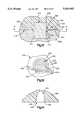
- FIG. 1is a sectional view of an implant having three cement compartments
- FIG. 2is a sectional view of the implant of FIG. 1 being applied to a bone having three matching cement compartments, and bone cement between;
- FIG. 3is a view similar to FIG. 2 after the implant is moved to a position against the bone to form cement cells filled with bone cement;
- FIG. 4is an enlarged view of one filled cement cell
- FIG. 5is an end view of an implant like the implant of FIG. 1 but having individual fill ports for three cement compartments;
- FIG. 6is an end view of a bone portion having three cement compartments
- FIG. 7is a view taken along line 7--7 of FIG. 5;
- FIG. 8illustrates filling of one of the cement compartments of the implant of FIGS. 5 and 7;
- FIG. 9is a view of an implant having one fill port and one exit channel for three cement compartments
- FIG. 10illustrates the filling of the cement compartments of the implant of FIG. 9;
- FIG. 11is a sectional view taken along line 11--11 of FIG. 3 and showing areas of discontinuity in the layer of bone cement;
- FIG. 12is a sectional view similar to FIG. 4 and showing an implant having a projecting ridge around its cement compartment to block lateral cement flow;
- FIG. 13is a view taken along line 13--13 of FIG. 12;
- FIG. 14is a view showing a rounded-bottom cement compartment in an implant.
- FIG. 1illustrates a patellar implant 10.
- the implant 10is made of a body of material 12.
- the material 12is preferably a biocompatible plastic material.
- a preferred materialis ultra high molecular weight polyethylene (UHMWPE).
- the implant 10can be a metal backed plastic component having a bone engagement portion made of metal and an articulating surface made of plastic.
- the implant 10has an arcuate articulating surface 20 and a planar bone engagement surface 22.
- the surfaces 20 and 22intersect at the outer periphery 24 of the implant 10.
- a bone engagement portion 26 of the implant 10includes the portion of the implant 10 adjacent to or close to the bone engagement surface 22.
- the bone engagement portion 26includes surfaces defining a plurality of cement compartments 30, 32, and 34 in the implant 10.
- Each of the cement compartments 30, 32, and 34is generally cylindrical in shape, and extends inwardly into the body of material 12 from the bone engagement surface 22.
- the cement compartment 30is defined by a cylindrical side wall 36 which extends between a planar end wall 38 and the plane of the bone engagement surface 22.
- the bone engagement surface 22is removed during formation of the cement compartment 30 at the location of the cement compartment 30, within the boundaries of the cylindrical side wall 36, so that cement (not shown in FIG. 1) can be placed into the cement compartment 30 in a direction from the bone engagement surface 22 toward the interior of the body of material 12 of the implant 10.
- the cement compartments 32 and 34are similar to the cement compartment 30.
- the cement compartment 32is defined by a cylindrical side wall 40 extending between a planar end wall 42 and the plane of the bone engagement surface 22.
- the cement compartment 34is defined by a cylindrical side wall 44 extending between a planar end wall 46 and the plane of the bone engagement surface 22.
- the patellar implant 10is designed to be implanted on a resected patella (kneecap) 50 shown fragmentarily in FIG. 2.
- the patella 50is resected to provide a planar implant engagement surface 52 for mating with the bone engagement surface 22 of the implant 10.
- a plurality of cement compartments 54, 56, and 58are formed in the patella 50.
- the cement compartments 54, 56, and 58are similar in size and shape to the cement compartments 30, 32, and 34 in the implant 10.
- the cement compartments 54, 56, and 58 in the patella 50are located in the patella 50 so as to be aligned with the respective cement compartments 30, 32, and 34 in the implant 10 when the implant 10 is placed adjacent the patella 50.
- a quantity of bone cement 60is placed between the implant and the patella.
- the implant 10 and the patella 50are then moved toward each other in the direction indicated by the arrows 62 and 64 (FIG. 2).
- the quantity of bone cement 60may be placed on the implant engagement surface 52 of the patella 50, with the implant 10 being then moved in the direction indicated by the arrow 62 into engagement with the bone cement.
- the bone cement 60may be placed on the bone engagement surface 22 of the implant 10, and the implant and bone cement then moved in the direction indicated by the arrow 62 into engagement with the bone 50.
- Theremay, of course, be movement of the patella 50 in the direction indicated by the arrow 64 to join the patella with the plant 10; such movement may be limited by the soft tissue attachment of the patella to the patients knee joint.
- Some cement 60may be placed on the implant 10 and the remainder of the cement placed on the patella 50, with the implant and patella then being pressed or squeezed toward each other.
- the bone engagement surface 22 of the implantis spaced from the implant engagement surface 52 of the bone, with the bone cement 60 disposed therebetween.
- a portion 70 of the bone cement 60is disposed in the cement compartment 30 in the implant 10.
- a portion 72 of the bone cement 60is disposed in the cement compartment 54 in the bone 50, which is aligned with the cement compartment 30.
- a portion 76 of the bone cement 60is disposed in the cement compartment 32 of the implant 10.
- a portion 78 of the bone cement 60is disposed in the cement compartment 56 of the bone 50, which is aligned with the cement compartment 32.
- a portion 80 of the bone cement 60is disposed in the cement compartment 34 in the implant 10.
- a portion 82 of the bone cement 60is disposed in the cement compartment 58, which is aligned with the cement compartment 34.
- a portion 84 of the bone cement 60is disposed between the bone engagement surface 22 and the bone 50 and extends outwardly from the aligned cement compartments 30 and 54.
- Another portion 86 of the bone cement 60extends between the aligned compartments 30 and 54 and the aligned cement compartments 32 and 56.
- a further portion 88 of the bone cement 60is disposed between the aligned cement compartments 32 and 56 and the aligned cement compartments 34 and 58.
- Another portion 90 of the bone cement 60extends outwardly from the aligned cement compartments 80 and 82 toward the outer edge 24 of the implant 10.
- the implant 10is pressed or squeezed firmly against the bone 50 as shown in FIG. 3 to remove as much bone cement as possible from between the bone engagement surface 22 of the implant and the implant engagement surface 52 of the bone.
- the amount of excess bone cement 60that is the bone cement which is not disposed within the various cement compartments when the implant 10 and the bone 50 are adjacent each other as in FIG. 3, depends on the amount of cement initially placed between the implant and the bone, and its location. Ideally, all the cement flows into the aligned cement compartments, but of course this may not be possible.
- the cement compartment 30 in the implantis aligned with the cement compartment 54 in the bone to form a cement cell 100.
- the cement cell 100extends between the implant 10 and the bone 50.
- Disposed within the cement cell 100is a plug or pin of cement 102 which includes the cement portion 70 in the cement compartment 30 of the implant 10 and the cement portion 70 in the cement compartment 54 of the bone 50.
- the cement cell 100extends between the implant 10 and the bone 50 across the interface 104 between the implant and the bone--that is, across the area of engagement between the implant and the bone.
- a very thin layer 106 of bone cement 60may be disposed between the bone engagement surface 22 of the implant 10 and the implant engagement surface 52 of the bone 50. This can be for several reasons. First, it may not be possible to provide matching planar surfaces on the implant 10 and on the bone 50 so as to allow complete contact of the two elements at all locations. Second, the implant 10 and bone 50 may be pressed toward each other unevenly, with more pressure at some locations and less at other locations. In any event, it is desirable that there not be a continuous layer of bone cement 60 between the implant 10 and the bone 50 for the entire extent of the interface between the implant and the bone. Thus, as seen in FIG. 11, areas of discontinuity of the bone cement are preferably present, to block propagation of any cracks throughout the entire interface. Any bone cement which squeezes out to the other edge 24 of the implant, as indicated at 108 and 110 in FIG. 3, is cleaned off.
- the cement plugsmake it possible to put the implant directly against the bone. This allows for minimizing the areas of continuity of bone cement between the implant and the bone. This minimizes the likelihood of propagation of a crack in the bone cement and minimizes the chance of failure of the cement system.
- the plugs or pins of cementprovide additional stability to secure the implant 10 to the bone 50.
- the maximum force, such as torquewhich can be transferred through the cement between the implant and the bone, is related to the adhesive interfacial shear stress between the cement and the implant.
- the strength of the implant/bone interfaceis governed by not only the adhesive shear stress but also the pure shear stress of the plugs or pins or cylinders of bone cement in the cement cells.
- the cement pinsmust fail in shear. This requires substantially more stress than that needed to cause failure of the slab.
- Bone cementmay be placed in the cement cells in a manner other than as described above.
- the implant 120(FIGS. 5, 7 and 8) has three cement compartments 122, 124, and 126 which are similar in size, shape and location to the cement compartments 30, 32 and 34 of the implant 10 (FIGS. 1-4). However, the cement compartments in the implant 120 are fillable through fill ports extending between the respective cement compartments and the radially outer edge 128 of the implant 120.
- a first fill port 130(FIG. 5) is defined by a partial cylindrical surface 132 extending radially outwardly from the cement compartment 122 to the implant periphery 128.
- a second fill port 134extends radially between the cement compartment 124 and the periphery 128 and is partially defined by a partial cylindrical surface 136.
- a third fill port 138partially defined by a partial cylindrical surface 140, extends radially between the cement compartment 126 and the implant periphery 128.
- the cement compartments 122, 124, and 126, with their respective fill ports 130, 134, and 138,are disposed in a bone engagement portion 142 of the implant 120.
- the bone engagement portion 142is the lower portion (as viewed in FIG. 7) of the implant 120.
- the implant 120also has an arcuate articulating surface 144 and a generally planar bone engagement surface 146.
- the implant 120has a circular shape in plan.
- the cement compartments 122, 124, and 126are spaced equally about a central axis 150 of the implant 120.
- the cement compartments 122, 124, and 126are designed to mate with matching cement compartments 154, 156, and 158 in a bone 160 (FIG. 6) having an implant engagement surface 162.
- the implant 120(FIG. 5) has two alignment markers 170 and 172.
- the alignment marker 170is a notch 174 cut into the periphery 128 of the implant 120 and defined by two side lines 176 and 178.
- the alignment marker 172is a notch 180 cut into the periphery 128 of the implant 120 and defined by two side lines 182 and 184.
- a template(not shown) is used to place alignment markers 186 and 188 (FIG. 6) on the bone 160, preferably at the same time as the cement compartments 154, 156, and 158 are made.
- the alignment marker 186is a notch 190 defined by two side lines 192 and 194 scribed into the implant engagement surface 162 of the bone 160.
- the alignment marker 188is a V-shaped notch 196 defined by two side lines 198 and 200 scribed into the implant engagement surface 162 of the bone 60.
- the implant 120 in FIG. 5is aligned with or placed on the bone 160 in FIG. 6 by rotating or mirroring the implant 120 about an imaginary line extending vertically on the sheet of drawings between FIGS. 5 and 6.
- the alignment marker 172is placed on and in alignment with the alignment marker 186.
- the alignment marker 170 of the implant 120is placed on and in alignment with the alignment marker 188 on the bone 160.
- the cements compartment 124 of the implant 120is aligned with the cement compartment 154 on the bone 160.
- the cement compartments 122 and 126 of the implant 120are aligned with, respectively, cement compartments 158 and 156 of the bone 160.
- the cement compartment 122 in the implant 120aligns with the cement compartment 154 in bone 160 to form a cement cell 164.
- the cement compartment 126 in the implant 120aligns with the cement compartment 156 in the bone 160 to form a second cement cell 166.
- the cement compartment 124 in the implant 120aligns with the cement compartment 158 in the bone 160 to form a third cement cell 168.
- the cement cells 164, 166, and 168are filled with bone cement in a manner as described below to secure the implant to the bone.
- the cement cell 164is filled through the fill port 130.
- the cement cell 166is filled through the fill port 138 (FIG. 5) for the cement compartment 126.
- the cement cell 168is filled through the fill port 134.
- a deviceis used to introduce cement into the cement cells of the aligned implant 120 and bone 160.
- the devicemay be a syringe 210 having a needle 212 which is inserted into the fill port 134, for example.
- Bone cement(not shown) is injected through the syringe 210 and the needle 212 to fill the cement cell 168. Excess bone cement will be present in the fill port 134.
- the cement cell 164is filled through the fill port 130, and the cement cell 166 is filled through the fill port 138 (FIG. 5).
- FIGS. 9 and 10illustrate another embodiment of the invention in which an implant 230 has three cement compartments 232, 234, and 236 which are all filled via one fill port 238.
- the fill port 238includes a straight portion 240 extending from the outer periphery 242 of the implant 230 to a first arcuate fill port portion 242.
- the first arcuate fill port portion 232extends between and interconnects the cement compartments 234 and 236.
- a second arcuate fill port portion 244extends between and interconnects the cement compartment 236 and the cement compartment 232.
- a third arcuate fill port portion 246extends between and interconnects the cement compartment 234 and the cement compartment 232.
- An exit channel 250extends from the portion 244 of the fill port 238 to the outer periphery 242 of the implant 230, at a location diametrically opposite from the fill port portion 240.
- the implant 230has a bone engagement portion 252, a bone engagement surface 254 and an articulating surface 256
- FIG. 10illustrates the securing of the implant 230 to a bone 260.
- the bone 260has an implant engagement surface 262 which is placed in mating engagement with the bone engagement surface 254 of the implant 230.
- the implant 230is aligned with the bone 260 so that the cement compartment 232 aligns with a cement compartment 264 in the bone 260 to form a cement cell 266 extending between the implant 230 and the bone 260.
- the cement compartment 236 in the implant 230aligns with a cement compartment 268 in the bone 260 to form a cement cell 270 extending between the implant and the bone.
- the cement compartment 234 in the implant 230aligns with a cement compartment 272 in the bone 260 to form a cement cell 274 extending between the implant and the bone.
- the cement cells 266, 270 and 274are filled by insertion of bone cement 275 through a device such as a syringe 276 (FIG. 10) having a needle 278.
- the needle 278is placed in the fill port portion 240 and bone cement 275 is injected into the fill port portion 240.
- bone cement 275continuous to be injected, it flows through the remaining portions 242, 244 and 246 of the fill port 238.
- the cement cells 266, 270 and 274fill with bone cement 275. Excess cement 275 flows outwardly from the fill port 238 through the exit channel 250 and may be cleaned off the outer surface 256 of the implant 230.
- FIG. 11illustrates how the present invention can minimize the possibility of there being a continuous layer of bone cement across the entire extent of the interface between an implant and a bone.
- the cement cell 100(FIGS. 3 and 11) is filled with a plug or pin of bone cement 102.
- the cement compartments 34 and 58(FIG. 3) form a cement cell 280 (FIGS. 3 and 11) filled with a plug of cement 282.
- the cement compartments 32 and 56 (FIG. 3)form a cement cell 284 (FIGS. 3 and 11) filled with a plug of bone cement 286.
- the plugs of bone cement 102, 282, and 286are discrete and separate from each other.
- An implant in accordance with the present inventionmay include ridge portions around cement compartments in the implant to block flow of cement out of the cement compartment between the implant and the bone.
- One such ridge portionis illustrated schematically in FIGS. 12 and 13.
- An implant 300is disposed in mating engagement with a bone portion 302.
- the implant 300has a bone engagement surface 304 disposed adjacent an implant engagement surface 306 of the bone portion 302.
- a cement compartment 308 in the implant 300is aligned with a cement compartment 310 in the bone portion 302.
- the aligned cement compartments 308 and 310together define a cement cell 312 having a quantity of bone cement 314 therein.
- the plug of bone cement 314extends between the implant 300 and the bone portion 302.
- the plug of bone cement 314extends into the implant 300 for a substantial distance in a direction away from the interface or area of engagement 316 between the implant 300 and the bone portion 302.
- the plug of cement 314also extends into the bone portion 302 in a direction away from the interface 316, the bone engagement surface 304 and the implant engagement surface 306.
- the implant 300has a ridge portion 320 extending around the cement compartment 308.
- the ridge portion 320has an outer cylindrical surface 322 extending outwardly from the implant bone engagement surface 304; an annular end face 324 extending radially inwardly from the surface 322; and an inner cylindrical surface 326 extending parallel to the outer cylindrical surface 322 from the annular end face 324 to the plane of the bone engagement surface 304.
- the implant ridge portion 320extends into the bone portion 302, below the implant engagement surface 306, as illustrated in FIG. 12, when the implant 300 is positioned adjacent the bone portion 302.
- the ridge portion 320blocks the flow of cement out of the cement cell 312 into the areas 328 and 330 adjacent the cement cell and between the implant 300 and the bone 302.
- the ridge portion 320is pressed into the bone portion 302, below the implant engagement surface 306, when the implant 300 is positioned adjacent the bone 302. Ridge portions may also be provided on fill ports.
- FIG. 14illustrates a cement compartment 340 in an implant 342.
- the cement compartment 340has a rounded bottom portion 344 to reduce stress concentrations in the plug of bone cement and/or in the implant itself.
- the cement compartment 340has a tapered side wall 346 and an arcuate entrance edge 348.
- the round cross-sectional shape of the illustrated cement compartmentsis a result of the drilling process used to form them. Other shapes could be used as suitable and feasible.
- one embodiment of the inventionis in a patellar implant.
- Typical outer diameters of patellar implantswould be 32 mm, 35 mm, and 38 mm to fit different size patients.
- the height of the implantwould be between 6 mm and 8 mm.
- Compartment diameters currently being consideredare under 10 mm, with a preferred range being between 6 mm and 8 mm.
- the compartmentshave a height of 1, 2, or 3 mm in each of the implant and the bone.
- the cement cellshave a height of 2 mm, 4 mm, or 6 mm.
- the fill portsare preferably 3 mm to 5 mm in diameter with a height of 2 mm to 3 mm.
- the angular placement of the compartments and of the fill portsdepend on the number of each.
- the fill portscould be spaced equally along an imaginary circle as illustrated in the drawings. Alternatively, there could be a large number of smaller compartments spread over the surface, as on the surface of a golf ball.
- the presently preferred implant designincludes 3 cement compartments with a height of 2 mm and a diameter of 7-8 mm, providing cement cells with a height of 4 mm. Fill ports are not used.
- the implantis solid UHMWPE with a maximum thickness of 6-8 mm and an outer diameter of 32, 35, or 38 mm depending on the bone size. Alignment is made by two small notches 90° apart on the implant and on the bone.
Landscapes
- Health & Medical Sciences (AREA)
- Orthopedic Medicine & Surgery (AREA)
- Life Sciences & Earth Sciences (AREA)
- Animal Behavior & Ethology (AREA)
- Surgery (AREA)
- Veterinary Medicine (AREA)
- Public Health (AREA)
- Engineering & Computer Science (AREA)
- Biomedical Technology (AREA)
- Heart & Thoracic Surgery (AREA)
- General Health & Medical Sciences (AREA)
- Transplantation (AREA)
- Vascular Medicine (AREA)
- Oral & Maxillofacial Surgery (AREA)
- Cardiology (AREA)
- Nuclear Medicine, Radiotherapy & Molecular Imaging (AREA)
- Physical Education & Sports Medicine (AREA)
- Medical Informatics (AREA)
- Molecular Biology (AREA)
- Prostheses (AREA)
Abstract
Description
Claims (74)
Priority Applications (3)
| Application Number | Priority Date | Filing Date | Title |
|---|---|---|---|
| US08/377,759US5624462A (en) | 1993-04-12 | 1995-01-24 | Bone implant and method of securing |
| US08/735,916US6217617B1 (en) | 1993-04-12 | 1996-10-24 | Bone implant and method of securing |
| US09/815,405US20010023371A1 (en) | 1993-04-12 | 2001-03-22 | Bone implant and method of securing |
Applications Claiming Priority (2)
| Application Number | Priority Date | Filing Date | Title |
|---|---|---|---|
| US08/046,220US5441538A (en) | 1993-04-12 | 1993-04-12 | Bone implant and method of securing |
| US08/377,759US5624462A (en) | 1993-04-12 | 1995-01-24 | Bone implant and method of securing |
Related Parent Applications (1)
| Application Number | Title | Priority Date | Filing Date |
|---|---|---|---|
| US08/046,220DivisionUS5441538A (en) | 1993-04-12 | 1993-04-12 | Bone implant and method of securing |
Related Child Applications (1)
| Application Number | Title | Priority Date | Filing Date |
|---|---|---|---|
| US08/735,916DivisionUS6217617B1 (en) | 1993-04-12 | 1996-10-24 | Bone implant and method of securing |
Publications (1)
| Publication Number | Publication Date |
|---|---|
| US5624462Atrue US5624462A (en) | 1997-04-29 |
Family
ID=21942246
Family Applications (4)
| Application Number | Title | Priority Date | Filing Date |
|---|---|---|---|
| US08/046,220Expired - LifetimeUS5441538A (en) | 1993-04-12 | 1993-04-12 | Bone implant and method of securing |
| US08/377,759Expired - LifetimeUS5624462A (en) | 1993-04-12 | 1995-01-24 | Bone implant and method of securing |
| US08/735,916Expired - LifetimeUS6217617B1 (en) | 1993-04-12 | 1996-10-24 | Bone implant and method of securing |
| US09/815,405AbandonedUS20010023371A1 (en) | 1993-04-12 | 2001-03-22 | Bone implant and method of securing |
Family Applications Before (1)
| Application Number | Title | Priority Date | Filing Date |
|---|---|---|---|
| US08/046,220Expired - LifetimeUS5441538A (en) | 1993-04-12 | 1993-04-12 | Bone implant and method of securing |
Family Applications After (2)
| Application Number | Title | Priority Date | Filing Date |
|---|---|---|---|
| US08/735,916Expired - LifetimeUS6217617B1 (en) | 1993-04-12 | 1996-10-24 | Bone implant and method of securing |
| US09/815,405AbandonedUS20010023371A1 (en) | 1993-04-12 | 2001-03-22 | Bone implant and method of securing |
Country Status (1)
| Country | Link |
|---|---|
| US (4) | US5441538A (en) |
Cited By (32)
| Publication number | Priority date | Publication date | Assignee | Title |
|---|---|---|---|---|
| US6610079B1 (en) | 1999-12-14 | 2003-08-26 | Linvatec Corporation | Fixation system and method |
| US20040068267A1 (en)* | 2000-06-27 | 2004-04-08 | Fraser Harvie | Surgical procedures and instruments |
| US20050049707A1 (en)* | 2003-08-29 | 2005-03-03 | Ferree Bret A. | Cemented artificial disc replacements |
| US20080306602A1 (en)* | 2007-06-07 | 2008-12-11 | Worland Richard L | Tibia Cement Impaction System |
| US20100331846A1 (en)* | 2009-04-02 | 2010-12-30 | Martin Malawar | Bone rifling system and method of preparing a bone using such system |
| US8747439B2 (en) | 2000-03-13 | 2014-06-10 | P Tech, Llc | Method of using ultrasonic vibration to secure body tissue with fastening element |
| US8808329B2 (en) | 1998-02-06 | 2014-08-19 | Bonutti Skeletal Innovations Llc | Apparatus and method for securing a portion of a body |
| US8814902B2 (en) | 2000-05-03 | 2014-08-26 | Bonutti Skeletal Innovations Llc | Method of securing body tissue |
| US8845699B2 (en) | 1999-08-09 | 2014-09-30 | Bonutti Skeletal Innovations Llc | Method of securing tissue |
| US8845687B2 (en) | 1996-08-19 | 2014-09-30 | Bonutti Skeletal Innovations Llc | Anchor for securing a suture |
| US9237957B2 (en) | 2011-09-16 | 2016-01-19 | Globus Medical, Inc. | Low profile plate |
| US9358127B2 (en) | 2008-09-02 | 2016-06-07 | Globus Medical, Inc. | Intervertebral fusion implant |
| US9402738B2 (en) | 2013-02-14 | 2016-08-02 | Globus Medical, Inc. | Devices and methods for correcting vertebral misalignment |
| US9539109B2 (en) | 2011-09-16 | 2017-01-10 | Globus Medical, Inc. | Low profile plate |
| US9585765B2 (en) | 2013-02-14 | 2017-03-07 | Globus Medical, Inc | Devices and methods for correcting vertebral misalignment |
| US9615936B2 (en) | 2009-06-04 | 2017-04-11 | Globus Medical, Inc. | Intervertebral fusion implant |
| US9681959B2 (en) | 2011-09-16 | 2017-06-20 | Globus Medical, Inc. | Low profile plate |
| US9744049B2 (en) | 2007-11-16 | 2017-08-29 | DePuy Synthes Products, Inc. | Low profile intervertebral implant |
| US9770238B2 (en) | 2001-12-03 | 2017-09-26 | P Tech, Llc | Magnetic positioning apparatus |
| US9848992B2 (en) | 2010-12-21 | 2017-12-26 | DePuy Synthes Products, Inc. | Intervertebral implants, systems, and methods of use |
| US9848994B2 (en) | 2011-09-16 | 2017-12-26 | Globus Medical, Inc. | Low profile plate |
| US9867718B2 (en) | 2014-10-22 | 2018-01-16 | DePuy Synthes Products, Inc. | Intervertebral implants, systems, and methods of use |
| US9895237B2 (en) | 2010-04-08 | 2018-02-20 | Globus Medical, Inc. | Intervertebral implant |
| US10064740B2 (en) | 2003-02-06 | 2018-09-04 | DePuy Synthes Products, LLC | Intervertebral implant |
| US10245155B2 (en) | 2011-09-16 | 2019-04-02 | Globus Medical, Inc. | Low profile plate |
| US10433976B2 (en) | 2008-11-07 | 2019-10-08 | DePuy Synthes Products, Inc. | Zero-profile interbody spacer and coupled plate assembly |
| US10492922B2 (en) | 2002-02-19 | 2019-12-03 | DePuy Synthes Products, Inc. | Intervertebral implant |
| US10512548B2 (en) | 2006-02-27 | 2019-12-24 | DePuy Synthes Products, Inc. | Intervertebral implant with fixation geometry |
| US10893948B2 (en) | 2017-11-02 | 2021-01-19 | Howmedica Osteonics Corp. | Rotary arc patella articulating geometry |
| US11717417B2 (en) | 2011-09-16 | 2023-08-08 | Globus Medical Inc. | Low profile plate |
| US11730528B2 (en) | 2012-05-30 | 2023-08-22 | Globus Medical, Inc. | Aligning vertebral bodies |
| US11890320B2 (en) | 2015-04-20 | 2024-02-06 | The Board Of Regents Of The University Of Texas System | CLEC11A is a bone growth agent |
Families Citing this family (89)
| Publication number | Priority date | Publication date | Assignee | Title |
|---|---|---|---|---|
| US20030229372A1 (en)* | 1994-01-26 | 2003-12-11 | Kyphon Inc. | Inflatable device for use in surgical protocols relating to treatment of fractured or diseased bone |
| US20060100635A1 (en)* | 1994-01-26 | 2006-05-11 | Kyphon, Inc. | Inflatable device for use in surgical protocol relating to fixation of bone |
| ATE361028T1 (en) | 1994-01-26 | 2007-05-15 | Kyphon Inc | IMPROVED INFLATABLE DEVICE FOR USE IN SURGICAL METHODS OF FIXATION OF BONE |
| WO1995020362A1 (en)* | 1994-01-26 | 1995-08-03 | Reiley Mark A | Improved inflatable device for use in surgical protocol relating to fixation of bone |
| US6248110B1 (en)* | 1994-01-26 | 2001-06-19 | Kyphon, Inc. | Systems and methods for treating fractured or diseased bone using expandable bodies |
| US20050131269A1 (en)* | 1995-06-07 | 2005-06-16 | Talmadge Karen D. | System and method for delivering a therapeutic agent for bone disease |
| US20050131267A1 (en)* | 1995-06-07 | 2005-06-16 | Talmadge Karen D. | System and method for delivering a therapeutic agent for bone disease |
| JP3495161B2 (en) | 1995-11-30 | 2004-02-09 | 京セラ株式会社 | Femoral component of a knee prosthesis |
| EP0845965A1 (en)* | 1996-06-18 | 1998-06-10 | Mehran Kasra | Bone prosthesis fixation device and methods of using same |
| US7635390B1 (en) | 2000-01-14 | 2009-12-22 | Marctec, Llc | Joint replacement component having a modular articulating surface |
| US7094251B2 (en) | 2002-08-27 | 2006-08-22 | Marctec, Llc. | Apparatus and method for securing a suture |
| US9138222B2 (en) | 2000-03-13 | 2015-09-22 | P Tech, Llc | Method and device for securing body tissue |
| US8932330B2 (en) | 2000-03-13 | 2015-01-13 | P Tech, Llc | Method and device for securing body tissue |
| AU5326701A (en)* | 2000-04-05 | 2001-10-23 | Kyphon Inc | Methods and devices for treating fractured and/or diseased bone |
| US6632235B2 (en) | 2001-04-19 | 2003-10-14 | Synthes (U.S.A.) | Inflatable device and method for reducing fractures in bone and in treating the spine |
| US6855150B1 (en)* | 2001-07-13 | 2005-02-15 | Timothy R. Linehan | Patellar trial and drill guide for use in knee replacement surgery |
| US7708741B1 (en) | 2001-08-28 | 2010-05-04 | Marctec, Llc | Method of preparing bones for knee replacement surgery |
| US9155544B2 (en) | 2002-03-20 | 2015-10-13 | P Tech, Llc | Robotic systems and methods |
| US20040002759A1 (en)* | 2002-06-28 | 2004-01-01 | Ferree Bret A. | Fusion and arthroplasty devices configured to receive bone growth promoting substances |
| WO2004047689A1 (en)* | 2002-11-21 | 2004-06-10 | Sdgi Holdings, Inc. | Systems and techniques for intravertebral spinal stablization with expandable devices |
| AU2004212942A1 (en) | 2003-02-14 | 2004-09-02 | Depuy Spine, Inc. | In-situ formed intervertebral fusion device |
| US7497864B2 (en) | 2003-04-30 | 2009-03-03 | Marctec, Llc. | Tissue fastener and methods for using same |
| US20080039873A1 (en) | 2004-03-09 | 2008-02-14 | Marctec, Llc. | Method and device for securing body tissue |
| US9173647B2 (en) | 2004-10-26 | 2015-11-03 | P Tech, Llc | Tissue fixation system |
| US9271766B2 (en) | 2004-10-26 | 2016-03-01 | P Tech, Llc | Devices and methods for stabilizing tissue and implants |
| US20060089646A1 (en) | 2004-10-26 | 2006-04-27 | Bonutti Peter M | Devices and methods for stabilizing tissue and implants |
| US9463012B2 (en) | 2004-10-26 | 2016-10-11 | P Tech, Llc | Apparatus for guiding and positioning an implant |
| US9089323B2 (en) | 2005-02-22 | 2015-07-28 | P Tech, Llc | Device and method for securing body tissue |
| US7572293B2 (en)* | 2005-06-30 | 2009-08-11 | Depuy Products, Inc. | Tibial insert and associated surgical method |
| WO2008103781A2 (en) | 2007-02-21 | 2008-08-28 | Benvenue Medical, Inc. | Devices for treating the spine |
| AU2006279558B2 (en) | 2005-08-16 | 2012-05-17 | Izi Medical Products, Llc | Spinal tissue distraction devices |
| US8366773B2 (en) | 2005-08-16 | 2013-02-05 | Benvenue Medical, Inc. | Apparatus and method for treating bone |
| US11253296B2 (en) | 2006-02-07 | 2022-02-22 | P Tech, Llc | Methods and devices for intracorporeal bonding of implants with thermal energy |
| US7967820B2 (en) | 2006-02-07 | 2011-06-28 | P Tech, Llc. | Methods and devices for trauma welding |
| US8496657B2 (en) | 2006-02-07 | 2013-07-30 | P Tech, Llc. | Methods for utilizing vibratory energy to weld, stake and/or remove implants |
| US11278331B2 (en) | 2006-02-07 | 2022-03-22 | P Tech Llc | Method and devices for intracorporeal bonding of implants with thermal energy |
| US9439642B2 (en) | 2006-02-07 | 2016-09-13 | P Tech, Llc | Methods and devices for utilizing bondable materials |
| US11246638B2 (en) | 2006-05-03 | 2022-02-15 | P Tech, Llc | Methods and devices for utilizing bondable materials |
| US8540778B2 (en)* | 2006-06-22 | 2013-09-24 | DePuy Synthes Products, LLC | Tibial insert having multiple keels |
| US8764839B2 (en)* | 2006-06-22 | 2014-07-01 | DePuy Synthes Products, LLC | Tibial insert having a keel including a bore formed therein |
| US8114165B2 (en)* | 2006-06-22 | 2012-02-14 | Depuy Products, Inc. | Tibial insert and method for implanting the same |
| US8163027B2 (en)* | 2006-06-22 | 2012-04-24 | Depuy Products, Inc. | Tibial insert having a reinforced keel |
| WO2008070863A2 (en) | 2006-12-07 | 2008-06-12 | Interventional Spine, Inc. | Intervertebral implant |
| US8617185B2 (en) | 2007-02-13 | 2013-12-31 | P Tech, Llc. | Fixation device |
| EP2124778B1 (en) | 2007-02-21 | 2019-09-25 | Benvenue Medical, Inc. | Devices for treating the spine |
| WO2008116203A2 (en) | 2007-03-22 | 2008-09-25 | Marctec, Llc | Methods and devices for intracorporeal bonding or interlocking of implants with thermal energy |
| US8900307B2 (en) | 2007-06-26 | 2014-12-02 | DePuy Synthes Products, LLC | Highly lordosed fusion cage |
| US20100198354A1 (en)* | 2007-08-01 | 2010-08-05 | Jeffrey Halbrecht | Method and system for patella tendon realignment |
| CA2698057A1 (en) | 2007-08-30 | 2009-03-05 | P Tech, Llc | Methods and devices for utilizing thermal energy to bond, stake and/or remove implants |
| EP2237748B1 (en) | 2008-01-17 | 2012-09-05 | Synthes GmbH | An expandable intervertebral implant |
| US8936641B2 (en) | 2008-04-05 | 2015-01-20 | DePuy Synthes Products, LLC | Expandable intervertebral implant |
| WO2010099123A2 (en) | 2009-02-24 | 2010-09-02 | Mako Surgical Corp. | Prosthetic device, method of planning bone removal for implantation of prosthetic device, and robotic system |
| US8535327B2 (en) | 2009-03-17 | 2013-09-17 | Benvenue Medical, Inc. | Delivery apparatus for use with implantable medical devices |
| US8945222B2 (en)* | 2009-03-20 | 2015-02-03 | Linares Medical Devices, Llc | Wear compensating joint assembly incorporating a pressurized fluid injectable reservoir upwardly biasing a hardened plastic with a wear surface |
| US9526620B2 (en) | 2009-03-30 | 2016-12-27 | DePuy Synthes Products, Inc. | Zero profile spinal fusion cage |
| US9278004B2 (en) | 2009-08-27 | 2016-03-08 | Cotera, Inc. | Method and apparatus for altering biomechanics of the articular joints |
| US10349980B2 (en) | 2009-08-27 | 2019-07-16 | The Foundry, Llc | Method and apparatus for altering biomechanics of the shoulder |
| CA2771332C (en) | 2009-08-27 | 2020-11-10 | Cotera, Inc. | Method and apparatus for force redistribution in articular joints |
| US9861408B2 (en) | 2009-08-27 | 2018-01-09 | The Foundry, Llc | Method and apparatus for treating canine cruciate ligament disease |
| US9668868B2 (en) | 2009-08-27 | 2017-06-06 | Cotera, Inc. | Apparatus and methods for treatment of patellofemoral conditions |
| US9393129B2 (en) | 2009-12-10 | 2016-07-19 | DePuy Synthes Products, Inc. | Bellows-like expandable interbody fusion cage |
| US9907560B2 (en) | 2010-06-24 | 2018-03-06 | DePuy Synthes Products, Inc. | Flexible vertebral body shavers |
| US8979860B2 (en) | 2010-06-24 | 2015-03-17 | DePuy Synthes Products. LLC | Enhanced cage insertion device |
| US8623091B2 (en) | 2010-06-29 | 2014-01-07 | DePuy Synthes Products, LLC | Distractible intervertebral implant |
| US8727203B2 (en) | 2010-09-16 | 2014-05-20 | Howmedica Osteonics Corp. | Methods for manufacturing porous orthopaedic implants |
| US9402732B2 (en) | 2010-10-11 | 2016-08-02 | DePuy Synthes Products, Inc. | Expandable interspinous process spacer implant |
| US8814873B2 (en) | 2011-06-24 | 2014-08-26 | Benvenue Medical, Inc. | Devices and methods for treating bone tissue |
| US9351834B2 (en) | 2011-09-12 | 2016-05-31 | Biomet Manufacturing, Llc | Negative-positive pressurizable implant |
| US9468466B1 (en) | 2012-08-24 | 2016-10-18 | Cotera, Inc. | Method and apparatus for altering biomechanics of the spine |
| US10076377B2 (en) | 2013-01-05 | 2018-09-18 | P Tech, Llc | Fixation systems and methods |
| US9717601B2 (en) | 2013-02-28 | 2017-08-01 | DePuy Synthes Products, Inc. | Expandable intervertebral implant, system, kit and method |
| US9522070B2 (en) | 2013-03-07 | 2016-12-20 | Interventional Spine, Inc. | Intervertebral implant |
| US9427334B2 (en)* | 2013-03-08 | 2016-08-30 | Stryker Corporation | Bone pads |
| US10085783B2 (en) | 2013-03-14 | 2018-10-02 | Izi Medical Products, Llc | Devices and methods for treating bone tissue |
| US11426290B2 (en) | 2015-03-06 | 2022-08-30 | DePuy Synthes Products, Inc. | Expandable intervertebral implant, system, kit and method |
| US10058393B2 (en) | 2015-10-21 | 2018-08-28 | P Tech, Llc | Systems and methods for navigation and visualization |
| EP3474784A2 (en) | 2016-06-28 | 2019-05-01 | Eit Emerging Implant Technologies GmbH | Expandable and angularly adjustable intervertebral cages with articulating joint |
| US11510788B2 (en) | 2016-06-28 | 2022-11-29 | Eit Emerging Implant Technologies Gmbh | Expandable, angularly adjustable intervertebral cages |
| US10888433B2 (en) | 2016-12-14 | 2021-01-12 | DePuy Synthes Products, Inc. | Intervertebral implant inserter and related methods |
| US10398563B2 (en) | 2017-05-08 | 2019-09-03 | Medos International Sarl | Expandable cage |
| US11344424B2 (en) | 2017-06-14 | 2022-05-31 | Medos International Sarl | Expandable intervertebral implant and related methods |
| US10940016B2 (en) | 2017-07-05 | 2021-03-09 | Medos International Sarl | Expandable intervertebral fusion cage |
| US11446156B2 (en) | 2018-10-25 | 2022-09-20 | Medos International Sarl | Expandable intervertebral implant, inserter instrument, and related methods |
| US11896476B2 (en) | 2020-01-02 | 2024-02-13 | Zkr Orthopedics, Inc. | Patella tendon realignment implant with changeable shape |
| US11426286B2 (en) | 2020-03-06 | 2022-08-30 | Eit Emerging Implant Technologies Gmbh | Expandable intervertebral implant |
| WO2021231253A1 (en) | 2020-05-11 | 2021-11-18 | Zkr Orthopedics, Inc. | Adjustable patellar tendon realignment implant |
| US11850160B2 (en) | 2021-03-26 | 2023-12-26 | Medos International Sarl | Expandable lordotic intervertebral fusion cage |
| US11752009B2 (en) | 2021-04-06 | 2023-09-12 | Medos International Sarl | Expandable intervertebral fusion cage |
| US12090064B2 (en) | 2022-03-01 | 2024-09-17 | Medos International Sarl | Stabilization members for expandable intervertebral implants, and related systems and methods |
Citations (8)
| Publication number | Priority date | Publication date | Assignee | Title |
|---|---|---|---|---|
| US3698017A (en)* | 1969-08-11 | 1972-10-17 | Nat Res Dev | Prosthetic acetabular devices |
| US3774244A (en)* | 1972-02-08 | 1973-11-27 | Relief Ruptured And Crippled S | Knee-joint prosthesis |
| US3869731A (en)* | 1973-02-14 | 1975-03-11 | Univ California | Articulated two-part prosthesis replacing the knee joint |
| US4055862A (en)* | 1976-01-23 | 1977-11-01 | Zimmer Usa, Inc. | Human body implant of graphitic carbon fiber reinforced ultra-high molecular weight polyethylene |
| US4081866A (en)* | 1977-02-02 | 1978-04-04 | Howmedica, Inc. | Total anatomical knee prosthesis |
| US4711233A (en)* | 1985-06-26 | 1987-12-08 | Brown Byron L | Method and apparatus for cementing an acetabular cup to an acetabulum |
| US5171276A (en)* | 1990-01-08 | 1992-12-15 | Caspari Richard B | Knee joint prosthesis |
| US5201768A (en)* | 1990-01-08 | 1993-04-13 | Caspari Richard B | Prosthesis for implant on the tibial plateau of the knee |
Family Cites Families (3)
| Publication number | Priority date | Publication date | Assignee | Title |
|---|---|---|---|---|
| US4608052A (en)* | 1984-04-25 | 1986-08-26 | Minnesota Mining And Manufacturing Company | Implant with attachment surface |
| US4979957A (en)* | 1989-09-11 | 1990-12-25 | Zimmer, Inc. | Textured prosthetic implant |
| US5197986A (en)* | 1990-04-11 | 1993-03-30 | Mikhail Michael W E | Recessed patellar prosthesis |
- 1993
- 1993-04-12USUS08/046,220patent/US5441538A/ennot_activeExpired - Lifetime
- 1995
- 1995-01-24USUS08/377,759patent/US5624462A/ennot_activeExpired - Lifetime
- 1996
- 1996-10-24USUS08/735,916patent/US6217617B1/ennot_activeExpired - Lifetime
- 2001
- 2001-03-22USUS09/815,405patent/US20010023371A1/ennot_activeAbandoned
Patent Citations (8)
| Publication number | Priority date | Publication date | Assignee | Title |
|---|---|---|---|---|
| US3698017A (en)* | 1969-08-11 | 1972-10-17 | Nat Res Dev | Prosthetic acetabular devices |
| US3774244A (en)* | 1972-02-08 | 1973-11-27 | Relief Ruptured And Crippled S | Knee-joint prosthesis |
| US3869731A (en)* | 1973-02-14 | 1975-03-11 | Univ California | Articulated two-part prosthesis replacing the knee joint |
| US4055862A (en)* | 1976-01-23 | 1977-11-01 | Zimmer Usa, Inc. | Human body implant of graphitic carbon fiber reinforced ultra-high molecular weight polyethylene |
| US4081866A (en)* | 1977-02-02 | 1978-04-04 | Howmedica, Inc. | Total anatomical knee prosthesis |
| US4711233A (en)* | 1985-06-26 | 1987-12-08 | Brown Byron L | Method and apparatus for cementing an acetabular cup to an acetabulum |
| US5171276A (en)* | 1990-01-08 | 1992-12-15 | Caspari Richard B | Knee joint prosthesis |
| US5201768A (en)* | 1990-01-08 | 1993-04-13 | Caspari Richard B | Prosthesis for implant on the tibial plateau of the knee |
Cited By (59)
| Publication number | Priority date | Publication date | Assignee | Title |
|---|---|---|---|---|
| US8845687B2 (en) | 1996-08-19 | 2014-09-30 | Bonutti Skeletal Innovations Llc | Anchor for securing a suture |
| US8808329B2 (en) | 1998-02-06 | 2014-08-19 | Bonutti Skeletal Innovations Llc | Apparatus and method for securing a portion of a body |
| US8845699B2 (en) | 1999-08-09 | 2014-09-30 | Bonutti Skeletal Innovations Llc | Method of securing tissue |
| US6610079B1 (en) | 1999-12-14 | 2003-08-26 | Linvatec Corporation | Fixation system and method |
| US8747439B2 (en) | 2000-03-13 | 2014-06-10 | P Tech, Llc | Method of using ultrasonic vibration to secure body tissue with fastening element |
| US8814902B2 (en) | 2000-05-03 | 2014-08-26 | Bonutti Skeletal Innovations Llc | Method of securing body tissue |
| US7144414B2 (en) | 2000-06-27 | 2006-12-05 | Smith & Nephew, Inc. | Surgical procedures and instruments |
| US20040068267A1 (en)* | 2000-06-27 | 2004-04-08 | Fraser Harvie | Surgical procedures and instruments |
| US9770238B2 (en) | 2001-12-03 | 2017-09-26 | P Tech, Llc | Magnetic positioning apparatus |
| US10492922B2 (en) | 2002-02-19 | 2019-12-03 | DePuy Synthes Products, Inc. | Intervertebral implant |
| US10660765B2 (en) | 2003-02-06 | 2020-05-26 | DePuy Synthes Products, Inc. | Intervertebral implant |
| US10064740B2 (en) | 2003-02-06 | 2018-09-04 | DePuy Synthes Products, LLC | Intervertebral implant |
| US20050049707A1 (en)* | 2003-08-29 | 2005-03-03 | Ferree Bret A. | Cemented artificial disc replacements |
| US11696837B2 (en) | 2006-02-27 | 2023-07-11 | DePuy Synthes Products, Inc. | Intervertebral implant with fixation geometry |
| US10512548B2 (en) | 2006-02-27 | 2019-12-24 | DePuy Synthes Products, Inc. | Intervertebral implant with fixation geometry |
| US20080306602A1 (en)* | 2007-06-07 | 2008-12-11 | Worland Richard L | Tibia Cement Impaction System |
| US10137003B2 (en) | 2007-11-16 | 2018-11-27 | DePuy Synthes Products, Inc. | Low profile intervertebral implant |
| US10543102B2 (en) | 2007-11-16 | 2020-01-28 | DePuy Synthes Products, Inc. | Low profile intervertebral implant |
| US9744049B2 (en) | 2007-11-16 | 2017-08-29 | DePuy Synthes Products, Inc. | Low profile intervertebral implant |
| US9364343B2 (en) | 2008-09-02 | 2016-06-14 | Globus Medical, Inc. | Intervertebral fusion implant |
| US9675467B2 (en) | 2008-09-02 | 2017-06-13 | Globus Medical, Inc. | Intervertebral fusion implant |
| US9833333B2 (en) | 2008-09-02 | 2017-12-05 | Globus Medical, Inc. | Intervertebral fusion implant |
| US9358127B2 (en) | 2008-09-02 | 2016-06-07 | Globus Medical, Inc. | Intervertebral fusion implant |
| US10433976B2 (en) | 2008-11-07 | 2019-10-08 | DePuy Synthes Products, Inc. | Zero-profile interbody spacer and coupled plate assembly |
| US12263096B2 (en) | 2008-11-07 | 2025-04-01 | DePuy Synthes Products, Inc. | Zero-profile interbody spacer and coupled plate assembly |
| US11612492B2 (en) | 2008-11-07 | 2023-03-28 | DePuy Synthes Products, Inc. | Zero-profile interbody spacer and coupled plate assembly |
| US11517444B2 (en) | 2008-11-07 | 2022-12-06 | DePuy Synthes Products, Inc. | Zero-profile interbody spacer and coupled plate assembly |
| US10531960B2 (en) | 2008-11-07 | 2020-01-14 | DePuy Synthes Products, Inc. | Zero-profile interbody spacer and coupled plate assembly |
| US20100331846A1 (en)* | 2009-04-02 | 2010-12-30 | Martin Malawar | Bone rifling system and method of preparing a bone using such system |
| US8915919B2 (en) | 2009-04-02 | 2014-12-23 | Orthorifling Systems, Llc | Bone rifling system and method of preparing a bone using such system |
| US9084614B2 (en) | 2009-04-02 | 2015-07-21 | Orthorifling Systems, Llc | Bone rifling system and method of preparing a bone using such system |
| US9615936B2 (en) | 2009-06-04 | 2017-04-11 | Globus Medical, Inc. | Intervertebral fusion implant |
| US10456269B2 (en) | 2010-04-08 | 2019-10-29 | Globus Medical, Inc. | Intervertebral implant |
| US11179246B2 (en) | 2010-04-08 | 2021-11-23 | Globus Medical, Inc. | Intervertebral implant |
| US9895237B2 (en) | 2010-04-08 | 2018-02-20 | Globus Medical, Inc. | Intervertebral implant |
| US10507117B2 (en) | 2010-12-21 | 2019-12-17 | DePuy Synthes Products, Inc. | Intervertebral implants, systems, and methods of use |
| US9848992B2 (en) | 2010-12-21 | 2017-12-26 | DePuy Synthes Products, Inc. | Intervertebral implants, systems, and methods of use |
| US11458027B2 (en) | 2010-12-21 | 2022-10-04 | DePuy Synthes Products, Inc. | Intervertebral implants, systems, and methods of use |
| US9681959B2 (en) | 2011-09-16 | 2017-06-20 | Globus Medical, Inc. | Low profile plate |
| US10143568B2 (en) | 2011-09-16 | 2018-12-04 | Globus Medical, Inc. | Low profile plate |
| US9526630B2 (en) | 2011-09-16 | 2016-12-27 | Globus Medical, Inc. | Low profile plate |
| US9237957B2 (en) | 2011-09-16 | 2016-01-19 | Globus Medical, Inc. | Low profile plate |
| US12303398B2 (en) | 2011-09-16 | 2025-05-20 | Globus Medical Inc. | Low profile plate |
| US9848994B2 (en) | 2011-09-16 | 2017-12-26 | Globus Medical, Inc. | Low profile plate |
| US9539109B2 (en) | 2011-09-16 | 2017-01-10 | Globus Medical, Inc. | Low profile plate |
| US10245155B2 (en) | 2011-09-16 | 2019-04-02 | Globus Medical, Inc. | Low profile plate |
| US11717417B2 (en) | 2011-09-16 | 2023-08-08 | Globus Medical Inc. | Low profile plate |
| US12310643B2 (en) | 2012-05-30 | 2025-05-27 | Globus Medical, Inc. | Aligning vertebral bodies |
| US11730528B2 (en) | 2012-05-30 | 2023-08-22 | Globus Medical, Inc. | Aligning vertebral bodies |
| US9585765B2 (en) | 2013-02-14 | 2017-03-07 | Globus Medical, Inc | Devices and methods for correcting vertebral misalignment |
| US10143500B2 (en) | 2013-02-14 | 2018-12-04 | Globus Medical, Inc. | Devices and methods for correcting vertebral misalignment |
| US9402738B2 (en) | 2013-02-14 | 2016-08-02 | Globus Medical, Inc. | Devices and methods for correcting vertebral misalignment |
| US10010432B2 (en) | 2014-10-22 | 2018-07-03 | DePuy Synthes Products, Inc. | Intervertebral implants, systems, and methods of use |
| US11540927B2 (en) | 2014-10-22 | 2023-01-03 | DePuy Synthes Products, Inc. | Intervertebral implants, systems, and methods of use |
| US10702394B2 (en) | 2014-10-22 | 2020-07-07 | DePuy Synthes Products, Inc. | Intervertebral implants, systems, and methods of use |
| US9867718B2 (en) | 2014-10-22 | 2018-01-16 | DePuy Synthes Products, Inc. | Intervertebral implants, systems, and methods of use |
| US10130492B2 (en) | 2014-10-22 | 2018-11-20 | DePuy Synthes Products, Inc. | Intervertebral implants, systems, and methods of use |
| US11890320B2 (en) | 2015-04-20 | 2024-02-06 | The Board Of Regents Of The University Of Texas System | CLEC11A is a bone growth agent |
| US10893948B2 (en) | 2017-11-02 | 2021-01-19 | Howmedica Osteonics Corp. | Rotary arc patella articulating geometry |
Also Published As
| Publication number | Publication date |
|---|---|
| US20010023371A1 (en) | 2001-09-20 |
| US5441538A (en) | 1995-08-15 |
| US6217617B1 (en) | 2001-04-17 |
Similar Documents
| Publication | Publication Date | Title |
|---|---|---|
| US5624462A (en) | Bone implant and method of securing | |
| JP4152452B2 (en) | Prosthesis mounting device | |
| DE69314138T2 (en) | Set of prosthetic implants and methods for converting a cementable implant into a press-fit implant | |
| US5607474A (en) | Multi-phase bioerodible implant/carrier and method of manufacturing and using same | |
| JP4001972B2 (en) | Kit system for cemented prosthesis | |
| EP0927545B1 (en) | Hip stem cement spacer | |
| US9717598B2 (en) | Prosthetic device for knee joint and methods of implanting and removing same | |
| US4337773A (en) | Method of and device for placing a barrier in a cavity provided in a bone shaft | |
| US6740100B2 (en) | Tendon repair using adhesive | |
| CA2186952A1 (en) | Testicular prosthesis and method of manufacturing and filling | |
| DE3310944C2 (en) | Cup for a joint endoprosthesis | |
| US4964867A (en) | Patellar prosthesis | |
| DE2823306A1 (en) | PROSTHESIS FOR HIP ELASTIC PAN | |
| EP0174361A1 (en) | Surgical fasteners and method | |
| US6280675B1 (en) | Grouting method for rigidly connecting two elements using a binder, and in particular for anchoring one element in another | |
| CA2211032A1 (en) | Tibial resection instrument | |
| CN115300188B (en) | Prosthesis with accommodation space and assembly method thereof | |
| DE3325448A1 (en) | Hip socket endoprosthesis | |
| AU763825B2 (en) | Prosthetic acetabulum fixing plate | |
| EP0149425A1 (en) | Glenoid cavity made of plastics | |
| DE2454635C2 (en) | Hip joint prosthesis | |
| DE69222465T2 (en) | Surgical prosthetic device | |
| US4976728A (en) | Reinforcement for a bone cement bed | |
| WO1997036558A1 (en) | Shaft prosthesis part and material kit for use therewith | |
| US20250295904A1 (en) | Surgical implants having delivery ports and methods of using the same |
Legal Events
| Date | Code | Title | Description |
|---|---|---|---|
| STCF | Information on status: patent grant | Free format text:PATENTED CASE | |
| FEPP | Fee payment procedure | Free format text:PAT HLDR NO LONGER CLAIMS SMALL ENT STAT AS INDIV INVENTOR (ORIGINAL EVENT CODE: LSM1); ENTITY STATUS OF PATENT OWNER: SMALL ENTITY | |
| FPAY | Fee payment | Year of fee payment:4 | |
| AS | Assignment | Owner name:BONUTTI 2003 TRUST-A, THE, ILLINOIS Free format text:ASSIGNMENT OF ASSIGNORS INTEREST;ASSIGNOR:BONUTTI, PETER M.;REEL/FRAME:013974/0352 Effective date:20030321 | |
| FEPP | Fee payment procedure | Free format text:PAT HOLDER CLAIMS SMALL ENTITY STATUS, ENTITY STATUS SET TO SMALL (ORIGINAL EVENT CODE: LTOS); ENTITY STATUS OF PATENT OWNER: SMALL ENTITY | |
| FPAY | Fee payment | Year of fee payment:8 | |
| AS | Assignment | Owner name:BONUTTI IP, LLC, ILLINOIS Free format text:ASSIGNMENT OF ASSIGNORS INTEREST;ASSIGNOR:THE BONUTTI 2003 TRUST-A AND THE BONUTTI 2003 TRUST-B;REEL/FRAME:015552/0342 Effective date:20050110 Owner name:BONUTTI IP, LLC,ILLINOIS Free format text:ASSIGNMENT OF ASSIGNORS INTEREST;ASSIGNOR:THE BONUTTI 2003 TRUST-A AND THE BONUTTI 2003 TRUST-B;REEL/FRAME:015552/0342 Effective date:20050110 | |
| AS | Assignment | Owner name:MARCTEC, LLC,ILLINOIS Free format text:CHANGE OF NAME;ASSIGNOR:BONUTTI IP, LLC;REEL/FRAME:017603/0207 Effective date:20060418 Owner name:MARCTEC, LLC, ILLINOIS Free format text:CHANGE OF NAME;ASSIGNOR:BONUTTI IP, LLC;REEL/FRAME:017603/0207 Effective date:20060418 | |
| FPAY | Fee payment | Year of fee payment:12 | |
| AS | Assignment | Owner name:P TECH, LLC., ILLINOIS Free format text:ASSIGNMENT OF ASSIGNORS INTEREST;ASSIGNOR:MARCTEC, LLC;REEL/FRAME:022859/0060 Effective date:20090505 Owner name:P TECH, LLC.,ILLINOIS Free format text:ASSIGNMENT OF ASSIGNORS INTEREST;ASSIGNOR:MARCTEC, LLC;REEL/FRAME:022859/0060 Effective date:20090505 | |
| AS | Assignment | Owner name:ADVANCED SKELETAL INNOVATIONS LLC, TEXAS Free format text:ASSIGNMENT OF ASSIGNORS INTEREST;ASSIGNOR:P TECH LLC;REEL/FRAME:030563/0401 Effective date:20121219 | |
| AS | Assignment | Owner name:BONUTTI SKELETAL INNOVATIONS LLC, TEXAS Free format text:ASSIGNMENT OF ASSIGNORS INTEREST;ASSIGNOR:ADVANCED SKELETAL INNOVATIONS LLC;REEL/FRAME:031958/0309 Effective date:20121219 | |
| AS | Assignment | Owner name:BONUTTI SKELETAL INNOVATIONS LLC, TEXAS Free format text:ASSIGNMENT OF ASSIGNORS INTEREST;ASSIGNOR:ADVANCED SKELETAL INNOVATIONS LLC;REEL/FRAME:031944/0286 Effective date:20121219 |