US5623194A - Apparatus for monitoring and controlling charging of a battery for a hybrid or electric vehicle - Google Patents
Apparatus for monitoring and controlling charging of a battery for a hybrid or electric vehicleDownload PDFInfo
- Publication number
- US5623194A US5623194AUS08/364,209US36420994AUS5623194AUS 5623194 AUS5623194 AUS 5623194AUS 36420994 AUS36420994 AUS 36420994AUS 5623194 AUS5623194 AUS 5623194A
- Authority
- US
- United States
- Prior art keywords
- charging
- information system
- charge information
- charge
- computing unit
- Prior art date
- Legal status (The legal status is an assumption and is not a legal conclusion. Google has not performed a legal analysis and makes no representation as to the accuracy of the status listed.)
- Expired - Fee Related
Links
Images

Classifications
- G—PHYSICS
- G01—MEASURING; TESTING
- G01R—MEASURING ELECTRIC VARIABLES; MEASURING MAGNETIC VARIABLES
- G01R31/00—Arrangements for testing electric properties; Arrangements for locating electric faults; Arrangements for electrical testing characterised by what is being tested not provided for elsewhere
- G01R31/36—Arrangements for testing, measuring or monitoring the electrical condition of accumulators or electric batteries, e.g. capacity or state of charge [SoC]
- G01R31/3644—Constructional arrangements
- G01R31/3648—Constructional arrangements comprising digital calculation means, e.g. for performing an algorithm
- B—PERFORMING OPERATIONS; TRANSPORTING
- B60—VEHICLES IN GENERAL
- B60L—PROPULSION OF ELECTRICALLY-PROPELLED VEHICLES; SUPPLYING ELECTRIC POWER FOR AUXILIARY EQUIPMENT OF ELECTRICALLY-PROPELLED VEHICLES; ELECTRODYNAMIC BRAKE SYSTEMS FOR VEHICLES IN GENERAL; MAGNETIC SUSPENSION OR LEVITATION FOR VEHICLES; MONITORING OPERATING VARIABLES OF ELECTRICALLY-PROPELLED VEHICLES; ELECTRIC SAFETY DEVICES FOR ELECTRICALLY-PROPELLED VEHICLES
- B60L53/00—Methods of charging batteries, specially adapted for electric vehicles; Charging stations or on-board charging equipment therefor; Exchange of energy storage elements in electric vehicles
- B60L53/10—Methods of charging batteries, specially adapted for electric vehicles; Charging stations or on-board charging equipment therefor; Exchange of energy storage elements in electric vehicles characterised by the energy transfer between the charging station and the vehicle
- B60L53/11—DC charging controlled by the charging station, e.g. mode 4
- B—PERFORMING OPERATIONS; TRANSPORTING
- B60—VEHICLES IN GENERAL
- B60L—PROPULSION OF ELECTRICALLY-PROPELLED VEHICLES; SUPPLYING ELECTRIC POWER FOR AUXILIARY EQUIPMENT OF ELECTRICALLY-PROPELLED VEHICLES; ELECTRODYNAMIC BRAKE SYSTEMS FOR VEHICLES IN GENERAL; MAGNETIC SUSPENSION OR LEVITATION FOR VEHICLES; MONITORING OPERATING VARIABLES OF ELECTRICALLY-PROPELLED VEHICLES; ELECTRIC SAFETY DEVICES FOR ELECTRICALLY-PROPELLED VEHICLES
- B60L53/00—Methods of charging batteries, specially adapted for electric vehicles; Charging stations or on-board charging equipment therefor; Exchange of energy storage elements in electric vehicles
- B60L53/10—Methods of charging batteries, specially adapted for electric vehicles; Charging stations or on-board charging equipment therefor; Exchange of energy storage elements in electric vehicles characterised by the energy transfer between the charging station and the vehicle
- B60L53/14—Conductive energy transfer
- B—PERFORMING OPERATIONS; TRANSPORTING
- B60—VEHICLES IN GENERAL
- B60L—PROPULSION OF ELECTRICALLY-PROPELLED VEHICLES; SUPPLYING ELECTRIC POWER FOR AUXILIARY EQUIPMENT OF ELECTRICALLY-PROPELLED VEHICLES; ELECTRODYNAMIC BRAKE SYSTEMS FOR VEHICLES IN GENERAL; MAGNETIC SUSPENSION OR LEVITATION FOR VEHICLES; MONITORING OPERATING VARIABLES OF ELECTRICALLY-PROPELLED VEHICLES; ELECTRIC SAFETY DEVICES FOR ELECTRICALLY-PROPELLED VEHICLES
- B60L53/00—Methods of charging batteries, specially adapted for electric vehicles; Charging stations or on-board charging equipment therefor; Exchange of energy storage elements in electric vehicles
- B60L53/30—Constructional details of charging stations
- B60L53/305—Communication interfaces
- B—PERFORMING OPERATIONS; TRANSPORTING
- B60—VEHICLES IN GENERAL
- B60L—PROPULSION OF ELECTRICALLY-PROPELLED VEHICLES; SUPPLYING ELECTRIC POWER FOR AUXILIARY EQUIPMENT OF ELECTRICALLY-PROPELLED VEHICLES; ELECTRODYNAMIC BRAKE SYSTEMS FOR VEHICLES IN GENERAL; MAGNETIC SUSPENSION OR LEVITATION FOR VEHICLES; MONITORING OPERATING VARIABLES OF ELECTRICALLY-PROPELLED VEHICLES; ELECTRIC SAFETY DEVICES FOR ELECTRICALLY-PROPELLED VEHICLES
- B60L53/00—Methods of charging batteries, specially adapted for electric vehicles; Charging stations or on-board charging equipment therefor; Exchange of energy storage elements in electric vehicles
- B60L53/60—Monitoring or controlling charging stations
- B60L53/64—Optimising energy costs, e.g. responding to electricity rates
- B—PERFORMING OPERATIONS; TRANSPORTING
- B60—VEHICLES IN GENERAL
- B60L—PROPULSION OF ELECTRICALLY-PROPELLED VEHICLES; SUPPLYING ELECTRIC POWER FOR AUXILIARY EQUIPMENT OF ELECTRICALLY-PROPELLED VEHICLES; ELECTRODYNAMIC BRAKE SYSTEMS FOR VEHICLES IN GENERAL; MAGNETIC SUSPENSION OR LEVITATION FOR VEHICLES; MONITORING OPERATING VARIABLES OF ELECTRICALLY-PROPELLED VEHICLES; ELECTRIC SAFETY DEVICES FOR ELECTRICALLY-PROPELLED VEHICLES
- B60L58/00—Methods or circuit arrangements for monitoring or controlling batteries or fuel cells, specially adapted for electric vehicles
- B60L58/10—Methods or circuit arrangements for monitoring or controlling batteries or fuel cells, specially adapted for electric vehicles for monitoring or controlling batteries
- B60L58/12—Methods or circuit arrangements for monitoring or controlling batteries or fuel cells, specially adapted for electric vehicles for monitoring or controlling batteries responding to state of charge [SoC]
- B—PERFORMING OPERATIONS; TRANSPORTING
- B60—VEHICLES IN GENERAL
- B60L—PROPULSION OF ELECTRICALLY-PROPELLED VEHICLES; SUPPLYING ELECTRIC POWER FOR AUXILIARY EQUIPMENT OF ELECTRICALLY-PROPELLED VEHICLES; ELECTRODYNAMIC BRAKE SYSTEMS FOR VEHICLES IN GENERAL; MAGNETIC SUSPENSION OR LEVITATION FOR VEHICLES; MONITORING OPERATING VARIABLES OF ELECTRICALLY-PROPELLED VEHICLES; ELECTRIC SAFETY DEVICES FOR ELECTRICALLY-PROPELLED VEHICLES
- B60L58/00—Methods or circuit arrangements for monitoring or controlling batteries or fuel cells, specially adapted for electric vehicles
- B60L58/10—Methods or circuit arrangements for monitoring or controlling batteries or fuel cells, specially adapted for electric vehicles for monitoring or controlling batteries
- B60L58/24—Methods or circuit arrangements for monitoring or controlling batteries or fuel cells, specially adapted for electric vehicles for monitoring or controlling batteries for controlling the temperature of batteries
- B60L58/26—Methods or circuit arrangements for monitoring or controlling batteries or fuel cells, specially adapted for electric vehicles for monitoring or controlling batteries for controlling the temperature of batteries by cooling
- H—ELECTRICITY
- H01—ELECTRIC ELEMENTS
- H01M—PROCESSES OR MEANS, e.g. BATTERIES, FOR THE DIRECT CONVERSION OF CHEMICAL ENERGY INTO ELECTRICAL ENERGY
- H01M10/00—Secondary cells; Manufacture thereof
- H01M10/42—Methods or arrangements for servicing or maintenance of secondary cells or secondary half-cells
- H01M10/44—Methods for charging or discharging
- H—ELECTRICITY
- H02—GENERATION; CONVERSION OR DISTRIBUTION OF ELECTRIC POWER
- H02J—CIRCUIT ARRANGEMENTS OR SYSTEMS FOR SUPPLYING OR DISTRIBUTING ELECTRIC POWER; SYSTEMS FOR STORING ELECTRIC ENERGY
- H02J7/00—Circuit arrangements for charging or depolarising batteries or for supplying loads from batteries
- H02J7/0047—Circuit arrangements for charging or depolarising batteries or for supplying loads from batteries with monitoring or indicating devices or circuits
- H02J7/0048—Detection of remaining charge capacity or state of charge [SOC]
- B—PERFORMING OPERATIONS; TRANSPORTING
- B60—VEHICLES IN GENERAL
- B60L—PROPULSION OF ELECTRICALLY-PROPELLED VEHICLES; SUPPLYING ELECTRIC POWER FOR AUXILIARY EQUIPMENT OF ELECTRICALLY-PROPELLED VEHICLES; ELECTRODYNAMIC BRAKE SYSTEMS FOR VEHICLES IN GENERAL; MAGNETIC SUSPENSION OR LEVITATION FOR VEHICLES; MONITORING OPERATING VARIABLES OF ELECTRICALLY-PROPELLED VEHICLES; ELECTRIC SAFETY DEVICES FOR ELECTRICALLY-PROPELLED VEHICLES
- B60L2250/00—Driver interactions
- B60L2250/10—Driver interactions by alarm
- G—PHYSICS
- G01—MEASURING; TESTING
- G01R—MEASURING ELECTRIC VARIABLES; MEASURING MAGNETIC VARIABLES
- G01R31/00—Arrangements for testing electric properties; Arrangements for locating electric faults; Arrangements for electrical testing characterised by what is being tested not provided for elsewhere
- G01R31/005—Testing of electric installations on transport means
- G01R31/006—Testing of electric installations on transport means on road vehicles, e.g. automobiles or trucks
- Y—GENERAL TAGGING OF NEW TECHNOLOGICAL DEVELOPMENTS; GENERAL TAGGING OF CROSS-SECTIONAL TECHNOLOGIES SPANNING OVER SEVERAL SECTIONS OF THE IPC; TECHNICAL SUBJECTS COVERED BY FORMER USPC CROSS-REFERENCE ART COLLECTIONS [XRACs] AND DIGESTS
- Y02—TECHNOLOGIES OR APPLICATIONS FOR MITIGATION OR ADAPTATION AGAINST CLIMATE CHANGE
- Y02E—REDUCTION OF GREENHOUSE GAS [GHG] EMISSIONS, RELATED TO ENERGY GENERATION, TRANSMISSION OR DISTRIBUTION
- Y02E60/00—Enabling technologies; Technologies with a potential or indirect contribution to GHG emissions mitigation
- Y02E60/10—Energy storage using batteries
- Y—GENERAL TAGGING OF NEW TECHNOLOGICAL DEVELOPMENTS; GENERAL TAGGING OF CROSS-SECTIONAL TECHNOLOGIES SPANNING OVER SEVERAL SECTIONS OF THE IPC; TECHNICAL SUBJECTS COVERED BY FORMER USPC CROSS-REFERENCE ART COLLECTIONS [XRACs] AND DIGESTS
- Y02—TECHNOLOGIES OR APPLICATIONS FOR MITIGATION OR ADAPTATION AGAINST CLIMATE CHANGE
- Y02T—CLIMATE CHANGE MITIGATION TECHNOLOGIES RELATED TO TRANSPORTATION
- Y02T10/00—Road transport of goods or passengers
- Y02T10/60—Other road transportation technologies with climate change mitigation effect
- Y02T10/70—Energy storage systems for electromobility, e.g. batteries
- Y—GENERAL TAGGING OF NEW TECHNOLOGICAL DEVELOPMENTS; GENERAL TAGGING OF CROSS-SECTIONAL TECHNOLOGIES SPANNING OVER SEVERAL SECTIONS OF THE IPC; TECHNICAL SUBJECTS COVERED BY FORMER USPC CROSS-REFERENCE ART COLLECTIONS [XRACs] AND DIGESTS
- Y02—TECHNOLOGIES OR APPLICATIONS FOR MITIGATION OR ADAPTATION AGAINST CLIMATE CHANGE
- Y02T—CLIMATE CHANGE MITIGATION TECHNOLOGIES RELATED TO TRANSPORTATION
- Y02T10/00—Road transport of goods or passengers
- Y02T10/60—Other road transportation technologies with climate change mitigation effect
- Y02T10/7072—Electromobility specific charging systems or methods for batteries, ultracapacitors, supercapacitors or double-layer capacitors
- Y—GENERAL TAGGING OF NEW TECHNOLOGICAL DEVELOPMENTS; GENERAL TAGGING OF CROSS-SECTIONAL TECHNOLOGIES SPANNING OVER SEVERAL SECTIONS OF THE IPC; TECHNICAL SUBJECTS COVERED BY FORMER USPC CROSS-REFERENCE ART COLLECTIONS [XRACs] AND DIGESTS
- Y02—TECHNOLOGIES OR APPLICATIONS FOR MITIGATION OR ADAPTATION AGAINST CLIMATE CHANGE
- Y02T—CLIMATE CHANGE MITIGATION TECHNOLOGIES RELATED TO TRANSPORTATION
- Y02T90/00—Enabling technologies or technologies with a potential or indirect contribution to GHG emissions mitigation
- Y02T90/10—Technologies relating to charging of electric vehicles
- Y02T90/12—Electric charging stations
- Y—GENERAL TAGGING OF NEW TECHNOLOGICAL DEVELOPMENTS; GENERAL TAGGING OF CROSS-SECTIONAL TECHNOLOGIES SPANNING OVER SEVERAL SECTIONS OF THE IPC; TECHNICAL SUBJECTS COVERED BY FORMER USPC CROSS-REFERENCE ART COLLECTIONS [XRACs] AND DIGESTS
- Y02—TECHNOLOGIES OR APPLICATIONS FOR MITIGATION OR ADAPTATION AGAINST CLIMATE CHANGE
- Y02T—CLIMATE CHANGE MITIGATION TECHNOLOGIES RELATED TO TRANSPORTATION
- Y02T90/00—Enabling technologies or technologies with a potential or indirect contribution to GHG emissions mitigation
- Y02T90/10—Technologies relating to charging of electric vehicles
- Y02T90/14—Plug-in electric vehicles
- Y—GENERAL TAGGING OF NEW TECHNOLOGICAL DEVELOPMENTS; GENERAL TAGGING OF CROSS-SECTIONAL TECHNOLOGIES SPANNING OVER SEVERAL SECTIONS OF THE IPC; TECHNICAL SUBJECTS COVERED BY FORMER USPC CROSS-REFERENCE ART COLLECTIONS [XRACs] AND DIGESTS
- Y02—TECHNOLOGIES OR APPLICATIONS FOR MITIGATION OR ADAPTATION AGAINST CLIMATE CHANGE
- Y02T—CLIMATE CHANGE MITIGATION TECHNOLOGIES RELATED TO TRANSPORTATION
- Y02T90/00—Enabling technologies or technologies with a potential or indirect contribution to GHG emissions mitigation
- Y02T90/10—Technologies relating to charging of electric vehicles
- Y02T90/16—Information or communication technologies improving the operation of electric vehicles
- Y02T90/167—Systems integrating technologies related to power network operation and communication or information technologies for supporting the interoperability of electric or hybrid vehicles, i.e. smartgrids as interface for battery charging of electric vehicles [EV] or hybrid vehicles [HEV]
- Y—GENERAL TAGGING OF NEW TECHNOLOGICAL DEVELOPMENTS; GENERAL TAGGING OF CROSS-SECTIONAL TECHNOLOGIES SPANNING OVER SEVERAL SECTIONS OF THE IPC; TECHNICAL SUBJECTS COVERED BY FORMER USPC CROSS-REFERENCE ART COLLECTIONS [XRACs] AND DIGESTS
- Y04—INFORMATION OR COMMUNICATION TECHNOLOGIES HAVING AN IMPACT ON OTHER TECHNOLOGY AREAS
- Y04S—SYSTEMS INTEGRATING TECHNOLOGIES RELATED TO POWER NETWORK OPERATION, COMMUNICATION OR INFORMATION TECHNOLOGIES FOR IMPROVING THE ELECTRICAL POWER GENERATION, TRANSMISSION, DISTRIBUTION, MANAGEMENT OR USAGE, i.e. SMART GRIDS
- Y04S30/00—Systems supporting specific end-user applications in the sector of transportation
- Y04S30/10—Systems supporting the interoperability of electric or hybrid vehicles
- Y04S30/14—Details associated with the interoperability, e.g. vehicle recognition, authentication, identification or billing
- Y—GENERAL TAGGING OF NEW TECHNOLOGICAL DEVELOPMENTS; GENERAL TAGGING OF CROSS-SECTIONAL TECHNOLOGIES SPANNING OVER SEVERAL SECTIONS OF THE IPC; TECHNICAL SUBJECTS COVERED BY FORMER USPC CROSS-REFERENCE ART COLLECTIONS [XRACs] AND DIGESTS
- Y10—TECHNICAL SUBJECTS COVERED BY FORMER USPC
- Y10S—TECHNICAL SUBJECTS COVERED BY FORMER USPC CROSS-REFERENCE ART COLLECTIONS [XRACs] AND DIGESTS
- Y10S320/00—Electricity: battery or capacitor charging or discharging
- Y10S320/34—Robot, hybrid, recreational or emergency vehicle
Definitions
- the present inventionrelates to a charge information and control system for an electric or hybrid vehicle.
- German Patent Document DE 41 16 899 A1discloses an electric vehicle having a battery which is charged by a generator during the drive. Controls are provided which switch the generator on and off as a function of the charging condition of the battery. During operation, the battery is always charged in such a manner that its capacity will not be used up before the fuel reserves. In this case, the total consumption of battery energy is continuously calculated, and determines when the battery would be run down if the operating conditions remained the same.
- German Patent Document DE 31 42 038 A1discloses an arrangement for determining a remaining driving range of an electric vehicle. By means of a characteristic curve and the measured power demand, the remaining available residual energy is determined first, and by means of the path covered in a previous driving time interval, conclusions are drawn concerning the remaining driving time.
- German Patent Document DE 33 21 045 A1discloses a device for determining the charge condition of a battery for an electric vehicle by measuring the battery temperature, the total battery voltage and the battery current. From these measured values, a microcomputer determines the drained charge as well as the remaining charge and from it determines the present charge storage capacity. This charge storage capacity is then used as the basis for determining the present charging condition.
- German Patent Document DE 32 20 152 A1discloses a battery charging device which contains a simple charge information system of the above-mentioned type, a control device for influencing the charging current as well as an input unit for putting in the available charging time.
- the usercan choose between a charge time of eight, twelve or sixteen hours, and the charging current follows a diagram which is stored in a micromemory. At the start of the charging operation, this diagram is selected from a set of charging diagrams as a function of the existing charge condition and the selected charging time. Each charging diagram optimizes the charging efficiency for a full charge which is based on the present charging condition and stays within a given charging time.
- the known battery charging devicecan be used to charge a traction battery of an electric or hybrid vehicle, in which case the ability to select a charging time, together with a conventional indication of the actual charging condition, represents a simple charge information system.
- the possibilities for adapting the charging operation to the wishes of the vehicle operatorare very limited.
- a microcomputerreceives input information concerning, for example, the charge status of a vehicle battery, battery temperature, ambient temperature and the like. Additional battery charging parameters may be input by a vehicle operator, such as a desired charging time, a desired charge level or charging efficiency, maximum charging current, a desired vehicle speed, a desired driving range, etc. From these inputs, the computer calculates battery charging and vehicle operation information and displays it to the vehicle operator by means of a display unit. In addition, the computer may also select a suitable charging diagram to achieve the desired input parameters.
- the display of the required remaining charge timeis information which is important to the user because it makes it possible for him to adapt the charging of the battery optimally to the available time and to the requirements of the next driving use.
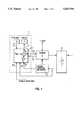
- FIG. 1is a block diagram of the charge information system 1 according to the invention.
- FIG. 2is a more detailed functional block diagram of the computing unit 5 in FIG. 1.
- the charge information system 1comprises a microcomputer 5 which, by means of an input unit 6, such as a keyboard, receives data from a user and displays the desired information by means of a display unit 7.
- the microcomputer 5also processes charger-related data 5.1 from the charger 2, charge condition data 5.2 from the charge condition determining device 3, additional battery-related data 5.3, such as the battery temperature, as well as vehicle-related and driving-condition-related data 5.4.
- the charger 2, charge condition detector 3 and other sensors for providing information to the microcomputer 5are of a conventional type known to those skilled in the art.
- the computing unit 5 in FIG. 1is programmed to perform a variety of calculations and controls 5a-5k, as shown in FIG. 2 and discussed in detail below.
- the charging conditions fed via the input unit 6can be transmitted by means of a data release command (for which, for example, a separate key may be provided on the keyboard) to the charger 2 as charge command data 5.5.
- a data release commandfor which, for example, a separate key may be provided on the keyboard
- the following sequencetakes place for the user of the charge information system according to the invention: First, corresponding to his wishes, in a dialogue with the computer, the user sets the battery charging parameters 8 for the charging operation. After these have been found and displayed on the display unit, the user starts the charging operation by operating the data release key.
- Various charging and operating parameters 8can be entered via the input unit 6, and the different information can be requested to determine the charging operation.
- the important monitoring functionis the display of the remaining required charging time t R ; that is, the time required to bring the battery from its present actual charging condition to a desired final charging condition, under defined charging parameters.
- t Rthe remaining required charging time
- a full charge (100% nominal capacity)will be desired.
- remaining charging time required to achieve a full chargewill be displayed first if no other input takes place by the user.
- the charging efficiency above 90% of the nominal capacityis substantially less than in the range of from 20% to 90%.
- the userVia the input unit 6, the user therefore also may indicate the desired charging efficiency (for example, 70%), whereupon the remaining charging time required for this purpose is displayed to him.
- a simple algorithm for calculating the remaining charging time in the case of a constant charging current Iis as follows: After the input of the charging efficiency, the desired charge Q des will be determined. The difference with respect to the actual charge Q act , which is provided by the charging condition determining device 3, results in the charge amount Q des -Q act to be charged. The remaining charging time t R is then obtained from the quotient:
- ⁇ Lis the charging efficiency
- the remaining charging timemay be calculated as follows: First, the computer unit 5 determines the desired charge Q des as a function of the defining quantities 8, by using relationships which are known per se. Subsequently, the computing unit 5 determines a charging diagram I t for the time variation of the charging current I which relates to Q des and the actual charging condition Q act , for example, by the selection of a stored charging diagram. As in the previously mentioned example, (in which the charging efficiency takes into account the characteristics of the battery 4), in this case the charging diagrams must be coordinated with the battery 4.
- the selection of the charging diagrammay also be influenced by additional battery charging parameters 8, such as for example, a maximal charging current.
- the computing unit 5determines the required remaining charging time t R to complete the charging operation, and emits a corresponding signal 9 to the display unit 7 so that the remaining charging time t R is displayed.
- the range of the electric-motor-driven vehiclewhich can be achieved by means of the selected charging efficiency, is also displayed.
- the range pertaining to the selected charging efficiencyis determined by the computer from a corresponding characteristic range--charging efficiency curve in a manner that is known, per se.
- the desired charging efficiencyis a function of the desired range
- the driverit is also possible for the driver to enter a desired range value instead of the charging efficiency. Then, by using the above-mentioned characteristic range--charging efficiency curve, the computer first determines the required charging efficiency, and then determines the remaining charging time therefrom. In addition to the remaining charging time, the required charging efficiency may also be displayed.
- the range which can be achieved by means of a particular charging efficiencydepends on many factors, especially on the driving speed, so that the above-mentioned characteristic range -charging efficiency curve can apply only to standard conditions. Therefore, in a preferred embodiment, it is further provided that the driver can input driving conditions which deviate from the standard. The computer then selects from a family of characteristic range--charging efficiency curves, one which corresponds to the specific driving conditions, and uses it to calculate the range or the charging efficiency.
- the family of characteristic range--charging efficiency curvesmay be parameterized according to the following driving conditions: the intended average driving speed or directional speed, the number of occupants of the vehicle, traffic conditions (city traffic, mixed cross-country traffic, express highway), the topography (flat, hilly, mountainous), etc.
- the driver's individual vehicle handling stylemay be taken into account, which was previously identified and stored, for example, by means of a learning program, as known, for example, from automatic transmissions.
- the recommended directional speedis determined by the computer and displayed. This directional speed should then be maintained by the driver in order to cover the given distance by means of the existing charge reserves.
- the charge reservesin this case may be based either on the desired charge reserves Q des or on the actual charging condition Q act .
- the display of a directional speed based on the actual charge reserves Q actis a function which is advantageous for the driver of the electrically driven vehicle, not only during the charging but also during the drive. As a result, the driver receives information as to how fast he may drive in order to cover a certain distance (for example, to the nearest charging station). In this case, the directional speed is continuously adapted to the actual situation.
- the maximal parking duration(after the passing of which a certain distance of, for example, 10 km, to the nearest charging station can just barely be driven in the emergency operation), represents another important control quantity.
- the maximal parking durationis also calculated and displayed. In this case, a simple algorithm is supplied by the quotient of the charge and the self-discharging current.
- Another useful control parameter which may be entered by the useris whether a quick charge is to be carried out because of a lack of time.
- a quick chargecauses a higher charging current, and thus the charging efficiency is less favorable; also, depending on the charging process, it also causes faster aging of the battery.
- the standardis an economical, careful but longer-lasting charging.
- the algorithm used for calculating the remaining charging time, and therefore the determined remaining charging time,are also based on this preliminary-decision for the charging current.
- the algorithm for calculating the remaining charging time t Rmay be modified in a manner that is known per se in order to better model the battery operations, for example, by taking into account the influence of the battery temperature on the charging efficiency.
- the computer 5may also receive the existing temperature conditions of the battery (battery-related data 5.3) and the outside temperature (driving-condition-related data 5.4) as well as the cooling outputs of the battery cooling and of the charge cooling. Thus, the lead time required to cool the battery sufficiently to start the charging operation may be calculated first.
- the charging operationwill be precalculated, in which case the temperature course of the battery is also taken into account, which influences the charging efficiency and a possibly required charging current limitation.
- the temperature course of the batteryin turn depends not only on the ohmic heat, but also on the current-dependent heat of reaction of the battery as well as the continuous cooling output.
- the display unit 7 and the input unit 6may advantageously be arranged in the interior of the vehicle in proximity to the driver.
- the displaymay have such a large format and will be illuminated such that it can be inspected from the outside.
- Imaging in a window paneis also possible, or an external display unit may be provided, as, for example, behind the cover for the roll-out mechanism of the supply cable to the external socket.
- an external displaymay also be provided, for example, in the display field of a stationary charging station. In the latter case, the data transmission may take place via the socket and the supply network, via radio or other remote control systems; in this manner it is also possible to query from inside a house.
- a combination with the remote operating system for the auxiliary heateris also possible.
- the display of other control quantitiesmay also be included in the charge information system.
- the previously consumed electric energy and the already run down charging timemay also be queried.
- an automatic display of the defect codetakes place; for example, current source without voltage; battery too hot; battery defective; excessively high charging current, etc.
- the charge information systemsupports the operator of the vehicle when he puts in the charge control parameters 8 at the start of a charging operation, during which the vehicle is parked and is connected to a charging station.
- the characteristics according to the invention in the case of a hybrid drivemay easily also be applied to the conditions during a combustion engine drive while the battery is charged at the same time.
- the charging current which can be supplied by the generatorwill then enter into the calculation of the remaining charging time.
Landscapes
- Engineering & Computer Science (AREA)
- Power Engineering (AREA)
- Transportation (AREA)
- Mechanical Engineering (AREA)
- Life Sciences & Earth Sciences (AREA)
- Sustainable Development (AREA)
- Sustainable Energy (AREA)
- General Physics & Mathematics (AREA)
- Physics & Mathematics (AREA)
- Manufacturing & Machinery (AREA)
- Chemical & Material Sciences (AREA)
- Chemical Kinetics & Catalysis (AREA)
- Electrochemistry (AREA)
- General Chemical & Material Sciences (AREA)
- Electric Propulsion And Braking For Vehicles (AREA)
Abstract
Description
t.sub.R =(Q.sub.des -Q.sub.act)/(I* η.sub.L)
Claims (15)
Applications Claiming Priority (2)
| Application Number | Priority Date | Filing Date | Title |
|---|---|---|---|
| DE4344368.0 | 1993-12-24 | ||
| DE4344368ADE4344368C1 (en) | 1993-12-24 | 1993-12-24 | Charge information system for an electrical or hybrid vehicle |
Publications (1)
| Publication Number | Publication Date |
|---|---|
| US5623194Atrue US5623194A (en) | 1997-04-22 |
Family
ID=6506133
Family Applications (1)
| Application Number | Title | Priority Date | Filing Date |
|---|---|---|---|
| US08/364,209Expired - Fee RelatedUS5623194A (en) | 1993-12-24 | 1994-12-27 | Apparatus for monitoring and controlling charging of a battery for a hybrid or electric vehicle |
Country Status (3)
| Country | Link |
|---|---|
| US (1) | US5623194A (en) |
| DE (1) | DE4344368C1 (en) |
| FR (1) | FR2714337B1 (en) |
Cited By (71)
| Publication number | Priority date | Publication date | Assignee | Title |
|---|---|---|---|---|
| US5790976A (en)* | 1995-05-24 | 1998-08-04 | Mercedes-Benz Ag | Route selection apparatus for a motor vehicle |
| US5867797A (en)* | 1994-12-27 | 1999-02-02 | Nec Corporation | Portable telephone set having a power controller causing a current charging of a battery to be held constant |
| US5892346A (en)* | 1995-02-27 | 1999-04-06 | Kabushikikaisha Equos Research | Vehicle |
| US5929609A (en)* | 1996-11-08 | 1999-07-27 | Alliedsignal Inc. | Vehicular power management system and method |
| US5939861A (en)* | 1996-05-24 | 1999-08-17 | Hino Jidosha Kogyo Kabushiki Kaisha | Control system for on-vehicle battery |
| EP0902520A3 (en)* | 1997-09-09 | 2000-03-08 | Matsushita Electric Industrial Co., Ltd. | Electric vehicle |
| US6494827B1 (en)* | 1998-10-29 | 2002-12-17 | Olympus Optical Co., Ltd. | Endoscope device and operation apparatus |
| US6526361B1 (en)* | 1997-06-19 | 2003-02-25 | Snap-On Equipment Limited | Battery testing and classification |
| US6534950B2 (en) | 2001-05-25 | 2003-03-18 | Cellex Power Products, Inc. | Hybrid power supply control system and method |
| US6559621B2 (en) | 2001-05-21 | 2003-05-06 | Cellex Power Products, Inc. | Hybrid energy storage device charge equalization system and method |
| US6583592B2 (en)* | 2000-08-04 | 2003-06-24 | Suzuki Motor Corporation | Control apparatus for hybrid vehicle |
| US6649290B2 (en) | 2001-05-11 | 2003-11-18 | Cellex Power Products, Inc. | Fuel cell thermal management system and method |
| US20030217876A1 (en)* | 1998-09-14 | 2003-11-27 | Paice Corporation | Hybrid vehicles |
| US20040044448A1 (en)* | 2002-08-27 | 2004-03-04 | Ford Motor Company | Vehicle systems controller with modular architecture |
| US6710575B2 (en)* | 2000-12-30 | 2004-03-23 | Hyundai Motor Company | Method for controlling a charging state of a battery for an electric vehicle |
| US20040245031A1 (en)* | 2001-02-16 | 2004-12-09 | Cellex Power Products, Inc. | Hybrid power supply apparatus for battery replacement applications |
| US20060052918A1 (en)* | 2002-03-18 | 2006-03-09 | Mcleod Paul W | Control and diagnostics system and method for vehicles |
| US20060071645A1 (en)* | 2004-09-27 | 2006-04-06 | Oshkosh Truck Corporation | Status indicator for an energy storage device for use with an electric vehicle |
| US20080249667A1 (en)* | 2007-04-09 | 2008-10-09 | Microsoft Corporation | Learning and reasoning to enhance energy efficiency in transportation systems |
| US20090043520A1 (en)* | 2006-08-10 | 2009-02-12 | V2Green, Inc. | User Interface and User Control in a Power Aggregation System for Distributed Electric Resources |
| US20090040032A1 (en)* | 2007-08-09 | 2009-02-12 | Allen Gerber | Hybrid drive mode indicator |
| US20090044996A1 (en)* | 2001-01-03 | 2009-02-19 | The Regents Of The University Of California | Method for controlling the operating characteristics of a hybrid electric vehicle |
| US20090114463A1 (en)* | 2007-06-12 | 2009-05-07 | Devault Robert C | Self-learning control system for plug-in hybrid vehicles |
| US20090157298A1 (en)* | 2007-12-12 | 2009-06-18 | Sony Corporation | Information processing apparatus, information providing method, program, and information providing system |
| US20090243549A1 (en)* | 2008-03-31 | 2009-10-01 | Naoki Matsumura | Intelligent battery charging rate management |
| US20090302801A1 (en)* | 2008-06-06 | 2009-12-10 | Kabushiki Kaisha Toyota Jidoshokki | Charging system and vehicle and charge controller for the charging system |
| US20100019726A1 (en)* | 2008-07-24 | 2010-01-28 | General Electric Company | Method and system for control of a vehicle energy storage device |
| US20100019718A1 (en)* | 2008-07-24 | 2010-01-28 | General Electric Company | Method and system for extending life of a vehicle energy storage device |
| US20100082190A1 (en)* | 2007-01-16 | 2010-04-01 | Toyota Jisosha Kabushiki Kaisha | Vehicle and control method thereof |
| US20100138098A1 (en)* | 2007-07-19 | 2010-06-03 | Masatoshi Takahara | Map display apparatus, map display method, and computer-readable tangible medium |
| US20100230193A1 (en)* | 2009-03-12 | 2010-09-16 | Ford Global Technologies, Llc | Plug-in vehicle function indication |
| US20100238006A1 (en)* | 2009-03-17 | 2010-09-23 | Ford Global Technologies, Llc | Concealed display for an external surface of a vehicle |
| US20100265050A1 (en)* | 2009-04-17 | 2010-10-21 | Ford Global Technologies, Llc | Vehicle Information Display And Method |
| US20110095878A1 (en)* | 2009-10-22 | 2011-04-28 | Ford Global Technologies, Llc | Vehicle Information Display And Method |
| US20110127951A1 (en)* | 2009-11-30 | 2011-06-02 | Broadcom Corporation | Device with integrated wireless power receiver |
| US20110184642A1 (en)* | 2009-12-18 | 2011-07-28 | Daimler Trucks North America Llc | Fuel efficient routing system and method |
| CN102341988A (en)* | 2009-03-03 | 2012-02-01 | Rwe股份公司 | Method and apparatus for charging electric vehicles |
| WO2012007817A3 (en)* | 2010-07-16 | 2012-06-07 | Toyota Jidosha Kabushiki Kaisha | Electricity charging system |
| US20120143413A1 (en)* | 2010-12-03 | 2012-06-07 | Kia Motors Corporation | Device and method for calculating distance to empty of electric vehicle |
| US20130134940A1 (en)* | 2010-08-09 | 2013-05-30 | Sanyo Electric Co., Ltd. | Power control apparatus |
| US20130231818A1 (en)* | 2010-11-15 | 2013-09-05 | Mitsubishi Jidosha Kogyo Kabushiki Kaisha | Charging control apparatus for electric vehicle |
| US8538686B2 (en) | 2011-09-09 | 2013-09-17 | Microsoft Corporation | Transport-dependent prediction of destinations |
| US20140042985A1 (en)* | 2011-05-11 | 2014-02-13 | Toyota Jidosha Kabushiki Kaisha | Charging control device, vehicle including the same and charging control method |
| US8725330B2 (en) | 2010-06-02 | 2014-05-13 | Bryan Marc Failing | Increasing vehicle security |
| GB2510124A (en)* | 2013-01-24 | 2014-07-30 | Jaguar Land Rover Ltd | Electric vehicle with externally visible charging indication |
| US8981590B2 (en) | 2011-05-28 | 2015-03-17 | Audi Ag | Hybrid vehicle and method for operating a device for charging a battery in a hybrid vehicle |
| US9114181B2 (en) | 2011-03-30 | 2015-08-25 | Covidien Lp | Process of cooling surgical device battery before or during high temperature sterilization |
| US20150321570A1 (en)* | 2014-05-08 | 2015-11-12 | Honda Motor Co., Ltd. | Electric vehicle charging control system |
| US9296302B2 (en) | 2009-08-11 | 2016-03-29 | Continental Automotive Gmbh | Charging device for an energy store and method for operating such a charging device |
| US20160129918A1 (en)* | 2014-11-10 | 2016-05-12 | Ford Global Technologies, Llc | Electric Range Impact Factor Display and Algorithms |
| EP2543970A3 (en)* | 2011-07-06 | 2016-05-18 | Clarion Co., Ltd. | Information terminal and cruise controller for electric-powered vehicle |
| US9429657B2 (en) | 2011-12-14 | 2016-08-30 | Microsoft Technology Licensing, Llc | Power efficient activation of a device movement sensor module |
| US9464903B2 (en) | 2011-07-14 | 2016-10-11 | Microsoft Technology Licensing, Llc | Crowd sourcing based on dead reckoning |
| US9470529B2 (en) | 2011-07-14 | 2016-10-18 | Microsoft Technology Licensing, Llc | Activating and deactivating sensors for dead reckoning |
| CN106585386A (en)* | 2015-10-19 | 2017-04-26 | 北京新能源汽车股份有限公司 | Driving range display method, device and system of electric automobile |
| US9832749B2 (en) | 2011-06-03 | 2017-11-28 | Microsoft Technology Licensing, Llc | Low accuracy positional data by detecting improbable samples |
| US10030988B2 (en) | 2010-12-17 | 2018-07-24 | Uber Technologies, Inc. | Mobile search based on predicted location |
| US10040361B2 (en) | 2013-01-24 | 2018-08-07 | Jaguar Land Rover Limited | Methods and apparatus for indicating charging status of a vehicle |
| US20180260887A1 (en)* | 2015-11-17 | 2018-09-13 | Omron Corporation | Battery reservation device |
| US10184798B2 (en) | 2011-10-28 | 2019-01-22 | Microsoft Technology Licensing, Llc | Multi-stage dead reckoning for crowd sourcing |
| US20190305382A1 (en)* | 2018-03-29 | 2019-10-03 | Mohamed Khaled Morsy | User-Defined Battery Recharging Systems and Methods |
| US10600116B2 (en) | 2015-11-17 | 2020-03-24 | Omron Corporation | Reservation management device, reservation management system, and reservation management method |
| US10650444B2 (en) | 2015-11-17 | 2020-05-12 | Omron Corporation | Battery reservation device and battery reservation method |
| US10746561B2 (en) | 2005-09-29 | 2020-08-18 | Microsoft Technology Licensing, Llc | Methods for predicting destinations from partial trajectories employing open- and closed-world modeling methods |
| WO2020198118A1 (en)* | 2019-03-27 | 2020-10-01 | EnerSys Delaware, Inc. | Methods, systems, and devices for estimating and predicting a remaining time to charge and a remaining time to discharge of a battery |
| US11010824B2 (en) | 2015-11-17 | 2021-05-18 | Omron Corporation | Battery reservation device and battery reservation method |
| CN113442790A (en)* | 2020-03-25 | 2021-09-28 | 奥迪股份公司 | Method for operating a vehicle electrically driven by means of a battery, and vehicle having a battery and a control unit |
| US11186165B2 (en)* | 2019-01-28 | 2021-11-30 | Honda Motor Co., Ltd. | Heat distribution device for hybrid vehicle |
| US20220048401A1 (en)* | 2020-08-12 | 2022-02-17 | Dr. Ing. H.C. F. Porsche Aktiengesellschaft | Method for carrying out a charging process of a vehicle-external charging apparatus for charging a vehicle, and charging apparatus |
| DE102015200933B4 (en) | 2015-01-21 | 2022-04-21 | Bayerische Motoren Werke Aktiengesellschaft | Use of waste heat from an inductive coil |
| US11563338B1 (en) | 2008-07-11 | 2023-01-24 | Charge Fusion Technologies, Llc | Systems and methods for electric vehicle charging and power management |
Families Citing this family (13)
| Publication number | Priority date | Publication date | Assignee | Title |
|---|---|---|---|---|
| DE19912300A1 (en)* | 1999-03-19 | 2000-09-21 | Bosch Gmbh Robert | method |
| DE102009016624A1 (en)* | 2009-04-08 | 2010-09-09 | Rwe Ag | Method for charging electric vehicles, involves connecting electric vehicle with charging station for obtaining electricity, where charging of battery and desired charging duration of vehicle are determined |
| DE102009013806A1 (en)* | 2009-03-18 | 2010-09-23 | Webasto Ag | Radio remote control for motor vehicle, has display device, where radio remote control is connected with motor vehicle by bi-directional radio connection |
| DE102009023535B4 (en)* | 2009-05-30 | 2025-06-18 | Bayerische Motoren Werke Aktiengesellschaft | Vehicle with an electric drive and method for operating a vehicle |
| DE102009052927A1 (en)* | 2009-11-12 | 2011-05-19 | Bayerische Motoren Werke Aktiengesellschaft | Motor vehicle has electric drive and electrical energy storage for supplying electric drive with power, where loading interface is provided for loading energy storage with electrical energy |
| DE102010037275A1 (en)* | 2010-09-02 | 2012-03-08 | Dr. Ing. H.C. F. Porsche Aktiengesellschaft | Operating device, control system and method for a plug-in motor vehicle |
| KR101181186B1 (en) | 2010-10-20 | 2012-09-18 | 현대자동차주식회사 | Telematics of Electric Vehicle for Remote HVAC Control and Its Remote HVAC Control Method |
| DE102011104258A1 (en) | 2010-11-19 | 2012-05-24 | Audi Ag | Method for determining a partial area of a map and motor vehicle describing the remaining range of a motor vehicle |
| DE102011121725A1 (en)* | 2011-12-20 | 2013-06-20 | GM Global Technology Operations LLC (n. d. Gesetzen des Staates Delaware) | Mobile device e.g. smart phone for displaying current range of electric car, has calculation unit that is arranged to calculate current range of electric car based on vehicle data and determined charging time period |
| DE102016004360B3 (en)* | 2016-04-09 | 2017-08-10 | Audi Ag | Method for controlling an energy storage device of a mild hybrid motor vehicle and state of charge control device and motor vehicle with such a state of charge control device |
| DE102018206032A1 (en)* | 2018-04-20 | 2019-10-24 | Robert Bosch Gmbh | Method for charging an electrical energy storage unit |
| DE102019219502A1 (en)* | 2019-12-12 | 2021-06-17 | Robert Bosch Gmbh | Method for determining a remaining charging time of a battery system with at least one battery module and a battery system for carrying out such a method |
| DE102021116691A1 (en) | 2021-04-20 | 2022-10-20 | Dr. Ing. H.C. F. Porsche Aktiengesellschaft | electric vehicle |
Citations (4)
| Publication number | Priority date | Publication date | Assignee | Title |
|---|---|---|---|---|
| DE3220152A1 (en)* | 1981-05-30 | 1982-12-16 | Lucas Industries P.L.C., Birmingham, West Midlands | BATTERY CHARGER |
| DE3142038A1 (en)* | 1981-10-23 | 1983-05-05 | GES Gesellschaft für elektrischen Straßenverkehr mbH, 4300 Essen | Method and arrangement for determining the remaining driving range in an electric vehicle |
| DE3321045A1 (en)* | 1982-06-12 | 1983-12-15 | Lucas Industries Ltd., Birmingham, West Midlands | METHOD AND DEVICE FOR DETERMINING THE CHARGE STATE OF A BATTERY |
| DE4116899A1 (en)* | 1990-05-23 | 1991-11-28 | Nissan Motor | ELECTRIC VEHICLE |
- 1993
- 1993-12-24DEDE4344368Apatent/DE4344368C1/ennot_activeExpired - Fee Related
- 1994
- 1994-12-22FRFR9415479Apatent/FR2714337B1/ennot_activeExpired - Fee Related
- 1994-12-27USUS08/364,209patent/US5623194A/ennot_activeExpired - Fee Related
Patent Citations (7)
| Publication number | Priority date | Publication date | Assignee | Title |
|---|---|---|---|---|
| DE3220152A1 (en)* | 1981-05-30 | 1982-12-16 | Lucas Industries P.L.C., Birmingham, West Midlands | BATTERY CHARGER |
| US4435675A (en)* | 1981-05-30 | 1984-03-06 | Lucas Industries Plc. | Battery charging system |
| DE3142038A1 (en)* | 1981-10-23 | 1983-05-05 | GES Gesellschaft für elektrischen Straßenverkehr mbH, 4300 Essen | Method and arrangement for determining the remaining driving range in an electric vehicle |
| DE3321045A1 (en)* | 1982-06-12 | 1983-12-15 | Lucas Industries Ltd., Birmingham, West Midlands | METHOD AND DEVICE FOR DETERMINING THE CHARGE STATE OF A BATTERY |
| US4558281A (en)* | 1982-06-12 | 1985-12-10 | Lucas Industries | Battery state of charge evaluator |
| DE4116899A1 (en)* | 1990-05-23 | 1991-11-28 | Nissan Motor | ELECTRIC VEHICLE |
| US5212431A (en)* | 1990-05-23 | 1993-05-18 | Nissan Motor Co., Ltd. | Electric vehicle |
Non-Patent Citations (1)
| Title |
|---|
| French Search Report dated Mar. 13, 1996.* |
Cited By (125)
| Publication number | Priority date | Publication date | Assignee | Title |
|---|---|---|---|---|
| US5867797A (en)* | 1994-12-27 | 1999-02-02 | Nec Corporation | Portable telephone set having a power controller causing a current charging of a battery to be held constant |
| US5892346A (en)* | 1995-02-27 | 1999-04-06 | Kabushikikaisha Equos Research | Vehicle |
| US5790976A (en)* | 1995-05-24 | 1998-08-04 | Mercedes-Benz Ag | Route selection apparatus for a motor vehicle |
| US5939861A (en)* | 1996-05-24 | 1999-08-17 | Hino Jidosha Kogyo Kabushiki Kaisha | Control system for on-vehicle battery |
| US5929609A (en)* | 1996-11-08 | 1999-07-27 | Alliedsignal Inc. | Vehicular power management system and method |
| US6526361B1 (en)* | 1997-06-19 | 2003-02-25 | Snap-On Equipment Limited | Battery testing and classification |
| US6232743B1 (en) | 1997-09-09 | 2001-05-15 | Matsushita Electric Industrial Co., Ltd. | Electric vehicle |
| EP0902520A3 (en)* | 1997-09-09 | 2000-03-08 | Matsushita Electric Industrial Co., Ltd. | Electric vehicle |
| US7520353B2 (en) | 1998-09-14 | 2009-04-21 | Paice Llc | Hybrid vehicle configuration |
| US7104347B2 (en) | 1998-09-14 | 2006-09-12 | Paice Llc | Hybrid vehicles |
| US7455134B2 (en) | 1998-09-14 | 2008-11-25 | Paice Llc | Hybrid vehicles |
| US7392871B2 (en) | 1998-09-14 | 2008-07-01 | Paice Llc | Hybrid vehicles |
| US7237634B2 (en) | 1998-09-14 | 2007-07-03 | Paice Llc | Hybrid vehicles |
| US20030217876A1 (en)* | 1998-09-14 | 2003-11-27 | Paice Corporation | Hybrid vehicles |
| US6494827B1 (en)* | 1998-10-29 | 2002-12-17 | Olympus Optical Co., Ltd. | Endoscope device and operation apparatus |
| US6583592B2 (en)* | 2000-08-04 | 2003-06-24 | Suzuki Motor Corporation | Control apparatus for hybrid vehicle |
| US6710575B2 (en)* | 2000-12-30 | 2004-03-23 | Hyundai Motor Company | Method for controlling a charging state of a battery for an electric vehicle |
| US20090044996A1 (en)* | 2001-01-03 | 2009-02-19 | The Regents Of The University Of California | Method for controlling the operating characteristics of a hybrid electric vehicle |
| US20070199746A1 (en)* | 2001-02-16 | 2007-08-30 | Cellex Power Products, Inc. | Hybrid power supply apparatus for battery replacement applications |
| US20040245031A1 (en)* | 2001-02-16 | 2004-12-09 | Cellex Power Products, Inc. | Hybrid power supply apparatus for battery replacement applications |
| US7207405B2 (en) | 2001-02-16 | 2007-04-24 | Cellex Power Products, Inc. | Hybrid power supply apparatus for battery replacement applications |
| US6649290B2 (en) | 2001-05-11 | 2003-11-18 | Cellex Power Products, Inc. | Fuel cell thermal management system and method |
| US6559621B2 (en) | 2001-05-21 | 2003-05-06 | Cellex Power Products, Inc. | Hybrid energy storage device charge equalization system and method |
| US6534950B2 (en) | 2001-05-25 | 2003-03-18 | Cellex Power Products, Inc. | Hybrid power supply control system and method |
| US7778746B2 (en)* | 2002-03-18 | 2010-08-17 | Club Car, Inc. | Control and diagnostics system and method for vehicles |
| US20060052918A1 (en)* | 2002-03-18 | 2006-03-09 | Mcleod Paul W | Control and diagnostics system and method for vehicles |
| US20040044448A1 (en)* | 2002-08-27 | 2004-03-04 | Ford Motor Company | Vehicle systems controller with modular architecture |
| US20060071645A1 (en)* | 2004-09-27 | 2006-04-06 | Oshkosh Truck Corporation | Status indicator for an energy storage device for use with an electric vehicle |
| US7439711B2 (en) | 2004-09-27 | 2008-10-21 | Oshkosh Corporation | Energy storage device including a status indicator |
| US10746561B2 (en) | 2005-09-29 | 2020-08-18 | Microsoft Technology Licensing, Llc | Methods for predicting destinations from partial trajectories employing open- and closed-world modeling methods |
| US20090043520A1 (en)* | 2006-08-10 | 2009-02-12 | V2Green, Inc. | User Interface and User Control in a Power Aggregation System for Distributed Electric Resources |
| US20100082190A1 (en)* | 2007-01-16 | 2010-04-01 | Toyota Jisosha Kabushiki Kaisha | Vehicle and control method thereof |
| US8577526B2 (en)* | 2007-01-16 | 2013-11-05 | Toyota Jidosha Kabushiki Kaisha | Vehicle and control method thereof |
| US20080249667A1 (en)* | 2007-04-09 | 2008-10-09 | Microsoft Corporation | Learning and reasoning to enhance energy efficiency in transportation systems |
| US7849944B2 (en)* | 2007-06-12 | 2010-12-14 | Ut-Battelle, Llc | Self-learning control system for plug-in hybrid vehicles |
| US20090114463A1 (en)* | 2007-06-12 | 2009-05-07 | Devault Robert C | Self-learning control system for plug-in hybrid vehicles |
| US20100138098A1 (en)* | 2007-07-19 | 2010-06-03 | Masatoshi Takahara | Map display apparatus, map display method, and computer-readable tangible medium |
| US8417401B2 (en) | 2007-07-19 | 2013-04-09 | Aisin Aw Co., Ltd. | Map display apparatus, map display method, and computer-readable tangible medium |
| US20090040032A1 (en)* | 2007-08-09 | 2009-02-12 | Allen Gerber | Hybrid drive mode indicator |
| US7893822B2 (en)* | 2007-08-09 | 2011-02-22 | Allen Gerber | Hybrid drive mode indicator |
| US20090157298A1 (en)* | 2007-12-12 | 2009-06-18 | Sony Corporation | Information processing apparatus, information providing method, program, and information providing system |
| US8121779B2 (en)* | 2007-12-12 | 2012-02-21 | Sony Corporation | Information processing apparatus, information providing method, program, and information providing system |
| US20090243549A1 (en)* | 2008-03-31 | 2009-10-01 | Naoki Matsumura | Intelligent battery charging rate management |
| AU2009202248B2 (en)* | 2008-06-06 | 2011-09-01 | Kabushiki Kaisha Toyota Jidoshokki | Charging system and vehicle and charge controller for the charging system |
| US8125183B2 (en) | 2008-06-06 | 2012-02-28 | Kabushiki Kaisha Toyota Jidoshokki | Charging system and vehicle and charge controller for the charging system |
| US20090302801A1 (en)* | 2008-06-06 | 2009-12-10 | Kabushiki Kaisha Toyota Jidoshokki | Charging system and vehicle and charge controller for the charging system |
| US11563338B1 (en) | 2008-07-11 | 2023-01-24 | Charge Fusion Technologies, Llc | Systems and methods for electric vehicle charging and power management |
| US11631987B2 (en) | 2008-07-11 | 2023-04-18 | Charge Fusion Technologies, Llc | Systems and methods for charging electric vehicles |
| US11575275B1 (en) | 2008-07-11 | 2023-02-07 | Charge Fusion Technologies, Llc | Systems and methods for electric vehicle charging and power management |
| US11990788B2 (en) | 2008-07-11 | 2024-05-21 | Charge Fusion Technologies, Llc | Systems and methods for graphical user interface (GUI)-based charging of electric vehicles |
| US12289010B2 (en) | 2008-07-11 | 2025-04-29 | Charge Fusion Technologies, Llc | Systems and methods for bi-directional, reverse, and cooperative charging of electric vehicles |
| US8587260B2 (en) | 2008-07-24 | 2013-11-19 | General Electric Company | Method and system for control of a vehicle energy storage device |
| US8063609B2 (en) | 2008-07-24 | 2011-11-22 | General Electric Company | Method and system for extending life of a vehicle energy storage device |
| US20100019718A1 (en)* | 2008-07-24 | 2010-01-28 | General Electric Company | Method and system for extending life of a vehicle energy storage device |
| US8212532B2 (en) | 2008-07-24 | 2012-07-03 | General Electric Company | Method and system for control of a vehicle energy storage device |
| US20100019726A1 (en)* | 2008-07-24 | 2010-01-28 | General Electric Company | Method and system for control of a vehicle energy storage device |
| CN102341988A (en)* | 2009-03-03 | 2012-02-01 | Rwe股份公司 | Method and apparatus for charging electric vehicles |
| CN102341988B (en)* | 2009-03-03 | 2015-01-07 | Rwe股份公司 | Method and apparatus for charging electric vehicles |
| JP2012519466A (en)* | 2009-03-03 | 2012-08-23 | アール・ヴェー・エー アクチェンゲゼルシャフト | Electric vehicle charging method and charging device |
| US20100230193A1 (en)* | 2009-03-12 | 2010-09-16 | Ford Global Technologies, Llc | Plug-in vehicle function indication |
| US20100238006A1 (en)* | 2009-03-17 | 2010-09-23 | Ford Global Technologies, Llc | Concealed display for an external surface of a vehicle |
| US20100265050A1 (en)* | 2009-04-17 | 2010-10-21 | Ford Global Technologies, Llc | Vehicle Information Display And Method |
| US8120478B2 (en) | 2009-04-17 | 2012-02-21 | Ford Global Technologies, Llc | Vehicle information display and method |
| US9296302B2 (en) | 2009-08-11 | 2016-03-29 | Continental Automotive Gmbh | Charging device for an energy store and method for operating such a charging device |
| US9506781B2 (en) | 2009-10-22 | 2016-11-29 | Ford Global Technologies, Llc | Vehicle information display and method |
| US20110095878A1 (en)* | 2009-10-22 | 2011-04-28 | Ford Global Technologies, Llc | Vehicle Information Display And Method |
| US9590444B2 (en)* | 2009-11-30 | 2017-03-07 | Broadcom Corporation | Device with integrated wireless power receiver configured to make a charging determination based on a level of battery life and charging efficiency |
| US20110127951A1 (en)* | 2009-11-30 | 2011-06-02 | Broadcom Corporation | Device with integrated wireless power receiver |
| US20110184642A1 (en)* | 2009-12-18 | 2011-07-28 | Daimler Trucks North America Llc | Fuel efficient routing system and method |
| US8841881B2 (en) | 2010-06-02 | 2014-09-23 | Bryan Marc Failing | Energy transfer with vehicles |
| US11186192B1 (en) | 2010-06-02 | 2021-11-30 | Bryan Marc Failing | Improving energy transfer with vehicles |
| US8725330B2 (en) | 2010-06-02 | 2014-05-13 | Bryan Marc Failing | Increasing vehicle security |
| US10124691B1 (en) | 2010-06-02 | 2018-11-13 | Bryan Marc Failing | Energy transfer with vehicles |
| US9114719B1 (en) | 2010-06-02 | 2015-08-25 | Bryan Marc Failing | Increasing vehicle security |
| US9393878B1 (en) | 2010-06-02 | 2016-07-19 | Bryan Marc Failing | Energy transfer with vehicles |
| WO2012007817A3 (en)* | 2010-07-16 | 2012-06-07 | Toyota Jidosha Kabushiki Kaisha | Electricity charging system |
| CN103003092A (en)* | 2010-07-16 | 2013-03-27 | 丰田自动车株式会社 | charging system |
| US9160193B2 (en)* | 2010-07-16 | 2015-10-13 | Toyota Jidosha Kabushiki Kaisha | Electricity charging system |
| US20130141054A1 (en)* | 2010-07-16 | 2013-06-06 | Toyota Jidosha Kabushiki Kaisha | Electricity charging system |
| CN103003092B (en)* | 2010-07-16 | 2015-12-09 | 丰田自动车株式会社 | charging system |
| US20130134940A1 (en)* | 2010-08-09 | 2013-05-30 | Sanyo Electric Co., Ltd. | Power control apparatus |
| US20130231818A1 (en)* | 2010-11-15 | 2013-09-05 | Mitsubishi Jidosha Kogyo Kabushiki Kaisha | Charging control apparatus for electric vehicle |
| US8880264B2 (en)* | 2010-11-15 | 2014-11-04 | Mitsubishi Jidosha Kabushiki Kaisha | Charging control apparatus for electric vehicle |
| US8798831B2 (en)* | 2010-12-03 | 2014-08-05 | Hyundai Motor Company | Device and method for calculating distance to empty of electric vehicle |
| US20120143413A1 (en)* | 2010-12-03 | 2012-06-07 | Kia Motors Corporation | Device and method for calculating distance to empty of electric vehicle |
| US10935389B2 (en) | 2010-12-17 | 2021-03-02 | Uber Technologies, Inc. | Mobile search based on predicted location |
| US12078501B2 (en) | 2010-12-17 | 2024-09-03 | Uber Technologies, Inc. | Mobile search based on predicted location |
| US11614336B2 (en) | 2010-12-17 | 2023-03-28 | Uber Technologies, Inc. | Mobile search based on predicted location |
| US10030988B2 (en) | 2010-12-17 | 2018-07-24 | Uber Technologies, Inc. | Mobile search based on predicted location |
| US9114181B2 (en) | 2011-03-30 | 2015-08-25 | Covidien Lp | Process of cooling surgical device battery before or during high temperature sterilization |
| US9265847B2 (en) | 2011-03-30 | 2016-02-23 | Covidien Lp | Process of cooling surgical device battery before or during high temperature sterilization |
| US20140042985A1 (en)* | 2011-05-11 | 2014-02-13 | Toyota Jidosha Kabushiki Kaisha | Charging control device, vehicle including the same and charging control method |
| US8896267B2 (en)* | 2011-05-11 | 2014-11-25 | Toyota Jidosha Kabushiki Kaisha | Charging control device, vehicle including the same and charging control method |
| US8981590B2 (en) | 2011-05-28 | 2015-03-17 | Audi Ag | Hybrid vehicle and method for operating a device for charging a battery in a hybrid vehicle |
| US9832749B2 (en) | 2011-06-03 | 2017-11-28 | Microsoft Technology Licensing, Llc | Low accuracy positional data by detecting improbable samples |
| EP2543970A3 (en)* | 2011-07-06 | 2016-05-18 | Clarion Co., Ltd. | Information terminal and cruise controller for electric-powered vehicle |
| US9470529B2 (en) | 2011-07-14 | 2016-10-18 | Microsoft Technology Licensing, Llc | Activating and deactivating sensors for dead reckoning |
| US9464903B2 (en) | 2011-07-14 | 2016-10-11 | Microsoft Technology Licensing, Llc | Crowd sourcing based on dead reckoning |
| US10082397B2 (en) | 2011-07-14 | 2018-09-25 | Microsoft Technology Licensing, Llc | Activating and deactivating sensors for dead reckoning |
| US8538686B2 (en) | 2011-09-09 | 2013-09-17 | Microsoft Corporation | Transport-dependent prediction of destinations |
| US10184798B2 (en) | 2011-10-28 | 2019-01-22 | Microsoft Technology Licensing, Llc | Multi-stage dead reckoning for crowd sourcing |
| US9429657B2 (en) | 2011-12-14 | 2016-08-30 | Microsoft Technology Licensing, Llc | Power efficient activation of a device movement sensor module |
| US10040361B2 (en) | 2013-01-24 | 2018-08-07 | Jaguar Land Rover Limited | Methods and apparatus for indicating charging status of a vehicle |
| GB2510124B (en)* | 2013-01-24 | 2016-01-06 | Jaguar Land Rover Ltd | Charging indicator |
| GB2510124A (en)* | 2013-01-24 | 2014-07-30 | Jaguar Land Rover Ltd | Electric vehicle with externally visible charging indication |
| US10552923B2 (en)* | 2014-05-08 | 2020-02-04 | Honda Motor Co., Ltd. | Electric vehicle charging control system |
| US20150321570A1 (en)* | 2014-05-08 | 2015-11-12 | Honda Motor Co., Ltd. | Electric vehicle charging control system |
| US9776643B2 (en)* | 2014-11-10 | 2017-10-03 | Ford Global Technologies, Llc | Electric range impact factor display and algorithms |
| CN105584438B (en)* | 2014-11-10 | 2020-08-07 | 福特全球技术公司 | Display and algorithm of electric mileage influence factors |
| CN105584438A (en)* | 2014-11-10 | 2016-05-18 | 福特全球技术公司 | Electric range impact factor display and algorithms |
| US20160129918A1 (en)* | 2014-11-10 | 2016-05-12 | Ford Global Technologies, Llc | Electric Range Impact Factor Display and Algorithms |
| DE102015200933B4 (en) | 2015-01-21 | 2022-04-21 | Bayerische Motoren Werke Aktiengesellschaft | Use of waste heat from an inductive coil |
| CN106585386A (en)* | 2015-10-19 | 2017-04-26 | 北京新能源汽车股份有限公司 | Driving range display method, device and system of electric automobile |
| US11010824B2 (en) | 2015-11-17 | 2021-05-18 | Omron Corporation | Battery reservation device and battery reservation method |
| US10650444B2 (en) | 2015-11-17 | 2020-05-12 | Omron Corporation | Battery reservation device and battery reservation method |
| US10643272B2 (en)* | 2015-11-17 | 2020-05-05 | Omron Corporation | Battery reservation device |
| US10600116B2 (en) | 2015-11-17 | 2020-03-24 | Omron Corporation | Reservation management device, reservation management system, and reservation management method |
| US20180260887A1 (en)* | 2015-11-17 | 2018-09-13 | Omron Corporation | Battery reservation device |
| US11862772B2 (en)* | 2018-03-29 | 2024-01-02 | Canal Electronics LLC | User-defined battery recharging systems and methods |
| US20190305382A1 (en)* | 2018-03-29 | 2019-10-03 | Mohamed Khaled Morsy | User-Defined Battery Recharging Systems and Methods |
| US11186165B2 (en)* | 2019-01-28 | 2021-11-30 | Honda Motor Co., Ltd. | Heat distribution device for hybrid vehicle |
| WO2020198118A1 (en)* | 2019-03-27 | 2020-10-01 | EnerSys Delaware, Inc. | Methods, systems, and devices for estimating and predicting a remaining time to charge and a remaining time to discharge of a battery |
| CN113442790A (en)* | 2020-03-25 | 2021-09-28 | 奥迪股份公司 | Method for operating a vehicle electrically driven by means of a battery, and vehicle having a battery and a control unit |
| US20220048401A1 (en)* | 2020-08-12 | 2022-02-17 | Dr. Ing. H.C. F. Porsche Aktiengesellschaft | Method for carrying out a charging process of a vehicle-external charging apparatus for charging a vehicle, and charging apparatus |
| US12162371B2 (en)* | 2020-08-12 | 2024-12-10 | Dr. Ing. H. C. F. Porsche Ag | Method and apparatus for determining a price of a charging process of a vehicle |
Also Published As
| Publication number | Publication date |
|---|---|
| FR2714337B1 (en) | 1997-01-24 |
| FR2714337A1 (en) | 1995-06-30 |
| DE4344368C1 (en) | 1995-05-11 |
Similar Documents
| Publication | Publication Date | Title |
|---|---|---|
| US5623194A (en) | Apparatus for monitoring and controlling charging of a battery for a hybrid or electric vehicle | |
| US5426589A (en) | Method of and apparatus for limiting electrical loads on an electric vehicle | |
| USRE40820E1 (en) | Multi-battery fuel saving and emissions reduction system for automotive vehicles | |
| US6466024B1 (en) | Multi-battery fuel saving and emission reduction system for automotive vehicles | |
| US5699050A (en) | Battery capacity meter | |
| EP1020319B1 (en) | Assist device for use in electric vehicle | |
| US8116973B2 (en) | Vehicular display device, method of controlling the same, program, and storage medium having program stored therein | |
| US4405891A (en) | Control system for electric powered vehicle | |
| US6925369B2 (en) | Automotive power distribution apparatus and auxiliary terminal for a user optional load | |
| US7521935B2 (en) | Powertrain battery life predicting and warning apparatuses | |
| US5659240A (en) | Intelligent battery charger for electric drive system batteries | |
| US7259664B1 (en) | Sensorless fuel level and oil change indicators | |
| CN1953886B (en) | Information display and method of displaying information for a vehicle | |
| US20130166123A1 (en) | Vehicle system for estimating travel range | |
| JPH08507671A (en) | Energy management system for vehicles with finite energy storage | |
| CN116635264A (en) | Method and device for providing a reserve of storage capacity in a traction battery for an upcoming downhill drive | |
| CN103660978A (en) | Vehicle | |
| US12024058B2 (en) | Method for operating a battery of a parked motor vehicle, and motor vehicle | |
| CN115635881B (en) | Intelligent battery management method for new energy vehicles | |
| US20220161681A1 (en) | Method for determining a maximum value for a parameter range of a driving operation parameter of a motor vehicle and motor vehicle | |
| WO2009020217A1 (en) | Storage battery device equipped car and thermal control method of storage battery device | |
| CN101380950A (en) | Method and apparatus for managing power flow of an electric power storage device | |
| EP0784800B1 (en) | Motor vehicle battery circuit comprising monitoring of discharge and recharge current | |
| JP2003264906A (en) | Battery control system for automobile | |
| JP3288927B2 (en) | In-vehicle battery display |
Legal Events
| Date | Code | Title | Description |
|---|---|---|---|
| AS | Assignment | Owner name:MERCEDES-BENZ AG, GERMANY Free format text:ASSIGNMENT OF ASSIGNORS INTEREST;ASSIGNORS:BOLL, WOLF;KNORZER, GUNTHER;MIKULIC, LEOPOLD;REEL/FRAME:007350/0321;SIGNING DATES FROM 19950113 TO 19950117 | |
| AS | Assignment | Owner name:DAIMLER-BENZ AKTIENGESELLSCHAFT, GERMANY Free format text:MERGER RE-RECORD TO CORRECT THE NUMBER OF MICROFILM PAGES FROM 60 TO 98 AT REEL 9360, FRAME 0937.;ASSIGNOR:MERCEDES-BENZ AG;REEL/FRAME:009827/0145 Effective date:19970605 Owner name:DAIMLER-BENZ AKTIENGESELLSCHAFT, GERMANY Free format text:MERGER;ASSIGNOR:MERCEDES-BENZ AG;REEL/FRAME:009360/0937 Effective date:19970605 | |
| AS | Assignment | Owner name:DAIMLERCHRYSLER AG, GERMANY Free format text:MERGER;ASSIGNOR:DAIMLER-BENZ AKTIENGESELLSCHAFT;REEL/FRAME:010133/0556 Effective date:19990108 | |
| FEPP | Fee payment procedure | Free format text:PAYOR NUMBER ASSIGNED (ORIGINAL EVENT CODE: ASPN); ENTITY STATUS OF PATENT OWNER: LARGE ENTITY | |
| FPAY | Fee payment | Year of fee payment:4 | |
| FPAY | Fee payment | Year of fee payment:8 | |
| REMI | Maintenance fee reminder mailed | ||
| LAPS | Lapse for failure to pay maintenance fees | ||
| LAPS | Lapse for failure to pay maintenance fees | Free format text:PATENT EXPIRED FOR FAILURE TO PAY MAINTENANCE FEES (ORIGINAL EVENT CODE: EXP.); ENTITY STATUS OF PATENT OWNER: LARGE ENTITY | |
| STCH | Information on status: patent discontinuation | Free format text:PATENT EXPIRED DUE TO NONPAYMENT OF MAINTENANCE FEES UNDER 37 CFR 1.362 | |
| FP | Lapsed due to failure to pay maintenance fee | Effective date:20090422 |