US5622506A - Avionic connector interface distribution unit - Google Patents
Avionic connector interface distribution unitDownload PDFInfo
- Publication number
- US5622506A US5622506AUS08/337,290US33729094AUS5622506AUS 5622506 AUS5622506 AUS 5622506AUS 33729094 AUS33729094 AUS 33729094AUS 5622506 AUS5622506 AUS 5622506A
- Authority
- US
- United States
- Prior art keywords
- daughter
- board
- mother
- mother board
- distribution unit
- Prior art date
- Legal status (The legal status is an assumption and is not a legal conclusion. Google has not performed a legal analysis and makes no representation as to the accuracy of the status listed.)
- Expired - Lifetime
Links
- 238000009826distributionMethods0.000titleclaimsabstractdescription46
- 230000013011matingEffects0.000claimsdescription10
- 238000012423maintenanceMethods0.000description4
- 230000008439repair processEffects0.000description4
- 238000005476solderingMethods0.000description4
- 238000004519manufacturing processMethods0.000description2
- 239000002184metalSubstances0.000description2
- 238000012986modificationMethods0.000description2
- 230000004048modificationEffects0.000description2
- 238000004891communicationMethods0.000description1
- 230000008878couplingEffects0.000description1
- 238000010168coupling processMethods0.000description1
- 238000005859coupling reactionMethods0.000description1
- 238000009434installationMethods0.000description1
- 238000002360preparation methodMethods0.000description1
- 238000004886process controlMethods0.000description1
Images


Classifications
- B—PERFORMING OPERATIONS; TRANSPORTING
- B60—VEHICLES IN GENERAL
- B60R—VEHICLES, VEHICLE FITTINGS, OR VEHICLE PARTS, NOT OTHERWISE PROVIDED FOR
- B60R16/00—Electric or fluid circuits specially adapted for vehicles and not otherwise provided for; Arrangement of elements of electric or fluid circuits specially adapted for vehicles and not otherwise provided for
- B60R16/02—Electric or fluid circuits specially adapted for vehicles and not otherwise provided for; Arrangement of elements of electric or fluid circuits specially adapted for vehicles and not otherwise provided for electric constitutive elements
- B60R16/023—Electric or fluid circuits specially adapted for vehicles and not otherwise provided for; Arrangement of elements of electric or fluid circuits specially adapted for vehicles and not otherwise provided for electric constitutive elements for transmission of signals between vehicle parts or subsystems
- B60R16/0238—Electrical distribution centers
- H—ELECTRICITY
- H01—ELECTRIC ELEMENTS
- H01R—ELECTRICALLY-CONDUCTIVE CONNECTIONS; STRUCTURAL ASSOCIATIONS OF A PLURALITY OF MUTUALLY-INSULATED ELECTRICAL CONNECTING ELEMENTS; COUPLING DEVICES; CURRENT COLLECTORS
- H01R12/00—Structural associations of a plurality of mutually-insulated electrical connecting elements, specially adapted for printed circuits, e.g. printed circuit boards [PCB], flat or ribbon cables, or like generally planar structures, e.g. terminal strips, terminal blocks; Coupling devices specially adapted for printed circuits, flat or ribbon cables, or like generally planar structures; Terminals specially adapted for contact with, or insertion into, printed circuits, flat or ribbon cables, or like generally planar structures
- H01R12/70—Coupling devices
- H01R12/71—Coupling devices for rigid printing circuits or like structures
- H01R12/712—Coupling devices for rigid printing circuits or like structures co-operating with the surface of the printed circuit or with a coupling device exclusively provided on the surface of the printed circuit
- H01R12/716—Coupling device provided on the PCB
- H—ELECTRICITY
- H05—ELECTRIC TECHNIQUES NOT OTHERWISE PROVIDED FOR
- H05K—PRINTED CIRCUITS; CASINGS OR CONSTRUCTIONAL DETAILS OF ELECTRIC APPARATUS; MANUFACTURE OF ASSEMBLAGES OF ELECTRICAL COMPONENTS
- H05K7/00—Constructional details common to different types of electric apparatus
- H05K7/02—Arrangements of circuit components or wiring on supporting structure
- H05K7/026—Multiple connections subassemblies
- H—ELECTRICITY
- H05—ELECTRIC TECHNIQUES NOT OTHERWISE PROVIDED FOR
- H05K—PRINTED CIRCUITS; CASINGS OR CONSTRUCTIONAL DETAILS OF ELECTRIC APPARATUS; MANUFACTURE OF ASSEMBLAGES OF ELECTRICAL COMPONENTS
- H05K7/00—Constructional details common to different types of electric apparatus
- H05K7/14—Mounting supporting structure in casing or on frame or rack
- H05K7/1438—Back panels or connecting means therefor; Terminals; Coding means to avoid wrong insertion
- H05K7/1452—Mounting of connectors; Switching; Reinforcing of back panels
- H—ELECTRICITY
- H01—ELECTRIC ELEMENTS
- H01R—ELECTRICALLY-CONDUCTIVE CONNECTIONS; STRUCTURAL ASSOCIATIONS OF A PLURALITY OF MUTUALLY-INSULATED ELECTRICAL CONNECTING ELEMENTS; COUPLING DEVICES; CURRENT COLLECTORS
- H01R9/00—Structural associations of a plurality of mutually-insulated electrical connecting elements, e.g. terminal strips or terminal blocks; Terminals or binding posts mounted upon a base or in a case; Bases therefor
- H01R9/22—Bases, e.g. strip, block, panel
- H01R9/24—Terminal blocks
- H01R9/2458—Electrical interconnections between terminal blocks
- H01R9/2466—Electrical interconnections between terminal blocks using a planar conductive structure, e.g. printed circuit board
Definitions
- the present inventionrelates generally to avionic devices and, more particularly, relates to an avionic connector interface distribution unit for coupling a plurality of signals between a central controller and a plurality of airborne devices.
- a cabin telecommunications unitis an aircraft telephone switching center that provides automatic switching service to airborne users of air-to-ground radio, satellite, and cabin resources.
- the CTUmay interface to such airborne devices as North American Telephone System (NATS) airborne radio controllers, European Terrestrial Flight Telecommunications System (TFTS) radios, Satellite communication (Satcom) systems, aircraft cabin telephone zone interfaces, and cabin management systems.
- NATSNorth American Telephone System
- TFTSEuropean Terrestrial Flight Telecommunications System
- StcomSatellite communication
- central controllerssuch as CTUs have been interfaced to the airborne devices by means of point-to-point hard-wiring.
- Establishing such hard-wired interfacesis time-consuming and inefficient.
- pinpointing the problemis generally a tedious and laborious task.
- maintenance personneltypically must repair the problem on the aircraft itself, as opposed to repairing the problem in a maintenance facility.
- Airlinesare generally averse to maintenance personnel making the repairs while on the aircraft itself, especially when such repairs are time-consuming.
- an avionic connector interface distribution unitinterfaces a central controller such as a CTU with a plurality of avionic devices.
- the distribution unitcomprises a large avionic connector, a mother input/output (I/O) printed wiring board, first and second daughter I/O printed wiring boards, first and second parallel headers, and a plurality of miniature connectors.
- the mother boardincludes first and second planar surfaces, and each of the daughter boards includes first and second planar surfaces.
- the first and second daughter boardsare generally co-planar and adjacent to each other, and these daughter boards are parallel to the mother board.
- the second surface of the mother boardfaces the first surfaces of the daughter boards.
- the first headeris situated between and mounted to the second surface of the mother board and the first surface of the first daughter board.
- the second headeris situated between and mounted to the second surface of the mother board and the first surface of the second daughter board.
- the large avionic connectoris mounted to the first surface of the mother board.
- the plurality of miniature connectorsare mounted to the second surfaces of the daughter boards.
- FIG. 1is a perspective view of an avionic connector interface distribution unit embodying the present invention, showing a back side of the distribution unit;
- FIG. 2is another perspective view of the avionic connector interface distribution unit in FIG. 1, showing a front side of the distribution unit;
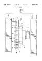
- FIG. 3is an exploded perspective view of the avionic connector interface distribution unit in FIG. 1;
- FIG. 4is an exploded perspective view of the avionic connector interface distribution unit in FIG. 2;
- FIG. 5is a side view of the avionic connector interface distribution unit in FIG. 1 prior to attaching the two-piece enclosure;
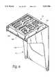
- FIG. 6is a perspective view of the avionic connector interface distribution unit in FIG. 1, showing the unit mounted to an air tray.
- FIGS. 1 and 2illustrate the respective back and front sides of an assembled avionic connector interface distribution unit 10.
- the compact distribution unit 10includes a sheet metal two-piece enclosure 12 for housing the internal components of the unit 10.
- the enclosure 12is formed from a "window frame" cover 12a and a base 12b.
- the cover 12aforms a pair of windows exposing a plurality of miniature pin-type and/or socket-type connectors 14 (FIG. 1), such as subminiature D connectors available from Amp, Inc. of Harrisburg, Pa. These miniature connectors 14 are designed to engage with mating connectors extending from airborne devices.
- the base 12forms an opening exposing a large avionic connector 16 (FIG.
- the avionic connector 16is designed to engage with a mating connector attached to a central controller such as a CTU.
- the components within the enclosure 12include a rigid mother printed wiring board 18, a pair of rigid daughter printed wiring boards 20, 22, and a pair of sheet metal back panels 24, 26.
- the daughter boards 20, 22are generally co-planar and adjacent to each other, and these daughter boards 20, 22 are parallel to the mother board 18.
- the large avionic connector 16is preferably mounted to a first surface 18a of the mother board 18 by means of wave (flow) soldering (FIG. 4).
- a pair of parallel header connectors 28, 30are positioned between a second surface 18b of the mother board 18 and first surfaces of 20a, 22a of the daughter boards 20, 22.
- the headers 28, 30are implemented with HDI (high density) connectors available from Amp, Inc.
- Male (pin) portions 28a, 30a of the respective headers 28, 30are preferably mounted to the second surface 18b of the mother board 18 by means of fountain soldering (FIG. 3).
- the mother board 18is preferably composed of several thin layers containing conductive paths (traces) which electrically connect the terminals of the large connector 16 to the terminals of the male header portions 28a, 30a. These conductive paths are constructed and arranged to minimize signal line crosstalk and control impedance, minimize radiated emissions and susceptability, and minimize voltage gradients/losses.
- Female (socket) portions 28b, 30b of the respective headers 28, 30are preferably mounted to respective first surfaces 20a, 22a of the daughter boards 20, 22 by means of fountain soldering (FIG. 4).
- the plurality of miniature connectors 14are mounted to second surfaces 20b, 22b of the daughter boards 20, 22 by means of wave soldering (FIG. 3).
- the daughter boards 20, 22are preferably composed of several thin layers containing conductive paths (traces) which electrically connect the terminals of the miniature connectors 14 to the terminals of the female header portions 28b, 30b. These conductive paths are constructed and arranged to minimize signal line crosstalk and control impedance, minimize radiated emissions and susceptability, and minimize voltage gradients/losses.
- standoffs 32Prior to mounting the miniature connectors 14 to the daughter boards 20, 22, it is desirable to install standoffs 32 into the daughter boards 20, 22 and then attach the connectors 14 to the standoffs 32 (FIG. 3).
- a pair of standoffs 32are employed with each miniature connector 14.
- the standoffs 32are used to support the shoulders of the miniature connectors 14 at an equal distance from the daughter boards 20, 22, thereby aligning the miniature connectors 14 relative to each other and providing the distribution unit 10 with mechanical integrity.
- the back panels 24, 26are attached to the miniature connectors 14 using screwlocks 34 (FIG. 3).
- the male threaded portions of the screwlocks 34are inserted into corresponding apertures 36 in the back panels 24, 26 and then threaded into threaded axial bores extending through the standoffs 32.
- the small circular apertures 36 in the back panels 24, 26are spaced in accordance with the standoffs 32 such that the apertures 36 are the same in number, arrangement, and spacing as the standoffs 32.
- the back panels 24, 26are provided with relatively large apertures 37 to accommodate the miniature connectors 14. As illustrated in FIG. 1, the miniature connectors 14 protrude through these large apertures 37 when the distribution unit 10 is in assembled form.
- the distribution unit 10includes a cylindrical power connector 15 available from Amp, Inc.
- the power connector 15passes through a large circular aperture in the back panel 24, and a shoulder of the power connector 15 is fastened to the back panel 26 using conventional means such as screws or bolts.
- a corner section of the daughter board 22is cut away to accommodate electrical leads (not shown) extending from the power connector 15. These electrical leads are connected to both the mother board 18 and the daughter boards 20, 22.
- each jackscrew 38In preparation for mating the female header portions 28b, 30b with the respective male header portions 28a, 30a, two jackscrews 38 are installed at opposing ends of each of the female header portions 28b, 30b. Each jackscrew 38 passes through aligned apertures in its associated female header portion, daughter board, and back panel. The male fitting of each jackscrew 38 protrudes from its associated female header portion in the direction of the mating male header portion.
- the female header portions 28b, 30bare first mated with the respective male header portions 28a, 30a.
- the male fittings of the jackscrews 38are threaded into corresponding threaded holes 40 formed in the male header portions 28a, 30a by rotating the heads of the jackscrews 38 (FIG. 3). Since the jackscrews 38 pass through their associated back panels, the heads of the jackscrews 38 are externally accessible from the front side of the distribution unit 10 for purposes of rotating the heads of the jackscrews 38.
- the distribution unit 10appears as depicted in FIG. 5.
- the final assembly stepsinvolve securing the assembled internal components of the distribution unit 10 within the two-piece enclosure 12.
- the "window frame" cover 12ais first attached to the back panels 24, 26 using conventional means such as screws or bolts.
- the cover 12a of the enclosure 12is then attached to the base 12b using screws or bolts.
- the completely assembled distribution unit 10is illustrated in FIGS. 1 and 2.
- connector interface distribution unit 10is that it is considerably more compact than previous structures (i.e., hard-wiring) for connecting central controllers to airborne devices.
- the unit 10is able to accommodate normal dimensional tolerances.
- the use of two daughter boards 20, 22permits each of the headers 28, 30 to move independently, thereby allowing each of the headers 28, 30 to be bottomed-out using the jackscrews 38.
- the jackscrews 38facilitate assembly and disassembly of the unit 10 and ensure that the female and male portions of the headers 28, 30 are fully mated for vibration endurance.
- Second, the use of two daughter boards 20, 22reduces the mating forces between the female and male portions of the headers 28, 30. Stress on one of the headers 28, 30 does not directly cause stress to the other of the headers 28, 30 because the headers 28, 30 are free to move independently.
- the daughter boards 20, 22are not rigidly connected to each other, the daughter boards 20, 22 are free to shift and "float" somewhat relative to each other.
- the headers 28, 30need not be closely registered with respect to each other using special tooling fixtures and extra process controls. For example, if the distance between the female header portions 28b, 30b is not exactly equal to the distance between the male header portions 28a, 30a prior to mating the female header portions 28b, 30b with the respective male header portions 28a, 30a, the daughter boards 20, 22 will shift relative to each other so that the female header portions 28b, 30b properly register and mate with the respective male header portions 28a, 30a.
- the distance between the female header portionswould need to be virtually identical to the distance between the male header portions to permit proper alignment of sockets and pins during mating.
- the allowable manufacturing toleranceswould be severely limited, which in turn would increase the cost of manufacturing.
- a further advantageous feature of the connector interface distribution unit 10is that the unit 10 is designed to perform adequately under vibration.
- the jackscrews 38ensure that the female and male portions of the headers 28, 30 are fully mated so as to promote positive performance of the unit 10 under vibration.
- the standoffs 32support the miniature connectors 14 at an equal distance from the surfaces 20b, 22b of the daughter boards 20, 22 and since the back panels 24, 26 are fastened to the standoffs 32, the standoffs 32 effectively fortify the daughter boards 20, 22.
- the connector interface distribution unit 10facilitates servicing thereof.
- the distribution unit 10is mounted to an air tray 11 of an aircraft.
- the enclosure 12 of the unit 10is attached to the air tray 11 with the cover 12a facing a back side 11a of the air tray 11 and the base 12b facing a front side 11b of the air tray 11.
- the air tray 11is typically mounted in the aircraft such that the front side 11b of the air tray 11 is more accessible to service personnel than the back side 11a. If the servicing merely entails connection or disconnection of one or more connectors which mate with the miniature connectors 14, the service personnel can easily access the unit 10 via the front side 11b of the air tray 11, detach the unit 10 from the air tray 11, and quickly connect or disconnect the appropriate connectors.
- the servicingentails repairing a problem which has developed in the unit 10
- the service personnelcan easily detach the unit 10 from the air tray 11 and replace the unit 10 with one which works properly.
- the unit requiring repaircan then be brought to a maintenance facility away from the aircraft.
- the distribution unit 10may employ more or less than two headers, two daughter boards, and two back panels, depending upon the number of required interconnections between the large avionic connector 16 and the miniature connectors 14.
- the number of miniature connectors 14would be reduced and, accordingly, only one header, one daughter board, and one back panel might be required to accommodate the reduced number of interconnections.
- the number of miniature connectors 14would be increased and, accordingly, more than two headers, daughter boards, and back panels might be required. It is preferable to mount the headers on separate daughter boards so that the distribution unit is able to accommodate normal dimensional tolerances.
Landscapes
- Engineering & Computer Science (AREA)
- Microelectronics & Electronic Packaging (AREA)
- Mechanical Engineering (AREA)
- Coupling Device And Connection With Printed Circuit (AREA)
- Connector Housings Or Holding Contact Members (AREA)
Abstract
Description
Claims (15)
Priority Applications (8)
| Application Number | Priority Date | Filing Date | Title |
|---|---|---|---|
| US08/337,290US5622506A (en) | 1994-11-10 | 1994-11-10 | Avionic connector interface distribution unit |
| DE69517997TDE69517997T2 (en) | 1994-11-10 | 1995-10-24 | AVIATION TECHNICAL INTERFACE DISTRIBUTION UNIT |
| CA002204859ACA2204859C (en) | 1994-11-10 | 1995-10-24 | Avionic connector interface distribution unit |
| AU41318/96AAU4131896A (en) | 1994-11-10 | 1995-10-24 | Avionic connector interface distribution unit |
| EP95939537AEP0791234B1 (en) | 1994-11-10 | 1995-10-24 | Avionic connector interface distribution unit |
| PCT/US1995/013397WO1996015566A1 (en) | 1994-11-10 | 1995-10-24 | Avionic connector interface distribution unit |
| CN95196184ACN1069449C (en) | 1994-11-10 | 1995-10-24 | Avionic connector interface distribution unit |
| MXPA/A/1997/003428AMXPA97003428A (en) | 1994-11-10 | 1997-05-09 | Interface distribution unit paraconectador de electronica aeronaut |
Applications Claiming Priority (1)
| Application Number | Priority Date | Filing Date | Title |
|---|---|---|---|
| US08/337,290US5622506A (en) | 1994-11-10 | 1994-11-10 | Avionic connector interface distribution unit |
Publications (1)
| Publication Number | Publication Date |
|---|---|
| US5622506Atrue US5622506A (en) | 1997-04-22 |
Family
ID=23319911
Family Applications (1)
| Application Number | Title | Priority Date | Filing Date |
|---|---|---|---|
| US08/337,290Expired - LifetimeUS5622506A (en) | 1994-11-10 | 1994-11-10 | Avionic connector interface distribution unit |
Country Status (6)
| Country | Link |
|---|---|
| US (1) | US5622506A (en) |
| EP (1) | EP0791234B1 (en) |
| CN (1) | CN1069449C (en) |
| AU (1) | AU4131896A (en) |
| DE (1) | DE69517997T2 (en) |
| WO (1) | WO1996015566A1 (en) |
Cited By (22)
| Publication number | Priority date | Publication date | Assignee | Title |
|---|---|---|---|---|
| US6053778A (en)* | 1998-01-26 | 2000-04-25 | Lucent Technologies, Inc. | Rigidizing cover plate for a printed wiring board mounted terminal block |
| USD425483S (en) | 1998-06-30 | 2000-05-23 | Honeywell Inc. | Interconnection device |
| US6089902A (en)* | 1998-12-01 | 2000-07-18 | Lucent Technologies, Inc. | Miniature connector assembly, a miniature connector retrofit kit and a method for making and using the same |
| US6146153A (en)* | 1999-03-09 | 2000-11-14 | 3Com Corporation | Adapter apparatus and method for transmitting electronic data |
| USD439883S1 (en) | 1999-05-28 | 2001-04-03 | Smc Corporation | Electric connector assembly |
| USD439882S1 (en) | 1999-05-28 | 2001-04-03 | Smc Corporation | Electric connector assembly |
| USD448344S1 (en) | 1999-10-01 | 2001-09-25 | Smc Kabushiki Kaisha | Signal converter |
| US6364670B1 (en) | 1998-11-18 | 2002-04-02 | Robert Bosch Corporation | Junction box having function electronics |
| US20030157818A1 (en)* | 2002-02-19 | 2003-08-21 | Meersschaut Bernard Van Den | Connection block suitable for being inserted in a cavity of a metal box of a multicontact connector |
| US20060172601A1 (en)* | 2005-02-03 | 2006-08-03 | Neil Faulkner | Module for the assembly of two sets of connections |
| US7335056B1 (en)* | 2006-10-19 | 2008-02-26 | Adc Telecommunications, Inc. | RJ to RJ swing panel |
| US20100146184A1 (en)* | 2002-09-11 | 2010-06-10 | Stephen Redford | Cabin telecommunication unit |
| US20130075530A1 (en)* | 2011-09-27 | 2013-03-28 | Mark Stephen Shander | Methods and systems for incorporating translating backplanes to facilitate wire separation |
| US8918985B1 (en)* | 2011-05-10 | 2014-12-30 | Bae Systems Information And Electronic Systems Integration Inc. | Modular mounting and input/output |
| US20170245367A1 (en)* | 2016-02-22 | 2017-08-24 | Raytheon Company | Circuit card assembly (cca) with reduced susceptibility to deform under loading |
| US10069226B2 (en)* | 2017-01-31 | 2018-09-04 | Murrelektronik, Inc. | Power distribution module |
| US11056810B2 (en)* | 2019-05-17 | 2021-07-06 | Marelli Automotive Lighting Reutlingen (Germany) GmbH | Circuit board with a plug connection |
| WO2022087440A1 (en)* | 2020-10-22 | 2022-04-28 | Peterson Manufacturing Company | Power routing module with ports |
| USD981346S1 (en)* | 2021-11-19 | 2023-03-21 | Beckhoff Automation Gmbh | Electric power distribution device |
| FR3130498A1 (en)* | 2021-12-09 | 2023-06-16 | Latelec | Electric cabinet multi-URL chair. |
| USD1022910S1 (en)* | 2021-11-19 | 2024-04-16 | Beckhoff Automation Gmbh | Baseplate of a modular equipment for distribution of electric power and data signals |
| USD1023961S1 (en)* | 2021-11-19 | 2024-04-23 | Beckhoff Automation Gmbh | Baseplate of a modular equipment for distribution of electric power and data signals |
Families Citing this family (4)
| Publication number | Priority date | Publication date | Assignee | Title |
|---|---|---|---|---|
| CN1075904C (en)* | 1996-05-21 | 2001-12-05 | 华为技术有限公司 | Insertion board conencting method and tructure thereof |
| JP4114497B2 (en) | 2003-02-14 | 2008-07-09 | 住友電装株式会社 | CASE FOR CIRCUIT COMPOSITE AND METHOD FOR MANUFACTURING CIRCUIT COMPOSITION |
| FR2982433B1 (en)* | 2011-11-07 | 2015-02-27 | Aton Systemes | DEVICE FOR CONNECTING ELECTRONIC EQUIPMENT, CONTROL PLANT AND CORRESPONDING VEHICLE |
| US9550752B2 (en)* | 2013-04-12 | 2017-01-24 | Bayer Cropscience Aktiengesellschaft | Triazolinthione derivatives |
Citations (5)
| Publication number | Priority date | Publication date | Assignee | Title |
|---|---|---|---|---|
| US4824398A (en)* | 1987-08-21 | 1989-04-25 | Amp Incorporated | Solderable standoff boardlock |
| US4944684A (en)* | 1988-06-28 | 1990-07-31 | Trw, Inc. | Electrical junction box and method for its manufacture |
| US5169335A (en)* | 1991-02-13 | 1992-12-08 | James L. Sayre | Thru-board released connector |
| US5227955A (en)* | 1990-10-29 | 1993-07-13 | Souriau Et Cie | Distribution box and method of manufacturing such a box |
| US5353190A (en)* | 1992-06-09 | 1994-10-04 | Yazaki Corporation | Electric junction box |
Family Cites Families (6)
| Publication number | Priority date | Publication date | Assignee | Title |
|---|---|---|---|---|
| DE3334097C1 (en)* | 1983-09-21 | 1985-04-04 | Bayerische Motoren Werke AG, 8000 München | Central power distributor for the wiring of motor vehicles |
| US4689718A (en)* | 1986-04-04 | 1987-08-25 | United Technologies Automotive, Inc. | Programmable junction box |
| US4781600A (en)* | 1986-06-25 | 1988-11-01 | Yazaki Corporation | Junction box and a process of assembling the same |
| US4834398A (en)* | 1987-08-31 | 1989-05-30 | S & B Technical Products, Inc. | Pipe gasket |
| JPH0613558Y2 (en)* | 1988-02-10 | 1994-04-06 | 矢崎総業株式会社 | Automotive wiring device |
| US4993965A (en)* | 1988-05-10 | 1991-02-19 | E. I. Du Pont De Nemours And Company | Support for floated header/connector |
- 1994
- 1994-11-10USUS08/337,290patent/US5622506A/ennot_activeExpired - Lifetime
- 1995
- 1995-10-24CNCN95196184Apatent/CN1069449C/ennot_activeExpired - Fee Related
- 1995-10-24WOPCT/US1995/013397patent/WO1996015566A1/enactiveIP Right Grant
- 1995-10-24AUAU41318/96Apatent/AU4131896A/ennot_activeAbandoned
- 1995-10-24DEDE69517997Tpatent/DE69517997T2/ennot_activeExpired - Lifetime
- 1995-10-24EPEP95939537Apatent/EP0791234B1/ennot_activeExpired - Lifetime
Patent Citations (5)
| Publication number | Priority date | Publication date | Assignee | Title |
|---|---|---|---|---|
| US4824398A (en)* | 1987-08-21 | 1989-04-25 | Amp Incorporated | Solderable standoff boardlock |
| US4944684A (en)* | 1988-06-28 | 1990-07-31 | Trw, Inc. | Electrical junction box and method for its manufacture |
| US5227955A (en)* | 1990-10-29 | 1993-07-13 | Souriau Et Cie | Distribution box and method of manufacturing such a box |
| US5169335A (en)* | 1991-02-13 | 1992-12-08 | James L. Sayre | Thru-board released connector |
| US5353190A (en)* | 1992-06-09 | 1994-10-04 | Yazaki Corporation | Electric junction box |
Cited By (30)
| Publication number | Priority date | Publication date | Assignee | Title |
|---|---|---|---|---|
| US6053778A (en)* | 1998-01-26 | 2000-04-25 | Lucent Technologies, Inc. | Rigidizing cover plate for a printed wiring board mounted terminal block |
| USD425483S (en) | 1998-06-30 | 2000-05-23 | Honeywell Inc. | Interconnection device |
| US6364670B1 (en) | 1998-11-18 | 2002-04-02 | Robert Bosch Corporation | Junction box having function electronics |
| US6089902A (en)* | 1998-12-01 | 2000-07-18 | Lucent Technologies, Inc. | Miniature connector assembly, a miniature connector retrofit kit and a method for making and using the same |
| US6146153A (en)* | 1999-03-09 | 2000-11-14 | 3Com Corporation | Adapter apparatus and method for transmitting electronic data |
| USD439883S1 (en) | 1999-05-28 | 2001-04-03 | Smc Corporation | Electric connector assembly |
| USD439882S1 (en) | 1999-05-28 | 2001-04-03 | Smc Corporation | Electric connector assembly |
| USD448344S1 (en) | 1999-10-01 | 2001-09-25 | Smc Kabushiki Kaisha | Signal converter |
| US20030157818A1 (en)* | 2002-02-19 | 2003-08-21 | Meersschaut Bernard Van Den | Connection block suitable for being inserted in a cavity of a metal box of a multicontact connector |
| US6857882B2 (en)* | 2002-02-19 | 2005-02-22 | Radiall | Connection block suitable for being inserted in a cavity of a metal box of a multicontact connector |
| US8140732B2 (en)* | 2002-09-11 | 2012-03-20 | Gte Wireless Incorporated | Cabin telecommunication unit |
| US20100146184A1 (en)* | 2002-09-11 | 2010-06-10 | Stephen Redford | Cabin telecommunication unit |
| US20060172601A1 (en)* | 2005-02-03 | 2006-08-03 | Neil Faulkner | Module for the assembly of two sets of connections |
| US7168989B2 (en)* | 2005-02-03 | 2007-01-30 | Souriau | Module for the assembly of two sets of connections |
| US7335056B1 (en)* | 2006-10-19 | 2008-02-26 | Adc Telecommunications, Inc. | RJ to RJ swing panel |
| US8918985B1 (en)* | 2011-05-10 | 2014-12-30 | Bae Systems Information And Electronic Systems Integration Inc. | Modular mounting and input/output |
| RU2625915C2 (en)* | 2011-09-27 | 2017-07-19 | Зе Боинг Компани | Method and system of building in integrating extension boards to facilitate wire separation |
| JP2013071731A (en)* | 2011-09-27 | 2013-04-22 | Boeing Co:The | Method and system for incorporating translating backplane to facilitate wire separation |
| US8936217B2 (en)* | 2011-09-27 | 2015-01-20 | The Boeing Company | Methods and systems for incorporating translating backplanes to facilitate wire separation |
| US20130075530A1 (en)* | 2011-09-27 | 2013-03-28 | Mark Stephen Shander | Methods and systems for incorporating translating backplanes to facilitate wire separation |
| US20170245367A1 (en)* | 2016-02-22 | 2017-08-24 | Raytheon Company | Circuit card assembly (cca) with reduced susceptibility to deform under loading |
| US10069226B2 (en)* | 2017-01-31 | 2018-09-04 | Murrelektronik, Inc. | Power distribution module |
| US11056810B2 (en)* | 2019-05-17 | 2021-07-06 | Marelli Automotive Lighting Reutlingen (Germany) GmbH | Circuit board with a plug connection |
| WO2022087440A1 (en)* | 2020-10-22 | 2022-04-28 | Peterson Manufacturing Company | Power routing module with ports |
| US11889639B2 (en) | 2020-10-22 | 2024-01-30 | Peterson Manufacturing Company | Power routing module with ports |
| US12302509B2 (en) | 2020-10-22 | 2025-05-13 | Peterson Manufacturing Company | Power routing module with ports |
| USD981346S1 (en)* | 2021-11-19 | 2023-03-21 | Beckhoff Automation Gmbh | Electric power distribution device |
| USD1022910S1 (en)* | 2021-11-19 | 2024-04-16 | Beckhoff Automation Gmbh | Baseplate of a modular equipment for distribution of electric power and data signals |
| USD1023961S1 (en)* | 2021-11-19 | 2024-04-23 | Beckhoff Automation Gmbh | Baseplate of a modular equipment for distribution of electric power and data signals |
| FR3130498A1 (en)* | 2021-12-09 | 2023-06-16 | Latelec | Electric cabinet multi-URL chair. |
Also Published As
| Publication number | Publication date |
|---|---|
| EP0791234B1 (en) | 2000-07-12 |
| EP0791234A4 (en) | 1998-02-04 |
| EP0791234A1 (en) | 1997-08-27 |
| AU4131896A (en) | 1996-06-06 |
| WO1996015566A1 (en) | 1996-05-23 |
| CN1069449C (en) | 2001-08-08 |
| CN1164299A (en) | 1997-11-05 |
| MX9703428A (en) | 1998-07-31 |
| DE69517997T2 (en) | 2000-12-07 |
| DE69517997D1 (en) | 2000-08-17 |
Similar Documents
| Publication | Publication Date | Title |
|---|---|---|
| US5622506A (en) | Avionic connector interface distribution unit | |
| US6535397B2 (en) | Interconnect structure for interconnecting electronic modules | |
| US20080076292A1 (en) | Connectors To Connect Modules To Electronic Devices | |
| US6320750B2 (en) | Sub-modular configurable avionics | |
| US4632476A (en) | Terminal grounding unit | |
| US5906512A (en) | Electronics box coaxial connection assembly | |
| US6545850B1 (en) | Backplane power landing system | |
| US20240334632A1 (en) | Expansion Card, Mainboard, Server, and Expansion Card Manufacturing Method | |
| US20070111596A1 (en) | Multi-port rf connector | |
| US20020090844A1 (en) | Segmented replaceable backplane system for electronic apparatus | |
| US5234348A (en) | Front removable/serviceable RF backplane | |
| CN111052883B (en) | Module mounting adapter plate | |
| US6729913B2 (en) | Network branch connector and method and system incorporating same | |
| CN113022888A (en) | Satellite structure and satellite assembly method | |
| US6350130B1 (en) | Electrically coupling an avionics line replaceable unit with an avionics test station | |
| CA2204859C (en) | Avionic connector interface distribution unit | |
| US7128616B1 (en) | High speed data transmission cable connector system | |
| US5408240A (en) | Suspended stripline RF feed with orthogonal coaxial transitions and plastic housing | |
| US7267568B2 (en) | Floating connectors | |
| US20030036313A1 (en) | Plug connector with adapter | |
| US7163405B2 (en) | Connector assembly apparatus for electronic equipment and method for using same | |
| CN114828604B (en) | A radio frequency receiving component with a modular electromagnetic signal shielding shell | |
| MXPA97003428A (en) | Interface distribution unit paraconectador de electronica aeronaut | |
| KR102716225B1 (en) | Compatible connector for a vehicle | |
| CN114389065B (en) | PXI radio frequency module and radio frequency microwave system |
Legal Events
| Date | Code | Title | Description |
|---|---|---|---|
| AS | Assignment | Owner name:GTE AIRFONE INCORPORATTED, ILLINOIS Free format text:ASSIGNMENT OF ASSIGNORS INTEREST;ASSIGNORS:HORNIG, JAMES F.;LYON, RICHARD A.;SHEFFIELD, JAMES W.;AND OTHERS;REEL/FRAME:007466/0356;SIGNING DATES FROM 19941117 TO 19941201 | |
| STCF | Information on status: patent grant | Free format text:PATENTED CASE | |
| FEPP | Fee payment procedure | Free format text:PAYOR NUMBER ASSIGNED (ORIGINAL EVENT CODE: ASPN); ENTITY STATUS OF PATENT OWNER: LARGE ENTITY | |
| FPAY | Fee payment | Year of fee payment:4 | |
| FPAY | Fee payment | Year of fee payment:8 | |
| SULP | Surcharge for late payment | Year of fee payment:7 | |
| FPAY | Fee payment | Year of fee payment:12 | |
| AS | Assignment | Owner name:GTE WIRELESS INCORPORATED, NEW JERSEY Free format text:ASSIGNMENT OF ASSIGNORS INTEREST;ASSIGNOR:AIRFONE INC.;REEL/FRAME:024741/0517 Effective date:20081231 Owner name:AIRFONE INC., ILLINOIS Free format text:CHANGE OF NAME;ASSIGNOR:VERIZON AIRFONE INC.;REEL/FRAME:024741/0585 Effective date:20081231 Owner name:VERIZON AIRFONE INC., ILLINOIS Free format text:CHANGE OF NAME;ASSIGNOR:GTE AIRFONE INCORPORATED;REEL/FRAME:024741/0600 Effective date:20011204 | |
| AS | Assignment | Owner name:VERIZON PATENT AND LICENSING INC., NEW JERSEY Free format text:ASSIGNMENT OF ASSIGNORS INTEREST;ASSIGNOR:GTE WIRELESS INCORPORATED;REEL/FRAME:029310/0172 Effective date:20121107 |